EP3527974A1 - Inspection devices and methods of inspecting a slot - Google Patents
Inspection devices and methods of inspecting a slot Download PDFInfo
- Publication number
- EP3527974A1 EP3527974A1 EP19152940.3A EP19152940A EP3527974A1 EP 3527974 A1 EP3527974 A1 EP 3527974A1 EP 19152940 A EP19152940 A EP 19152940A EP 3527974 A1 EP3527974 A1 EP 3527974A1
- Authority
- EP
- European Patent Office
- Prior art keywords
- slot
- insert
- inspection device
- imaging devices
- inspecting
- Prior art date
- Legal status (The legal status is an assumption and is not a legal conclusion. Google has not performed a legal analysis and makes no representation as to the accuracy of the status listed.)
- Granted
Links
Images



Classifications
-
- G—PHYSICS
- G01—MEASURING; TESTING
- G01N—INVESTIGATING OR ANALYSING MATERIALS BY DETERMINING THEIR CHEMICAL OR PHYSICAL PROPERTIES
- G01N21/00—Investigating or analysing materials by the use of optical means, i.e. using sub-millimetre waves, infrared, visible or ultraviolet light
- G01N21/84—Systems specially adapted for particular applications
- G01N21/88—Investigating the presence of flaws or contamination
- G01N21/8851—Scan or image signal processing specially adapted therefor, e.g. for scan signal adjustment, for detecting different kinds of defects, for compensating for structures, markings, edges
-
- G—PHYSICS
- G01—MEASURING; TESTING
- G01N—INVESTIGATING OR ANALYSING MATERIALS BY DETERMINING THEIR CHEMICAL OR PHYSICAL PROPERTIES
- G01N21/00—Investigating or analysing materials by the use of optical means, i.e. using sub-millimetre waves, infrared, visible or ultraviolet light
- G01N21/84—Systems specially adapted for particular applications
- G01N21/88—Investigating the presence of flaws or contamination
- G01N21/95—Investigating the presence of flaws or contamination characterised by the material or shape of the object to be examined
- G01N21/954—Inspecting the inner surface of hollow bodies, e.g. bores
-
- G—PHYSICS
- G02—OPTICS
- G02B—OPTICAL ELEMENTS, SYSTEMS OR APPARATUS
- G02B23/00—Telescopes, e.g. binoculars; Periscopes; Instruments for viewing the inside of hollow bodies; Viewfinders; Optical aiming or sighting devices
- G02B23/24—Instruments or systems for viewing the inside of hollow bodies, e.g. fibrescopes
- G02B23/2476—Non-optical details, e.g. housings, mountings, supports
- G02B23/2484—Arrangements in relation to a camera or imaging device
-
- F—MECHANICAL ENGINEERING; LIGHTING; HEATING; WEAPONS; BLASTING
- F01—MACHINES OR ENGINES IN GENERAL; ENGINE PLANTS IN GENERAL; STEAM ENGINES
- F01D—NON-POSITIVE DISPLACEMENT MACHINES OR ENGINES, e.g. STEAM TURBINES
- F01D21/00—Shutting-down of machines or engines, e.g. in emergency; Regulating, controlling, or safety means not otherwise provided for
- F01D21/003—Arrangements for testing or measuring
-
- G—PHYSICS
- G01—MEASURING; TESTING
- G01N—INVESTIGATING OR ANALYSING MATERIALS BY DETERMINING THEIR CHEMICAL OR PHYSICAL PROPERTIES
- G01N21/00—Investigating or analysing materials by the use of optical means, i.e. using sub-millimetre waves, infrared, visible or ultraviolet light
- G01N21/84—Systems specially adapted for particular applications
- G01N21/88—Investigating the presence of flaws or contamination
- G01N21/8806—Specially adapted optical and illumination features
-
- G—PHYSICS
- G01—MEASURING; TESTING
- G01N—INVESTIGATING OR ANALYSING MATERIALS BY DETERMINING THEIR CHEMICAL OR PHYSICAL PROPERTIES
- G01N21/00—Investigating or analysing materials by the use of optical means, i.e. using sub-millimetre waves, infrared, visible or ultraviolet light
- G01N21/84—Systems specially adapted for particular applications
- G01N21/88—Investigating the presence of flaws or contamination
- G01N21/95—Investigating the presence of flaws or contamination characterised by the material or shape of the object to be examined
- G01N21/956—Inspecting patterns on the surface of objects
- G01N21/95692—Patterns showing hole parts, e.g. honeycomb filtering structures
-
- G—PHYSICS
- G06—COMPUTING OR CALCULATING; COUNTING
- G06T—IMAGE DATA PROCESSING OR GENERATION, IN GENERAL
- G06T7/00—Image analysis
- G06T7/0002—Inspection of images, e.g. flaw detection
- G06T7/0004—Industrial image inspection
-
- G—PHYSICS
- G01—MEASURING; TESTING
- G01N—INVESTIGATING OR ANALYSING MATERIALS BY DETERMINING THEIR CHEMICAL OR PHYSICAL PROPERTIES
- G01N21/00—Investigating or analysing materials by the use of optical means, i.e. using sub-millimetre waves, infrared, visible or ultraviolet light
- G01N21/84—Systems specially adapted for particular applications
- G01N21/88—Investigating the presence of flaws or contamination
- G01N21/95—Investigating the presence of flaws or contamination characterised by the material or shape of the object to be examined
- G01N21/954—Inspecting the inner surface of hollow bodies, e.g. bores
- G01N2021/9542—Inspecting the inner surface of hollow bodies, e.g. bores using a probe
- G01N2021/9546—Inspecting the inner surface of hollow bodies, e.g. bores using a probe with remote light transmitting, e.g. optical fibres
-
- G—PHYSICS
- G06—COMPUTING OR CALCULATING; COUNTING
- G06T—IMAGE DATA PROCESSING OR GENERATION, IN GENERAL
- G06T2207/00—Indexing scheme for image analysis or image enhancement
- G06T2207/30—Subject of image; Context of image processing
- G06T2207/30108—Industrial image inspection
- G06T2207/30164—Workpiece; Machine component
Definitions
- the disclosure relates to inspection devices and methods of inspecting a slot.
- an inspection device for inspecting a slot of a gas turbine engine.
- the inspection device comprises: an insert for insertion into the slot; a plurality of imaging devices coupled to the insert; and a processor.
- the insert is movable along a longitudinal axis of the slot.
- Each of the plurality of imaging devices is positioned adjacent an external surface of the insert and is configured to capture an image of a portion of the slot adjacent the imaging device.
- the processor is configured to receive data corresponding to the images captured by the plurality of imaging devices.
- the insert may have an external profile, a portion of which corresponds to an internal profile of the slot.
- the slot may be a fir-tree slot.
- the plurality of imaging devices may be arranged at multiple heights along the insert.
- Each of the imaging devices may have a field of view.
- the total field of view of the imaging devices may span substantially an entire height of the slot.
- the inspection device may further comprise a plurality of illumination devices coupled to the insert.
- the plurality of illumination devices may be positioned adjacent an external surface of the insert.
- Each of the plurality of illumination devices may be configured to illuminate a portion of the slot adjacent the illumination device.
- the insert may be substantially transparent and acts as a light guide.
- Each of the imaging devices may comprise a bundle of optical fibres.
- Each of the imaging devices may comprise a camera disposed adjacent the external surface of the insert.
- the processor may be configured to generate a single image from the data.
- the inspection device may further comprise a display configured to display images based on the data.
- a method of inspecting a slot using the inspection device of any preceding statement comprises: inserting the insert into the slot at a first position; capturing an image using each of the imaging devices with the insert at the first position; moving the insert to one or more further positions; and capturing an image using each of the imaging devices with the insert at the one or more further positions.
- the method may further comprise illuminating the slot using one or more illumination devices.
- Images of the entire length and height of at least one side of the slot may be captured.
- a single image of the entire length and height of the slot may be generated based on the images.
- the base 14 has a square cross-sectional profile.
- the first arm 16a and the second arm 16b extend from opposing sides of the base 14.
- the first wheel 18a is attached to an end of the first arm 16a and the second wheel 18b is attached to an end of the second arm 16b.
- the slot 6 has a first side 17 and a second side 19.
- the first side 17 is a pressure side of the slot 6.
- the first wheel 18a and the second wheel 18b engage with an upper surface 24 of the component 4 on opposing sides of the slot 6, adjacent the first and second sides 17, 19.
- the first and second wheels 18a, 18b are configured to rotate about an axis of rotation 26 extending perpendicularly to a longitudinal axis 22 of the slot 6.
- the guide 12 extends from a lower surface of the base 14 such that the guide 12 is supported within the slot 6.
- the guide 12 is formed by a contoured plate 28.
- the plate 28 comprises a first side portion 30 and a second side portion 32.
- the first side portion 30 faces the first side 17 of the slot 6 and the second side portion 32 faces the second side 19 of the slot 6.
- the guide 12 is bounded at one of its ends by an end plate 34 and is open at its other end.
- An outer surface of the guide 12 has a cross-sectional profile substantially corresponding to and inwardly offset from the cross-sectional profile of the inner surface of the slot 6.
- the component 4 is a disc of a gas turbine engine and the slot 6 forms part of a fir-tree joint.
- the inner surface of the slot 6 has a fir-tree-shaped cross-section and the outer surface of the guide 12 has a fir-tree-shaped cross-section corresponding to but slightly smaller than the fir-tree-shaped cross-section of the inner surface of the slot 6. Accordingly, a gap 20 is formed between the inner surface of the slot 6 and the outer surface of the guide 12.
- the guide 12 is therefore able to move along the slot 6 along the longitudinal axis 22 of the slot 22 upon rotation of the first and second wheels 18a, 18b about the axis of rotation 26.
- the guide 12 has a constant cross-section along its length, with the length dimension being represented by the letter I in Figure 1 .
- a first plurality of holes and a second plurality of holes extend through the first side portion 30 of the plate 28 between a hollow interior 34 of the guide 12 and an exterior of the guide 12.
- the first plurality of holes are arranged along the height of the guide 12 between a lower end of the guide 12 and an upper end of the guide 12, with the height dimension being represented by the letter h in Figure 1 .
- the second plurality of holes are also arranged along the height of the guide 12.
- a first optical fibre housing 36 (shown in grey in Figure 1 ) is attached to each of the first plurality of holes.
- a bundle of first optical fibres 40a, 40b (not shown in Figure 1 ) configured for conveying image data is supported by each first optical fibre housing 36 and extends through each of the first plurality of holes.
- a second optical fibre housing 38 (shown in white in Figure 1 ) is attached to each of the second plurality of holes.
- a bundle of second optical fibres 42 (not shown in Figure 1 ) suitable for conveying light is supported by each second optical fibre housing 38 and extends through each of the second plurality of holes.
- the ends of the bundle of first optical fibres 40a, 40b and the bundles of second optical fibres 42 terminate at the outer surface of the guide 12.
- the bundles of first optical fibres 40a, 40b and the bundles of second optical fibres 42 are optically connected to the imaging system 10.
- FIG. 2 is a schematic view of the imaging system 10 of the inspection device 2.
- the imaging system 10 generally comprises an imaging segment 44 and an illumination segment 46.
- the imaging segment 44 comprises the plurality of bundles of first optical fibres 40a, 40b referred to previously.
- the imaging segment 44 additionally comprises an objective lens 48, a CCD camera 50, a computer 52 and a monitor 54. Only two bundles of first optical fibres 40a, 40b are shown in Figure 2 , for clarity.
- the objective lens 48 is optically connected to one of the plurality of bundles of first optical fibres 40a, 40b. In Figure 2 , the objective lens 48 is optically connected to the bundle of first optical fibres 40a.
- the CCD camera 50 is positioned adjacent the objective lens 48 so as to record optical images received therefrom.
- the objective lens 48 and the CCD camera 50 are movable between each of the plurality of bundles of first optical fibres 40a, 40b (as indicated in dashed lines in Figure 2 ).
- the CCD camera 50 is connected to the computer 52, which is in turn connected to the monitor 54.
- the illumination segment 46 comprises the plurality of bundles of second optical fibres 42 referred to previously.
- the illumination segment 46 additionally comprises a beam splitter 56, a single mode fibre 58, an objective lens 60 and a laser source 62. Only two bundles of second optical fibres 42 are shown in Figure 2 , for clarity. Each of the plurality of bundles of second optical fibres 42 are optically connected to the beam splitter 56.
- the beam splitter 56 is optically connected to the objective lens 60 by the single mode fibre 58.
- Figure 3 shows a flow diagram of an inspection method performed using the inspection device 2, and additionally with reference to Figures 1 and 2 .
- step S2 the insert 8 is positioned within the slot 6 at a starting position as shown in Figure 1 .
- the ends of the bundles of first optical fibres 40a, 40b are positioned adjacent an end of the first side 17 of the slot 6.
- the laser source 62 generates a laser beam that passes into the objective lens 60, along the single mode fibre 58 and into the beam splitter 56.
- the beam splitter 56 splits the laser beam into multiple laser beams, each of which pass into a separate one of the plurality of bundles of second optical fibres 42.
- the laser beams pass along the plurality of bundles of second optical fibres 42, through the second plurality of holes extending through the first side portion 30 of the plate 28, and out of the ends of the plurality of bundles of second optical fibres 42, thereby illuminating a portion of the slot 6 adjacent the ends of the plurality of bundles of second optical fibres 42.
- Light from the illuminated slot 6 passes into the plurality of bundles of first optical fibres 40a, 40b, through the first plurality of holes extending through the first side portion 30 of the plate 28 and along the plurality of bundles of first optical fibres 40a, 40b.
- the light from the bundle of first optical fibres 40a passes into the objective lens 48.
- the objective lenses 48 produces an image of the inner surface of the slot 6 adjacent the end of the bundle of first optical fibres 40a.
- the arrangement and proximity of each of the first plurality of holes ensures that fields of view of each of the plurality of bundles of first optical fibres 40a, 40b overlap in a height dimension.
- the CCD camera 50 captures the image generated by objective lens 48 and sends the resulting image data to the computer 52.
- the objective lens 48 and CCD camera 50 then move to a next bundle of first optical fibres (i.e. in the arrangement shown in Figure 2 , the bundle of first optical fibres 40b).
- the CCD camera 50 then captures another image generated by the objective lens 48 in this next position (i.e. an image of the inner surface of the slot 6 adjacent the end of the bundle of first optical fibres 40b) and sends the resulting image data to the computer 52. This process is repeated with the objective lens 48 and CCD camera 50 positioned at all of the bundles of first optical fibres 40a, 40b until image data has been captured for all of the bundles of first optical fibres 40a, 40b.
- image data is captured for a first portion of the surface of the first side 17 of the slot 6 spanning an entire height of the slot 6. Since the profile of the insert 8 substantially corresponds to the profile of the slot 6, the insert 8 is unable to move in the width or height direction, and, thus, the ends of the bundle of first optical fibres 40a, 40b are positioned a fixed distance from the interior wall of the slot 6. This fixed distance allows the camera to focus.
- step S6 the insert 8 is then actuated to a second position adjacent the starting position.
- the guide 12 is actuated along the longitudinal axis 22 of the slot 6.
- step S4 is repeated such that image data is captured for a second portion of the surface of the first side 17 of the slot 6 adjacent the first portion and spanning an entire height of the slot 6.
- the distance by which the insert 8 is actuated during step S6 is small enough that the combined field of view of the plurality of the bundles of first optical fibres 40a, 40b when the insert 8 is in the second position overlaps the combined field of view of the bundles of first optical fibres 40a, 40b when the insert 8 is in the first position in a length direction.
- Steps S6 to S8 are repeated multiple times so as to capture image data at multiple positions (i.e. n positions) along the length of the slot 6 until image data across the entirety of the length of the first side 17 of the slot 6 is captured.
- step S10 the image data captured as a result of steps S2 to S8 is processed into a format suitable for analysis by a user.
- the images are combined into a single image using image stitching.
- the single image is displayed on the monitor 54.
- a user views the image displayed on the monitor 54.
- the user visually inspects the image displayed on the monitor 54.
- the user is able to detect any surface defects present in the first side 17 of the slot by looking at the image displayed on the monitor 54, such as corrosion, cracks or pits.
- the slot 6 and the guide 12 are symmetrical. Accordingly, the guide 12 can be removed from the slot 6, reversed in direction and reinserted into the slot 6 such that the first side portion 30 faces the second side 19 of the slot 6 and the second side portion 32 faces the first side 17 of the slot 6. Steps S2 to S12 can then be repeated so as to allow the user to analyse the second side 19 of the slot.
- FIG 4 shows an alternative inspection device 102 for inspecting the component 4.
- the inspection device 102 generally comprises an insert 104, a jig 106, a linear variable differential transformer (LVDT) 108 and an imaging system 10' substantially corresponding to the imaging system 10 described with reference to Figures 1 to 3 .
- LVDT linear variable differential transformer
- the same dimensional references i.e. length I, width w and height h are used to describe the inspection device 102.
- FIG. 5 shows the insert 104 in isolation.
- the insert 104 comprises a support part 110 and an inspection part 112.
- the support and inspection parts 110, 112 are transparent.
- the support and inspection parts 110, 112 may be 3D printed, for example.
- the support part 110 comprises a rearward portion 114, a middle portion 116 and a forward portion 118.
- the inspection part 112 also comprises a rearward portion 120, a middle portion 122 and a forward portion 124.
- the rearward and forward portion 114, 118 of the support part 110 are narrower than the middle portion 116.
- the rearward and forward portion 120, 124 of the inspection part 112 are wider than the middle portion 122. Accordingly, the support and inspection parts 110, 112 each have a generally T-shaped profile when viewed from above.
- the support part 110 has a first surface 125 (not shown in Figure 5 ) that abuts a first surface 127 (not shown in Figure 5 ) of the inspection part 112.
- the support part 110 further comprises a second surface 129 (not shown in Figure 5 ) opposing the first surface of the support part 110 and forming a first side surface of the insert 104.
- the inspection part 112 further comprises a second surface 126 opposing the first surface of the inspection part 112 and forming a second side surface of the insert 104.
- the rearward portions 114, 120 of the support and inspection parts 110, 112 define rectangular openings that together form a first rectangular through hole 128 extending across the width of the insert 104.
- the forward portions 118, 124 of the support and inspection parts 110, 112 define rectangular openings that together form a second rectangular through hole 130 extending across the width of the insert 104.
- the rearward portions 114, 120 of the support and inspection parts 110, 112 define circular openings that together form a first circular through hole 132 extending across the width of the insert 104.
- the forward portions 118, 124 of the support and inspection parts 110, 112 define circular openings that together form a second circular through hole 134 extending across the width of the insert 104.
- the rearward portions 114, 120 of the support and inspection parts 110, 112 define semi-circular slots that together form a third circular through hole 136 extending part way along the length of the insert 104.
- the forward portions 118, 124 of the support and inspection parts 110, 112 define semi-circular slots that together form a second circular through hole 138 extending part way along the length of the insert 104.
- Figure 6 shows the support part 110 in isolation with its first surface 125 showing.
- the first surface 125 has an undulating (i.e. contoured) profile.
- a plurality of semi-circular slots 140 are formed in the first surface 125.
- the plurality of semi-circular slots 140 extend in a heightwise direction between a lip 146 and an upper surface of the middle portion 116.
- a hemispherical indentation 142 is provided in each of the semi-circular slots 140.
- Each of the hemispherical indentations 142 is disposed a distinct length along its respective semi-circular slot 140.
- the first surface of the inspection part 112 has an undulating profile corresponding to the undulating profile of the first surface 125 of the support part 110. Further, a plurality of semi-circular slots are formed in the first surface of the inspection part 112. The plurality of semi-circular slots formed in the first surface of the inspection part 112 correspond to the plurality of semi-circular slots 140 of the formed in the first surface 125 of the support part 110. In addition, a plurality of through holes 144 extend through the middle portion 122 of the inspection part 112 in a widthwise direction between the first and second surface 127, 126 of the inspection part 112.
- Each of the plurality of through holes 144 extends from the second surface 126 of the inspection part 112 at a position corresponding to the position of a separate one of each of the hemispherical indentations 142.
- a passageway is formed by each through hole 144 and its corresponding semi-circular slots between the upper surface of the insert 104 and the second surface 126 of the inspection part 112.
- a camera (not shown) is disposed at the end of each of the through holes 114, adjacent the second surface 126.
- Each of the cameras may be a "Micro ScoutCam" having a 1.2 millimetre diameter, camera resolution of approximately 49000 pixels, five optic elements, 100/130 degree field of view and 5 to 50 millimetre or 2 to 6 millimetre depth of field, for example.
- a camera wire extends between each of the cameras and a computer of the imaging system 10', which corresponds to the computer of the 52 of the imaging system 10.
- Each of the camera wires extends through a separate one of each of the passageways.
- the hemispherical indentations 142 provided in each of the semi-circular slots 142 allows the camera wires to bend.
- the spacing of the through holes 144 in the height dimension is sufficiently small that the height dimensions of each of the fields of view of the cameras overlap in the height dimension.
- Figure 7 shows a cross-sectional view of the insert 104 within the slot 6.
- the component 4 shown in Figure 7 corresponds to that shown in Figure 1 .
- the profile of the second surface 129 of the support part 110 substantially corresponds to the profile of the second side 19 of the slot 6.
- the lip 146 extends from a lower edge of the support part 110 beyond the inspection part 112.
- the profile of the lip 146 substantially corresponds to the profile of a lower portion of the first side 17 of the slot 6.
- the profile of the second surface 126 of the inspection part 112 substantially corresponds to the profile of the first side 17 of the slot 6 but is offset therefrom towards the first surface 127 such that that a gap 148 is formed between the second surface 126 of the inspection part 112 and the first side 17 of the slot 6.
- a light 131 in particular a high intensity flexible light guide (not shown in the remaining figures), is provided at an upper surface of the insert 104. The light 131 is oriented to direct light into the insert 104.
- FIG 8 shows a close-up view of the rearward portions 114, 120 of the support and inspection parts 114, 120.
- the LVDT 108 comprises a probe head 150, a shaft 152 and a housing 154 (see Figure 4 ).
- the shaft 152 extends between the probe head 150 and the housing 154.
- the probe head 150 is disposed within the first rectangular through hole 128.
- the shaft 152 extends through the third circular through hole 136.
- a bolt 156 extends through the first circular through hole 132 so as to secure the rearward portions 114, 120 (and thus the support and inspection parts 110, 112) together and so as to secure the probe head 150 and shaft 152 to the insert 104.
- a further bolt also extends through the second circular through hole 134 so as to secure the forward portions 118, 124 together.
- the jig 106 comprises a first clamp 158 and a second clamp 160.
- the first and second clamps 158, 160 each comprise a screw mechanism for securing the first and second clamps 158, 160 to the component 4.
- a pair of upper rods 162 extend from the upper end of each of the first and second clamps 158, 160.
- a pair of lower rods 164 (only one of which is shown in Figure 4 ) extend from the lower end of each of the first and second clamps 158, 160.
- Each of the lower rods 164 comprise a plurality of through holes 166 disposed at increments along their length.
- the jig 106 further comprises a plate 168 comprising a central hole, a pair of upper through holes 170 and a pair of lower through holes 172 (not shown in Figure 4 ).
- the pair of upper rods 162 extend through the pair of upper through holes 170 and the pair of lower rods 164 extend through the pair of lower through holes 172.
- a pair of first bolts 174 and a pair of second bolts 176 extend through the through holes 166 of each of the lower rods 164 such that the plate 168 is disposed between the pair of first bolts 174 and the pair of second bolts 176. Accordingly, the first and second bolts 174, 176 hold the plate 168 in position relative to the first and second clamps 158, 160 and thus the component 4.
- the first and second bolts 174, 176 can be repositioned in different through holes 166 so as to reposition the plate 168.
- the plate 168 may need to be repositioned to be closer to the component 4 if a shorter insert 104 (i.e. an insert 104 having a smaller length dimension) is used, for example.
- Figure 9 shows a close-up view of the interface between the plate 168 and the LVDT 108.
- the upper and lower rods 162, 164 are not shown in Figure 9 .
- a first flange 178 extends from a rear surface of the plate 168.
- the first flange 178 is arc-shaped in cross-section and has a radius equivalent to the radius of the housing 154 of the LVDT 108.
- a second arm 180 also extends from a rear surface of the plate 74.
- the second arm 180 comprises a threaded hole 182 through which a bolt 184 extends.
- An end of the bolt 184 is supported within a recess 186 of a support member 188.
- the support member 188 comprises a surface having an arc-shaped cross-section with a radius equivalent to the radius of the housing 154 of the LVDT 54.
- the housing 154 of the LVDT 108 is positioned between the first flange 178 and the support member 188 such that the shaft 152 of the LVDT 108 extends through the central hole of the plate 168 and the housing 154 abuts the plate 168.
- the bolt 184 is rotated within the threaded hole 182 so as to actuate the support member 188 towards the housing 154 and secure the housing 154 in place relative to the plate 168.
- the shaft 152 of the LVDT 108 is linearly actuable relative to the housing 154 such that the shaft 152 is able to move linearly through the central hole.
- the extent of actuation of the LVDT 108 determines the position of the insert 104 within the slot 6.
- the imaging system 10' of the alternative inspection device 102 substantially corresponds to the imaging system 10 of the inspection device 2.
- the illumination segment of the imaging system 10' comprises the light 131, the support part 110 and the inspection part 112 rather than the components of the illumination segment 46 referred to previously.
- step S2 the jig 106 is attached to the component 4 and the LVDT 108 is actuated to a starting position such that the insert 104 is in a starting position.
- step S4 the slot 6 is illuminated by switching on the light 131.
- light emitted from the light 131 enters the transparent support and inspection parts 110, 112, passes along the interior of the support and inspection parts 110, 112, exits the support and inspection parts 110, 112 and illuminates the slot 6.
- the light entering the support and inspection parts 110, 112 is spread out as it passes along the interior of the support and inspection parts 110, 112. Accordingly, the support and inspection parts 110, 112 act as light guides and diffusers.
- Step S6 involves actuating the LVDT 108 to a second position (and subsequent positions) such that the insert 104 is in a second position (and subsequent positions).
- the inspection devices 2, 102 are used to inspect a slot 6 having a fir-tree-shaped cross-section
- the inspection devices 2, 102 could instead be used to inspect slots 6 having any cross-sectional profile.
- the inserts 8, 104 may have cross-sectional profiles corresponding to the cross-sectional profiles of the slots 6.
- the inspection devices 2, 102 may be designed using CAD software and manufactured using 3D printing.
- the guide 12 is bounded at one of its ends by an end plate 32 and is open at its other end, the guide 12 may alternatively be bounded at both of its ends by opposing end plates or be open at both of its ends.
- the insert 8 may instead be wholly or partially transparent such that it acts as a light guide, as per the insert 104 of the inspection device 102. Further, although it has been described that the insert 104 of the inspection device 102 acts as a light guide, the insert 102 may instead be provided with a plurality of bundles of second optical fibres to illuminate the slot 6, as per the insert 8 of the inspection device 2.
- the component 4 is a disc of a gas turbine engine.
- the inspection devices 2, 102 can instead be used to inspect any type of component 4.
- the inspection devices 2, 102 can be used to inspect components found in other fields or industries such as the marine industry.
- the component 4 is a disc of a gas turbine engine and the slot 6 forms part of a fir-tree joint.
- any type of illumination source may be used.
- any type of fibres may be used. The illumination source and/or the fibres may be selected in order to illuminate the slot 6 with a particular wavelength or wavelengths of light.
- fluorescent penetrant inspection can additionally be used to inspect the slot 6 of the component 4.
- the light source is an ultraviolet light source and the slot 6 is illuminated with ultraviolet light.
- the image data of the slot 6 may alternatively be displayed on the monitor 54 in real-time. Snapshots of the image data may be taken in real-time.
- step S10 the images are combined into a single image using image stitching.
- the images are not combined into a single image and are instead presented separately on the monitor 54.
- the abovementioned steps of operation of the devices 2, 102 may be manual or automated.
Landscapes
- Physics & Mathematics (AREA)
- Engineering & Computer Science (AREA)
- General Physics & Mathematics (AREA)
- Pathology (AREA)
- Biochemistry (AREA)
- Immunology (AREA)
- General Health & Medical Sciences (AREA)
- Analytical Chemistry (AREA)
- Health & Medical Sciences (AREA)
- Life Sciences & Earth Sciences (AREA)
- Chemical & Material Sciences (AREA)
- Computer Vision & Pattern Recognition (AREA)
- General Engineering & Computer Science (AREA)
- Mechanical Engineering (AREA)
- Signal Processing (AREA)
- Quality & Reliability (AREA)
- Theoretical Computer Science (AREA)
- Astronomy & Astrophysics (AREA)
- Optics & Photonics (AREA)
- Multimedia (AREA)
- Investigating Materials By The Use Of Optical Means Adapted For Particular Applications (AREA)
- Testing Of Devices, Machine Parts, Or Other Structures Thereof (AREA)
Abstract
Description
- The disclosure relates to inspection devices and methods of inspecting a slot.
- The safety of aircraft systems is of critical importance. Many aircraft components are visually inspected in order to identify defects arising during the manufacturing process or after a period of use. Often, surfaces of aircraft components requiring inspection are located in hard-to-access areas. A common way of inspecting such surfaces includes inserting a stainless steel mirror into the area, orienting the stainless steel mirror so as to direct an image of the surface towards the user and viewing the reflected image of the surface through a pair of binoculars. Such a process is difficult, expensive and time-consuming.
- It is therefore desirable to provide an improved inspection device and method of inspecting a slot.
- According to a first aspect of the disclosure, there is provided an inspection device for inspecting a slot of a gas turbine engine. The inspection device comprises: an insert for insertion into the slot; a plurality of imaging devices coupled to the insert; and a processor. The insert is movable along a longitudinal axis of the slot. Each of the plurality of imaging devices is positioned adjacent an external surface of the insert and is configured to capture an image of a portion of the slot adjacent the imaging device. The processor is configured to receive data corresponding to the images captured by the plurality of imaging devices.
- The insert may have an external profile, a portion of which corresponds to an internal profile of the slot.
- The slot may be a fir-tree slot.
- The plurality of imaging devices may be arranged at multiple heights along the insert.
- Each of the imaging devices may have a field of view. The total field of view of the imaging devices may span substantially an entire height of the slot.
- The inspection device may further comprise a plurality of illumination devices coupled to the insert. The plurality of illumination devices may be positioned adjacent an external surface of the insert. Each of the plurality of illumination devices may be configured to illuminate a portion of the slot adjacent the illumination device.
- The insert may be substantially transparent and acts as a light guide.
- Each of the imaging devices may comprise a bundle of optical fibres.
- Each of the imaging devices may comprise a camera disposed adjacent the external surface of the insert.
- The processor may be configured to generate a single image from the data.
- The inspection device may further comprise a display configured to display images based on the data.
- According to a second aspect of the disclosure, there provided a method of inspecting a slot using the inspection device of any preceding statement. The method comprises: inserting the insert into the slot at a first position; capturing an image using each of the imaging devices with the insert at the first position; moving the insert to one or more further positions; and capturing an image using each of the imaging devices with the insert at the one or more further positions.
- The method may further comprise illuminating the slot using one or more illumination devices.
- Images of the entire length and height of at least one side of the slot may be captured.
- A single image of the entire length and height of the slot may be generated based on the images.
- Arrangements will now be described, by way of example, with reference to the accompanying drawings, in which:
-
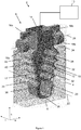
Figure 1 is a perspective view of a first example inspection device for inspecting a slot of a component; -
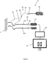
Figure 2 is a schematic view of an imaging system of the inspection device; -
Figure 3 is a flow diagram of a method performed using the inspection device; -
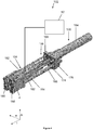
Figure 4 is a perspective view of a second example inspection device for inspecting a slot of a component; -
Figure 5 is a side view of an insert of the second example inspection device; -
Figure 6 is a side view of a support part of the insert; -
Figure 7 is a cross-sectional view of the insert positioned within the slot; -
Figure 8 is a close-up view of a portion of the insert; and -
Figure 9 is a close-up view of a portion of a jig of the second example inspection device. -
Figure 1 shows aninspection device 2 for inspecting acomponent 4 having aslot 6. Theinspection device 2 generally comprises aninsert 8 and animaging system 10. Theinsert 8 comprises aguide 12, abase 14, first andsecond arms second wheels - The
base 14 has a square cross-sectional profile. Thefirst arm 16a and thesecond arm 16b extend from opposing sides of thebase 14. Thefirst wheel 18a is attached to an end of thefirst arm 16a and thesecond wheel 18b is attached to an end of thesecond arm 16b. Theslot 6 has afirst side 17 and asecond side 19. Thefirst side 17 is a pressure side of theslot 6. Thefirst wheel 18a and thesecond wheel 18b engage with anupper surface 24 of thecomponent 4 on opposing sides of theslot 6, adjacent the first andsecond sides second wheels rotation 26 extending perpendicularly to alongitudinal axis 22 of theslot 6. - The
guide 12 extends from a lower surface of thebase 14 such that theguide 12 is supported within theslot 6. Theguide 12 is formed by acontoured plate 28. Theplate 28 comprises afirst side portion 30 and asecond side portion 32. When theguide 12 is disposed within theslot 6, thefirst side portion 30 faces thefirst side 17 of theslot 6 and thesecond side portion 32 faces thesecond side 19 of theslot 6. Theguide 12 is bounded at one of its ends by anend plate 34 and is open at its other end. - An outer surface of the
guide 12 has a cross-sectional profile substantially corresponding to and inwardly offset from the cross-sectional profile of the inner surface of theslot 6. In the example arrangement shown, thecomponent 4 is a disc of a gas turbine engine and theslot 6 forms part of a fir-tree joint. Accordingly, the inner surface of theslot 6 has a fir-tree-shaped cross-section and the outer surface of theguide 12 has a fir-tree-shaped cross-section corresponding to but slightly smaller than the fir-tree-shaped cross-section of the inner surface of theslot 6. Accordingly, agap 20 is formed between the inner surface of theslot 6 and the outer surface of theguide 12. Theguide 12 is therefore able to move along theslot 6 along thelongitudinal axis 22 of theslot 22 upon rotation of the first andsecond wheels rotation 26. Theguide 12 has a constant cross-section along its length, with the length dimension being represented by the letter I inFigure 1 . - A first plurality of holes and a second plurality of holes (not shown) extend through the
first side portion 30 of theplate 28 between ahollow interior 34 of theguide 12 and an exterior of theguide 12. The first plurality of holes are arranged along the height of theguide 12 between a lower end of theguide 12 and an upper end of theguide 12, with the height dimension being represented by the letter h inFigure 1 . The second plurality of holes are also arranged along the height of theguide 12. - A first optical fibre housing 36 (shown in grey in
Figure 1 ) is attached to each of the first plurality of holes. A bundle of firstoptical fibres Figure 1 ) configured for conveying image data is supported by each firstoptical fibre housing 36 and extends through each of the first plurality of holes. A second optical fibre housing 38 (shown in white inFigure 1 ) is attached to each of the second plurality of holes. A bundle of second optical fibres 42 (not shown inFigure 1 ) suitable for conveying light is supported by each secondoptical fibre housing 38 and extends through each of the second plurality of holes. The ends of the bundle of firstoptical fibres optical fibres 42 terminate at the outer surface of theguide 12. The bundles of firstoptical fibres optical fibres 42 are optically connected to theimaging system 10. -
Figure 2 is a schematic view of theimaging system 10 of theinspection device 2. Theimaging system 10 generally comprises animaging segment 44 and anillumination segment 46. - The
imaging segment 44 comprises the plurality of bundles of firstoptical fibres imaging segment 44 additionally comprises anobjective lens 48, aCCD camera 50, acomputer 52 and amonitor 54. Only two bundles of firstoptical fibres Figure 2 , for clarity. Theobjective lens 48 is optically connected to one of the plurality of bundles of firstoptical fibres Figure 2 , theobjective lens 48 is optically connected to the bundle of firstoptical fibres 40a. TheCCD camera 50 is positioned adjacent theobjective lens 48 so as to record optical images received therefrom. Theobjective lens 48 and theCCD camera 50 are movable between each of the plurality of bundles of firstoptical fibres Figure 2 ). TheCCD camera 50 is connected to thecomputer 52, which is in turn connected to themonitor 54. - The
illumination segment 46 comprises the plurality of bundles of secondoptical fibres 42 referred to previously. Theillumination segment 46 additionally comprises abeam splitter 56, asingle mode fibre 58, anobjective lens 60 and alaser source 62. Only two bundles of secondoptical fibres 42 are shown inFigure 2 , for clarity. Each of the plurality of bundles of secondoptical fibres 42 are optically connected to thebeam splitter 56. Thebeam splitter 56 is optically connected to theobjective lens 60 by thesingle mode fibre 58. - The operation of the
inspection device 2 will now be described with reference toFigure 3 , which shows a flow diagram of an inspection method performed using theinspection device 2, and additionally with reference toFigures 1 and2 . - During step S2, the
insert 8 is positioned within theslot 6 at a starting position as shown inFigure 1 . In the starting position, the ends of the bundles of firstoptical fibres first side 17 of theslot 6. - During step S4, the
laser source 62 generates a laser beam that passes into theobjective lens 60, along thesingle mode fibre 58 and into thebeam splitter 56. Thebeam splitter 56 splits the laser beam into multiple laser beams, each of which pass into a separate one of the plurality of bundles of secondoptical fibres 42. The laser beams pass along the plurality of bundles of secondoptical fibres 42, through the second plurality of holes extending through thefirst side portion 30 of theplate 28, and out of the ends of the plurality of bundles of secondoptical fibres 42, thereby illuminating a portion of theslot 6 adjacent the ends of the plurality of bundles of secondoptical fibres 42. - Light from the illuminated
slot 6 passes into the plurality of bundles of firstoptical fibres first side portion 30 of theplate 28 and along the plurality of bundles of firstoptical fibres optical fibres 40a passes into theobjective lens 48. Theobjective lenses 48 produces an image of the inner surface of theslot 6 adjacent the end of the bundle of firstoptical fibres 40a. The arrangement and proximity of each of the first plurality of holes ensures that fields of view of each of the plurality of bundles of firstoptical fibres - The
CCD camera 50 captures the image generated byobjective lens 48 and sends the resulting image data to thecomputer 52. Theobjective lens 48 andCCD camera 50 then move to a next bundle of first optical fibres (i.e. in the arrangement shown inFigure 2 , the bundle of firstoptical fibres 40b). TheCCD camera 50 then captures another image generated by theobjective lens 48 in this next position (i.e. an image of the inner surface of theslot 6 adjacent the end of the bundle of firstoptical fibres 40b) and sends the resulting image data to thecomputer 52. This process is repeated with theobjective lens 48 andCCD camera 50 positioned at all of the bundles of firstoptical fibres optical fibres first side 17 of theslot 6 spanning an entire height of theslot 6. Since the profile of theinsert 8 substantially corresponds to the profile of theslot 6, theinsert 8 is unable to move in the width or height direction, and, thus, the ends of the bundle of firstoptical fibres slot 6. This fixed distance allows the camera to focus. - During step S6, the
insert 8 is then actuated to a second position adjacent the starting position. In particular, theguide 12 is actuated along thelongitudinal axis 22 of theslot 6. - During step S8, step S4 is repeated such that image data is captured for a second portion of the surface of the
first side 17 of theslot 6 adjacent the first portion and spanning an entire height of theslot 6. The distance by which theinsert 8 is actuated during step S6 is small enough that the combined field of view of the plurality of the bundles of firstoptical fibres insert 8 is in the second position overlaps the combined field of view of the bundles of firstoptical fibres insert 8 is in the first position in a length direction. - Steps S6 to S8 are repeated multiple times so as to capture image data at multiple positions (i.e. n positions) along the length of the
slot 6 until image data across the entirety of the length of thefirst side 17 of theslot 6 is captured. - During step S10, the image data captured as a result of steps S2 to S8 is processed into a format suitable for analysis by a user. In particular, the images are combined into a single image using image stitching. The single image is displayed on the
monitor 54. - During step S12, a user views the image displayed on the
monitor 54. The user visually inspects the image displayed on themonitor 54. The user is able to detect any surface defects present in thefirst side 17 of the slot by looking at the image displayed on themonitor 54, such as corrosion, cracks or pits. - The
slot 6 and theguide 12 are symmetrical. Accordingly, theguide 12 can be removed from theslot 6, reversed in direction and reinserted into theslot 6 such that thefirst side portion 30 faces thesecond side 19 of theslot 6 and thesecond side portion 32 faces thefirst side 17 of theslot 6. Steps S2 to S12 can then be repeated so as to allow the user to analyse thesecond side 19 of the slot. -
Figure 4 shows analternative inspection device 102 for inspecting thecomponent 4. Theinspection device 102 generally comprises aninsert 104, ajig 106, a linear variable differential transformer (LVDT) 108 and an imaging system 10' substantially corresponding to theimaging system 10 described with reference toFigures 1 to 3 . - The same dimensional references (i.e. length I, width w and height h) are used to describe the
inspection device 102. -
Figure 5 shows theinsert 104 in isolation. Theinsert 104 comprises asupport part 110 and aninspection part 112. The support andinspection parts inspection parts support part 110 comprises arearward portion 114, amiddle portion 116 and aforward portion 118. Theinspection part 112 also comprises arearward portion 120, amiddle portion 122 and aforward portion 124. The rearward andforward portion support part 110 are narrower than themiddle portion 116. Likewise, the rearward andforward portion inspection part 112 are wider than themiddle portion 122. Accordingly, the support andinspection parts support part 110 has a first surface 125 (not shown inFigure 5 ) that abuts a first surface 127 (not shown inFigure 5 ) of theinspection part 112. Thesupport part 110 further comprises a second surface 129 (not shown inFigure 5 ) opposing the first surface of thesupport part 110 and forming a first side surface of theinsert 104. Likewise, theinspection part 112 further comprises asecond surface 126 opposing the first surface of theinspection part 112 and forming a second side surface of theinsert 104. - The
rearward portions inspection parts hole 128 extending across the width of theinsert 104. Likewise, theforward portions inspection parts insert 104. Further, therearward portions inspection parts hole 132 extending across the width of theinsert 104. Likewise, theforward portions inspection parts hole 134 extending across the width of theinsert 104. In addition, therearward portions inspection parts hole 136 extending part way along the length of theinsert 104. Likewise, theforward portions inspection parts hole 138 extending part way along the length of theinsert 104. -
Figure 6 shows thesupport part 110 in isolation with itsfirst surface 125 showing. Thefirst surface 125 has an undulating (i.e. contoured) profile. A plurality ofsemi-circular slots 140 are formed in thefirst surface 125. The plurality ofsemi-circular slots 140 extend in a heightwise direction between alip 146 and an upper surface of themiddle portion 116. Ahemispherical indentation 142 is provided in each of thesemi-circular slots 140. Each of thehemispherical indentations 142 is disposed a distinct length along its respectivesemi-circular slot 140. - Returning to
Figure 5 , the first surface of theinspection part 112 has an undulating profile corresponding to the undulating profile of thefirst surface 125 of thesupport part 110. Further, a plurality of semi-circular slots are formed in the first surface of theinspection part 112. The plurality of semi-circular slots formed in the first surface of theinspection part 112 correspond to the plurality ofsemi-circular slots 140 of the formed in thefirst surface 125 of thesupport part 110. In addition, a plurality of throughholes 144 extend through themiddle portion 122 of theinspection part 112 in a widthwise direction between the first andsecond surface inspection part 112. Each of the plurality of throughholes 144 extends from thesecond surface 126 of theinspection part 112 at a position corresponding to the position of a separate one of each of thehemispherical indentations 142. A passageway is formed by each throughhole 144 and its corresponding semi-circular slots between the upper surface of theinsert 104 and thesecond surface 126 of theinspection part 112. A camera (not shown) is disposed at the end of each of the throughholes 114, adjacent thesecond surface 126. Each of the cameras may be a "Micro ScoutCam" having a 1.2 millimetre diameter, camera resolution of approximately 49000 pixels, five optic elements, 100/130 degree field of view and 5 to 50 millimetre or 2 to 6 millimetre depth of field, for example. A camera wire (not shown) extends between each of the cameras and a computer of the imaging system 10', which corresponds to the computer of the 52 of theimaging system 10. Each of the camera wires extends through a separate one of each of the passageways. Thehemispherical indentations 142 provided in each of thesemi-circular slots 142 allows the camera wires to bend. The spacing of the throughholes 144 in the height dimension is sufficiently small that the height dimensions of each of the fields of view of the cameras overlap in the height dimension. -
Figure 7 shows a cross-sectional view of theinsert 104 within theslot 6. Thecomponent 4 shown inFigure 7 corresponds to that shown inFigure 1 . The profile of thesecond surface 129 of thesupport part 110 substantially corresponds to the profile of thesecond side 19 of theslot 6. Thelip 146 extends from a lower edge of thesupport part 110 beyond theinspection part 112. The profile of thelip 146 substantially corresponds to the profile of a lower portion of thefirst side 17 of theslot 6. The profile of thesecond surface 126 of theinspection part 112 substantially corresponds to the profile of thefirst side 17 of theslot 6 but is offset therefrom towards thefirst surface 127 such that that agap 148 is formed between thesecond surface 126 of theinspection part 112 and thefirst side 17 of theslot 6. A light 131, in particular a high intensity flexible light guide (not shown in the remaining figures), is provided at an upper surface of theinsert 104. The light 131 is oriented to direct light into theinsert 104. -
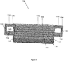
Figure 8 shows a close-up view of therearward portions inspection parts LVDT 108 comprises aprobe head 150, ashaft 152 and a housing 154 (seeFigure 4 ). Theshaft 152 extends between theprobe head 150 and thehousing 154. Theprobe head 150 is disposed within the first rectangular throughhole 128. Theshaft 152 extends through the third circular throughhole 136. Abolt 156 extends through the first circular throughhole 132 so as to secure therearward portions 114, 120 (and thus the support andinspection parts 110, 112) together and so as to secure theprobe head 150 andshaft 152 to theinsert 104. A further bolt (not shown) also extends through the second circular throughhole 134 so as to secure theforward portions - Returning to
Figure 4 , thejig 106 comprises afirst clamp 158 and asecond clamp 160. The first andsecond clamps second clamps component 4. A pair ofupper rods 162 extend from the upper end of each of the first andsecond clamps Figure 4 ) extend from the lower end of each of the first andsecond clamps lower rods 164 comprise a plurality of throughholes 166 disposed at increments along their length. - The
jig 106 further comprises aplate 168 comprising a central hole, a pair of upper throughholes 170 and a pair of lower through holes 172 (not shown inFigure 4 ). The pair ofupper rods 162 extend through the pair of upper throughholes 170 and the pair oflower rods 164 extend through the pair of lower throughholes 172. A pair offirst bolts 174 and a pair ofsecond bolts 176 extend through the throughholes 166 of each of thelower rods 164 such that theplate 168 is disposed between the pair offirst bolts 174 and the pair ofsecond bolts 176. Accordingly, the first andsecond bolts plate 168 in position relative to the first andsecond clamps component 4. The first andsecond bolts holes 166 so as to reposition theplate 168. Theplate 168 may need to be repositioned to be closer to thecomponent 4 if a shorter insert 104 (i.e. aninsert 104 having a smaller length dimension) is used, for example. -
Figure 9 shows a close-up view of the interface between theplate 168 and theLVDT 108. The upper andlower rods Figure 9 . Afirst flange 178 extends from a rear surface of theplate 168. Thefirst flange 178 is arc-shaped in cross-section and has a radius equivalent to the radius of thehousing 154 of theLVDT 108. Asecond arm 180 also extends from a rear surface of the plate 74. Thesecond arm 180 comprises a threadedhole 182 through which abolt 184 extends. An end of thebolt 184 is supported within arecess 186 of asupport member 188. Thesupport member 188 comprises a surface having an arc-shaped cross-section with a radius equivalent to the radius of thehousing 154 of theLVDT 54. - The
housing 154 of theLVDT 108 is positioned between thefirst flange 178 and thesupport member 188 such that theshaft 152 of theLVDT 108 extends through the central hole of theplate 168 and thehousing 154 abuts theplate 168. Thebolt 184 is rotated within the threadedhole 182 so as to actuate thesupport member 188 towards thehousing 154 and secure thehousing 154 in place relative to theplate 168. Theshaft 152 of theLVDT 108 is linearly actuable relative to thehousing 154 such that theshaft 152 is able to move linearly through the central hole. The extent of actuation of theLVDT 108 determines the position of theinsert 104 within theslot 6. - As mentioned above, the imaging system 10' of the
alternative inspection device 102 substantially corresponds to theimaging system 10 of theinspection device 2. However, the illumination segment of the imaging system 10' comprises the light 131, thesupport part 110 and theinspection part 112 rather than the components of theillumination segment 46 referred to previously. - The operation of the
alternative device 102 substantially corresponds to the operation of theinspection device 2, with some minor differences. For example, during step S2, thejig 106 is attached to thecomponent 4 and theLVDT 108 is actuated to a starting position such that theinsert 104 is in a starting position. During step S4, theslot 6 is illuminated by switching on the light 131. In particular, light emitted from the light 131 enters the transparent support andinspection parts inspection parts inspection parts slot 6. The light entering the support andinspection parts inspection parts inspection parts LVDT 108 to a second position (and subsequent positions) such that theinsert 104 is in a second position (and subsequent positions). - Although it has been described that the
inspection devices slot 6 having a fir-tree-shaped cross-section, theinspection devices slots 6 having any cross-sectional profile. In such arrangements, theinserts slots 6. Theinspection devices - Although it has been described that the
guide 12 is bounded at one of its ends by anend plate 32 and is open at its other end, theguide 12 may alternatively be bounded at both of its ends by opposing end plates or be open at both of its ends. - Although it has been described that the
inspection device 2 illuminates a portion of theslot 6 by way of a plurality of bundles of secondoptical fibres 42, theinsert 8 may instead be wholly or partially transparent such that it acts as a light guide, as per theinsert 104 of theinspection device 102. Further, although it has been described that theinsert 104 of theinspection device 102 acts as a light guide, theinsert 102 may instead be provided with a plurality of bundles of second optical fibres to illuminate theslot 6, as per theinsert 8 of theinspection device 2. - It has been described that the
component 4 is a disc of a gas turbine engine. However, theinspection devices component 4. For example, theinspection devices - In the example arrangement shown, the
component 4 is a disc of a gas turbine engine and theslot 6 forms part of a fir-tree joint. - Although it has been described with reference to the
inspection device 2 that a laser is used to illuminate theslot 6, any type of illumination source may be used. Further, any type of fibres may be used. The illumination source and/or the fibres may be selected in order to illuminate theslot 6 with a particular wavelength or wavelengths of light. - In alternative arrangements, fluorescent penetrant inspection can additionally be used to inspect the
slot 6 of thecomponent 4. In such arrangements the light source is an ultraviolet light source and theslot 6 is illuminated with ultraviolet light. - Although it has been described that all of the image data of the
slot 6 is gathered before being displayed on themonitor 54, the image data may alternatively be displayed on themonitor 54 in real-time. Snapshots of the image data may be taken in real-time. - It has been described that during step S10, the images are combined into a single image using image stitching. However, in alternative arrangements the images are not combined into a single image and are instead presented separately on the
monitor 54. - The abovementioned steps of operation of the
devices
Claims (15)
- An inspection device for inspecting a slot of a gas turbine engine, the inspection device comprising:an insert for insertion into the slot;a plurality of imaging devices coupled to the insert; anda processor;wherein the insert is movable along a longitudinal axis of the slot;
wherein each of the plurality of imaging devices is positioned adjacent an external surface of the insert and is configured to capture an image of a portion of the slot adjacent the imaging device; and
wherein the processor is configured to receive data corresponding to the images captured by the plurality of imaging devices. - An inspection device as claimed in claim 1, wherein the insert has an external profile, a portion of which corresponds to an internal profile of the slot.
- An inspection device as claimed in claim 1 or 2, wherein the slot is a fir-tree slot.
- An inspection device as claimed in any preceding claim, wherein the plurality of imaging devices are arranged at multiple heights along the insert.
- An inspection device as claimed in any preceding claim, wherein each of the imaging devices has a field of view and wherein the total field of view of the imaging devices spans substantially an entire height of the slot.
- An inspection device as claimed in any preceding claim, further comprising a plurality of illumination devices coupled to the insert and positioned adjacent an external surface of the insert, wherein each of the plurality of illumination devices is configured to illuminate a portion of the slot adjacent the illumination device.
- An inspection device as claimed in any preceding claim, wherein the insert is substantially transparent and acts as a light guide.
- An inspection device as claimed in any preceding claim, wherein each of the imaging devices comprises a bundle of optical fibres.
- An inspection device as claimed in any preceding claim, wherein each of the imaging devices comprises a camera disposed adjacent the external surface of the insert.
- An inspection device as claimed in any preceding claim, wherein the processor is configured to generate a single image from the data.
- An inspection device as claimed in any preceding claim, further comprising a display configured to display images based on the data.
- A method of inspecting a slot using the inspection device of claim 1, the method comprising:inserting the insert into the slot at a first position;capturing an image using each of the imaging devices with the insert at the first position;moving the insert to one or more further positions; andcapturing an image using each of the imaging devices with the insert at the one or more further positions.
- A method of inspecting a slot as claimed in claim 12, further comprising illuminating the slot using one or more illumination devices.
- A method of inspecting a slot as claimed in claim 12 or 13, wherein images of the entire length and height of at least one side of the slot are captured.
- A method of inspecting a slot as claimed in 14, wherein a single image of the entire length and height of the slot is generated based on the images.
Applications Claiming Priority (1)
| Application Number | Priority Date | Filing Date | Title |
|---|---|---|---|
| GB1802693.0A GB2577851A (en) | 2018-02-20 | 2018-02-20 | An inspection device and method of inspecting a slot |
Publications (2)
| Publication Number | Publication Date |
|---|---|
| EP3527974A1 true EP3527974A1 (en) | 2019-08-21 |
| EP3527974B1 EP3527974B1 (en) | 2023-05-17 |
Family
ID=61783680
Family Applications (1)
| Application Number | Title | Priority Date | Filing Date |
|---|---|---|---|
| EP19152940.3A Active EP3527974B1 (en) | 2018-02-20 | 2019-01-22 | Inspection devices and methods of inspecting a slot |
Country Status (4)
| Country | Link |
|---|---|
| US (1) | US10809203B2 (en) |
| EP (1) | EP3527974B1 (en) |
| GB (1) | GB2577851A (en) |
| SG (1) | SG10201900630YA (en) |
Cited By (1)
| Publication number | Priority date | Publication date | Assignee | Title |
|---|---|---|---|---|
| US20240112350A1 (en) * | 2022-10-03 | 2024-04-04 | Ford Global Technologies, Llc | Methods and systems for non-destructive evaluation of stator insulation condition |
Families Citing this family (1)
| Publication number | Priority date | Publication date | Assignee | Title |
|---|---|---|---|---|
| US12126225B2 (en) * | 2022-03-09 | 2024-10-22 | GM Global Technology Operations LLC | Optical inspection of stator slots |
Citations (3)
| Publication number | Priority date | Publication date | Assignee | Title |
|---|---|---|---|---|
| US20080245980A1 (en) * | 2007-04-05 | 2008-10-09 | Siemens Power Generation, Inc. | Monitoring system for turbine engine |
| EP2597273A2 (en) * | 2011-11-28 | 2013-05-29 | Rolls-Royce plc | An apparatus and a method of inspecting a turbomachine |
| US20160239955A1 (en) * | 2015-02-13 | 2016-08-18 | Rolls-Royce Plc | Apparatus and a method of machining a shape through a component |
Family Cites Families (8)
| Publication number | Priority date | Publication date | Assignee | Title |
|---|---|---|---|---|
| US2607267A (en) | 1950-03-29 | 1952-08-19 | Eastman Kodak Co | Optical system for the inspection of curved profiles |
| US2747463A (en) | 1950-12-18 | 1956-05-29 | Power Jets Res & Dev Ltd | Optical inspection device |
| US6545467B1 (en) | 2000-10-27 | 2003-04-08 | General Electric Company | Contoured surface eddy current inspection system |
| US7684134B2 (en) * | 2003-01-21 | 2010-03-23 | The General Hospital Corporation | Microscope objectives |
| GB0917410D0 (en) * | 2009-10-06 | 2009-11-18 | Rolls Royce Plc | Method for forming a pressure measurement in a component |
| EP2679778B1 (en) | 2012-06-27 | 2019-08-21 | Ansaldo Energia IP UK Limited | A method for measuring geometry deformations of a turbine component |
| CA2906339A1 (en) * | 2013-03-15 | 2014-09-25 | Mohammad JALILIAN | Borescope apparatus and a method of using same |
| US11111813B2 (en) * | 2016-12-06 | 2021-09-07 | General Electric Company | Gas turbine engine maintenance method |
-
2018
- 2018-02-20 GB GB1802693.0A patent/GB2577851A/en not_active Withdrawn
-
2019
- 2019-01-22 EP EP19152940.3A patent/EP3527974B1/en active Active
- 2019-01-24 SG SG10201900630YA patent/SG10201900630YA/en unknown
- 2019-01-29 US US16/260,186 patent/US10809203B2/en active Active
Patent Citations (3)
| Publication number | Priority date | Publication date | Assignee | Title |
|---|---|---|---|---|
| US20080245980A1 (en) * | 2007-04-05 | 2008-10-09 | Siemens Power Generation, Inc. | Monitoring system for turbine engine |
| EP2597273A2 (en) * | 2011-11-28 | 2013-05-29 | Rolls-Royce plc | An apparatus and a method of inspecting a turbomachine |
| US20160239955A1 (en) * | 2015-02-13 | 2016-08-18 | Rolls-Royce Plc | Apparatus and a method of machining a shape through a component |
Cited By (2)
| Publication number | Priority date | Publication date | Assignee | Title |
|---|---|---|---|---|
| US20240112350A1 (en) * | 2022-10-03 | 2024-04-04 | Ford Global Technologies, Llc | Methods and systems for non-destructive evaluation of stator insulation condition |
| US12437415B2 (en) * | 2022-10-03 | 2025-10-07 | Ford Global Technologies, Llc | Methods and systems for non-destructive evaluation of stator insulation condition |
Also Published As
| Publication number | Publication date |
|---|---|
| GB2577851A (en) | 2020-04-15 |
| SG10201900630YA (en) | 2019-09-27 |
| US10809203B2 (en) | 2020-10-20 |
| US20190257764A1 (en) | 2019-08-22 |
| EP3527974B1 (en) | 2023-05-17 |
| GB201802693D0 (en) | 2018-04-04 |
Similar Documents
| Publication | Publication Date | Title |
|---|---|---|
| EP2403396B1 (en) | Wavefront analysis inspection apparatus and method | |
| US7554572B2 (en) | Image pickup apparatus for capturing spectral images of an object and observation system including the same | |
| US10184858B2 (en) | Visually inspecting optical fibers | |
| US8823930B2 (en) | Apparatus and method for inspecting an object | |
| CN1127758C (en) | Method and apparatus for visually inspecting object | |
| KR20050084110A (en) | An apparatus and method for detecting surface defects on a workpiece such as a rolled/drawn metal bar | |
| EP0694756A2 (en) | Elongation measurement using a laser non-contact extensometer | |
| KR101523336B1 (en) | apparatus for examining pattern image of semiconductor wafer | |
| EP3527974B1 (en) | Inspection devices and methods of inspecting a slot | |
| JP2001194133A (en) | Method and apparatus for measuring concentricity of cylindrical parts | |
| CN101603926B (en) | Multi-surface detection system and method | |
| US20250347904A1 (en) | Directing light into an optical fiber | |
| CN1153058C (en) | Through hole inspecting method and device | |
| US6929604B2 (en) | Optic for industrial endoscope/borescope with narrow field of view and low distortion | |
| EP1978353A2 (en) | Multiple surface inspection system and method | |
| EP4170280A1 (en) | Method and device for monitoring the shape of hard-to-reach components | |
| JP5281815B2 (en) | Optical device defect inspection method and optical device defect inspection apparatus | |
| US20120105869A1 (en) | Three dimensional inspection and metrology based on short pulses of light | |
| US20230241710A1 (en) | Method for Analyzing a Workpiece Surface for a Laser Machining Process and Analysis Device for Analyzing a Workpiece Surface | |
| JP4608399B2 (en) | Inspection device for illumination optical element | |
| JPH06225225A (en) | Method and apparatus for improving resolution of image | |
| KR102737491B1 (en) | Optical system of an inspection device | |
| JPH1164159A (en) | Inspection method and inspection apparatus for surface of phase grating | |
| KR20110090381A (en) | Visual inspection device | |
| DE102007024684A1 (en) | Three-dimensional structure i.e. thin course, detecting method for sheet metal of vehicle body, involves obtaining information about structure from brightness difference of two-dimensional images produced by optical viewing device |
Legal Events
| Date | Code | Title | Description |
|---|---|---|---|
| PUAI | Public reference made under article 153(3) epc to a published international application that has entered the european phase |
Free format text: ORIGINAL CODE: 0009012 |
|
| STAA | Information on the status of an ep patent application or granted ep patent |
Free format text: STATUS: THE APPLICATION HAS BEEN PUBLISHED |
|
| AK | Designated contracting states |
Kind code of ref document: A1 Designated state(s): AL AT BE BG CH CY CZ DE DK EE ES FI FR GB GR HR HU IE IS IT LI LT LU LV MC MK MT NL NO PL PT RO RS SE SI SK SM TR |
|
| AX | Request for extension of the european patent |
Extension state: BA ME |
|
| STAA | Information on the status of an ep patent application or granted ep patent |
Free format text: STATUS: REQUEST FOR EXAMINATION WAS MADE |
|
| 17P | Request for examination filed |
Effective date: 20200106 |
|
| RBV | Designated contracting states (corrected) |
Designated state(s): AL AT BE BG CH CY CZ DE DK EE ES FI FR GB GR HR HU IE IS IT LI LT LU LV MC MK MT NL NO PL PT RO RS SE SI SK SM TR |
|
| RAP1 | Party data changed (applicant data changed or rights of an application transferred) |
Owner name: ROLLS-ROYCE PLC |
|
| STAA | Information on the status of an ep patent application or granted ep patent |
Free format text: STATUS: EXAMINATION IS IN PROGRESS |
|
| 17Q | First examination report despatched |
Effective date: 20211201 |
|
| GRAP | Despatch of communication of intention to grant a patent |
Free format text: ORIGINAL CODE: EPIDOSNIGR1 |
|
| STAA | Information on the status of an ep patent application or granted ep patent |
Free format text: STATUS: GRANT OF PATENT IS INTENDED |
|
| INTG | Intention to grant announced |
Effective date: 20230301 |
|
| GRAS | Grant fee paid |
Free format text: ORIGINAL CODE: EPIDOSNIGR3 |
|
| GRAA | (expected) grant |
Free format text: ORIGINAL CODE: 0009210 |
|
| STAA | Information on the status of an ep patent application or granted ep patent |
Free format text: STATUS: THE PATENT HAS BEEN GRANTED |
|
| AK | Designated contracting states |
Kind code of ref document: B1 Designated state(s): AL AT BE BG CH CY CZ DE DK EE ES FI FR GB GR HR HU IE IS IT LI LT LU LV MC MK MT NL NO PL PT RO RS SE SI SK SM TR |
|
| REG | Reference to a national code |
Ref country code: GB Ref legal event code: FG4D |
|
| REG | Reference to a national code |
Ref country code: CH Ref legal event code: EP |
|
| REG | Reference to a national code |
Ref country code: DE Ref legal event code: R096 Ref document number: 602019028994 Country of ref document: DE |
|
| REG | Reference to a national code |
Ref country code: IE Ref legal event code: FG4D |
|
| REG | Reference to a national code |
Ref country code: AT Ref legal event code: REF Ref document number: 1568576 Country of ref document: AT Kind code of ref document: T Effective date: 20230615 |
|
| P01 | Opt-out of the competence of the unified patent court (upc) registered |
Effective date: 20230528 |
|
| REG | Reference to a national code |
Ref country code: LT Ref legal event code: MG9D |
|
| REG | Reference to a national code |
Ref country code: NL Ref legal event code: MP Effective date: 20230517 |
|
| REG | Reference to a national code |
Ref country code: AT Ref legal event code: MK05 Ref document number: 1568576 Country of ref document: AT Kind code of ref document: T Effective date: 20230517 |
|
| PG25 | Lapsed in a contracting state [announced via postgrant information from national office to epo] |
Ref country code: SE Free format text: LAPSE BECAUSE OF FAILURE TO SUBMIT A TRANSLATION OF THE DESCRIPTION OR TO PAY THE FEE WITHIN THE PRESCRIBED TIME-LIMIT Effective date: 20230517 Ref country code: PT Free format text: LAPSE BECAUSE OF FAILURE TO SUBMIT A TRANSLATION OF THE DESCRIPTION OR TO PAY THE FEE WITHIN THE PRESCRIBED TIME-LIMIT Effective date: 20230918 Ref country code: NO Free format text: LAPSE BECAUSE OF FAILURE TO SUBMIT A TRANSLATION OF THE DESCRIPTION OR TO PAY THE FEE WITHIN THE PRESCRIBED TIME-LIMIT Effective date: 20230817 Ref country code: NL Free format text: LAPSE BECAUSE OF FAILURE TO SUBMIT A TRANSLATION OF THE DESCRIPTION OR TO PAY THE FEE WITHIN THE PRESCRIBED TIME-LIMIT Effective date: 20230517 Ref country code: ES Free format text: LAPSE BECAUSE OF FAILURE TO SUBMIT A TRANSLATION OF THE DESCRIPTION OR TO PAY THE FEE WITHIN THE PRESCRIBED TIME-LIMIT Effective date: 20230517 Ref country code: AT Free format text: LAPSE BECAUSE OF FAILURE TO SUBMIT A TRANSLATION OF THE DESCRIPTION OR TO PAY THE FEE WITHIN THE PRESCRIBED TIME-LIMIT Effective date: 20230517 |
|
| PG25 | Lapsed in a contracting state [announced via postgrant information from national office to epo] |
Ref country code: RS Free format text: LAPSE BECAUSE OF FAILURE TO SUBMIT A TRANSLATION OF THE DESCRIPTION OR TO PAY THE FEE WITHIN THE PRESCRIBED TIME-LIMIT Effective date: 20230517 Ref country code: PL Free format text: LAPSE BECAUSE OF FAILURE TO SUBMIT A TRANSLATION OF THE DESCRIPTION OR TO PAY THE FEE WITHIN THE PRESCRIBED TIME-LIMIT Effective date: 20230517 Ref country code: LV Free format text: LAPSE BECAUSE OF FAILURE TO SUBMIT A TRANSLATION OF THE DESCRIPTION OR TO PAY THE FEE WITHIN THE PRESCRIBED TIME-LIMIT Effective date: 20230517 Ref country code: LT Free format text: LAPSE BECAUSE OF FAILURE TO SUBMIT A TRANSLATION OF THE DESCRIPTION OR TO PAY THE FEE WITHIN THE PRESCRIBED TIME-LIMIT Effective date: 20230517 Ref country code: IS Free format text: LAPSE BECAUSE OF FAILURE TO SUBMIT A TRANSLATION OF THE DESCRIPTION OR TO PAY THE FEE WITHIN THE PRESCRIBED TIME-LIMIT Effective date: 20230917 Ref country code: HR Free format text: LAPSE BECAUSE OF FAILURE TO SUBMIT A TRANSLATION OF THE DESCRIPTION OR TO PAY THE FEE WITHIN THE PRESCRIBED TIME-LIMIT Effective date: 20230517 Ref country code: GR Free format text: LAPSE BECAUSE OF FAILURE TO SUBMIT A TRANSLATION OF THE DESCRIPTION OR TO PAY THE FEE WITHIN THE PRESCRIBED TIME-LIMIT Effective date: 20230818 |
|
| PG25 | Lapsed in a contracting state [announced via postgrant information from national office to epo] |
Ref country code: FI Free format text: LAPSE BECAUSE OF FAILURE TO SUBMIT A TRANSLATION OF THE DESCRIPTION OR TO PAY THE FEE WITHIN THE PRESCRIBED TIME-LIMIT Effective date: 20230517 |
|
| PG25 | Lapsed in a contracting state [announced via postgrant information from national office to epo] |
Ref country code: SK Free format text: LAPSE BECAUSE OF FAILURE TO SUBMIT A TRANSLATION OF THE DESCRIPTION OR TO PAY THE FEE WITHIN THE PRESCRIBED TIME-LIMIT Effective date: 20230517 |
|
| PG25 | Lapsed in a contracting state [announced via postgrant information from national office to epo] |
Ref country code: SM Free format text: LAPSE BECAUSE OF FAILURE TO SUBMIT A TRANSLATION OF THE DESCRIPTION OR TO PAY THE FEE WITHIN THE PRESCRIBED TIME-LIMIT Effective date: 20230517 Ref country code: SK Free format text: LAPSE BECAUSE OF FAILURE TO SUBMIT A TRANSLATION OF THE DESCRIPTION OR TO PAY THE FEE WITHIN THE PRESCRIBED TIME-LIMIT Effective date: 20230517 Ref country code: RO Free format text: LAPSE BECAUSE OF FAILURE TO SUBMIT A TRANSLATION OF THE DESCRIPTION OR TO PAY THE FEE WITHIN THE PRESCRIBED TIME-LIMIT Effective date: 20230517 Ref country code: EE Free format text: LAPSE BECAUSE OF FAILURE TO SUBMIT A TRANSLATION OF THE DESCRIPTION OR TO PAY THE FEE WITHIN THE PRESCRIBED TIME-LIMIT Effective date: 20230517 Ref country code: DK Free format text: LAPSE BECAUSE OF FAILURE TO SUBMIT A TRANSLATION OF THE DESCRIPTION OR TO PAY THE FEE WITHIN THE PRESCRIBED TIME-LIMIT Effective date: 20230517 Ref country code: CZ Free format text: LAPSE BECAUSE OF FAILURE TO SUBMIT A TRANSLATION OF THE DESCRIPTION OR TO PAY THE FEE WITHIN THE PRESCRIBED TIME-LIMIT Effective date: 20230517 |
|
| REG | Reference to a national code |
Ref country code: DE Ref legal event code: R097 Ref document number: 602019028994 Country of ref document: DE |
|
| PLBE | No opposition filed within time limit |
Free format text: ORIGINAL CODE: 0009261 |
|
| STAA | Information on the status of an ep patent application or granted ep patent |
Free format text: STATUS: NO OPPOSITION FILED WITHIN TIME LIMIT |
|
| 26N | No opposition filed |
Effective date: 20240220 |
|
| PG25 | Lapsed in a contracting state [announced via postgrant information from national office to epo] |
Ref country code: SI Free format text: LAPSE BECAUSE OF FAILURE TO SUBMIT A TRANSLATION OF THE DESCRIPTION OR TO PAY THE FEE WITHIN THE PRESCRIBED TIME-LIMIT Effective date: 20230517 |
|
| PG25 | Lapsed in a contracting state [announced via postgrant information from national office to epo] |
Ref country code: SI Free format text: LAPSE BECAUSE OF FAILURE TO SUBMIT A TRANSLATION OF THE DESCRIPTION OR TO PAY THE FEE WITHIN THE PRESCRIBED TIME-LIMIT Effective date: 20230517 Ref country code: IT Free format text: LAPSE BECAUSE OF FAILURE TO SUBMIT A TRANSLATION OF THE DESCRIPTION OR TO PAY THE FEE WITHIN THE PRESCRIBED TIME-LIMIT Effective date: 20230517 |
|
| PG25 | Lapsed in a contracting state [announced via postgrant information from national office to epo] |
Ref country code: MC Free format text: LAPSE BECAUSE OF FAILURE TO SUBMIT A TRANSLATION OF THE DESCRIPTION OR TO PAY THE FEE WITHIN THE PRESCRIBED TIME-LIMIT Effective date: 20230517 |
|
| PG25 | Lapsed in a contracting state [announced via postgrant information from national office to epo] |
Ref country code: MC Free format text: LAPSE BECAUSE OF FAILURE TO SUBMIT A TRANSLATION OF THE DESCRIPTION OR TO PAY THE FEE WITHIN THE PRESCRIBED TIME-LIMIT Effective date: 20230517 |
|
| REG | Reference to a national code |
Ref country code: CH Ref legal event code: PL |
|
| PG25 | Lapsed in a contracting state [announced via postgrant information from national office to epo] |
Ref country code: LU Free format text: LAPSE BECAUSE OF NON-PAYMENT OF DUE FEES Effective date: 20240122 |
|
| PG25 | Lapsed in a contracting state [announced via postgrant information from national office to epo] |
Ref country code: LU Free format text: LAPSE BECAUSE OF NON-PAYMENT OF DUE FEES Effective date: 20240122 |
|
| PG25 | Lapsed in a contracting state [announced via postgrant information from national office to epo] |
Ref country code: BE Free format text: LAPSE BECAUSE OF NON-PAYMENT OF DUE FEES Effective date: 20240131 |
|
| PG25 | Lapsed in a contracting state [announced via postgrant information from national office to epo] |
Ref country code: CH Free format text: LAPSE BECAUSE OF NON-PAYMENT OF DUE FEES Effective date: 20240131 |
|
| PG25 | Lapsed in a contracting state [announced via postgrant information from national office to epo] |
Ref country code: CH Free format text: LAPSE BECAUSE OF NON-PAYMENT OF DUE FEES Effective date: 20240131 Ref country code: BE Free format text: LAPSE BECAUSE OF NON-PAYMENT OF DUE FEES Effective date: 20240131 |
|
| REG | Reference to a national code |
Ref country code: BE Ref legal event code: MM Effective date: 20240131 |
|
| PG25 | Lapsed in a contracting state [announced via postgrant information from national office to epo] |
Ref country code: BG Free format text: LAPSE BECAUSE OF FAILURE TO SUBMIT A TRANSLATION OF THE DESCRIPTION OR TO PAY THE FEE WITHIN THE PRESCRIBED TIME-LIMIT Effective date: 20230517 |
|
| PG25 | Lapsed in a contracting state [announced via postgrant information from national office to epo] |
Ref country code: BG Free format text: LAPSE BECAUSE OF FAILURE TO SUBMIT A TRANSLATION OF THE DESCRIPTION OR TO PAY THE FEE WITHIN THE PRESCRIBED TIME-LIMIT Effective date: 20230517 |
|
| PG25 | Lapsed in a contracting state [announced via postgrant information from national office to epo] |
Ref country code: IE Free format text: LAPSE BECAUSE OF NON-PAYMENT OF DUE FEES Effective date: 20240122 |
|
| PG25 | Lapsed in a contracting state [announced via postgrant information from national office to epo] |
Ref country code: IE Free format text: LAPSE BECAUSE OF NON-PAYMENT OF DUE FEES Effective date: 20240122 |
|
| PG25 | Lapsed in a contracting state [announced via postgrant information from national office to epo] |
Ref country code: CY Free format text: LAPSE BECAUSE OF FAILURE TO SUBMIT A TRANSLATION OF THE DESCRIPTION OR TO PAY THE FEE WITHIN THE PRESCRIBED TIME-LIMIT; INVALID AB INITIO Effective date: 20190122 |
|
| PG25 | Lapsed in a contracting state [announced via postgrant information from national office to epo] |
Ref country code: HU Free format text: LAPSE BECAUSE OF FAILURE TO SUBMIT A TRANSLATION OF THE DESCRIPTION OR TO PAY THE FEE WITHIN THE PRESCRIBED TIME-LIMIT; INVALID AB INITIO Effective date: 20190122 |
|
| PG25 | Lapsed in a contracting state [announced via postgrant information from national office to epo] |
Ref country code: TR Free format text: LAPSE BECAUSE OF FAILURE TO SUBMIT A TRANSLATION OF THE DESCRIPTION OR TO PAY THE FEE WITHIN THE PRESCRIBED TIME-LIMIT Effective date: 20230517 |
|
| PGFP | Annual fee paid to national office [announced via postgrant information from national office to epo] |
Ref country code: GB Payment date: 20260126 Year of fee payment: 8 |
|
| PGFP | Annual fee paid to national office [announced via postgrant information from national office to epo] |
Ref country code: DE Payment date: 20260127 Year of fee payment: 8 |
|
| PGFP | Annual fee paid to national office [announced via postgrant information from national office to epo] |
Ref country code: FR Payment date: 20260126 Year of fee payment: 8 |