EP3527946B1 - Method and system for real-time generation of reference navigation path for navigation of vehicle - Google Patents
Method and system for real-time generation of reference navigation path for navigation of vehicle Download PDFInfo
- Publication number
- EP3527946B1 EP3527946B1 EP18164925.2A EP18164925A EP3527946B1 EP 3527946 B1 EP3527946 B1 EP 3527946B1 EP 18164925 A EP18164925 A EP 18164925A EP 3527946 B1 EP3527946 B1 EP 3527946B1
- Authority
- EP
- European Patent Office
- Prior art keywords
- path
- vehicle
- road vehicle
- navigation path
- navigation
- Prior art date
- Legal status (The legal status is an assumption and is not a legal conclusion. Google has not performed a legal analysis and makes no representation as to the accuracy of the status listed.)
- Active
Links
Images




Classifications
-
- G—PHYSICS
- G05—CONTROLLING; REGULATING
- G05D—SYSTEMS FOR CONTROLLING OR REGULATING NON-ELECTRIC VARIABLES
- G05D1/00—Control of position, course, altitude or attitude of land, water, air or space vehicles, e.g. using automatic pilots
- G05D1/02—Control of position or course in two dimensions
- G05D1/021—Control of position or course in two dimensions specially adapted to land vehicles
- G05D1/0212—Control of position or course in two dimensions specially adapted to land vehicles with means for defining a desired trajectory
- G05D1/0217—Control of position or course in two dimensions specially adapted to land vehicles with means for defining a desired trajectory in accordance with energy consumption, time reduction or distance reduction criteria
-
- B—PERFORMING OPERATIONS; TRANSPORTING
- B60—VEHICLES IN GENERAL
- B60W—CONJOINT CONTROL OF VEHICLE SUB-UNITS OF DIFFERENT TYPE OR DIFFERENT FUNCTION; CONTROL SYSTEMS SPECIALLY ADAPTED FOR HYBRID VEHICLES; ROAD VEHICLE DRIVE CONTROL SYSTEMS FOR PURPOSES NOT RELATED TO THE CONTROL OF A PARTICULAR SUB-UNIT
- B60W30/00—Purposes of road vehicle drive control systems not related to the control of a particular sub-unit, e.g. of systems using conjoint control of vehicle sub-units
-
- B—PERFORMING OPERATIONS; TRANSPORTING
- B60—VEHICLES IN GENERAL
- B60W—CONJOINT CONTROL OF VEHICLE SUB-UNITS OF DIFFERENT TYPE OR DIFFERENT FUNCTION; CONTROL SYSTEMS SPECIALLY ADAPTED FOR HYBRID VEHICLES; ROAD VEHICLE DRIVE CONTROL SYSTEMS FOR PURPOSES NOT RELATED TO THE CONTROL OF A PARTICULAR SUB-UNIT
- B60W60/00—Drive control systems specially adapted for autonomous road vehicles
- B60W60/001—Planning or execution of driving tasks
- B60W60/0015—Planning or execution of driving tasks specially adapted for safety
- B60W60/0016—Planning or execution of driving tasks specially adapted for safety of the vehicle or its occupants
-
- G—PHYSICS
- G01—MEASURING; TESTING
- G01C—MEASURING DISTANCES, LEVELS OR BEARINGS; SURVEYING; NAVIGATION; GYROSCOPIC INSTRUMENTS; PHOTOGRAMMETRY OR VIDEOGRAMMETRY
- G01C21/00—Navigation; Navigational instruments not provided for in groups G01C1/00 - G01C19/00
- G01C21/26—Navigation; Navigational instruments not provided for in groups G01C1/00 - G01C19/00 specially adapted for navigation in a road network
-
- G—PHYSICS
- G01—MEASURING; TESTING
- G01C—MEASURING DISTANCES, LEVELS OR BEARINGS; SURVEYING; NAVIGATION; GYROSCOPIC INSTRUMENTS; PHOTOGRAMMETRY OR VIDEOGRAMMETRY
- G01C21/00—Navigation; Navigational instruments not provided for in groups G01C1/00 - G01C19/00
- G01C21/26—Navigation; Navigational instruments not provided for in groups G01C1/00 - G01C19/00 specially adapted for navigation in a road network
- G01C21/34—Route searching; Route guidance
- G01C21/3407—Route searching; Route guidance specially adapted for specific applications
- G01C21/3415—Dynamic re-routing, e.g. recalculating the route when the user deviates from calculated route or after detecting real-time traffic data or accidents
-
- G—PHYSICS
- G05—CONTROLLING; REGULATING
- G05D—SYSTEMS FOR CONTROLLING OR REGULATING NON-ELECTRIC VARIABLES
- G05D1/00—Control of position, course, altitude or attitude of land, water, air or space vehicles, e.g. using automatic pilots
- G05D1/02—Control of position or course in two dimensions
- G05D1/021—Control of position or course in two dimensions specially adapted to land vehicles
- G05D1/0212—Control of position or course in two dimensions specially adapted to land vehicles with means for defining a desired trajectory
- G05D1/0214—Control of position or course in two dimensions specially adapted to land vehicles with means for defining a desired trajectory in accordance with safety or protection criteria, e.g. avoiding hazardous areas
-
- B—PERFORMING OPERATIONS; TRANSPORTING
- B60—VEHICLES IN GENERAL
- B60W—CONJOINT CONTROL OF VEHICLE SUB-UNITS OF DIFFERENT TYPE OR DIFFERENT FUNCTION; CONTROL SYSTEMS SPECIALLY ADAPTED FOR HYBRID VEHICLES; ROAD VEHICLE DRIVE CONTROL SYSTEMS FOR PURPOSES NOT RELATED TO THE CONTROL OF A PARTICULAR SUB-UNIT
- B60W2420/00—Indexing codes relating to the type of sensors based on the principle of their operation
- B60W2420/40—Photo, light or radio wave sensitive means, e.g. infrared sensors
- B60W2420/403—Image sensing, e.g. optical camera
-
- B—PERFORMING OPERATIONS; TRANSPORTING
- B60—VEHICLES IN GENERAL
- B60W—CONJOINT CONTROL OF VEHICLE SUB-UNITS OF DIFFERENT TYPE OR DIFFERENT FUNCTION; CONTROL SYSTEMS SPECIALLY ADAPTED FOR HYBRID VEHICLES; ROAD VEHICLE DRIVE CONTROL SYSTEMS FOR PURPOSES NOT RELATED TO THE CONTROL OF A PARTICULAR SUB-UNIT
- B60W2420/00—Indexing codes relating to the type of sensors based on the principle of their operation
- B60W2420/40—Photo, light or radio wave sensitive means, e.g. infrared sensors
- B60W2420/408—Radar; Laser, e.g. lidar
-
- B—PERFORMING OPERATIONS; TRANSPORTING
- B60—VEHICLES IN GENERAL
- B60W—CONJOINT CONTROL OF VEHICLE SUB-UNITS OF DIFFERENT TYPE OR DIFFERENT FUNCTION; CONTROL SYSTEMS SPECIALLY ADAPTED FOR HYBRID VEHICLES; ROAD VEHICLE DRIVE CONTROL SYSTEMS FOR PURPOSES NOT RELATED TO THE CONTROL OF A PARTICULAR SUB-UNIT
- B60W2552/00—Input parameters relating to infrastructure
- B60W2552/15—Road slope, i.e. the inclination of a road segment in the longitudinal direction
-
- B—PERFORMING OPERATIONS; TRANSPORTING
- B60—VEHICLES IN GENERAL
- B60W—CONJOINT CONTROL OF VEHICLE SUB-UNITS OF DIFFERENT TYPE OR DIFFERENT FUNCTION; CONTROL SYSTEMS SPECIALLY ADAPTED FOR HYBRID VEHICLES; ROAD VEHICLE DRIVE CONTROL SYSTEMS FOR PURPOSES NOT RELATED TO THE CONTROL OF A PARTICULAR SUB-UNIT
- B60W2552/00—Input parameters relating to infrastructure
- B60W2552/30—Road curve radius
-
- G—PHYSICS
- G06—COMPUTING OR CALCULATING; COUNTING
- G06F—ELECTRIC DIGITAL DATA PROCESSING
- G06F16/00—Information retrieval; Database structures therefor; File system structures therefor
- G06F16/20—Information retrieval; Database structures therefor; File system structures therefor of structured data, e.g. relational data
- G06F16/22—Indexing; Data structures therefor; Storage structures
Definitions
- the present subject matter relates generally to field of telematics, and more particularly, but not exclusively to a method and a system for generating a reference navigation path in real-time for safe navigation of a vehicle.
- the autonomous vehicle technology aims to reduce energy consumption, pollution, reduce frequency of crashes and congestion thereby to increase road safety.
- the autonomous vehicles are the vehicles that are capable of sensing environment around them for moving on the road without any human intervention.
- the autonomous vehicles sense the environment with help of sensors configured to work in systems such as Light Detection and Ranging (LIDAR) system, Image capturing devices, Global Positioning System (GPS) and the like.
- LIDAR Light Detection and Ranging
- GPS Global Positioning System
- Existing techniques provide a navigation path for the autonomous vehicles to traverse from the source point to the destination point, along with command velocities such as, linear, and angular velocity to follow a planned navigation path.
- command velocities such as, linear, and angular velocity to follow a planned navigation path.
- few of the existing techniques generate multiple trajectories of the navigation path based on geography and the sensors attached to the autonomous vehicle. Based on the dynamically occurring obstacles, these techniques may select the best trajectory among the multiple trajectories for navigation of the autonomous vehicle.
- some existing techniques may generate a navigation path for the autonomous vehicle based on a velocity profile.
- a few other existing techniques generate a smooth trajectory that maintains uniformity in position, velocity and acceleration of the autonomous vehicle, within constraints of a lane.
- WO 2016/195557 A1 relates to predicting of a risk for rollover of a working machine for load transportation.
- US 2014/0046530 A1 relates to planning a turn path for a vehicle.
- a method of generating by a path generation system associated with a road vehicle, a reference navigation path in real-time for safe navigation of the road vehicle includes receiving, by the path generation system associated with the road vehicle, a pre-generated navigation path between a source point and a destination point, from one or more sources.
- the path generation system identifies, in real-time, a plurality of values corresponding to the current condition of the road vehicle, for a selected segment among one or more segments in the pre-generated navigation path.
- the road vehicle is configured to navigate along the pre-generated navigation path.
- the path generation system determines an angular shift of the road vehicle from the selected segment of the pre-generated navigation path, by comparing the plurality of values corresponding to the current condition of the road vehicle with pre-stored values and generates the reference navigation path for the selected segment of the pre-generated navigation path based on the angular shift.
- the path generation system provides the reference navigation path to a navigation module associated with the path generation system for safe navigation of the road vehicle, wherein the navigation module causes the road vehicle navigating through the reference navigation path to shift to the pre-generated navigation path to the current condition of the road vehicle.
- the processor determines an angular shift of the road vehicle from the selected segment of the pre-generated navigation path, by comparing the plurality of values corresponding to the current condition of the road vehicle with pre-stored values and generates the reference navigation path for the selected segment of the pre-generated navigation path based on the angular shift, for safe navigation of the road vehicle.
- the processor provides the reference navigation path to a navigation module associated with the path generation system for safe navigation of the road vehicle, wherein the navigation module causes the road vehicle navigating through the reference navigation path to shift to the pre-generated navigation path to the current condition of the road vehicle.
- the instructions cause the processor to determine an angular shift of the road vehicle from the selected segment of the pre-generated navigation path, by comparing the plurality of values corresponding to the current condition of the road vehicle with pre-stored values and to generate the reference navigation path for the selected segment of the pre-generated navigation path based on the angular shift, for safe navigation of the road vehicle.
- the instructions cause the processor to provide the reference navigation path to a navigation module associated with the path generation system for safe navigation of the road vehicle, wherein the navigation module causes the road vehicle navigating through the reference navigation path to shift to the pre-generated navigation path to the current condition of the road vehicle.
- the vehicle may be at least one of an autonomous vehicle or a non-autonomous vehicle.
- a path generation system associated with the vehicle may receive a pre-generated navigation path between a source point and a destination point from one or more sources.
- the one or more sources may include, but are not limited to, an application related to maps such as a navigation application and a database storing static maps.
- the path generation system may select a segment among one or more segments in the pre-generated navigation path. In some embodiments, the segment may be generated dynamically.
- the current condition of the vehicle may be measured based on one or more parameters.
- the one or more parameters may include, but are not limited to, a load condition of the vehicle, a terrain condition of where the vehicle is navigating and, a wear and tear condition of the vehicle.
- the wear and tear condition may indicate a form of depreciation which is assumed to occur eventually, even when the vehicle is properly maintained.
- the wear and tear condition may be measured with respect to broken/corroded parts of the vehicle, alterations made to the vehicle, mechanical/electrical maintenance of the vehicle, overall distance covered by the vehicle and the like.
- the path generation system may compare the plurality of values corresponding to the current condition of the vehicle with pre-stored values to determine an angular shift of the vehicle from the selected segment of the pre-generated navigation path.
- the pre-stored values may be generated by conducting a trial run of the vehicle under varying predefined conditions of the vehicle.
- the path generation system may update the pre-stored values eventually by self-learning.
- each of the pre-stored values is associated with one or more pre-recorded angular shift values that are also recorded during the trial run conducted for the vehicle under varying predefined conditions of the vehicle.
- the path generation system 107 may be configured within the vehicle 103 as shown in the FIG. 1 . In some other embodiments, the path generation system 107 may be remotely associated with the vehicle 103 via the wireless communication network. In some embodiments, the vehicle 103 may be an autonomous vehicle or a non-autonomous vehicle. As an example, the vehicle 103 may be a bike, a car, a truck, a bus and the like.
- the processor 109 may measure the current condition of the vehicle 103 based on one or more parameters.
- the one or more parameters may include, but are not limited to, a load condition of the vehicle 103 , a terrain condition of where the vehicle 103 is navigating and, a wear and tear condition of the vehicle 103.
- the processor 109 may compare the plurality of values corresponding to the current condition of the vehicle 103 with pre-stored values to determine an angular shift of the vehicle 103 from the selected segment of the pre-generated navigation path.
- the pre-stored values may be generated by conducting a trial run of the vehicle 103 under varying predefined conditions of the vehicle 103.
- the varying predefined condition of the vehicle may be different combinations of the one or more parameters.
- the trial run of the vehicle 103 may be conducted under the predefined condition where the load of the vehicle 103 is 100kg and the terrain condition incudes a slope of 25 degrees.
- each of the pre-stored values may be associated with one or more pre-recorded angular shift values.
- an exemplary angular shift value associated with the exemplary predefined condition may be +/- 20 degree.
- the processor 109 may generate a reference navigation path for the selected segment of the pre-generated navigation path based on the angular shift, for safe navigation of the vehicle 103. In some embodiments, the processor 109 may generate the reference navigation path for the one or more segments until the destination point is reached.
- the processor 109 may provide the reference navigation path to the navigation module 114 associated with the path generation system 107 for navigating the vehicle 103.
- the navigation module 114 may be configured in the vehicle 103.
- the navigation module 114 may determine a command velocity for the vehicle 103 based on dynamic data received for navigating the vehicle 103 along the reference navigation path.
- the vehicle 103 navigating through the reference navigation path may shift to the pre-generated navigation path due to the current condition of the vehicle 103.
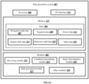
- FIG. 2A shows a detailed block diagram of a path generation system for generating a reference navigation path in real-time for safe navigation of a vehicle in accordance with some embodiments of the present disclosure.
- the path generation system 107 may include data 203 and modules 205.
- the data 203 is stored in a memory 113 configured in the path generation system 107 as shown in the FIG. 2A .
- the data 203 may include navigation path data 207 , segment data 209 , sensor data 211 , angular shift data 213, reference path data 215 and other data 219.
- modules 205 are described herein in detail.
- the segment data 209 may include details of a number of segments in the pre-generated navigation path, the distance of each of the one or more segments and the like.
- the condition determining module 233 may measure the current condition of the vehicle 103 based on one or more parameters.
- the one or more parameters may include, but are not limited to, a load condition of the vehicle 103 , a terrain condition of a terrain, road, or alike where the vehicle 103 is navigating and, a wear and tear condition of the vehicle 103.
- the condition determining module 233 may determine plurality of values corresponding to the one or more parameters using one or more sensors configured in the vehicle 103.
- the path generation module 237 generates a reference navigation path for the selected segment of the pre-generated navigation path based on the angular shift, for safe navigation of the vehicle 103.
- the path generation module 237 may initially identify an intermediate path point among one or more path points in the selected segment. In some embodiments, only one intermediate path point may be selected for each segment. Upon identifying the intermediate path point, the path generation module 237 may identify a new position for the intermediate path point based on the angular shift determined for the selected segment. In some embodiments, the path generation module 237 may identify a new position for the intermediate path point using the below mentioned Equation 2 and Equation 3.
- X 3 X 1 ⁇ 1 / tan ⁇ * Y 1 ⁇ Y 3
- X 3 X 2 ⁇ 1 / tan ⁇ ⁇ * Y 2 ⁇ Y 3
- FIG. 3 shows a flowchart illustrating a method of generating a reference navigation path in real-time for safe navigation of a vehicle in accordance with some embodiments of the present disclosure.
- the method 300 includes receiving, by a processor 109 of the path generation system 107 , a pre-generated navigation path between a source point and a destination point from one or more sources 101.
- the one or more sources 101 may include, but are not limited to, an application related to maps such as a navigation application and a database storing static maps.
- the one or more sources 101 may obtain the pre-generated navigation path using one or more predefined standard techniques such as Dijkstra's algorithm, A-star algorithm and the like, upon receiving the source point and the destination point.
- the method 300 includes, determining, by the processor 109 , an angular shift of the vehicle 103 from the selected segment of the pre-generated navigation path, by comparing the plurality of values corresponding to the current condition of the vehicle 103 with pre-stored values.
- the processor 109 may generate the pre-stored values by conducting a trial run of the vehicle 103 under varying predefined conditions of the vehicle 103.
- condition of the vehicle 103 i.e. the current condition and the predefined condition, may be measured based on one or more parameters.
- the one or more parameters may include, but are not limited to, a load condition of the vehicle 103 , a terrain condition of where the vehicle 103 is navigating and, a wear and tear condition of the vehicle 103.
- the method 300 includes, generating, by the processor 109 , the reference navigation path by identifying a new position for an intermediate path point of the selected segment of the pre-generated navigation path based on the angular shift, for safe navigation of the vehicle 103.
- the processor 109 may identify an intermediate path point among one or more path points in the selected segment. In some embodiments, only one intermediate path point may be selected for each segment. Upon identifying the intermediate path point, the processor 109 may identify a new position for the intermediate path point based on the angular shift determined for the selected segment. Finally, the processor 109 may curve fit co-ordinates of the new position of the intermediate path point to generate the reference navigation path.
- the path generation system 107 may generate the reference navigation path for the one or more segments until the destination point is reached.
- computer system 400 may communicate with input devices 411 and output devices 412.
- the User interface 406 may facilitate display, execution, interaction, manipulation, or operation of program components through textual or graphical facilities.
- user interfaces may provide computer interaction interface elements on a display system operatively connected to the computer system 400 , such as cursors, icons, check boxes, menus, scrollers, windows, widgets, etc.
- Graphical User Interfaces may be employed, including, without limitation, Apple ® Macintosh ® operating systems' Aqua ® , IBM ® OS/2 ® , Microsoft ® Windows ® (e.g., Aero, Metro, etc.), web interface libraries (e.g., ActiveX ® , Java ® , Javascript ® , AJAX, HTML, Adobe ® Flash ® , etc.), or the like.
- the reference navigation path generated based on a current condition of the vehicle in the present disclosure is basically an incorrect path that causes the vehicle to navigate correctly along the pre-generated navigation path due to natural tendency of the vehicle.
Landscapes
- Engineering & Computer Science (AREA)
- Radar, Positioning & Navigation (AREA)
- Remote Sensing (AREA)
- Automation & Control Theory (AREA)
- Physics & Mathematics (AREA)
- General Physics & Mathematics (AREA)
- Aviation & Aerospace Engineering (AREA)
- Transportation (AREA)
- Mechanical Engineering (AREA)
- Human Computer Interaction (AREA)
- Navigation (AREA)
- Business, Economics & Management (AREA)
- Health & Medical Sciences (AREA)
- Artificial Intelligence (AREA)
- Evolutionary Computation (AREA)
- Game Theory and Decision Science (AREA)
- Medical Informatics (AREA)
- Traffic Control Systems (AREA)
Description
- The present subject matter relates generally to field of telematics, and more particularly, but not exclusively to a method and a system for generating a reference navigation path in real-time for safe navigation of a vehicle.
- Generally, vehicles make use of a navigation path for navigating from a source point to a destination point. Nowadays, the navigation path is widely used in autonomous vehicle technology for navigating autonomous vehicles. The autonomous vehicle technology aims to reduce energy consumption, pollution, reduce frequency of crashes and congestion thereby to increase road safety. The autonomous vehicles are the vehicles that are capable of sensing environment around them for moving on the road without any human intervention. The autonomous vehicles sense the environment with help of sensors configured to work in systems such as Light Detection and Ranging (LIDAR) system, Image capturing devices, Global Positioning System (GPS) and the like.
- Existing techniques provide a navigation path for the autonomous vehicles to traverse from the source point to the destination point, along with command velocities such as, linear, and angular velocity to follow a planned navigation path. As an example, few of the existing techniques, generate multiple trajectories of the navigation path based on geography and the sensors attached to the autonomous vehicle. Based on the dynamically occurring obstacles, these techniques may select the best trajectory among the multiple trajectories for navigation of the autonomous vehicle. Further, some existing techniques may generate a navigation path for the autonomous vehicle based on a velocity profile. A few other existing techniques generate a smooth trajectory that maintains uniformity in position, velocity and acceleration of the autonomous vehicle, within constraints of a lane.
- However, the existing techniques fail to solve the problem related to deviation of the autonomous vehicle from the planned navigation path. The deviation may occur when the autonomous vehicle attempts to traverse along the planned navigation path. A few of the existing techniques continuously monitor the autonomous vehicle and adjust steering angle to align the autonomous vehicle with the planned navigation path, when the deviation occurs. However, continuous adjustment of the steering angle throughout the journey results in excessive power drain from the battery of the autonomous vehicle. Also, due to the continuous adjustment, the autonomous vehicle may experience frequent jerks while moving along the navigation path, resulting in an uncomfortable drive.
-
WO 2016/195557 A1 relates to predicting of a risk for rollover of a working machine for load transportation.US 2014/0046530 A1 relates to planning a turn path for a vehicle. - The information disclosed in this background of the disclosure section is only for enhancement of understanding of the general background of the disclosure and should not be taken as an acknowledgement or any form of suggestion that this information forms prior art already known to a person skilled in the art.
- One or more shortcomings of the prior art may be overcome, and additional advantages may be provided through the present disclosure. Additional features and advantages may be realized through the techniques of the present disclosure. Other embodiments and aspects of the disclosure are described in detail herein and are considered a part of the claimed disclosure.
- Disclosed herein is a method of generating by a path generation system associated with a road vehicle, a reference navigation path in real-time for safe navigation of the road vehicle. The method includes receiving, by the path generation system associated with the road vehicle, a pre-generated navigation path between a source point and a destination point, from one or more sources. Upon receiving the pre-generated navigation path, the path generation system identifies, in real-time, a plurality of values corresponding to the current condition of the road vehicle, for a selected segment among one or more segments in the pre-generated navigation path. The road vehicle is configured to navigate along the pre-generated navigation path. Further, the path generation system determines an angular shift of the road vehicle from the selected segment of the pre-generated navigation path, by comparing the plurality of values corresponding to the current condition of the road vehicle with pre-stored values and generates the reference navigation path for the selected segment of the pre-generated navigation path based on the angular shift. Finally, the path generation system provides the reference navigation path to a navigation module associated with the path generation system for safe navigation of the road vehicle, wherein the navigation module causes the road vehicle navigating through the reference navigation path to shift to the pre-generated navigation path to the current condition of the road vehicle.
- Further, the present disclosure includes a path generation system generating a reference navigation path in real-time for safe navigation of a road vehicle. The path generation system includes a processor and a memory communicatively coupled to the processor. The memory stores the processor-executable instructions, which, on execution, causes the processor to receive a pre-generated navigation path between a source point and a destination point, from one or more sources. Upon receiving the pre-generated navigation path, the processor identifies, in real-time, a plurality of values corresponding to a current condition of the road vehicle, for a selected segment among one or more segments in the pre-generated navigation path. The road vehicle is configured to navigate along the pre-generated navigation path. Further, the processor determines an angular shift of the road vehicle from the selected segment of the pre-generated navigation path, by comparing the plurality of values corresponding to the current condition of the road vehicle with pre-stored values and generates the reference navigation path for the selected segment of the pre-generated navigation path based on the angular shift, for safe navigation of the road vehicle. Finally, the processor provides the reference navigation path to a navigation module associated with the path generation system for safe navigation of the road vehicle, wherein the navigation module causes the road vehicle navigating through the reference navigation path to shift to the pre-generated navigation path to the current condition of the road vehicle.
- Further, the present disclosure includes a non-transitory computer readable medium including instructions stored thereon that when processed by at least one processor causes a path generation system to perform operations comprising receiving a pre-generated navigation path between a source point and a destination point, from one or more sources. Upon receiving the pre-generated navigation path, the instructions cause the processor to identify, in real-time, a plurality of values corresponding to a current condition of the road vehicle, for a selected segment among one or more segments in the pre-generated navigation path. The road vehicle is configured to navigate along the pre-generated navigation path. Further, the instructions cause the processor to determine an angular shift of the road vehicle from the selected segment of the pre-generated navigation path, by comparing the plurality of values corresponding to the current condition of the road vehicle with pre-stored values and to generate the reference navigation path for the selected segment of the pre-generated navigation path based on the angular shift, for safe navigation of the road vehicle. Finally, the instructions cause the processor to provide the reference navigation path to a navigation module associated with the path generation system for safe navigation of the road vehicle, wherein the navigation module causes the road vehicle navigating through the reference navigation path to shift to the pre-generated navigation path to the current condition of the road vehicle.
- The foregoing summary is illustrative only and is not intended to be in any way limiting. In addition to the illustrative aspects, embodiments, and features described above, further aspects, embodiments, and features will become apparent by reference to the drawings and the following detailed description.
- The accompanying drawings, which are incorporated in and constitute a part of this disclosure, illustrate exemplary embodiments and, together with the description, serve to explain the disclosed principles. In the figures, the left-most digit(s) of a reference number identifies the figure in which the reference number first appears. The same numbers are used throughout the figures to reference like features and components. Some embodiments of system and/or methods in accordance with embodiments of the present subject matter are now described, by way of example only, and with reference to the accompanying figures, in which:
-
FIG. 1 shows an exemplary architecture for generating a reference navigation path in real-time for safe navigation of a vehicle in accordance with some embodiments of the present disclosure; -
FIG. 2A shows a detailed block diagram of a path generation system for generating a reference navigation path in real-time for safe navigation of a vehicle in accordance with some embodiments of the present disclosure; -
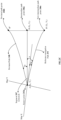
FIG. 2B andFIG. 2C show an exemplary representation of a pre-generated navigation path and a reference navigation path respectively, in accordance with some embodiments of the present disclosure; -
FIG. 3 shows a flowchart illustrating a method of generating a reference navigation path in real-time for safe navigation of a vehicle in accordance with some embodiments of the present disclosure; and -
FIG. 4 is a block diagram of an exemplary computer system for implementing embodiments consistent with the present disclosure. - It should be appreciated by those skilled in the art that any block diagrams herein represent conceptual views of illustrative systems embodying the principles of the present subject matter. Similarly, it will be appreciated that any flow charts, flow diagrams, state transition diagrams, pseudo code, and the like represent various processes which may be substantially represented in computer readable medium and executed by a computer or processor, whether or not such computer or processor is explicitly shown.
- In the present document, the word "exemplary" is used herein to mean "serving as an example, instance, or illustration." Any embodiment or implementation of the present subject matter described herein as "exemplary" is not necessarily to be construed as preferred or advantageous over other embodiments.
- While the disclosure is susceptible to various modifications and alternative forms, specific embodiment thereof has been shown by way of example in the drawings and will be described in detail below.
- The terms "comprises", "comprising", "includes" or any other variations thereof, are intended to cover a non-exclusive inclusion, such that a setup, device or method that includes a list of components or steps does not include only those components or steps but may include other components or steps not expressly listed or inherent to such setup or device or method. In other words, one or more elements in a system or apparatus proceeded by "comprises... a" does not, without more constraints, preclude the existence of other elements or additional elements in the system or method.
- Disclosed herein are a method and a system for generating a reference navigation path in real-time for safe navigation of a vehicle. As an example, the vehicle may be at least one of an autonomous vehicle or a non-autonomous vehicle. A path generation system associated with the vehicle, may receive a pre-generated navigation path between a source point and a destination point from one or more sources. As an example, the one or more sources may include, but are not limited to, an application related to maps such as a navigation application and a database storing static maps. While the vehicle may navigate along the pre-generated navigation path, the path generation system may select a segment among one or more segments in the pre-generated navigation path. In some embodiments, the segment may be generated dynamically. As an example, a part of the pre-generated navigation path which extends up to a distance such as 10 metres, 15 metres and the like, from a current position of the vehicle, may be selected as the segment. Alternatively, in some embodiments, the one or more segments may be pre-generated based on a predefined distance configured in the path generation system.
- Further, the path generation system may identify a plurality of values corresponding to a current condition of the vehicle, for the selected segment. In some embodiments, the plurality of values corresponding to the current condition of the vehicle may be determined using one or more sensors configured in the vehicle. As an example, the one or more sensors may include, but are not limited to, image capturing sensors such as cameras, terrain condition detecting sensors, Global Positioning System (GPS) sensors, occupancy detection sensors, inertial measurement units, load detecting sensors and Light Detection and Ranging (LIDAR).
- In some embodiments, the current condition of the vehicle may be measured based on one or more parameters. As an example, the one or more parameters may include, but are not limited to, a load condition of the vehicle, a terrain condition of where the vehicle is navigating and, a wear and tear condition of the vehicle. In some embodiments, the wear and tear condition may indicate a form of depreciation which is assumed to occur eventually, even when the vehicle is properly maintained. As an example, the wear and tear condition may be measured with respect to broken/corroded parts of the vehicle, alterations made to the vehicle, mechanical/electrical maintenance of the vehicle, overall distance covered by the vehicle and the like. Further, the path generation system may compare the plurality of values corresponding to the current condition of the vehicle with pre-stored values to determine an angular shift of the vehicle from the selected segment of the pre-generated navigation path. In some embodiments, the pre-stored values may be generated by conducting a trial run of the vehicle under varying predefined conditions of the vehicle. In some other embodiments, the path generation system may update the pre-stored values eventually by self-learning. In some embodiments, each of the pre-stored values is associated with one or more pre-recorded angular shift values that are also recorded during the trial run conducted for the vehicle under varying predefined conditions of the vehicle.
- Further, the path generation system may identify an intermediate path point among one or more path points in the selected segment. In some embodiments, only one intermediate path point may be selected for each segment. Upon identifying the intermediate path point, the path generation system may identify a new position for the intermediate path point based on the angular shift determined for the selected segment. Finally, the path generation system may curve fit co-ordinates of the new position of the intermediate path point to generate the reference navigation path. In some embodiments, the path generation system may generate the reference navigation path for the one or more segments until the destination point is reached.
- In some embodiments, the reference navigation path is generated based on the current condition of the vehicle in the present disclosure is basically an incorrect path. The vehicle while navigating in the incorrect path may deviate from the incorrect path due to natural tendency. In some embodiments, the natural tendency is defined as probability of the vehicle to be deviated from a base path at a certain angle, while moving at a certain speed, direction or time, when the vehicle is subjected to a certain condition. As an example, the vehicle may have the natural tendency to deviate towards left direction at an angle of 10 degrees when load of the vehicle exceeds 100kg, instead of moving straight along the pre-generated navigation path. Therefore, the reference navigation path may be generated in accordance with the angular shift such that, when the vehicle navigates along the reference navigation path, due to the natural tendency the vehicle navigates along the pre-generated navigation path, which is the path along which the vehicle is actually intended to navigate.
- Further, the reference navigation path generated in the present disclosure eliminates the need for continuous monitoring and steering angle adjustment to align the vehicle with the pre-generated navigation path, thereby reducing power consumption by the vehicle. Also, the reference navigation path generated in the present disclosure may provide a smooth navigation experience for the vehicle by minimizing jerks experienced by the vehicle.
- A description of an embodiment with several components in communication with each other does not imply that all such components are required. On the contrary a variety of optional components are described to illustrate the wide variety of possible embodiments of the disclosure.
- In the following detailed description of the embodiments of the disclosure, reference is made to the accompanying drawings that form a part hereof, and in which are shown by way of illustration specific embodiments in which the disclosure may be practiced. These embodiments are described in sufficient detail to enable those skilled in the art to practice the disclosure, and it is to be understood that other embodiments may be utilized and that changes may be made without departing from the scope of the present disclosure. The following description is, therefore, not to be taken in a limiting sense.
-
FIG. 1 shows an exemplary architecture for generating a reference navigation path in real-time for safe navigation of a vehicle in accordance with some embodiments of the present disclosure. - The
architecture 100 includes one or more sources,source 1011 to source 101n (collectively referred as one or more sources 101), avehicle 103, apath generation system 107 and anavigation module 114. As an example, the one ormore sources 101 may include, but are not limited to, an application related to maps such as a navigation application and a repository storing static maps. In some embodiments, the one ormore sources 101 may provide static maps generated using Light Detection and Ranging (LIDAR). In some embodiments, the one ormore sources 101 may be associated with thepath generation system 107 via a communication network (not shown inFIG. 1 ). As an example, the communication network may include a wired communication network or a wireless communication network. In some embodiments, thepath generation system 107 may be configured within thevehicle 103 as shown in theFIG. 1 . In some other embodiments, thepath generation system 107 may be remotely associated with thevehicle 103 via the wireless communication network. In some embodiments, thevehicle 103 may be an autonomous vehicle or a non-autonomous vehicle. As an example, thevehicle 103 may be a bike, a car, a truck, a bus and the like. - The
path generation system 107 includes aprocessor 109, an Input/Output (I/O)interface 111 and amemory 113. The I/O interface 111 may be configured to receive a pre-generated navigation path between a source point and a destination point, from the one ormore sources 101. Theprocessor 109 may provide reference navigation path to thenavigation module 114 through the I/O interface 111. In some embodiments, the one ormore sources 101 may obtain the pre-generated navigation path using one or more predefined standard techniques such as Dijkstra's algorithm, A-star algorithm and the like, upon receiving the source point and the destination point. In some embodiments, the source point and the destination point may be provided as inputs to thepath generation system 107 by a user associated with thepath generation system 107. Further, theprocessor 109 may store the pre-generated navigation path in thememory 113 coupled with theprocessor 109. - Upon receiving the pre-generated navigation path, the
processor 109 may select a segment among one or more segments in the pre-generated navigation path, while thevehicle 103 is navigating along the pre-generated navigation path. In some embodiments, theprocessor 109 may generate the segments dynamically. As an example, a part of the pre-generated navigation path which extends up to a distance such as 10 metres, 15 metres and the like, from a current position of thevehicle 103, may be selected as the segment. Alternatively, in some embodiments, theprocessor 109 may pre-generate the one or more segments based on a predefined distance configured in thepath generation system 107. Further, theprocessor 109 may identify a plurality of values corresponding to a current condition of thevehicle 103, for the selected segment. In some embodiments, the plurality of values corresponding to the current condition of thevehicle 103 may be determined using one or more sensors configured in thevehicle 103. As an example, the one or more sensors may include, but are not limited to, image capturing sensors such as cameras, terrain condition detecting sensors, Global Positioning System (GPS) sensors, occupancy detection sensors, inertial measurement units, load detecting sensors and Light Detection and Ranging (LIDAR). - In some embodiments, the
processor 109 may measure the current condition of thevehicle 103 based on one or more parameters. As an example, the one or more parameters may include, but are not limited to, a load condition of thevehicle 103, a terrain condition of where thevehicle 103 is navigating and, a wear and tear condition of thevehicle 103. Further, theprocessor 109 may compare the plurality of values corresponding to the current condition of thevehicle 103 with pre-stored values to determine an angular shift of thevehicle 103 from the selected segment of the pre-generated navigation path. In some embodiments, the pre-stored values may be generated by conducting a trial run of thevehicle 103 under varying predefined conditions of thevehicle 103. In some embodiments, the varying predefined condition of the vehicle may be different combinations of the one or more parameters. As an example, the trial run of thevehicle 103 may be conducted under the predefined condition where the load of thevehicle 103 is 100kg and the terrain condition incudes a slope of 25 degrees. In some embodiments, each of the pre-stored values may be associated with one or more pre-recorded angular shift values. Considering the above mentioned exemplary predefined conditions, an exemplary angular shift value associated with the exemplary predefined condition may be +/- 20 degree. - Further, the
processor 109 may generate a reference navigation path for the selected segment of the pre-generated navigation path based on the angular shift, for safe navigation of thevehicle 103. In some embodiments, theprocessor 109 may generate the reference navigation path for the one or more segments until the destination point is reached. - Upon generating the reference navigation path, the
processor 109 may provide the reference navigation path to thenavigation module 114 associated with thepath generation system 107 for navigating thevehicle 103. In some embodiments, thenavigation module 114 may be configured in thevehicle 103. Thenavigation module 114 may determine a command velocity for thevehicle 103 based on dynamic data received for navigating thevehicle 103 along the reference navigation path. In some embodiments, thevehicle 103 navigating through the reference navigation path may shift to the pre-generated navigation path due to the current condition of thevehicle 103. -
FIG. 2A shows a detailed block diagram of a path generation system for generating a reference navigation path in real-time for safe navigation of a vehicle in accordance with some embodiments of the present disclosure. - In some implementations, the
path generation system 107 may includedata 203 andmodules 205. As an example, thedata 203 is stored in amemory 113 configured in thepath generation system 107 as shown in theFIG. 2A . In one embodiment, thedata 203 may includenavigation path data 207,segment data 209,sensor data 211,angular shift data 213,reference path data 215 andother data 219. In the illustratedFIG. 2A ,modules 205 are described herein in detail. - In some embodiments, the
data 203 may be stored in thememory 113 in form of various data structures. Additionally, thedata 203 can be organized using data models, such as relational or hierarchical data models. Theother data 219 may store data, including temporary data and temporary files, generated by themodules 205 for performing the various functions of thepath generation system 107. - In some embodiments, the
data 203 stored in thememory 113 may be processed by themodules 205 of thepath generation system 107. Themodules 205 may be stored within thememory 113. In an example, themodules 205 communicatively coupled to theprocessor 109 configured in thepath generation system 107, may also be present outside thememory 113 as shown inFIG. 2A and implemented as hardware. As used herein, theterm modules 205 may refer to an application specific integrated circuit (ASIC), an electronic circuit, a processor (shared, dedicated, or group) and memory that execute one or more software or firmware programs, a combinational logic circuit, and/or other suitable components that provide the described functionality. - In some embodiments, the
modules 205 may include, for example, a receivingmodule 231, acondition determining module 233, anangle determination module 235, apath generation module 237 andother modules 239. Theother modules 239 may be used to perform various miscellaneous functionalities of thepath generation system 107. It will be appreciated that suchaforementioned modules 205 may be represented as a single module or a combination of different modules. - In some embodiments, the receiving
module 231 receives a pre-generated navigation path between a source point and a destination point, from one ormore sources 101 when thevehicle 103 is about to start journey from the source point to the destination point. The pre-generated navigation path along with the source point and the destination point may be stored as thenavigation path data 207. As an example, the one ormore sources 101 may include, but are not limited to, an application related to maps such as a navigation application and a repository storing static maps. In some embodiments, the one ormore sources 101 may provide static maps generated using Light Detection and Ranging (LIDAR). - In some embodiments, the
condition determining module 233 identifies a plurality of values corresponding to a current condition of thevehicle 103, for a segment selected among one or more segments. Thecondition determining module 233 may select the segment among the one or more segments in the pre-generated navigation path, while thevehicle 103 is navigating along the pre-generated navigation path. In some embodiments, thecondition determining module 233 may generate the segments dynamically. Alternatively, in some embodiments, thecondition determining module 233 may pre-generate the one or more segments based on a predefined distance configured in thepath generation system 107. The one or more segments may be stored as thesegment data 209. As an example, thesegment data 209 may include details of a number of segments in the pre-generated navigation path, the distance of each of the one or more segments and the like. Thecondition determining module 233 may measure the current condition of thevehicle 103 based on one or more parameters. As an example, the one or more parameters may include, but are not limited to, a load condition of thevehicle 103, a terrain condition of a terrain, road, or alike where thevehicle 103 is navigating and, a wear and tear condition of thevehicle 103. Further, thecondition determining module 233 may determine plurality of values corresponding to the one or more parameters using one or more sensors configured in thevehicle 103. As an example, the one or more sensors may include, but are not limited to, image capturing sensors such as cameras, terrain condition detecting sensors, Global Positioning System (GPS) sensors, occupancy detection sensors, inertial measurement units, load detecting sensors and Light Detection and Ranging (LIDAR). Data received from the one or more sensors may be stored as thesensor data 211. - In some embodiments, the
angle determination module 235 determines an angular shift of thevehicle 103 from the selected segment of the pre-generated navigation path. Theangle determination module 235 may compare the plurality of values corresponding to a current condition of thevehicle 103 with pre-stored values corresponding to predefined conditions of thevehicle 103. In some embodiments, the pre-stored values may be generated by conducting a trial run of thevehicle 103 under varying predefined conditions of thevehicle 103. In some embodiments, each of the pre-stored values is associated with one or more pre-recorded angular shift values. The pre-stored values and the determined angular shift may be stored as theangular shift data 213. Further to the comparison, theangle determination module 235 may select the angular shift value corresponding to each of the one or more parameters, based on the current condition of thevehicle 103. Furthermore, theangle determination module 235 may determine the angular shift of thevehicle 103 using the belowEquation 1.
- In the
above Equation 1, - θ1 indicates angular shift corresponding to the
parameter 1; - θ2 indicates angular shift corresponding to the parameter 2;
- θ3 indicates angular shift corresponding to the parameter 3; and
- θN indicates angular shift corresponding to the parameter N.
- In some embodiments, the
path generation module 237 generates a reference navigation path for the selected segment of the pre-generated navigation path based on the angular shift, for safe navigation of thevehicle 103. In some embodiments, to generate the reference navigation path, thepath generation module 237 may initially identify an intermediate path point among one or more path points in the selected segment. In some embodiments, only one intermediate path point may be selected for each segment. Upon identifying the intermediate path point, thepath generation module 237 may identify a new position for the intermediate path point based on the angular shift determined for the selected segment. In some embodiments, thepath generation module 237 may identify a new position for the intermediate path point using the below mentioned Equation 2 and Equation 3.

- In the above Equation 2,
- X3 and Y3 are co-ordinates of the new position of the intermediate path point;
- X1 and Y1 are co-ordinates of current position of the
vehicle 103; and - Φ is an angle that determines slope with respect to orientation of
vehicle 103. - In the above Equation 3,
- X3 and Y3 are co-ordinates of the new position of the intermediate path point;
- X2 and Y2 are co-ordinates of the intermediate path point of the segment;
- Φ is an angle that determines slope with respect to orientation of
vehicle 103; and - θ is angular shift of the
vehicle 103. - In some embodiments, the
path generation module 237 may generate the co-ordinates for the new position of the intermediate path point by solving Equation 2 and Equation 3. Finally, thepath generation module 237 may curve fit the co-ordinates of the new position of the intermediate path point to generate the reference navigation path for the selected segment. Similarly, thepath generation module 237 may generate the reference navigation path for the one or more segments until the destination point is reached. In some embodiments, the reference navigation path and the new position of the intermediate points may be stored as thereference path data 215. - Upon generating the reference navigation path, the
path generation module 237 provides the reference navigation path to anavigation module 114 associated with thepath generation system 107 for navigating thevehicle 103. In some embodiments, thenavigation module 114 may be configured in thevehicle 103. Thenavigation module 114 may determine a command velocity for thevehicle 103 based on dynamic data received for navigating thevehicle 103 along the reference navigation path. As an example, the dynamic data may include, but is not limited to, data related to one or more obstacles appearing in real-time when thevehicle 103 is navigating along the reference navigation path and data related to terrain associated with the reference navigation path. When thevehicle 103 is navigating along the reference navigation path due to the current condition of thevehicle 103 there may be a shift from the reference navigation path to the pre-generated navigation path, resulting in movement of thevehicle 103 along the pre-generated navigation path as originally intended. - Henceforth, the process of generating a reference navigation path in real-time for safe navigation of a
vehicle 103 is explained with the help of one or more examples for better understanding of the present disclosure. However, the one or more examples should not be considered as limitation of the present disclosure. - Consider an exemplary scenario as shown in the
FIG. 2B , where thevehicle 103 intends to travel from thesource point 243a to thedestination point 243b through thepre-generated navigation path 245. Consider an exemplary intermediate path point 246a for the selectedsegment 247 as shown in theFIG. 2B . Length of the selectedsegment 247 is 10metres as shown in theFIG. 2B . Further, as shown in theFIG. 2B , co-ordinates A (X1, Y1) of thesource point 243a may be (5,2) and co-ordinates of the intermediate path point B (X2, Y2) may be (15,10). - Consider, the current condition of the
vehicle 103 with respect to the one or more parameters is determined to be: - Load condition of the vehicle 103 - 100Kg
- Terrain condition of a road where the
vehicle 103 is navigating:- Slope of the road - 5 degree
- Road curvature - 40 degree
- Further, consider the pre-stored values corresponding to the predefined conditions of the
vehicle 103 are as shown in the below Tables 2, 3 and 4.Table 2 Pre-Condition: Load condition for a Plane road for a straight stretch of 10 meter Load Angular shift 0 +/- 5 degree 50 kg +/- 10 degree 80 kg +/- 12 degree 100 kg +/- 15 degree 120 kg +/- 20 degree 150 kg +/- 25 degree Table 3 Pre-Condition: No load for a straight stretch of 10 meter Slope/10 meter Angular shift 0 degree +/- 0 degree +5 degree +/- 5 degree +10 degree +/- 5 degree + 15 degree +/- 8 degree +20 degree +/- 10 degree +25 degree +/- 12 degree -25 degree +/- 15 degree -20 degree +/- 10 degree -15 degree +/- 8 degree -10 degree +/- 5 degree -5 degree +/- 5 degree Table 4 Pre-Condition: Plane road, No load and a fixed road curvature for 10 metre Fixed Road curvature for 10metre Angular shift +/- 10 degree +/- 5 degree +/- 20 degree +/- 10 degree +/- 30 degree +/- 15 degree +/- 40 degree +/- 20 degree - Upon comparing the current condition of the
vehicle 103 with the pre-stored values, the angular shift value corresponding to the load condition of 100Kg is +/- 15 degree, the angular shift value corresponding to the terrain condition of thevehicle 103 is, with respect to slope of the road, +/- 5 degree and, with respect to road curvature, +/-20 degree. - Therefore, using the
Equation 1, the angular shift is (15 + 5 + 20) = 40 degree, i.e. θ = 40 degree. - Therefore, the
path generation system 107 should compensate the angular shift of 40 degrees for the selectedsegment 247. If the angular shift is not compensated, thevehicle 103 may navigate along a deviatedpath 248 as shown in theFIG. 2C , instead of navigating along thepre-generated navigation path 245. Point B" in theFIG. 2C indicates a deviated path point 246b present on the deviatedpath 248 for theintermediate path point 246a, and to compensate the angular shift, thepath generation system 107 may determine a new position of the intermediate path point 246a using the Equations 2 and 3 for which angle Φ that determines slope with respect to orientation ofvehicle 103 is considered as shown in theFIG. 2C . Consider Φ = 25 degree. Therefore, by substituting the values of θ, Φ, A (X1, Y1) and B (X2, Y2) in Equations 2 and 3, and by further solving the Equations 2 and 3, thepath generation system 107 may determine the new position of theintermediate path point 246a, which is represented by B' (X3, Y3) 246c as shown in theFIG. 2C . Further, thepath generation system 107 curve fits the points A (Xi, Y1) 243a and B' (X3, Y3) 246c to generate areference navigation path 251 for the selectedsegment 247. Similarly, as shown in theFIG. 2B , new positions of intermediate path points C (Xn-1, Yn-1) and D (Xn, Yn) belonging to the n-1th segment 249 and nth segment 250 are also determined to generate the reference navigation path 251 (as shown in theFIG. 2C ) from thesource point 243a to thedestination point 243b. - Therefore, when the
vehicle 103 navigates along thereference navigation path 251, thevehicle 103 compensates the angular shift due to natural tendency that occurs from the current condition of thevehicle 103, because of which thevehicle 103 would navigate correctly on thepre-generated navigation path 245 as intended instead of the deviatedpath 248. -
FIG. 3 shows a flowchart illustrating a method of generating a reference navigation path in real-time for safe navigation of a vehicle in accordance with some embodiments of the present disclosure. - As illustrated in
FIG. 3 , themethod 300 includes one or more blocks illustrating a method of generating a reference navigation path in real-time for safe navigation of avehicle 103. Themethod 300 may be described in the general context of computer executable instructions. Generally, computer executable instructions can include routines, programs, objects, components, data structures, procedures, modules, and functions, which perform functions or implement abstract data types. - The order in which the
method 300 is described is not intended to be construed as a limitation. Additionally, individual blocks may be deleted from the methods without departing from the scope of the subject matter described herein. Furthermore, themethod 300 can be implemented in any suitable hardware, software, firmware, or combination thereof. - At
block 301, themethod 300 includes receiving, by aprocessor 109 of thepath generation system 107, a pre-generated navigation path between a source point and a destination point from one ormore sources 101. As an example, the one ormore sources 101 may include, but are not limited to, an application related to maps such as a navigation application and a database storing static maps. The one ormore sources 101 may obtain the pre-generated navigation path using one or more predefined standard techniques such as Dijkstra's algorithm, A-star algorithm and the like, upon receiving the source point and the destination point. - At
block 303, themethod 300 includes identifying, by theprocessor 109, a plurality of values corresponding to a current condition of thevehicle 103, for a selected segment among one or more segments in the pre-generated navigation path. In some embodiments, thevehicle 103 is configured to navigate along the pre-generated navigation path. - At
block 305, themethod 300 includes, determining, by theprocessor 109, an angular shift of thevehicle 103 from the selected segment of the pre-generated navigation path, by comparing the plurality of values corresponding to the current condition of thevehicle 103 with pre-stored values. In some embodiments, theprocessor 109 may generate the pre-stored values by conducting a trial run of thevehicle 103 under varying predefined conditions of thevehicle 103. In some embodiments, condition of thevehicle 103 i.e. the current condition and the predefined condition, may be measured based on one or more parameters. As an example, the one or more parameters may include, but are not limited to, a load condition of thevehicle 103, a terrain condition of where thevehicle 103 is navigating and, a wear and tear condition of thevehicle 103. - At
block 307, themethod 300 includes, generating, by theprocessor 109, the reference navigation path by identifying a new position for an intermediate path point of the selected segment of the pre-generated navigation path based on the angular shift, for safe navigation of thevehicle 103. In some embodiments, theprocessor 109 may identify an intermediate path point among one or more path points in the selected segment. In some embodiments, only one intermediate path point may be selected for each segment. Upon identifying the intermediate path point, theprocessor 109 may identify a new position for the intermediate path point based on the angular shift determined for the selected segment. Finally, theprocessor 109 may curve fit co-ordinates of the new position of the intermediate path point to generate the reference navigation path. In some embodiments, thepath generation system 107 may generate the reference navigation path for the one or more segments until the destination point is reached. -
FIG. 4 is a block diagram of an exemplary computer system for implementing embodiments consistent with the present disclosure. - In some embodiments,
FIG. 4 illustrates a block diagram of anexemplary computer system 400 for implementing embodiments consistent with the present invention. In some embodiments, thecomputer system 400 can bepath generation system 107 that is used for generating a reference navigation path in real-time for safe navigation of avehicle 103. Thecomputer system 400 may include a central processing unit ("CPU" or "processor") 402. Theprocessor 402 may include at least one data processor for executing program components for executing user or system-generated business processes. A user may include a person, a person using a device such as such as those included in this invention, or such a device itself. Theprocessor 402 may include specialized processing units such as integrated system (bus) controllers, memory management control units, floating point units, graphics processing units, digital signal processing units, etc. - The
processor 402 may be disposed in communication withinput devices 411 andoutput devices 412 via I/O interface 401. The I/O interface 401 may employ communication protocols/methods such as, without limitation, audio, analog, digital, stereo, IEEE-1394, serial bus, Universal Serial Bus (USB), infrared, PS/2, BNC, coaxial, component, composite, Digital Visual Interface (DVI), high-definition multimedia interface (HDMI), Radio Frequency (RF) antennas, S-Video, Video Graphics Array (VGA), IEEE 802.n /b/g/n/x, Bluetooth, cellular (e.g., Code-Division Multiple Access (CDMA), High-Speed Packet Access (HSPA+), Global System For Mobile Communications (GSM), Long-Term Evolution (LTE), WiMax, or the like), etc. - Using the I/
O interface 401,computer system 400 may communicate withinput devices 411 andoutput devices 412. - In some embodiments, the
processor 402 may be disposed in communication with acommunication network 409 via anetwork interface 403. Thenetwork interface 403 may communicate with thecommunication network 409. Thenetwork interface 403 may employ connection protocols including, without limitation, direct connect, Ethernet (e.g., twistedpair 10/100/1000 Base T), Transmission Control Protocol/Internet Protocol (TCP/IP), token ring, IEEE 802.11a/b/g/n/x, etc. Using thenetwork interface 403 and thecommunication network 409, thecomputer system 400 may communicate with one or more sources 410 (410a up to 410n ), and anavigation module 415. Thecommunication network 409 can be implemented as one of the different types of networks, such as intranet or Local Area Network (LAN), Closed Area Network (CAN) and such within the vehicle. Thecommunication network 409 may either be a dedicated network or a shared network, which represents an association of the different types of networks that use a variety of protocols, for example, Hypertext Transfer Protocol (HTTP), CAN Protocol, Transmission Control Protocol/Internet Protocol (TCP/IP), Wireless Application Protocol (WAP), etc., to communicate with each other. Further, thecommunication network 409 may include a variety of network devices, including routers, bridges, servers, computing devices, storage devices, etc. The one or more sources 410 may include, but are not limited to, a navigation application, an application related to maps and a database comprising static maps. In some embodiments, theprocessor 402 may be disposed in communication with a memory 405 (e.g., RAM, ROM, etc. not shown inFIG. 4 ) via astorage interface 404. Thestorage interface 404 may connect tomemory 405 including, without limitation, memory drives, removable disc drives, etc., employing connection protocols such as Serial Advanced Technology Attachment (SATA), Integrated Drive Electronics (IDE), IEEE-1394, Universal Serial Bus (USB), fibre channel, Small Computer Systems Interface (SCSI), etc. The memory drives may further include a drum, magnetic disc drive, magneto-optical drive, optical drive, Redundant Array of Independent Discs (RAID), solid-state memory devices, solid-state drives, etc. - The
memory 405 may store a collection of program or database components, including, without limitation, a user interface 406, anoperating system 407, aweb browser 408 etc. In some embodiments, thecomputer system 400 may store user/application data, such as the data, variables, records, etc. as described in this invention. Such databases may be implemented as fault-tolerant, relational, scalable, secure databases such as Oracle or Sybase. - The
operating system 407 may facilitate resource management and operation of thecomputer system 400. Examples of operating systems include, without limitation, APPLE® MACINTOSH® OS X®, UNIX®, UNIX-like system distributions (E.G., BERKELEY SOFTWARE DISTRIBUTION® (BSD), FREEBSD®, NETBSD®, OPENBSD, etc.), LINUX® DISTRIBUTIONS (E.G., RED HAT®, UBUNTU®, KUBUNTU®, etc.), IBM®OS/2®, MICROSOFT® WINDOWS® (XP®, VISTA®/7/8, 10 etc.), APPLE® IOS®, GOOGLE™ ANDROID™, BLACKBERRY® OS, or the like. The User interface 406 may facilitate display, execution, interaction, manipulation, or operation of program components through textual or graphical facilities. For example, user interfaces may provide computer interaction interface elements on a display system operatively connected to thecomputer system 400, such as cursors, icons, check boxes, menus, scrollers, windows, widgets, etc. Graphical User Interfaces (GUIs) may be employed, including, without limitation, Apple® Macintosh® operating systems' Aqua®, IBM® OS/2®, Microsoft® Windows® (e.g., Aero, Metro, etc.), web interface libraries (e.g., ActiveX®, Java®, Javascript®, AJAX, HTML, Adobe® Flash®, etc.), or the like. - In some embodiments, the
computer system 400 may implement theweb browser 408 stored program components. Theweb browser 408 may be a hypertext viewing application, such as MICROSOFT® INTERNET EXPLORER®, GOOGLE™ CHROME™, MOZILLA® FIREFOX®, APPLE® SAFARI®, etc. Secure web browsing may be provided using Secure Hypertext Transport Protocol (HTTPS), Secure Sockets Layer (SSL), Transport Layer Security (TLS), etc.Web browsers 408 may utilize facilities such as AJAX, DHTML, ADOBE® FLASH®, JAVASCRIPT®, JAVA®, Application Programming Interfaces (APIs), etc. In some embodiments, thecomputer system 400 may implement a mail server stored program component. The mail server may be an Internet mail server such as Microsoft Exchange, or the like. The mail server may utilize facilities such as Active Server Pages (ASP), ACTIVEX®, ANSI® C++/C#, MICROSOFT®, .NET, CGI SCRIPTS, JAVA®, JAVASCRIPT®, PERL®, PHP, PYTHON®, WEBOBJECTS®, etc. The mail server may utilize communication protocols such as Internet Message Access Protocol (IMAP), Messaging Application Programming Interface (MAPI), MICROSOFT® exchange, Post Office Protocol (POP), Simple Mail Transfer Protocol (SMTP), or the like. In some embodiments, thecomputer system 400 may implement a mail client stored program component. The mail client may be a mail viewing application, such as APPLE® MAIL, MICROSOFT® ENTOURAGE®, MICROSOFT® OUTLOOK®, MOZILLA® THUNDERBIRD®, etc. - Furthermore, one or more computer-readable storage media may be utilized in implementing embodiments consistent with the present invention. A computer-readable storage medium refers to any type of physical memory on which information or data readable by a processor may be stored. Thus, a computer-readable storage medium may store instructions for execution by one or more processors, including instructions for causing the processor(s) to perform steps or stages consistent with the embodiments described herein. The term "computer-readable medium" should be understood to include tangible items and exclude carrier waves and transient signals, i.e., non-transitory. Examples include Random Access Memory (RAM), Read-Only Memory (ROM), volatile memory, non-volatile memory, hard drives, Compact Disc (CD) ROMs, Digital Video Disc (DVDs), flash drives, disks, and any other known physical storage media.
- Advantages of the present disclosure are set out in the following paragraphs.
- The present disclosure provides a method and a system for generating a reference navigation path in real-time for safe navigation of a vehicle.
- The reference navigation path generated based on a current condition of the vehicle in the present disclosure is basically an incorrect path that causes the vehicle to navigate correctly along the pre-generated navigation path due to natural tendency of the vehicle.
- The reference navigation path generated in the present disclosure eliminates the need for continuous monitoring and steering angle adjustment to align the vehicle with the pre-generated navigation path, thereby reducing power consumption by the vehicle.
- The reference navigation path is generated in the present disclosure by considering vehicle profile data. Therefore, the reference navigation path provides a smooth and safe navigation experience for the vehicle by minimizing jerks experienced by the vehicle.
- The present disclosure eliminates need for continuous monitoring and steering angle adjustment to align the vehicle with the pre-generated navigation path, thereby reducing power consumption by the vehicle and also minimizing jerks experienced by the vehicle.
- A description of an embodiment with several components in communication with each other does not imply that all such components are required. On the contrary a variety of optional components are described to illustrate the wide variety of possible embodiments of the invention. When a single device or article is described herein, it will be apparent that more than one device/article (whether or not they cooperate) may be used in place of a single device/article. Similarly, where more than one device or article is described herein (whether or not they cooperate), it will be apparent that a single device/article may be used in place of the more than one device or article or a different number of devices/articles may be used instead of the shown number of devices or programs. The functionality and/or the features of a device may be alternatively embodied by one or more other devices which are not explicitly described as having such functionality/features. Thus, other embodiments of the invention need not include the device itself.
- The specification has described a method and a system for generating a reference navigation path in real-time for safe navigation of a vehicle. These examples are presented herein for purposes of illustration, and not limitation.
- Finally, the language used in the specification has been principally selected for readability and instructional purposes, and it may not have been selected to delineate or circumscribe the inventive subject matter. It is therefore intended that the scope of the invention be limited not by this detailed description, but rather by any claims that issue on an application based here on. Accordingly, the embodiments of the present invention are intended to be illustrative, but not limiting, of the scope of the invention, which is set forth in the following claims.
Claims (10)
- A computer-implemented method of generating, by a path generation system (107) associated with a road vehicle (103), a reference navigation path in real-time for safe navigation of the road vehicle (103), the method comprising:receiving a pre-generated navigation path between a source point and a destination point, from one or more sources (101);identifying, in real-time, a plurality of values corresponding to a current condition of the road vehicle (103), for a selected segment among one or more segments in the pre-generated navigation path, wherein the road vehicle (103) is configured to navigate along the pre-generated navigation path;determining an angular shift of the road vehicle (103) from the selected segment of the pre-generated navigation path, by comparing the plurality of values corresponding to the current condition of the road vehicle (103) with pre-stored values;generating the reference navigation path for the selected segment of the pre-generated navigation path based on the angular shift; characterized in that the method further comprises:
providing the reference navigation path to a navigation module associated with the path generation system (107) for safe navigation of the road vehicle (103), wherein the navigation module causes the road vehicle (103) navigating through the reference navigation path to shift to the pre-generated navigation path due to the current condition of the road vehicle (103). - The method as claimed in claim 1, wherein the pre-stored values are generated by a processor (109) conducting a trial run of the road vehicle (103) under varying predefined conditions of the road vehicle (103).
- The method as claimed in claim 2, wherein the pre-stored values corresponding to the predefined conditions of the road vehicle (103) are associated with one or more pre-recorded angular shift values recorded during the trial run conducted for the road vehicle (103) under varying predefined conditions of the road vehicle (103).
- The method as claimed in claim 2 or claim 3, wherein the current condition of the road vehicle (103) is measured based on one or more parameters comprising at least one of a load condition of the road vehicle (103), a terrain condition of where the road vehicle (103) is navigating, and a wear and tear condition of the road vehicle (103).
- The method as claimed in any of the preceding claims, wherein the plurality of values corresponding to the current condition of the road vehicle (103) is determined using one or more sensors configured in the road vehicle (103).
- The method as claimed in any of the preceding claims, wherein generating the reference navigation path comprises:identifying an intermediate path point among one or more path points in the selected segment; andidentifying a new position for the intermediate path point based on the angular shift, wherein co-ordinates of the new position of the intermediate path point (246c) and the source point (243a) are curve fitted to generate the reference navigation path.
- The method as claimed in any of the preceding claims, further comprising generating the reference navigation path for the one or more segments until the destination point is reached.
- A path generation system (107) for generating a reference navigation path in real-time for safe navigation of a road vehicle (103), system comprising:a processor (109); anda memory (113) communicatively coupled to the processor (109), wherein the memory (113) stores the processor-executable instructions, which, on execution, causes the path generation system to perform the method as claimed in any of the preceding claims.
- A computer readable medium including instructions stored thereon that when processed by at least one processor (109) causes a path generation system (107) to perform the method as claimed in any of claims 1 to 7.
- A computer program product comprising instructions that, when executed by a computer, cause the computer to perform the method of any of claims 1 to 7.
Applications Claiming Priority (1)
| Application Number | Priority Date | Filing Date | Title |
|---|---|---|---|
| IN201841005816 | 2018-02-15 |
Publications (2)
| Publication Number | Publication Date |
|---|---|
| EP3527946A1 EP3527946A1 (en) | 2019-08-21 |
| EP3527946B1 true EP3527946B1 (en) | 2024-07-03 |
Family
ID=61837674
Family Applications (1)
| Application Number | Title | Priority Date | Filing Date |
|---|---|---|---|
| EP18164925.2A Active EP3527946B1 (en) | 2018-02-15 | 2018-03-29 | Method and system for real-time generation of reference navigation path for navigation of vehicle |
Country Status (2)
| Country | Link |
|---|---|
| US (1) | US10585436B2 (en) |
| EP (1) | EP3527946B1 (en) |
Families Citing this family (9)
| Publication number | Priority date | Publication date | Assignee | Title |
|---|---|---|---|---|
| US10788831B2 (en) * | 2017-10-06 | 2020-09-29 | Wipro Limited | Method and device for identifying center of a path for navigation of autonomous vehicles |
| US10585436B2 (en) * | 2018-02-15 | 2020-03-10 | Wipro Limited | Method and system for real-time generation of reference navigation path for navigation of vehicle |
| US11392127B2 (en) * | 2018-10-15 | 2022-07-19 | Zoox, Inc. | Trajectory initialization |
| JP7011015B1 (en) * | 2020-09-30 | 2022-01-26 | 日立建機株式会社 | Transport vehicle control system |
| CN112541457B (en) * | 2020-12-21 | 2021-10-26 | 重庆紫光华山智安科技有限公司 | Searching method and related device for monitoring node |
| US11747156B2 (en) * | 2021-01-14 | 2023-09-05 | Wipro Limited | Method and system for generating maneuvering trajectories for a vehicle |
| CN113093743B (en) * | 2021-03-30 | 2022-08-30 | 西北农林科技大学 | Navigation control method based on virtual radar model and deep neural network |
| CN114114930B (en) * | 2022-01-28 | 2022-04-19 | 清华大学 | Method, device, device and medium for generating local reference path for automobiles |
| CN114559946B (en) * | 2022-03-31 | 2025-03-07 | 北京主线科技有限公司 | A reference line determination method, device, equipment and medium |
Citations (1)
| Publication number | Priority date | Publication date | Assignee | Title |
|---|---|---|---|---|
| US20150185734A1 (en) * | 2012-07-12 | 2015-07-02 | Renault S.A.S. | Method for controlling the path of an autonomous vehicle having steered wheels |
Family Cites Families (10)
| Publication number | Priority date | Publication date | Assignee | Title |
|---|---|---|---|---|
| EP0405623A3 (en) | 1986-05-21 | 1991-02-06 | Kabushiki Kaisha Komatsu Seisakusho | System for inspecting a dust proofing property |
| EP2280241A3 (en) * | 2009-07-30 | 2017-08-23 | QinetiQ Limited | Vehicle control |
| US9098086B2 (en) * | 2012-08-07 | 2015-08-04 | Caterpillar Inc. | Method and system for planning a turn path for a machine |
| US10060370B2 (en) * | 2014-10-02 | 2018-08-28 | Ford Global Technologies, Llc | Adaptive model predictive control for vehicle route planning |
| KR101664582B1 (en) * | 2014-11-12 | 2016-10-10 | 현대자동차주식회사 | Path Planning Apparatus and Method for Autonomous Vehicle |
| WO2016195557A1 (en) | 2015-06-03 | 2016-12-08 | Volvo Construction Equipment Ab | A method and system for predicting a risk for rollover of a working machine |
| US9910441B2 (en) * | 2015-11-04 | 2018-03-06 | Zoox, Inc. | Adaptive autonomous vehicle planner logic |
| US10503171B2 (en) * | 2017-08-17 | 2019-12-10 | Wipro Limited | Method and system for determining drivable navigation path for an autonomous vehicle |
| US10768011B2 (en) * | 2017-08-31 | 2020-09-08 | Wipro Limited | Method and system for positioning an autonomous vehicle on a navigation map |
| US10585436B2 (en) * | 2018-02-15 | 2020-03-10 | Wipro Limited | Method and system for real-time generation of reference navigation path for navigation of vehicle |
-
2018
- 2018-03-29 US US15/939,759 patent/US10585436B2/en active Active
- 2018-03-29 EP EP18164925.2A patent/EP3527946B1/en active Active
Patent Citations (1)
| Publication number | Priority date | Publication date | Assignee | Title |
|---|---|---|---|---|
| US20150185734A1 (en) * | 2012-07-12 | 2015-07-02 | Renault S.A.S. | Method for controlling the path of an autonomous vehicle having steered wheels |
Also Published As
| Publication number | Publication date |
|---|---|
| EP3527946A1 (en) | 2019-08-21 |
| US10585436B2 (en) | 2020-03-10 |
| US20190250624A1 (en) | 2019-08-15 |
Similar Documents
| Publication | Publication Date | Title |
|---|---|---|
| EP3527946B1 (en) | Method and system for real-time generation of reference navigation path for navigation of vehicle | |
| EP3575911B1 (en) | Method and system for correcting velocity of autonomous vehicle to navigate along planned navigation path | |
| US10684131B2 (en) | Method and system for generating and updating vehicle navigation maps with features of navigation paths | |
| US10837789B2 (en) | Method and system for determining an optimal path for navigation of a vehicle | |
| US10503171B2 (en) | Method and system for determining drivable navigation path for an autonomous vehicle | |
| EP3376327B1 (en) | Method of controlling an autonomous vehicle and a collision avoidance device thereof | |
| EP3846147A1 (en) | A method and system for reducing road congestion | |
| US10324473B2 (en) | Method and system for generating a safe navigation path for navigating a driverless vehicle | |
| US11181919B2 (en) | Method and system for determining an optimal trajectory for navigation of an autonomous vehicle | |
| EP3527947B1 (en) | Method for generating a safe navigation path for a vehicle and a system thereof | |
| EP3547061B1 (en) | Method and system for generating a safe navigation path in real-time for navigating a vehicle | |
| US20210096568A1 (en) | System and method for dynamically adjusting a trajectory of an autonomous vehicle during real-time navigation | |
| EP3505870B1 (en) | Method and system for generating a safe navigation path for a vehicle | |
| US10449959B2 (en) | System and method for navigating an autonomous vehicle | |
| US11300960B2 (en) | Method and device for navigating an autonomous vehicle | |
| US11442467B2 (en) | Method and system for generating a trajectory for navigating an autonomous vehicle | |
| US11049339B2 (en) | Method and system for validating odometer performance in an autonomous vehicle in real-time | |
| US12472988B2 (en) | Method and system for predicting gesture of subjects surrounding an autonomous vehicle | |
| US11639184B2 (en) | Method and system for diagnosing autonomous vehicles | |
| US12539862B2 (en) | Method and system for lane tracking for an autonomous vehicle |
Legal Events
| Date | Code | Title | Description |
|---|---|---|---|
| PUAI | Public reference made under article 153(3) epc to a published international application that has entered the european phase |
Free format text: ORIGINAL CODE: 0009012 |
|
| STAA | Information on the status of an ep patent application or granted ep patent |
Free format text: STATUS: THE APPLICATION HAS BEEN PUBLISHED |
|
| AK | Designated contracting states |
Kind code of ref document: A1 Designated state(s): AL AT BE BG CH CY CZ DE DK EE ES FI FR GB GR HR HU IE IS IT LI LT LU LV MC MK MT NL NO PL PT RO RS SE SI SK SM TR |
|
| AX | Request for extension of the european patent |
Extension state: BA ME |
|
| STAA | Information on the status of an ep patent application or granted ep patent |
Free format text: STATUS: REQUEST FOR EXAMINATION WAS MADE |
|
| 17P | Request for examination filed |
Effective date: 20200220 |
|
| RBV | Designated contracting states (corrected) |
Designated state(s): AL AT BE BG CH CY CZ DE DK EE ES FI FR GB GR HR HU IE IS IT LI LT LU LV MC MK MT NL NO PL PT RO RS SE SI SK SM TR |
|
| STAA | Information on the status of an ep patent application or granted ep patent |
Free format text: STATUS: EXAMINATION IS IN PROGRESS |
|
| 17Q | First examination report despatched |
Effective date: 20220928 |
|
| GRAP | Despatch of communication of intention to grant a patent |
Free format text: ORIGINAL CODE: EPIDOSNIGR1 |
|
| STAA | Information on the status of an ep patent application or granted ep patent |
Free format text: STATUS: GRANT OF PATENT IS INTENDED |
|
| RIC1 | Information provided on ipc code assigned before grant |
Ipc: G05D 1/00 20060101ALI20240125BHEP Ipc: G01C 21/26 20060101AFI20240125BHEP |
|
| INTG | Intention to grant announced |
Effective date: 20240208 |
|
| RIN1 | Information on inventor provided before grant (corrected) |
Inventor name: SARKAR, MANAS Inventor name: KUMAR, BALAJI SUNIL |
|
| GRAS | Grant fee paid |
Free format text: ORIGINAL CODE: EPIDOSNIGR3 |
|
| GRAA | (expected) grant |
Free format text: ORIGINAL CODE: 0009210 |
|
| STAA | Information on the status of an ep patent application or granted ep patent |
Free format text: STATUS: THE PATENT HAS BEEN GRANTED |
|
| AK | Designated contracting states |
Kind code of ref document: B1 Designated state(s): AL AT BE BG CH CY CZ DE DK EE ES FI FR GB GR HR HU IE IS IT LI LT LU LV MC MK MT NL NO PL PT RO RS SE SI SK SM TR |
|
| REG | Reference to a national code |
Ref country code: CH Ref legal event code: EP |
|
| REG | Reference to a national code |
Ref country code: DE Ref legal event code: R096 Ref document number: 602018071204 Country of ref document: DE |
|
| P01 | Opt-out of the competence of the unified patent court (upc) registered |
Free format text: CASE NUMBER: APP_39270/2024 Effective date: 20240702 |
|
| REG | Reference to a national code |
Ref country code: LT Ref legal event code: MG9D |
|
| REG | Reference to a national code |
Ref country code: NL Ref legal event code: MP Effective date: 20240703 |
|
| PG25 | Lapsed in a contracting state [announced via postgrant information from national office to epo] |
Ref country code: PT Free format text: LAPSE BECAUSE OF FAILURE TO SUBMIT A TRANSLATION OF THE DESCRIPTION OR TO PAY THE FEE WITHIN THE PRESCRIBED TIME-LIMIT Effective date: 20241104 |
|
| REG | Reference to a national code |
Ref country code: AT Ref legal event code: MK05 Ref document number: 1700232 Country of ref document: AT Kind code of ref document: T Effective date: 20240703 |
|
| PG25 | Lapsed in a contracting state [announced via postgrant information from national office to epo] |
Ref country code: NL Free format text: LAPSE BECAUSE OF FAILURE TO SUBMIT A TRANSLATION OF THE DESCRIPTION OR TO PAY THE FEE WITHIN THE PRESCRIBED TIME-LIMIT Effective date: 20240703 |
|
| PG25 | Lapsed in a contracting state [announced via postgrant information from national office to epo] |
Ref country code: PT Free format text: LAPSE BECAUSE OF FAILURE TO SUBMIT A TRANSLATION OF THE DESCRIPTION OR TO PAY THE FEE WITHIN THE PRESCRIBED TIME-LIMIT Effective date: 20241104 Ref country code: NL Free format text: LAPSE BECAUSE OF FAILURE TO SUBMIT A TRANSLATION OF THE DESCRIPTION OR TO PAY THE FEE WITHIN THE PRESCRIBED TIME-LIMIT Effective date: 20240703 |
|
| PG25 | Lapsed in a contracting state [announced via postgrant information from national office to epo] |
Ref country code: NO Free format text: LAPSE BECAUSE OF FAILURE TO SUBMIT A TRANSLATION OF THE DESCRIPTION OR TO PAY THE FEE WITHIN THE PRESCRIBED TIME-LIMIT Effective date: 20241003 |
|
| PG25 | Lapsed in a contracting state [announced via postgrant information from national office to epo] |
Ref country code: GR Free format text: LAPSE BECAUSE OF FAILURE TO SUBMIT A TRANSLATION OF THE DESCRIPTION OR TO PAY THE FEE WITHIN THE PRESCRIBED TIME-LIMIT Effective date: 20241004 Ref country code: FI Free format text: LAPSE BECAUSE OF FAILURE TO SUBMIT A TRANSLATION OF THE DESCRIPTION OR TO PAY THE FEE WITHIN THE PRESCRIBED TIME-LIMIT Effective date: 20240703 Ref country code: PL Free format text: LAPSE BECAUSE OF FAILURE TO SUBMIT A TRANSLATION OF THE DESCRIPTION OR TO PAY THE FEE WITHIN THE PRESCRIBED TIME-LIMIT Effective date: 20240703 |
|
| PG25 | Lapsed in a contracting state [announced via postgrant information from national office to epo] |
Ref country code: BG Free format text: LAPSE BECAUSE OF FAILURE TO SUBMIT A TRANSLATION OF THE DESCRIPTION OR TO PAY THE FEE WITHIN THE PRESCRIBED TIME-LIMIT Effective date: 20240703 |
|
| PG25 | Lapsed in a contracting state [announced via postgrant information from national office to epo] |
Ref country code: LV Free format text: LAPSE BECAUSE OF FAILURE TO SUBMIT A TRANSLATION OF THE DESCRIPTION OR TO PAY THE FEE WITHIN THE PRESCRIBED TIME-LIMIT Effective date: 20240703 |
|
| PG25 | Lapsed in a contracting state [announced via postgrant information from national office to epo] |
Ref country code: IS Free format text: LAPSE BECAUSE OF FAILURE TO SUBMIT A TRANSLATION OF THE DESCRIPTION OR TO PAY THE FEE WITHIN THE PRESCRIBED TIME-LIMIT Effective date: 20241103 Ref country code: AT Free format text: LAPSE BECAUSE OF FAILURE TO SUBMIT A TRANSLATION OF THE DESCRIPTION OR TO PAY THE FEE WITHIN THE PRESCRIBED TIME-LIMIT Effective date: 20240703 |
|
| PG25 | Lapsed in a contracting state [announced via postgrant information from national office to epo] |
Ref country code: CZ Free format text: LAPSE BECAUSE OF FAILURE TO SUBMIT A TRANSLATION OF THE DESCRIPTION OR TO PAY THE FEE WITHIN THE PRESCRIBED TIME-LIMIT Effective date: 20240703 Ref country code: HR Free format text: LAPSE BECAUSE OF FAILURE TO SUBMIT A TRANSLATION OF THE DESCRIPTION OR TO PAY THE FEE WITHIN THE PRESCRIBED TIME-LIMIT Effective date: 20240703 |
|
| PG25 | Lapsed in a contracting state [announced via postgrant information from national office to epo] |
Ref country code: RS Free format text: LAPSE BECAUSE OF FAILURE TO SUBMIT A TRANSLATION OF THE DESCRIPTION OR TO PAY THE FEE WITHIN THE PRESCRIBED TIME-LIMIT Effective date: 20241003 Ref country code: ES Free format text: LAPSE BECAUSE OF FAILURE TO SUBMIT A TRANSLATION OF THE DESCRIPTION OR TO PAY THE FEE WITHIN THE PRESCRIBED TIME-LIMIT Effective date: 20240703 |
|
| PG25 | Lapsed in a contracting state [announced via postgrant information from national office to epo] |
Ref country code: RS Free format text: LAPSE BECAUSE OF FAILURE TO SUBMIT A TRANSLATION OF THE DESCRIPTION OR TO PAY THE FEE WITHIN THE PRESCRIBED TIME-LIMIT Effective date: 20241003 Ref country code: PL Free format text: LAPSE BECAUSE OF FAILURE TO SUBMIT A TRANSLATION OF THE DESCRIPTION OR TO PAY THE FEE WITHIN THE PRESCRIBED TIME-LIMIT Effective date: 20240703 Ref country code: NO Free format text: LAPSE BECAUSE OF FAILURE TO SUBMIT A TRANSLATION OF THE DESCRIPTION OR TO PAY THE FEE WITHIN THE PRESCRIBED TIME-LIMIT Effective date: 20241003 Ref country code: LV Free format text: LAPSE BECAUSE OF FAILURE TO SUBMIT A TRANSLATION OF THE DESCRIPTION OR TO PAY THE FEE WITHIN THE PRESCRIBED TIME-LIMIT Effective date: 20240703 Ref country code: IS Free format text: LAPSE BECAUSE OF FAILURE TO SUBMIT A TRANSLATION OF THE DESCRIPTION OR TO PAY THE FEE WITHIN THE PRESCRIBED TIME-LIMIT Effective date: 20241103 Ref country code: HR Free format text: LAPSE BECAUSE OF FAILURE TO SUBMIT A TRANSLATION OF THE DESCRIPTION OR TO PAY THE FEE WITHIN THE PRESCRIBED TIME-LIMIT Effective date: 20240703 Ref country code: GR Free format text: LAPSE BECAUSE OF FAILURE TO SUBMIT A TRANSLATION OF THE DESCRIPTION OR TO PAY THE FEE WITHIN THE PRESCRIBED TIME-LIMIT Effective date: 20241004 Ref country code: FI Free format text: LAPSE BECAUSE OF FAILURE TO SUBMIT A TRANSLATION OF THE DESCRIPTION OR TO PAY THE FEE WITHIN THE PRESCRIBED TIME-LIMIT Effective date: 20240703 Ref country code: ES Free format text: LAPSE BECAUSE OF FAILURE TO SUBMIT A TRANSLATION OF THE DESCRIPTION OR TO PAY THE FEE WITHIN THE PRESCRIBED TIME-LIMIT Effective date: 20240703 Ref country code: CZ Free format text: LAPSE BECAUSE OF FAILURE TO SUBMIT A TRANSLATION OF THE DESCRIPTION OR TO PAY THE FEE WITHIN THE PRESCRIBED TIME-LIMIT Effective date: 20240703 Ref country code: BG Free format text: LAPSE BECAUSE OF FAILURE TO SUBMIT A TRANSLATION OF THE DESCRIPTION OR TO PAY THE FEE WITHIN THE PRESCRIBED TIME-LIMIT Effective date: 20240703 Ref country code: AT Free format text: LAPSE BECAUSE OF FAILURE TO SUBMIT A TRANSLATION OF THE DESCRIPTION OR TO PAY THE FEE WITHIN THE PRESCRIBED TIME-LIMIT Effective date: 20240703 |
|
| REG | Reference to a national code |
Ref country code: DE Ref legal event code: R097 Ref document number: 602018071204 Country of ref document: DE |
|
| PG25 | Lapsed in a contracting state [announced via postgrant information from national office to epo] |
Ref country code: RO Free format text: LAPSE BECAUSE OF FAILURE TO SUBMIT A TRANSLATION OF THE DESCRIPTION OR TO PAY THE FEE WITHIN THE PRESCRIBED TIME-LIMIT Effective date: 20240703 Ref country code: SM Free format text: LAPSE BECAUSE OF FAILURE TO SUBMIT A TRANSLATION OF THE DESCRIPTION OR TO PAY THE FEE WITHIN THE PRESCRIBED TIME-LIMIT Effective date: 20240703 Ref country code: DK Free format text: LAPSE BECAUSE OF FAILURE TO SUBMIT A TRANSLATION OF THE DESCRIPTION OR TO PAY THE FEE WITHIN THE PRESCRIBED TIME-LIMIT Effective date: 20240703 |
|
| PG25 | Lapsed in a contracting state [announced via postgrant information from national office to epo] |
Ref country code: EE Free format text: LAPSE BECAUSE OF FAILURE TO SUBMIT A TRANSLATION OF THE DESCRIPTION OR TO PAY THE FEE WITHIN THE PRESCRIBED TIME-LIMIT Effective date: 20240703 |
|
| PG25 | Lapsed in a contracting state [announced via postgrant information from national office to epo] |
Ref country code: IT Free format text: LAPSE BECAUSE OF FAILURE TO SUBMIT A TRANSLATION OF THE DESCRIPTION OR TO PAY THE FEE WITHIN THE PRESCRIBED TIME-LIMIT Effective date: 20240703 Ref country code: SK Free format text: LAPSE BECAUSE OF FAILURE TO SUBMIT A TRANSLATION OF THE DESCRIPTION OR TO PAY THE FEE WITHIN THE PRESCRIBED TIME-LIMIT Effective date: 20240703 |
|
| PLBE | No opposition filed within time limit |
Free format text: ORIGINAL CODE: 0009261 |
|
| STAA | Information on the status of an ep patent application or granted ep patent |
Free format text: STATUS: NO OPPOSITION FILED WITHIN TIME LIMIT |
|
| 26N | No opposition filed |
Effective date: 20250404 |
|
| PG25 | Lapsed in a contracting state [announced via postgrant information from national office to epo] |
Ref country code: SE Free format text: LAPSE BECAUSE OF FAILURE TO SUBMIT A TRANSLATION OF THE DESCRIPTION OR TO PAY THE FEE WITHIN THE PRESCRIBED TIME-LIMIT Effective date: 20240703 |
|
| PG25 | Lapsed in a contracting state [announced via postgrant information from national office to epo] |
Ref country code: MC Free format text: LAPSE BECAUSE OF FAILURE TO SUBMIT A TRANSLATION OF THE DESCRIPTION OR TO PAY THE FEE WITHIN THE PRESCRIBED TIME-LIMIT Effective date: 20240703 |
|
| REG | Reference to a national code |
Ref country code: CH Ref legal event code: H13 Free format text: ST27 STATUS EVENT CODE: U-0-0-H10-H13 (AS PROVIDED BY THE NATIONAL OFFICE) Effective date: 20251023 |
|
| PG25 | Lapsed in a contracting state [announced via postgrant information from national office to epo] |
Ref country code: LU Free format text: LAPSE BECAUSE OF NON-PAYMENT OF DUE FEES Effective date: 20250329 |
|
| REG | Reference to a national code |
Ref country code: BE Ref legal event code: MM Effective date: 20250331 |
|
| PG25 | Lapsed in a contracting state [announced via postgrant information from national office to epo] |
Ref country code: BE Free format text: LAPSE BECAUSE OF NON-PAYMENT OF DUE FEES Effective date: 20250331 |
|
| PG25 | Lapsed in a contracting state [announced via postgrant information from national office to epo] |
Ref country code: CH Free format text: LAPSE BECAUSE OF NON-PAYMENT OF DUE FEES Effective date: 20250331 |
|
| PG25 | Lapsed in a contracting state [announced via postgrant information from national office to epo] |
Ref country code: IE Free format text: LAPSE BECAUSE OF NON-PAYMENT OF DUE FEES Effective date: 20250329 |
|
| PGFP | Annual fee paid to national office [announced via postgrant information from national office to epo] |
Ref country code: GB Payment date: 20260209 Year of fee payment: 9 |
|
| PGFP | Annual fee paid to national office [announced via postgrant information from national office to epo] |
Ref country code: DE Payment date: 20260204 Year of fee payment: 9 |
|
| PGFP | Annual fee paid to national office [announced via postgrant information from national office to epo] |
Ref country code: FR Payment date: 20260209 Year of fee payment: 9 |