EP3527929A1 - High explosive firing mechanism - Google Patents
High explosive firing mechanism Download PDFInfo
- Publication number
- EP3527929A1 EP3527929A1 EP18213155.7A EP18213155A EP3527929A1 EP 3527929 A1 EP3527929 A1 EP 3527929A1 EP 18213155 A EP18213155 A EP 18213155A EP 3527929 A1 EP3527929 A1 EP 3527929A1
- Authority
- EP
- European Patent Office
- Prior art keywords
- firing pin
- firing
- tube
- high explosive
- pin
- Prior art date
- Legal status (The legal status is an assumption and is not a legal conclusion. Google has not performed a legal analysis and makes no representation as to the accuracy of the status listed.)
- Granted
Links
Images

Classifications
-
- F—MECHANICAL ENGINEERING; LIGHTING; HEATING; WEAPONS; BLASTING
- F42—AMMUNITION; BLASTING
- F42C—AMMUNITION FUZES; ARMING OR SAFETY MEANS THEREFOR
- F42C7/00—Fuzes actuated by application of a predetermined mechanical force, e.g. tension, torsion, pressure
-
- F—MECHANICAL ENGINEERING; LIGHTING; HEATING; WEAPONS; BLASTING
- F42—AMMUNITION; BLASTING
- F42B—EXPLOSIVE CHARGES, e.g. FOR BLASTING, FIREWORKS, AMMUNITION
- F42B3/00—Blasting cartridges, i.e. case and explosive
- F42B3/10—Initiators therefor
-
- F—MECHANICAL ENGINEERING; LIGHTING; HEATING; WEAPONS; BLASTING
- F42—AMMUNITION; BLASTING
- F42C—AMMUNITION FUZES; ARMING OR SAFETY MEANS THEREFOR
- F42C15/00—Arming-means in fuzes; Safety means for preventing premature detonation of fuzes or charges
- F42C15/34—Arming-means in fuzes; Safety means for preventing premature detonation of fuzes or charges wherein the safety or arming action is effected by a blocking-member in the pyrotechnic or explosive train between primer and main charge
-
- B—PERFORMING OPERATIONS; TRANSPORTING
- B64—AIRCRAFT; AVIATION; COSMONAUTICS
- B64C—AEROPLANES; HELICOPTERS
- B64C1/00—Fuselages; Constructional features common to fuselages, wings, stabilising surfaces or the like
- B64C1/32—Severable or jettisonable parts of fuselage facilitating emergency escape
-
- F—MECHANICAL ENGINEERING; LIGHTING; HEATING; WEAPONS; BLASTING
- F42—AMMUNITION; BLASTING
- F42C—AMMUNITION FUZES; ARMING OR SAFETY MEANS THEREFOR
- F42C15/00—Arming-means in fuzes; Safety means for preventing premature detonation of fuzes or charges
- F42C15/32—Arming-means in fuzes; Safety means for preventing premature detonation of fuzes or charges operated by change of fluid pressure
-
- F—MECHANICAL ENGINEERING; LIGHTING; HEATING; WEAPONS; BLASTING
- F42—AMMUNITION; BLASTING
- F42C—AMMUNITION FUZES; ARMING OR SAFETY MEANS THEREFOR
- F42C19/00—Details of fuzes
- F42C19/08—Primers; Detonators
- F42C19/0807—Primers; Detonators characterised by the particular configuration of the transmission channels from the priming energy source to the charge to be ignited, e.g. multiple channels, nozzles, diaphragms or filters
-
- F—MECHANICAL ENGINEERING; LIGHTING; HEATING; WEAPONS; BLASTING
- F42—AMMUNITION; BLASTING
- F42D—BLASTING
- F42D1/00—Blasting methods or apparatus, e.g. loading or tamping
- F42D1/04—Arrangements for ignition
- F42D1/043—Connectors for detonating cords and ignition tubes, e.g. Nonel tubes
-
- B—PERFORMING OPERATIONS; TRANSPORTING
- B64—AIRCRAFT; AVIATION; COSMONAUTICS
- B64D—EQUIPMENT FOR FITTING IN OR TO AIRCRAFT; FLIGHT SUITS; PARACHUTES; ARRANGEMENT OR MOUNTING OF POWER PLANTS OR PROPULSION TRANSMISSIONS IN AIRCRAFT
- B64D25/00—Emergency apparatus or devices, not otherwise provided for
- B64D25/08—Ejecting or escaping means
-
- F—MECHANICAL ENGINEERING; LIGHTING; HEATING; WEAPONS; BLASTING
- F42—AMMUNITION; BLASTING
- F42C—AMMUNITION FUZES; ARMING OR SAFETY MEANS THEREFOR
- F42C19/00—Details of fuzes
- F42C19/08—Primers; Detonators
- F42C19/10—Percussion caps
Definitions
- the present disclosure relates to high explosive firing mechanisms and methods, and more particularly, to high explosive firing mechanisms and methods in aircraft egress systems.
- Modern aircraft egress systems typically utilize high explosive detonating sources to transfer an explosive signal between components within the egress system. Some devices utilize this high explosive detonating source as an initiation stimulus for primer actuated devices. However, primer actuated devices benefit from a specific input energy to function reliably and without damage. High explosive detonating sources may exceed the required input energy, leading to damaged system components.
- a high explosive firing mechanism may comprise a housing comprising a firing pin tube having a primer inlet and a firing pin disposed within the firing pin tube, the firing pin comprising a nub, wherein the nub partially extends into the primer inlet.
- the firing pin may further comprise a first face, a second face opposite the first face, an O-ring groove extending circumferentially around the firing pin and proximate to the second face, and a shear pin groove extending circumferentially around the firing pin and situated between the first face and O-ring groove.
- the nub may extend from the second face of the firing pin.
- the housing may further comprise a transition tube in fluid communication with the firing pin tube.
- the second face of the firing pin may be located a distance between 0.9652 and 1.778 mm (0.038 and 0.070 inches) from a second surface of the firing pin tube at a first position.
- the housing may further comprise an input tube in fluid communication with the transition tube.
- the nub may be configured to impact a primer contained in the primer inlet at a second position.
- the high explosive firing mechanism may further comprise a shear pin extending through a housing aperture into the shear pin groove and an O-ring situated within the O-ring groove.
- the shear pin may be configured to mechanically fail at a threshold force on the shear pin.
- An egress system for an aircraft may comprise a high explosive firing mechanism comprising a housing comprising a firing pin tube having a primer inlet, and a firing pin disposed within the firing pin tube, the firing pin comprising a nub, wherein the nub partially extends into the primer inlet.
- the egress system may further comprise an input component and output component coupled to the high explosive firing mechanism.
- the firing pin may further comprise a first face, a second face opposite the first face, an O-ring groove extending circumferentially around the firing pin and proximate to the second face, and a shear pin groove extending circumferentially around the firing pin and situated between the first face and O-ring groove.
- the second face of the firing pin may be configured to contact a second surface of the firing pin tube at a second position.
- the second face of the firing pin may be located a distance between 0,9652 and 1.778 mm (0.038 and 0.070 inches) from a second surface of the firing pin tube at a first position.
- the housing may further comprise a transition tube in fluid communication with the firing pin tube and an input tube in fluid communication with the transition tube.
- the high explosive firing mechanism may further comprise a shear pin extending through a housing aperture into the shear pin groove and an O-ring situated within the O-ring groove. The shear pin may be configured to mechanically fail at a threshold force on the shear pin.
- a method of transferring a high explosive signal may comprise forming an input tube and firing pin tube within a housing, inserting a firing pin into the firing pin tube such that a nub of the firing pin extends into a primer inlet, and inserting a high energy transfer line into the input tube.
- the method may further comprise igniting the high energy transfer line and impacting a primer with the firing pin.
- any of the method or process descriptions may be executed in any order and are not necessarily limited to the order presented.
- any reference to singular includes plural embodiments, and any reference to more than one component or step may include a singular embodiment or step.
- any reference to attached, fixed, connected, or the like may include permanent, removable, temporary, partial, full, and/or any other possible attachment option.
- any reference to without contact (or similar phrases) may also include reduced contact or minimal contact.
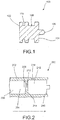
- Firing pin 100 may comprise first face 102 and second face 104 opposite first face 102. Nub 106 may extend from second face 104 and be configured to impact a primer, such as primer 302 (with momentary reference to FIG. 3 ). Firing pin 100 may further comprise an O-ring groove 108 configured to receive an O-ring, such as O-ring 112 (with momentary reference to FIG. 3 ). O-ring groove 108 may extend circumferentially around firing pin 100 and be proximate to second face 104.
- Firing pin 100 may further comprise shear pin groove 110 configured to receive a shear pin, such as shear pin 114 (with momentary reference to FIG. 3 ).
- Shear pin groove 110 may extend circumferentially around firing pin 100 and be situated between first face 102 and O-ring groove 108.
- Firing pin 100 may be made from various materials, including but not limited to, steel, aluminum, titanium alloys or other materials capable of withstanding impact with primer 302 with limited deformation.
- High explosive firing mechanism 200 may form a portion of an egress system for an aircraft, however, high explosive firing mechanism 200 is not limited in this regard.
- High explosive firing mechanism 200 may be configured to transfer an explosive signal in the direction depicted by the arrow in FIG. 2 .
- high explosive firing mechanism 200 may be configured to receive an explosive signal from an input component coupled to high explosive firing mechanism 200 and relay the signal to an output component coupled to high explosive firing mechanism 200.
- High explosive firing mechanism 200 may comprise a housing 202.
- housing 202 may comprise an exterior geometry in the shape of a cylinder or other suitable geometry configured to enclose firing pin 100.
- Housing 202 may comprise any suitable material capable of withstanding pressure forces resulting from combusting gases or forces from impact of primer 100 in housing 202.
- housing 202 such as steel, aluminum, titanium, alloys of the aforementioned or other materials.
- housing 202 may comprise an internal structure 204 configured to contain expanding gases and transfer an explosive signal.
- Housing 202 may comprise an input tube 206 comprising funnel portion 208, transition tube 210, and firing pin tube 212.
- Firing pin tube 212 may have a primer inlet 300.
- Input tube 206 may be configured to receive a high energy transfer line, such as for example, a high energy thin layer explosive, a detonating cord, an electrically initiated detonator, or the like.
- Funnel portion 208 may be configured to funnel the high energy transfer line into transition tube 210 where the high energy transfer line may terminate.
- Transition tube 210 may be situated between and be in fluid communication with firing pin tube 212 and input tube 206.
- Transition tube may be configured to transfer expanding gases from the high energy transfer line into firing pin tube 212.
- Firing pin tube 212 may comprise a first surface 214 and a second surface 216 opposite first surface 214.
- First surface 214 and second surface 216 may be configured to contain firing pin 100 in firing pin tube 212.
- firing pin 100 is depicted in firing pin tube 212 in a first position in accordance with various embodiments.
- first face 102 may be spaced apart from first surface 214 of firing pin tube 212.
- Second face 104 may be spaced apart from second surface 216.
- Firing pin 100 may comprise an O-ring 112 situated in O-ring groove 108 and a shear pin 114 extending through housing aperture 218 and into shear pin groove 110.
- O-ring 112 may be configured to seal gases and guide firing pin 100 as firing pin 100 travels through firing pin tube 212.
- Shear pin 114 may be configured to maintain firing pin 100 in the first position by mechanically inhibiting movement of firing pin 100 relative to housing 202.
- Second face 104 of firing pin 100 may be situated a distance d from second surface 216 of firing pin tube 212.
- distance d may be between 0.965 mm (0.038 inches) and 1.778 mm (0.070 inches).
- distance d may be such that nub 106 may at least partially extend into a primer inlet 300.
- Primer inlet 300 may contain primer 302, which may contain a pressure sensitive explosive capable of igniting in response to nub 106 impacting primer 302.
- Primer 302 be any suitable primer capable of initiating energetic devices, for example, generating initiators, rocket motor igniters, time delay initiators, or others.
- primer 302 may be in the form of a percussion primer, such as a percussion primer available under the trademark M42C1 from Olin Corporation, however primer 302 is not limited in this regard.
- firing pin 100 is depicted in firing pin tube 212 in a second position in various embodiments.
- combusting gases may enter transition tube 210 and portion of firing pin tube 212 behind first face 102 of firing pin 100.
- the combusting gases may raise the temperature of gases within transition tube 210 and firing pin tube 212, causing the gases to expand and exert a force on firing pin 100.
- forces continue to increase on firing pin 100.
- shear pin 114 may mechanically fail due to shear forces resulting from firing pin 100 pushing against shear pin 114.
- firing pin 100 may be accelerated through firing pin tube 212 to the second position.
- nub 106 may enter primer inlet 300 and impact primer 302.
- the impact of nub 106 on primer 302 may cause the pressure sensitive explosive in primer 302 to ignite, thereby igniting an energetic device coupled to high explosive firing mechanism 200.
- Forward momentum of firing pin 100 may be stopped in response to second face 104 of firing pin 100 contacting second surface 216 of firing pin tube 212.
- Distance d may be selected such that nub 106 extends into primer inlet 300 and the distance between second face 104 and second surface 216 are reduced in the first position.
- travel distance of firing pin 100 in firing pin tube 212 may be reduced.
- Limiting travel distance of firing pin 100 may reduce the velocity of firing pin 100 and may reduce the energy of the impact of second face 104 on second surface 216 and nub 106 on primer 302.
- the reduced impact energy may reduce the frequency of structural failures such as punctured primers. Punctured primers may result in formation of leak paths for gases within the system, thereby adversely affecting performance of downstream components.
- distance d must be selected such that impact energy of second face 104 on second surface 216 and nub 106 on primer 302 are reduced to minimize damage of the components, while still generating enough impact energy to ignite primer 302.
- distance d may also be selected such that nub 106 does not accidentally impact primer 302 while components vibrate during normal aircraft operation.
- Method 400 may comprise forming an input tube and firing pin tube within a housing (step 402). The method may further comprise placing an O-ring within an O-ring groove on a firing pin (step 404). The method may further comprise inserting the firing pin into the firing in tube (step 406). The method may further comprise inserting a shear pin through a housing aperture into a shear pin groove on the firing pin (step 408). The method may further comprise inserting a high energy transfer line into the input tube (step 410). The method may further comprise igniting the high energy transfer line (step 412). The method may further comprise impacting a primer cap with the firing pin (step 414). Method 400 is not limited in this regard. For example, any of the steps listed above may be performed in a different order.
- references to "one embodiment”, “an embodiment”, “various embodiments”, etc. indicate that the embodiment described may include a particular feature, structure, or characteristic, but every embodiment may not necessarily include the particular feature, structure, or characteristic. Moreover, such phrases are not necessarily referring to the same embodiment. Further, when a particular feature, structure, or characteristic is described in connection with an embodiment, it is submitted that it is within the knowledge of one skilled in the art to affect such feature, structure, or characteristic in connection with other embodiments whether or not explicitly described. After reading the description, it will be apparent to one skilled in the relevant art(s) how to implement the disclosure in alternative embodiments.
Landscapes
- Engineering & Computer Science (AREA)
- General Engineering & Computer Science (AREA)
- Mechanical Engineering (AREA)
- Aviation & Aerospace Engineering (AREA)
- Physics & Mathematics (AREA)
- Fluid Mechanics (AREA)
- Pressure Welding/Diffusion-Bonding (AREA)
- Connection Of Plates (AREA)
Abstract
Description
- This disclosure was made with Government support under Contract No. N0017411C0060 awarded by The United States Navy. The Government has certain rights in the disclosure.
- The present disclosure relates to high explosive firing mechanisms and methods, and more particularly, to high explosive firing mechanisms and methods in aircraft egress systems.
- Modern aircraft egress systems typically utilize high explosive detonating sources to transfer an explosive signal between components within the egress system. Some devices utilize this high explosive detonating source as an initiation stimulus for primer actuated devices. However, primer actuated devices benefit from a specific input energy to function reliably and without damage. High explosive detonating sources may exceed the required input energy, leading to damaged system components.
- A high explosive firing mechanism may comprise a housing comprising a firing pin tube having a primer inlet and a firing pin disposed within the firing pin tube, the firing pin comprising a nub, wherein the nub partially extends into the primer inlet.
- In various embodiments, the firing pin may further comprise a first face, a second face opposite the first face, an O-ring groove extending circumferentially around the firing pin and proximate to the second face, and a shear pin groove extending circumferentially around the firing pin and situated between the first face and O-ring groove. The nub may extend from the second face of the firing pin. The housing may further comprise a transition tube in fluid communication with the firing pin tube. The second face of the firing pin may be located a distance between 0.9652 and 1.778 mm (0.038 and 0.070 inches) from a second surface of the firing pin tube at a first position. The housing may further comprise an input tube in fluid communication with the transition tube. The nub may be configured to impact a primer contained in the primer inlet at a second position. The high explosive firing mechanism may further comprise a shear pin extending through a housing aperture into the shear pin groove and an O-ring situated within the O-ring groove. The shear pin may be configured to mechanically fail at a threshold force on the shear pin.
- An egress system for an aircraft may comprise a high explosive firing mechanism comprising a housing comprising a firing pin tube having a primer inlet, and a firing pin disposed within the firing pin tube, the firing pin comprising a nub, wherein the nub partially extends into the primer inlet.
- In various embodiments, the egress system may further comprise an input component and output component coupled to the high explosive firing mechanism. The firing pin may further comprise a first face, a second face opposite the first face, an O-ring groove extending circumferentially around the firing pin and proximate to the second face, and a shear pin groove extending circumferentially around the firing pin and situated between the first face and O-ring groove. The second face of the firing pin may be configured to contact a second surface of the firing pin tube at a second position. The second face of the firing pin may be located a distance between 0,9652 and 1.778 mm (0.038 and 0.070 inches) from a second surface of the firing pin tube at a first position. The housing may further comprise a transition tube in fluid communication with the firing pin tube and an input tube in fluid communication with the transition tube. The high explosive firing mechanism may further comprise a shear pin extending through a housing aperture into the shear pin groove and an O-ring situated within the O-ring groove. The shear pin may be configured to mechanically fail at a threshold force on the shear pin.
- A method of transferring a high explosive signal may comprise forming an input tube and firing pin tube within a housing, inserting a firing pin into the firing pin tube such that a nub of the firing pin extends into a primer inlet, and inserting a high energy transfer line into the input tube.
- In various embodiments, the method may further comprise igniting the high energy transfer line and impacting a primer with the firing pin.
- The foregoing features and elements may be combined in various combinations without exclusivity, unless expressly indicated otherwise. These features and elements as well as the operation thereof will become more apparent in light of the following description and the accompanying drawings. It should be understood, however, the following description and drawings are intended to be exemplary in nature and non-limiting.
- The accompanying drawings are included to provide a further understanding of the present disclosure and are incorporated in, and constitute a part of, this specification, illustrate various embodiments, and together with the description, serve to explain the principles of the disclosure.
-
FIG. 1 illustrates a cross-sectional view of a firing pin in accordance with various embodiments; -
FIG. 2 illustrates a cross-sectional view of a high explosive firing mechanism in accordance with various embodiments; -
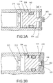
FIG. 3A illustrates a cross-sectional view of a firing pin positioned in a high explosive firing mechanism in a first position in accordance with various embodiments; -
FIG. 3B illustrates a cross-sectional view of a firing pin positioned in a high explosive firing mechanism in a second position in accordance with various embodiments. -
FIG. 4 depicts a flowchart illustrating a method of transferring a high explosive signal in accordance with various embodiments. - The detailed description of various embodiments herein makes reference to the accompanying drawings, which show various embodiments by way of illustration. While these various embodiments are described in sufficient detail to enable those skilled in the art to practice the disclosure, it should be understood that other embodiments may be realized and that logical, chemical, electrical, and mechanical changes may be made without departing from the scope of the invention as defined by the claims. Thus, the detailed description herein is presented for purposes of illustration only and not of limitation.
- For example, the steps recited in any of the method or process descriptions may be executed in any order and are not necessarily limited to the order presented. Furthermore, any reference to singular includes plural embodiments, and any reference to more than one component or step may include a singular embodiment or step. Also, any reference to attached, fixed, connected, or the like may include permanent, removable, temporary, partial, full, and/or any other possible attachment option. Additionally, any reference to without contact (or similar phrases) may also include reduced contact or minimal contact.
- For example, in the context of the present disclosure, methods, systems, and articles may find particular use in connection with aircraft egress systems. However, various aspects of the disclosed embodiments may be adapted for optimized performance in a variety of other systems. As such, numerous applications of the present disclosure may be realized.
- Referring to
FIG. 1 , a cross-sectional view of afiring pin 100 is depicted in accordance with various embodiments. Firingpin 100 may comprisefirst face 102 andsecond face 104 oppositefirst face 102.Nub 106 may extend fromsecond face 104 and be configured to impact a primer, such as primer 302 (with momentary reference toFIG. 3 ). Firingpin 100 may further comprise an O-ring groove 108 configured to receive an O-ring, such as O-ring 112 (with momentary reference toFIG. 3 ). O-ring groove 108 may extend circumferentially around firingpin 100 and be proximate tosecond face 104. Firingpin 100 may further compriseshear pin groove 110 configured to receive a shear pin, such as shear pin 114 (with momentary reference toFIG. 3 ).Shear pin groove 110 may extend circumferentially around firingpin 100 and be situated betweenfirst face 102 and O-ring groove 108. Firingpin 100 may be made from various materials, including but not limited to, steel, aluminum, titanium alloys or other materials capable of withstanding impact withprimer 302 with limited deformation. - Referring to
FIG. 2 , a cross-sectional view of highexplosive firing mechanism 200 is depicted in accordance with various embodiments. Highexplosive firing mechanism 200 may form a portion of an egress system for an aircraft, however, highexplosive firing mechanism 200 is not limited in this regard. Highexplosive firing mechanism 200 may be configured to transfer an explosive signal in the direction depicted by the arrow inFIG. 2 . For example, highexplosive firing mechanism 200 may be configured to receive an explosive signal from an input component coupled to highexplosive firing mechanism 200 and relay the signal to an output component coupled to highexplosive firing mechanism 200. Highexplosive firing mechanism 200 may comprise ahousing 202. In various embodiments,housing 202 may comprise an exterior geometry in the shape of a cylinder or other suitable geometry configured to enclosefiring pin 100.Housing 202 may comprise any suitable material capable of withstanding pressure forces resulting from combusting gases or forces from impact ofprimer 100 inhousing 202. For example,housing 202, such as steel, aluminum, titanium, alloys of the aforementioned or other materials. - With further reference to
FIG. 2 ,housing 202 may comprise aninternal structure 204 configured to contain expanding gases and transfer an explosive signal.Housing 202 may comprise aninput tube 206 comprisingfunnel portion 208,transition tube 210, andfiring pin tube 212.Firing pin tube 212 may have aprimer inlet 300.Input tube 206 may be configured to receive a high energy transfer line, such as for example, a high energy thin layer explosive, a detonating cord, an electrically initiated detonator, or the like.Funnel portion 208 may be configured to funnel the high energy transfer line intotransition tube 210 where the high energy transfer line may terminate.Transition tube 210 may be situated between and be in fluid communication withfiring pin tube 212 andinput tube 206. Transition tube may be configured to transfer expanding gases from the high energy transfer line intofiring pin tube 212.Firing pin tube 212 may comprise afirst surface 214 and asecond surface 216 oppositefirst surface 214.First surface 214 andsecond surface 216 may be configured to containfiring pin 100 in firingpin tube 212. - Referring to
FIG. 3A , firingpin 100 is depicted infiring pin tube 212 in a first position in accordance with various embodiments. In the first position,first face 102 may be spaced apart fromfirst surface 214 of firingpin tube 212.Second face 104 may be spaced apart fromsecond surface 216.Firing pin 100 may comprise an O-ring 112 situated in O-ring groove 108 and ashear pin 114 extending throughhousing aperture 218 and intoshear pin groove 110. O-ring 112 may be configured to seal gases and guidefiring pin 100 as firingpin 100 travels throughfiring pin tube 212.Shear pin 114 may be configured to maintainfiring pin 100 in the first position by mechanically inhibiting movement offiring pin 100 relative tohousing 202.Second face 104 offiring pin 100 may be situated a distance d fromsecond surface 216 of firingpin tube 212. For example in various embodiments, distance d may be between 0.965 mm (0.038 inches) and 1.778 mm (0.070 inches). In the first position, distance d may be such thatnub 106 may at least partially extend into aprimer inlet 300.Primer inlet 300 may containprimer 302, which may contain a pressure sensitive explosive capable of igniting in response tonub 106impacting primer 302.Primer 302 be any suitable primer capable of initiating energetic devices, for example, generating initiators, rocket motor igniters, time delay initiators, or others. In various embodiments,primer 302 may be in the form of a percussion primer, such as a percussion primer available under the trademark M42C1 from Olin Corporation, howeverprimer 302 is not limited in this regard. - Referring to
FIG. 3B ,firing pin 100 is depicted infiring pin tube 212 in a second position in various embodiments. In response to the high energy transfer line igniting withininput tube 206, combusting gases may entertransition tube 210 and portion offiring pin tube 212 behindfirst face 102 offiring pin 100. The combusting gases may raise the temperature of gases withintransition tube 210 andfiring pin tube 212, causing the gases to expand and exert a force on firingpin 100. As the gases continue to expand, forces continue to increase onfiring pin 100. Upon reaching a threshold force (for example 180 1bf (800 N))shear pin 114 may mechanically fail due to shear forces resulting from firingpin 100 pushing againstshear pin 114. In response, firingpin 100 may be accelerated throughfiring pin tube 212 to the second position. In the second position,nub 106 may enterprimer inlet 300 andimpact primer 302. The impact ofnub 106 onprimer 302 may cause the pressure sensitive explosive inprimer 302 to ignite, thereby igniting an energetic device coupled to highexplosive firing mechanism 200. Forward momentum offiring pin 100 may be stopped in response tosecond face 104 offiring pin 100 contactingsecond surface 216 of firingpin tube 212. - Distance d may be selected such that
nub 106 extends intoprimer inlet 300 and the distance betweensecond face 104 andsecond surface 216 are reduced in the first position. By limiting distance d in this manner, travel distance offiring pin 100 in firingpin tube 212 may be reduced. Limiting travel distance offiring pin 100 may reduce the velocity offiring pin 100 and may reduce the energy of the impact ofsecond face 104 onsecond surface 216 andnub 106 onprimer 302. The reduced impact energy may reduce the frequency of structural failures such as punctured primers. Punctured primers may result in formation of leak paths for gases within the system, thereby adversely affecting performance of downstream components. Accordingly, distance d must be selected such that impact energy ofsecond face 104 onsecond surface 216 andnub 106 onprimer 302 are reduced to minimize damage of the components, while still generating enough impact energy to igniteprimer 302. However, distance d may also be selected such thatnub 106 does not accidentally impactprimer 302 while components vibrate during normal aircraft operation. - A block diagram illustrating a
method 400 for transferring a high explosive signal such as through highexplosive firing mechanism 200, is depicted inFIG. 4 , in accordance with various embodiments.Method 400 may comprise forming an input tube and firing pin tube within a housing (step 402). The method may further comprise placing an O-ring within an O-ring groove on a firing pin (step 404). The method may further comprise inserting the firing pin into the firing in tube (step 406). The method may further comprise inserting a shear pin through a housing aperture into a shear pin groove on the firing pin (step 408). The method may further comprise inserting a high energy transfer line into the input tube (step 410). The method may further comprise igniting the high energy transfer line (step 412). The method may further comprise impacting a primer cap with the firing pin (step 414).Method 400 is not limited in this regard. For example, any of the steps listed above may be performed in a different order. - Benefits, other advantages, and solutions to problems have been described herein with regard to specific embodiments. Furthermore, the connecting lines shown in the various figures contained herein are intended to represent exemplary functional relationships and/or physical couplings between the various elements. It should be noted that many alternative or additional functional relationships or physical connections may be present in a practical system. However, the benefits, advantages, solutions to problems, and any elements that may cause any benefit, advantage, or solution to occur or become more pronounced are not to be construed as critical, required, or essential features or elements of the disclosure. The scope of the disclosure is accordingly to be limited by nothing other than the appended claims, in which reference to an element in the singular is not intended to mean "one and only one" unless explicitly so stated, but rather "one or more." Moreover, where a phrase similar to "at least one of A, B, or C" is used in the claims, it is intended that the phrase be interpreted to mean that A alone may be present in an embodiment, B alone may be present in an embodiment, C alone may be present in an embodiment, or that any combination of the elements A, B and C may be present in a single embodiment; for example, A and B, A and C, B and C, or A and B and C. Different cross-hatching is used throughout the figures to denote different parts but not necessarily to denote the same or different materials.
- Methods, systems, and computer-readable media are provided herein. In the detailed description herein, references to "one embodiment", "an embodiment", "various embodiments", etc., indicate that the embodiment described may include a particular feature, structure, or characteristic, but every embodiment may not necessarily include the particular feature, structure, or characteristic. Moreover, such phrases are not necessarily referring to the same embodiment. Further, when a particular feature, structure, or characteristic is described in connection with an embodiment, it is submitted that it is within the knowledge of one skilled in the art to affect such feature, structure, or characteristic in connection with other embodiments whether or not explicitly described. After reading the description, it will be apparent to one skilled in the relevant art(s) how to implement the disclosure in alternative embodiments.
Claims (14)
- A high explosive firing mechanism, comprising:a housing (202) comprising,a firing pin tube (212) having a primer inlet (300); anda firing pin (100) disposed within the firing pin tube, the firing pin comprising a nub (106), wherein the nub partially extends into the primer inlet.
- The high explosive firing mechanism of claim 1, wherein the firing pin further comprises a first face (102), a second face (104) opposite the first face, an O-ring groove (108) extending circumferentially around the firing pin and proximate to the second face, and a shear pin groove (110) extending circumferentially around the firing pin and situated between the first face and O-ring groove.
- The high explosive firing mechanism of claim 2, wherein the nub extends from the second face of the firing pin.
- The high explosive firing mechanism of claim 1, 2 or 3, wherein the housing further comprises a transition tube (210) in fluid communication with the firing pin tube.
- The high explosive firing mechanism of claim 2 or 3, or claim 4 when dependent on claim 2 or 3, wherein the second face of the firing pin is located a distance between 0.965 and 1.778 mm (0.038 and 0.070 inches) from a second surface of the firing pin tube at a first position.
- The high explosive firing mechanism of claim 4, wherein the housing further comprises an input tube (206) in fluid communication with the transition tube.
- The high explosive firing mechanism of any preceding claim, wherein the nub is configured to impact a primer (302) contained in the primer inlet at a second position.
- The high explosive firing mechanism of claim 2 or any claim dependent thereon, further comprising a shear pin (114) extending through a housing aperture into the shear pin groove (110) and an O-ring (112) situated within the O-ring groove.
- The high explosive firing mechanism of claim 8, wherein the shear pin is configured to mechanically fail at a threshold force on the shear pin.
- The high explosive firing mechanism of claim 2, wherein the second face of the firing pin is configured to contact a second surface of the firing pin tube at a second position.
- An egress system for an aircraft, comprising:a high explosive firing mechanism (200) as claimed in any preceding claim.
- The egress system of claim 11, further comprising an input component and output component coupled to the high explosive firing mechanism.
- A method of transferring a high explosive signal, comprising:forming an input tube and firing pin tube within a housing;inserting a firing pin into the firing pin tube such that a nub of the firing pin extends into a primer inlet; andinserting a high energy transfer line into the input tube.
- The method of claim 13, further comprising,
igniting the high energy transfer line; and
impacting a primer with the firing pin.
Applications Claiming Priority (1)
| Application Number | Priority Date | Filing Date | Title |
|---|---|---|---|
| US15/897,840 US10837747B2 (en) | 2018-02-15 | 2018-02-15 | High explosive firing mechanism |
Publications (2)
| Publication Number | Publication Date |
|---|---|
| EP3527929A1 true EP3527929A1 (en) | 2019-08-21 |
| EP3527929B1 EP3527929B1 (en) | 2024-06-05 |
Family
ID=64744488
Family Applications (1)
| Application Number | Title | Priority Date | Filing Date |
|---|---|---|---|
| EP18213155.7A Active EP3527929B1 (en) | 2018-02-15 | 2018-12-17 | High explosive firing mechanism |
Country Status (3)
| Country | Link |
|---|---|
| US (1) | US10837747B2 (en) |
| EP (1) | EP3527929B1 (en) |
| KR (1) | KR102644113B1 (en) |
Families Citing this family (6)
| Publication number | Priority date | Publication date | Assignee | Title |
|---|---|---|---|---|
| DE202017102257U1 (en) * | 2017-04-13 | 2017-06-20 | Fr. Sobbe Gmbh | Ignition device in compact version |
| US10837747B2 (en) * | 2018-02-15 | 2020-11-17 | Goodrich Corporation | High explosive firing mechanism |
| US11022414B2 (en) | 2019-09-27 | 2021-06-01 | Raytheon Company | Triggering device with safety valve and linkage |
| US10948274B1 (en) * | 2019-09-27 | 2021-03-16 | Raytheon Company | Heat-activated triggering device with bi-metal triggering element |
| US11892277B2 (en) * | 2020-08-11 | 2024-02-06 | Detotec North America | Non-electric initiator system |
| CA3203100A1 (en) * | 2020-12-22 | 2022-06-30 | James Robert SPARKES | Perimeter breach warning alarm |
Citations (7)
| Publication number | Priority date | Publication date | Assignee | Title |
|---|---|---|---|---|
| US3129663A (en) * | 1961-08-11 | 1964-04-21 | Aircraft Armaments Inc | Fittings for low energy detonating cord |
| US3610151A (en) * | 1969-05-09 | 1971-10-05 | Us Army | Nonelectric squib assembly |
| US3789761A (en) * | 1973-02-02 | 1974-02-05 | Us Army | Propagation transfer arrangement |
| EP0154532A2 (en) * | 1984-03-08 | 1985-09-11 | Halliburton Company | High explosive devices for use in wells and methods of detonating them |
| US6272996B1 (en) * | 1998-10-07 | 2001-08-14 | Shock Tube Systems, Inc. | In-line initiator and firing device assembly |
| US20130277108A1 (en) * | 2012-04-24 | 2013-10-24 | Fike Corporation | Energy transfer device |
| WO2016183255A1 (en) * | 2015-05-12 | 2016-11-17 | Cgs Group, Llc | Firing device |
Family Cites Families (83)
| Publication number | Priority date | Publication date | Assignee | Title |
|---|---|---|---|---|
| US831947A (en) * | 1905-04-15 | 1906-09-25 | Joseph W Graeme | Priming device. |
| US2394425A (en) * | 1941-03-20 | 1946-02-05 | Martin James | Quick-release hood for airplane cabins |
| US2873648A (en) * | 1953-05-07 | 1959-02-17 | Musser C Walton | Remote control fluid pressure responsive actuator |
| US4202269A (en) * | 1958-10-15 | 1980-05-13 | The United States Of America As Represented By The Secretary Of The Army | Fuze mine anti-personnel |
| US3855900A (en) * | 1959-01-07 | 1974-12-24 | Aircraft Armaments Inc | System for primer actuation of bolt |
| GB1046588A (en) * | 1964-09-11 | 1966-10-26 | Martin James | Improvements in or relating to multiple ejection seat installations |
| US3356025A (en) * | 1965-11-17 | 1967-12-05 | Stencel Aero Eng Corp | Pyrotechnic initiators |
| US3658006A (en) * | 1969-02-05 | 1972-04-25 | Explosive Tech | Explosively actuated egress and ingress device and method |
| US3575111A (en) * | 1969-04-28 | 1971-04-13 | Us Navy | Signaling device having manual firing means |
| US3640225A (en) * | 1969-06-20 | 1972-02-08 | Honeywell Inc | Fuze apparatus |
| GB1383511A (en) * | 1971-01-15 | 1974-02-12 | Hawker Siddeley Aviation Ltd | Aircraft canopy emergency |
| US3712221A (en) * | 1971-01-18 | 1973-01-23 | Us Army | Blast shield for explosive devices including linear shaped charges |
| US3847329A (en) * | 1972-08-31 | 1974-11-12 | Stanley Aviation Corp | Rocket escape apparatus |
| US3788227A (en) * | 1973-01-05 | 1974-01-29 | Us Navy | Jet ignition device for a pyrotechnic fuze |
| US3823669A (en) * | 1973-01-29 | 1974-07-16 | Us Army | Fail-safe hand grenade |
| US3912203A (en) * | 1974-01-02 | 1975-10-14 | Us Army | Rocket catapult aircraft escape arrangement |
| US3885761A (en) * | 1974-03-05 | 1975-05-27 | Jet Research Center | Aircraft emergency egress system |
| AT350453B (en) * | 1974-03-19 | 1979-06-11 | Diehl Fa | BREAK-AWAY WITH REDUCED SPARK JET |
| US3893367A (en) * | 1974-06-10 | 1975-07-08 | Us Navy | Mechanically initiated igniter |
| DE2443793C2 (en) * | 1974-09-13 | 1986-05-07 | Dynamit Nobel Ag, 5210 Troisdorf | Combined primer cap |
| DE2504907A1 (en) * | 1975-02-06 | 1976-08-19 | Dynamit Nobel Ag | DRIVING CHARGE LIGHTER WITH STRIKING PIECE |
| US4099465A (en) * | 1976-12-17 | 1978-07-11 | The United States Of America As Represented By The Secretary Of The Navy | Ignition device for missile motors |
| DE2723983C2 (en) * | 1977-05-27 | 1984-09-27 | Rheinmetall GmbH, 4000 Düsseldorf | Propellant charge lighter for caseless cartridges of separately loaded ammunition |
| US4405104A (en) * | 1977-12-14 | 1983-09-20 | The Secretary Of State For Defence In Her Britannic Majesty's Government Of The United Kingdom Of Great Britain And Northern Ireland | Panel breaking apparatus |
| CH622885A5 (en) * | 1978-07-27 | 1981-04-30 | Redon Trust | |
| DE2832879A1 (en) * | 1978-07-27 | 1980-02-14 | Dynamit Nobel Ag | DRIVE CHARGE LIGHT |
| FR2445799A1 (en) * | 1979-01-04 | 1980-08-01 | Aerospatiale | ICE PROVIDED WITH A PYROTECHNIC CUTTING DEVICE |
| US4301707A (en) * | 1979-10-29 | 1981-11-24 | Mcdonnell Douglas Corporation | Embedded explosive severance of non-metallic materials |
| US4407468A (en) * | 1981-04-30 | 1983-10-04 | The United States Of America As Represented By The Administrator Of The National Aeronautics And Space Administration | Explosively activated egress area |
| US4479436A (en) * | 1982-01-15 | 1984-10-30 | Wilson Douglas G | Device for igniting safety fuse |
| US4495867A (en) * | 1982-06-18 | 1985-01-29 | E. I. Du Pont De Nemours And Company | Assembly for initiating explosives with low-energy detonating cord |
| FR2534369B1 (en) * | 1982-10-08 | 1987-03-20 | Brandt Francois | PERFORATING EXPLOSIVE PROJECTILE IN CARTRIDGE |
| FR2542697B1 (en) * | 1983-03-14 | 1986-03-21 | Dassault Avions | METHOD AND PYROTECHNIC DEVICE FOR EJECTION OUTSIDE AN AIRPLANE |
| US4483250A (en) * | 1983-04-14 | 1984-11-20 | Thiokol Corporation | Flare manual safety device |
| US4676163A (en) * | 1984-08-22 | 1987-06-30 | Morton Thiokol, Inc. | Double-path detonation tube inertia igniter |
| US4590840A (en) * | 1984-11-09 | 1986-05-27 | Federal Cartridge Corporation | Flash hole closure for primer battery cups |
| DE3629371A1 (en) * | 1986-04-26 | 1987-10-29 | Dynamit Nobel Ag | Explosive detonators |
| US4688466A (en) * | 1986-09-11 | 1987-08-25 | Explosive Technology, Inc. | Explosive initiator and method |
| FR2634171B1 (en) * | 1988-07-13 | 1990-09-28 | Aerospatiale | PYROTECHNIC SYSTEM FOR PROVIDING A EMERGENCY EXIT IN A WALL OF AN AIRCRAFT AND AIRCRAFT EQUIPPED WITH SAID SYSTEM |
| US5104067A (en) * | 1990-05-14 | 1992-04-14 | Mcdonnell Douglas Corporation | Detonating cord powered canopy breakers |
| DE4124490A1 (en) * | 1991-07-24 | 1993-01-28 | Dynamit Nobel Ag | PLASTIC CARTRIDGE AND PLASTIC CARTRIDGE TAPE MAGAZINE |
| US5170004A (en) * | 1991-08-05 | 1992-12-08 | Teledyne Industries, Inc. | Hydraulic severance shaped explosive |
| US5365851A (en) * | 1992-08-07 | 1994-11-22 | The Ensign-Bickford Company | Initiator device |
| US5753849A (en) * | 1996-09-19 | 1998-05-19 | Propellex Corporation | Gas-operated timing demolition delay |
| US5954296A (en) * | 1998-02-18 | 1999-09-21 | Teledyne Industries, Inc. | Aircraft canopy fracture system |
| US6640719B1 (en) * | 1999-01-11 | 2003-11-04 | The United States Of America As Represented By The Secretary Of The Army | Fuze explosive train device and method |
| FR2812937B1 (en) * | 2000-08-14 | 2005-03-04 | Denel Proprietary Ltd | FORCE AMPLIFIER PRIMING DEVICE FOR CARTRIDGE |
| US6675896B2 (en) * | 2001-03-08 | 2004-01-13 | Halliburton Energy Services, Inc. | Detonation transfer subassembly and method for use of same |
| US7246558B2 (en) * | 2002-03-01 | 2007-07-24 | Mccormick Selph, Inc. | Rapid deflagration cord (RDC) ordnance transfer lines |
| JP4009188B2 (en) | 2002-12-12 | 2007-11-14 | 株式会社石川製作所 | Ignition device |
| US6752355B1 (en) * | 2003-02-13 | 2004-06-22 | The Boeing Company | Method and system for emergency escape from an aircraft |
| US6845947B1 (en) * | 2003-10-09 | 2005-01-25 | The United States Of America As Represented By The Secretary Of The Navy | Aircraft canopy jettison apparatus with airbag |
| US7451700B1 (en) * | 2004-04-14 | 2008-11-18 | Raytheon Company | Detonator system having linear actuator |
| US8042471B2 (en) * | 2005-02-28 | 2011-10-25 | Lockheed Martin Corporation | Safe and arm device and explosive device incorporating same |
| US7117796B1 (en) * | 2005-12-29 | 2006-10-10 | The United States Of America As Represented By The Secretary Of The Navy | Igniter for exothermic torch rod |
| US8002026B2 (en) * | 2006-10-26 | 2011-08-23 | Alliant Techsystems Inc. | Methods and apparatuses for electronic time delay and systems including same |
| US7437995B2 (en) * | 2006-11-15 | 2008-10-21 | Omnitek Partners Llc | Axially compact mechanical igniter for thermal batteries and the like |
| US20080134922A1 (en) * | 2006-12-06 | 2008-06-12 | Grattan Antony F | Thermally Activated Well Perforating Safety System |
| WO2009039255A1 (en) * | 2007-09-19 | 2009-03-26 | Albemarle Corporation | Methods for production of 1,2,4-triazol-3-one |
| UA98024C2 (en) * | 2007-12-07 | 2012-04-10 | ДИНАМИТ НОБЕЛЬ ДИФЕНС ГмбХ | Thermally initiated triggering of aerosol fire extinguisher and method for actuating generator of fire-extinguishing aerosol |
| BRMU8903104U2 (en) * | 2008-04-28 | 2013-01-08 | Blew Chip Holdings Pty Ltd | explosive compound upgrade |
| US8585838B1 (en) * | 2008-04-28 | 2013-11-19 | Blew Chip Holdings Pty Ltd. | Explosive composition |
| US7832335B2 (en) * | 2008-09-21 | 2010-11-16 | Omnitek Partners Llc | Axially compact and low-volume mechanical igniter for thermal batteries and the like |
| WO2010039119A1 (en) * | 2008-09-30 | 2010-04-08 | Sikorsky Aircraft Corporation | Pyrotechnic egress system |
| GB2466257B (en) * | 2008-12-17 | 2013-08-21 | Olympic Technologies Ltd | Safety system |
| FR2944348A1 (en) * | 2009-04-10 | 2010-10-15 | Nexter Munitions | PERCUSSION MUNITING DEVICE |
| US8230770B1 (en) * | 2009-09-22 | 2012-07-31 | The United States Of America As Represented By The Secretary Of The Navy | Apparatus to energetically remove a ballistic tolerant window |
| US8061656B1 (en) * | 2009-09-22 | 2011-11-22 | The United States Of America As Represented By The Secretary Of The Navy | Hinge apparatus with an actuatable assembly |
| US8250980B1 (en) * | 2010-05-20 | 2012-08-28 | The United States Of America As Represented By The Secretary Of The Navy | Release mechanism apparatus |
| FR2971048B1 (en) * | 2011-01-31 | 2013-01-11 | Nexter Munitions | SECURITY AND ARMING DEVICE WITH A CASSABLE LATCH |
| JP5707171B2 (en) | 2011-02-25 | 2015-04-22 | 任天堂株式会社 | COMMUNICATION CONTROL DEVICE, COMMUNICATION CONTROL PROGRAM, COMMUNICATION CONTROL METHOD, AND INFORMATION PROCESSING SYSTEM |
| US8997773B2 (en) * | 2011-05-13 | 2015-04-07 | Cathleen Reda | Pressure discharge mechanism for closed vessels |
| US9488456B2 (en) * | 2012-01-13 | 2016-11-08 | Los Alamos National Security, Llc | Geologic fracturing method and resulting fractured geologic structure |
| WO2013110982A2 (en) * | 2012-01-25 | 2013-08-01 | International Technologies, Llc | Booster explosive support device |
| US9765271B2 (en) * | 2012-06-27 | 2017-09-19 | James J. Myrick | Nanoparticles, compositions, manufacture and applications |
| US10246982B2 (en) * | 2013-07-15 | 2019-04-02 | Triad National Security, Llc | Casings for use in a system for fracturing rock within a bore |
| CA2929500A1 (en) * | 2013-11-05 | 2015-05-14 | Fowlds 3 Limited | A cartridge |
| US20150284926A1 (en) | 2014-04-03 | 2015-10-08 | David Y. Du | Explosive pile device for increasing pile capacity |
| IL240777B (en) * | 2015-08-23 | 2019-10-31 | Ispra Ltd | Firearm projectile usable as hand grenade |
| US10384788B2 (en) * | 2016-04-18 | 2019-08-20 | Goodrich Corporation | Multiple aircraft seat ejection mode selector |
| EP3673227B1 (en) * | 2017-08-24 | 2021-06-23 | River Front Services, Inc. | Explosive detonating system and components |
| US10837747B2 (en) * | 2018-02-15 | 2020-11-17 | Goodrich Corporation | High explosive firing mechanism |
| US20190249971A1 (en) * | 2018-02-15 | 2019-08-15 | Goodrich Corporation | Low energy explosive transfer adapter |
-
2018
- 2018-02-15 US US15/897,840 patent/US10837747B2/en active Active
- 2018-11-02 KR KR1020180133268A patent/KR102644113B1/en active Active
- 2018-12-17 EP EP18213155.7A patent/EP3527929B1/en active Active
Patent Citations (7)
| Publication number | Priority date | Publication date | Assignee | Title |
|---|---|---|---|---|
| US3129663A (en) * | 1961-08-11 | 1964-04-21 | Aircraft Armaments Inc | Fittings for low energy detonating cord |
| US3610151A (en) * | 1969-05-09 | 1971-10-05 | Us Army | Nonelectric squib assembly |
| US3789761A (en) * | 1973-02-02 | 1974-02-05 | Us Army | Propagation transfer arrangement |
| EP0154532A2 (en) * | 1984-03-08 | 1985-09-11 | Halliburton Company | High explosive devices for use in wells and methods of detonating them |
| US6272996B1 (en) * | 1998-10-07 | 2001-08-14 | Shock Tube Systems, Inc. | In-line initiator and firing device assembly |
| US20130277108A1 (en) * | 2012-04-24 | 2013-10-24 | Fike Corporation | Energy transfer device |
| WO2016183255A1 (en) * | 2015-05-12 | 2016-11-17 | Cgs Group, Llc | Firing device |
Also Published As
| Publication number | Publication date |
|---|---|
| KR102644113B1 (en) | 2024-03-06 |
| US10837747B2 (en) | 2020-11-17 |
| US20190249970A1 (en) | 2019-08-15 |
| KR20190098908A (en) | 2019-08-23 |
| EP3527929B1 (en) | 2024-06-05 |
Similar Documents
| Publication | Publication Date | Title |
|---|---|---|
| EP3527929B1 (en) | High explosive firing mechanism | |
| US3486410A (en) | Explosive severance means | |
| US3238876A (en) | Method for through-bulkhead shock initiation | |
| AU2013287267B2 (en) | Energy transfer device | |
| KR101494393B1 (en) | Dual thrust rocket propulsion machinery | |
| CN110657721A (en) | Inner-environment self-adaptive small-caliber missile remote dissociation protection MEMS safety system and method | |
| EP3527930A1 (en) | Low energy explosive transfer adapter | |
| CN109186344B (en) | A single-caliber universal MEMS safety system and method | |
| US10760887B2 (en) | Detonation transfer assembly | |
| KR101778168B1 (en) | Initiator for rocket motor | |
| CN102735118B (en) | Electric pin pusher for fuse capable of pushing safety pin to move | |
| US5959236A (en) | Through bulkhead initiator | |
| CN110985237A (en) | Connecting and fixing device for failure at high temperature based on memory alloy technology and application method | |
| US9995563B2 (en) | Cartridge with safety fuse in the drive system, and method for producing it | |
| US2703531A (en) | Fuze for projectiles | |
| US10385981B2 (en) | Energetic one way sequence termination valve | |
| EP4109036B1 (en) | Time delay systems, methods, and devices | |
| CN102735119B (en) | Electric pin pusher for fuse capable of pushing turntable to rotate | |
| US2996990A (en) | Explosive actuator | |
| US11598618B1 (en) | Time delay systems, methods, and devices | |
| US2981183A (en) | Tail initiation with nose fuzes | |
| RU2728907C1 (en) | Device for connection and subsequent separation of structural elements | |
| KR102416247B1 (en) | Double detonation apparatus for warhead | |
| RU2229617C1 (en) | Solid-propellant rocket engine | |
| RU2708755C1 (en) | Solid-propellant gas generator |
Legal Events
| Date | Code | Title | Description |
|---|---|---|---|
| PUAI | Public reference made under article 153(3) epc to a published international application that has entered the european phase |
Free format text: ORIGINAL CODE: 0009012 |
|
| STAA | Information on the status of an ep patent application or granted ep patent |
Free format text: STATUS: THE APPLICATION HAS BEEN PUBLISHED |
|
| AK | Designated contracting states |
Kind code of ref document: A1 Designated state(s): AL AT BE BG CH CY CZ DE DK EE ES FI FR GB GR HR HU IE IS IT LI LT LU LV MC MK MT NL NO PL PT RO RS SE SI SK SM TR |
|
| AX | Request for extension of the european patent |
Extension state: BA ME |
|
| STAA | Information on the status of an ep patent application or granted ep patent |
Free format text: STATUS: REQUEST FOR EXAMINATION WAS MADE |
|
| 17P | Request for examination filed |
Effective date: 20191118 |
|
| RBV | Designated contracting states (corrected) |
Designated state(s): AL AT BE BG CH CY CZ DE DK EE ES FI FR GB GR HR HU IE IS IT LI LT LU LV MC MK MT NL NO PL PT RO RS SE SI SK SM TR |
|
| STAA | Information on the status of an ep patent application or granted ep patent |
Free format text: STATUS: EXAMINATION IS IN PROGRESS |
|
| 17Q | First examination report despatched |
Effective date: 20220217 |
|
| P01 | Opt-out of the competence of the unified patent court (upc) registered |
Effective date: 20230922 |
|
| GRAP | Despatch of communication of intention to grant a patent |
Free format text: ORIGINAL CODE: EPIDOSNIGR1 |
|
| STAA | Information on the status of an ep patent application or granted ep patent |
Free format text: STATUS: GRANT OF PATENT IS INTENDED |
|
| INTG | Intention to grant announced |
Effective date: 20240130 |
|
| GRAS | Grant fee paid |
Free format text: ORIGINAL CODE: EPIDOSNIGR3 |
|
| GRAA | (expected) grant |
Free format text: ORIGINAL CODE: 0009210 |
|
| STAA | Information on the status of an ep patent application or granted ep patent |
Free format text: STATUS: THE PATENT HAS BEEN GRANTED |
|
| AK | Designated contracting states |
Kind code of ref document: B1 Designated state(s): AL AT BE BG CH CY CZ DE DK EE ES FI FR GB GR HR HU IE IS IT LI LT LU LV MC MK MT NL NO PL PT RO RS SE SI SK SM TR |
|
| REG | Reference to a national code |
Ref country code: GB Ref legal event code: FG4D |
|
| REG | Reference to a national code |
Ref country code: CH Ref legal event code: EP |
|
| REG | Reference to a national code |
Ref country code: DE Ref legal event code: R096 Ref document number: 602018070252 Country of ref document: DE |
|
| REG | Reference to a national code |
Ref country code: IE Ref legal event code: FG4D |
|
| REG | Reference to a national code |
Ref country code: LT Ref legal event code: MG9D |
|
| PG25 | Lapsed in a contracting state [announced via postgrant information from national office to epo] |
Ref country code: BG Free format text: LAPSE BECAUSE OF FAILURE TO SUBMIT A TRANSLATION OF THE DESCRIPTION OR TO PAY THE FEE WITHIN THE PRESCRIBED TIME-LIMIT Effective date: 20240605 |
|
| REG | Reference to a national code |
Ref country code: NL Ref legal event code: MP Effective date: 20240605 |
|
| PG25 | Lapsed in a contracting state [announced via postgrant information from national office to epo] |
Ref country code: FI Free format text: LAPSE BECAUSE OF FAILURE TO SUBMIT A TRANSLATION OF THE DESCRIPTION OR TO PAY THE FEE WITHIN THE PRESCRIBED TIME-LIMIT Effective date: 20240605 Ref country code: HR Free format text: LAPSE BECAUSE OF FAILURE TO SUBMIT A TRANSLATION OF THE DESCRIPTION OR TO PAY THE FEE WITHIN THE PRESCRIBED TIME-LIMIT Effective date: 20240605 |
|
| PG25 | Lapsed in a contracting state [announced via postgrant information from national office to epo] |
Ref country code: GR Free format text: LAPSE BECAUSE OF FAILURE TO SUBMIT A TRANSLATION OF THE DESCRIPTION OR TO PAY THE FEE WITHIN THE PRESCRIBED TIME-LIMIT Effective date: 20240906 |
|
| PG25 | Lapsed in a contracting state [announced via postgrant information from national office to epo] |
Ref country code: ES Free format text: LAPSE BECAUSE OF FAILURE TO SUBMIT A TRANSLATION OF THE DESCRIPTION OR TO PAY THE FEE WITHIN THE PRESCRIBED TIME-LIMIT Effective date: 20240605 |
|
| PG25 | Lapsed in a contracting state [announced via postgrant information from national office to epo] |
Ref country code: LV Free format text: LAPSE BECAUSE OF FAILURE TO SUBMIT A TRANSLATION OF THE DESCRIPTION OR TO PAY THE FEE WITHIN THE PRESCRIBED TIME-LIMIT Effective date: 20240605 |
|
| PG25 | Lapsed in a contracting state [announced via postgrant information from national office to epo] |
Ref country code: NO Free format text: LAPSE BECAUSE OF FAILURE TO SUBMIT A TRANSLATION OF THE DESCRIPTION OR TO PAY THE FEE WITHIN THE PRESCRIBED TIME-LIMIT Effective date: 20240905 Ref country code: LV Free format text: LAPSE BECAUSE OF FAILURE TO SUBMIT A TRANSLATION OF THE DESCRIPTION OR TO PAY THE FEE WITHIN THE PRESCRIBED TIME-LIMIT Effective date: 20240605 Ref country code: HR Free format text: LAPSE BECAUSE OF FAILURE TO SUBMIT A TRANSLATION OF THE DESCRIPTION OR TO PAY THE FEE WITHIN THE PRESCRIBED TIME-LIMIT Effective date: 20240605 Ref country code: GR Free format text: LAPSE BECAUSE OF FAILURE TO SUBMIT A TRANSLATION OF THE DESCRIPTION OR TO PAY THE FEE WITHIN THE PRESCRIBED TIME-LIMIT Effective date: 20240906 Ref country code: FI Free format text: LAPSE BECAUSE OF FAILURE TO SUBMIT A TRANSLATION OF THE DESCRIPTION OR TO PAY THE FEE WITHIN THE PRESCRIBED TIME-LIMIT Effective date: 20240605 Ref country code: ES Free format text: LAPSE BECAUSE OF FAILURE TO SUBMIT A TRANSLATION OF THE DESCRIPTION OR TO PAY THE FEE WITHIN THE PRESCRIBED TIME-LIMIT Effective date: 20240605 Ref country code: BG Free format text: LAPSE BECAUSE OF FAILURE TO SUBMIT A TRANSLATION OF THE DESCRIPTION OR TO PAY THE FEE WITHIN THE PRESCRIBED TIME-LIMIT Effective date: 20240605 Ref country code: RS Free format text: LAPSE BECAUSE OF FAILURE TO SUBMIT A TRANSLATION OF THE DESCRIPTION OR TO PAY THE FEE WITHIN THE PRESCRIBED TIME-LIMIT Effective date: 20240905 |
|
| PG25 | Lapsed in a contracting state [announced via postgrant information from national office to epo] |
Ref country code: NL Free format text: LAPSE BECAUSE OF FAILURE TO SUBMIT A TRANSLATION OF THE DESCRIPTION OR TO PAY THE FEE WITHIN THE PRESCRIBED TIME-LIMIT Effective date: 20240605 |
|
| REG | Reference to a national code |
Ref country code: AT Ref legal event code: MK05 Ref document number: 1692744 Country of ref document: AT Kind code of ref document: T Effective date: 20240605 |
|
| PG25 | Lapsed in a contracting state [announced via postgrant information from national office to epo] |
Ref country code: NL Free format text: LAPSE BECAUSE OF FAILURE TO SUBMIT A TRANSLATION OF THE DESCRIPTION OR TO PAY THE FEE WITHIN THE PRESCRIBED TIME-LIMIT Effective date: 20240605 |
|
| PG25 | Lapsed in a contracting state [announced via postgrant information from national office to epo] |
Ref country code: PT Free format text: LAPSE BECAUSE OF FAILURE TO SUBMIT A TRANSLATION OF THE DESCRIPTION OR TO PAY THE FEE WITHIN THE PRESCRIBED TIME-LIMIT Effective date: 20241007 |
|
| PG25 | Lapsed in a contracting state [announced via postgrant information from national office to epo] |
Ref country code: PT Free format text: LAPSE BECAUSE OF FAILURE TO SUBMIT A TRANSLATION OF THE DESCRIPTION OR TO PAY THE FEE WITHIN THE PRESCRIBED TIME-LIMIT Effective date: 20241007 |
|
| PG25 | Lapsed in a contracting state [announced via postgrant information from national office to epo] |
Ref country code: PL Free format text: LAPSE BECAUSE OF FAILURE TO SUBMIT A TRANSLATION OF THE DESCRIPTION OR TO PAY THE FEE WITHIN THE PRESCRIBED TIME-LIMIT Effective date: 20240605 |
|
| PG25 | Lapsed in a contracting state [announced via postgrant information from national office to epo] |
Ref country code: EE Free format text: LAPSE BECAUSE OF FAILURE TO SUBMIT A TRANSLATION OF THE DESCRIPTION OR TO PAY THE FEE WITHIN THE PRESCRIBED TIME-LIMIT Effective date: 20240605 |
|
| PG25 | Lapsed in a contracting state [announced via postgrant information from national office to epo] |
Ref country code: AT Free format text: LAPSE BECAUSE OF FAILURE TO SUBMIT A TRANSLATION OF THE DESCRIPTION OR TO PAY THE FEE WITHIN THE PRESCRIBED TIME-LIMIT Effective date: 20240605 Ref country code: IS Free format text: LAPSE BECAUSE OF FAILURE TO SUBMIT A TRANSLATION OF THE DESCRIPTION OR TO PAY THE FEE WITHIN THE PRESCRIBED TIME-LIMIT Effective date: 20241005 |
|
| PG25 | Lapsed in a contracting state [announced via postgrant information from national office to epo] |
Ref country code: CZ Free format text: LAPSE BECAUSE OF FAILURE TO SUBMIT A TRANSLATION OF THE DESCRIPTION OR TO PAY THE FEE WITHIN THE PRESCRIBED TIME-LIMIT Effective date: 20240605 |
|
| PG25 | Lapsed in a contracting state [announced via postgrant information from national office to epo] |
Ref country code: RO Free format text: LAPSE BECAUSE OF FAILURE TO SUBMIT A TRANSLATION OF THE DESCRIPTION OR TO PAY THE FEE WITHIN THE PRESCRIBED TIME-LIMIT Effective date: 20240605 Ref country code: SK Free format text: LAPSE BECAUSE OF FAILURE TO SUBMIT A TRANSLATION OF THE DESCRIPTION OR TO PAY THE FEE WITHIN THE PRESCRIBED TIME-LIMIT Effective date: 20240605 |
|
| PG25 | Lapsed in a contracting state [announced via postgrant information from national office to epo] |
Ref country code: SM Free format text: LAPSE BECAUSE OF FAILURE TO SUBMIT A TRANSLATION OF THE DESCRIPTION OR TO PAY THE FEE WITHIN THE PRESCRIBED TIME-LIMIT Effective date: 20240605 |
|
| PG25 | Lapsed in a contracting state [announced via postgrant information from national office to epo] |
Ref country code: SM Free format text: LAPSE BECAUSE OF FAILURE TO SUBMIT A TRANSLATION OF THE DESCRIPTION OR TO PAY THE FEE WITHIN THE PRESCRIBED TIME-LIMIT Effective date: 20240605 Ref country code: SK Free format text: LAPSE BECAUSE OF FAILURE TO SUBMIT A TRANSLATION OF THE DESCRIPTION OR TO PAY THE FEE WITHIN THE PRESCRIBED TIME-LIMIT Effective date: 20240605 Ref country code: RO Free format text: LAPSE BECAUSE OF FAILURE TO SUBMIT A TRANSLATION OF THE DESCRIPTION OR TO PAY THE FEE WITHIN THE PRESCRIBED TIME-LIMIT Effective date: 20240605 Ref country code: PL Free format text: LAPSE BECAUSE OF FAILURE TO SUBMIT A TRANSLATION OF THE DESCRIPTION OR TO PAY THE FEE WITHIN THE PRESCRIBED TIME-LIMIT Effective date: 20240605 Ref country code: IS Free format text: LAPSE BECAUSE OF FAILURE TO SUBMIT A TRANSLATION OF THE DESCRIPTION OR TO PAY THE FEE WITHIN THE PRESCRIBED TIME-LIMIT Effective date: 20241005 Ref country code: EE Free format text: LAPSE BECAUSE OF FAILURE TO SUBMIT A TRANSLATION OF THE DESCRIPTION OR TO PAY THE FEE WITHIN THE PRESCRIBED TIME-LIMIT Effective date: 20240605 Ref country code: CZ Free format text: LAPSE BECAUSE OF FAILURE TO SUBMIT A TRANSLATION OF THE DESCRIPTION OR TO PAY THE FEE WITHIN THE PRESCRIBED TIME-LIMIT Effective date: 20240605 Ref country code: AT Free format text: LAPSE BECAUSE OF FAILURE TO SUBMIT A TRANSLATION OF THE DESCRIPTION OR TO PAY THE FEE WITHIN THE PRESCRIBED TIME-LIMIT Effective date: 20240605 |
|
| PG25 | Lapsed in a contracting state [announced via postgrant information from national office to epo] |
Ref country code: IT Free format text: LAPSE BECAUSE OF FAILURE TO SUBMIT A TRANSLATION OF THE DESCRIPTION OR TO PAY THE FEE WITHIN THE PRESCRIBED TIME-LIMIT Effective date: 20240605 |
|
| REG | Reference to a national code |
Ref country code: DE Ref legal event code: R097 Ref document number: 602018070252 Country of ref document: DE |
|
| PLBE | No opposition filed within time limit |
Free format text: ORIGINAL CODE: 0009261 |
|
| STAA | Information on the status of an ep patent application or granted ep patent |
Free format text: STATUS: NO OPPOSITION FILED WITHIN TIME LIMIT |
|
| PG25 | Lapsed in a contracting state [announced via postgrant information from national office to epo] |
Ref country code: DK Free format text: LAPSE BECAUSE OF FAILURE TO SUBMIT A TRANSLATION OF THE DESCRIPTION OR TO PAY THE FEE WITHIN THE PRESCRIBED TIME-LIMIT Effective date: 20240605 |
|
| 26N | No opposition filed |
Effective date: 20250306 |
|
| PG25 | Lapsed in a contracting state [announced via postgrant information from national office to epo] |
Ref country code: MC Free format text: LAPSE BECAUSE OF FAILURE TO SUBMIT A TRANSLATION OF THE DESCRIPTION OR TO PAY THE FEE WITHIN THE PRESCRIBED TIME-LIMIT Effective date: 20240605 |
|
| REG | Reference to a national code |
Ref country code: CH Ref legal event code: PL |
|
| PG25 | Lapsed in a contracting state [announced via postgrant information from national office to epo] |
Ref country code: LU Free format text: LAPSE BECAUSE OF NON-PAYMENT OF DUE FEES Effective date: 20241217 |
|
| PG25 | Lapsed in a contracting state [announced via postgrant information from national office to epo] |
Ref country code: SE Free format text: LAPSE BECAUSE OF FAILURE TO SUBMIT A TRANSLATION OF THE DESCRIPTION OR TO PAY THE FEE WITHIN THE PRESCRIBED TIME-LIMIT Effective date: 20240605 |
|
| REG | Reference to a national code |
Ref country code: BE Ref legal event code: MM Effective date: 20241231 |
|
| PG25 | Lapsed in a contracting state [announced via postgrant information from national office to epo] |
Ref country code: BE Free format text: LAPSE BECAUSE OF NON-PAYMENT OF DUE FEES Effective date: 20241231 |
|
| PG25 | Lapsed in a contracting state [announced via postgrant information from national office to epo] |
Ref country code: CH Free format text: LAPSE BECAUSE OF NON-PAYMENT OF DUE FEES Effective date: 20241231 |
|
| PG25 | Lapsed in a contracting state [announced via postgrant information from national office to epo] |
Ref country code: IE Free format text: LAPSE BECAUSE OF NON-PAYMENT OF DUE FEES Effective date: 20241217 |
|
| PGFP | Annual fee paid to national office [announced via postgrant information from national office to epo] |
Ref country code: DE Payment date: 20251126 Year of fee payment: 8 |
|
| PGFP | Annual fee paid to national office [announced via postgrant information from national office to epo] |
Ref country code: GB Payment date: 20251120 Year of fee payment: 8 |
|
| PGFP | Annual fee paid to national office [announced via postgrant information from national office to epo] |
Ref country code: FR Payment date: 20251120 Year of fee payment: 8 |