EP3527906A1 - Indoor unit of air conditioner - Google Patents
Indoor unit of air conditioner Download PDFInfo
- Publication number
- EP3527906A1 EP3527906A1 EP18798858.9A EP18798858A EP3527906A1 EP 3527906 A1 EP3527906 A1 EP 3527906A1 EP 18798858 A EP18798858 A EP 18798858A EP 3527906 A1 EP3527906 A1 EP 3527906A1
- Authority
- EP
- European Patent Office
- Prior art keywords
- flap
- claw portion
- main body
- lower claw
- indoor unit
- Prior art date
- Legal status (The legal status is an assumption and is not a legal conclusion. Google has not performed a legal analysis and makes no representation as to the accuracy of the status listed.)
- Withdrawn
Links
- 210000000078 claw Anatomy 0.000 claims abstract description 91
- 230000037431 insertion Effects 0.000 abstract description 31
- 238000003780 insertion Methods 0.000 abstract description 31
- 238000004378 air conditioning Methods 0.000 description 9
- 238000007664 blowing Methods 0.000 description 4
- 230000007935 neutral effect Effects 0.000 description 3
- 238000005452 bending Methods 0.000 description 2
- 230000000694 effects Effects 0.000 description 2
Images




Classifications
-
- F—MECHANICAL ENGINEERING; LIGHTING; HEATING; WEAPONS; BLASTING
- F24—HEATING; RANGES; VENTILATING
- F24F—AIR-CONDITIONING; AIR-HUMIDIFICATION; VENTILATION; USE OF AIR CURRENTS FOR SCREENING
- F24F13/00—Details common to, or for air-conditioning, air-humidification, ventilation or use of air currents for screening
- F24F13/08—Air-flow control members, e.g. louvres, grilles, flaps or guide plates
- F24F13/10—Air-flow control members, e.g. louvres, grilles, flaps or guide plates movable, e.g. dampers
- F24F13/14—Air-flow control members, e.g. louvres, grilles, flaps or guide plates movable, e.g. dampers built up of tilting members, e.g. louvre
- F24F13/15—Air-flow control members, e.g. louvres, grilles, flaps or guide plates movable, e.g. dampers built up of tilting members, e.g. louvre with parallel simultaneously tiltable lamellae
-
- F—MECHANICAL ENGINEERING; LIGHTING; HEATING; WEAPONS; BLASTING
- F24—HEATING; RANGES; VENTILATING
- F24F—AIR-CONDITIONING; AIR-HUMIDIFICATION; VENTILATION; USE OF AIR CURRENTS FOR SCREENING
- F24F1/00—Room units for air-conditioning, e.g. separate or self-contained units or units receiving primary air from a central station
- F24F1/0007—Indoor units, e.g. fan coil units
- F24F1/0011—Indoor units, e.g. fan coil units characterised by air outlets
-
- F—MECHANICAL ENGINEERING; LIGHTING; HEATING; WEAPONS; BLASTING
- F24—HEATING; RANGES; VENTILATING
- F24F—AIR-CONDITIONING; AIR-HUMIDIFICATION; VENTILATION; USE OF AIR CURRENTS FOR SCREENING
- F24F13/00—Details common to, or for air-conditioning, air-humidification, ventilation or use of air currents for screening
- F24F13/08—Air-flow control members, e.g. louvres, grilles, flaps or guide plates
- F24F13/10—Air-flow control members, e.g. louvres, grilles, flaps or guide plates movable, e.g. dampers
- F24F13/14—Air-flow control members, e.g. louvres, grilles, flaps or guide plates movable, e.g. dampers built up of tilting members, e.g. louvre
- F24F13/1486—Air-flow control members, e.g. louvres, grilles, flaps or guide plates movable, e.g. dampers built up of tilting members, e.g. louvre characterised by bearings, pivots or hinges
-
- F—MECHANICAL ENGINEERING; LIGHTING; HEATING; WEAPONS; BLASTING
- F24—HEATING; RANGES; VENTILATING
- F24F—AIR-CONDITIONING; AIR-HUMIDIFICATION; VENTILATION; USE OF AIR CURRENTS FOR SCREENING
- F24F13/00—Details common to, or for air-conditioning, air-humidification, ventilation or use of air currents for screening
- F24F13/24—Means for preventing or suppressing noise
Definitions
- the present invention relates to an indoor unit of an air conditioner including a flap that changes a wind direction.
- a flap for changing a wind direction after air conditioning in an up-and-down direction is provided in an indoor unit of an air conditioner.
- a mechanism that rotatably supports the flap with respect to a main body portion of the indoor unit is provided.
- a flap is rotatably supported by a connecting member fixed to the flap being inserted into a main body attachment hole.
- the connecting member disclosed in PTL 1 supports the flap by keeping a contact state with respect to an inner circumferential surface of the main body attachment hole.
- a deformation state of each of the four elastically deforming pieces changes according to a rotation angle by a load caused by the weight of the flap being exerted to the connecting member. That is, the load of the flap is applied to a lower side of the connecting member, an elastically deforming piece positioned on the lower side deforms the most.
- the elastically deforming pieces change to which the load of the flap is exerted as the flap rotates, the deformation state of each of the elastically deforming pieces changes, and a possibility that the change becomes a cause of a strange noise and rattling arises.
- an object of the present invention is to provide an indoor unit of an air conditioner that can reduce a strange noise and rattling which occur when rotating a flap.
- an indoor unit of an air conditioner of the present invention adopts the following means.
- an indoor unit of an air conditioner including a flap that changes a wind direction, a supporting portion that supports the flap positioned on a lower side with respect to a main body portion, and a connecting member that is fixed to the flap, and is inserted into a through-hole formed in the supporting portion to rotate the flap in the through-hole.
- the connecting member has a lower claw portion and an upper claw portion that are inserted into the through-hole and each have an outer circumference coming into contact with an inner circumference of the through-hole.
- the lower claw portion has rigidity higher than the upper claw portion.
- the supporting portion supports such that the flap on the lower side rotates via the connecting member. As the flap rotates, a wind direction where air blows from the indoor unit after air conditioning is changed.
- the connecting member is fixed to the flap, and is inserted in the through-hole formed in the supporting portion. Accordingly, the flap is rotatably attached to the supporting portion.
- the connecting member has the lower claw portion and the upper claw portion, and each of the lower claw portion and the upper claw portion is attached to be in contact with the inner circumference of the through-hole. While the lower claw portion receives a load caused by the weight of the flap positioned on the lower side, the upper claw portion does not receive the load caused by the weight of the flap. Thus, the rigidity of the lower claw portion is made higher than the upper claw portion such that a deformed amount of the lower claw portion receiving the load of the flap is made as small as possible. Accordingly, even when the flap rotates about the center of the through-hole with the connecting member, the lower claw portion receives the load of the flap. Thus, a strange noise and rattling caused by the deformation of the connecting member can be reduced.
- a distance from a rotation center of the connecting portion to an outer circumferential surface of the upper claw portion is longer than a distance from the rotation center to the outer circumferential surface of the lower claw portion.
- the distance from the rotation center of the connecting member to the outer circumferential surface of the upper claw portion is longer than the distance from the rotation center of the connecting portion to the outer circumferential surface of the lower claw portion. Accordingly, by actively deforming (bending) the upper claw portion instead of the lower claw portion, the connecting member can be suitably brought into contact with the inner circumferential surface of the through-hole of the supporting portion.
- the outer circumferential surface of the lower claw portion is a substantially cylindrical surface formed over substantially 180°.
- the lower claw portion can receive a load of the flap over a rotation range of substantially 180° insofar as a neutral position of the flap in the rotation range is set to the middle of the lower claw portion.
- the lower claw portion having rigidity higher than the upper claw portion receives a load of the flap, a strange noise and rattling caused by the deformation of the connecting member can be reduced.
- the indoor unit 1 for an air conditioner includes a housing 2 that has a rectangular parallelepiped shape which is long in a direction which becomes a horizontal direction at the time of mounting and an air conditioning unit (main body portion) 3 accommodated inside the housing 2.
- the indoor unit 1 is a device that sucks air A to adjust a temperature and humidity and then discharges the air A through an outlet 4, thereby performing indoor air conditioning.
- Flaps 8 that vertically change a blowing direction of the air A are provided in the indoor unit 1 of the embodiment.
- the direction which becomes the horizontal direction at the time of mounting will be referred to as a right-and-left direction
- a direction that becomes an up-and-down direction at the time of mounting will be simply referred to as an up-and-down direction
- a direction orthogonal to the right-and-left direction and the up-and-down direction will be referred to as a front-and-back direction.
- a side that becomes a near side at the time of mounting is the front of the front-and-back direction.
- the air conditioning unit 3 includes a heat exchanger 5, an air blowing fan 6 that is provided to be covered by the heat exchanger 5, a filter 7 provided in a suction port of the air A, the flaps 8 provided in the outlet 4 of the air A, and a control box 9 (refer to Fig. 3 ) that is provided on one end side of the right-and-left direction and controls air conditioning.
- the housing 2 includes a front panel 10 that is disposed on the front side which becomes the near side at the time of mounting, an upper panel 11 that is integrally connected to the front panel 10 and is disposed on an upper side at the time of mounting, and a housing main body 12 that forms a space S, which accommodates the air conditioning unit 3 therein, with the front panel 10 and the upper panel 11.
- the housing 2 has a suction panel 13 that covers the front panel 10 from the front.
- the housing main body 12 has a pair of side panels 14 disposed in the right-and-left direction, a back panel 15 that is integrally connected to the pair of side panels 14 and opposes a mounting surface, and a bottom panel 16 that supports the pair of side panels 14 and the back panel 15 and is disposed on a lower side.
- the housing main body 12 forms the space S that accommodates the air conditioning unit 3 surrounded by the pair of side panels 14, the back panel 15, and the bottom panel 16.
- the space S is open to the front and the upper side. That is, a front opening portion OP1 that penetrates the housing 2 in the front-and-back direction and an upper opening portion OP2 that penetrates the housing in the up-and-down direction are formed in the housing main body 12.
- the air A is introduced from the upper opening portion OP2 to the space S of the housing 2.
- the front panel 10 has a grid shape, and is integrally provided with the housing main body 12 on the front side of the front opening portion OP1.
- the upper panel 11 has a grid shape, and is integrally provided with the housing main body 12 on an upper side of the upper opening portion OP2.
- the suction panel 13 is disposed in front of the front panel 10 so as to cover the front opening portion OP1 and the front panel 10.
- the suction panel 13 can open and close the front opening portion OP1 by being detachable with respect to the housing main body 12.
- the flaps 8 provided on the outlet 4 are wind direction adjusting plates that change a direction of the air A from the outlet 4 in the up-and-down direction.
- the indoor unit 1 includes two flaps 8.
- the two flaps 8 can be disposed to block the outlet 4.
- the two flaps 8 each can be rotated about an axis O so as to follow the flow of the air A discharged by the air blowing fan 6.
- the flap 8 is connected to the housing 2 to be rotatable about the axis O extending in the right-and-left direction via a plurality of attachment portions 17 that are at intervals in the right-and-left direction.
- the flap 8 is rotation-driven about the axis O by a drive motor (not illustrated) provided on one end portion side of an axis O direction (right-and-left direction).
- a pin 35 extending in the axis O direction is provided on one end portion of the flap 8, and the pin 35 is connected to the drive motor (not illustrated).
- the attachment portion 17 includes a flap side bracket 19 that is integrally provided with a flap main body 18 of the flap 8, a housing side bracket (supporting portion) 20 provided in the housing 2, and a connecting shaft (connecting member) 21 that connects the flap side bracket 19 to the housing side bracket 20.
- the reference sign 22 indicates a housing side bracket used in the flap disposed on the front.
- the flap 8 includes the flap main body 18 that has a plate shape which is long in the right-and-left direction and the flap side bracket 19 provided on the flap main body 18 at a position corresponding to the attachment portion 17.
- the flap side bracket 19 is integrally formed with one surface 18f of the flap main body 18 to extend from the surface 18f of the flap main body 18 in a direction orthogonal to the surface.
- the flap side bracket 19 has a plate shape, and has a main surface formed to be orthogonal to the axis O.
- a shape of the flap side bracket 19 seen from the axis O direction is a triangular shape.
- a rectangular shaft engagement hole 23 (refer to Fig. 5 ) that penetrates the flap side bracket in the axis O direction is formed in the flap side bracket 19.
- the housing side bracket 20 has a plate shape, and has a main surface orthogonal to the axis O direction which is formed such that the flow of the air A blown from the outlet 4 is not obstructed.
- a shaft insertion hole (through-hole) 24 that penetrates the housing side bracket in the axis O direction is formed in the housing side bracket 20.
- the shaft insertion hole 24 has a circular shape.
- the shaft main body 25 has a cylindrical shape having a central axis, that is, the axis O as a center thereof. As illustrated in Fig. 6 , the shaft main body 25 has an insertion main body portion 27 having an outer diameter smaller than an inner diameter of the shaft insertion hole 24 and an increased diameter portion 30 having an outer diameter larger than the inner diameter of the shaft insertion hole 24.
- the insertion main body portion 27 has a disk-like shape having a main surface formed to be orthogonal to the central axis (axis O) of the shaft main body 25 on the one end 25a side of the shaft main body 25. That is, the insertion main body portion 27 blocks the one end 25a of the increased diameter portion 30.
- the increased diameter portion 30 has a cylindrical shape of which a diameter increases as going from the one end 25a side to the other end 25b side with the insertion main body portion 27 as a base portion.
- the increased diameter portion 30 has a flange portion 44, which protrudes radially outwards and is formed on the other end 25b of the shaft main body 25.
- the flange portion 44 has the largest outer diameter in the shaft main body 25.
- An outer diameter of the flange portion 44 is larger than the shaft insertion hole 24, and the flange portion retains the connecting shaft 21.
- Two slits 28 are formed in a circumferential direction in the increased diameter portion 30.
- the slits 28 extend up to the insertion main body portion 27 from the other end 25b toward the one end 25a side of the shaft main body 25 in the central axis (axis O) direction of the shaft main body 25. Due to the slits 28, an upper claw portion 29a on the upper side and a lower claw portion 29b on the lower side are formed in the increased diameter portion 30.
- each of the upper claw portion 29a and the lower claw portion 29b extend from the insertion main body portion 27 toward the other end 25b side. That is, each of the upper claw portion 29a and the lower claw portion 29b has a cantilever shape having the insertion main body portion 27 as a fixed end and a tip portion on the other end 25b side as a free end.
- the lower claw portion 29b has a semicircular arc outline formed over substantially 180° in a case of being seen from the front.
- An outer circumferential surface of the lower claw portion 29b (excluding the flange portion 44) has a tapered shape such that a diameter increases, and a curvature radius at any position in the axis direction substantially matches a curvature radius of the shaft insertion hole 24. Therefore, when the connecting shaft 21 is inserted in the shaft insertion hole 24 as in Fig. 8 , the entire outer circumferential surface of the lower claw portion 29b is in contact with and coincides with an inner circumferential surface of the shaft insertion hole 24.
- a middle position of the lower claw portion 29b in the circumferential direction is set to be positioned on a vertical line VL passing through the axis O (refer to Fig. 7 ). Accordingly, the lower claw portion 29b is in contact with an inner circumference of the shaft insertion hole 24 over an angle range of ⁇ 90° from the middle position of the lower claw portion 29b.
- the upper claw portion 29a has an arc outline formed over an angle range smaller than substantially 180° in a case of being seen from the front.
- An outer circumferential surface of the upper claw portion 29a (excluding the flange portion 44) has a tapered shape such that a diameter increases.
- a radius R1 of the upper claw portion 29a is larger than a radius R2 of the lower claw portion 29b (R1 > R2).
- the lower claw portion 29b has rigidity higher than the upper claw portion 29a.
- a thickness (radial thickness) of the lower claw portion 29b may be larger than a thickness of the upper claw portion 29a.
- the upper claw portion 29a deforms (bends) to an axis O side, and the lower claw portion 29b barely bends. Since the lower claw portion 29b barely deforms as described above, the entire outer circumferential surface of the lower claw portion 29b comes into contact with the inner circumferential surface of the shaft insertion hole 24. Even when the flap 8 rotates about the shaft insertion hole 24 and a load position changes due to the weight of the flap 8, the lower claw portion 29b barely deforms due to rigidity. Thus, a state where the entire outer circumferential surface of the lower claw portion 29b coincides with the inner circumferential surface of the shaft insertion hole 24 is maintained.
- the lower claw portion 29b and the upper claw portion 29a of the connecting shaft 21 are inserted into the shaft insertion hole 24, and are attached such that the lower claw portion and the upper claw portion come into contact with the inner circumference of the shaft insertion hole 24. While the lower claw portion 29b receives a load caused by the weight of the flap 8 positioned on the lower side, the upper claw portion 29a does not receive the load caused by the weight of the flap 8. Thus, the rigidity of the lower claw portion 29b is made higher than the upper claw portion 29a such that a deformed amount of the lower claw portion 29b receiving the load of the flap 8 is made as small as possible.
- the radius R1 from the axis O, which is a rotation center of the connecting shaft 21, to the outer circumferential surface of the upper claw portion 29a is larger than the radius R2 from the axis O, which is the rotation center of the connecting shaft 21, to the outer circumferential surface of the lower claw portion 29b. Accordingly, by actively deforming (bending) the upper claw portion 29a instead of the lower claw portion 29b, the connecting shaft can be suitably brought into contact with the inner circumferential surface of the shaft insertion hole 24 of the housing side bracket 20.
- the outer circumferential surface of the lower claw portion 29b By making the outer circumferential surface of the lower claw portion 29b a substantially cylindrical surface formed over substantially 180°, a neutral position of the flap 8 in a rotation range is set to the middle of the lower claw portion 29b. Accordingly, a strange noise and rattling in the lower claw portion 29b can be reduced over the rotation range of substantially 180°, and the load of the flap 8 can be received.
Landscapes
- Engineering & Computer Science (AREA)
- Chemical & Material Sciences (AREA)
- Combustion & Propulsion (AREA)
- Mechanical Engineering (AREA)
- General Engineering & Computer Science (AREA)
- Air-Flow Control Members (AREA)
- Air Filters, Heat-Exchange Apparatuses, And Housings Of Air-Conditioning Units (AREA)
Abstract
Description
- The present invention relates to an indoor unit of an air conditioner including a flap that changes a wind direction.
- A flap for changing a wind direction after air conditioning in an up-and-down direction is provided in an indoor unit of an air conditioner. In order to rotate the flap, a mechanism that rotatably supports the flap with respect to a main body portion of the indoor unit is provided.
- In
PTL 1, a flap is rotatably supported by a connecting member fixed to the flap being inserted into a main body attachment hole. - [PTL 1] Japanese Unexamined Patent Application
- Publication No.
2017-53508 - By four elastically deforming pieces elastically deforming, the connecting member disclosed in
PTL 1 supports the flap by keeping a contact state with respect to an inner circumferential surface of the main body attachment hole. - After the present inventor has repeated examination, it is determined that a deformation state of each of the four elastically deforming pieces changes according to a rotation angle by a load caused by the weight of the flap being exerted to the connecting member. That is, the load of the flap is applied to a lower side of the connecting member, an elastically deforming piece positioned on the lower side deforms the most. When the elastically deforming pieces change to which the load of the flap is exerted as the flap rotates, the deformation state of each of the elastically deforming pieces changes, and a possibility that the change becomes a cause of a strange noise and rattling arises.
- In view of such circumstances, an object of the present invention is to provide an indoor unit of an air conditioner that can reduce a strange noise and rattling which occur when rotating a flap.
- In order to solve the problem, an indoor unit of an air conditioner of the present invention adopts the following means.
- That is, according to an aspect of the present invention, there is provided an indoor unit of an air conditioner including a flap that changes a wind direction, a supporting portion that supports the flap positioned on a lower side with respect to a main body portion, and a connecting member that is fixed to the flap, and is inserted into a through-hole formed in the supporting portion to rotate the flap in the through-hole. The connecting member has a lower claw portion and an upper claw portion that are inserted into the through-hole and each have an outer circumference coming into contact with an inner circumference of the through-hole. The lower claw portion has rigidity higher than the upper claw portion.
- The supporting portion supports such that the flap on the lower side rotates via the connecting member. As the flap rotates, a wind direction where air blows from the indoor unit after air conditioning is changed.
- The connecting member is fixed to the flap, and is inserted in the through-hole formed in the supporting portion. Accordingly, the flap is rotatably attached to the supporting portion.
- The connecting member has the lower claw portion and the upper claw portion, and each of the lower claw portion and the upper claw portion is attached to be in contact with the inner circumference of the through-hole. While the lower claw portion receives a load caused by the weight of the flap positioned on the lower side, the upper claw portion does not receive the load caused by the weight of the flap. Thus, the rigidity of the lower claw portion is made higher than the upper claw portion such that a deformed amount of the lower claw portion receiving the load of the flap is made as small as possible. Accordingly, even when the flap rotates about the center of the through-hole with the connecting member, the lower claw portion receives the load of the flap. Thus, a strange noise and rattling caused by the deformation of the connecting member can be reduced.
- In the indoor unit of an air conditioner according to the aspect of the present invention, a distance from a rotation center of the connecting portion to an outer circumferential surface of the upper claw portion is longer than a distance from the rotation center to the outer circumferential surface of the lower claw portion.
- The distance from the rotation center of the connecting member to the outer circumferential surface of the upper claw portion is longer than the distance from the rotation center of the connecting portion to the outer circumferential surface of the lower claw portion. Accordingly, by actively deforming (bending) the upper claw portion instead of the lower claw portion, the connecting member can be suitably brought into contact with the inner circumferential surface of the through-hole of the supporting portion.
- In the indoor unit of an air conditioner according to the aspect of the present invention, the outer circumferential surface of the lower claw portion is a substantially cylindrical surface formed over substantially 180°.
- By making the outer circumferential surface of the lower claw portion a substantially cylindrical surface formed over substantially 180°, the lower claw portion can receive a load of the flap over a rotation range of substantially 180° insofar as a neutral position of the flap in the rotation range is set to the middle of the lower claw portion.
- Accordingly, since the lower claw portion having rigidity higher than the upper claw portion receives a load of the flap, a strange noise and rattling caused by the deformation of the connecting member can be reduced.
-
-
Fig. 1 is a perspective view illustrating an indoor unit of an air conditioner according to an embodiment of the present invention. -
Fig. 2 is a sectional view taken along line II-II ofFig. 1 . -
Fig. 3 is a front view illustrating a state where a suction panel, which is on the front, of the indoor unit ofFig. 1 is removed. -
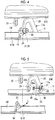
Fig. 4 is a perspective view illustrating an attachment portion. -
Fig. 5 is an exploded perspective view illustrating the attachment portion. -
Fig. 6 is a side view illustrating a connecting shaft. -
Fig. 7 is a front view illustrating the connecting shaft. -
Fig. 8 is a longitudinal sectional view illustrating the connecting shaft inserted in a shaft connection hole. -
Fig. 9 is a partially enlarged perspective view illustrating the connecting shaft inserted in the shaft connection hole. - Hereinafter, an
indoor unit 1 for an air conditioner of an embodiment of the present invention will be described in detail with reference to the drawings. - As illustrated in
Figs. 1 ,2 , and3 , theindoor unit 1 for an air conditioner includes ahousing 2 that has a rectangular parallelepiped shape which is long in a direction which becomes a horizontal direction at the time of mounting and an air conditioning unit (main body portion) 3 accommodated inside thehousing 2. Theindoor unit 1 is a device that sucks air A to adjust a temperature and humidity and then discharges the air A through anoutlet 4, thereby performing indoor air conditioning.Flaps 8 that vertically change a blowing direction of the air A are provided in theindoor unit 1 of the embodiment. - In the embodiment, the direction which becomes the horizontal direction at the time of mounting will be referred to as a right-and-left direction, a direction that becomes an up-and-down direction at the time of mounting will be simply referred to as an up-and-down direction, and a direction orthogonal to the right-and-left direction and the up-and-down direction will be referred to as a front-and-back direction. A side that becomes a near side at the time of mounting is the front of the front-and-back direction.
- As illustrated in
Fig. 2 , theair conditioning unit 3 includes aheat exchanger 5, anair blowing fan 6 that is provided to be covered by theheat exchanger 5, afilter 7 provided in a suction port of the air A, theflaps 8 provided in theoutlet 4 of the air A, and a control box 9 (refer toFig. 3 ) that is provided on one end side of the right-and-left direction and controls air conditioning. - The
housing 2 includes afront panel 10 that is disposed on the front side which becomes the near side at the time of mounting, anupper panel 11 that is integrally connected to thefront panel 10 and is disposed on an upper side at the time of mounting, and a housingmain body 12 that forms a space S, which accommodates theair conditioning unit 3 therein, with thefront panel 10 and theupper panel 11. - The
housing 2 has asuction panel 13 that covers thefront panel 10 from the front. - The housing
main body 12 has a pair ofside panels 14 disposed in the right-and-left direction, aback panel 15 that is integrally connected to the pair ofside panels 14 and opposes a mounting surface, and abottom panel 16 that supports the pair ofside panels 14 and theback panel 15 and is disposed on a lower side. - The housing
main body 12 forms the space S that accommodates theair conditioning unit 3 surrounded by the pair ofside panels 14, theback panel 15, and thebottom panel 16. In the housingmain body 12, the space S is open to the front and the upper side. That is, a front opening portion OP1 that penetrates thehousing 2 in the front-and-back direction and an upper opening portion OP2 that penetrates the housing in the up-and-down direction are formed in the housingmain body 12. - The air A is introduced from the upper opening portion OP2 to the space S of the
housing 2. - The
front panel 10 has a grid shape, and is integrally provided with the housingmain body 12 on the front side of the front opening portion OP1. Theupper panel 11 has a grid shape, and is integrally provided with the housingmain body 12 on an upper side of the upper opening portion OP2. - The
suction panel 13 is disposed in front of thefront panel 10 so as to cover the front opening portion OP1 and thefront panel 10. Thesuction panel 13 can open and close the front opening portion OP1 by being detachable with respect to the housingmain body 12. - The
flaps 8 provided on theoutlet 4 are wind direction adjusting plates that change a direction of the air A from theoutlet 4 in the up-and-down direction. Theindoor unit 1 includes twoflaps 8. The twoflaps 8 can be disposed to block theoutlet 4. The twoflaps 8 each can be rotated about an axis O so as to follow the flow of the air A discharged by theair blowing fan 6. - Next, an attachment structure of each of the
flaps 8 will be described. Herein, out of the twoflaps 8, an attachment structure of theflap 8 disposed on the back will be described. Since an attachment structure of theflap 8 disposed on the front, out of the twoflaps 8, is the same as the attachment structure of theflap 8 disposed on the back, description thereof will be omitted. - As illustrated in
Fig. 3 , theflap 8 is connected to thehousing 2 to be rotatable about the axis O extending in the right-and-left direction via a plurality ofattachment portions 17 that are at intervals in the right-and-left direction. In addition, theflap 8 is rotation-driven about the axis O by a drive motor (not illustrated) provided on one end portion side of an axis O direction (right-and-left direction). For this reason, apin 35 extending in the axis O direction is provided on one end portion of theflap 8, and thepin 35 is connected to the drive motor (not illustrated). - As illustrated in
Figs. 4 and 5 , theattachment portion 17 includes aflap side bracket 19 that is integrally provided with a flapmain body 18 of theflap 8, a housing side bracket (supporting portion) 20 provided in thehousing 2, and a connecting shaft (connecting member) 21 that connects theflap side bracket 19 to thehousing side bracket 20. Thereference sign 22 indicates a housing side bracket used in the flap disposed on the front. - The
flap 8 includes the flapmain body 18 that has a plate shape which is long in the right-and-left direction and theflap side bracket 19 provided on the flapmain body 18 at a position corresponding to theattachment portion 17. - The
flap side bracket 19 is integrally formed with onesurface 18f of the flapmain body 18 to extend from thesurface 18f of the flapmain body 18 in a direction orthogonal to the surface. Theflap side bracket 19 has a plate shape, and has a main surface formed to be orthogonal to the axis O. - A shape of the
flap side bracket 19 seen from the axis O direction is a triangular shape. A rectangular shaft engagement hole 23 (refer toFig. 5 ) that penetrates the flap side bracket in the axis O direction is formed in theflap side bracket 19. - The
housing side bracket 20 has a plate shape, and has a main surface orthogonal to the axis O direction which is formed such that the flow of the air A blown from theoutlet 4 is not obstructed. A shaft insertion hole (through-hole) 24 that penetrates the housing side bracket in the axis O direction is formed in thehousing side bracket 20. For example, theshaft insertion hole 24 has a circular shape. - In a state where one
end 25a side of a shaftmain body 25 of the connectingshaft 21 is inserted in theshaft insertion hole 24 formed in thehousing side bracket 20, anengagement claw portion 26 is engaged with theshaft engagement hole 23 of theflap side bracket 19. - The shaft
main body 25 has a cylindrical shape having a central axis, that is, the axis O as a center thereof. As illustrated inFig. 6 , the shaftmain body 25 has an insertionmain body portion 27 having an outer diameter smaller than an inner diameter of theshaft insertion hole 24 and an increaseddiameter portion 30 having an outer diameter larger than the inner diameter of theshaft insertion hole 24. - The insertion
main body portion 27 has a disk-like shape having a main surface formed to be orthogonal to the central axis (axis O) of the shaftmain body 25 on the oneend 25a side of the shaftmain body 25. That is, the insertionmain body portion 27 blocks the oneend 25a of the increaseddiameter portion 30. - The increased
diameter portion 30 has a cylindrical shape of which a diameter increases as going from the oneend 25a side to theother end 25b side with the insertionmain body portion 27 as a base portion. The increaseddiameter portion 30 has aflange portion 44, which protrudes radially outwards and is formed on theother end 25b of the shaftmain body 25. Theflange portion 44 has the largest outer diameter in the shaftmain body 25. An outer diameter of theflange portion 44 is larger than theshaft insertion hole 24, and the flange portion retains the connectingshaft 21. - Two
slits 28 are formed in a circumferential direction in the increaseddiameter portion 30. Theslits 28 extend up to the insertionmain body portion 27 from theother end 25b toward the oneend 25a side of the shaftmain body 25 in the central axis (axis O) direction of the shaftmain body 25. Due to theslits 28, anupper claw portion 29a on the upper side and alower claw portion 29b on the lower side are formed in the increaseddiameter portion 30. - The
upper claw portion 29a and thelower claw portion 29b extend from the insertionmain body portion 27 toward theother end 25b side. That is, each of theupper claw portion 29a and thelower claw portion 29b has a cantilever shape having the insertionmain body portion 27 as a fixed end and a tip portion on theother end 25b side as a free end. - As illustrated in
Fig. 7 , thelower claw portion 29b has a semicircular arc outline formed over substantially 180° in a case of being seen from the front. An outer circumferential surface of thelower claw portion 29b (excluding the flange portion 44) has a tapered shape such that a diameter increases, and a curvature radius at any position in the axis direction substantially matches a curvature radius of theshaft insertion hole 24. Therefore, when the connectingshaft 21 is inserted in theshaft insertion hole 24 as inFig. 8 , the entire outer circumferential surface of thelower claw portion 29b is in contact with and coincides with an inner circumferential surface of theshaft insertion hole 24. - In a case where the
lower claw portion 29b is fixed to theflap side bracket 19 as inFig. 9 and theflap 8 is positioned at a neutral position in a rotation direction, a middle position of thelower claw portion 29b in the circumferential direction is set to be positioned on a vertical line VL passing through the axis O (refer toFig. 7 ). Accordingly, thelower claw portion 29b is in contact with an inner circumference of theshaft insertion hole 24 over an angle range of ±90° from the middle position of thelower claw portion 29b. - The
upper claw portion 29a has an arc outline formed over an angle range smaller than substantially 180° in a case of being seen from the front. An outer circumferential surface of theupper claw portion 29a (excluding the flange portion 44) has a tapered shape such that a diameter increases. In a case where theupper claw portion 29a and thelower claw portion 29b are seen from the front as inFig. 7 , a radius R1 of theupper claw portion 29a is larger than a radius R2 of thelower claw portion 29b (R1 > R2). In addition, thelower claw portion 29b has rigidity higher than theupper claw portion 29a. Specifically, since an arc length of an appearance of thelower claw portion 29b is larger than an arc length of an appearance of theupper claw portion 29a, the rigidity of thelower claw portion 29b is higher. In addition, a thickness (radial thickness) of thelower claw portion 29b may be larger than a thickness of theupper claw portion 29a. - Therefore, when the connecting
shaft 21 is inserted into theshaft insertion hole 24, theupper claw portion 29a deforms (bends) to an axis O side, and thelower claw portion 29b barely bends. Since thelower claw portion 29b barely deforms as described above, the entire outer circumferential surface of thelower claw portion 29b comes into contact with the inner circumferential surface of theshaft insertion hole 24. Even when theflap 8 rotates about theshaft insertion hole 24 and a load position changes due to the weight of theflap 8, thelower claw portion 29b barely deforms due to rigidity. Thus, a state where the entire outer circumferential surface of thelower claw portion 29b coincides with the inner circumferential surface of theshaft insertion hole 24 is maintained. - In the aforementioned
indoor unit 1, the following operation effects can be achieved. - The
lower claw portion 29b and theupper claw portion 29a of the connectingshaft 21 are inserted into theshaft insertion hole 24, and are attached such that the lower claw portion and the upper claw portion come into contact with the inner circumference of theshaft insertion hole 24. While thelower claw portion 29b receives a load caused by the weight of theflap 8 positioned on the lower side, theupper claw portion 29a does not receive the load caused by the weight of theflap 8. Thus, the rigidity of thelower claw portion 29b is made higher than theupper claw portion 29a such that a deformed amount of thelower claw portion 29b receiving the load of theflap 8 is made as small as possible. Accordingly, even when theflap 8 rotates about the axis O of theshaft insertion hole 24 with the connectingshaft 21, thelower claw portion 29b receives the load of theflap 8. Thus, a strange noise and rattling caused by the deformation of theclaw portions shaft 21 can be reduced. - The radius R1 from the axis O, which is a rotation center of the connecting
shaft 21, to the outer circumferential surface of theupper claw portion 29a is larger than the radius R2 from the axis O, which is the rotation center of the connectingshaft 21, to the outer circumferential surface of thelower claw portion 29b. Accordingly, by actively deforming (bending) theupper claw portion 29a instead of thelower claw portion 29b, the connecting shaft can be suitably brought into contact with the inner circumferential surface of theshaft insertion hole 24 of thehousing side bracket 20. - By making the outer circumferential surface of the
lower claw portion 29b a substantially cylindrical surface formed over substantially 180°, a neutral position of theflap 8 in a rotation range is set to the middle of thelower claw portion 29b. Accordingly, a strange noise and rattling in thelower claw portion 29b can be reduced over the rotation range of substantially 180°, and the load of theflap 8 can be received. -
- 1:
- indoor unit
- 2:
- housing
- 3:
- air conditioning unit (main body portion)
- 4:
- outlet
- 5:
- heat exchanger
- 6:
- air blowing fan
- 7:
- filter
- 8:
- flap
- 9:
- control box
- 10:
- front panel
- 11:
- upper panel
- 12:
- housing main body
- 13:
- suction panel
- 14:
- side panel
- 15:
- back panel
- 16:
- bottom panel
- 17:
- attachment portion
- 18:
- flap main body
- 18f:
- surface
- 19:
- flap side bracket
- 20:
- housing side bracket (supporting portion)
- 21:
- connecting shaft (connecting member)
- 23:
- shaft engagement hole
- 24:
- shaft insertion hole (through-hole)
- 25:
- shaft main body
- 25a:
- one end
- 25b:
- the other end
- 26:
- engagement claw portion
- 27:
- insertion main body portion
- 28:
- slit
- 29a:
- upper claw portion
- 29b:
- lower claw portion
- 30:
- increased diameter portion
- 35:
- pin
- 44:
- flange portion
- A:
- air
- O:
- axis
- OP1:
- front opening portion
- OP2:
- upper opening portion
- R1, R2:
- radius
- S:
- space
- VL:
- vertical line
Claims (3)
- An indoor unit of an air conditioner, comprising:a flap that changes a wind direction;a supporting portion that supports the flap positioned on a lower side with respect to a main body portion; anda connecting member that is fixed to the flap, and is inserted into a through-hole formed in the supporting portion to rotate the flap in the through-hole,wherein the connecting member has a lower claw portion and an upper claw portion that are inserted into the through-hole and each have an outer circumference coming into contact with an inner circumference of the through-hole, andthe lower claw portion has rigidity higher than the upper claw portion.
- The indoor unit of an air conditioner according to Claim 1,
wherein a distance from a rotation center of the connecting member to an outer circumferential surface of the upper claw portion is longer than a distance from the rotation center to the outer circumferential surface of the lower claw portion. - The indoor unit of an air conditioner according to Claim 1 or 2,
wherein the outer circumferential surface of the lower claw portion is a substantially cylindrical surface formed over substantially 180°.
Applications Claiming Priority (2)
| Application Number | Priority Date | Filing Date | Title |
|---|---|---|---|
| JP2017092342A JP6991735B2 (en) | 2017-05-08 | 2017-05-08 | Indoor unit of air conditioner |
| PCT/JP2018/015391 WO2018207544A1 (en) | 2017-05-08 | 2018-04-12 | Indoor unit of air conditioner |
Publications (2)
| Publication Number | Publication Date |
|---|---|
| EP3527906A1 true EP3527906A1 (en) | 2019-08-21 |
| EP3527906A4 EP3527906A4 (en) | 2019-10-30 |
Family
ID=64105565
Family Applications (1)
| Application Number | Title | Priority Date | Filing Date |
|---|---|---|---|
| EP18798858.9A Withdrawn EP3527906A4 (en) | 2017-05-08 | 2018-04-12 | Indoor unit of air conditioner |
Country Status (4)
| Country | Link |
|---|---|
| EP (1) | EP3527906A4 (en) |
| JP (1) | JP6991735B2 (en) |
| AU (1) | AU2018266025B2 (en) |
| WO (1) | WO2018207544A1 (en) |
Cited By (1)
| Publication number | Priority date | Publication date | Assignee | Title |
|---|---|---|---|---|
| CN111365765A (en) * | 2020-04-09 | 2020-07-03 | 海信(广东)空调有限公司 | Air conditioner indoor unit |
Families Citing this family (1)
| Publication number | Priority date | Publication date | Assignee | Title |
|---|---|---|---|---|
| CN112013463B (en) * | 2019-05-31 | 2024-06-21 | 宁波奥克斯电气股份有限公司 | Installation structure and installation method of air outlet correction device |
Family Cites Families (8)
| Publication number | Priority date | Publication date | Assignee | Title |
|---|---|---|---|---|
| JPH06109321A (en) * | 1992-09-29 | 1994-04-19 | Matsushita Electric Ind Co Ltd | Wind deflector for air conditioner |
| JP5980168B2 (en) | 2013-05-29 | 2016-08-31 | 三菱電機株式会社 | Air conditioner indoor unit |
| CN203396058U (en) | 2013-07-11 | 2014-01-15 | 海尔集团公司 | Air deflector connecting shaft for air-conditioning indoor machine and air-conditioning indoor machine |
| CN203928325U (en) * | 2014-06-25 | 2014-11-05 | 广东美的制冷设备有限公司 | Air guide plate connecting shaft sleeve and air-conditioner |
| WO2015192626A1 (en) * | 2014-06-18 | 2015-12-23 | 广东美的制冷设备有限公司 | Connecting member for installing air deflector of air conditioner, air deflector assembly of air conditioner, indoor unit of air conditioner, and air conditioner system |
| JP2016205666A (en) | 2015-04-17 | 2016-12-08 | 三菱重工業株式会社 | Air conditioner |
| JP6503602B2 (en) * | 2015-09-08 | 2019-04-24 | 三菱重工サーマルシステムズ株式会社 | Air conditioner |
| JP6592860B2 (en) | 2015-09-08 | 2019-10-23 | 三菱重工サーマルシステムズ株式会社 | Air conditioner |
-
2017
- 2017-05-08 JP JP2017092342A patent/JP6991735B2/en active Active
-
2018
- 2018-04-12 AU AU2018266025A patent/AU2018266025B2/en active Active
- 2018-04-12 WO PCT/JP2018/015391 patent/WO2018207544A1/en not_active Ceased
- 2018-04-12 EP EP18798858.9A patent/EP3527906A4/en not_active Withdrawn
Cited By (1)
| Publication number | Priority date | Publication date | Assignee | Title |
|---|---|---|---|---|
| CN111365765A (en) * | 2020-04-09 | 2020-07-03 | 海信(广东)空调有限公司 | Air conditioner indoor unit |
Also Published As
| Publication number | Publication date |
|---|---|
| WO2018207544A1 (en) | 2018-11-15 |
| AU2018266025B2 (en) | 2020-07-16 |
| JP2018189309A (en) | 2018-11-29 |
| JP6991735B2 (en) | 2022-01-13 |
| EP3527906A4 (en) | 2019-10-30 |
| AU2018266025A1 (en) | 2019-05-23 |
Similar Documents
| Publication | Publication Date | Title |
|---|---|---|
| EP3702185B1 (en) | Air outlet device, air conditioning system, and vehicle | |
| JP6503602B2 (en) | Air conditioner | |
| JP5562443B2 (en) | Circulator | |
| EP3015776A1 (en) | Air conditioner | |
| CN108317613A (en) | Air conditioner and air conditioner | |
| AU2018266025B2 (en) | Indoor unit of air conditioner | |
| CN208671301U (en) | Air conditioner indoor unit and air conditioner | |
| CN109028293A (en) | Air conditioner indoor unit and air conditioner | |
| JP2012052696A (en) | Air conditioner | |
| JP6592860B2 (en) | Air conditioner | |
| KR20210052272A (en) | Air vent assembly | |
| CN115398157B (en) | air purifier | |
| JP5915958B2 (en) | Air diffusion device (diffusion fan) and air conditioner | |
| JP6391839B2 (en) | Air conditioner indoor unit | |
| KR102925435B1 (en) | Air purifier for vehicle | |
| CN208011891U (en) | Cabinet air-conditioner and air conditioner | |
| CN212407084U (en) | Ceiling fan | |
| CN210292239U (en) | Air deflector and air conditioner with same | |
| CN110410861A (en) | Cabinet air-conditioner | |
| CN106595014A (en) | Chassis air outlet structure and vertical air conditioning equipment with same | |
| JP6790239B2 (en) | Indoor unit of air conditioner | |
| CN115727526B (en) | Air conditioner housing assembly and air conditioner | |
| KR0123419Y1 (en) | Louvre for an airconditioner | |
| CN208671163U (en) | Air conditioner indoor unit and air conditioner | |
| CN107588461A (en) | Water pump assembly and air conditioner with same |
Legal Events
| Date | Code | Title | Description |
|---|---|---|---|
| PUAI | Public reference made under article 153(3) epc to a published international application that has entered the european phase |
Free format text: ORIGINAL CODE: 0009012 |
|
| 17P | Request for examination filed |
Effective date: 20190515 |
|
| AK | Designated contracting states |
Kind code of ref document: A1 Designated state(s): AL AT BE BG CH CY CZ DE DK EE ES FI FR GB GR HR HU IE IS IT LI LT LU LV MC MK MT NL NO PL PT RO RS SE SI SK SM TR |
|
| AX | Request for extension of the european patent |
Extension state: BA ME |
|
| A4 | Supplementary search report drawn up and despatched |
Effective date: 20191002 |
|
| RIC1 | Information provided on ipc code assigned before grant |
Ipc: F24F 130/40 20180101ALN20190926BHEP Ipc: F24F 13/15 20060101ALI20190926BHEP Ipc: F24F 13/14 20060101ALI20190926BHEP Ipc: F24F 1/0011 20190101ALI20190926BHEP Ipc: F24F 13/20 20060101AFI20190926BHEP |
|
| STAA | Information on the status of an ep patent application or granted ep patent |
Free format text: STATUS: THE APPLICATION HAS BEEN WITHDRAWN |
|
| 18W | Application withdrawn |
Effective date: 20191107 |