EP3527905A1 - Indoor unit of air conditioner - Google Patents
Indoor unit of air conditioner Download PDFInfo
- Publication number
- EP3527905A1 EP3527905A1 EP18798502.3A EP18798502A EP3527905A1 EP 3527905 A1 EP3527905 A1 EP 3527905A1 EP 18798502 A EP18798502 A EP 18798502A EP 3527905 A1 EP3527905 A1 EP 3527905A1
- Authority
- EP
- European Patent Office
- Prior art keywords
- connecting member
- stopper
- motor
- indoor unit
- louvers
- Prior art date
- Legal status (The legal status is an assumption and is not a legal conclusion. Google has not performed a legal analysis and makes no representation as to the accuracy of the status listed.)
- Withdrawn
Links
- 230000001105 regulatory effect Effects 0.000 description 3
- 238000004378 air conditioning Methods 0.000 description 2
- 230000000694 effects Effects 0.000 description 2
- 230000006870 function Effects 0.000 description 2
- 238000000034 method Methods 0.000 description 2
- 239000011347 resin Substances 0.000 description 2
- 229920005989 resin Polymers 0.000 description 2
- 230000004044 response Effects 0.000 description 2
- 238000004891 communication Methods 0.000 description 1
- 230000001276 controlling effect Effects 0.000 description 1
- 230000010365 information processing Effects 0.000 description 1
- 230000010355 oscillation Effects 0.000 description 1
- 239000003507 refrigerant Substances 0.000 description 1
- 239000004065 semiconductor Substances 0.000 description 1
Images

Classifications
-
- F—MECHANICAL ENGINEERING; LIGHTING; HEATING; WEAPONS; BLASTING
- F24—HEATING; RANGES; VENTILATING
- F24F—AIR-CONDITIONING; AIR-HUMIDIFICATION; VENTILATION; USE OF AIR CURRENTS FOR SCREENING
- F24F13/00—Details common to, or for air-conditioning, air-humidification, ventilation or use of air currents for screening
- F24F13/08—Air-flow control members, e.g. louvres, grilles, flaps or guide plates
- F24F13/10—Air-flow control members, e.g. louvres, grilles, flaps or guide plates movable, e.g. dampers
- F24F13/14—Air-flow control members, e.g. louvres, grilles, flaps or guide plates movable, e.g. dampers built up of tilting members, e.g. louvre
- F24F13/15—Air-flow control members, e.g. louvres, grilles, flaps or guide plates movable, e.g. dampers built up of tilting members, e.g. louvre with parallel simultaneously tiltable lamellae
-
- F—MECHANICAL ENGINEERING; LIGHTING; HEATING; WEAPONS; BLASTING
- F24—HEATING; RANGES; VENTILATING
- F24F—AIR-CONDITIONING; AIR-HUMIDIFICATION; VENTILATION; USE OF AIR CURRENTS FOR SCREENING
- F24F1/00—Room units for air-conditioning, e.g. separate or self-contained units or units receiving primary air from a central station
- F24F1/0007—Indoor units, e.g. fan coil units
- F24F1/0011—Indoor units, e.g. fan coil units characterised by air outlets
-
- F—MECHANICAL ENGINEERING; LIGHTING; HEATING; WEAPONS; BLASTING
- F24—HEATING; RANGES; VENTILATING
- F24F—AIR-CONDITIONING; AIR-HUMIDIFICATION; VENTILATION; USE OF AIR CURRENTS FOR SCREENING
- F24F13/00—Details common to, or for air-conditioning, air-humidification, ventilation or use of air currents for screening
- F24F13/08—Air-flow control members, e.g. louvres, grilles, flaps or guide plates
- F24F13/10—Air-flow control members, e.g. louvres, grilles, flaps or guide plates movable, e.g. dampers
- F24F13/14—Air-flow control members, e.g. louvres, grilles, flaps or guide plates movable, e.g. dampers built up of tilting members, e.g. louvre
- F24F13/1426—Air-flow control members, e.g. louvres, grilles, flaps or guide plates movable, e.g. dampers built up of tilting members, e.g. louvre characterised by actuating means
-
- F—MECHANICAL ENGINEERING; LIGHTING; HEATING; WEAPONS; BLASTING
- F24—HEATING; RANGES; VENTILATING
- F24F—AIR-CONDITIONING; AIR-HUMIDIFICATION; VENTILATION; USE OF AIR CURRENTS FOR SCREENING
- F24F13/00—Details common to, or for air-conditioning, air-humidification, ventilation or use of air currents for screening
- F24F13/20—Casings or covers
-
- F—MECHANICAL ENGINEERING; LIGHTING; HEATING; WEAPONS; BLASTING
- F24—HEATING; RANGES; VENTILATING
- F24F—AIR-CONDITIONING; AIR-HUMIDIFICATION; VENTILATION; USE OF AIR CURRENTS FOR SCREENING
- F24F13/00—Details common to, or for air-conditioning, air-humidification, ventilation or use of air currents for screening
- F24F13/08—Air-flow control members, e.g. louvres, grilles, flaps or guide plates
- F24F13/10—Air-flow control members, e.g. louvres, grilles, flaps or guide plates movable, e.g. dampers
- F24F13/14—Air-flow control members, e.g. louvres, grilles, flaps or guide plates movable, e.g. dampers built up of tilting members, e.g. louvre
- F24F13/1426—Air-flow control members, e.g. louvres, grilles, flaps or guide plates movable, e.g. dampers built up of tilting members, e.g. louvre characterised by actuating means
- F24F2013/1473—Air-flow control members, e.g. louvres, grilles, flaps or guide plates movable, e.g. dampers built up of tilting members, e.g. louvre characterised by actuating means with cams or levers
Definitions
- the present invention relates to an indoor unit of an air conditioner including a louver that changes a wind direction.
- Louvers for changing a direction of air after air conditioning are provided in an indoor unit of an air conditioner.
- the plurality of louvers are arranged in a predetermined interval in a lateral direction in an outlet of the indoor unit (for example, PTL 1).
- a connecting member to which each louver is rotatably attached is used in order to rotate the plurality of louvers in synchronization.
- the connecting member has a rod shape, and a link member is attached to one end thereof. By a motor oscillating the link member, the connecting member reciprocates in a longitudinal direction, and each louver is rotated, thereby controlling a wind direction.
- the connecting member is made long in order to connect each louver, and thereby dimension management is difficult.
- each louver cannot be lined up to face the front, and thus a problem of the indoor unit looking bad arises.
- an object of the present invention is to provide an indoor unit of an air conditioner that can accurately perform positioning of a plurality of louvers.
- the indoor unit of an air conditioner of the present invention adopts the following means.
- an indoor unit of an air conditioner including a plurality of louvers which are arranged at a predetermined interval in one direction and change a wind direction, a connecting member which extends in the one direction and to which each of the louvers is rotatably attached, a link member which is rotatably attached to the connecting member, a motor which oscillates the link member, a motor bracket which fixes the motor to a main body, and a stopper which is provided in the motor bracket and abuts against the connecting member.
- the stopper that abuts against the connecting member is provided in the motor bracket that fixes the motor to the main body.
- the movement of the connecting member is regulated when the connecting member abuts against the stopper, and thereby positioning of each of the louvers is performed. Since a position is determined by the stopper provided in the motor bracket to which the motor is attached as described above, the positioning of each of the louvers can be accurately performed compared to a case where the stopper is provided in a member different from the motor bracket to which the motor is attached, such as other members including a casing.
- the stopper abuts against the connecting member at a position where the stopper faces the connecting member.
- a control section which controls the motor is further included.
- the control section sets a position where the connecting member has abutted against the stopper as a reference position.
- a reference position of each of the louvers is accurately determined. Accordingly, a rotation angle of each of the louvers can be controlled as a desired position.
- Fig. 1 illustrates an appearance of an indoor unit 1 of an air conditioner.
- the indoor unit 1 is a wall-hanging type, sucks indoor air from above, and blows air after air conditioning indoors from an outlet below.
- the indoor unit 1 is connected to an outdoor unit (not illustrated), receives supply of a refrigerant compressed by the outdoor unit, and adjusts indoor air so as to have a predetermined temperature by means of an indoor heat exchanger provided inside the indoor unit 1.
- Fig. 2 illustrates an inside of the indoor unit 1.
- an indoor heat exchanger 5 is attached to a base plate 3 that is fixed to an indoor wall surface.
- An outlet 7 provided in a width direction of the indoor unit 1 is formed below the indoor heat exchanger 5.
- a plurality of louvers 9 that are at predetermined intervals in the width direction (one direction) are provided in the outlet 7.
- Each of the louvers 9 is a resin plate.
- Each of the louvers 9 is rotatably attached to a bearing portion 11 provided on a main body side of the indoor unit 1.
- An attaching pin 9a (refer to Fig. 3A ) is provided in each of the louvers 9, and the attaching pin 9a is rotatably attached to a connecting member 13.
- the connecting member 13 is made of a resin, and has a rod shape extending in the width direction of the indoor unit 1. A left end, which is one end of the connecting member, is disposed to be positioned on a motor bracket 15 side.
- a motor bracket 15 is fixed to a main body of the indoor unit 1, and accommodates a motor for driving the louvers 9.
- Figs. 3A and 3B are enlarged views of surroundings of the connecting member 13 and the motor bracket 15.
- One end of a link member 17 is rotatably attached to the left end of the connecting member 13.
- the other end of the link member 17 is attached to a motor shaft 19. Therefore, when the motor shaft 19 is rotated by the motor, the link member 17 oscillates, and accordingly the connecting member 13 reciprocates in a substantially longitudinal direction.
- a rotation angle of each of the louvers 9 changes.
- a rotation angle of the motor shaft 19 is transmitted to a control section (not illustrated).
- a stopper 16 is fixed to the motor bracket 15. As illustrated in Figs. 4A and 4B , the stopper 16 regulates the movement of the connecting member 13 by abutting against a tip 13a of the connecting member 13.
- an abutting surface 13b of the tip 13a of the connecting member 13 comes into surface-contact with an abutting surface 16a of the stopper 16. That is, the abutting surface 16a of the stopper 16 is set to face the abutting surface 13b of the connecting member 13.
- the control section sets a position where the tip 13a of the connecting member 13 has abutted against the stopper 16 as a reference position. Then, based on the reference position, the control section controls the rotation angle of the motor shaft 19 and controls a position of each of the louvers 9.
- control section is configured with a central processing unit (CPU), a random access memory (RAM), a read only memory (ROM), a computer readable storage medium, and like.
- CPU central processing unit
- RAM random access memory
- ROM read only memory
- a series of processes for realizing various types of functions are stored in a storage medium or the like in the form of a program, and the program is read by the CPU with the RAM or the like to execute an information processing and computing process, thereby realizing the various types of functions.
- the program may be applied in a form of being installed in advance in the ROM or other storage media, a form of being provided in a state of being stored in the computer readable storage medium, a form of being distributed via communication means in a wired or wireless manner, and the like.
- the computer readable storage medium refers to a magnetic disk, a magneto-optical disk, a CD-ROM, a DVD-ROM, a semiconductor memory, and the like.
- Positioning of a reference position of each of the louvers 9 is performed as follows.
- the motor is driven in accordance with a command from the control section to rotate the motor shaft 19, and thereby the link member 17 oscillates.
- the tip 13a of the connecting member 13 moves to a stopper 16 side, and the abutting surface 13b of the connecting member 13 comes into surface-contact with the abutting surface 16a of the stopper 16.
- the control section sets this position as a reference position. With the reference position as reference, the control section rotates the motor shaft 19 and controls a wind direction angle of each of the louvers 9.
- the stopper 16 that abuts against the connecting member 13 is provided in the motor bracket 15 that fixes the motor to the main body of the indoor unit 1.
- the movement of the connecting member 13 is regulated when the connecting member abuts against the stopper 16, and thereby positioning of each of the louvers 9 is performed. Since a position is determined by the stopper 16 provided in the motor bracket 15 to which the motor is attached as described above, the positioning of each of the louvers 9 can be accurately performed compared to a case where the stopper 16 is provided in a member different from the motor bracket 15 to which the motor is attached, such as other members including a casing.
- the control section setting the position where the stopper 16 has abutted against the connecting member 13 as a reference position, the reference position of each of the louvers 9 is accurately determined. Accordingly, the rotation angle of each of the louvers 9 can be controlled as a desired position.
Landscapes
- Engineering & Computer Science (AREA)
- Chemical & Material Sciences (AREA)
- Combustion & Propulsion (AREA)
- Mechanical Engineering (AREA)
- General Engineering & Computer Science (AREA)
- Air-Flow Control Members (AREA)
- Air Filters, Heat-Exchange Apparatuses, And Housings Of Air-Conditioning Units (AREA)
Abstract
This indoor unit of an air conditioner is provided with: multiple louvers (9) which are arranged at a prescribed interval in the width direction of a blow port and which change the air flow direction; a connecting member (13) which extends in the width direction and to which the louvers (9) are rotatably attached; a ring member (17) which is rotatably attached to the connecting member (13); a motor which pivots the ring member (17); a motor bracket (15) which fixes the motor to the main body; and a stopper (16) which is provided on the motor bracket (15) and contacts the connecting member (13).
Description
- The present invention relates to an indoor unit of an air conditioner including a louver that changes a wind direction.
- Louvers for changing a direction of air after air conditioning are provided in an indoor unit of an air conditioner. The plurality of louvers are arranged in a predetermined interval in a lateral direction in an outlet of the indoor unit (for example, PTL 1).
- [PTL 1] Japanese Unexamined Patent Application Publication No.
11-118186 - A connecting member to which each louver is rotatably attached is used in order to rotate the plurality of louvers in synchronization. The connecting member has a rod shape, and a link member is attached to one end thereof. By a motor oscillating the link member, the connecting member reciprocates in a longitudinal direction, and each louver is rotated, thereby controlling a wind direction.
- However, the connecting member is made long in order to connect each louver, and thereby dimension management is difficult. In addition, when a reference position of the connecting member is not accurately determined, each louver cannot be lined up to face the front, and thus a problem of the indoor unit looking bad arises.
- In view of such circumstances, an object of the present invention is to provide an indoor unit of an air conditioner that can accurately perform positioning of a plurality of louvers.
- In order to solve the problems, the indoor unit of an air conditioner of the present invention adopts the following means.
- That is, according to an aspect of the present invention, there is provided an indoor unit of an air conditioner including a plurality of louvers which are arranged at a predetermined interval in one direction and change a wind direction, a connecting member which extends in the one direction and to which each of the louvers is rotatably attached, a link member which is rotatably attached to the connecting member, a motor which oscillates the link member, a motor bracket which fixes the motor to a main body, and a stopper which is provided in the motor bracket and abuts against the connecting member.
- When the motor oscillates the link member, the connecting member to which the link member is attached moves. When the connecting member moves, each louver attached to the connecting member rotates, and a wind direction changes.
- The stopper that abuts against the connecting member is provided in the motor bracket that fixes the motor to the main body. The movement of the connecting member is regulated when the connecting member abuts against the stopper, and thereby positioning of each of the louvers is performed. Since a position is determined by the stopper provided in the motor bracket to which the motor is attached as described above, the positioning of each of the louvers can be accurately performed compared to a case where the stopper is provided in a member different from the motor bracket to which the motor is attached, such as other members including a casing.
- In the indoor unit of an air conditioner according to the aspect of the present invention, the stopper abuts against the connecting member at a position where the stopper faces the connecting member.
- Since the stopper abuts against the connecting member at the position where the stopper faces the connecting member, a shift of the connecting member can be suppressed after the connecting member has abutted against the stopper. Accordingly, more accurate positioning of the louvers can be performed.
- In the indoor unit of an air conditioner according to the aspect of the present invention, a control section which controls the motor is further included. The control section sets a position where the connecting member has abutted against the stopper as a reference position.
- By the control section setting the position where the stopper has abutted against the connecting member as the reference position, a reference position of each of the louvers is accurately determined. Accordingly, a rotation angle of each of the louvers can be controlled as a desired position.
- Since a position is determined by the stopper provided in the motor bracket to which the motor is attached, the positioning of the plurality of louvers can be accurately performed.
-
-
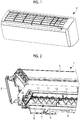
Fig. 1 is a perspective view illustrating an indoor unit of an air conditioner according to an embodiment of the present invention. -
Fig. 2 is a perspective view illustrating an inside of the indoor unit ofFig. 1 . -
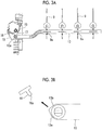
Fig. 3A is a plan view illustrating a state where a connecting member is separated away from a stopper. -
Fig. 3B is a partially enlarged plan view ofFig. 3A . -
Fig. 4A is a plan view illustrating a state where the connecting member has abutted against the stopper. -
Fig. 4B is a partially enlarged plan view ofFig. 4A . - Hereinafter, an embodiment according to the present invention will be described with reference to the drawings.
-
Fig. 1 illustrates an appearance of an indoor unit 1 of an air conditioner. The indoor unit 1 is a wall-hanging type, sucks indoor air from above, and blows air after air conditioning indoors from an outlet below. The indoor unit 1 is connected to an outdoor unit (not illustrated), receives supply of a refrigerant compressed by the outdoor unit, and adjusts indoor air so as to have a predetermined temperature by means of an indoor heat exchanger provided inside the indoor unit 1. -
Fig. 2 illustrates an inside of the indoor unit 1. As illustrated inFig. 2 , an indoor heat exchanger 5 is attached to abase plate 3 that is fixed to an indoor wall surface. An outlet 7 provided in a width direction of the indoor unit 1 is formed below the indoor heat exchanger 5. A plurality oflouvers 9 that are at predetermined intervals in the width direction (one direction) are provided in the outlet 7. Each of thelouvers 9 is a resin plate. Each of thelouvers 9 is rotatably attached to abearing portion 11 provided on a main body side of the indoor unit 1. An attachingpin 9a (refer toFig. 3A ) is provided in each of thelouvers 9, and the attachingpin 9a is rotatably attached to a connectingmember 13. - The connecting
member 13 is made of a resin, and has a rod shape extending in the width direction of the indoor unit 1. A left end, which is one end of the connecting member, is disposed to be positioned on amotor bracket 15 side. - A
motor bracket 15 is fixed to a main body of the indoor unit 1, and accommodates a motor for driving thelouvers 9. -
Figs. 3A and 3B are enlarged views of surroundings of the connectingmember 13 and themotor bracket 15. One end of alink member 17 is rotatably attached to the left end of the connectingmember 13. The other end of thelink member 17 is attached to amotor shaft 19. Therefore, when themotor shaft 19 is rotated by the motor, thelink member 17 oscillates, and accordingly the connectingmember 13 reciprocates in a substantially longitudinal direction. In response to the reciprocation of the connectingmember 13, a rotation angle of each of thelouvers 9 changes. A rotation angle of themotor shaft 19 is transmitted to a control section (not illustrated). - A
stopper 16 is fixed to themotor bracket 15. As illustrated inFigs. 4A and 4B , thestopper 16 regulates the movement of the connectingmember 13 by abutting against atip 13a of the connectingmember 13. - As seen from
Figs. 3B and4B , an abuttingsurface 13b of thetip 13a of the connectingmember 13 comes into surface-contact with anabutting surface 16a of thestopper 16. That is, the abuttingsurface 16a of thestopper 16 is set to face theabutting surface 13b of the connectingmember 13. - The control section sets a position where the
tip 13a of the connectingmember 13 has abutted against thestopper 16 as a reference position. Then, based on the reference position, the control section controls the rotation angle of themotor shaft 19 and controls a position of each of thelouvers 9. - For example, the control section is configured with a central processing unit (CPU), a random access memory (RAM), a read only memory (ROM), a computer readable storage medium, and like. For example, a series of processes for realizing various types of functions are stored in a storage medium or the like in the form of a program, and the program is read by the CPU with the RAM or the like to execute an information processing and computing process, thereby realizing the various types of functions. The program may be applied in a form of being installed in advance in the ROM or other storage media, a form of being provided in a state of being stored in the computer readable storage medium, a form of being distributed via communication means in a wired or wireless manner, and the like. The computer readable storage medium refers to a magnetic disk, a magneto-optical disk, a CD-ROM, a DVD-ROM, a semiconductor memory, and the like.
- Positioning of a reference position of each of the
louvers 9 is performed as follows. - First, the motor is driven in accordance with a command from the control section to rotate the
motor shaft 19, and thereby thelink member 17 oscillates. In response to the oscillation of thelink member 17, thetip 13a of the connectingmember 13 moves to astopper 16 side, and theabutting surface 13b of the connectingmember 13 comes into surface-contact with theabutting surface 16a of thestopper 16. Accordingly, the movement of the connectingmember 13 is regulated, and the control section sets this position as a reference position. With the reference position as reference, the control section rotates themotor shaft 19 and controls a wind direction angle of each of thelouvers 9. - In the aforementioned indoor unit 1, the following operation effects can be achieved.
- The
stopper 16 that abuts against the connectingmember 13 is provided in themotor bracket 15 that fixes the motor to the main body of the indoor unit 1. The movement of the connectingmember 13 is regulated when the connecting member abuts against thestopper 16, and thereby positioning of each of thelouvers 9 is performed. Since a position is determined by thestopper 16 provided in themotor bracket 15 to which the motor is attached as described above, the positioning of each of thelouvers 9 can be accurately performed compared to a case where thestopper 16 is provided in a member different from themotor bracket 15 to which the motor is attached, such as other members including a casing. - Since the
stopper 16 abuts against and comes into surface-contact with the connectingmember 13 at a position where the stopper faces the connecting member, strong frictional forces act. Thus, after the connectingmember 13 has abutted against thestopper 16, a shift of the connectingmember 13 can be suppressed. Accordingly, more accurate positioning of thelouvers 9 can be performed. - By the control section setting the position where the
stopper 16 has abutted against the connectingmember 13 as a reference position, the reference position of each of thelouvers 9 is accurately determined. Accordingly, the rotation angle of each of thelouvers 9 can be controlled as a desired position. -
- 1: indoor unit
- 3: base plate
- 5: indoor heat exchanger
- 7: outlet
- 9: louver
- 11: bearing portion
- 13: connecting member
- 13a: tip
- 13b: abutting surface
- 15: motor bracket
- 16: stopper
- 16a: abutting surface
- 17: link member
- 19: motor shaft
Claims (3)
- An indoor unit of an air conditioner, comprising:a plurality of louvers which are arranged at a predetermined interval in one direction and change a wind direction;a connecting member which extends in the one direction and to which each of the louvers is rotatably attached;a link member which is rotatably attached to the connecting member;a motor which oscillates the link member;a motor bracket which fixes the motor to a main body; anda stopper which is provided in the motor bracket and abuts against the connecting member.
- The indoor unit of an air conditioner according to Claim 1,
wherein the stopper abuts against the connecting member at a position where the stopper faces the connecting member. - The indoor unit of an air conditioner according to Claim 1 or 2, further comprising:a control section which controls the motor,wherein the control section sets a position where the connecting member has abutted against the stopper as a reference position.
Applications Claiming Priority (2)
| Application Number | Priority Date | Filing Date | Title |
|---|---|---|---|
| JP2017092343A JP6938208B2 (en) | 2017-05-08 | 2017-05-08 | Indoor unit of air conditioner |
| PCT/JP2018/015599 WO2018207554A1 (en) | 2017-05-08 | 2018-04-13 | Indoor unit of air conditioner |
Publications (1)
| Publication Number | Publication Date |
|---|---|
| EP3527905A1 true EP3527905A1 (en) | 2019-08-21 |
Family
ID=64104533
Family Applications (1)
| Application Number | Title | Priority Date | Filing Date |
|---|---|---|---|
| EP18798502.3A Withdrawn EP3527905A1 (en) | 2017-05-08 | 2018-04-13 | Indoor unit of air conditioner |
Country Status (4)
| Country | Link |
|---|---|
| EP (1) | EP3527905A1 (en) |
| JP (1) | JP6938208B2 (en) |
| AU (1) | AU2018266035B2 (en) |
| WO (1) | WO2018207554A1 (en) |
Family Cites Families (12)
| Publication number | Priority date | Publication date | Assignee | Title |
|---|---|---|---|---|
| JPS61265441A (en) * | 1985-05-20 | 1986-11-25 | Matsushita Electric Ind Co Ltd | flow direction control device |
| JPH0715335B2 (en) * | 1989-02-28 | 1995-02-22 | 大協株式会社 | Air conditioning outlet device |
| KR0125731B1 (en) * | 1992-06-10 | 1998-04-01 | 강진구 | Wind direction control device of heating equipment |
| JPH10103751A (en) * | 1996-09-30 | 1998-04-21 | Toshiba Corp | Air conditioner indoor unit |
| JPH11118186A (en) | 1997-10-20 | 1999-04-30 | Fujitsu General Ltd | Air conditioner |
| JP2000168351A (en) * | 1998-12-07 | 2000-06-20 | Kojima Press Co Ltd | Air outlet device for vehicle |
| JP2002243263A (en) * | 2001-02-20 | 2002-08-28 | Fujitsu General Ltd | Air conditioner |
| KR100857319B1 (en) * | 2003-04-30 | 2008-09-05 | 엘지전자 주식회사 | Opening and closing detection device and method of louver blade for outdoor unit |
| JP5419428B2 (en) * | 2008-11-20 | 2014-02-19 | 三菱重工業株式会社 | Air conditioner |
| JP5664644B2 (en) * | 2012-12-28 | 2015-02-04 | 株式会社富士通ゼネラル | Air conditioner and control circuit |
| JP6066783B2 (en) * | 2013-03-07 | 2017-01-25 | 三菱電機株式会社 | Air conditioner indoor unit and air conditioner equipped with the same |
| JP6275626B2 (en) * | 2014-11-14 | 2018-02-07 | 象印マホービン株式会社 | Blower |
-
2017
- 2017-05-08 JP JP2017092343A patent/JP6938208B2/en active Active
-
2018
- 2018-04-13 AU AU2018266035A patent/AU2018266035B2/en active Active
- 2018-04-13 EP EP18798502.3A patent/EP3527905A1/en not_active Withdrawn
- 2018-04-13 WO PCT/JP2018/015599 patent/WO2018207554A1/en not_active Ceased
Also Published As
| Publication number | Publication date |
|---|---|
| JP6938208B2 (en) | 2021-09-22 |
| JP2018189310A (en) | 2018-11-29 |
| AU2018266035A1 (en) | 2019-05-23 |
| AU2018266035B2 (en) | 2020-06-04 |
| WO2018207554A1 (en) | 2018-11-15 |
Similar Documents
| Publication | Publication Date | Title |
|---|---|---|
| AU2005206673B2 (en) | Ceiling Embedded Type Air Conditioner, and a Control Method Thereof | |
| JP6213539B2 (en) | Indoor unit of air conditioner | |
| CN204629732U (en) | Air conditioner room unit and the air-conditioner with it | |
| CN106090384A (en) | Motor operated valve and electric valve control device | |
| CN204460625U (en) | Indoor set and air conditioner | |
| CN105258304A (en) | Low-temperature refrigeration control method, low-temperature refrigeration control device and air conditioner | |
| AU2018266035B2 (en) | Indoor unit of air conditioner | |
| JP6184592B2 (en) | Air conditioner and air conditioning system | |
| CN109945563B (en) | Multi-split air conditioning system and method and device for initializing electronic expansion valve thereof | |
| EP3722692A1 (en) | Indoor unit for air conditioner | |
| KR100936785B1 (en) | Automatic Swirl Diffuser for Air Conditioners | |
| CN206347709U (en) | Indoor unit and air conditioner | |
| EP3543620A1 (en) | Drain hose fastener, and indoor unit for air conditioning device | |
| CN208765230U (en) | Ceiling embedded indoor unit and air conditioner of air conditioner | |
| CN206648389U (en) | Refrigerator puts wind structure and refrigerator | |
| EP3447395A1 (en) | Technique for heat transfer using air flow | |
| WO2023098781A1 (en) | System and method for adjusting control settings of electrical appliance | |
| JP5506579B2 (en) | Air conditioner indoor unit | |
| CN114222892B (en) | Blowout grill and indoor unit of air conditioner using same | |
| CN204718084U (en) | The installing plate assembly of wall-hanging air conditioner | |
| JP2008138957A (en) | Wind direction changing device and air conditioner having the same | |
| CN201731596U (en) | Air-conditioner | |
| US20260036328A1 (en) | Pattern controller for diffuser | |
| JPH0387550A (en) | Heat pump type air conditioner | |
| JP6811876B2 (en) | Indoor unit and air conditioner |
Legal Events
| Date | Code | Title | Description |
|---|---|---|---|
| PUAI | Public reference made under article 153(3) epc to a published international application that has entered the european phase |
Free format text: ORIGINAL CODE: 0009012 |
|
| 17P | Request for examination filed |
Effective date: 20190515 |
|
| AK | Designated contracting states |
Kind code of ref document: A1 Designated state(s): AL AT BE BG CH CY CZ DE DK EE ES FI FR GB GR HR HU IE IS IT LI LT LU LV MC MK MT NL NO PL PT RO RS SE SI SK SM TR |
|
| AX | Request for extension of the european patent |
Extension state: BA ME |
|
| STAA | Information on the status of an ep patent application or granted ep patent |
Free format text: STATUS: THE APPLICATION HAS BEEN WITHDRAWN |
|
| 18W | Application withdrawn |
Effective date: 20191107 |