EP3527850A1 - Drive source control device, and vehicle equipped with said drive source control device - Google Patents
Drive source control device, and vehicle equipped with said drive source control device Download PDFInfo
- Publication number
- EP3527850A1 EP3527850A1 EP17859488.3A EP17859488A EP3527850A1 EP 3527850 A1 EP3527850 A1 EP 3527850A1 EP 17859488 A EP17859488 A EP 17859488A EP 3527850 A1 EP3527850 A1 EP 3527850A1
- Authority
- EP
- European Patent Office
- Prior art keywords
- torque
- drive
- rotation speed
- drive source
- overspeed
- Prior art date
- Legal status (The legal status is an assumption and is not a legal conclusion. Google has not performed a legal analysis and makes no representation as to the accuracy of the status listed.)
- Granted
Links
Images




Classifications
-
- B—PERFORMING OPERATIONS; TRANSPORTING
- B60—VEHICLES IN GENERAL
- B60L—PROPULSION OF ELECTRICALLY-PROPELLED VEHICLES; SUPPLYING ELECTRIC POWER FOR AUXILIARY EQUIPMENT OF ELECTRICALLY-PROPELLED VEHICLES; ELECTRODYNAMIC BRAKE SYSTEMS FOR VEHICLES IN GENERAL; MAGNETIC SUSPENSION OR LEVITATION FOR VEHICLES; MONITORING OPERATING VARIABLES OF ELECTRICALLY-PROPELLED VEHICLES; ELECTRIC SAFETY DEVICES FOR ELECTRICALLY-PROPELLED VEHICLES
- B60L15/00—Methods, circuits, or devices for controlling the traction-motor speed of electrically-propelled vehicles
- B60L15/20—Methods, circuits, or devices for controlling the traction-motor speed of electrically-propelled vehicles for control of the vehicle or its driving motor to achieve a desired performance, e.g. speed, torque, programmed variation of speed
- B60L15/2036—Electric differentials, e.g. for supporting steering vehicles
-
- B—PERFORMING OPERATIONS; TRANSPORTING
- B60—VEHICLES IN GENERAL
- B60L—PROPULSION OF ELECTRICALLY-PROPELLED VEHICLES; SUPPLYING ELECTRIC POWER FOR AUXILIARY EQUIPMENT OF ELECTRICALLY-PROPELLED VEHICLES; ELECTRODYNAMIC BRAKE SYSTEMS FOR VEHICLES IN GENERAL; MAGNETIC SUSPENSION OR LEVITATION FOR VEHICLES; MONITORING OPERATING VARIABLES OF ELECTRICALLY-PROPELLED VEHICLES; ELECTRIC SAFETY DEVICES FOR ELECTRICALLY-PROPELLED VEHICLES
- B60L15/00—Methods, circuits, or devices for controlling the traction-motor speed of electrically-propelled vehicles
- B60L15/20—Methods, circuits, or devices for controlling the traction-motor speed of electrically-propelled vehicles for control of the vehicle or its driving motor to achieve a desired performance, e.g. speed, torque, programmed variation of speed
-
- B—PERFORMING OPERATIONS; TRANSPORTING
- B60—VEHICLES IN GENERAL
- B60L—PROPULSION OF ELECTRICALLY-PROPELLED VEHICLES; SUPPLYING ELECTRIC POWER FOR AUXILIARY EQUIPMENT OF ELECTRICALLY-PROPELLED VEHICLES; ELECTRODYNAMIC BRAKE SYSTEMS FOR VEHICLES IN GENERAL; MAGNETIC SUSPENSION OR LEVITATION FOR VEHICLES; MONITORING OPERATING VARIABLES OF ELECTRICALLY-PROPELLED VEHICLES; ELECTRIC SAFETY DEVICES FOR ELECTRICALLY-PROPELLED VEHICLES
- B60L15/00—Methods, circuits, or devices for controlling the traction-motor speed of electrically-propelled vehicles
- B60L15/20—Methods, circuits, or devices for controlling the traction-motor speed of electrically-propelled vehicles for control of the vehicle or its driving motor to achieve a desired performance, e.g. speed, torque, programmed variation of speed
- B60L15/2009—Methods, circuits, or devices for controlling the traction-motor speed of electrically-propelled vehicles for control of the vehicle or its driving motor to achieve a desired performance, e.g. speed, torque, programmed variation of speed for braking
-
- F—MECHANICAL ENGINEERING; LIGHTING; HEATING; WEAPONS; BLASTING
- F16—ENGINEERING ELEMENTS AND UNITS; GENERAL MEASURES FOR PRODUCING AND MAINTAINING EFFECTIVE FUNCTIONING OF MACHINES OR INSTALLATIONS; THERMAL INSULATION IN GENERAL
- F16H—GEARING
- F16H48/00—Differential gearings
- F16H48/36—Differential gearings characterised by intentionally generating speed difference between outputs
-
- B—PERFORMING OPERATIONS; TRANSPORTING
- B60—VEHICLES IN GENERAL
- B60L—PROPULSION OF ELECTRICALLY-PROPELLED VEHICLES; SUPPLYING ELECTRIC POWER FOR AUXILIARY EQUIPMENT OF ELECTRICALLY-PROPELLED VEHICLES; ELECTRODYNAMIC BRAKE SYSTEMS FOR VEHICLES IN GENERAL; MAGNETIC SUSPENSION OR LEVITATION FOR VEHICLES; MONITORING OPERATING VARIABLES OF ELECTRICALLY-PROPELLED VEHICLES; ELECTRIC SAFETY DEVICES FOR ELECTRICALLY-PROPELLED VEHICLES
- B60L2220/00—Electrical machine types; Structures or applications thereof
- B60L2220/40—Electrical machine applications
- B60L2220/42—Electrical machine applications with use of more than one motor
-
- B—PERFORMING OPERATIONS; TRANSPORTING
- B60—VEHICLES IN GENERAL
- B60L—PROPULSION OF ELECTRICALLY-PROPELLED VEHICLES; SUPPLYING ELECTRIC POWER FOR AUXILIARY EQUIPMENT OF ELECTRICALLY-PROPELLED VEHICLES; ELECTRODYNAMIC BRAKE SYSTEMS FOR VEHICLES IN GENERAL; MAGNETIC SUSPENSION OR LEVITATION FOR VEHICLES; MONITORING OPERATING VARIABLES OF ELECTRICALLY-PROPELLED VEHICLES; ELECTRIC SAFETY DEVICES FOR ELECTRICALLY-PROPELLED VEHICLES
- B60L2240/00—Control parameters of input or output; Target parameters
- B60L2240/40—Drive Train control parameters
- B60L2240/42—Drive Train control parameters related to electric machines
- B60L2240/421—Speed
-
- B—PERFORMING OPERATIONS; TRANSPORTING
- B60—VEHICLES IN GENERAL
- B60L—PROPULSION OF ELECTRICALLY-PROPELLED VEHICLES; SUPPLYING ELECTRIC POWER FOR AUXILIARY EQUIPMENT OF ELECTRICALLY-PROPELLED VEHICLES; ELECTRODYNAMIC BRAKE SYSTEMS FOR VEHICLES IN GENERAL; MAGNETIC SUSPENSION OR LEVITATION FOR VEHICLES; MONITORING OPERATING VARIABLES OF ELECTRICALLY-PROPELLED VEHICLES; ELECTRIC SAFETY DEVICES FOR ELECTRICALLY-PROPELLED VEHICLES
- B60L2240/00—Control parameters of input or output; Target parameters
- B60L2240/40—Drive Train control parameters
- B60L2240/42—Drive Train control parameters related to electric machines
- B60L2240/423—Torque
-
- B—PERFORMING OPERATIONS; TRANSPORTING
- B60—VEHICLES IN GENERAL
- B60L—PROPULSION OF ELECTRICALLY-PROPELLED VEHICLES; SUPPLYING ELECTRIC POWER FOR AUXILIARY EQUIPMENT OF ELECTRICALLY-PROPELLED VEHICLES; ELECTRODYNAMIC BRAKE SYSTEMS FOR VEHICLES IN GENERAL; MAGNETIC SUSPENSION OR LEVITATION FOR VEHICLES; MONITORING OPERATING VARIABLES OF ELECTRICALLY-PROPELLED VEHICLES; ELECTRIC SAFETY DEVICES FOR ELECTRICALLY-PROPELLED VEHICLES
- B60L2240/00—Control parameters of input or output; Target parameters
- B60L2240/40—Drive Train control parameters
- B60L2240/46—Drive Train control parameters related to wheels
- B60L2240/461—Speed
-
- B—PERFORMING OPERATIONS; TRANSPORTING
- B60—VEHICLES IN GENERAL
- B60L—PROPULSION OF ELECTRICALLY-PROPELLED VEHICLES; SUPPLYING ELECTRIC POWER FOR AUXILIARY EQUIPMENT OF ELECTRICALLY-PROPELLED VEHICLES; ELECTRODYNAMIC BRAKE SYSTEMS FOR VEHICLES IN GENERAL; MAGNETIC SUSPENSION OR LEVITATION FOR VEHICLES; MONITORING OPERATING VARIABLES OF ELECTRICALLY-PROPELLED VEHICLES; ELECTRIC SAFETY DEVICES FOR ELECTRICALLY-PROPELLED VEHICLES
- B60L9/00—Electric propulsion with power supply external to the vehicle
- B60L9/16—Electric propulsion with power supply external to the vehicle using AC induction motors
- B60L9/18—Electric propulsion with power supply external to the vehicle using AC induction motors fed from DC supply lines
-
- F—MECHANICAL ENGINEERING; LIGHTING; HEATING; WEAPONS; BLASTING
- F16—ENGINEERING ELEMENTS AND UNITS; GENERAL MEASURES FOR PRODUCING AND MAINTAINING EFFECTIVE FUNCTIONING OF MACHINES OR INSTALLATIONS; THERMAL INSULATION IN GENERAL
- F16H—GEARING
- F16H48/00—Differential gearings
- F16H48/36—Differential gearings characterised by intentionally generating speed difference between outputs
- F16H2048/368—Differential gearings characterised by intentionally generating speed difference between outputs using additional orbital gears in combination with clutches or brakes
-
- Y—GENERAL TAGGING OF NEW TECHNOLOGICAL DEVELOPMENTS; GENERAL TAGGING OF CROSS-SECTIONAL TECHNOLOGIES SPANNING OVER SEVERAL SECTIONS OF THE IPC; TECHNICAL SUBJECTS COVERED BY FORMER USPC CROSS-REFERENCE ART COLLECTIONS [XRACs] AND DIGESTS
- Y02—TECHNOLOGIES OR APPLICATIONS FOR MITIGATION OR ADAPTATION AGAINST CLIMATE CHANGE
- Y02T—CLIMATE CHANGE MITIGATION TECHNOLOGIES RELATED TO TRANSPORTATION
- Y02T10/00—Road transport of goods or passengers
- Y02T10/60—Other road transportation technologies with climate change mitigation effect
- Y02T10/64—Electric machine technologies in electromobility
-
- Y—GENERAL TAGGING OF NEW TECHNOLOGICAL DEVELOPMENTS; GENERAL TAGGING OF CROSS-SECTIONAL TECHNOLOGIES SPANNING OVER SEVERAL SECTIONS OF THE IPC; TECHNICAL SUBJECTS COVERED BY FORMER USPC CROSS-REFERENCE ART COLLECTIONS [XRACs] AND DIGESTS
- Y02—TECHNOLOGIES OR APPLICATIONS FOR MITIGATION OR ADAPTATION AGAINST CLIMATE CHANGE
- Y02T—CLIMATE CHANGE MITIGATION TECHNOLOGIES RELATED TO TRANSPORTATION
- Y02T10/00—Road transport of goods or passengers
- Y02T10/60—Other road transportation technologies with climate change mitigation effect
- Y02T10/72—Electric energy management in electromobility
Definitions
- the present invention relates to: a drive source control device for transmitting driving torques generated from two independent drive sources, to left and right drive wheels, with a torque difference therebetween amplified; and a vehicle equipped with the drive source control device.
- a vehicle driving device in which a gear device having two planetary gear mechanisms combined is provided between two drive sources and left and right drive wheels so as to amplify the torque difference (Patent Documents 1 and 2).
- output torques of the two drive sources are determined and controlled on the basis of torque command values for the left and right drive wheels issued from a high-order ECU.
- the patent documents disclose electric motors as the drive sources.
- Patent Document 3 As a method for coping with the case where the electric motor reaches overspeed, a motor control method for detecting overspeed of a motor of an electric vehicle and preventing damage to the motor is disclosed (Patent Document 3).
- TWL ⁇ 1 + ⁇ / 2 ⁇ TM 1 + ⁇ 1 ⁇ ⁇ / 2 ⁇ TM 2
- TWR ⁇ 1 ⁇ ⁇ / 2 ⁇ TM 1 + ⁇ 1 + ⁇ / 2 ⁇ TM 2
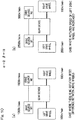
- Fig. 10 shows one example.
- the rotation speeds of the drive source M1 corresponding to the left drive wheel and the drive source M2 corresponding to the right drive wheel are 1000 r/min, as shown in diagram (a) of Fig. 10 .
- the rotation speed of the left drive wheel increases to 200 r/min
- the rotation speed of the drive source M1 increases to 2500 r/min
- the rotation speed of the drive source M2 decreases to 500 r/min, as shown in diagram (b) of Fig. 10 .
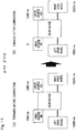
- Fig. 11 shows one example.
- the torques of the left and right drive wheels are 100 N ⁇ m.
- the torque of the drive source M1 is adjusted to zero and the torque of the drive source M2 is maintained at 10 N ⁇ m, the torque of the left drive wheel becomes -50 N ⁇ m and the torque of the right drive wheel becomes 150 N ⁇ m, and thus the torque of the right drive wheel increases.
- the above situation might occur.
- the right drive wheel is on an asphalt road surface and the left drive wheel is on a frozen road surface
- the left drive wheel is likely to spin at the time of starting to move or accelerating
- the drive source M1 has reached overspeed, if the torque TM1 of the drive source M1 is set to zero or in a regeneration direction, the torque of the right drive wheel which is on the asphalt road increases, so that the vehicle turns leftward. As a result, the vehicle attitude might become unstable.
- An object of the present invention is to provide: a drive source control device that can suppress increase in the rotation speed of a drive source and suppress occurrence of an unnecessary yaw moment to stabilize the vehicle attitude; and a vehicle equipped with the drive source control device.
- a drive source control device 67 is a drive source control device for controlling two drive sources 2L, 2R of a vehicle, the vehicle including the two drive sources 2L, 2R, left and right drive wheels 61L, 61R, and a power transmission device 3 disposed among the two drive sources 2L, 2R and the left and right drive wheels 61L, 61R, the power transmission device 3 being configured to distribute powers from the two drive sources 2L, 2R to the left and right drive wheels 61L, 61R while amplifying a difference between the torques from the two respective drive sources 2L, 2R, so as to drive the left and right drive wheels 61L, 61R, the drive source control device including: an overspeed determination module 68 configured to determine whether or not a rotation speed of each of the two drive sources 2L, 2R is overspeed; and a correction module 69 configured to, when the overspeed determination module 68 determines that the rotation speed of at least one 2L (2R) of the two drive sources 2L, 2R is overspeed
- the rotation speed may be determined to be overspeed when the rotation speed of the drive source 2L (2R) is greater than a threshold value.
- the rotation speeds of the drive sources 2L, 2R may be calculated by applying the rotation speeds of the drive wheels 61L, 61R to the relational expressions between the rotation speeds of the left and right drive wheels 61L, 61R and the rotation speeds of the drive sources 2L, 2R, and when at least one of the calculated rotation speeds of the drive sources 2L, 2R is greater than a threshold value, the rotation speed may be determined to be overspeed.
- the overspeed determination module 68 may determine whether or not the drive source 2L, 2R has reached overspeed, when the rotation speeds of the left and right drive wheels 61L, 61R satisfy a predetermined condition.
- the threshold value is any threshold value that is determined depending on designing or the like, and is, for example, determined by figuring out an appropriate threshold value through examination and/or simulation.
- the overspeed determination module 68 determines whether or not the rotation speed of each of the drive sources 2L, 2R is overspeed.
- the correction module 69 corrects the command values for outputs of the two drive sources 2L, 2R, the command values being supplied from the command module 66a.
- the correction module 69 corrects the command values for outputs of the two drive sources 2L, 2R so that the torque of the drive wheel 61L (61R) that has the greater rotation speed, of the left and right drive wheels 61L, 61R, decreases from the torque before the correction, and the torque of the drive wheel 61R (61L) that has the smaller rotation speed maintains or decreases from the torque before the correction.
- the amount of the correction is determined through examination and/or simulation, for example. Correcting the command values for the outputs of the two drive sources 2L, 2R as described above enables the drive wheel 61L (61R) that has the greater rotation speed to decelerate by being subjected to mechanical resistance from the road surface and the driving part.
- the correction module 69 may correct the command values for the outputs of the two drive sources 2L, 2R so that the torque of the drive wheel 61L (61R) that has the greater rotation speed, of the left and right drive wheels 61L, 61R, becomes a braking torque, and the torque of the drive wheel 61R (61L) that has the smaller rotation speed maintains or decreases from the torque before the correction.
- a braking torque occurs in the drive wheel 61L (61R) that has the greater rotation speed, in response to the drive source 2L (2R), in addition to mechanical resistance from the road surface and the driving part. Therefore, it is possible to suppress overspeed of the drive source 2L (2R) more effectively.
- the power transmission device 3 may include a torque difference amplification device 30.
- the torque difference amplification device 30 may have two planetary gear mechanisms 30L, 30R and amplify a difference between torques generated by the two drive sources 2L, 2R. In this case, it is possible to achieve smooth turning traveling of the vehicle by the torque difference amplification device 30 amplifying the difference between torques generated by the two drive sources 2L, 2R.
- a vehicle according to the present invention is the vehicle including the drive source control device 67.
- the vehicle including the drive source control device 67.
- increase in the rotation speed of the drive source 2L (2R) in which overspeed has occurred is suppressed, and occurrence of an unnecessary yaw moment is suppressed, whereby the vehicle attitude can be stabilized.
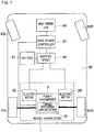
- FIG. 1 is a block diagram showing the conceptual configuration of a vehicle (electric vehicle) provided with the drive source control device and a vehicle driving device.
- This vehicle is a rear wheel drive type, and includes a chassis 60, drive wheels 61L, 61R which are rear wheels, driven wheels 62L, 62R which are front wheels, a vehicle driving device 1, a high-order ECU 66, a drive source control device 67, a battery 63, an inverter device 64, and the like.
- the vehicle driving device 1 includes first and second electric motors 2L, 2R and a power transmission device 3.
- the first and second electric motors 2L, 2R are two drive sources that are mounted to the vehicle and can be controlled independently of each other.
- the power transmission device 3 is provided between the first and second electric motors 2L, 2R and the drive wheels 61L, 61R.
- first and second do not indicate an order but are merely used for discrimination.
- left” and “right” are irrelevant to superiority/inferiority and are merely used for discrimination.
- the high-order ECU 66 is a high-order control device for the drive source control device 67, and for example, has a function of performing integrated control and cooperative control for the entire vehicle, and a function of generating braking/driving torque command values for the left and right drive wheels 61L, 61R.
- the high-order ECU 66 generates braking/driving torque command values (command values for outputs) for left and right, on the basis of an acceleration command outputted from an acceleration manipulation unit (not shown), a deceleration command outputted from a brake manipulation unit (not shown), and a turning command outputted from a steering angle sensor or the like (not shown).
- the drive source control device 67 gives motor torque command values to the inverter device 64 on the basis of the braking/driving torque command values for left and right supplied from the high-order ECU 66.
- the inverter device 64 converts DC power of the battery 63 to AC power for driving the first and second electric motors 2L, 2R.
- the inverter device 64 controls a current supplied from the battery 63 and drives the first and second electric motors 2L, 2R so that torques developed by the first and second electric motors 2L, 2R are equal to the motor torque command values.
- the outputs from the vehicle driving device 1 are transmitted to the left and right drive wheels 61L, 61R via respective constant-velocity joints.
- the drive source control device 67 is, for example, configured from a processor such as a microcomputer, and a memory, or from a hardware module such as ASIC.
- the processor may execute an algorithm, i.e., a procedure, of each module of the drive source control device 67, which is stored in the memory.
- the first and second electric motors 2L, 2R in the vehicle driving device 1 are electric motors having the same maximum output and based on the same standard. As shown in Fig. 2 , the first and second electric motors 2L, 2R have motor housings 4L, 4R, stators 6, 6, and rotors 5, 5, respectively.
- the first and second electric motors 2L, 2R are a radial gap type in which the stators 6, 6 are provided on the inner circumferential surfaces of the motor housings 4L, 4R, and the rotor 5 is provided on the inner circumference of each stator 6 with a gap therebetween.
- the motor housings 4L, 4R have cylindrical motor housing bodies 4aL, 4aR, outer side walls 4bL, 4bR, and inner side walls 4cL, 4cR, respectively.
- the outer side walls 4bL, 4bR close the outer side surfaces on the outboard side of the motor housing bodies 4aL, 4aR.
- the inner side walls 4cL, 4cR are provided on the inner side surfaces on the inboard side of the motor housing bodies 4aL, 4aR, and form separation walls for separation from the power transmission device 3.
- the inner side walls 4cL, 4cR have openings through which motor shafts 5a are led out to the inboard side.
- outboard side a side outward in the vehicle width direction of the vehicle
- inboard side a side toward the center in the vehicle width direction of the vehicle
- the stators 6, 6 are fitted and fixed to the inner circumferential surfaces of the motor housing bodies 4aL, 4aR, respectively.
- Each rotor 5 has the motor shaft 5a at the center part.
- the inner side walls 4cL, 4cR are each provided with a rolling bearing 8a, and the outer side walls 4bL, 4bR are also each provided with a rolling bearing 8b.
- the motor shafts 5a are rotatably supported by the motor housings 4L, 4R via the rolling bearings 8a, 8b, respectively.
- the left and right motor shafts 5a, 5a are provided on the same axis (coaxially).
- the power transmission device 3 has a power transmission device housing 9. Further, the power transmission device 3 has two left and right input gear shafts 12L, 12R, two left and right intermediate gear shafts 13L, 13R, two left and right output gear shafts 14L, 14R, and a torque difference amplification device 30. The power transmission device 3 amplifies a difference between torques (driving torques) inputted from the motor shafts 5a of the first and second electric motors 2L, 2R by the torque difference amplification device 30, and transmits the resultant torques to the drive wheels 61L, 61R ( Fig. 1 ).
- the power transmission device housing 9 houses the above gear shafts and the torque difference amplification device 30.
- the power transmission device housing 9 has such a three-piece structure as to be divided into three pieces in a direction perpendicular to the axial direction of the gear shafts.
- the power transmission device housing 9 has a center housing 9a and left and right lateral housings 9bL, 9bR fixed to respective side surfaces of the center housing 9a.
- the side surfaces on the outboard side of the lateral housings 9bL, 9bR, and the inner side walls 4cL, 4cR, are fixed to each other by a plurality of bolts.
- the two electric motors 2L, 2R are fixed to both left and right ends of the power transmission device housing 9.
- the center housing 9a is provided with a partition wall 11 at the center.
- the power transmission device housing 9 is divided into two chambers at the left and the right by the partition wall 11, and these parts house a body portion of the power transmission device 3.
- the body portion of the power transmission device 3 is symmetric between the left and the right, and includes the input gear shafts 12L, 12R, the intermediate gear shafts 13L, 13R, the output gear shafts 14L, 14R, and the torque difference amplification device 30.
- Each of the input gear shafts 12L, 12R have input gears 12a to which a power is transmitted from the corresponding motor shaft 5a.
- Rolling bearings 17a are provided in bearing fitting holes formed in the partition wall 11, and rolling bearings 17b are provided in bearing fitting holes formed in the left and right lateral housings 9bL, 9bR. Both ends of each input gear shaft 12L, 12R are rotatably supported by the power transmission device housing 9 via the rolling bearings 17a, 17b.
- the input gear shafts 12L, 12R have a hollow structure.
- the inboard-side ends of the motor shafts 5a are inserted into the hollow inner parts of the input gear shafts 12L, 12R.
- the input gear shafts 12L, 12R and the motor shafts 5a are spline-coupled with each other ("serration" coupling is also included; also for spline coupling below, “serration” coupling is included).
- the left and right intermediate gear shafts 13L, 13R are arranged coaxially.
- the intermediate gear shafts 13L, 13R have input-side external gears 13a, 13a which are engaged with the input gears 12a, 12a and have a large diameter, and output-side small-diameter gears 13b, 13b which are engaged with output gears 14a, 14a described later.
- Rolling bearings 20a are provided in bearing fitting holes 19a formed in the partition wall 11, and rolling bearings 20b are provided in bearing fitting holes 19b formed in the left and right lateral housings 9bL, 9bR. Both ends of each intermediate gear shaft 13L, 13R are rotatably supported by the power transmission device housing 9 via the rolling bearings 20a, 20b.
- the bearing fitting holes 19a, 19b have stepped shapes on which outer ring end surfaces of the rolling bearings 20a, 20b abut, and penetrate so that first and second connection members 31, 32 described later pass therethrough.
- the torque difference amplification device 30 is assembled coaxially with the intermediate gear shafts 13L, 13R.
- the torque difference amplification device 30 amplifies a difference between torques (driving torques) supplied from the two electric motors 2L, 2R ( Fig. 2 ).
- the torque difference amplification device 30 has two planetary gear mechanisms 30L, 30R each having three elements and two degrees of freedom.
- a single-pinion planetary gear mechanism is employed for the planetary gear mechanisms 30L, 30R.
- the two planetary gear mechanisms 30L, 30R are provided coaxially.
- the planetary gear mechanisms 30L, 30R have ring gears R L , R R , sun gears S L , S R , planetary gears P L , P R , and planetary carriers C L , C R , respectively. Further, the planetary gear mechanisms 30L, 30R have the first and second connection members 31, 32 shared therebetween.
- the ring gears R L , R R are internal gears assembled into the input-side external gears 13a, 13a of the intermediate gear shafts 13L, 13R, respectively.
- the sun gears S L , S R are sun gears provided coaxially with the ring gears R L , R R .
- the planetary gears P L , P R are revolution gears engaged with the respective ring gears R L , R R and the respective sun gears S L , S R .
- the planetary carriers C L , C R are connected to the planetary gears P L , P R and provided coaxially with the ring gears R L , R R , respectively.
- the output-side small-diameter gears 13b, 13b of the intermediate gear shafts 13L, 13R are connected to the planetary carriers C L , C R , respectively.
- the first connection member 31 couples the left planetary carrier C L which is a constituent member of the planetary gear mechanism 30L at the left in the drawing in Fig. 3 , and the right sun gear S R which is a constituent member of the planetary gear mechanism 30R at the right in the drawing in Fig. 3 .
- the second connection member 32 couples the left sun gear S L which is a constituent member of the planetary gear mechanism 30L at the left in the drawing in Fig. 3 , and the other planetary carrier C R which is a constituent member of the planetary gear mechanism 30R at the right in the drawing in Fig. 3 .
- the planetary carriers C L , C R have carrier pins 33, 33 supporting the planetary gears P L , P R , carrier flanges 34a, 34a on the outboard side, and carrier flanges 34b, 34b on the inboard side, respectively.
- the planetary gears P L , P R are supported by the carrier pins 33, 33 via needle roller bearings 37, 37, respectively.
- the carrier flanges 34a, 34a on the outboard side are connected to the outboard-side end portions of the carrier pins 33, 33, respectively.
- the carrier flanges 34b, 34b on the inboard side are connected to the inboard-side end portions of the carrier pins 33, 33, respectively.
- the carrier flanges 34a, 34a on the outboard side have hollow shaft portions 35, 35 extending toward the outboard side, respectively.
- the outboard-side ends of the hollow shaft portions 35, 35 are supported via the rolling bearings 20b, 20b by the bearing fitting holes 19b, 19b formed in the lateral housings 9bL, 9bR, respectively.
- the carrier flanges 34b, 34b on the inboard side have hollow shaft portions 36, 36 extending toward the inboard side.
- the inboard-side ends of the hollow shaft portions 36, 36 are supported via the rolling bearings 20a, 20a by the bearing fitting holes 19a, 19a formed in the partition wall 11, respectively.
- the rolling bearings 39a, 39b are provided between the ring gear R L and the outer circumferential surfaces of the carrier flanges 34a, 34b of the planetary gear mechanism 30L at the left in the drawing, and between the ring gear R R and the outer circumferential surfaces of the carrier flanges 34a, 34b of the planetary gear mechanism 30R at the right in the drawing.
- the first and second connection members 31, 32 connecting the two planetary gear mechanisms 30L, 30R to each other are provided so as to penetrate the partition wall 11 which partitions the center housing 9a ( Fig. 2 ) into the left and right chambers.
- the first and second connection members 31, 32 are located coaxially with each other, and are rotatably supported in the axial direction by a thrust bearing 47 and rotatably supported in the radial direction by a deep groove ball bearing 49. Further, besides the bearings 47, 49, additional bearings 45, 46 and a thrust bearing 48 are provided between the first and second connection members 31, 32.
- Each of the additional bearings 45, 46 is a needle roller bearing.
- the second connection member 32 has a hollow shaft, and the first connection member 31 has a shaft to be inserted into the hollow shaft.
- the outer circumferential surface on the outboard side at the right in the drawing in Fig. 3 , of the second connection member 32, and the hollow shaft portion 36 of the carrier flange 34b on the inboard side, of the planetary carrier C R , have splines to be engaged with each other.
- the second connection member 32 is connected to the planetary carrier C R by spline fitting.
- the planetary carrier C R which is a second rotary member rotates integrally with the second connection member 32.
- the outer circumferential surface on the outboard side at the left in the drawing in Fig. 3 , of the first connection member 31, and the hollow shaft portion 35 of the carrier flange 34a on the outboard side, of the planetary carrier C L , have splines to be engaged with each other.
- the first connection member 31 is connected to the planetary carrier C L by spline fitting.
- the planetary carrier C L which is a first rotary member rotates integrally with the first connection member 31.
- the first and second connection members 31, 32 are respectively connected to the planetary carriers C L , C R by spline fitting. Therefore, the two planetary gear mechanisms 30L, 30R can be divided to the left and the right, and can be assembled into the three-piece-structure power transmission device housing 9 from the left and the right, together with another speed reducing gear shaft.
- the end portion on the planetary carrier C L side of the second connection member 32 has, on the outer circumferential surface thereof, an external gear forming the sun gear S L of the planetary gear mechanism 30L at the left in the drawing in Fig. 3 .
- the external gear forming the sun gear S L is engaged with the planetary gear P L .
- the first connection member 31 has a large-diameter portion 43 at an end on the planetary gear mechanism 30R side at the right in the drawing in Fig. 3 .
- the outer circumferential surface of the large-diameter portion 43 has an external gear forming the sun gear S R of the planetary gear mechanism 30R at the right in the drawing in Fig. 3 .
- the external gear forming the sun gear S R is engaged with the planetary gear P R .
- the thrust bearings 47, 48 are provided at both ends in the axial direction of the second connection member 32. By these thrust bearings 47, 48, axial-direction movements of sliding of the spline fitting parts between the first and second connection members 31, 32 and the planetary carriers C L , C R are restricted, respectively.
- An end portion at the right in the drawing in Fig. 3 , of the first connection member 31, is supported by the deep groove ball bearing 49 with respect to the planetary carrier C R .
- the first connection member 31 has an oil hole at the axis thereof.
- the output gear shafts 14L, 14R have large-diameter output gears 14a, 14a, respectively.
- Rolling bearings 54a, 54a are provided in bearing fitting holes formed in the partition wall 11, and rolling bearings 54b, 54b are provided in bearing fitting holes formed in the left and right lateral housings 9bL, 9bR, respectively.
- the output gear shafts 14L, 14R are each rotatably supported by the power transmission device housing 9 via the rolling bearings 54a, 54b.
- the outboard-side ends of the output gear shafts 14L, 14R are led out to the outside of the power transmission device housing 9 through openings formed in the lateral housings 9bL, 9bR, respectively.
- Outer joint portions of constant-velocity joints 65a are spline-coupled with the outer circumferential surfaces at the outboard-side ends of the output gear shafts 14L, 14R that are led out.
- the constant-velocity joints 65a are connected to the respective drive wheels 61L, 61R ( Fig. 1 ) via intermediate shafts and the like (not shown).
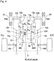
- Fig. 4 is a skeleton diagram showing the vehicle driving device.
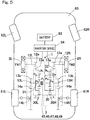
- Fig. 5 illustrates an electric vehicle to which the vehicle driving device is mounted.
- the left and right electric motors 2L, 2R are individually controlled by the drive source control device 67 ( Fig. 1 ), and thus can generate and output different torques.
- the torques of the electric motors 2L, 2R are respectively amplified in accordance with the gear ratios between the input gear 12a, 12a of the input gear shafts 12L, 12R and the large-diameter input-side external gears 13a, 13a of the intermediate gear shafts 13L, 13R in the power transmission device 3, and then transmitted to the ring gears R L , R R of the torque difference amplification device 30. Then, the torque difference between the left and the right is amplified by the torque difference amplification device 30, and the resultant torques are transmitted to the output-side small-diameter gears 13b, 13b.
- the torques are further amplified in accordance with the gear ratios between the output-side small-diameter gears 13b, 13b and the output gears 14a, 14a, respectively, and the resultant torques are outputted to the drive wheels 61L, 61R.
- the planetary gear mechanisms 30L, 30R of the torque difference amplification device 30 respectively include: the sun gears S L , S R and the ring gears R L , R R , which are provided coaxially; the planetary gears P L , P R located between the sun gears S L , S R and the ring gears R L , R R ; and the planetary carriers C L , C R which rotatably support the planetary gears P L , P R and are provided coaxially with the sun gears S L , S R and the ring gears R L , R R .
- the sun gears S L , S R and the planetary gears P L , P R are external-tooth gears having gear teeth on the outer circumferences
- the ring gears R L , R R are internal-tooth gears having gear teeth on the inner circumferences.
- the planetary gears P L , P R are engaged with the sun gears S L , S R and the ring gears R L , R R , respectively.
- the torque difference amplification device 30 is configured such that the left planetary gear mechanism 30L including the sun gear S L , the planetary carrier C L , the planetary gear P L , and the ring gear R L , and the right planetary gear mechanism 30R including the sun gear S R , the planetary carrier C R , the planetary gear P R , and the ring gear R R , are assembled together on a common axis, as described above.
- the first connection member 31 is formed to couple the planetary carrier C L which is a constituent member of the left planetary gear mechanism 30L, and the sun gear S R which is a constituent member of the right planetary gear mechanism 30R.
- the second connection member 32 is formed to couple the sun gear S L which is a constituent member of the left planetary gear mechanism 30L, and the planetary carrier C R which is a constituent member of the right planetary gear mechanism 30R.
- a torque TM1 generated by the left electric motor 2L is transmitted from the input gear shaft 12L to the intermediate gear shaft 13L. Then, while the torque difference between the left and the right is amplified by the torque difference amplification device 30, the torque transmitted to the intermediate gear shaft 13L is sequentially transmitted via the left planetary gear mechanism 30L to the output-side small-diameter gear 13b and the output gear 14a of the intermediate gear shaft 13L, and then the output gear shaft 14L. Then, a driving torque TL ( Fig. 6 ) is outputted from the output gear shaft 14L to the drive wheel 61L.
- a torque TM2 generated by the right electric motor 2R is transmitted from the input gear shaft 12R to the intermediate gear shaft 13R. Then, while the torque difference between the left and the right is amplified by the torque difference amplification device 30, the torque transmitted to the intermediate gear shaft 13R is sequentially transmitted via the right planetary gear mechanism 30R to the output-side small-diameter gear 13b and the output gear 14a of the intermediate gear shaft 13R, and then the output gear shaft 14R. Then, a driving torque TR ( Fig. 6 ) is outputted from the output gear shaft 14R to the drive wheel 61R.
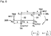
- the torque difference amplification device 30 Since the torque difference amplification device 30 is formed from the assembly of the two identical single-pinion planetary gear mechanisms 30L, 30R, the torque difference amplification device 30 can be expressed by two velocity diagrams as shown in Fig. 6 .
- the two velocity diagrams are shifted upward and downward, so that the upper side in the drawing in Fig. 6 shows the velocity diagram of the left planetary gear mechanism 30L, and the lower side in the drawing in Fig. 6 shows the velocity diagram of the right planetary gear mechanism 30R.
- the torques TM1 and TM2 outputted from the respective electric motors 2L, 2R are respectively inputted to the ring gears R L , R R via the input-side external gears 13a, 13a engaged with the input gears 12a, 12a of the input gear shafts 12L, 12R, and thus the magnitudes of the torques TM1 and TM2 are changed in accordance with the reduction ratios.
- the driving torques TL, TR outputted from the torque difference amplification device 30 are respectively transmitted to the left and right drive wheels 61L, 61R via the output-side small-diameter gears 13b, 13b engaged with the output gears 14a, 14a, and thus the magnitudes of the driving torques TL, TR are changed in accordance with the reduction ratios.
- the distance between the ring gear R L and the planetary carrier C L is equal to the distance between the ring gear R and the planetary carrier C R .
- This distance is defined as "a”.
- the distance between the sun gear S L and the planetary carrier C L is equal to the distance between the sun gear S R and the planetary carrier C R . This distance is defined as "b”.
- the ratio between the length from the respective planetary carriers C L , C R to the ring gears R L , R R is equal to the ratio between a reciprocal (1/Zr) of a number Zr of teeth of the ring gear R L , R R .
- (2a + b) / b represents a torque difference amplification factor ⁇ .
- ⁇ (Zr + 2Zs) / Zr is obtained. That is, the following torque difference amplification factor ⁇ is obtained.
- ⁇ Zr + 2 Zs / Zr
- the torques from the electric motors 2L, 2R are inputted to the ring gears R L , R R , respectively, and the torques to the drive wheels 61L, 61R ( Fig. 5 ) are outputted from the sun gears and the planetary carriers, i.e., S R + C L and S L + C R , respectively.
- the rotation angular velocities of the left and right electric motors 2L, 2R also depend on the rotation angular velocities of the left and right drive wheels 61L, 61R and the numbers of teeth of the gears included in the power transmission device 3.
- the numbers of teeth of the gears included in the power transmission device 3 are the numbers of teeth of the gears of the input gear shafts 12L, 12R, the intermediate gear shafts 13L, 13R, the output gear shafts 14L, 14R, and the torque difference amplification device 30 as shown in Fig. 2 .
- the "numbers of teeth of the gears included in the power transmission device 3" are simply referred to as "numbers of teeth of gears”.
- A1, A2, B1, and B2 are constants determined by the numbers of teeth of gears, and they are all positive values.
- Rotating one of the left and right drive wheels 61L, 61R causes rotations of the two electric motors 2L, 2R.
- both of the two electric motors 2L, 2R are to be rotated in order to rotate one drive wheel 61L (61R).
- Fig. 7 is a block diagram of a control system of the drive source control device 67.
- detecting and suppressing overspeed of electric motor 2L, 2R are processed on the basis of the motor rotation speeds of the left and right electric motors 2L, 2R, received from the inverter device 64.
- the inverter device 64 controls a current supplied from the battery 63 in accordance with the motor rotation speeds so that torques developed by the electric motors 2L, 2R become equal to the respective motor torque command values, thereby driving the electric motors 2L, 2R.
- the motor rotation speeds are respectively detected by rotation detection devices such as resolvers each provided to the corresponding electric motor 2L or 2R, for example.
- the drive source control device 67 receives the braking/driving torque command values TL, TR for the respective left and right drive wheels 61L, 61R from a command module 66a of the high-order ECU 66, and receives the motor rotation speeds ⁇ M1, ⁇ M2 of the electric motors 2L, 2R from the inverter device 64.
- the drive source control device 67 includes an overspeed determination module 68, a correction module 69, and a torque conversion module 70.
- the overspeed determination module 68 determines whether or not each of the left electric motor 2L and the right electric motor 2R has reached overspeed.
- the overspeed determination module 68 compares each of the motor rotation speeds ⁇ M1, ⁇ M2 received from the inverter device 64, with a preset threshold value. If the motor rotation speed ⁇ M1 of the left electric motor 2L is greater than the threshold value, the overspeed determination module 68 determines that the left electric motor 2L has reached overspeed. If the motor rotation speed ⁇ M2 of the right electric motor 2R is greater than the threshold value, the overspeed determination module 68 determines that the right electric motor 2L has reached overspeed. Then, the overspeed determination module 68 outputs a result of the determination as to whether or not at least one electric motor has reached overspeed.
- the correction module 69 includes a corrected-torque setting module 71 and a torque command value switching module 72.
- the corrected-torque setting module 71 receives braking/driving torque command values for left and right from the command module 66a of the high-order ECU 66, the motor rotation speeds ⁇ M1, ⁇ M2 from the inverter device 64, and a result of the determination by the overspeed determination module 68.
- the corrected-torque setting module 71 sets corrected braking/driving torque command values for left and right so that the torque of the drive wheel 61L (61R) that has the greater rotation speed, of the left and right drive wheels 61L, 61R, becomes smaller than the value before the correction, or becomes a braking torque, and the torque of the drive wheel 61R (61L) having the smaller rotation speed becomes equal to or smaller than the value before the correction.
- the rotation speeds of the left and right drive wheels 61L, 61R may be calculated from the motor rotation speeds, for example.
- the rotation speeds of the left and right drive wheels 61L, 61R may be detected by rotation sensors (not shown) respectively provided to the drive wheels 61L, 61R.
- the torque command value switching module 72 outputs the braking/driving torque command values received from the high-order ECU 66 to the torque conversion module 70 without change, and in the case where overspeed has occurred in at least one of the left electric motor 2L and the right electric motor 2R, the torque command value switching module 72 outputs the corrected braking/driving torque command values.
- the torque conversion module 70 converts the braking/driving torque command values received from the high-order ECU 66, or the corrected braking/driving torque command values, to motor torque command values so as to be outputted to the inverter device 64.
- Fig. 8 shows an example of the torque command values before correction and the corrected torque command values.
- Fig. 1 and Fig. 7 are also referred to, as necessary.
- the torque difference amplification factor ⁇ is 2
- the reduction ratio ⁇ is 10.
- the motor torque command values are 10 N ⁇ m
- the braking/driving torque command values for the left and right drive wheels 61L, 61R are both 100 N ⁇ m. If overspeed occurs in the left drive wheel 61L, the electric motor 2L reaches overspeed.
- the overspeed determination module 68 determines that the left electric motor 2L has reached overspeed, and outputs the determination result.
- the corrected-torque setting module 71 sets corrected braking/driving torque command values so that the braking/driving torque command value for the left drive wheel 61L becomes zero and the braking/driving torque command value for the right drive wheel 61R is maintained at 100 N ⁇ m.
- the set motor torque command values for the electric motor 2L and the electric motor 2R i.e., the corrected braking/driving torque command values, are 2.5 N ⁇ m and 7.5 N ⁇ m, respectively. In this way, the motor torque command values for the electric motors 2L, 2R are corrected.
- Fig. 9 shows another example of the torque command values before correction and the corrected torque command values.
- the torque difference amplification factor ⁇ is 2
- the reduction ratio ⁇ is 10.
- the motor torque command values are 10 N ⁇ m
- the braking/driving torque command values for the left and right drive wheels 61L, 61R are both 100 N ⁇ m. If overspeed occurs in the left drive wheel 61L, the overspeed determination module 68 determines that the left electric motor 2L has reached overspeed, and outputs the determination result.
- the corrected-torque setting module 71 sets corrected braking/driving torque command values so that the braking/driving torque command value for the left drive wheel 61L becomes -100 N ⁇ m (that is, a braking torque occurs in the left drive wheel 61L), and the braking/driving torque command value for the right drive wheel 61R is maintained at 100 N ⁇ m.
- a braking torque occurs in the left drive wheel 61L in response to the electric motor 2L, in addition to mechanical resistance from the road surface and the driving part. Therefore, it is possible to suppress overspeed of the electric motor 2L more effectively than in the example shown in Fig. 8 .
- the drive source control device 67 may control a friction brake (not shown) provided to the drive wheel 61L, thereby reducing the motor rotation speed of the electric motor 2L.
- the motor torque command values for the electric motors 2L, 2R are adjusted to -5 N ⁇ m and 5 N ⁇ m, respectively, through correction. In this way, the motor torque command values for the electric motors 2L, 2R are corrected.
- the torque to be corrected of the drive wheel that has the greater rotation speed may be determined by, for example, performing feedback control so that the rotation speed becomes equal to or smaller than a reference wheel rotation speed.
- a difference between the rotation speed ⁇ of the wheel and the reference wheel rotation speed ⁇ target is defined as ⁇
- the braking/driving torque command value from the high-order ECU 66 ( Fig. 7 ) is defined as T
- the corrected braking/driving torque command value is defined as T'
- the braking/driving torque command value can be corrected by using expressions (14) and (15).
- the reference wheel rotation speed ⁇ target may be set on the basis of the wheel rotation speed of a driven wheel of the vehicle or the drive wheel that has the smaller rotation speed.
- the reference wheel rotation speed ⁇ target may be set on the basis of the rotation speed of the overspeed drive wheel at the time when overspeed is detected from this drive wheel.
- the corrected-torque setting module 71 sets corrected braking/driving torque command values for left and right so that the torque of the drive wheel 61L (61R) that has the greater rotation speed, of the left and right drive wheels 61L, 61R, becomes smaller than the value before correction, or becomes a braking torque, and the torque of the drive wheel 61R (61L) that has the smaller rotation speed becomes equal to or smaller than the value before correction.
- the torque command value switching module 72 outputs the braking/driving torque command values received from the high-order ECU 66, to the torque conversion module 70, and in the case where overspeed has occurred in the left electric motor 2L or the right electric motor 2R, the torque command value switching module 72 outputs the corrected braking/driving torque command values.
- the torque conversion module 70 converts the braking/driving torque command values received from the high-order ECU 66, or the corrected braking/driving torque command values, to motor torque command values so as to be outputted to the inverter device 64.
- the correction module 69 corrects the command values for outputs of the two electric motors 2L, 2R so that the torque of the drive wheel 61L (61R) that has the greater rotation speed, of the left and right drive wheels 61L, 61R, becomes a braking torque and the torque of the drive wheel 61R (61L) that has the smaller rotation speed becomes equal to or smaller than the value before correction, a braking torque occurs in the drive wheel 61L (61R) that has the greater rotation speed, in response to the electric motor 2L (2R), in addition to mechanical resistance from the road surface and the driving part. Therefore, it is possible to suppress overspeed of the electric motor 2L (2R) more effectively.
- the braking/driving torque command value for the right drive wheel 61R after correction is maintained at the braking/driving torque command value before correction.
- another method may be employed. For example, when overspeed is detected in the left drive wheel 61L, the corrected-torque setting module 71 may decrease the braking/driving torque command value for the right drive wheel 61R in accordance with the amount of decrease in the braking/driving torque command value for the left drive wheel 61L.
- the drive source control device 67 may determine a significant fluctuation of the vehicle attitude. Then, in order to suppress the fluctuation of the vehicle attitude, the drive source control device 67 may reduce the torque of the right drive wheel 61R in accordance with the magnitude of a deviation between the measured yaw rate and the calculated normative or reference yaw rate.
- the drive source control device 67 may calculate a sideslip angle or a sideslip angular velocity on the basis of the measured vehicle speed, lateral acceleration, and yaw rate of the vehicle.
- the drive source control device 67 determines a significant fluctuation of the vehicle attitude, if a large difference from a normative sideslip angle or a normative sideslip angular velocity (sideslip angle or sideslip angular velocity calculated under the assumption that there is no reduction in the torque of the left drive wheel) calculated from a predetermined vehicle model, is determined.
- the drive source control device 67 may reduce the torque of the right drive wheel 61R in accordance with the magnitude of a deviation between the calculated normative sideslip angle and the sideslip angle calculated from the measured vehicle speed and the like, or the magnitude of a deviation between the calculated normative sideslip angular velocity and the sideslip angular velocity calculated from the measured vehicle speed and the like.
- the overspeed determination module 68 of the drive source control device 67 determines whether or not the electric motor 2L, 2R has reached overspeed, on the basis of the motor rotation speed inputted from the inverter device 64.
- the drive source control device 67 according to the present invention is not limited thereto. That is, the drive source control device 67 may receive output values from ABS sensors or pulsar rings which detect the rotation speeds of the left and right drive wheels 61L, 61R, and the overspeed determination module 68 may determine whether or not the electric motor 2L, 2R has reached overspeed, on the basis of the output values.
- the overspeed determination module 69 may calculate the rotation speeds of the electric motors 2L, 2R using these expressions, and compare each rotation speed with a predetermined threshold value, to determine whether or not the electric motor 2L, 2R has reached overspeed.
- the overspeed determination module 68 may determine whether or not the electric motor 2L, 2R has reached overspeed, when the rotation speeds of the left and right drive wheels 61L, 61R satisfy a predetermined condition.
- the predetermined condition is determined through examination and/or simulation, for example.
- the first connection member 31 is formed to couple the planetary carrier C L of the left planetary gear mechanism 30L, and the sun gear S R of the right planetary gear mechanism 30R
- the second connection member 32 is formed to couple the sun gear S L of the left planetary gear mechanism 30L and the planetary carrier C R of the right planetary gear mechanism 30R.
- the configuration is not limited to this example.
- first connection member 31 may be formed to couple the sun gear S L of the left planetary gear mechanism 30L and the ring gear R R of the right planetary gear mechanism 30R
- second connection member 32 may be formed to couple the ring gear R L of the left planetary gear mechanism 30L and the sun gear S R of the right planetary gear mechanism 30R.
- connection member 32 may be formed to couple the planetary carrier C L of the left planetary gear mechanism 30L and the ring gear R R of the right planetary gear mechanism 30R.
- the drive sources of the vehicle driving device are not limited to electric motors, but may be an internal combustion engine such as a gasoline engine.
- the bearings 45, 46 between the first and second connection members 31, 32 may be bearings other than needle roller bearings.
- rolling bearings such as deep groove ball bearings or angular contact ball bearings may be used.
Landscapes
- Engineering & Computer Science (AREA)
- Mechanical Engineering (AREA)
- Power Engineering (AREA)
- Transportation (AREA)
- General Engineering & Computer Science (AREA)
- Electric Propulsion And Braking For Vehicles (AREA)
- Retarders (AREA)
Abstract
Description
- This application is based on and claims Convention priority to Japanese patent application No.
2016-201078, filed October 12, 2016 - The present invention relates to: a drive source control device for transmitting driving torques generated from two independent drive sources, to left and right drive wheels, with a torque difference therebetween amplified; and a vehicle equipped with the drive source control device.
- In order to achieve smooth turning traveling of a vehicle or suppress change in the behavior of a vehicle such as extreme understeer or extreme oversteer, it may be effective to generate a great driving torque difference between left and right drive wheels. A vehicle driving device is thus disclosed in which a gear device having two planetary gear mechanisms combined is provided between two drive sources and left and right drive wheels so as to amplify the torque difference (
Patent Documents 1 and 2). - In these vehicle driving devices, output torques of the two drive sources are determined and controlled on the basis of torque command values for the left and right drive wheels issued from a high-order ECU. The patent documents disclose electric motors as the drive sources.
- In the vehicle driving devices, while a difference between torques of the two drive sources is amplified, a difference in rotation speed is reduced in transmission to the left and right drive wheels. Where the torque amplification factor is defined as α (α > 1), the reduction ratio is defined as β (β ≥ 1), torques of the two drive sources corresponding to the respectively left and right drive wheels are defined as TM1, TM2, and torques of the left and right drive wheels are defined as TWL, TWR, the torque relationship can be represented by the following expressions.


- Similarly, where the rotation speeds of the two drive sources corresponding to the respective left and right drive wheels are defined as ωM1, ωM2 and the rotation speeds of the left and right drive wheels are defined as ωWL, ωWR, the rotation speed relationship can be represented by the following expressions.


- As a method for coping with the case where the electric motor reaches overspeed, a motor control method for detecting overspeed of a motor of an electric vehicle and preventing damage to the motor is disclosed (Patent Document 3).
-
- [Patent Document 1]
JP Laid-open Patent Publication No. 2015-21594 - [Patent Document 2]
JP Patent No. 4907390 - [Patent Document 3]
JP Laid-open Patent Publication No. H08-163702 - In the vehicle driving device shown in
Patent Documents 

- In addition, from expressions (1) and (2), the torques TWL, TWR of the left and right drive wheels are calculated as follows.


- In the case of α > 1 and β ≥ 1, the signs of the coefficients are as follows.

- In a vehicle on which the vehicle driving device is mounted, it is assumed that only the left drive wheel spins while driving torques are applied to the left and right drive wheels (TWL > 0, TWR > 0). Since TWL > 0 and TWR > 0 are satisfied, TM1 > 0 and TM2 > 0 are satisfied according to expressions (1) and (2). Under this condition, when the rotation speed ωWL of the left drive wheel increases, the rotation speed ωM1 of one drive source, i.e., the drive source corresponding to the left drive wheel, greatly increases, and the rotation speed ωM2 of the other drive source, i.e., the drive source corresponding to the right drive wheel decreases, according to expressions (5) and (6).
-
Fig. 10 shows one example. In the case where the left and right drive wheels rotate at 100 r/min (revolutions per minute), if α = 2 and β = 10 are satisfied, the rotation speeds of the drive source M1 corresponding to the left drive wheel and the drive source M2 corresponding to the right drive wheel are 1000 r/min, as shown in diagram (a) ofFig. 10 . Here, if the rotation speed of the left drive wheel increases to 200 r/min, the rotation speed of the drive source M1 increases to 2500 r/min and the rotation speed of the drive source M2 decreases to 500 r/min, as shown in diagram (b) ofFig. 10 . - Next, the following case will be discussed: it is assumed that the rotation speed of the drive source M1 exceeds a permissible rotation speed and reaches overspeed, and the motor control method disclosed in
Patent Document 3 is used to set the torque of the drive source M1 to zero or cause a braking torque. That is, the torque TM1 of the drive source M1 is set as TM1 ≤ 0. In the case where TM1 ≤ 0 is set and the torque TM2 of the drive source M2 that has not reached overspeed is maintained, the torque TWL of the left drive wheel decreases but the torque TWR of the right drive wheel increases, according to expressions (7) and (8). -
Fig. 11 shows one example. As shown in diagram (a) ofFig. 11 , in the case where the drive source M1 and the drive source M2 are outputting torques of 10 N·m, if α = 2 and β = 10 are satisfied, the torques of the left and right drive wheels are 100 N·m. Here, as shown in diagram (b) ofFig. 11 , if the torque of the drive source M1 is adjusted to zero and the torque of the drive source M2 is maintained at 10 N·m, the torque of the left drive wheel becomes -50 N·m and the torque of the right drive wheel becomes 150 N·m, and thus the torque of the right drive wheel increases. - In the above situation, as an example, the case where the vehicle is turning left while accelerating will be considered. In left turning, the left drive wheel is the turning inner wheel, and therefore, if the turning lateral acceleration is great, the left drive wheel spins, so that the drive source M1 reaches overspeed. Under this condition, changing the torque TM1 of the drive source M1 from TM1 > 0 to TM1 ≤ 0 and maintaining the torque of the drive source M2 causes the torque TWL of the left drive wheel to decrease or become a braking torque, resulting in reducing the rotation speeds of the left drive wheel and the drive source M1.
- However, as a result of increase in the torque TWR of the right drive wheel, a yaw moment that promotes turning is generated and thus the vehicle might exhibit a spin behavior. In addition, if the turning is so steep that the turning inner wheel spins, a tire load on the right drive wheel which is the turning outer wheel is also great. Therefore, the tire may spin due to the increase in the driving torque, which causes the tire gripping to be lost. In this case, the vehicle attitude might become further unstable.
- Similarly, in the case of starting to move or accelerating on a split low-µ road surface, the above situation might occur. In the case where the right drive wheel is on an asphalt road surface and the left drive wheel is on a frozen road surface, the left drive wheel is likely to spin at the time of starting to move or accelerating, and as in the above case, when the drive source M1 has reached overspeed, if the torque TM1 of the drive source M1 is set to zero or in a regeneration direction, the torque of the right drive wheel which is on the asphalt road increases, so that the vehicle turns leftward. As a result, the vehicle attitude might become unstable.
- An object of the present invention is to provide: a drive source control device that can suppress increase in the rotation speed of a drive source and suppress occurrence of an unnecessary yaw moment to stabilize the vehicle attitude; and a vehicle equipped with the drive source control device.
- In the following description, the reference characters in the embodiments are used for convenience sake in order to facilitate the understanding.
- A drive
source control device 67 according to the present invention is a drive source control device for controlling twodrive sources drive sources right drive wheels power transmission device 3 disposed among the twodrive sources right drive wheels power transmission device 3 being configured to distribute powers from the twodrive sources right drive wheels respective drive sources right drive wheels overspeed determination module 68 configured to determine whether or not a rotation speed of each of the twodrive sources correction module 69 configured to, when theoverspeed determination module 68 determines that the rotation speed of at least one 2L (2R) of the twodrive sources drive sources command module 66a, thecorrection module 69 correcting the command values for the outputs of the tworespective drive sources drive wheel 61L (61R) that has the greater rotation speed, of the left andright drive wheels drive wheel 61R (61L) that has the smaller rotation speed maintains or decreases from the torque before the correction. - Regarding the determination for whether or not the rotation speed of each
drive source 2L (2R) is overspeed, for example, the rotation speed may be determined to be overspeed when the rotation speed of thedrive source 2L (2R) is greater than a threshold value. Alternatively, the rotation speeds of thedrive sources drive wheels right drive wheels drive sources drive sources - Further alternatively, without using the relational expressions, the
overspeed determination module 68 may determine whether or not thedrive source right drive wheels - The threshold value is any threshold value that is determined depending on designing or the like, and is, for example, determined by figuring out an appropriate threshold value through examination and/or simulation.
- In the above configuration, the
overspeed determination module 68 determines whether or not the rotation speed of each of thedrive sources overspeed determination module 68 determines that the rotation speed of at least onedrive source 2L (2R) is overspeed, thecorrection module 69 corrects the command values for outputs of the twodrive sources command module 66a. - That is, the
correction module 69 corrects the command values for outputs of the twodrive sources drive wheel 61L (61R) that has the greater rotation speed, of the left andright drive wheels drive wheel 61R (61L) that has the smaller rotation speed maintains or decreases from the torque before the correction. The amount of the correction is determined through examination and/or simulation, for example. Correcting the command values for the outputs of the twodrive sources drive wheel 61L (61R) that has the greater rotation speed to decelerate by being subjected to mechanical resistance from the road surface and the driving part. As a result, overspeed of thedrive source 2L (2R) is suppressed. In addition to this, occurrence of an unnecessary yaw moment due to torque increase is suppressed in thecorresponding drive wheel 61L (61R), whereby the vehicle attitude can be stabilized. - The
correction module 69 may correct the command values for the outputs of the twodrive sources drive wheel 61L (61R) that has the greater rotation speed, of the left andright drive wheels drive wheel 61R (61L) that has the smaller rotation speed maintains or decreases from the torque before the correction. In this case, a braking torque occurs in thedrive wheel 61L (61R) that has the greater rotation speed, in response to thedrive source 2L (2R), in addition to mechanical resistance from the road surface and the driving part. Therefore, it is possible to suppress overspeed of thedrive source 2L (2R) more effectively. - The
power transmission device 3 may include a torquedifference amplification device 30. The torquedifference amplification device 30 may have twoplanetary gear mechanisms drive sources difference amplification device 30 amplifying the difference between torques generated by the twodrive sources - A vehicle according to the present invention is the vehicle including the drive
source control device 67. In this case, for example, on a split low-µ road surface or the like, increase in the rotation speed of thedrive source 2L (2R) in which overspeed has occurred is suppressed, and occurrence of an unnecessary yaw moment is suppressed, whereby the vehicle attitude can be stabilized. - Any combination of at least two constructions, disclosed in the appended claims and/or the specification and/or the accompanying drawings should be construed as included within the scope of the present invention. In particular, any combination of two or more of the appended claims should be equally construed as included within the scope of the present invention.
- In any event, the present invention will become more clearly understood from the following description of preferred embodiments thereof, when taken in conjunction with the accompanying drawings. However, the embodiments and the drawings are given only for the purpose of illustration and explanation, and are not to be taken as limiting the scope of the present invention in any way whatsoever, which scope is to be determined by the appended claims. In the accompanying drawings, like reference numerals are used to denote like parts throughout the several views, and:
-
Fig. 1 is a block diagram showing the conceptual configuration of a vehicle provided with a drive source control device according to the first embodiment of the present invention, and a vehicle driving device; -
Fig. 2 is a sectional view of the vehicle driving device shown inFig. 1 ; -
Fig. 3 is an enlarged sectional view showing a torque difference amplification device part of the vehicle driving device shown inFig. 1 ; -
Fig. 4 is a skeleton diagram showing the vehicle driving device shown inFig. 1 ; -
Fig. 5 illustrates an electric vehicle to which the vehicle driving device shown inFig. 1 is mounted; -
Fig. 6 shows velocity diagrams for illustrating a torque difference amplification factor of the vehicle driving device shown inFig. 1 ; -
Fig. 7 is a block diagram of a control system of the drive source control device shown inFig. 1 ; -
Fig. 8 is a diagram showing an example of torque command values corrected by the drive source control device shown inFig. 1 ; -
Fig. 9 is a diagram showing another example of torque command values corrected by the drive source control device shown inFig. 1 ; -
Fig. 10 is a diagram showing an example of drive wheel rotation speeds and drive source rotation speeds in a conventional vehicle driving device; and -
Fig. 11 is a diagram showing an example of drive wheel torques and drive source torques before and after correction in the conventional vehicle driving device. - A drive source control device according to the first embodiment of the present invention and a vehicle provided with the drive source control device will be described with reference to
Fig. 1 to Fig. 9 .Fig. 1 is a block diagram showing the conceptual configuration of a vehicle (electric vehicle) provided with the drive source control device and a vehicle driving device. This vehicle is a rear wheel drive type, and includes achassis 60,drive wheels wheels vehicle driving device 1, a high-order ECU 66, a drivesource control device 67, abattery 63, aninverter device 64, and the like. - The
vehicle driving device 1 includes first and secondelectric motors power transmission device 3. The first and secondelectric motors power transmission device 3 is provided between the first and secondelectric motors drive wheels - The high-
order ECU 66 is a high-order control device for the drivesource control device 67, and for example, has a function of performing integrated control and cooperative control for the entire vehicle, and a function of generating braking/driving torque command values for the left andright drive wheels order ECU 66 generates braking/driving torque command values (command values for outputs) for left and right, on the basis of an acceleration command outputted from an acceleration manipulation unit (not shown), a deceleration command outputted from a brake manipulation unit (not shown), and a turning command outputted from a steering angle sensor or the like (not shown). - The drive
source control device 67 gives motor torque command values to theinverter device 64 on the basis of the braking/driving torque command values for left and right supplied from the high-order ECU 66. Thus, the first and secondelectric motors inverter device 64 converts DC power of thebattery 63 to AC power for driving the first and secondelectric motors inverter device 64 controls a current supplied from thebattery 63 and drives the first and secondelectric motors electric motors vehicle driving device 1 are transmitted to the left andright drive wheels source control device 67 is, for example, configured from a processor such as a microcomputer, and a memory, or from a hardware module such as ASIC. In the case where the drivesource control device 67 is configured from a processor and a memory, the processor may execute an algorithm, i.e., a procedure, of each module of the drivesource control device 67, which is stored in the memory. - In the present embodiment, the first and second
electric motors vehicle driving device 1 are electric motors having the same maximum output and based on the same standard. As shown inFig. 2 , the first and secondelectric motors motor housings stators rotors electric motors stators motor housings rotor 5 is provided on the inner circumference of eachstator 6 with a gap therebetween. - The
motor housings power transmission device 3. The inner side walls 4cL, 4cR have openings through whichmotor shafts 5a are led out to the inboard side. As used herein, in a state where thevehicle driving device 1 is mounted to the vehicle, a side outward in the vehicle width direction of the vehicle is referred to as outboard side, and a side toward the center in the vehicle width direction of the vehicle is referred to as inboard side. - The
stators rotor 5 has themotor shaft 5a at the center part. The inner side walls 4cL, 4cR are each provided with a rollingbearing 8a, and the outer side walls 4bL, 4bR are also each provided with a rollingbearing 8b. Themotor shafts 5a are rotatably supported by themotor housings bearings right motor shafts - The
power transmission device 3 has a power transmission device housing 9. Further, thepower transmission device 3 has two left and rightinput gear shafts intermediate gear shafts output gear shafts difference amplification device 30. Thepower transmission device 3 amplifies a difference between torques (driving torques) inputted from themotor shafts 5a of the first and secondelectric motors difference amplification device 30, and transmits the resultant torques to thedrive wheels Fig. 1 ). - The power transmission device housing 9 houses the above gear shafts and the torque
difference amplification device 30. The power transmission device housing 9 has such a three-piece structure as to be divided into three pieces in a direction perpendicular to the axial direction of the gear shafts. Specifically, the power transmission device housing 9 has acenter housing 9a and left and right lateral housings 9bL, 9bR fixed to respective side surfaces of thecenter housing 9a. - The side surfaces on the outboard side of the lateral housings 9bL, 9bR, and the inner side walls 4cL, 4cR, are fixed to each other by a plurality of bolts. Thus, the two
electric motors center housing 9a is provided with a partition wall 11 at the center. The power transmission device housing 9 is divided into two chambers at the left and the right by the partition wall 11, and these parts house a body portion of thepower transmission device 3. The body portion of thepower transmission device 3 is symmetric between the left and the right, and includes theinput gear shafts intermediate gear shafts output gear shafts difference amplification device 30. - Each of the
input gear shafts corresponding motor shaft 5a.Rolling bearings 17a are provided in bearing fitting holes formed in the partition wall 11, and rollingbearings 17b are provided in bearing fitting holes formed in the left and right lateral housings 9bL, 9bR. Both ends of eachinput gear shaft bearings input gear shafts motor shafts 5a are inserted into the hollow inner parts of theinput gear shafts input gear shafts motor shafts 5a are spline-coupled with each other ("serration" coupling is also included; also for spline coupling below, "serration" coupling is included). - As shown in
Fig. 3 , the left and rightintermediate gear shafts intermediate gear shafts external gears output gears Rolling bearings 20a are provided in bearing fitting holes 19a formed in the partition wall 11, and rollingbearings 20b are provided in bearingfitting holes 19b formed in the left and right lateral housings 9bL, 9bR. Both ends of eachintermediate gear shaft bearings fitting holes 19a, 19b have stepped shapes on which outer ring end surfaces of the rollingbearings second connection members - To the
intermediate gear shafts difference amplification device 30 is assembled coaxially with theintermediate gear shafts difference amplification device 30 amplifies a difference between torques (driving torques) supplied from the twoelectric motors Fig. 2 ). The torquedifference amplification device 30 has twoplanetary gear mechanisms planetary gear mechanisms planetary gear mechanisms - The
planetary gear mechanisms planetary gear mechanisms second connection members external gears intermediate gear shafts intermediate gear shafts - The
first connection member 31 couples the left planetary carrier CL which is a constituent member of theplanetary gear mechanism 30L at the left in the drawing inFig. 3 , and the right sun gear SR which is a constituent member of theplanetary gear mechanism 30R at the right in the drawing inFig. 3 . Thesecond connection member 32 couples the left sun gear SL which is a constituent member of theplanetary gear mechanism 30L at the left in the drawing inFig. 3 , and the other planetary carrier CR which is a constituent member of theplanetary gear mechanism 30R at the right in the drawing inFig. 3 . - The planetary carriers CL, CR have carrier pins 33, 33 supporting the planetary gears PL, PR,
carrier flanges carrier flanges needle roller bearings carrier flanges carrier flanges - The
carrier flanges hollow shaft portions hollow shaft portions bearings fitting holes carrier flanges hollow shaft portions hollow shaft portions bearings bearings carrier flanges planetary gear mechanism 30L at the left in the drawing, and between the ring gear RR and the outer circumferential surfaces of thecarrier flanges planetary gear mechanism 30R at the right in the drawing. - The first and
second connection members planetary gear mechanisms center housing 9a (Fig. 2 ) into the left and right chambers. The first andsecond connection members thrust bearing 47 and rotatably supported in the radial direction by a deepgroove ball bearing 49. Further, besides thebearings additional bearings thrust bearing 48 are provided between the first andsecond connection members additional bearings second connection member 32 has a hollow shaft, and thefirst connection member 31 has a shaft to be inserted into the hollow shaft. - The outer circumferential surface on the outboard side at the right in the drawing in
Fig. 3 , of thesecond connection member 32, and thehollow shaft portion 36 of thecarrier flange 34b on the inboard side, of the planetary carrier CR, have splines to be engaged with each other. Thus, thesecond connection member 32 is connected to the planetary carrier CR by spline fitting. Accordingly, the planetary carrier CR which is a second rotary member rotates integrally with thesecond connection member 32. - The outer circumferential surface on the outboard side at the left in the drawing in
Fig. 3 , of thefirst connection member 31, and thehollow shaft portion 35 of thecarrier flange 34a on the outboard side, of the planetary carrier CL, have splines to be engaged with each other. Thus, thefirst connection member 31 is connected to the planetary carrier CL by spline fitting. Accordingly, the planetary carrier CL which is a first rotary member rotates integrally with thefirst connection member 31. - As described above, the first and
second connection members planetary gear mechanisms second connection member 32 has, on the outer circumferential surface thereof, an external gear forming the sun gear SL of theplanetary gear mechanism 30L at the left in the drawing inFig. 3 . The external gear forming the sun gear SL is engaged with the planetary gear PL. - The
first connection member 31 has a large-diameter portion 43 at an end on theplanetary gear mechanism 30R side at the right in the drawing inFig. 3 . The outer circumferential surface of the large-diameter portion 43 has an external gear forming the sun gear SR of theplanetary gear mechanism 30R at the right in the drawing inFig. 3 . The external gear forming the sun gear SR is engaged with the planetary gear PR. Thethrust bearings second connection member 32. By thesethrust bearings second connection members Fig. 3 , of thefirst connection member 31, is supported by the deepgroove ball bearing 49 with respect to the planetary carrier CR. Thefirst connection member 31 has an oil hole at the axis thereof. - As shown in
Fig. 2 , theoutput gear shafts Rolling bearings bearings output gear shafts bearings - The outboard-side ends of the
output gear shafts velocity joints 65a are spline-coupled with the outer circumferential surfaces at the outboard-side ends of theoutput gear shafts velocity joints 65a are connected to therespective drive wheels Fig. 1 ) via intermediate shafts and the like (not shown). -
Fig. 4 is a skeleton diagram showing the vehicle driving device.Fig. 5 illustrates an electric vehicle to which the vehicle driving device is mounted. As shown inFig. 4 andFig. 5 , the left and rightelectric motors Fig. 1 ), and thus can generate and output different torques. - The torques of the
electric motors input gear input gear shafts external gears intermediate gear shafts power transmission device 3, and then transmitted to the ring gears RL, RR of the torquedifference amplification device 30. Then, the torque difference between the left and the right is amplified by the torquedifference amplification device 30, and the resultant torques are transmitted to the output-side small-diameter gears 13b, 13b. Then, the torques are further amplified in accordance with the gear ratios between the output-side small-diameter gears 13b, 13b and the output gears 14a, 14a, respectively, and the resultant torques are outputted to thedrive wheels - The
planetary gear mechanisms difference amplification device 30 respectively include: the sun gears SL, SR and the ring gears RL, RR, which are provided coaxially; the planetary gears PL, PR located between the sun gears SL, SR and the ring gears RL, RR; and the planetary carriers CL, CR which rotatably support the planetary gears PL, PR and are provided coaxially with the sun gears SL, SR and the ring gears RL, RR. Here, the sun gears SL, SR and the planetary gears PL, PR are external-tooth gears having gear teeth on the outer circumferences, and the ring gears RL, RR are internal-tooth gears having gear teeth on the inner circumferences. The planetary gears PL, PR are engaged with the sun gears SL, SR and the ring gears RL, RR, respectively. - In the
planetary gear mechanisms Fig. 6 , the ring gears RL, RR and the sun gears SL, SR are depicted on opposite sides with respect to the planetary carriers CL, CR. - As shown in
Fig. 4 andFig. 5 , the torquedifference amplification device 30 is configured such that the leftplanetary gear mechanism 30L including the sun gear SL, the planetary carrier CL, the planetary gear PL, and the ring gear RL, and the rightplanetary gear mechanism 30R including the sun gear SR, the planetary carrier CR, the planetary gear PR, and the ring gear RR, are assembled together on a common axis, as described above. - The
first connection member 31 is formed to couple the planetary carrier CL which is a constituent member of the leftplanetary gear mechanism 30L, and the sun gear SR which is a constituent member of the rightplanetary gear mechanism 30R. Thesecond connection member 32 is formed to couple the sun gear SL which is a constituent member of the leftplanetary gear mechanism 30L, and the planetary carrier CR which is a constituent member of the rightplanetary gear mechanism 30R. - A torque TM1 generated by the left
electric motor 2L is transmitted from theinput gear shaft 12L to theintermediate gear shaft 13L. Then, while the torque difference between the left and the right is amplified by the torquedifference amplification device 30, the torque transmitted to theintermediate gear shaft 13L is sequentially transmitted via the leftplanetary gear mechanism 30L to the output-side small-diameter gear 13b and theoutput gear 14a of theintermediate gear shaft 13L, and then theoutput gear shaft 14L. Then, a driving torque TL (Fig. 6 ) is outputted from theoutput gear shaft 14L to thedrive wheel 61L. - A torque TM2 generated by the right
electric motor 2R is transmitted from theinput gear shaft 12R to theintermediate gear shaft 13R. Then, while the torque difference between the left and the right is amplified by the torquedifference amplification device 30, the torque transmitted to theintermediate gear shaft 13R is sequentially transmitted via the rightplanetary gear mechanism 30R to the output-side small-diameter gear 13b and theoutput gear 14a of theintermediate gear shaft 13R, and then theoutput gear shaft 14R. Then, a driving torque TR (Fig. 6 ) is outputted from theoutput gear shaft 14R to thedrive wheel 61R. - Here, driving torques transmitted by the torque
difference amplification device 30 will be described with reference to the velocity diagrams shown inFig. 6 . Since the torquedifference amplification device 30 is formed from the assembly of the two identical single-pinionplanetary gear mechanisms difference amplification device 30 can be expressed by two velocity diagrams as shown inFig. 6 . Here, for facilitating the understanding, the two velocity diagrams are shifted upward and downward, so that the upper side in the drawing inFig. 6 shows the velocity diagram of the leftplanetary gear mechanism 30L, and the lower side in the drawing inFig. 6 shows the velocity diagram of the rightplanetary gear mechanism 30R. - In practice, as shown in
Fig. 5 , the torques TM1 and TM2 outputted from the respectiveelectric motors external gears input gear shafts difference amplification device 30 are respectively transmitted to the left andright drive wheels - Although the torques are changed in accordance with the above reduction ratios in this vehicle driving device, hereinafter, for facilitating the understanding, as shown in
Fig. 6 , it is assumed that the reduction ratios are 1, and thus the torques inputted to the ring gears RL, RR remain TM1, TM2, and the driving torques remain TL, TR, in the description of the velocity diagrams and calculation expressions. - In the two single-pinion
planetary gear mechanisms - The ratio between the length from the respective planetary carriers CL, CR to the ring gears RL, RR is equal to the ratio between a reciprocal (1/Zr) of a number Zr of teeth of the ring gear RL, RR. The ratio between the length from the respective planetary carriers CL, CR to the sun gears SL, SR is equal to the ratio between a reciprocal (1/Zs) of a number Zs of teeth of the sun gear SL, SR. Therefore, a = (1/Zr) and b = (1/Zs) are satisfied.
- From balance of a moment M with a point of RR as a reference, the following expression (9) is satisfied. In
Fig. 6 , an arrow direction M in the drawing is the positive direction of the moment.
- From balance of a moment M with a point of RL as a reference, the following expression (10) is satisfied.

- From expression (9) + expression (10), the following expression (11) is obtained.


- In expression (11), (2a + b) / b represents a torque difference amplification factor α. By substituting a = 1/Zr and b = 1/Zs, α = (Zr + 2Zs) / Zr is obtained. That is, the following torque difference amplification factor α is obtained.

- In this example, the torques from the
electric motors Fig. 5 ) are inputted to the ring gears RL, RR, respectively, and the torques to thedrive wheels Fig. 5 ) are outputted from the sun gears and the planetary carriers, i.e., SR + CL and SL + CR, respectively. - As shown in
Fig. 5 andFig. 6 , in the case where a difference between the rotation speeds of thefirst connection member 31 and thesecond connection member 32 is small, if different torques TM1, TM2 are generated from the twoelectric motors difference amplification device 30, whereby a driving torque difference α ∗ ΔTIN greater than the input torque difference ΔTIN can be obtained. - That is, even if the input torque difference ΔTIN is small, the input torque difference ΔTIN can be amplified with the torque difference amplification factor α (= (Zr + 2Zs) / Zr) by the torque
difference amplification device 30. Thus, a driving torque difference ΔTOUT (= α ∗ (TM2 - TM1)) greater than the input torque difference ΔTIN can be supplied between the driving torques TL, TR transmitted to theleft drive wheel 61L and theright drive wheel 61R. - As shown in
Fig. 1 , the rotation angular velocities of the left and rightelectric motors right drive wheels power transmission device 3. It is noted that the numbers of teeth of the gears included in thepower transmission device 3 are the numbers of teeth of the gears of theinput gear shafts intermediate gear shafts output gear shafts difference amplification device 30 as shown inFig. 2 . Hereinafter, the "numbers of teeth of the gears included in thepower transmission device 3" are simply referred to as "numbers of teeth of gears". - If the rotation speeds of the left and right
electric motors Fig. 1 are respectively defined as ωM1, ωM2, and the rotation speeds of the left andright drive wheels 

right drive wheels electric motors electric motors drive wheel 61L (61R). -
Fig. 7 is a block diagram of a control system of the drivesource control device 67. - As shown in
Fig. 1 andFig. 7 , in the drivesource control device 67, detecting and suppressing overspeed ofelectric motor electric motors inverter device 64. Theinverter device 64 controls a current supplied from thebattery 63 in accordance with the motor rotation speeds so that torques developed by theelectric motors electric motors electric motor - The drive
source control device 67 receives the braking/driving torque command values TL, TR for the respective left andright drive wheels command module 66a of the high-order ECU 66, and receives the motor rotation speeds ωM1, ωM2 of theelectric motors inverter device 64. The drivesource control device 67 includes anoverspeed determination module 68, acorrection module 69, and atorque conversion module 70. Theoverspeed determination module 68 determines whether or not each of the leftelectric motor 2L and the rightelectric motor 2R has reached overspeed. Specifically, theoverspeed determination module 68 compares each of the motor rotation speeds ωM1, ωM2 received from theinverter device 64, with a preset threshold value. If the motor rotation speed ωM1 of the leftelectric motor 2L is greater than the threshold value, theoverspeed determination module 68 determines that the leftelectric motor 2L has reached overspeed. If the motor rotation speed ωM2 of the rightelectric motor 2R is greater than the threshold value, theoverspeed determination module 68 determines that the rightelectric motor 2L has reached overspeed. Then, theoverspeed determination module 68 outputs a result of the determination as to whether or not at least one electric motor has reached overspeed. - The
correction module 69 includes a corrected-torque setting module 71 and a torque commandvalue switching module 72. The corrected-torque setting module 71 receives braking/driving torque command values for left and right from thecommand module 66a of the high-order ECU 66, the motor rotation speeds ωM1, ωM2 from theinverter device 64, and a result of the determination by theoverspeed determination module 68. The corrected-torque setting module 71 sets corrected braking/driving torque command values for left and right so that the torque of thedrive wheel 61L (61R) that has the greater rotation speed, of the left andright drive wheels drive wheel 61R (61L) having the smaller rotation speed becomes equal to or smaller than the value before the correction. - The rotation speeds of the left and
right drive wheels right drive wheels drive wheels electric motors - In accordance with a result of the determination by the
overspeed determination module 68, in a normal case, the torque commandvalue switching module 72 outputs the braking/driving torque command values received from the high-order ECU 66 to thetorque conversion module 70 without change, and in the case where overspeed has occurred in at least one of the leftelectric motor 2L and the rightelectric motor 2R, the torque commandvalue switching module 72 outputs the corrected braking/driving torque command values. Thetorque conversion module 70 converts the braking/driving torque command values received from the high-order ECU 66, or the corrected braking/driving torque command values, to motor torque command values so as to be outputted to theinverter device 64. -
Fig. 8 shows an example of the torque command values before correction and the corrected torque command values. In the following description,Fig. 1 andFig. 7 are also referred to, as necessary. In this example, it is assumed that the torque difference amplification factor α is 2, and the reduction ratio β is 10. Before correction, as shown in diagram (a) ofFig. 8 , the motor torque command values are 10 N·m, and the braking/driving torque command values for the left andright drive wheels left drive wheel 61L, theelectric motor 2L reaches overspeed. Theoverspeed determination module 68 then determines that the leftelectric motor 2L has reached overspeed, and outputs the determination result. - As shown in diagram (b) of
Fig. 8 , the corrected-torque setting module 71 sets corrected braking/driving torque command values so that the braking/driving torque command value for theleft drive wheel 61L becomes zero and the braking/driving torque command value for theright drive wheel 61R is maintained at 100 N·m. By performing setting as described above, theleft drive wheel 61L decelerates by being subjected to mechanical resistance from the road surface and the driving part, and as a result, overspeed of theelectric motor 2L is suppressed. The set motor torque command values for theelectric motor 2L and theelectric motor 2R, i.e., the corrected braking/driving torque command values, are 2.5 N·m and 7.5 N·m, respectively. In this way, the motor torque command values for theelectric motors -
Fig. 9 shows another example of the torque command values before correction and the corrected torque command values. In this example, it is also assumed that the torque difference amplification factor α is 2, and the reduction ratio β is 10. Before the correction, as shown in diagram (a) ofFig. 9 , the motor torque command values are 10 N·m, and the braking/driving torque command values for the left andright drive wheels left drive wheel 61L, theoverspeed determination module 68 determines that the leftelectric motor 2L has reached overspeed, and outputs the determination result. - As shown in diagram (b) of
Fig. 9 , the corrected-torque setting module 71 sets corrected braking/driving torque command values so that the braking/driving torque command value for theleft drive wheel 61L becomes -100 N·m (that is, a braking torque occurs in theleft drive wheel 61L), and the braking/driving torque command value for theright drive wheel 61R is maintained at 100 N·m. By performing setting as described above, a braking torque occurs in theleft drive wheel 61L in response to theelectric motor 2L, in addition to mechanical resistance from the road surface and the driving part. Therefore, it is possible to suppress overspeed of theelectric motor 2L more effectively than in the example shown inFig. 8 . Further, the drivesource control device 67 may control a friction brake (not shown) provided to thedrive wheel 61L, thereby reducing the motor rotation speed of theelectric motor 2L. In the example in diagram (b) ofFig. 9 , the motor torque command values for theelectric motors electric motors - The torque to be corrected of the drive wheel that has the greater rotation speed may be determined by, for example, performing feedback control so that the rotation speed becomes equal to or smaller than a reference wheel rotation speed. Where the rotation speed of the wheel is defined as ω, the reference wheel rotation speed is defined as ωtarget, a difference between the rotation speed ω of the wheel and the reference wheel rotation speed ωtarget is defined as Δω, the braking/driving torque command value from the high-order ECU 66 (
Fig. 7 ) is defined as T, and the corrected braking/driving torque command value is defined as T', the braking/driving torque command value can be corrected by using expressions (14) and (15).

- In the drive
source control device 67 as described above, the corrected-torque setting module 71 sets corrected braking/driving torque command values for left and right so that the torque of thedrive wheel 61L (61R) that has the greater rotation speed, of the left andright drive wheels drive wheel 61R (61L) that has the smaller rotation speed becomes equal to or smaller than the value before correction. In accordance with a result of the determination by theoverspeed determination module 68, in a normal case, the torque commandvalue switching module 72 outputs the braking/driving torque command values received from the high-order ECU 66, to thetorque conversion module 70, and in the case where overspeed has occurred in the leftelectric motor 2L or the rightelectric motor 2R, the torque commandvalue switching module 72 outputs the corrected braking/driving torque command values. Thetorque conversion module 70 converts the braking/driving torque command values received from the high-order ECU 66, or the corrected braking/driving torque command values, to motor torque command values so as to be outputted to theinverter device 64. - Correcting the command values for outputs of the two
electric motors drive wheel 61L (61R) that has the greater rotation speed to decelerate by being subjected to mechanical resistance from the road surface and the driving part. As a result, overspeed of theelectric motor 2L (2R) is suppressed. In addition to this, occurrence of an unnecessary yaw moment due to increase in torque is suppressed in thecorresponding drive wheel 61L (61R), whereby the vehicle attitude can be stabilized. - In the case where the
correction module 69 corrects the command values for outputs of the twoelectric motors drive wheel 61L (61R) that has the greater rotation speed, of the left andright drive wheels drive wheel 61R (61L) that has the smaller rotation speed becomes equal to or smaller than the value before correction, a braking torque occurs in thedrive wheel 61L (61R) that has the greater rotation speed, in response to theelectric motor 2L (2R), in addition to mechanical resistance from the road surface and the driving part. Therefore, it is possible to suppress overspeed of theelectric motor 2L (2R) more effectively. - Modifications of the first embodiment will be described.
- In the following description, when only part of the configuration is described, the other part of the configuration is the same as that previously described, unless otherwise specified. The same operations and effects are obtained from the same configuration. Not only parts specifically described in each embodiment can be combined, but also the embodiments can be partially combined with each other unless such a combination does not particularly cause a problem.
- In
Fig. 8 andFig. 9 , the braking/driving torque command value for theright drive wheel 61R after correction is maintained at the braking/driving torque command value before correction. However, another method may be employed. For example, when overspeed is detected in theleft drive wheel 61L, the corrected-torque setting module 71 may decrease the braking/driving torque command value for theright drive wheel 61R in accordance with the amount of decrease in the braking/driving torque command value for theleft drive wheel 61L. - In addition, for example, if a large difference between a measured yaw rate of the vehicle and a reference or normative yaw rate (yaw rate calculated under the assumption that there is no reduction in the torque of the left drive wheel) calculated from a predetermined vehicle model is determined, the drive
source control device 67 may determine a significant fluctuation of the vehicle attitude. Then, in order to suppress the fluctuation of the vehicle attitude, the drivesource control device 67 may reduce the torque of theright drive wheel 61R in accordance with the magnitude of a deviation between the measured yaw rate and the calculated normative or reference yaw rate. - As another example, the drive
source control device 67 may calculate a sideslip angle or a sideslip angular velocity on the basis of the measured vehicle speed, lateral acceleration, and yaw rate of the vehicle. The drivesource control device 67 determines a significant fluctuation of the vehicle attitude, if a large difference from a normative sideslip angle or a normative sideslip angular velocity (sideslip angle or sideslip angular velocity calculated under the assumption that there is no reduction in the torque of the left drive wheel) calculated from a predetermined vehicle model, is determined. Then, in order to suppress the fluctuation of the vehicle attitude, the drivesource control device 67 may reduce the torque of theright drive wheel 61R in accordance with the magnitude of a deviation between the calculated normative sideslip angle and the sideslip angle calculated from the measured vehicle speed and the like, or the magnitude of a deviation between the calculated normative sideslip angular velocity and the sideslip angular velocity calculated from the measured vehicle speed and the like. - The above embodiment has shown the example in which the
overspeed determination module 68 of the drivesource control device 67 determines whether or not theelectric motor inverter device 64. However, the drivesource control device 67 according to the present invention is not limited thereto. That is, the drivesource control device 67 may receive output values from ABS sensors or pulsar rings which detect the rotation speeds of the left andright drive wheels overspeed determination module 68 may determine whether or not theelectric motor electric motors right drive wheels overspeed determination module 69 may calculate the rotation speeds of theelectric motors electric motor - Without using the above expressions (12) and (13), the
overspeed determination module 68 may determine whether or not theelectric motor right drive wheels - By correcting the torques of the left
electric motor 2L and the rightelectric motor 2R as described above, it is possible to reduce the rotation speed of the electric motor in which overspeed has occurred, e.g., the leftelectric motor 2L, and further, by preventing increase in the torque of the right drive wheel, occurrence of an unnecessary yaw moment due to motor torque correction is suppressed and thus the vehicle attitude can be stabilized. - In the embodiment shown in
Fig. 2 andFig. 3 , thefirst connection member 31 is formed to couple the planetary carrier CL of the leftplanetary gear mechanism 30L, and the sun gear SR of the rightplanetary gear mechanism 30R, and thesecond connection member 32 is formed to couple the sun gear SL of the leftplanetary gear mechanism 30L and the planetary carrier CR of the rightplanetary gear mechanism 30R. However, the configuration is not limited to this example. - For example, the
first connection member 31 may be formed to couple the sun gear SL of the leftplanetary gear mechanism 30L and the ring gear RR of the rightplanetary gear mechanism 30R, and thesecond connection member 32 may be formed to couple the ring gear RL of the leftplanetary gear mechanism 30L and the sun gear SR of the rightplanetary gear mechanism 30R. - Furthermore, the
second connection member 32 may be formed to couple the planetary carrier CL of the leftplanetary gear mechanism 30L and the ring gear RR of the rightplanetary gear mechanism 30R. - The drive sources of the vehicle driving device are not limited to electric motors, but may be an internal combustion engine such as a gasoline engine.
- The
bearings second connection members - Although the present invention has been described above in connection with the preferred embodiments with reference to the accompanying drawings, numerous additions, modifications, or deletions can be made without departing from the gist of the present invention. Accordingly, such additions, modifications, or deletions are to be construed as included in the scope of the present invention.
-
- 2L, 2R
- electric motor (drive source)
- 3
- power transmission device
- 61L, 61R
- drive wheel
- 66a
- command module
- 67
- drive source control device
- 68
- overspeed determination module
- 69
- correction module
Claims (4)
- A drive source control device for controlling two drive sources of a vehicle, the vehicle including
the two drive sources,
left and right drive wheels, and
a power transmission device disposed among the two drive sources and the left and right drive wheels, the power transmission device being configured to distribute powers from the two drive sources to the left and right drive wheels while amplifying a difference between the torques from the two respective drive sources, so as to drive the left and right drive wheels,
the drive source control device comprising:an overspeed determination module configured to determine whether or not a rotation speed of each of the two drive sources is overspeed; anda correction module configured to, when the overspeed determination module determines that the rotation speed of at least one of the two drive sources is overspeed, correct command values for outputs of the two respective drive sources, the command values being supplied from a command module, the correction module correcting the command values for the outputs of the two respective drive sources so that a torque of the drive wheel that has the greater rotation speed, of the left and right drive wheels, decreases from the torque before the correction, and a torque of the drive wheel that has the smaller rotation speed maintains or decreases from the torque before the correction. - The drive source control device as claimed in claim 1, wherein
the correction module configured to correct the command values for the outputs of the two respective drive sources so that the torque of the drive wheel that has the greater rotation speed, of the left and right drive wheels, becomes a braking torque, and the torque of the drive wheel that has the smaller rotation speed maintains or decreases from the torque before the correction. - The drive source control device as claimed in claim 1 or 2, wherein
the power transmission device includes a torque difference amplification device, the torque difference amplification device having two planetary gear mechanisms, the torque difference amplification device amplifying a difference between torques generated by the two drive sources. - The vehicle comprising the drive source control device as claimed in any one of claims 1 to 3.
Applications Claiming Priority (2)
| Application Number | Priority Date | Filing Date | Title |
|---|---|---|---|
| JP2016201078A JP6328721B2 (en) | 2016-10-12 | 2016-10-12 | Drive source control device and vehicle equipped with the drive source control device |
| PCT/JP2017/036475 WO2018070353A1 (en) | 2016-10-12 | 2017-10-06 | Drive source control device, and vehicle equipped with said drive source control device |
Publications (3)
| Publication Number | Publication Date |
|---|---|
| EP3527850A1 true EP3527850A1 (en) | 2019-08-21 |
| EP3527850A4 EP3527850A4 (en) | 2020-06-10 |
| EP3527850B1 EP3527850B1 (en) | 2022-04-06 |
Family
ID=61905504
Family Applications (1)
| Application Number | Title | Priority Date | Filing Date |
|---|---|---|---|
| EP17859488.3A Active EP3527850B1 (en) | 2016-10-12 | 2017-10-06 | Drive source control device, and vehicle equipped with said drive source control device |
Country Status (5)
| Country | Link |
|---|---|
| US (1) | US10773599B2 (en) |
| EP (1) | EP3527850B1 (en) |
| JP (1) | JP6328721B2 (en) |
| CN (1) | CN109804181B (en) |
| WO (1) | WO2018070353A1 (en) |
Families Citing this family (1)
| Publication number | Priority date | Publication date | Assignee | Title |
|---|---|---|---|---|
| JP7779176B2 (en) * | 2022-03-03 | 2025-12-03 | 日産自動車株式会社 | Control method for electric vehicle and control device for electric vehicle |
Family Cites Families (37)
| Publication number | Priority date | Publication date | Assignee | Title |
|---|---|---|---|---|
| US3355637A (en) | 1965-04-15 | 1967-11-28 | Rca Corp | Insulated-gate field effect triode with an insulator having the same atomic spacing as the channel |
| JPH05176418A (en) * | 1991-03-25 | 1993-07-13 | Hitachi Ltd | Electric vehicle controller |
| US5432413A (en) * | 1992-03-31 | 1995-07-11 | General Electric Company | Control system for an electrically propelled traction vehicle |
| US5373219A (en) * | 1992-03-31 | 1994-12-13 | General Electric Company | Control system for an electrically propelled traction vehicle |
| JPH08163702A (en) | 1994-12-01 | 1996-06-21 | Matsushita Electric Ind Co Ltd | Motor control method |
| JP4029592B2 (en) * | 2001-09-05 | 2008-01-09 | 株式会社日立製作所 | Auxiliary drive device and automobile equipped with the same |
| JP3573146B2 (en) * | 2002-09-03 | 2004-10-06 | 日産自動車株式会社 | Vehicle drive control device |
| US6907337B2 (en) * | 2003-09-11 | 2005-06-14 | Ford Global Technologies, Llc | Vehicle torque resolution |
| US6862511B1 (en) * | 2003-09-11 | 2005-03-01 | Ford Global Technologies, Llc | Vehicle torque coordination |
| US6915198B2 (en) * | 2003-09-11 | 2005-07-05 | Ford Global Technologies, Llc | Vehicle fast torque coordination |
| JP2005184911A (en) * | 2003-12-17 | 2005-07-07 | Nissan Motor Co Ltd | Motor input / output coefficient correction device for wheel independent electric vehicle |
| JP4513612B2 (en) * | 2005-03-16 | 2010-07-28 | 日産自動車株式会社 | Vehicle torque distribution control device |
| CN100542862C (en) * | 2005-07-19 | 2009-09-23 | 爱信艾达株式会社 | Electric vehicle drive control device and electric vehicle drive control method |
| JP4321520B2 (en) * | 2005-12-28 | 2009-08-26 | トヨタ自動車株式会社 | POWER OUTPUT DEVICE, VEHICLE MOUNTING THE SAME, AND METHOD FOR CONTROLLING POWER OUTPUT DEVICE |
| JP4228122B2 (en) * | 2007-02-07 | 2009-02-25 | トヨタ自動車株式会社 | POWER OUTPUT DEVICE, ITS CONTROL METHOD, VEHICLE, AND DRIVE DEVICE |
| US8534399B2 (en) * | 2007-02-21 | 2013-09-17 | Ford Global Technologies, Llc | Hybrid propulsion system |
| JP4907390B2 (en) | 2007-03-05 | 2012-03-28 | 富士重工業株式会社 | Driving force distribution device and vehicle control device |
| JP4264843B2 (en) * | 2007-03-30 | 2009-05-20 | トヨタ自動車株式会社 | Control device for hybrid vehicle |
| JP4637136B2 (en) * | 2007-05-23 | 2011-02-23 | 本田技研工業株式会社 | Power equipment |
| US8281885B2 (en) * | 2007-11-06 | 2012-10-09 | GM Global Technology Operations LLC | Method and apparatus to monitor rotational speeds in an electro-mechanical transmission |
| US7908067B2 (en) * | 2007-12-05 | 2011-03-15 | Ford Global Technologies, Llc | Hybrid electric vehicle braking downshift control |
| US8596390B2 (en) * | 2007-12-05 | 2013-12-03 | Ford Global Technologies, Llc | Torque control for hybrid electric vehicle speed control operation |
| US8157035B2 (en) * | 2008-08-15 | 2012-04-17 | GM Global Technology Operations LLC | Hybrid vehicle auto start systems and methods |
| GB2478957B (en) * | 2010-03-24 | 2014-07-09 | Penny & Giles Controls Ltd | A controller and control method for a motorised vehicle |
| US8527125B2 (en) * | 2010-11-04 | 2013-09-03 | Caterpillar Inc. | System and method for controlling traction |
| US8639402B2 (en) * | 2010-11-04 | 2014-01-28 | Caterpillar Inc. | System and method for controlling wheel motor torque in an electric drive system |
| JP5344771B2 (en) * | 2011-04-07 | 2013-11-20 | 本田技研工業株式会社 | vehicle |
| DE102011056048B4 (en) * | 2011-12-05 | 2025-03-27 | Dr. Ing. H.C. F. Porsche Aktiengesellschaft | Drivetrain of a purely electric all-wheel drive vehicle |
| US9150118B2 (en) * | 2012-03-21 | 2015-10-06 | Honda Motor Co., Ltd. | Vehicle driving system and vehicle driving system control method |
| JP5750395B2 (en) * | 2012-03-30 | 2015-07-22 | 本田技研工業株式会社 | Vehicle drive device |
| JP5836181B2 (en) * | 2012-03-30 | 2015-12-24 | 本田技研工業株式会社 | VEHICLE DRIVE DEVICE AND CONTROL METHOD FOR VEHICLE DRIVE DEVICE |
| FR2998528B1 (en) * | 2012-11-26 | 2015-02-06 | Renault Sa | SYSTEM AND METHOD FOR CONTROLLING A MOTOR VEHICLE WITH INDEPENDENT BACK-ELECTRIC MACHINES |
| JP6148922B2 (en) | 2013-07-22 | 2017-06-14 | 独立行政法人国立高等専門学校機構 | Left and right wheel drive |
| JP5788939B2 (en) * | 2013-09-03 | 2015-10-07 | 本田技研工業株式会社 | Power transmission device |
| KR101509732B1 (en) * | 2013-10-28 | 2015-04-08 | 현대자동차 주식회사 | Transmission system of hybrid electric vehicle |
| CN105848946B (en) * | 2013-12-27 | 2017-12-26 | 本田技研工业株式会社 | Vehicle and vehicle control method |
| CN105857044A (en) * | 2016-04-18 | 2016-08-17 | 郑州宇通客车股份有限公司 | Dual motor-single planet gear set power device and electric car |
-
2016
- 2016-10-12 JP JP2016201078A patent/JP6328721B2/en not_active Expired - Fee Related
-
2017
- 2017-10-06 EP EP17859488.3A patent/EP3527850B1/en active Active
- 2017-10-06 CN CN201780062692.4A patent/CN109804181B/en active Active
- 2017-10-06 WO PCT/JP2017/036475 patent/WO2018070353A1/en not_active Ceased
-
2019
- 2019-04-04 US US16/375,472 patent/US10773599B2/en active Active
Also Published As
| Publication number | Publication date |
|---|---|
| JP6328721B2 (en) | 2018-05-23 |
| US20190225094A1 (en) | 2019-07-25 |
| WO2018070353A1 (en) | 2018-04-19 |
| EP3527850A4 (en) | 2020-06-10 |
| CN109804181A (en) | 2019-05-24 |
| EP3527850B1 (en) | 2022-04-06 |
| JP2018062979A (en) | 2018-04-19 |
| US10773599B2 (en) | 2020-09-15 |
| CN109804181B (en) | 2022-03-29 |
Similar Documents
| Publication | Publication Date | Title |
|---|---|---|
| US11207984B2 (en) | Drive source control device | |
| EP3511189B1 (en) | Control device for left and right wheel drive device | |
| JP4713308B2 (en) | Axle torque generator | |
| US20100285917A1 (en) | Differential gear | |
| US10774913B2 (en) | Power distribution device | |
| JP2008215519A (en) | Driving force distribution device and vehicle control device | |
| EP3418607A1 (en) | Vehicle-driving apparatus | |
| US9150118B2 (en) | Vehicle driving system and vehicle driving system control method | |
| WO2017145878A1 (en) | Left and right wheel drive device | |
| JP2018093612A (en) | Motor control device and vehicle including motor control device | |
| US9638312B2 (en) | Drive unit and drive module | |
| JP2018155310A (en) | Four-wheel drive vehicle | |
| US10773599B2 (en) | Drive source control device, and vehicle equipped with said drive source control device | |
| JP2018105325A (en) | Abnormality detection device for right and left wheel driving device, abnormality detection method and vehicle with this abnormality detection device | |
| JP5948109B2 (en) | Vehicle drive device | |
| JP2018135032A (en) | Brake control device for vehicle | |
| JP6749190B2 (en) | Abnormality detection device and abnormality detection method for left and right wheel drive device | |
| JP2017141889A (en) | Vehicle drive device | |
| JP2017180559A (en) | Vehicle driving apparatus | |
| JP6647935B2 (en) | Planetary gear device and vehicle drive device using the same | |
| JP5767877B2 (en) | Electric car | |
| JP2015127177A (en) | Vehicle | |
| WO2017068913A1 (en) | Vehicle-driving apparatus |
Legal Events
| Date | Code | Title | Description |
|---|---|---|---|
| STAA | Information on the status of an ep patent application or granted ep patent |
Free format text: STATUS: THE INTERNATIONAL PUBLICATION HAS BEEN MADE |
|
| PUAI | Public reference made under article 153(3) epc to a published international application that has entered the european phase |
Free format text: ORIGINAL CODE: 0009012 |
|
| STAA | Information on the status of an ep patent application or granted ep patent |
Free format text: STATUS: REQUEST FOR EXAMINATION WAS MADE |
|
| 17P | Request for examination filed |
Effective date: 20190410 |
|
| AK | Designated contracting states |
Kind code of ref document: A1 Designated state(s): AL AT BE BG CH CY CZ DE DK EE ES FI FR GB GR HR HU IE IS IT LI LT LU LV MC MK MT NL NO PL PT RO RS SE SI SK SM TR |
|
| AX | Request for extension of the european patent |
Extension state: BA ME |
|
| DAV | Request for validation of the european patent (deleted) | ||
| DAX | Request for extension of the european patent (deleted) | ||
| A4 | Supplementary search report drawn up and despatched |
Effective date: 20200512 |
|
| RIC1 | Information provided on ipc code assigned before grant |
Ipc: B60L 15/20 20060101ALI20200506BHEP Ipc: B60L 9/18 20060101ALI20200506BHEP Ipc: F16H 48/36 20120101AFI20200506BHEP |
|
| STAA | Information on the status of an ep patent application or granted ep patent |
Free format text: STATUS: EXAMINATION IS IN PROGRESS |
|
| 17Q | First examination report despatched |
Effective date: 20210419 |
|
| GRAP | Despatch of communication of intention to grant a patent |
Free format text: ORIGINAL CODE: EPIDOSNIGR1 |
|
| STAA | Information on the status of an ep patent application or granted ep patent |
Free format text: STATUS: GRANT OF PATENT IS INTENDED |
|
| INTG | Intention to grant announced |
Effective date: 20211028 |
|
| GRAS | Grant fee paid |
Free format text: ORIGINAL CODE: EPIDOSNIGR3 |
|
| GRAA | (expected) grant |
Free format text: ORIGINAL CODE: 0009210 |
|
| STAA | Information on the status of an ep patent application or granted ep patent |
Free format text: STATUS: THE PATENT HAS BEEN GRANTED |
|
| AK | Designated contracting states |
Kind code of ref document: B1 Designated state(s): AL AT BE BG CH CY CZ DE DK EE ES FI FR GB GR HR HU IE IS IT LI LT LU LV MC MK MT NL NO PL PT RO RS SE SI SK SM TR |
|
| REG | Reference to a national code |
Ref country code: GB Ref legal event code: FG4D |
|
| REG | Reference to a national code |
Ref country code: CH Ref legal event code: EP |
|
| REG | Reference to a national code |
Ref country code: AT Ref legal event code: REF Ref document number: 1481631 Country of ref document: AT Kind code of ref document: T Effective date: 20220415 |
|
| REG | Reference to a national code |
Ref country code: IE Ref legal event code: FG4D |
|
| REG | Reference to a national code |
Ref country code: DE Ref legal event code: R096 Ref document number: 602017055724 Country of ref document: DE |
|
| REG | Reference to a national code |
Ref country code: LT Ref legal event code: MG9D |
|
| REG | Reference to a national code |
Ref country code: NL Ref legal event code: MP Effective date: 20220406 |
|
| REG | Reference to a national code |
Ref country code: AT Ref legal event code: MK05 Ref document number: 1481631 Country of ref document: AT Kind code of ref document: T Effective date: 20220406 |
|
| PG25 | Lapsed in a contracting state [announced via postgrant information from national office to epo] |
Ref country code: NL Free format text: LAPSE BECAUSE OF FAILURE TO SUBMIT A TRANSLATION OF THE DESCRIPTION OR TO PAY THE FEE WITHIN THE PRESCRIBED TIME-LIMIT Effective date: 20220406 |
|
| PG25 | Lapsed in a contracting state [announced via postgrant information from national office to epo] |
Ref country code: SE Free format text: LAPSE BECAUSE OF FAILURE TO SUBMIT A TRANSLATION OF THE DESCRIPTION OR TO PAY THE FEE WITHIN THE PRESCRIBED TIME-LIMIT Effective date: 20220406 Ref country code: PT Free format text: LAPSE BECAUSE OF FAILURE TO SUBMIT A TRANSLATION OF THE DESCRIPTION OR TO PAY THE FEE WITHIN THE PRESCRIBED TIME-LIMIT Effective date: 20220808 Ref country code: NO Free format text: LAPSE BECAUSE OF FAILURE TO SUBMIT A TRANSLATION OF THE DESCRIPTION OR TO PAY THE FEE WITHIN THE PRESCRIBED TIME-LIMIT Effective date: 20220706 Ref country code: LT Free format text: LAPSE BECAUSE OF FAILURE TO SUBMIT A TRANSLATION OF THE DESCRIPTION OR TO PAY THE FEE WITHIN THE PRESCRIBED TIME-LIMIT Effective date: 20220406 Ref country code: HR Free format text: LAPSE BECAUSE OF FAILURE TO SUBMIT A TRANSLATION OF THE DESCRIPTION OR TO PAY THE FEE WITHIN THE PRESCRIBED TIME-LIMIT Effective date: 20220406 Ref country code: GR Free format text: LAPSE BECAUSE OF FAILURE TO SUBMIT A TRANSLATION OF THE DESCRIPTION OR TO PAY THE FEE WITHIN THE PRESCRIBED TIME-LIMIT Effective date: 20220707 Ref country code: FI Free format text: LAPSE BECAUSE OF FAILURE TO SUBMIT A TRANSLATION OF THE DESCRIPTION OR TO PAY THE FEE WITHIN THE PRESCRIBED TIME-LIMIT Effective date: 20220406 Ref country code: ES Free format text: LAPSE BECAUSE OF FAILURE TO SUBMIT A TRANSLATION OF THE DESCRIPTION OR TO PAY THE FEE WITHIN THE PRESCRIBED TIME-LIMIT Effective date: 20220406 Ref country code: BG Free format text: LAPSE BECAUSE OF FAILURE TO SUBMIT A TRANSLATION OF THE DESCRIPTION OR TO PAY THE FEE WITHIN THE PRESCRIBED TIME-LIMIT Effective date: 20220706 Ref country code: AT Free format text: LAPSE BECAUSE OF FAILURE TO SUBMIT A TRANSLATION OF THE DESCRIPTION OR TO PAY THE FEE WITHIN THE PRESCRIBED TIME-LIMIT Effective date: 20220406 |
|
| PG25 | Lapsed in a contracting state [announced via postgrant information from national office to epo] |
Ref country code: RS Free format text: LAPSE BECAUSE OF FAILURE TO SUBMIT A TRANSLATION OF THE DESCRIPTION OR TO PAY THE FEE WITHIN THE PRESCRIBED TIME-LIMIT Effective date: 20220406 Ref country code: PL Free format text: LAPSE BECAUSE OF FAILURE TO SUBMIT A TRANSLATION OF THE DESCRIPTION OR TO PAY THE FEE WITHIN THE PRESCRIBED TIME-LIMIT Effective date: 20220406 Ref country code: LV Free format text: LAPSE BECAUSE OF FAILURE TO SUBMIT A TRANSLATION OF THE DESCRIPTION OR TO PAY THE FEE WITHIN THE PRESCRIBED TIME-LIMIT Effective date: 20220406 Ref country code: IS Free format text: LAPSE BECAUSE OF FAILURE TO SUBMIT A TRANSLATION OF THE DESCRIPTION OR TO PAY THE FEE WITHIN THE PRESCRIBED TIME-LIMIT Effective date: 20220806 |
|
| REG | Reference to a national code |
Ref country code: DE Ref legal event code: R097 Ref document number: 602017055724 Country of ref document: DE |
|
| PG25 | Lapsed in a contracting state [announced via postgrant information from national office to epo] |
Ref country code: SM Free format text: LAPSE BECAUSE OF FAILURE TO SUBMIT A TRANSLATION OF THE DESCRIPTION OR TO PAY THE FEE WITHIN THE PRESCRIBED TIME-LIMIT Effective date: 20220406 Ref country code: SK Free format text: LAPSE BECAUSE OF FAILURE TO SUBMIT A TRANSLATION OF THE DESCRIPTION OR TO PAY THE FEE WITHIN THE PRESCRIBED TIME-LIMIT Effective date: 20220406 Ref country code: RO Free format text: LAPSE BECAUSE OF FAILURE TO SUBMIT A TRANSLATION OF THE DESCRIPTION OR TO PAY THE FEE WITHIN THE PRESCRIBED TIME-LIMIT Effective date: 20220406 Ref country code: EE Free format text: LAPSE BECAUSE OF FAILURE TO SUBMIT A TRANSLATION OF THE DESCRIPTION OR TO PAY THE FEE WITHIN THE PRESCRIBED TIME-LIMIT Effective date: 20220406 Ref country code: DK Free format text: LAPSE BECAUSE OF FAILURE TO SUBMIT A TRANSLATION OF THE DESCRIPTION OR TO PAY THE FEE WITHIN THE PRESCRIBED TIME-LIMIT Effective date: 20220406 Ref country code: CZ Free format text: LAPSE BECAUSE OF FAILURE TO SUBMIT A TRANSLATION OF THE DESCRIPTION OR TO PAY THE FEE WITHIN THE PRESCRIBED TIME-LIMIT Effective date: 20220406 |
|
| PLBE | No opposition filed within time limit |
Free format text: ORIGINAL CODE: 0009261 |
|
| STAA | Information on the status of an ep patent application or granted ep patent |
Free format text: STATUS: NO OPPOSITION FILED WITHIN TIME LIMIT |
|
| 26N | No opposition filed |
Effective date: 20230110 |
|
| PG25 | Lapsed in a contracting state [announced via postgrant information from national office to epo] |
Ref country code: AL Free format text: LAPSE BECAUSE OF FAILURE TO SUBMIT A TRANSLATION OF THE DESCRIPTION OR TO PAY THE FEE WITHIN THE PRESCRIBED TIME-LIMIT Effective date: 20220406 |
|
| PG25 | Lapsed in a contracting state [announced via postgrant information from national office to epo] |
Ref country code: SI Free format text: LAPSE BECAUSE OF FAILURE TO SUBMIT A TRANSLATION OF THE DESCRIPTION OR TO PAY THE FEE WITHIN THE PRESCRIBED TIME-LIMIT Effective date: 20220406 Ref country code: MC Free format text: LAPSE BECAUSE OF FAILURE TO SUBMIT A TRANSLATION OF THE DESCRIPTION OR TO PAY THE FEE WITHIN THE PRESCRIBED TIME-LIMIT Effective date: 20220406 |
|
| REG | Reference to a national code |
Ref country code: CH Ref legal event code: PL |
|
| REG | Reference to a national code |
Ref country code: BE Ref legal event code: MM Effective date: 20221031 |
|
| GBPC | Gb: european patent ceased through non-payment of renewal fee |
Effective date: 20221006 |
|
| PG25 | Lapsed in a contracting state [announced via postgrant information from national office to epo] |
Ref country code: LU Free format text: LAPSE BECAUSE OF NON-PAYMENT OF DUE FEES Effective date: 20221006 |
|
| PG25 | Lapsed in a contracting state [announced via postgrant information from national office to epo] |
Ref country code: LI Free format text: LAPSE BECAUSE OF NON-PAYMENT OF DUE FEES Effective date: 20221031 Ref country code: CH Free format text: LAPSE BECAUSE OF NON-PAYMENT OF DUE FEES Effective date: 20221031 |
|
| PG25 | Lapsed in a contracting state [announced via postgrant information from national office to epo] |
Ref country code: BE Free format text: LAPSE BECAUSE OF NON-PAYMENT OF DUE FEES Effective date: 20221031 |
|
| PG25 | Lapsed in a contracting state [announced via postgrant information from national office to epo] |
Ref country code: IE Free format text: LAPSE BECAUSE OF NON-PAYMENT OF DUE FEES Effective date: 20221006 Ref country code: GB Free format text: LAPSE BECAUSE OF NON-PAYMENT OF DUE FEES Effective date: 20221006 |
|
| PG25 | Lapsed in a contracting state [announced via postgrant information from national office to epo] |
Ref country code: IT Free format text: LAPSE BECAUSE OF FAILURE TO SUBMIT A TRANSLATION OF THE DESCRIPTION OR TO PAY THE FEE WITHIN THE PRESCRIBED TIME-LIMIT Effective date: 20220406 |
|
| PG25 | Lapsed in a contracting state [announced via postgrant information from national office to epo] |
Ref country code: HU Free format text: LAPSE BECAUSE OF FAILURE TO SUBMIT A TRANSLATION OF THE DESCRIPTION OR TO PAY THE FEE WITHIN THE PRESCRIBED TIME-LIMIT; INVALID AB INITIO Effective date: 20171006 |
|
| PG25 | Lapsed in a contracting state [announced via postgrant information from national office to epo] |
Ref country code: CY Free format text: LAPSE BECAUSE OF FAILURE TO SUBMIT A TRANSLATION OF THE DESCRIPTION OR TO PAY THE FEE WITHIN THE PRESCRIBED TIME-LIMIT Effective date: 20220406 |
|
| PG25 | Lapsed in a contracting state [announced via postgrant information from national office to epo] |
Ref country code: MK Free format text: LAPSE BECAUSE OF FAILURE TO SUBMIT A TRANSLATION OF THE DESCRIPTION OR TO PAY THE FEE WITHIN THE PRESCRIBED TIME-LIMIT Effective date: 20220406 |
|
| PG25 | Lapsed in a contracting state [announced via postgrant information from national office to epo] |
Ref country code: TR Free format text: LAPSE BECAUSE OF FAILURE TO SUBMIT A TRANSLATION OF THE DESCRIPTION OR TO PAY THE FEE WITHIN THE PRESCRIBED TIME-LIMIT Effective date: 20220406 |
|
| PG25 | Lapsed in a contracting state [announced via postgrant information from national office to epo] |
Ref country code: MT Free format text: LAPSE BECAUSE OF FAILURE TO SUBMIT A TRANSLATION OF THE DESCRIPTION OR TO PAY THE FEE WITHIN THE PRESCRIBED TIME-LIMIT Effective date: 20220406 |
|
| PG25 | Lapsed in a contracting state [announced via postgrant information from national office to epo] |
Ref country code: BG Free format text: LAPSE BECAUSE OF FAILURE TO SUBMIT A TRANSLATION OF THE DESCRIPTION OR TO PAY THE FEE WITHIN THE PRESCRIBED TIME-LIMIT Effective date: 20220406 |
|
| PG25 | Lapsed in a contracting state [announced via postgrant information from national office to epo] |
Ref country code: BG Free format text: LAPSE BECAUSE OF FAILURE TO SUBMIT A TRANSLATION OF THE DESCRIPTION OR TO PAY THE FEE WITHIN THE PRESCRIBED TIME-LIMIT Effective date: 20220406 |
|
| PGFP | Annual fee paid to national office [announced via postgrant information from national office to epo] |
Ref country code: FR Payment date: 20250908 Year of fee payment: 9 |
|
| PGFP | Annual fee paid to national office [announced via postgrant information from national office to epo] |
Ref country code: DE Payment date: 20250902 Year of fee payment: 9 |