EP3527783A1 - Vane flow diverter - Google Patents
Vane flow diverter Download PDFInfo
- Publication number
- EP3527783A1 EP3527783A1 EP19154299.2A EP19154299A EP3527783A1 EP 3527783 A1 EP3527783 A1 EP 3527783A1 EP 19154299 A EP19154299 A EP 19154299A EP 3527783 A1 EP3527783 A1 EP 3527783A1
- Authority
- EP
- European Patent Office
- Prior art keywords
- platform
- cavity
- diverter
- recited
- outlet
- Prior art date
- Legal status (The legal status is an assumption and is not a legal conclusion. Google has not performed a legal analysis and makes no representation as to the accuracy of the status listed.)
- Granted
Links
Images






Classifications
-
- F—MECHANICAL ENGINEERING; LIGHTING; HEATING; WEAPONS; BLASTING
- F01—MACHINES OR ENGINES IN GENERAL; ENGINE PLANTS IN GENERAL; STEAM ENGINES
- F01D—NON-POSITIVE DISPLACEMENT MACHINES OR ENGINES, e.g. STEAM TURBINES
- F01D5/00—Blades; Blade-carrying members; Heating, heat-insulating, cooling or antivibration means on the blades or the members
- F01D5/12—Blades
- F01D5/14—Form or construction
- F01D5/18—Hollow blades, i.e. blades with cooling or heating channels or cavities; Heating, heat-insulating or cooling means on blades
- F01D5/187—Convection cooling
- F01D5/188—Convection cooling with an insert in the blade cavity to guide the cooling fluid, e.g. forming a separation wall
-
- F—MECHANICAL ENGINEERING; LIGHTING; HEATING; WEAPONS; BLASTING
- F01—MACHINES OR ENGINES IN GENERAL; ENGINE PLANTS IN GENERAL; STEAM ENGINES
- F01D—NON-POSITIVE DISPLACEMENT MACHINES OR ENGINES, e.g. STEAM TURBINES
- F01D25/00—Component parts, details, or accessories, not provided for in, or of interest apart from, other groups
- F01D25/08—Cooling; Heating; Heat-insulation
- F01D25/12—Cooling
-
- F—MECHANICAL ENGINEERING; LIGHTING; HEATING; WEAPONS; BLASTING
- F01—MACHINES OR ENGINES IN GENERAL; ENGINE PLANTS IN GENERAL; STEAM ENGINES
- F01D—NON-POSITIVE DISPLACEMENT MACHINES OR ENGINES, e.g. STEAM TURBINES
- F01D9/00—Stators
- F01D9/02—Nozzles; Nozzle boxes; Stator blades; Guide conduits, e.g. individual nozzles
- F01D9/04—Nozzles; Nozzle boxes; Stator blades; Guide conduits, e.g. individual nozzles forming ring or sector
- F01D9/041—Nozzles; Nozzle boxes; Stator blades; Guide conduits, e.g. individual nozzles forming ring or sector using blades
-
- F—MECHANICAL ENGINEERING; LIGHTING; HEATING; WEAPONS; BLASTING
- F05—INDEXING SCHEMES RELATING TO ENGINES OR PUMPS IN VARIOUS SUBCLASSES OF CLASSES F01-F04
- F05D—INDEXING SCHEME FOR ASPECTS RELATING TO NON-POSITIVE-DISPLACEMENT MACHINES OR ENGINES, GAS-TURBINES OR JET-PROPULSION PLANTS
- F05D2220/00—Application
- F05D2220/30—Application in turbines
- F05D2220/32—Application in turbines in gas turbines
- F05D2220/323—Application in turbines in gas turbines for aircraft propulsion, e.g. jet engines
-
- F—MECHANICAL ENGINEERING; LIGHTING; HEATING; WEAPONS; BLASTING
- F05—INDEXING SCHEMES RELATING TO ENGINES OR PUMPS IN VARIOUS SUBCLASSES OF CLASSES F01-F04
- F05D—INDEXING SCHEME FOR ASPECTS RELATING TO NON-POSITIVE-DISPLACEMENT MACHINES OR ENGINES, GAS-TURBINES OR JET-PROPULSION PLANTS
- F05D2240/00—Components
- F05D2240/10—Stators
- F05D2240/12—Fluid guiding means, e.g. vanes
-
- F—MECHANICAL ENGINEERING; LIGHTING; HEATING; WEAPONS; BLASTING
- F05—INDEXING SCHEMES RELATING TO ENGINES OR PUMPS IN VARIOUS SUBCLASSES OF CLASSES F01-F04
- F05D—INDEXING SCHEME FOR ASPECTS RELATING TO NON-POSITIVE-DISPLACEMENT MACHINES OR ENGINES, GAS-TURBINES OR JET-PROPULSION PLANTS
- F05D2240/00—Components
- F05D2240/10—Stators
- F05D2240/12—Fluid guiding means, e.g. vanes
- F05D2240/126—Baffles or ribs
-
- F—MECHANICAL ENGINEERING; LIGHTING; HEATING; WEAPONS; BLASTING
- F05—INDEXING SCHEMES RELATING TO ENGINES OR PUMPS IN VARIOUS SUBCLASSES OF CLASSES F01-F04
- F05D—INDEXING SCHEME FOR ASPECTS RELATING TO NON-POSITIVE-DISPLACEMENT MACHINES OR ENGINES, GAS-TURBINES OR JET-PROPULSION PLANTS
- F05D2240/00—Components
- F05D2240/80—Platforms for stationary or moving blades
-
- F—MECHANICAL ENGINEERING; LIGHTING; HEATING; WEAPONS; BLASTING
- F05—INDEXING SCHEMES RELATING TO ENGINES OR PUMPS IN VARIOUS SUBCLASSES OF CLASSES F01-F04
- F05D—INDEXING SCHEME FOR ASPECTS RELATING TO NON-POSITIVE-DISPLACEMENT MACHINES OR ENGINES, GAS-TURBINES OR JET-PROPULSION PLANTS
- F05D2240/00—Components
- F05D2240/80—Platforms for stationary or moving blades
- F05D2240/81—Cooled platforms
-
- F—MECHANICAL ENGINEERING; LIGHTING; HEATING; WEAPONS; BLASTING
- F05—INDEXING SCHEMES RELATING TO ENGINES OR PUMPS IN VARIOUS SUBCLASSES OF CLASSES F01-F04
- F05D—INDEXING SCHEME FOR ASPECTS RELATING TO NON-POSITIVE-DISPLACEMENT MACHINES OR ENGINES, GAS-TURBINES OR JET-PROPULSION PLANTS
- F05D2260/00—Function
- F05D2260/20—Heat transfer, e.g. cooling
- F05D2260/201—Heat transfer, e.g. cooling by impingement of a fluid
-
- Y—GENERAL TAGGING OF NEW TECHNOLOGICAL DEVELOPMENTS; GENERAL TAGGING OF CROSS-SECTIONAL TECHNOLOGIES SPANNING OVER SEVERAL SECTIONS OF THE IPC; TECHNICAL SUBJECTS COVERED BY FORMER USPC CROSS-REFERENCE ART COLLECTIONS [XRACs] AND DIGESTS
- Y02—TECHNOLOGIES OR APPLICATIONS FOR MITIGATION OR ADAPTATION AGAINST CLIMATE CHANGE
- Y02T—CLIMATE CHANGE MITIGATION TECHNOLOGIES RELATED TO TRANSPORTATION
- Y02T50/00—Aeronautics or air transport
- Y02T50/60—Efficient propulsion technologies, e.g. for aircraft
Definitions
- This disclosure relates to cooling for a component of a gas turbine engine, and more particularly to a flow diverter for diverting flow exiting through a platform of a vane.
- Gas turbine engines can include a fan for propulsion air and to cool components.
- the fan also delivers air into an engine core where it is compressed.
- the compressed air is then delivered into a combustion section, where it is mixed with fuel and ignited.
- the combustion gas expands downstream and drives turbine blades.
- Static vanes are positioned adjacent to the turbine blades to control the flow of the products of combustion. The blades and vanes are subject to extreme heat, and thus cooling schemes are utilized for each.
- a vane section of a gas turbine engine includes a platform and an airfoil extending outwardly from the platform and having an internal channel communicating with an opening in the platform.
- a rail extends inwardly from the platform, such that a surface of the platform opposite the airfoil and the rail at least partially define a platform cavity.
- a flow diverter extends inwardly of the platform within the platform cavity and defines a diverter cavity, an inlet configured to receive fluid flowing in a first direction from the opening in the platform to the diverter cavity, and an outlet configured to expel fluid from the diverter cavity to the platform cavity in a second direction different from the first direction.
- the flow diverter includes a plurality of sidewalls, a plurality of endwalls, and an endcap.
- a sloped surface disposed in the diverter cavity is configured to divert fluid from the first direction to the second direction.
- the sloped surface is a concave surface.
- the flow diverter includes a wall extending inwardly from the platform, and the outlet is an opening in the wall.
- a second opening in the platform is configured to provide fluid communication between the channel and the platform cavity.
- a second outlet in the flow diverter is configured to provide fluid communication between the diverter cavity and the platform cavity.
- the second outlet is configured to provide impingement flow on the rail.
- the outlet is a first outlet.
- the first outlet is defined by an elongated slot
- the second outlet is defined by a cylindrical hole.
- the flow diverter is monolithic with the platform.
- the flow diverter is a separate insert received within the opening in the platform.
- a gas turbine engine according to an example of the present disclosure includes a turbine section.
- a vane within the turbine section includes a platform and an airfoil extending outwardly from the platform and having an internal channel communicating with an opening in the platform.
- a rail extends from the platform such that a surface of the platform opposite the airfoil and the rail at least partially define a platform cavity.
- a flow diverter extends inwardly of the platform within the platform cavity and defines a diverter cavity, an inlet configured to receive fluid flowing in a first direction from the opening in the platform to the diverter cavity, and an outlet configured to expel fluid from the diverter cavity to the platform cavity in a second direction different from the first direction.
- a fluid source is configured to provide fluid flow through the internal channel, through the opening in the platform, and to the diverter cavity.
- a sloped surface is disposed in the diverter cavity configured to divert fluid from the first direction to the second direction.
- the flow diverter includes a wall extending inwardly from the platform, and the outlet is an opening in the wall.
- the first direction has a major component in a radially inward direction from the internal channel to the platform cavity
- the second direction has a major component in a circumferential direction between a pressure side surface of the platform and a suction side surface of the platform.
- the first direction has a major component in a radially inward direction from the internal channel to the platform cavity
- the second direction has a major component in an axial direction between a leading edge of the platform and a trailing edge of the platform.
- the platform cavity is bound by a support inward of the platform.
- a rotor section is axially spaced from the vane section with respect to an engine central longitudinal axis.
- the support includes an orifice configured to provide fluid communication between the platform cavity and a pressurized cavity provided at least partially by the rotor section.
- the flow diverter includes a plurality of sidewalls, a plurality of endwalls, and an endcap, and the outlet is provided by an opening in one of the plurality of sidewalls.
- FIG. 1 schematically illustrates a gas turbine engine 20.
- the gas turbine engine 20 is disclosed herein as a two-spool turbofan that generally incorporates a fan section 22, a compressor section 24, a combustor section 26 and a turbine section 28.
- Alternative engines might include an augmentor section (not shown) among other systems or features.
- the fan section 22 drives air along a bypass flow path B in a bypass duct defined within a nacelle 18, and also drives air along a core flow path C for compression and communication into the combustor section 26 then expansion through the turbine section 28.
- the exemplary engine 20 generally includes a low speed spool 30 and a high speed spool 32 mounted for rotation about an engine central longitudinal axis A relative to an engine static structure 36 via several bearing systems 38. It should be understood that various bearing systems 38 at various locations may alternatively or additionally be provided, and the location of bearing systems 38 may be varied as appropriate to the application.
- the low speed spool 30 generally includes an inner shaft 40 that interconnects a fan 42, a first (or low) pressure compressor 44 and a first (or low) pressure turbine 46.
- the inner shaft 40 is connected to the fan 42 through a speed change mechanism, which in exemplary gas turbine engine 20 is illustrated as a geared architecture 48 to drive the fan 42 at a lower speed than the low speed spool 30.
- the high speed spool 32 includes an outer shaft 50 that interconnects a second (or high) pressure compressor 52 and a second (or high) pressure turbine 54.
- a combustor 56 is arranged in exemplary gas turbine 20 between the high pressure compressor 52 and the high pressure turbine 54.
- a mid-turbine frame 57 of the engine static structure 36 is arranged generally between the high pressure turbine 54 and the low pressure turbine 46.
- the mid-turbine frame 57 further supports bearing systems 38 in the turbine section 28.
- the inner shaft 40 and the outer shaft 50 are concentric and rotate via bearing systems 38 about the engine central longitudinal axis A which is collinear with their longitudinal axes.
- the core airflow is compressed by the low pressure compressor 44 then the high pressure compressor 52, mixed and burned with fuel in the combustor 56, then expanded over the high pressure turbine 54 and low pressure turbine 46.
- the mid-turbine frame 57 includes airfoils 59 which are in the core airflow path C.
- the turbines 46, 54 rotationally drive the respective low speed spool 30 and high speed spool 32 in response to the expansion.
- gear system 48 may be located aft of combustor section 26 or even aft of turbine section 28, and fan section 22 may be positioned forward or aft of the location of gear system 48.
- the engine 20 in one example is a high-bypass geared aircraft engine.
- the engine 20 bypass ratio is greater than about six (6), with an example embodiment being greater than about ten (10)
- the geared architecture 48 is an epicyclic gear train, such as a planetary gear system or other gear system, with a gear reduction ratio of greater than about 2.3
- the low pressure turbine 46 has a pressure ratio that is greater than about five.
- the engine 20 bypass ratio is greater than about ten (10:1)
- the fan diameter is significantly larger than that of the low pressure compressor 44
- the low pressure turbine 46 has a pressure ratio that is greater than about five 5:1.
- Low pressure turbine 46 pressure ratio is pressure measured prior to inlet of low pressure turbine 46 as related to the pressure at the outlet of the low pressure turbine 46 prior to an exhaust nozzle.
- the geared architecture 48 may be an epicycle gear train, such as a planetary gear system or other gear system, with a gear reduction ratio of greater than about 2.3:1. It should be understood, however, that the above parameters are only exemplary of one embodiment of a geared architecture engine and that the present invention is applicable to other gas turbine engines including direct drive turbofans.
- the fan section 22 of the engine 20 is designed for a particular flight condition -- typically cruise at about 0.8 Mach and about 35,000 feet (10,668 meters).
- the flight condition of 0.8 Mach and 35,000 ft (10,668 meters), with the engine at its best fuel consumption - also known as "bucket cruise Thrust Specific Fuel Consumption ('TSFC')" - is the industry standard parameter of lbm of fuel being burned divided by lbf of thrust the engine produces at that minimum point.
- "Low fan pressure ratio” is the pressure ratio across the fan blade alone, without a Fan Exit Guide Vane (“FEGV”) system.
- the low fan pressure ratio as disclosed herein according to one non-limiting embodiment is less than about 1.45.
- the "Low corrected fan tip speed” as disclosed herein according to one non-limiting embodiment is less than about 1150 ft / second (350.5 meters/second).
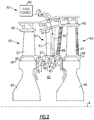
- Figure 2 schematically illustrates providing fluid, such as cooling air, to a vane section 61 in a turbine section 60 of a gas turbine engine, such as a portion of the turbine section 28 of the engine 20 of Figure 1 .
- a turbine section is disclosed as an example, the teachings of this disclosure may also benefit a compressor section.
- the section 60 includes one or more vane sections 61, each having an airfoil section 62 extending between an inner platform 63 and an outer platform 64.
- the vane section 61 may be spaced axially from one or more rotor sections 65.
- the rotor sections 65 may each include a rotor disk 66 carrying one or more blades 67 extending from a platform 68 and for rotation about the engine central longitudinal axis A.
- the rotor sections 65 may include a blade outer air seal 69 ("BOAS”) radially outward of the blades 67.
- BOAS blade outer air seal
- the vane section 61 includes a platform 63 having a forward rail 70 and an aft rail 72 extending inwardly from the platform 63, the example being in the radially inward direction with respect to the engine central longitudinal axis A.
- the platform 63 and rails 70, 72 define a platform cavity 78.
- a fluid source 84 communicates fluid flow F S through the outer platform 64, through an internal channel 86 of the airfoil section 62, through an opening 88 in the platform 63 aligned with the channel 86, and into the platform cavity 78.
- the fluid may then exit the platform cavity 78 through an orifice 83 in a support 80, which is a seal in one non-limiting example, radially inward of the platform 63 and providing a radially inner boundary of the platform cavity 78.
- the fluid may exit through the orifice 83 to the pressurized cavity 85 between adjacent rotor disks 66.
- the outer platform 64 may also benefit from the teachings herein, such as in an arrangement where fluid is provided outwardly through the platform 63, through the channel 86, and through the outer platform 64.
- FIG. 3 schematically illustrates a fluid F S flowing through a portion of an example vane section 161.
- like reference numerals designate like elements where appropriate, and reference numerals with the addition of one-hundred or multiples thereof designate modified elements that are understood to incorporate the same features and benefits of the corresponding original elements.
- a flow diverter 190 (shown schematically) is within the platform cavity 178 and extends radially inwardly from the platform 163.
- the flow diverter 190 defines a diverter cavity 191.
- An inlet 192 provides fluid communication between the opening 188 in the platform 163 and the diverter cavity 191.
- An outlet 193 provides fluid communication between the diverter cavity 191 and the platform cavity 178.
- the flow diverter 190 is configured to receive fluid flow F I in a first direction through the inlet 192 and to expel fluid flow F O in a second, different direction through the outlet 193 and into the platform cavity 178.
- the diverter cavity 191 is provided by the enclosure of the flow diverter 190 inward of the undersurface 176 of the platform 163 and in fluid communication with the channel 186 through the opening 188 in the platform 163.
- the example flow diverter 190 redirects all or a portion of the fluid exiting the opening 188 to be utilized to improve cooling of features of the platform 163 or to improve boundary conditions within the platform cavity 178.
- the cavity 178 is provided by an inner or aft face 173 of the rail 170, an inner or forward face 174 of the rail 172, the undersurface 176 of the platform 163 opposite the airfoil portion 162, and an outer surface 181 of an annular main body portion 182 of the support 180.
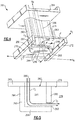
- Figure 4 illustrates an example flow diverter 290 in a vane section 261 configured to receive a fluid flow F I and expel a fluid flow F O .
- the radial direction is defined along the axis A R from the channel 286 to the platform cavity 278.
- the axial direction is defined along the axis A A from a leading edge rail 270 to a trailing edge rail 272.
- the circumferential direction is defined along the axis A C from a pressure side surface P of the platform 263 to a suction side surface S of the platform 263.
- a fluid flow will have a major component in a direction if the directional component of the flow is within 30 degrees of that direction axis.
- a flow having a major component in a radial direction has a radial component within 30 degrees of the axis A R .
- the flow F I has a major component in the radially inward direction
- the fluid flow F O has a major component in a circumferential direction.
- Other directions for F O are contemplated, such as having a major component in the axially aft direction toward the rail 272, a major component in the axially forward direction toward the rail 270, or a major component in the radially outward direction toward the undersurface 276.
- the example flow diverter 290 is provided by a first sidewall 295, a second sidewall 296, a leading edge endwall 297, and a trailing edge endwall 298 extending outwardly from an endcap 294 to the platform 263.
- the endcap 294, first sidewall 295, second sidewall 296, leading edge endwall 297, and trailing edge endwall 298 may be provided by separate components attached to one another or by one or more monolithic pieces.
- the first sidewall 295, the second sidewall 296, the leading edge endwall 297, and the trailing edge endwall 298 form an airfoil-shaped structure complementary to the shape of the airfoil section 262.
- the example outlet 293 is provided in the first sidewall 295, but may alternatively or additionally be provided in the second sidewall 296, the leading edge endwall 297, the trailing edge endwall 298, or the endcap 294.
- the example outlet 293 is an axially elongated slot in the sidewall 295, but other shapes of openings, including but not limited to cylindrical holes, are contemplated.
- Figure 5 schematically illustrates fluid flow through a cross section of the flow diverter 290.
- the inlet 292 receives fluid flow F I , and the outlet 293 expels fluid flow F O .
- the example inlet 292 is defined by the opening where fluid exits the opening 288 and enters the diverter cavity 291.
- the first sidewall 295, the second sidewall 296, the leading edge endwall 297, and the trailing edge endwall 298 extend outwardly from the endcap 294 to the platform undersurface 276 to enclose the diverter cavity 291.
- the endcap 294 radially bounds the diverter cavity 291, the first sidewall 295 and the second sidewall 296 bound the diverter cavity 291 circumferentially, and the leading edge endwall 297 and the trailing edge endwall 298 bound the diverter cavity 291 axially.
- the inlet 292 is provided by the first sidewall 295, the second sidewall 296, the leading edge endwall 297, and the trailing edge endwall 298 and located opposite the diverter cavity 291 from the endcap 294.
- Figure 6 illustrates an example flow diverter 390 providing a first outlet 393A in the first sidewall 395 and a second outlet 393B in the second sidewall 396.
- Each of the outlet 393A and the outlet 393B is an axially elongated slot, and, in one example, the outlet 393A and the outlet 393B have the same elongated length L.
- the outlet 393A is configured to expel fluid having a major component in a circumferential direction
- the outlet 393B is configured to expel fluid having a major component in an opposite circumferential direction.
- the example outlets 393A/393B may expel fluid in a direction having an axially aft component toward the rail 372 as well.
- Figure 7 illustrates an example flow diverter 490 providing a first outlet 493A in the first sidewall 495 and one or more outlets 493B in the leading edge endwall 497.
- the example outlets 493B are cylindrical openings and may provide impingement cooling to the rail 470 in some examples. In some examples, cylindrical openings may alternatively or additionally be provided in the trailing edge endwall 498 to provide impingement cooling to the rail 472.
- Figure 8 illustrates another example flow diverter 590 having a deflecting surface 504 in the diverter cavity 591 for deflecting the fluid flow F I out of the outlet 593 that enters the diverter cavity 591 through the inlet 592.
- the fluid F I flows through the opening 588 and enters the diverter cavity 591 through the inlet 592 in a direction having a major radially inward component.
- the deflecting surface 504 directs the fluid in a direction having a major circumferential component to flow F O out of the outlet 593.
- the flow F O may be in a direction having a major component in the axial direction.
- the example deflecting surface 504 is a concave surface curving toward the outlet 593 as it extends toward the endcap 594. Other sloped surfaces may be utilized.
- the example deflecting surface 504 is provided by a cast part 506 that abuts the sidewall 596 and endcap 594.
- the cast part 506 may be cast as monolithic with the sidewall 596, the endcap 594 or both.
- the deflecting surface 504 may be provided by a sheet metal feature attached to one or both of the sidewall 596 and the endcap 594.
- the deflecting surface 504 may condition fluid flowing across it.
- the deflecting surface 504 is configured to smoothly transition the flow from a first direction to a second direction, reducing turbulent eddies in areas such as corners of the flow diverter cavity 591 that cause high pressure loss.
- Figure 9 illustrates another example flow diverter 690 generally similar to the flow diverter 590, but having two deflecting surfaces 604A/604B for diverting flow out of respective outlets 693A/693B.
- the fluid F I enters the diverter cavity 691 through the inlet 692 in a direction having a major radially inward component, and the deflecting surfaces 604A/604B direct the fluid toward the respective outlets 693A/693B.
- the outlet 693A is configured to expel fluid F OA having a major component in a circumferential direction
- the outlet 693B is configured to expel fluid F OB having a major component in an opposite circumferential direction.
- the flows F OA /F OB are in directions having major components in opposing axial directions.
- the example deflecting surfaces 604A/604B are concave surfaces curving toward their respective outlets 693A/693B as they extend inward toward the endcap 694, but other sloped surfaces may be utilized.
- the example deflecting surfaces 604A/604B are provided by a cast part 606 that abuts the endcap 694.
- the cast part 606 may be cast as monolithic with the endcap 694.
- the surfaces 604A/604B may be provided by sheet metal features attached to the endcap 694.
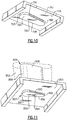
- Figure 10 illustrates an example flow diverter 790 cast as part of the platform 763.
- the first sidewall 795, second sidewall 796, leading edge endwall 797, and trailing edge endwall 798 are monolithic with and extending between the platform undersurface 776 and the endcap 794.
- FIG 11 illustrates another example flow diverter 890 provided by a radially inner portion 807 of a baffle 808.
- a radially outer portion 809 of the baffle 808 is internal to the airfoil section 862.
- the baffle 808 extends through an opening 888 in the platform 863, such that the inner portion 807 is inward of the platform 863 and opposite the platform 863 from the outer portion 809.
- the first sidewall 895, second sidewall 896, leading edge endwall 897, and trailing edge endwall 898 of the flow diverter 890 are provided by inward extensions of the outer walls of the baffle 808 at the inner portion 807.
- An endcap 894 is provided at the inner end of the baffle 808.
- the baffle 808 has a hollow interior (not shown), such that the inner portion 807 provides a diverter cavity in fluid communication with the interior of the outer portion 809.
- Figure 12 illustrates another example flow diverter 990 that is a separate component attached to the undersurface 976 of the platform 963, such as by welding. Other methods for attaching the flow diverter 990 to the undersurface 976 of the platform 963 may be utilized.
- Figure 13 illustrates another example flow diverter 1090 provided by an inner portion 1007 of an insertable component 1008 having an outer portion 1009 configured to be received within the opening 1088 in the platform 1063.
- the outer portion 1009 and inner portion 1007 are hollow (not shown), such that the inner portion 1007 provides a diverter cavity in fluid communication with the interior of the outer portion 1009.
- the outer portion 1009 may be an outward extension of the first sidewall 1095, second sidewall 1096 and leading edge endwall 1097, and trailing edge endwall 1098 and may have a complementary cross sectional shape with the opening 1088.
- FIG 14 illustrates a platform 1163 that may be utilized with one or more example flow diverters disclosed herein. As shown, two openings 1188A and 1188B are provided in the platform 1163 and separated by a rib 1110.
- Figure 15 schematically illustrates an example diverter 1190 positioned to be aligned with one of the openings 1188A/1188B in the platform 1163 shown in Figure 14 .
- the flow diverter 1190 is aligned with the opening 1188B, but opening 1188A is not covered.
- the flow diverter 1190 may be aligned with the opening 1188A.
- a single opening may be provided, and the flow diverter may only partially cover the opening.
- the example diverter 1190 receives a fluid flow portion F SB flowing out of the opening 1188B and into the diverter cavity 1191 (flow shown as F I ).
- the diverter 1190 is not aligned with the opening 1188A, such that a fluid flow portion F SA flowing through the channel 1186 flows directly out of the opening 1188A and into the platform cavity 1178 (flow shown as F D ).
- the fluid flow F D may exit the platform cavity 1178 through an orifice 1183 in the support 1180 inward of the platform 1163.
- Figure 16 schematically illustrates a similar arrangement to that of Figure 15 , except that the channel 1286 is divided into channel parts 1286A and 1286B separated by a partition 1212, and the channel part 1286A receives the fluid flow F SA and the channel part 1286B receives the fluid flow F SB .
- the partition 1212 may be aligned with the rib 1210 between the openings 1288A and 1288B.
Landscapes
- Engineering & Computer Science (AREA)
- Mechanical Engineering (AREA)
- General Engineering & Computer Science (AREA)
- Turbine Rotor Nozzle Sealing (AREA)
- Structures Of Non-Positive Displacement Pumps (AREA)
Abstract
Description
- This disclosure relates to cooling for a component of a gas turbine engine, and more particularly to a flow diverter for diverting flow exiting through a platform of a vane.
- Gas turbine engines can include a fan for propulsion air and to cool components. The fan also delivers air into an engine core where it is compressed. The compressed air is then delivered into a combustion section, where it is mixed with fuel and ignited. The combustion gas expands downstream and drives turbine blades. Static vanes are positioned adjacent to the turbine blades to control the flow of the products of combustion. The blades and vanes are subject to extreme heat, and thus cooling schemes are utilized for each.
- A vane section of a gas turbine engine according to an example of the present disclosure includes a platform and an airfoil extending outwardly from the platform and having an internal channel communicating with an opening in the platform. A rail extends inwardly from the platform, such that a surface of the platform opposite the airfoil and the rail at least partially define a platform cavity. A flow diverter extends inwardly of the platform within the platform cavity and defines a diverter cavity, an inlet configured to receive fluid flowing in a first direction from the opening in the platform to the diverter cavity, and an outlet configured to expel fluid from the diverter cavity to the platform cavity in a second direction different from the first direction.
- In an embodiment according to the foregoing embodiment, the flow diverter includes a plurality of sidewalls, a plurality of endwalls, and an endcap.
- In a further embodiment according to any of the foregoing embodiments, a sloped surface disposed in the diverter cavity is configured to divert fluid from the first direction to the second direction.
- In a further embodiment according to any of the foregoing embodiments, the sloped surface is a concave surface.
- In a further embodiment according to any of the foregoing embodiments, the flow diverter includes a wall extending inwardly from the platform, and the outlet is an opening in the wall.
- In a further embodiment according to any of the foregoing embodiments, a second opening in the platform is configured to provide fluid communication between the channel and the platform cavity.
- In a further embodiment according to any of the foregoing embodiments, a second outlet in the flow diverter is configured to provide fluid communication between the diverter cavity and the platform cavity.
- In a further embodiment according to any of the foregoing embodiments, the second outlet is configured to provide impingement flow on the rail.
- In a further embodiment according to any of the foregoing embodiments, the outlet is a first outlet. The first outlet is defined by an elongated slot, and the second outlet is defined by a cylindrical hole.
- In a further embodiment according to any of the foregoing embodiments, the flow diverter is monolithic with the platform.
- In a further embodiment according to any of the foregoing embodiments, the flow diverter is a separate insert received within the opening in the platform.
- A gas turbine engine according to an example of the present disclosure includes a turbine section.
- A vane within the turbine section includes a platform and an airfoil extending outwardly from the platform and having an internal channel communicating with an opening in the platform. A rail extends from the platform such that a surface of the platform opposite the airfoil and the rail at least partially define a platform cavity. A flow diverter extends inwardly of the platform within the platform cavity and defines a diverter cavity, an inlet configured to receive fluid flowing in a first direction from the opening in the platform to the diverter cavity, and an outlet configured to expel fluid from the diverter cavity to the platform cavity in a second direction different from the first direction.
- In an embodiment according to the foregoing embodiment, a fluid source is configured to provide fluid flow through the internal channel, through the opening in the platform, and to the diverter cavity.
- In a further embodiment according to any of the foregoing embodiments, a sloped surface is disposed in the diverter cavity configured to divert fluid from the first direction to the second direction.
- In a further embodiment according to any of the foregoing embodiments, the flow diverter includes a wall extending inwardly from the platform, and the outlet is an opening in the wall.
- In a further embodiment according to any of the foregoing embodiments, the first direction has a major component in a radially inward direction from the internal channel to the platform cavity, and the second direction has a major component in a circumferential direction between a pressure side surface of the platform and a suction side surface of the platform.
- In a further embodiment according to any of the foregoing embodiments, the first direction has a major component in a radially inward direction from the internal channel to the platform cavity, and the second direction has a major component in an axial direction between a leading edge of the platform and a trailing edge of the platform.
- In a further embodiment according to any of the foregoing embodiments, the platform cavity is bound by a support inward of the platform.
- In a further embodiment according to any of the foregoing embodiments, a rotor section is axially spaced from the vane section with respect to an engine central longitudinal axis. The support includes an orifice configured to provide fluid communication between the platform cavity and a pressurized cavity provided at least partially by the rotor section.
- In a further embodiment according to any of the foregoing embodiments, the flow diverter includes a plurality of sidewalls, a plurality of endwalls, and an endcap, and the outlet is provided by an opening in one of the plurality of sidewalls.
- These and other features disclosed herein can be best understood from the following specification and drawings, the following of which is a brief description.
-
-
Figure 1 schematically illustrates an example gas turbine engine. -
Figure 2 shows an example section of a gas turbine engine. -
Figure 3 schematically illustrates a fluid flow through a portion of another example section of a gas turbine engine. -
Figure 4 illustrates an example flow diverter. -
Figure 5 schematically illustrates a flow a cross sectional view of the example flow diverter ofFigure 4 . -
Figure 6 illustrates another example flow diverter. -
Figure 7 illustrates another example flow diverter. -
Figure 8 schematically illustrates a flow through a cross sectional view of another example flow diverter. -
Figure 9 schematically illustrates a flow through a cross sectional view of another example flow diverter. -
Figure 10 illustrates another example flow diverter. -
Figure 11 illustrates another example flow diverter. -
Figure 12 illustrates another example flow diverter. -
Figure 13 illustrates another example flow diverter. -
Figure 14 illustrates an example platform. -
Figure 15 schematically illustrates an example fluid flow scheme utilizing the example platform ofFigure 14 . -
Figure 16 schematically illustrates another example fluid flow scheme utilizing the example platform ofFigure 14 . -
Figure 1 schematically illustrates agas turbine engine 20. Thegas turbine engine 20 is disclosed herein as a two-spool turbofan that generally incorporates afan section 22, acompressor section 24, acombustor section 26 and aturbine section 28. Alternative engines might include an augmentor section (not shown) among other systems or features. Thefan section 22 drives air along a bypass flow path B in a bypass duct defined within anacelle 18, and also drives air along a core flow path C for compression and communication into thecombustor section 26 then expansion through theturbine section 28. Although depicted as a two-spool turbofan gas turbine engine in the disclosed non-limiting embodiment, it should be understood that the concepts described herein are not limited to use with two-spool turbofans as the teachings may be applied to other types of turbine engines including three-spool architectures. - The
exemplary engine 20 generally includes alow speed spool 30 and ahigh speed spool 32 mounted for rotation about an engine central longitudinal axis A relative to an enginestatic structure 36 viaseveral bearing systems 38. It should be understood thatvarious bearing systems 38 at various locations may alternatively or additionally be provided, and the location ofbearing systems 38 may be varied as appropriate to the application. - The
low speed spool 30 generally includes aninner shaft 40 that interconnects afan 42, a first (or low)pressure compressor 44 and a first (or low)pressure turbine 46. Theinner shaft 40 is connected to thefan 42 through a speed change mechanism, which in exemplarygas turbine engine 20 is illustrated as a gearedarchitecture 48 to drive thefan 42 at a lower speed than thelow speed spool 30. Thehigh speed spool 32 includes anouter shaft 50 that interconnects a second (or high)pressure compressor 52 and a second (or high) pressure turbine 54. Acombustor 56 is arranged inexemplary gas turbine 20 between thehigh pressure compressor 52 and the high pressure turbine 54. A mid-turbine frame 57 of the enginestatic structure 36 is arranged generally between the high pressure turbine 54 and thelow pressure turbine 46. The mid-turbine frame 57 furthersupports bearing systems 38 in theturbine section 28. Theinner shaft 40 and theouter shaft 50 are concentric and rotate via bearingsystems 38 about the engine central longitudinal axis A which is collinear with their longitudinal axes. - The core airflow is compressed by the
low pressure compressor 44 then thehigh pressure compressor 52, mixed and burned with fuel in thecombustor 56, then expanded over the high pressure turbine 54 andlow pressure turbine 46. The mid-turbine frame 57 includes airfoils 59 which are in the core airflow path C. Theturbines 46, 54 rotationally drive the respectivelow speed spool 30 andhigh speed spool 32 in response to the expansion. It will be appreciated that each of the positions of thefan section 22,compressor section 24,combustor section 26,turbine section 28, and fandrive gear system 48 may be varied. For example,gear system 48 may be located aft ofcombustor section 26 or even aft ofturbine section 28, andfan section 22 may be positioned forward or aft of the location ofgear system 48. - The
engine 20 in one example is a high-bypass geared aircraft engine. In a further example, theengine 20 bypass ratio is greater than about six (6), with an example embodiment being greater than about ten (10), the gearedarchitecture 48 is an epicyclic gear train, such as a planetary gear system or other gear system, with a gear reduction ratio of greater than about 2.3 and thelow pressure turbine 46 has a pressure ratio that is greater than about five. In one disclosed embodiment, theengine 20 bypass ratio is greater than about ten (10:1), the fan diameter is significantly larger than that of thelow pressure compressor 44, and thelow pressure turbine 46 has a pressure ratio that is greater than about five 5:1.Low pressure turbine 46 pressure ratio is pressure measured prior to inlet oflow pressure turbine 46 as related to the pressure at the outlet of thelow pressure turbine 46 prior to an exhaust nozzle. The gearedarchitecture 48 may be an epicycle gear train, such as a planetary gear system or other gear system, with a gear reduction ratio of greater than about 2.3:1. It should be understood, however, that the above parameters are only exemplary of one embodiment of a geared architecture engine and that the present invention is applicable to other gas turbine engines including direct drive turbofans. - A significant amount of thrust is provided by the bypass flow B due to the high bypass ratio. The
fan section 22 of theengine 20 is designed for a particular flight condition -- typically cruise at about 0.8 Mach and about 35,000 feet (10,668 meters). The flight condition of 0.8 Mach and 35,000 ft (10,668 meters), with the engine at its best fuel consumption - also known as "bucket cruise Thrust Specific Fuel Consumption ('TSFC')" - is the industry standard parameter of lbm of fuel being burned divided by lbf of thrust the engine produces at that minimum point. "Low fan pressure ratio" is the pressure ratio across the fan blade alone, without a Fan Exit Guide Vane ("FEGV") system. The low fan pressure ratio as disclosed herein according to one non-limiting embodiment is less than about 1.45. "Low corrected fan tip speed" is the actual fan tip speed in ft/sec divided by an industry standard temperature correction read [(Tram °R) / (518.7 °R)]^0.5 (where R = K x 9/5). The "Low corrected fan tip speed" as disclosed herein according to one non-limiting embodiment is less than about 1150 ft / second (350.5 meters/second). -
Figure 2 schematically illustrates providing fluid, such as cooling air, to avane section 61 in aturbine section 60 of a gas turbine engine, such as a portion of theturbine section 28 of theengine 20 ofFigure 1 . Although a turbine section is disclosed as an example, the teachings of this disclosure may also benefit a compressor section. In this example, thesection 60 includes one ormore vane sections 61, each having anairfoil section 62 extending between aninner platform 63 and anouter platform 64. Thevane section 61 may be spaced axially from one ormore rotor sections 65. Therotor sections 65 may each include arotor disk 66 carrying one ormore blades 67 extending from aplatform 68 and for rotation about the engine central longitudinal axis A. Therotor sections 65 may include a blade outer air seal 69 ("BOAS") radially outward of theblades 67. - The
vane section 61 includes aplatform 63 having aforward rail 70 and anaft rail 72 extending inwardly from theplatform 63, the example being in the radially inward direction with respect to the engine central longitudinal axis A. Theplatform 63 and rails 70, 72 define aplatform cavity 78. Afluid source 84 communicates fluid flow FS through theouter platform 64, through aninternal channel 86 of theairfoil section 62, through anopening 88 in theplatform 63 aligned with thechannel 86, and into theplatform cavity 78. In the example, the fluid may then exit theplatform cavity 78 through anorifice 83 in asupport 80, which is a seal in one non-limiting example, radially inward of theplatform 63 and providing a radially inner boundary of theplatform cavity 78. The fluid may exit through theorifice 83 to thepressurized cavity 85 betweenadjacent rotor disks 66. Although examples in this disclosure are directed to theinner platform 63, theouter platform 64 may also benefit from the teachings herein, such as in an arrangement where fluid is provided outwardly through theplatform 63, through thechannel 86, and through theouter platform 64. -
Figure 3 schematically illustrates a fluid FS flowing through a portion of anexample vane section 161. In this disclosure, like reference numerals designate like elements where appropriate, and reference numerals with the addition of one-hundred or multiples thereof designate modified elements that are understood to incorporate the same features and benefits of the corresponding original elements. A flow diverter 190 (shown schematically) is within theplatform cavity 178 and extends radially inwardly from theplatform 163. Theflow diverter 190 defines adiverter cavity 191. Aninlet 192 provides fluid communication between the opening 188 in theplatform 163 and thediverter cavity 191. Anoutlet 193 provides fluid communication between thediverter cavity 191 and theplatform cavity 178. Theflow diverter 190 is configured to receive fluid flow FI in a first direction through theinlet 192 and to expel fluid flow FO in a second, different direction through theoutlet 193 and into theplatform cavity 178. Thediverter cavity 191 is provided by the enclosure of theflow diverter 190 inward of the undersurface 176 of theplatform 163 and in fluid communication with thechannel 186 through theopening 188 in theplatform 163. Theexample flow diverter 190 redirects all or a portion of the fluid exiting theopening 188 to be utilized to improve cooling of features of theplatform 163 or to improve boundary conditions within theplatform cavity 178. Thecavity 178 is provided by an inner oraft face 173 of therail 170, an inner orforward face 174 of therail 172, the undersurface 176 of theplatform 163 opposite theairfoil portion 162, and anouter surface 181 of an annularmain body portion 182 of thesupport 180. -
Figure 4 illustrates anexample flow diverter 290 in avane section 261 configured to receive a fluid flow FI and expel a fluid flow FO. In the examples herein, the radial direction is defined along the axis AR from thechannel 286 to theplatform cavity 278. The axial direction is defined along the axis AA from aleading edge rail 270 to a trailingedge rail 272. The circumferential direction is defined along the axis AC from a pressure side surface P of theplatform 263 to a suction side surface S of theplatform 263. As used herein, a fluid flow will have a major component in a direction if the directional component of the flow is within 30 degrees of that direction axis. For example, a flow having a major component in a radial direction has a radial component within 30 degrees of the axis AR. In the example, the flow FI has a major component in the radially inward direction, and the fluid flow FO has a major component in a circumferential direction. Other directions for FO are contemplated, such as having a major component in the axially aft direction toward therail 272, a major component in the axially forward direction toward therail 270, or a major component in the radially outward direction toward theundersurface 276. - The
example flow diverter 290 is provided by afirst sidewall 295, asecond sidewall 296, aleading edge endwall 297, and a trailingedge endwall 298 extending outwardly from anendcap 294 to theplatform 263. Theendcap 294,first sidewall 295,second sidewall 296, leadingedge endwall 297, and trailingedge endwall 298 may be provided by separate components attached to one another or by one or more monolithic pieces. In some examples, thefirst sidewall 295, thesecond sidewall 296, theleading edge endwall 297, and the trailingedge endwall 298 form an airfoil-shaped structure complementary to the shape of theairfoil section 262. Theexample outlet 293 is provided in thefirst sidewall 295, but may alternatively or additionally be provided in thesecond sidewall 296, theleading edge endwall 297, the trailingedge endwall 298, or theendcap 294. Theexample outlet 293 is an axially elongated slot in thesidewall 295, but other shapes of openings, including but not limited to cylindrical holes, are contemplated. -
Figure 5 schematically illustrates fluid flow through a cross section of theflow diverter 290. Theinlet 292 receives fluid flow FI, and theoutlet 293 expels fluid flow FO. Theexample inlet 292 is defined by the opening where fluid exits theopening 288 and enters thediverter cavity 291. - Returning to
Figure 4 , with continued reference toFigure 5 , in the example, thefirst sidewall 295, thesecond sidewall 296, theleading edge endwall 297, and the trailingedge endwall 298 extend outwardly from theendcap 294 to theplatform undersurface 276 to enclose thediverter cavity 291. Theendcap 294 radially bounds thediverter cavity 291, thefirst sidewall 295 and thesecond sidewall 296 bound thediverter cavity 291 circumferentially, and theleading edge endwall 297 and the trailingedge endwall 298 bound thediverter cavity 291 axially. Theinlet 292 is provided by thefirst sidewall 295, thesecond sidewall 296, theleading edge endwall 297, and the trailingedge endwall 298 and located opposite thediverter cavity 291 from theendcap 294. -
Figure 6 illustrates anexample flow diverter 390 providing afirst outlet 393A in thefirst sidewall 395 and asecond outlet 393B in thesecond sidewall 396. Each of theoutlet 393A and theoutlet 393B is an axially elongated slot, and, in one example, theoutlet 393A and theoutlet 393B have the same elongated length L. Theoutlet 393A is configured to expel fluid having a major component in a circumferential direction, and theoutlet 393B is configured to expel fluid having a major component in an opposite circumferential direction. Theexample outlets 393A/393B may expel fluid in a direction having an axially aft component toward therail 372 as well. -
Figure 7 illustrates anexample flow diverter 490 providing afirst outlet 493A in thefirst sidewall 495 and one ormore outlets 493B in theleading edge endwall 497. Theexample outlets 493B are cylindrical openings and may provide impingement cooling to therail 470 in some examples. In some examples, cylindrical openings may alternatively or additionally be provided in the trailingedge endwall 498 to provide impingement cooling to the rail 472. -
Figure 8 illustrates anotherexample flow diverter 590 having a deflectingsurface 504 in thediverter cavity 591 for deflecting the fluid flow FI out of theoutlet 593 that enters thediverter cavity 591 through theinlet 592. In the example, the fluid FI flows through theopening 588 and enters thediverter cavity 591 through theinlet 592 in a direction having a major radially inward component. The deflectingsurface 504 directs the fluid in a direction having a major circumferential component to flow FO out of theoutlet 593. In another example, the flow FO may be in a direction having a major component in the axial direction. - The
example deflecting surface 504 is a concave surface curving toward theoutlet 593 as it extends toward theendcap 594. Other sloped surfaces may be utilized. Theexample deflecting surface 504 is provided by acast part 506 that abuts thesidewall 596 andendcap 594. Alternatively, thecast part 506 may be cast as monolithic with thesidewall 596, theendcap 594 or both. In another example, the deflectingsurface 504 may be provided by a sheet metal feature attached to one or both of thesidewall 596 and theendcap 594. The deflectingsurface 504 may condition fluid flowing across it. The deflectingsurface 504 is configured to smoothly transition the flow from a first direction to a second direction, reducing turbulent eddies in areas such as corners of theflow diverter cavity 591 that cause high pressure loss. -
Figure 9 illustrates anotherexample flow diverter 690 generally similar to theflow diverter 590, but having two deflectingsurfaces 604A/604B for diverting flow out ofrespective outlets 693A/693B. In the example, the fluid FI enters thediverter cavity 691 through theinlet 692 in a direction having a major radially inward component, and the deflecting surfaces 604A/604B direct the fluid toward therespective outlets 693A/693B. Theoutlet 693A is configured to expel fluid FOA having a major component in a circumferential direction, and theoutlet 693B is configured to expel fluid FOB having a major component in an opposite circumferential direction. In another example, the flows FOA/FOB are in directions having major components in opposing axial directions. - The example deflecting surfaces 604A/604B are concave surfaces curving toward their
respective outlets 693A/693B as they extend inward toward theendcap 694, but other sloped surfaces may be utilized. The example deflecting surfaces 604A/604B are provided by acast part 606 that abuts theendcap 694. Alternatively, thecast part 606 may be cast as monolithic with theendcap 694. In another example, thesurfaces 604A/604B may be provided by sheet metal features attached to theendcap 694. -
Figure 10 illustrates anexample flow diverter 790 cast as part of theplatform 763. Thefirst sidewall 795,second sidewall 796, leadingedge endwall 797, and trailingedge endwall 798 are monolithic with and extending between theplatform undersurface 776 and theendcap 794. -
Figure 11 illustrates anotherexample flow diverter 890 provided by a radiallyinner portion 807 of abaffle 808. A radiallyouter portion 809 of thebaffle 808 is internal to theairfoil section 862. Thebaffle 808 extends through anopening 888 in theplatform 863, such that theinner portion 807 is inward of theplatform 863 and opposite theplatform 863 from theouter portion 809. Thefirst sidewall 895,second sidewall 896, leadingedge endwall 897, and trailing edge endwall 898 of theflow diverter 890 are provided by inward extensions of the outer walls of thebaffle 808 at theinner portion 807. Anendcap 894 is provided at the inner end of thebaffle 808. Thebaffle 808 has a hollow interior (not shown), such that theinner portion 807 provides a diverter cavity in fluid communication with the interior of theouter portion 809. -
Figure 12 illustrates anotherexample flow diverter 990 that is a separate component attached to theundersurface 976 of theplatform 963, such as by welding. Other methods for attaching theflow diverter 990 to theundersurface 976 of theplatform 963 may be utilized. -
Figure 13 illustrates another example flow diverter 1090 provided by aninner portion 1007 of aninsertable component 1008 having anouter portion 1009 configured to be received within theopening 1088 in theplatform 1063. Theouter portion 1009 andinner portion 1007 are hollow (not shown), such that theinner portion 1007 provides a diverter cavity in fluid communication with the interior of theouter portion 1009. Theouter portion 1009 may be an outward extension of thefirst sidewall 1095,second sidewall 1096 and leadingedge endwall 1097, and trailing edge endwall 1098 and may have a complementary cross sectional shape with theopening 1088. -
Figure 14 illustrates aplatform 1163 that may be utilized with one or more example flow diverters disclosed herein. As shown, twoopenings platform 1163 and separated by arib 1110. -
Figure 15 schematically illustrates anexample diverter 1190 positioned to be aligned with one of theopenings 1188A/1188B in theplatform 1163 shown inFigure 14 . In the example shown, theflow diverter 1190 is aligned with theopening 1188B, butopening 1188A is not covered. Alternatively, theflow diverter 1190 may be aligned with theopening 1188A. As another alternative, a single opening may be provided, and the flow diverter may only partially cover the opening. Theexample diverter 1190 receives a fluid flow portion FSB flowing out of theopening 1188B and into the diverter cavity 1191 (flow shown as FI). Thediverter 1190 is not aligned with theopening 1188A, such that a fluid flow portion FSA flowing through thechannel 1186 flows directly out of theopening 1188A and into the platform cavity 1178 (flow shown as FD). In some examples, the fluid flow FD may exit theplatform cavity 1178 through anorifice 1183 in thesupport 1180 inward of theplatform 1163. -
Figure 16 schematically illustrates a similar arrangement to that ofFigure 15 , except that the channel 1286 is divided intochannel parts partition 1212, and thechannel part 1286A receives the fluid flow FSA and thechannel part 1286B receives the fluid flow FSB. Thepartition 1212 may be aligned with therib 1210 between theopenings - It should be understood that relative positional terms such as "forward," "aft," "upper," "lower," "above," "below," and the like are with reference to the normal operational attitude of the vehicle and should not be considered otherwise limiting.
- Although the different examples have the specific components or features shown in the illustrations, embodiments of this disclosure are not limited to those particular combinations. It is possible to use some of the components or features from one of the examples in combination with features or components from another one of the examples.
- One of ordinary skill in this art would understand that the above-described embodiments are exemplary and non-limiting. That is, modifications of this disclosure would come within the scope of the claims. Accordingly, the following claims should be studied to determine their true scope and content.
Claims (15)
- A vane section (161) of a gas turbine engine (20) comprising:a platform (163);an airfoil (162) extending outwardly from the platform (163) and having an internal channel (186) communicating with an opening (188) in the platform (163);at least one rail (170, 172) extending inwardly from the platform (163) such that a surface of the platform (163) opposite the airfoil (162) and the at least one rail (170, 172) at least partially define a platform cavity (178);a flow diverter (190) extending inwardly of the platform (163) within the platform cavity (178) and defining a diverter cavity (191), an inlet (192) configured to receive fluid (FI) flowing in a first direction from the opening (188) in the platform (163) to the diverter cavity (191), and an outlet (193) configured to expel fluid (FO) from the diverter cavity (191) to the platform cavity (178) in a second direction different from the first direction.
- The vane section (161) as recited in claim 1, wherein the flow diverter (190) includes a plurality of sidewalls (295, 296), a plurality of endwalls (297, 298), and an endcap (294).
- The vane section (161) as recited in claim 2, wherein the outlet (193) is provided by an opening in one of the plurality of sidewalls (295, 296).
- The vane section (161) as recited in claim 1, 2 or 3, comprising a sloped surface (504, 604) disposed in the diverter cavity (191) configured to divert fluid from the first direction to the second direction, wherein, optionally, the sloped surface (504, 604) is a concave surface.
- The vane section (161) as recited in claim 1, wherein the flow diverter (191) includes a wall (295, 296, 297, 298) extending inwardly from the platform (163), and the outlet (193) is an opening in the wall (295, 296, 297, 298).
- The vane section (161) as recited in any preceding claim, comprising a second opening (1188A) in the platform (163) configured to provide fluid communication between the channel (186) and the platform cavity (178).
- The vane section (161) as recited in any preceding claim, comprising a second outlet (493B) in the flow diverter (190) configured to provide fluid communication between the diverter cavity (191) and the platform cavity (178).
- The vane section (161) as recited in claim 7, wherein the second outlet (493B) is configured to provide impingement flow on the at least one rail (70, 72).
- The vane section (161) as recited in claim 7 or 8, wherein the outlet (193) is a first outlet, the first outlet is defined by an elongated slot, and the second outlet (493B) is defined by a cylindrical hole.
- The vane section (161) as recited in any preceding claim, wherein:the flow diverter (191) is monolithic with the platform (163) orthe flow diverter (191) is a separate insert received within the opening (188) in the platform (163).
- A gas turbine engine (20), comprising:a turbine section (28); andat least one vane section (161) of any preceding claim within the turbine section (28).
- The gas turbine engine (20) as recited in claim 11, comprising a fluid source (84) configured to provide fluid flow (FS) through the internal channel (186), through the opening (188) in the platform (163), and to the diverter cavity (191).
- The gas turbine engine (20) as recited in claim 11 or 12, wherein the first direction has a major component in a radially inward direction from the internal channel (186) to the platform cavity (178), and the second direction has a major component either in a circumferential direction between a pressure side surface of the platform (163) and a suction side surface of the platform (163), or in an axial direction between a leading edge of the platform (163) and a trailing edge of the platform (163).
- The gas turbine engine (20) as recited in claim 11, 12 or 13, wherein the platform cavity (178) is bound by a support (180) inward of the platform (163).
- The gas turbine engine (20) as recited in claim 14, comprising:
a rotor section (65) axially spaced from the vane section (161) with respect to an engine central longitudinal axis (A), wherein the support (180) includes an orifice (83) configured to provide fluid communication between the platform cavity (178) and a pressurized cavity (85) provided at least partially by the rotor section (65).
Applications Claiming Priority (1)
| Application Number | Priority Date | Filing Date | Title |
|---|---|---|---|
| US15/884,494 US20190234235A1 (en) | 2018-01-31 | 2018-01-31 | Vane flow diverter |
Publications (2)
| Publication Number | Publication Date |
|---|---|
| EP3527783A1 true EP3527783A1 (en) | 2019-08-21 |
| EP3527783B1 EP3527783B1 (en) | 2024-04-10 |
Family
ID=65243443
Family Applications (1)
| Application Number | Title | Priority Date | Filing Date |
|---|---|---|---|
| EP19154299.2A Active EP3527783B1 (en) | 2018-01-31 | 2019-01-29 | Vane flow diverter |
Country Status (2)
| Country | Link |
|---|---|
| US (1) | US20190234235A1 (en) |
| EP (1) | EP3527783B1 (en) |
Cited By (2)
| Publication number | Priority date | Publication date | Assignee | Title |
|---|---|---|---|---|
| EP3819465A1 (en) * | 2019-11-08 | 2021-05-12 | Raytheon Technologies Corporation | Ceramic airfoil with cooling air turn |
| EP3862539A1 (en) * | 2020-02-07 | 2021-08-11 | Raytheon Technologies Corporation | Flow diverter for mid-turbine frame cooling air delivery |
Families Citing this family (5)
| Publication number | Priority date | Publication date | Assignee | Title |
|---|---|---|---|---|
| US10787932B2 (en) * | 2018-07-13 | 2020-09-29 | Honeywell International Inc. | Turbine blade with dust tolerant cooling system |
| US10982546B2 (en) * | 2018-09-19 | 2021-04-20 | General Electric Company | Flow-diverting systems for gas turbine air separator |
| USD984255S1 (en) * | 2020-06-18 | 2023-04-25 | Pexco Aerospace, Inc. | Air redirector mount |
| US20220316352A1 (en) * | 2021-03-31 | 2022-10-06 | Raytheon Technologies Corporation | Flow diverter for mid-turbine frame cooling air delivery |
| JP2023172520A (en) * | 2022-05-24 | 2023-12-06 | 三菱重工業株式会社 | Turbine vanes and gas turbines |
Citations (6)
| Publication number | Priority date | Publication date | Assignee | Title |
|---|---|---|---|---|
| US5488825A (en) * | 1994-10-31 | 1996-02-06 | Westinghouse Electric Corporation | Gas turbine vane with enhanced cooling |
| US6126389A (en) * | 1998-09-02 | 2000-10-03 | General Electric Co. | Impingement cooling for the shroud of a gas turbine |
| EP1219784A2 (en) * | 2000-12-28 | 2002-07-03 | General Electric Company | Apparatus and method for localized cooling of gas turbine nozzle walls |
| WO2015030926A1 (en) * | 2013-08-30 | 2015-03-05 | United Technologies Corporation | Baffle for gas turbine engine vane |
| EP3130756A1 (en) * | 2015-08-12 | 2017-02-15 | United Technologies Corporation | Low turn loss baffle flow diverter |
| EP3228817A2 (en) * | 2016-04-06 | 2017-10-11 | General Electric Company | Air bypass system for rotor shaft cooling |
Family Cites Families (9)
| Publication number | Priority date | Publication date | Assignee | Title |
|---|---|---|---|---|
| US6065928A (en) * | 1998-07-22 | 2000-05-23 | General Electric Company | Turbine nozzle having purge air circuit |
| US6769865B2 (en) * | 2002-03-22 | 2004-08-03 | General Electric Company | Band cooled turbine nozzle |
| US8016547B2 (en) * | 2008-01-22 | 2011-09-13 | United Technologies Corporation | Radial inner diameter metering plate |
| EP2392775A1 (en) * | 2010-06-07 | 2011-12-07 | Siemens Aktiengesellschaft | Blade for use in a fluid flow of a turbine engine and turbine engine |
| US9476429B2 (en) * | 2012-12-19 | 2016-10-25 | United Technologies Corporation | Flow feed diffuser |
| GB201408543D0 (en) * | 2014-05-14 | 2014-06-25 | Rolls Royce Plc | Distributor device for cooling air within an engine |
| EP2990607A1 (en) * | 2014-08-28 | 2016-03-02 | Siemens Aktiengesellschaft | Cooling concept for turbine blades or vanes |
| US9926799B2 (en) * | 2015-10-12 | 2018-03-27 | United Technologies Corporation | Gas turbine engine components, blade outer air seal assemblies, and blade outer air seal segments thereof |
| US10415428B2 (en) * | 2018-01-31 | 2019-09-17 | United Technologies Corporation | Dual cavity baffle |
-
2018
- 2018-01-31 US US15/884,494 patent/US20190234235A1/en not_active Abandoned
-
2019
- 2019-01-29 EP EP19154299.2A patent/EP3527783B1/en active Active
Patent Citations (6)
| Publication number | Priority date | Publication date | Assignee | Title |
|---|---|---|---|---|
| US5488825A (en) * | 1994-10-31 | 1996-02-06 | Westinghouse Electric Corporation | Gas turbine vane with enhanced cooling |
| US6126389A (en) * | 1998-09-02 | 2000-10-03 | General Electric Co. | Impingement cooling for the shroud of a gas turbine |
| EP1219784A2 (en) * | 2000-12-28 | 2002-07-03 | General Electric Company | Apparatus and method for localized cooling of gas turbine nozzle walls |
| WO2015030926A1 (en) * | 2013-08-30 | 2015-03-05 | United Technologies Corporation | Baffle for gas turbine engine vane |
| EP3130756A1 (en) * | 2015-08-12 | 2017-02-15 | United Technologies Corporation | Low turn loss baffle flow diverter |
| EP3228817A2 (en) * | 2016-04-06 | 2017-10-11 | General Electric Company | Air bypass system for rotor shaft cooling |
Cited By (4)
| Publication number | Priority date | Publication date | Assignee | Title |
|---|---|---|---|---|
| EP3819465A1 (en) * | 2019-11-08 | 2021-05-12 | Raytheon Technologies Corporation | Ceramic airfoil with cooling air turn |
| US11473444B2 (en) | 2019-11-08 | 2022-10-18 | Raytheon Technologies Corporation | Ceramic airfoil with cooling air turn |
| EP3862539A1 (en) * | 2020-02-07 | 2021-08-11 | Raytheon Technologies Corporation | Flow diverter for mid-turbine frame cooling air delivery |
| US11698005B2 (en) | 2020-02-07 | 2023-07-11 | Raytheon Technologies Corporation | Flow diverter for mid-turbine frame cooling air delivery |
Also Published As
| Publication number | Publication date |
|---|---|
| EP3527783B1 (en) | 2024-04-10 |
| US20190234235A1 (en) | 2019-08-01 |
Similar Documents
| Publication | Publication Date | Title |
|---|---|---|
| EP3527783B1 (en) | Vane flow diverter | |
| EP3543464B1 (en) | Dual cavity baffle | |
| US11035236B2 (en) | Baffle for a component of a gas turbine engine | |
| EP3004558B1 (en) | Gas turbine engine airfoil trailing edge suction side cooling | |
| US20180283185A1 (en) | Low turn loss baffle flow diverter | |
| EP3783197B1 (en) | Airfoil with rib having connector arms | |
| EP3061910B1 (en) | Gas turbine engine airfoil and corresponding method of forming | |
| EP3650655B1 (en) | Airfoil, corresponding gas turbine engine and method for assembling | |
| EP3150800B1 (en) | Airfoil baffle with wedge region | |
| EP3324000B1 (en) | Airfoil and corresponding gas turbine engine | |
| US20200263563A1 (en) | Platform lip impingement features | |
| EP3495614B1 (en) | Cooled gas turbine engine component | |
| EP3650646B1 (en) | Airfoil with baffle showerhead and cooling passage network having aft inlet | |
| EP3623587B1 (en) | Airfoil assembly for a gas turbine engine | |
| EP3556996B1 (en) | Blade with inlet orifice on forward face of root | |
| EP3556997B1 (en) | Blade with inlet orifice on aft face of root | |
| EP3650641B1 (en) | Airfoil with cooling passage circuit through platforms and airfoil section | |
| EP3581762B1 (en) | Platform cooling arrangement for a gas turbine engine | |
| EP2977557B1 (en) | Cooled airfoil structure and corresponding cooling method | |
| EP2942486B1 (en) | Gas turbine engine airfoil cooling passage configuration | |
| EP3502417B1 (en) | Platform flow turning elements for gas turbine engine components | |
| EP3324004B1 (en) | Airfoil with retention pocket holding airfoil piece |
Legal Events
| Date | Code | Title | Description |
|---|---|---|---|
| PUAI | Public reference made under article 153(3) epc to a published international application that has entered the european phase |
Free format text: ORIGINAL CODE: 0009012 |
|
| STAA | Information on the status of an ep patent application or granted ep patent |
Free format text: STATUS: THE APPLICATION HAS BEEN PUBLISHED |
|
| AK | Designated contracting states |
Kind code of ref document: A1 Designated state(s): AL AT BE BG CH CY CZ DE DK EE ES FI FR GB GR HR HU IE IS IT LI LT LU LV MC MK MT NL NO PL PT RO RS SE SI SK SM TR |
|
| AX | Request for extension of the european patent |
Extension state: BA ME |
|
| STAA | Information on the status of an ep patent application or granted ep patent |
Free format text: STATUS: REQUEST FOR EXAMINATION WAS MADE |
|
| 17P | Request for examination filed |
Effective date: 20200220 |
|
| RBV | Designated contracting states (corrected) |
Designated state(s): AL AT BE BG CH CY CZ DE DK EE ES FI FR GB GR HR HU IE IS IT LI LT LU LV MC MK MT NL NO PL PT RO RS SE SI SK SM TR |
|
| STAA | Information on the status of an ep patent application or granted ep patent |
Free format text: STATUS: EXAMINATION IS IN PROGRESS |
|
| 17Q | First examination report despatched |
Effective date: 20200709 |
|
| RAP1 | Party data changed (applicant data changed or rights of an application transferred) |
Owner name: RAYTHEON TECHNOLOGIES CORPORATION |
|
| GRAP | Despatch of communication of intention to grant a patent |
Free format text: ORIGINAL CODE: EPIDOSNIGR1 |
|
| STAA | Information on the status of an ep patent application or granted ep patent |
Free format text: STATUS: GRANT OF PATENT IS INTENDED |
|
| INTG | Intention to grant announced |
Effective date: 20230523 |
|
| GRAJ | Information related to disapproval of communication of intention to grant by the applicant or resumption of examination proceedings by the epo deleted |
Free format text: ORIGINAL CODE: EPIDOSDIGR1 |
|
| STAA | Information on the status of an ep patent application or granted ep patent |
Free format text: STATUS: EXAMINATION IS IN PROGRESS |
|
| INTC | Intention to grant announced (deleted) | ||
| GRAP | Despatch of communication of intention to grant a patent |
Free format text: ORIGINAL CODE: EPIDOSNIGR1 |
|
| STAA | Information on the status of an ep patent application or granted ep patent |
Free format text: STATUS: GRANT OF PATENT IS INTENDED |
|
| RAP3 | Party data changed (applicant data changed or rights of an application transferred) |
Owner name: RTX CORPORATION |
|
| INTG | Intention to grant announced |
Effective date: 20231026 |
|
| GRAS | Grant fee paid |
Free format text: ORIGINAL CODE: EPIDOSNIGR3 |
|
| GRAA | (expected) grant |
Free format text: ORIGINAL CODE: 0009210 |
|
| STAA | Information on the status of an ep patent application or granted ep patent |
Free format text: STATUS: THE PATENT HAS BEEN GRANTED |
|
| AK | Designated contracting states |
Kind code of ref document: B1 Designated state(s): AL AT BE BG CH CY CZ DE DK EE ES FI FR GB GR HR HU IE IS IT LI LT LU LV MC MK MT NL NO PL PT RO RS SE SI SK SM TR |
|
| REG | Reference to a national code |
Ref country code: GB Ref legal event code: FG4D |
|
| REG | Reference to a national code |
Ref country code: CH Ref legal event code: EP |
|
| REG | Reference to a national code |
Ref country code: DE Ref legal event code: R096 Ref document number: 602019049841 Country of ref document: DE |
|
| REG | Reference to a national code |
Ref country code: IE Ref legal event code: FG4D |
|
| REG | Reference to a national code |
Ref country code: LT Ref legal event code: MG9D |
|
| REG | Reference to a national code |
Ref country code: NL Ref legal event code: MP Effective date: 20240410 |
|
| REG | Reference to a national code |
Ref country code: AT Ref legal event code: MK05 Ref document number: 1675097 Country of ref document: AT Kind code of ref document: T Effective date: 20240410 |
|
| PG25 | Lapsed in a contracting state [announced via postgrant information from national office to epo] |
Ref country code: NL Free format text: LAPSE BECAUSE OF FAILURE TO SUBMIT A TRANSLATION OF THE DESCRIPTION OR TO PAY THE FEE WITHIN THE PRESCRIBED TIME-LIMIT Effective date: 20240410 |
|
| PG25 | Lapsed in a contracting state [announced via postgrant information from national office to epo] |
Ref country code: NL Free format text: LAPSE BECAUSE OF FAILURE TO SUBMIT A TRANSLATION OF THE DESCRIPTION OR TO PAY THE FEE WITHIN THE PRESCRIBED TIME-LIMIT Effective date: 20240410 |
|
| PG25 | Lapsed in a contracting state [announced via postgrant information from national office to epo] |
Ref country code: IS Free format text: LAPSE BECAUSE OF FAILURE TO SUBMIT A TRANSLATION OF THE DESCRIPTION OR TO PAY THE FEE WITHIN THE PRESCRIBED TIME-LIMIT Effective date: 20240810 |
|
| PG25 | Lapsed in a contracting state [announced via postgrant information from national office to epo] |
Ref country code: BG Free format text: LAPSE BECAUSE OF FAILURE TO SUBMIT A TRANSLATION OF THE DESCRIPTION OR TO PAY THE FEE WITHIN THE PRESCRIBED TIME-LIMIT Effective date: 20240410 |
|
| PG25 | Lapsed in a contracting state [announced via postgrant information from national office to epo] |
Ref country code: FI Free format text: LAPSE BECAUSE OF FAILURE TO SUBMIT A TRANSLATION OF THE DESCRIPTION OR TO PAY THE FEE WITHIN THE PRESCRIBED TIME-LIMIT Effective date: 20240410 Ref country code: HR Free format text: LAPSE BECAUSE OF FAILURE TO SUBMIT A TRANSLATION OF THE DESCRIPTION OR TO PAY THE FEE WITHIN THE PRESCRIBED TIME-LIMIT Effective date: 20240410 |
|
| PG25 | Lapsed in a contracting state [announced via postgrant information from national office to epo] |
Ref country code: GR Free format text: LAPSE BECAUSE OF FAILURE TO SUBMIT A TRANSLATION OF THE DESCRIPTION OR TO PAY THE FEE WITHIN THE PRESCRIBED TIME-LIMIT Effective date: 20240711 |
|
| PG25 | Lapsed in a contracting state [announced via postgrant information from national office to epo] |
Ref country code: PT Free format text: LAPSE BECAUSE OF FAILURE TO SUBMIT A TRANSLATION OF THE DESCRIPTION OR TO PAY THE FEE WITHIN THE PRESCRIBED TIME-LIMIT Effective date: 20240812 |
|
| PG25 | Lapsed in a contracting state [announced via postgrant information from national office to epo] |
Ref country code: ES Free format text: LAPSE BECAUSE OF FAILURE TO SUBMIT A TRANSLATION OF THE DESCRIPTION OR TO PAY THE FEE WITHIN THE PRESCRIBED TIME-LIMIT Effective date: 20240410 |
|
| PG25 | Lapsed in a contracting state [announced via postgrant information from national office to epo] |
Ref country code: AT Free format text: LAPSE BECAUSE OF FAILURE TO SUBMIT A TRANSLATION OF THE DESCRIPTION OR TO PAY THE FEE WITHIN THE PRESCRIBED TIME-LIMIT Effective date: 20240410 |
|
| PG25 | Lapsed in a contracting state [announced via postgrant information from national office to epo] |
Ref country code: PL Free format text: LAPSE BECAUSE OF FAILURE TO SUBMIT A TRANSLATION OF THE DESCRIPTION OR TO PAY THE FEE WITHIN THE PRESCRIBED TIME-LIMIT Effective date: 20240410 |
|
| PG25 | Lapsed in a contracting state [announced via postgrant information from national office to epo] |
Ref country code: LV Free format text: LAPSE BECAUSE OF FAILURE TO SUBMIT A TRANSLATION OF THE DESCRIPTION OR TO PAY THE FEE WITHIN THE PRESCRIBED TIME-LIMIT Effective date: 20240410 |
|
| PG25 | Lapsed in a contracting state [announced via postgrant information from national office to epo] |
Ref country code: PT Free format text: LAPSE BECAUSE OF FAILURE TO SUBMIT A TRANSLATION OF THE DESCRIPTION OR TO PAY THE FEE WITHIN THE PRESCRIBED TIME-LIMIT Effective date: 20240812 Ref country code: PL Free format text: LAPSE BECAUSE OF FAILURE TO SUBMIT A TRANSLATION OF THE DESCRIPTION OR TO PAY THE FEE WITHIN THE PRESCRIBED TIME-LIMIT Effective date: 20240410 Ref country code: NO Free format text: LAPSE BECAUSE OF FAILURE TO SUBMIT A TRANSLATION OF THE DESCRIPTION OR TO PAY THE FEE WITHIN THE PRESCRIBED TIME-LIMIT Effective date: 20240710 Ref country code: LV Free format text: LAPSE BECAUSE OF FAILURE TO SUBMIT A TRANSLATION OF THE DESCRIPTION OR TO PAY THE FEE WITHIN THE PRESCRIBED TIME-LIMIT Effective date: 20240410 Ref country code: IS Free format text: LAPSE BECAUSE OF FAILURE TO SUBMIT A TRANSLATION OF THE DESCRIPTION OR TO PAY THE FEE WITHIN THE PRESCRIBED TIME-LIMIT Effective date: 20240810 Ref country code: HR Free format text: LAPSE BECAUSE OF FAILURE TO SUBMIT A TRANSLATION OF THE DESCRIPTION OR TO PAY THE FEE WITHIN THE PRESCRIBED TIME-LIMIT Effective date: 20240410 Ref country code: GR Free format text: LAPSE BECAUSE OF FAILURE TO SUBMIT A TRANSLATION OF THE DESCRIPTION OR TO PAY THE FEE WITHIN THE PRESCRIBED TIME-LIMIT Effective date: 20240711 Ref country code: FI Free format text: LAPSE BECAUSE OF FAILURE TO SUBMIT A TRANSLATION OF THE DESCRIPTION OR TO PAY THE FEE WITHIN THE PRESCRIBED TIME-LIMIT Effective date: 20240410 Ref country code: ES Free format text: LAPSE BECAUSE OF FAILURE TO SUBMIT A TRANSLATION OF THE DESCRIPTION OR TO PAY THE FEE WITHIN THE PRESCRIBED TIME-LIMIT Effective date: 20240410 Ref country code: BG Free format text: LAPSE BECAUSE OF FAILURE TO SUBMIT A TRANSLATION OF THE DESCRIPTION OR TO PAY THE FEE WITHIN THE PRESCRIBED TIME-LIMIT Effective date: 20240410 Ref country code: AT Free format text: LAPSE BECAUSE OF FAILURE TO SUBMIT A TRANSLATION OF THE DESCRIPTION OR TO PAY THE FEE WITHIN THE PRESCRIBED TIME-LIMIT Effective date: 20240410 Ref country code: RS Free format text: LAPSE BECAUSE OF FAILURE TO SUBMIT A TRANSLATION OF THE DESCRIPTION OR TO PAY THE FEE WITHIN THE PRESCRIBED TIME-LIMIT Effective date: 20240710 |
|
| REG | Reference to a national code |
Ref country code: DE Ref legal event code: R097 Ref document number: 602019049841 Country of ref document: DE |
|
| PG25 | Lapsed in a contracting state [announced via postgrant information from national office to epo] |
Ref country code: DK Free format text: LAPSE BECAUSE OF FAILURE TO SUBMIT A TRANSLATION OF THE DESCRIPTION OR TO PAY THE FEE WITHIN THE PRESCRIBED TIME-LIMIT Effective date: 20240410 |
|
| PG25 | Lapsed in a contracting state [announced via postgrant information from national office to epo] |
Ref country code: EE Free format text: LAPSE BECAUSE OF FAILURE TO SUBMIT A TRANSLATION OF THE DESCRIPTION OR TO PAY THE FEE WITHIN THE PRESCRIBED TIME-LIMIT Effective date: 20240410 |
|
| PG25 | Lapsed in a contracting state [announced via postgrant information from national office to epo] |
Ref country code: CZ Free format text: LAPSE BECAUSE OF FAILURE TO SUBMIT A TRANSLATION OF THE DESCRIPTION OR TO PAY THE FEE WITHIN THE PRESCRIBED TIME-LIMIT Effective date: 20240410 |
|
| PG25 | Lapsed in a contracting state [announced via postgrant information from national office to epo] |
Ref country code: RO Free format text: LAPSE BECAUSE OF FAILURE TO SUBMIT A TRANSLATION OF THE DESCRIPTION OR TO PAY THE FEE WITHIN THE PRESCRIBED TIME-LIMIT Effective date: 20240410 Ref country code: SK Free format text: LAPSE BECAUSE OF FAILURE TO SUBMIT A TRANSLATION OF THE DESCRIPTION OR TO PAY THE FEE WITHIN THE PRESCRIBED TIME-LIMIT Effective date: 20240410 |
|
| PG25 | Lapsed in a contracting state [announced via postgrant information from national office to epo] |
Ref country code: SM Free format text: LAPSE BECAUSE OF FAILURE TO SUBMIT A TRANSLATION OF THE DESCRIPTION OR TO PAY THE FEE WITHIN THE PRESCRIBED TIME-LIMIT Effective date: 20240410 |
|
| PG25 | Lapsed in a contracting state [announced via postgrant information from national office to epo] |
Ref country code: SM Free format text: LAPSE BECAUSE OF FAILURE TO SUBMIT A TRANSLATION OF THE DESCRIPTION OR TO PAY THE FEE WITHIN THE PRESCRIBED TIME-LIMIT Effective date: 20240410 Ref country code: SK Free format text: LAPSE BECAUSE OF FAILURE TO SUBMIT A TRANSLATION OF THE DESCRIPTION OR TO PAY THE FEE WITHIN THE PRESCRIBED TIME-LIMIT Effective date: 20240410 Ref country code: RO Free format text: LAPSE BECAUSE OF FAILURE TO SUBMIT A TRANSLATION OF THE DESCRIPTION OR TO PAY THE FEE WITHIN THE PRESCRIBED TIME-LIMIT Effective date: 20240410 Ref country code: EE Free format text: LAPSE BECAUSE OF FAILURE TO SUBMIT A TRANSLATION OF THE DESCRIPTION OR TO PAY THE FEE WITHIN THE PRESCRIBED TIME-LIMIT Effective date: 20240410 Ref country code: DK Free format text: LAPSE BECAUSE OF FAILURE TO SUBMIT A TRANSLATION OF THE DESCRIPTION OR TO PAY THE FEE WITHIN THE PRESCRIBED TIME-LIMIT Effective date: 20240410 Ref country code: CZ Free format text: LAPSE BECAUSE OF FAILURE TO SUBMIT A TRANSLATION OF THE DESCRIPTION OR TO PAY THE FEE WITHIN THE PRESCRIBED TIME-LIMIT Effective date: 20240410 |
|
| PG25 | Lapsed in a contracting state [announced via postgrant information from national office to epo] |
Ref country code: IT Free format text: LAPSE BECAUSE OF FAILURE TO SUBMIT A TRANSLATION OF THE DESCRIPTION OR TO PAY THE FEE WITHIN THE PRESCRIBED TIME-LIMIT Effective date: 20240410 |
|
| PLBE | No opposition filed within time limit |
Free format text: ORIGINAL CODE: 0009261 |
|
| STAA | Information on the status of an ep patent application or granted ep patent |
Free format text: STATUS: NO OPPOSITION FILED WITHIN TIME LIMIT |
|
| 26N | No opposition filed |
Effective date: 20250113 |
|
| PG25 | Lapsed in a contracting state [announced via postgrant information from national office to epo] |
Ref country code: SI Free format text: LAPSE BECAUSE OF FAILURE TO SUBMIT A TRANSLATION OF THE DESCRIPTION OR TO PAY THE FEE WITHIN THE PRESCRIBED TIME-LIMIT Effective date: 20240410 |
|
| REG | Reference to a national code |
Ref country code: CH Ref legal event code: PL |
|
| PG25 | Lapsed in a contracting state [announced via postgrant information from national office to epo] |
Ref country code: SE Free format text: LAPSE BECAUSE OF FAILURE TO SUBMIT A TRANSLATION OF THE DESCRIPTION OR TO PAY THE FEE WITHIN THE PRESCRIBED TIME-LIMIT Effective date: 20240410 |
|
| PG25 | Lapsed in a contracting state [announced via postgrant information from national office to epo] |
Ref country code: MC Free format text: LAPSE BECAUSE OF FAILURE TO SUBMIT A TRANSLATION OF THE DESCRIPTION OR TO PAY THE FEE WITHIN THE PRESCRIBED TIME-LIMIT Effective date: 20240410 Ref country code: LU Free format text: LAPSE BECAUSE OF NON-PAYMENT OF DUE FEES Effective date: 20250129 |
|
| PG25 | Lapsed in a contracting state [announced via postgrant information from national office to epo] |
Ref country code: BE Free format text: LAPSE BECAUSE OF NON-PAYMENT OF DUE FEES Effective date: 20250131 |
|
| PG25 | Lapsed in a contracting state [announced via postgrant information from national office to epo] |
Ref country code: CH Free format text: LAPSE BECAUSE OF NON-PAYMENT OF DUE FEES Effective date: 20250131 |
|
| REG | Reference to a national code |
Ref country code: BE Ref legal event code: MM Effective date: 20250131 |
|
| PGFP | Annual fee paid to national office [announced via postgrant information from national office to epo] |
Ref country code: GB Payment date: 20251220 Year of fee payment: 8 |
|
| PGFP | Annual fee paid to national office [announced via postgrant information from national office to epo] |
Ref country code: FR Payment date: 20251217 Year of fee payment: 8 |
|
| PG25 | Lapsed in a contracting state [announced via postgrant information from national office to epo] |
Ref country code: IE Free format text: LAPSE BECAUSE OF NON-PAYMENT OF DUE FEES Effective date: 20250129 |
|
| PGFP | Annual fee paid to national office [announced via postgrant information from national office to epo] |
Ref country code: DE Payment date: 20251217 Year of fee payment: 8 |