EP3527718A1 - Multi-layer body, multi-layer hollow body, and catheter provided with multi-layer hollow body - Google Patents
Multi-layer body, multi-layer hollow body, and catheter provided with multi-layer hollow body Download PDFInfo
- Publication number
- EP3527718A1 EP3527718A1 EP16856451.6A EP16856451A EP3527718A1 EP 3527718 A1 EP3527718 A1 EP 3527718A1 EP 16856451 A EP16856451 A EP 16856451A EP 3527718 A1 EP3527718 A1 EP 3527718A1
- Authority
- EP
- European Patent Office
- Prior art keywords
- hollow body
- stripe
- stripe hollow
- distal end
- multilayer
- Prior art date
- Legal status (The legal status is an assumption and is not a legal conclusion. Google has not performed a legal analysis and makes no representation as to the accuracy of the status listed.)
- Granted
Links
Images




Classifications
-
- A—HUMAN NECESSITIES
- A61—MEDICAL OR VETERINARY SCIENCE; HYGIENE
- A61M—DEVICES FOR INTRODUCING MEDIA INTO, OR ONTO, THE BODY; DEVICES FOR TRANSDUCING BODY MEDIA OR FOR TAKING MEDIA FROM THE BODY; DEVICES FOR PRODUCING OR ENDING SLEEP OR STUPOR
- A61M25/00—Catheters; Hollow probes
- A61M25/0043—Catheters; Hollow probes characterised by structural features
- A61M25/005—Catheters; Hollow probes characterised by structural features with embedded materials for reinforcement, e.g. wires, coils, braids
-
- A—HUMAN NECESSITIES
- A61—MEDICAL OR VETERINARY SCIENCE; HYGIENE
- A61M—DEVICES FOR INTRODUCING MEDIA INTO, OR ONTO, THE BODY; DEVICES FOR TRANSDUCING BODY MEDIA OR FOR TAKING MEDIA FROM THE BODY; DEVICES FOR PRODUCING OR ENDING SLEEP OR STUPOR
- A61M25/00—Catheters; Hollow probes
- A61M25/0043—Catheters; Hollow probes characterised by structural features
- A61M25/0045—Catheters; Hollow probes characterised by structural features multi-layered, e.g. coated
-
- A—HUMAN NECESSITIES
- A61—MEDICAL OR VETERINARY SCIENCE; HYGIENE
- A61M—DEVICES FOR INTRODUCING MEDIA INTO, OR ONTO, THE BODY; DEVICES FOR TRANSDUCING BODY MEDIA OR FOR TAKING MEDIA FROM THE BODY; DEVICES FOR PRODUCING OR ENDING SLEEP OR STUPOR
- A61M25/00—Catheters; Hollow probes
- A61M25/0067—Catheters; Hollow probes characterised by the distal end, e.g. tips
- A61M25/0068—Static characteristics of the catheter tip, e.g. shape, atraumatic tip, curved tip or tip structure
-
- A—HUMAN NECESSITIES
- A61—MEDICAL OR VETERINARY SCIENCE; HYGIENE
- A61M—DEVICES FOR INTRODUCING MEDIA INTO, OR ONTO, THE BODY; DEVICES FOR TRANSDUCING BODY MEDIA OR FOR TAKING MEDIA FROM THE BODY; DEVICES FOR PRODUCING OR ENDING SLEEP OR STUPOR
- A61M25/00—Catheters; Hollow probes
- A61M25/01—Introducing, guiding, advancing, emplacing or holding catheters
- A61M25/0105—Steering means as part of the catheter or advancing means; Markers for positioning
-
- A—HUMAN NECESSITIES
- A61—MEDICAL OR VETERINARY SCIENCE; HYGIENE
- A61M—DEVICES FOR INTRODUCING MEDIA INTO, OR ONTO, THE BODY; DEVICES FOR TRANSDUCING BODY MEDIA OR FOR TAKING MEDIA FROM THE BODY; DEVICES FOR PRODUCING OR ENDING SLEEP OR STUPOR
- A61M39/00—Tubes, tube connectors, tube couplings, valves, access sites or the like, specially adapted for medical use
- A61M39/10—Tube connectors; Tube couplings
-
- A—HUMAN NECESSITIES
- A61—MEDICAL OR VETERINARY SCIENCE; HYGIENE
- A61M—DEVICES FOR INTRODUCING MEDIA INTO, OR ONTO, THE BODY; DEVICES FOR TRANSDUCING BODY MEDIA OR FOR TAKING MEDIA FROM THE BODY; DEVICES FOR PRODUCING OR ENDING SLEEP OR STUPOR
- A61M25/00—Catheters; Hollow probes
- A61M25/0067—Catheters; Hollow probes characterised by the distal end, e.g. tips
- A61M25/0068—Static characteristics of the catheter tip, e.g. shape, atraumatic tip, curved tip or tip structure
- A61M25/0069—Tip not integral with tube
Definitions
- the present invention relates to a multilayer body including a plurality of concentric layers, a multilayer hollow body with a plurality of hollow bodies arranged concentrically, and a catheter with such a multilayer hollow body.
- Patent Literature 1 describes a plural layered and twisted spiral rope (hereinafter, referred to as a "multilayer body") in which S-twisted layers and Z-twisted layers, which are formed by S-twisting or Z-twisting (twist in an opposite direction of S-twist) a plurality of wires around a core wire 6, are arranged alternately in a plurality of layers (see Paragraph [0009] and FIG. 1(c) , etc.).
- the stranded wires formed of a plurality of wires are arranged in a plurality of layers around the core wire. Therefore, a stranding angle of the stranded wire in each layer is small, and when one end of the multilayer body is rotated rightward and leftward, the rotational torque transmissivity to the other end has been insufficient.
- Patent Literature 1 Japanese Patent Application Laid-open No. 2000-160488
- the present invention has been made to solve the above-described problem, and aims at providing a multilayer body, a multilayer hollow body, and a catheter with a multilayer hollow body having improved rotational torque transmissivity to the other end when one end is rotated rightward and leftward.
- the first aspect of the invention is a multilayer body, including a single-stripe hollow body that is wound by one element wire, an inner multi-stripe hollow body that is disposed adjacently to an inner periphery of the single-stripe hollow body and wound by a plurality of element wires in an opposite direction from the single-stripe hollow body, and an outer multi-stripe hollow body that is disposed adjacently to an outer periphery of the single-stripe hollow body and wound by a plurality of element wires in an opposite direction from the single-stripe hollow body.
- the second aspect of the invention is a multilayer hollow body, including a single-stripe hollow body that is wound by one element wire, an inner multi-stripe hollow body that is disposed adjacently to an inner periphery of the single-stripe hollow body and wound by a plurality of element wires in an opposite direction from the single-stripe hollow body, and an outer multi-stripe hollow body that is disposed adjacently to an outer periphery of the single-stripe hollow body and wound by a plurality of element wires in an opposite direction from the single-stripe hollow body.
- the third aspect of the invention is a catheter, including the multilayer hollow body of the second aspect, a distal end tip that is connected to a distal end of the multilayer hollow body, and a connector that is connected to a proximal end of the multilayer hollow body.
- the fourth aspect of the invention is a catheter, including an inner layer, the multilayer hollow body of the second aspect that is disposed on an outer periphery of the inner layer, an outer layer that covers the inner layer and the multilayer hollow body, a distal end tip that includes a distal end of the multilayer hollow body inside the distal end tip and is connected to a distal end of the inner layer and a distal end of the outer layer, and a connector that is connected to a proximal end of the inner layer, a proximal end of the outer layer, and a proximal end of the multilayer hollow body.
- the multilayer body according to the first aspect of the invention includes a single-stripe hollow body that is wound by one element wire, an inner multi-stripe hollow body that is disposed adjacently to an inner periphery of the single-stripe hollow body and wound by a plurality of element wires in an opposite direction from the single-stripe hollow body, and an outer multi-stripe hollow body that is disposed adjacently to an outer periphery of the single-stripe hollow body and wound by a plurality of element wires in an opposite direction from the single-stripe hollow body.
- the multilayer hollow body according to the second aspect includes a single-stripe hollow body wound by one element wire, an inner multi-stripe hollow body that is disposed adjacently to an inner periphery of the single-stripe hollow body and wound by a plurality of element wires in an opposite direction from the single-stripe hollow body, and an outer multi-stripe hollow body that is disposed adjacently to an outer periphery of the single-stripe hollow body and wound by a plurality of element wires in an opposite direction from the single-stripe hollow body.
- the catheter according to the third aspect includes the multilayer hollow body of the second aspect, a distal end tip that is connected to a distal end of the multilayer hollow body, and a connector that is connected to a proximal end of the multilayer hollow body.
- the catheter according to the fourth aspect includes an inner layer, the multilayer hollow body of the second aspect that is disposed on an outer periphery of the inner layer, an outer layer that covers the inner layer and the multilayer hollow body, a distal end tip that includes a distal end of the multilayer hollow body inside the distal end tip and is connected to a distal end of the inner layer and a distal end of the outer layer, and a connector that is connected to a proximal end of the inner layer, a proximal end of the outer layer, and a proximal end of the multilayer hollow body.
- FIG. 1 is a side view of an inner multi-stripe hollow body according to a first embodiment of the invention.
- FIG. 2 is a side view of a single-stripe hollow body according to the first embodiment.
- FIG. 3 is a side view of an outer multi-stripe hollow body according to the first embodiment.
- FIG. 4 is an explanatory diagram of a multi-stripe hollow body according to the first embodiment.
- FIG. 5 is a section explanatory diagram of the multi-stripe hollow body according to the first embodiment.
- the inner multi-stripe hollow body 3 is a coil body formed in a hollow form by twisting six element wires.
- the inner multi-stripe hollow body 3 is formed in a hollow form by winding metal element wires 3a, 3b, 3c, 3d, 3e, 3f of six stainless alloys.
- the inner multi-stripe hollow body 3 in the embodiment is formed by twisting six element wires.
- the embodiment is not limited to one formed by twisting six element wires as long as it is formed by twisting two or more element wires.
- the material of the element wire forming the inner multi-stripe hollow body 3 is not limited to a stainless alloy, and may be other kinds of metal, e.g., tungsten, platinum, and gold, or resin.
- the metal element wires 3a, 3b, 3c, 3d, 3e, 3f forming the inner multi-stripe hollow body 3 of the embodiment are wound in a counterclockwise direction (A2 direction in FIG. 1 ) toward the left side in the drawing (hereinafter, referred to as a "distal end side").
- a single-stripe hollow body 7 is a coil body formed in a hollow form by twisting one element wire.
- the single-stripe hollow body 7 is formed by winding a metal element wire 7a of one stainless alloy.
- the material of the element wire forming the single-stripe hollow body 7 is not limited to a stainless alloy, and may be other kinds of metal, e.g., tungsten, platinum, and gold, or resin.
- the metal element wire 7a forming the single-stripe hollow body 7 of the embodiment is wound in a clockwise direction (B1 direction in FIG. 2 ) toward the left side in the drawing (hereinafter, referred to as a "distal end side").
- an outer multi-stripe hollow body 5 is a coil body formed in a hollow form by twisting 18 element wires, similarly to the inner multi-stripe hollow body 3.
- the outer multi-stripe hollow body 5 is formed by winding metal element wires 5a, 5b, 5c, 5d, 5e, 5f, 5g, 5h, 5j, 5k, 5m, 5n, 5p, 5q, 5r, 5s, 5t, 5u of 18 stainless alloys.
- the outer multi-stripe hollow body 5 of the embodiment is formed by twisting 18 element wires.
- the embodiment is not limited to one formed by twisting 18 element wires, and it may be formed by twisting two or more element wires as long as it covers the single-stripe hollow body 7.
- the material of the element wire forming the outer multi-stripe hollow body 5 is not limited to a stainless alloy, and may be other kinds of metals, e.g., tungsten, platinum, gold, or resin.
- the metal element wires 5a, 5b, 5c, 5d, 5e, 5f, 5g, 5h, 5j, 5k, 5m, 5n, 5p, 5q, 5r, 5s, 5t, 5u forming the outer multi-stripe hollow body 5 in the embodiment are wound in a counterclockwise direction (C2 direction in FIG. 3 ) toward the left side in the drawing (hereinafter, referred to as a "distal end side").
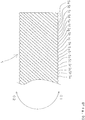
- FIG. 4 is a diagram explaining the multi-stripe hollow body 1 of the embodiment.
- the inner multi-stripe hollow body 3 and the outer multi-stripe hollow body 5 have winding in the same direction (D2 direction in FIG. 4 )
- the single-stripe hollow body 7 has winding in an opposite direction to the inner multi-stripe hollow body 3 and the outer multi-stripe hollow body 5 (D1 direction in FIG. 4 ).
- a twisting angle of the outer multi-stripe hollow body 5 is larger than a twisting angle of the inner multi-stripe hollow body 3, and a twisting angle of the single-stripe hollow body 7 is larger than a twisting angle of the outer multi-stripe hollow body 5.
- FIG. 5 is a section explanatory diagram of the multi-stripe hollow body 1 of the first embodiment, and illustrates that the outer multi-stripe hollow body 5 is of 18 stripes formed of 18 metal element wires of metal wires 5a, 5b, 5c, 5d, 5e, 5f, 5g, 5h, 5j, 5k, 5m, 5n, 5p, 5q, 5r, 5s, 5t, 5u, that the inner multi-stripe hollow body 3 is of six stripes formed of six metal element wires of metal wires 3a, 3b, 3c, 3d, 3e, 3f, and that the single-stripe hollow body 7 is of one stripe formed of one metal element wire of only metal element wire 7a.
- the outer multi-stripe hollow body 5 is of 18 stripes formed of 18 metal element wires of metal wires 5a, 5b, 5c, 5d, 5e, 5f, 5g, 5h, 5j, 5k, 5m, 5n, 5p, 5q, 5r
- multi-stripe hollow body 1 has been described in the embodiment, with the element wire 2 arranged inside the inner multi-stripe hollow body 3 of FIG. 5 , a solid (structure without an inner hollow) multi-stripe body 4 can be formed.
- multi-stripe body is a concept including a “hollow multi-stripe body (multi-stripe hollow body)” and a “solid multi-stripe body”, and is a wider concept than the "multi-stripe hollow body”.
- one element wire 2 is arranged in the center.
- what is arranged in the center is not limited to one element wire, and may be one formed of a plurality of element wires or a stranded wire formed by twisting a plurality of element wires.
- the metal element wires are wound in a counterclockwise direction (A2 direction in FIG. 1 , C2 direction in FIG. 3 ) toward the distal end side.
- the metal element wire is wound in a clockwise direction (B1 direction in FIG. 2 ) toward the distal end side.
- the metal element wires are wound in a counterclockwise direction (C2 direction in FIG. 3 ) toward the distal end side.
- C2 direction in FIG. 3 a proximal end of the outer multi-stripe hollow body 5 is rotated in a clockwise direction (C1 direction in FIG. 3 )
- an outer diameter of the outer multi-stripe hollow body 5 becomes small.
- the metal element wire is wound in a clockwise direction (B1 direction in FIG. 2 ) toward the distal end side.
- the single-stripe hollow body 7 is of a single-stripe with a large twisting angle, and thus an amount by which the outer diameter increases when one end is rotated is small.
- the multi-stripe hollow body 1 illustrated in FIG. 4 will be referred to.
- the proximal end of the multi-stripe hollow body 1 is rotated in a clockwise direction (D1 direction in FIG. 4 )
- the outer diameter of the inner multi-stripe hollow body 3 becomes small
- the outer diameter of the single-stripe hollow body 7 becomes large, so that the space between the inner multi-stripe hollow body 3 and the single-stripe hollow body 7 tends to increase.
- the single-stripe hollow body 7 is of a single-stripe with a large twisting angle, and thus an amount by which the space increases is small.
- the metal element wires are wound in a counterclockwise direction (A2 direction in FIG. 1 ) toward the distal end side.
- A2 direction in FIG. 1 the metal element wires are wound in a counterclockwise direction toward the distal end side.
- the metal element wires are wound in a counterclockwise direction (C2 direction in FIG. 3 ) toward the distal end side.
- C2 direction in FIG. 3 the proximal end of the outer multi-stripe hollow body 5 is rotated in a counterclockwise direction (C2 direction in FIG. 3 )
- an outer diameter of the outer multi-stripe hollow body 5 becomes large.
- the metal element wire is wound in a clockwise direction (B1 direction in FIG. 2 ) toward the distal end side.
- B1 direction in FIG. 2 the proximal end of the single-stripe hollow body 7 is rotated in a counterclockwise direction (B2 direction in FIG. 2 )
- an outer diameter of the single-stripe hollow body 7 becomes small.
- the single-stripe hollow body 7 is of a single-stripe with a large twisting angle, and thus an amount by which the outer diameter reduces when one end is rotated is small.
- the multi-stripe hollow body 1 illustrated in FIG. 4 will be referred to.
- the proximal end of the multi-stripe hollow body 1 is rotated in a counterclockwise direction (D2 direction in FIG. 4 ), the outer diameter of the outer multi-stripe hollow body 5 becomes large, and the outer diameter of the single-stripe hollow body 7 becomes small, so that the space between the outer multi-stripe hollow body 5 and the single-stripe hollow body 7 tends to increase.
- the single-stripe hollow body 7 is of a single-stripe with a large twisting angle, and thus an amount by which the space increases is small.
- the adhesion between the single-stripe hollow body 7 and the inner multi-stripe hollow body 3 is increased, and the space between the single-stripe hollow body 7 and the outer multi-stripe hollow body 5 is reduced as much as possible, or the adhesion between the single-stripe hollow body 7 and the outer multi-stripe hollow body 5 is increased, and the space between the single-stripe hollow body 7 and the inner multi-stripe hollow body 3 is reduced as much as possible, whereby when one end of the multi-stripe hollow body 1 and the multi-stripe body 4 is rotated in both a clockwise direction and a counterclockwise direction, it is possible to improve rotational torque transmissivity to the other end of the multi-stripe hollow body 1.
- the multi-stripe hollow body 1 of the embodiment is a three-stripe hollow body including the inner multi-stripe hollow body 3 and the outer multi-stripe hollow body 5 with winding in a same direction, and the single-stripe hollow body 7 arranged between the inner multi-stripe hollow body 3 and the outer multi-stripe hollow body 5 with winding in an opposite direction from the inner multi-stripe hollow body 3 and the outer multi-stripe hollow body 5.
- the embodiment is not limited to a three-stripe hollow body, and the multi-stripe hollow body may be of four or more-stripe.
- the multi-stripe hollow body includes a plurality of the above-described three-stripe hollow bodies, the same effects as the above are exerted.
- the multi-stripe body 4 of the embodiment is a four-stripe solid body including one element wire 2, the inner multi-stripe hollow body 3 and the outer multi-stripe hollow body 5 with winding in a same direction, and the single-stripe hollow body 7 arranged between the inner multi-stripe hollow body 3 and the outer multi-stripe hollow body 5 with winding in an opposite direction from the inner multi-stripe hollow body 3 and the outer multi-stripe hollow body 5.
- the embodiment is not limited to a four-stripe solid body, and may be of five or more-stripe.
- a three-stripe hollow body including at least a one-stripe single-stripe hollow body, and two multi-stripe hollow bodies that are disposed adjacently to the inner side and the outer side of the single-stripe hollow body with winding in an opposite direction from the one-stripe single-stripe coil.
- the multi-stripe body includes a plurality of the above-described three-stripe hollow bodies, the same effects as the above are exerted.
- FIG. 6 is a schematic side view of a catheter according to the second embodiment.
- a catheter 11 includes the multi-stripe hollow body 1 of the first embodiment, a distal end tip 13 connected to a distal end of the multi-stripe hollow body 1, and a connector 15 connected to a proximal end of the multi-stripe hollow body 1.
- multi-stripe hollow body 1 used in the embodiment, various multi-stripe hollow bodies can be applied, as described in the first embodiment.
- the distal end tip 13 includes a lumen (not illustrated) communicated to a lumen of the multi-stripe hollow body 1.
- the distal end of the distal end tip 13 has a tapered form thinner toward the distal end.
- the material of the distal end tip 13 is metal, resin, or the like, and is not particularly limited. However, it is preferably metal when the material of the multi-stripe hollow body 1 is metal. With this, the distal end tip 13 and the multi-stripe hollow body 1 can be joined firmly by welding.
- the connector 15 also has a lumen communicated to the lumen of the multi-stripe hollow body 1.
- the material of the connector 15 is not particularly limited. However, it is normally formed of resin.
- the catheter 11 of the embodiment includes the multi-stripe hollow body 1.
- the connector 15 when the connector 15 is rotated in a counterclockwise direction (E2 direction in FIG. 6 ), the adhesion between the single-stripe hollow body 7 and the inner multi-stripe hollow body 3 is increased, and the space between the single-stripe hollow body 7 and the outer multi-stripe hollow body 5 is reduced as much as possible, whereby it is possible to improve torque transmissivity to the distal end tip 13 of the catheter 11.
- FIG. 7 is a schematic side view of a catheter according to a third embodiment.
- FIG. 8 is a section view of a distal end of the catheter according to the third embodiment.
- a catheter 21 includes a catheter main body 29, a distal end tip 23 connected to a distal end of the catheter main body 29, and the connector 15 connected to a proximal end of the catheter main body 29.
- the catheter main body 29 includes, as illustrated in FIG. 8 , an inner layer 22 that is a hollow cylindrical body having a lumen 32, a braid 24 covering an outer periphery of the inner layer 22, the multi-stripe hollow body 1 of the first embodiment covering the braid 24, and an outer layer 28 covering the multi-stripe hollow body 1.
- multi-stripe hollow body 1 used in the embodiment, various multi-stripe hollow bodies can be applied, as described in the first embodiment.
- the distal end tip 23 includes a lumen 31 communicated to the lumen 32 of the multi-stripe hollow body 1.
- the distal end of the distal end tip 23 has a tapered form thinner toward the distal end.
- the material of the distal end tip 23 is not particularly limited. However, in the embodiment, a material formed of resin softer than the catheter main body 29 is used.
- the inner layer 22 and the braid 24 extend to the distal end of the distal end tip 23 from the catheter main body 29.
- the multi-stripe hollow body 1 also extends into the distal end tip 23 from the catheter main body 29.
- a marker 26 formed of a radiopaque material is disposed in the distal end tip 23 .
- the connector 15 also has a lumen communicated to the lumen 32 of the multi-stripe hollow body 1.
- the material of the connector 15 is not particularly limited. However, it is normally formed of resin.
- the catheter 21 of the embodiment includes the multi-stripe hollow body 1, and the multi-stripe hollow body 1 enters the inside of the distal end tip 23.
- the connector 15 is rotated in a counterclockwise direction (F2 direction in FIG. 7 )
- the adhesion between the single-stripe hollow body 7 and the inner multi-stripe hollow body 3 is increased, and the space between the single-stripe hollow body 7 and the outer multi-stripe hollow body 5 is reduced as much as possible, whereby it is possible to improve torque transmissivity to the distal end tip 23 of the catheter 21.
- the multi-stripe body, the multi-stripe hollow body, and the catheter according to the embodiment of the invention have been described above.
- the invention is not limited to the above-described embodiments, and can be implemented with various changes within a range not deviated from the scope of the invention.
- the element wire forming the multi-stripe body and the multi-stripe hollow body is an element wire with a round section.
- it may be an element wire with a substantially rectangular section.
- the element wire with a round section is preferable from the viewpoint of preventing a catch in the outside.
Landscapes
- Health & Medical Sciences (AREA)
- Life Sciences & Earth Sciences (AREA)
- Heart & Thoracic Surgery (AREA)
- Hematology (AREA)
- Engineering & Computer Science (AREA)
- Anesthesiology (AREA)
- Biomedical Technology (AREA)
- Pulmonology (AREA)
- Animal Behavior & Ethology (AREA)
- General Health & Medical Sciences (AREA)
- Public Health (AREA)
- Veterinary Medicine (AREA)
- Biophysics (AREA)
- Media Introduction/Drainage Providing Device (AREA)
- Ropes Or Cables (AREA)
- Materials For Medical Uses (AREA)
Abstract
Description
- The present invention relates to a multilayer body including a plurality of concentric layers, a multilayer hollow body with a plurality of hollow bodies arranged concentrically, and a catheter with such a multilayer hollow body.
- Conventionally, there have been variously proposed multilayer bodies including a plurality of concentric layers.
- For example,
Patent Literature 1 describes a plural layered and twisted spiral rope (hereinafter, referred to as a "multilayer body") in which S-twisted layers and Z-twisted layers, which are formed by S-twisting or Z-twisting (twist in an opposite direction of S-twist) a plurality of wires around a core wire 6, are arranged alternately in a plurality of layers (see Paragraph [0009] andFIG. 1(c) , etc.). - However, in the multilayer body described in
Patent Literature 1, the stranded wires formed of a plurality of wires are arranged in a plurality of layers around the core wire. Therefore, a stranding angle of the stranded wire in each layer is small, and when one end of the multilayer body is rotated rightward and leftward, the rotational torque transmissivity to the other end has been insufficient. - Moreover, such a problem has occurred similarly not only in a multilayer body but also in a multilayer hollow body formed by removing a core from a multilayer body, and further in a catheter using a multilayer hollow body.
- Patent Literature 1: Japanese Patent Application Laid-open No.
2000-160488 - The present invention has been made to solve the above-described problem, and aims at providing a multilayer body, a multilayer hollow body, and a catheter with a multilayer hollow body having improved rotational torque transmissivity to the other end when one end is rotated rightward and leftward.
- To achieve such an object, the first aspect of the invention is a multilayer body, including a single-stripe hollow body that is wound by one element wire, an inner multi-stripe hollow body that is disposed adjacently to an inner periphery of the single-stripe hollow body and wound by a plurality of element wires in an opposite direction from the single-stripe hollow body, and an outer multi-stripe hollow body that is disposed adjacently to an outer periphery of the single-stripe hollow body and wound by a plurality of element wires in an opposite direction from the single-stripe hollow body.
- Moreover, the second aspect of the invention is a multilayer hollow body, including a single-stripe hollow body that is wound by one element wire, an inner multi-stripe hollow body that is disposed adjacently to an inner periphery of the single-stripe hollow body and wound by a plurality of element wires in an opposite direction from the single-stripe hollow body, and an outer multi-stripe hollow body that is disposed adjacently to an outer periphery of the single-stripe hollow body and wound by a plurality of element wires in an opposite direction from the single-stripe hollow body.
- Moreover, the third aspect of the invention is a catheter, including the multilayer hollow body of the second aspect, a distal end tip that is connected to a distal end of the multilayer hollow body, and a connector that is connected to a proximal end of the multilayer hollow body.
- Furthermore, the fourth aspect of the invention is a catheter, including an inner layer, the multilayer hollow body of the second aspect that is disposed on an outer periphery of the inner layer, an outer layer that covers the inner layer and the multilayer hollow body, a distal end tip that includes a distal end of the multilayer hollow body inside the distal end tip and is connected to a distal end of the inner layer and a distal end of the outer layer, and a connector that is connected to a proximal end of the inner layer, a proximal end of the outer layer, and a proximal end of the multilayer hollow body.
- The multilayer body according to the first aspect of the invention includes a single-stripe hollow body that is wound by one element wire, an inner multi-stripe hollow body that is disposed adjacently to an inner periphery of the single-stripe hollow body and wound by a plurality of element wires in an opposite direction from the single-stripe hollow body, and an outer multi-stripe hollow body that is disposed adjacently to an outer periphery of the single-stripe hollow body and wound by a plurality of element wires in an opposite direction from the single-stripe hollow body. Thus, when one end of the multilayer body is rotated rightward and leftward, it is possible to improve rotational torque transmissivity to the other end of the multilayer body.
- Moreover, the multilayer hollow body according to the second aspect includes a single-stripe hollow body wound by one element wire, an inner multi-stripe hollow body that is disposed adjacently to an inner periphery of the single-stripe hollow body and wound by a plurality of element wires in an opposite direction from the single-stripe hollow body, and an outer multi-stripe hollow body that is disposed adjacently to an outer periphery of the single-stripe hollow body and wound by a plurality of element wires in an opposite direction from the single-stripe hollow body. Thus, when one end of the multilayer hollow body is rotated rightward and leftward, it is possible to improve rotational torque transmissivity to the other end of the multilayer hollow body.
- Moreover, the catheter according to the third aspect includes the multilayer hollow body of the second aspect, a distal end tip that is connected to a distal end of the multilayer hollow body, and a connector that is connected to a proximal end of the multilayer hollow body. Thus, when one end of the catheter is rotated rightward and leftward, it is possible to improve rotational torque transmissivity to the other end of the catheter.
- Furthermore, the catheter according to the fourth aspect includes an inner layer, the multilayer hollow body of the second aspect that is disposed on an outer periphery of the inner layer, an outer layer that covers the inner layer and the multilayer hollow body, a distal end tip that includes a distal end of the multilayer hollow body inside the distal end tip and is connected to a distal end of the inner layer and a distal end of the outer layer, and a connector that is connected to a proximal end of the inner layer, a proximal end of the outer layer, and a proximal end of the multilayer hollow body. Thus, when one end of the catheter is rotated rightward and leftward, it is possible to further improve rotational torque transmissivity to the other end of the catheter.
-
-
FIG. 1 is a side view of an inner multi-stripe hollow body according to a first embodiment of the invention. -
FIG. 2 is a side view of a single-stripe hollow body according to the first embodiment. -
FIG. 3 is a side view of an outer multi-stripe hollow body according to the first embodiment. -
FIG. 4 is an explanatory diagram of a multi-stripe hollow body according to the first embodiment. -
FIG. 5 is a section explanatory diagram of the multi-stripe hollow body according to the first embodiment. -
FIG. 6 is a schematic side view of a catheter according to a second embodiment. -
FIG. 7 is a schematic side view of a catheter according to a third embodiment. -
FIG. 8 is a distal end section view of the catheter according to the third embodiment. - The following will describe the above-described embodiments of the invention with reference to the enclosed drawings.
-
FIG. 1 is a side view of an inner multi-stripe hollow body according to a first embodiment of the invention.FIG. 2 is a side view of a single-stripe hollow body according to the first embodiment.FIG. 3 is a side view of an outer multi-stripe hollow body according to the first embodiment.FIG. 4 is an explanatory diagram of a multi-stripe hollow body according to the first embodiment.FIG. 5 is a section explanatory diagram of the multi-stripe hollow body according to the first embodiment. - In
FIG. 1 , the inner multi-stripehollow body 3 is a coil body formed in a hollow form by twisting six element wires. - To be more specific, the inner multi-stripe
hollow body 3 is formed in a hollow form by windingmetal element wires - Note that the inner multi-stripe
hollow body 3 in the embodiment is formed by twisting six element wires. However, the embodiment is not limited to one formed by twisting six element wires as long as it is formed by twisting two or more element wires. - Moreover, the material of the element wire forming the inner multi-stripe
hollow body 3 is not limited to a stainless alloy, and may be other kinds of metal, e.g., tungsten, platinum, and gold, or resin. - Note that the
metal element wires hollow body 3 of the embodiment are wound in a counterclockwise direction (A2 direction inFIG. 1 ) toward the left side in the drawing (hereinafter, referred to as a "distal end side"). - In
FIG. 2 , a single-stripehollow body 7 is a coil body formed in a hollow form by twisting one element wire. - To be more specific, the single-stripe
hollow body 7 is formed by winding ametal element wire 7a of one stainless alloy. - Note that the material of the element wire forming the single-stripe
hollow body 7 is not limited to a stainless alloy, and may be other kinds of metal, e.g., tungsten, platinum, and gold, or resin. - Note that the
metal element wire 7a forming the single-stripehollow body 7 of the embodiment is wound in a clockwise direction (B1 direction inFIG. 2 ) toward the left side in the drawing (hereinafter, referred to as a "distal end side"). - In
FIG. 3 , an outer multi-stripehollow body 5 is a coil body formed in a hollow form by twisting 18 element wires, similarly to the inner multi-stripehollow body 3. - To be more specific, the outer multi-stripe
hollow body 5 is formed by windingmetal element wires - Note that the outer multi-stripe
hollow body 5 of the embodiment is formed by twisting 18 element wires. However, the embodiment is not limited to one formed by twisting 18 element wires, and it may be formed by twisting two or more element wires as long as it covers the single-stripehollow body 7. The material of the element wire forming the outer multi-stripehollow body 5 is not limited to a stainless alloy, and may be other kinds of metals, e.g., tungsten, platinum, gold, or resin. - Note that the
metal element wires hollow body 5 in the embodiment are wound in a counterclockwise direction (C2 direction inFIG. 3 ) toward the left side in the drawing (hereinafter, referred to as a "distal end side"). -
FIG. 4 is a diagram explaining the multi-stripehollow body 1 of the embodiment. InFIG. 4 , the inner multi-stripehollow body 3 and the outer multi-stripehollow body 5 have winding in the same direction (D2 direction inFIG. 4 ), and the single-stripehollow body 7 has winding in an opposite direction to the inner multi-stripehollow body 3 and the outer multi-stripe hollow body 5 (D1 direction inFIG. 4 ). - Moreover, in
FIG. 4 , a twisting angle of the outer multi-stripehollow body 5 is larger than a twisting angle of the inner multi-stripehollow body 3, and a twisting angle of the single-stripehollow body 7 is larger than a twisting angle of the outer multi-stripehollow body 5. -
FIG. 5 is a section explanatory diagram of the multi-stripehollow body 1 of the first embodiment, and illustrates that the outer multi-stripehollow body 5 is of 18 stripes formed of 18 metal element wires ofmetal wires hollow body 3 is of six stripes formed of six metal element wires ofmetal wires hollow body 7 is of one stripe formed of one metal element wire of onlymetal element wire 7a. - Note that although the multi-stripe
hollow body 1 has been described in the embodiment, with theelement wire 2 arranged inside the inner multi-stripehollow body 3 ofFIG. 5 , a solid (structure without an inner hollow)multi-stripe body 4 can be formed. - Note that "multi-stripe body" is a concept including a "hollow multi-stripe body (multi-stripe hollow body)" and a "solid multi-stripe body", and is a wider concept than the "multi-stripe hollow body".
- Moreover, in the
multi-stripe body 4 inFIG. 5 , oneelement wire 2 is arranged in the center. However, what is arranged in the center is not limited to one element wire, and may be one formed of a plurality of element wires or a stranded wire formed by twisting a plurality of element wires. - Next, the reason why the rotational torque transmissivity of the multi-stripe
hollow body 1 is improved will be described with reference toFIG. 1 to FIG. 5 . - As described above, in the inner multi-stripe
hollow body 3 and the outer multi-stripehollow body 5, the metal element wires are wound in a counterclockwise direction (A2 direction inFIG. 1 , C2 direction inFIG. 3 ) toward the distal end side. In the single-stripehollow body 7, the metal element wire is wound in a clockwise direction (B1 direction inFIG. 2 ) toward the distal end side. - 1. Case of rotating a proximal end of the hollow
multi-stripe body 1 in a clockwise direction (D1 direction inFIG. 4 ) In the inner multi-stripehollow body 3, the metal element wires are wound in a counterclockwise direction (A2 direction inFIG. 1 ) toward the distal end side. Thus, when the proximal end of the inner multi-stripehollow body 3 is rotated in a clockwise direction (A1 direction inFIG. 1 ), an outer diameter of the inner multi-stripehollow body 3 becomes small. - Also in the outer multi-stripe
hollow body 5, the metal element wires are wound in a counterclockwise direction (C2 direction inFIG. 3 ) toward the distal end side. Thus, when a proximal end of the outer multi-stripehollow body 5 is rotated in a clockwise direction (C1 direction inFIG. 3 ), an outer diameter of the outer multi-stripehollow body 5 becomes small. - By contrast, in the single-stripe
hollow body 7, the metal element wire is wound in a clockwise direction (B1 direction inFIG. 2 ) toward the distal end side. Thus, when a proximal end of the single-stripehollow body 7 is rotated in a clockwise direction (B1 direction inFIG. 2 ), an outer diameter of the single-stripehollow body 7 becomes large. - However, the single-stripe
hollow body 7 is of a single-stripe with a large twisting angle, and thus an amount by which the outer diameter increases when one end is rotated is small. - Here, the multi-stripe
hollow body 1 illustrated inFIG. 4 will be referred to. - In
FIG. 4 , when the proximal end of the multi-stripehollow body 1 including the inner multi-stripehollow body 3, the single-stripehollow body 7, and the outer multi-stripehollow body 5 is rotated in a clockwise direction (D1 direction inFIG. 4 ), the outer diameter of the inner multi-stripehollow body 3 becomes small, the outer diameter of the single-stripehollow body 7 becomes large, and the outer diameter of the outer multi-stripehollow body 5 becomes small. Consequently, the adhesion between the single-stripehollow body 7 and the outer multi-stripehollow body 5 is increased. - Meanwhile, when the proximal end of the multi-stripe
hollow body 1 is rotated in a clockwise direction (D1 direction inFIG. 4 ), the outer diameter of the inner multi-stripehollow body 3 becomes small, and the outer diameter of the single-stripehollow body 7 becomes large, so that the space between the inner multi-stripehollow body 3 and the single-stripehollow body 7 tends to increase. However, the single-stripehollow body 7 is of a single-stripe with a large twisting angle, and thus an amount by which the space increases is small. - Therefore, when the proximal end of the multi-stripe
hollow body 1 is rotated in a clockwise direction (D1 direction inFIG. 4 ), it is possible to improve rotational torque transmissivity to the distal end of the multi-stripehollow body 1. - 2. Case of rotating a proximal end of the hollow
multi-stripe body 1 in a counterclockwise direction - In the inner multi-stripe
hollow body 3, the metal element wires are wound in a counterclockwise direction (A2 direction inFIG. 1 ) toward the distal end side. Thus, when the proximal end of the inner multi-stripehollow body 3 is rotated in a counterclockwise direction (A2 direction inFIG. 1 ), an outer diameter of the inner multi-stripehollow body 3 becomes large. - Also in the outer multi-stripe
hollow body 5, the metal element wires are wound in a counterclockwise direction (C2 direction inFIG. 3 ) toward the distal end side. Thus, when the proximal end of the outer multi-stripehollow body 5 is rotated in a counterclockwise direction (C2 direction inFIG. 3 ), an outer diameter of the outer multi-stripehollow body 5 becomes large. - Meanwhile, in the single-stripe
hollow body 7, the metal element wire is wound in a clockwise direction (B1 direction inFIG. 2 ) toward the distal end side. Thus, when the proximal end of the single-stripehollow body 7 is rotated in a counterclockwise direction (B2 direction inFIG. 2 ), an outer diameter of the single-stripehollow body 7 becomes small. - However, the single-stripe
hollow body 7 is of a single-stripe with a large twisting angle, and thus an amount by which the outer diameter reduces when one end is rotated is small. - Here, the multi-stripe
hollow body 1 illustrated inFIG. 4 will be referred to. - In
FIG. 4 , when the proximal end of the multi-stripehollow body 1 including the inner multi-stripehollow body 3, the single-stripehollow body 7, and the outer multi-stripehollow body 5 is rotated in a counterclockwise direction (D2 direction inFIG. 4 ), the outer diameter of the inner multi-stripehollow body 3 becomes large, the outer diameter of the single-stripehollow body 7 becomes small, and the outer diameter of the outer multi-stripehollow body 5 becomes large. Consequently, the adhesion between the single-stripehollow body 7 and the inner multi-stripehollow body 3 is increased. - Meanwhile, when the proximal end of the multi-stripe
hollow body 1 is rotated in a counterclockwise direction (D2 direction inFIG. 4 ), the outer diameter of the outer multi-stripehollow body 5 becomes large, and the outer diameter of the single-stripehollow body 7 becomes small, so that the space between the outer multi-stripehollow body 5 and the single-stripehollow body 7 tends to increase. However, the single-stripehollow body 7 is of a single-stripe with a large twisting angle, and thus an amount by which the space increases is small. - Therefore, when the proximal end of the multi-stripe
hollow body 1 is rotated in a counterclockwise direction (D2 direction inFIG. 4 ), it is possible to improve rotational torque transmissivity to the distal end of the multi-stripehollow body 1. - Note that a reason why the rotational torque transmissivity of the
multi-stripe body 4 is improved is the same as the above-described reason as to why the rotational torque transmissivity of the multi-stripehollow body 1 is improved, and thus the explanation thereof is omitted. - With the multi-stripe
hollow body 1 and themulti-stripe body 4 of the embodiment, the adhesion between the single-stripehollow body 7 and the inner multi-stripehollow body 3 is increased, and the space between the single-stripehollow body 7 and the outer multi-stripehollow body 5 is reduced as much as possible, or the adhesion between the single-stripehollow body 7 and the outer multi-stripehollow body 5 is increased, and the space between the single-stripehollow body 7 and the inner multi-stripehollow body 3 is reduced as much as possible, whereby when one end of the multi-stripehollow body 1 and themulti-stripe body 4 is rotated in both a clockwise direction and a counterclockwise direction, it is possible to improve rotational torque transmissivity to the other end of the multi-stripehollow body 1. - Note that the multi-stripe
hollow body 1 of the embodiment is a three-stripe hollow body including the inner multi-stripehollow body 3 and the outer multi-stripehollow body 5 with winding in a same direction, and the single-stripehollow body 7 arranged between the inner multi-stripehollow body 3 and the outer multi-stripehollow body 5 with winding in an opposite direction from the inner multi-stripehollow body 3 and the outer multi-stripehollow body 5. However, the embodiment is not limited to a three-stripe hollow body, and the multi-stripe hollow body may be of four or more-stripe. - However, it is necessary to provide at least a one-stripe single-stripe hollow body, and two multi-stripe hollow bodies that are disposed adjacently to the inner side and the outer side of the single-stripe hollow body with winding in an opposite direction from the one-stripe single-stripe coil.
- Moreover, even when the multi-stripe hollow body includes a plurality of the above-described three-stripe hollow bodies, the same effects as the above are exerted.
- Moreover, the
multi-stripe body 4 of the embodiment is a four-stripe solid body including oneelement wire 2, the inner multi-stripehollow body 3 and the outer multi-stripehollow body 5 with winding in a same direction, and the single-stripehollow body 7 arranged between the inner multi-stripehollow body 3 and the outer multi-stripehollow body 5 with winding in an opposite direction from the inner multi-stripehollow body 3 and the outer multi-stripehollow body 5. However, the embodiment is not limited to a four-stripe solid body, and may be of five or more-stripe. - However, it is necessary to provide a three-stripe hollow body including at least a one-stripe single-stripe hollow body, and two multi-stripe hollow bodies that are disposed adjacently to the inner side and the outer side of the single-stripe hollow body with winding in an opposite direction from the one-stripe single-stripe coil.
- Moreover, even when the multi-stripe body includes a plurality of the above-described three-stripe hollow bodies, the same effects as the above are exerted.
-
FIG. 6 is a schematic side view of a catheter according to the second embodiment. - In
FIG. 6 , acatheter 11 includes the multi-stripehollow body 1 of the first embodiment, adistal end tip 13 connected to a distal end of the multi-stripehollow body 1, and aconnector 15 connected to a proximal end of the multi-stripehollow body 1. - Note that regarding the multi-stripe
hollow body 1 used in the embodiment, various multi-stripe hollow bodies can be applied, as described in the first embodiment. - The
distal end tip 13 includes a lumen (not illustrated) communicated to a lumen of the multi-stripehollow body 1. The distal end of thedistal end tip 13 has a tapered form thinner toward the distal end. - The material of the
distal end tip 13 is metal, resin, or the like, and is not particularly limited. However, it is preferably metal when the material of the multi-stripehollow body 1 is metal. With this, thedistal end tip 13 and the multi-stripehollow body 1 can be joined firmly by welding. - Moreover, the
connector 15 also has a lumen communicated to the lumen of the multi-stripehollow body 1. The material of theconnector 15 is not particularly limited. However, it is normally formed of resin. - The
catheter 11 of the embodiment includes the multi-stripehollow body 1. Thus, when theconnector 15 is rotated in a counterclockwise direction (E2 direction inFIG. 6 ), the adhesion between the single-stripehollow body 7 and the inner multi-stripehollow body 3 is increased, and the space between the single-stripehollow body 7 and the outer multi-stripehollow body 5 is reduced as much as possible, whereby it is possible to improve torque transmissivity to thedistal end tip 13 of thecatheter 11. - Moreover, when the
connector 15 is rotated in a clockwise direction (E1 direction inFIG. 6 ), the adhesion between the single-stripehollow body 7 and the outer multi-stripehollow body 5 is increased, and the space between the single-stripehollow body 7 and the inner multi-stripehollow body 3 is reduced as much as possible, whereby it is possible to improve torque transmissivity to thedistal end tip 13 of thecatheter 11. -
FIG. 7 is a schematic side view of a catheter according to a third embodiment.FIG. 8 is a section view of a distal end of the catheter according to the third embodiment. - In
FIG. 7 , acatheter 21 includes a cathetermain body 29, adistal end tip 23 connected to a distal end of the cathetermain body 29, and theconnector 15 connected to a proximal end of the cathetermain body 29. - The catheter
main body 29 includes, as illustrated inFIG. 8 , aninner layer 22 that is a hollow cylindrical body having alumen 32, abraid 24 covering an outer periphery of theinner layer 22, the multi-stripehollow body 1 of the first embodiment covering thebraid 24, and anouter layer 28 covering the multi-stripehollow body 1. - Note that regarding the multi-stripe
hollow body 1 used in the embodiment, various multi-stripe hollow bodies can be applied, as described in the first embodiment. - The
distal end tip 23 includes alumen 31 communicated to thelumen 32 of the multi-stripehollow body 1. The distal end of thedistal end tip 23 has a tapered form thinner toward the distal end. - The material of the
distal end tip 23 is not particularly limited. However, in the embodiment, a material formed of resin softer than the cathetermain body 29 is used. - Note that the
inner layer 22 and thebraid 24 extend to the distal end of thedistal end tip 23 from the cathetermain body 29. Moreover, the multi-stripehollow body 1 also extends into thedistal end tip 23 from the cathetermain body 29. - Moreover, in the
distal end tip 23, amarker 26 formed of a radiopaque material is disposed. - Furthermore, the
connector 15 also has a lumen communicated to thelumen 32 of the multi-stripehollow body 1. The material of theconnector 15 is not particularly limited. However, it is normally formed of resin. - The
catheter 21 of the embodiment includes the multi-stripehollow body 1, and the multi-stripehollow body 1 enters the inside of thedistal end tip 23. Thus, when theconnector 15 is rotated in a counterclockwise direction (F2 direction inFIG. 7 ), the adhesion between the single-stripehollow body 7 and the inner multi-stripehollow body 3 is increased, and the space between the single-stripehollow body 7 and the outer multi-stripehollow body 5 is reduced as much as possible, whereby it is possible to improve torque transmissivity to thedistal end tip 23 of thecatheter 21. - Moreover, when the
connector 15 is rotated in a clockwise direction (F1 direction inFIG. 7 ), the adhesion between the single-stripehollow body 7 and the outer multi-stripehollow body 5 is increased, and the space between the single-stripehollow body 7 and the inner multi-stripehollow body 3 is reduced as much as possible, whereby it is possible to improve torque transmissivity to thedistal end tip 23 of thecatheter 21. - The multi-stripe body, the multi-stripe hollow body, and the catheter according to the embodiment of the invention have been described above. However, the invention is not limited to the above-described embodiments, and can be implemented with various changes within a range not deviated from the scope of the invention.
- For example, in the above-described embodiments, the element wire forming the multi-stripe body and the multi-stripe hollow body is an element wire with a round section. However, it may be an element wire with a substantially rectangular section. However, when the multi-stripe body itself or the multi-stripe hollow body itself appears on an outer surface, the element wire with a round section is preferable from the viewpoint of preventing a catch in the outside.
-
- 1
- multi-stripe hollow body
- 2
- element wire
- 3
- inner multi-stripe hollow body
- 4
- multi-stripe body
- 5
- outer multi-stripe hollow body
- 7
- single-stripe hollow body
- 11, 21
- catheter
- 13, 23
- distal end tip
- 15
- connector
- 22
- inner layer
- 24
- braid
- 26
- marker
- 28
- outer layer
- 29
- catheter main body
- 31, 32
- lumen
Claims (4)
- A multilayer body, comprising:a single-stripe hollow body that is wound by one element wire;an inner multi-stripe hollow body that is disposed adjacently to an inner periphery of the single-stripe hollow body and wound by a plurality of element wires in an opposite direction from the single-stripe hollow body; andan outer multi-stripe hollow body that is disposed adjacently to an outer periphery of the single-stripe hollow body and wound by a plurality of element wires in an opposite direction from the single-stripe hollow body.
- A multilayer hollow body, comprising:a single-stripe hollow body that is wound by one element wire;an inner multi-stripe hollow body that is disposed adjacently to an inner periphery of the single-stripe hollow body and wound by a plurality of element wires in an opposite direction from the single-stripe hollow body; andan outer multi-stripe hollow body that is disposed adjacently to an outer periphery of the single-stripe hollow body and wound by a plurality of element wires in an opposite direction from the single-stripe hollow body.
- A catheter, comprising:the multilayer hollow body according to claim 2;a distal end tip that is connected to a distal end of the multilayer hollow body; anda connector that is connected to a proximal end of the multilayer hollow body.
- A catheter, comprising:an inner layer;the multilayer hollow body according to claim 2 that is disposed on an outer periphery of the inner layer;an outer layer that covers the inner layer and the multilayer hollow body;a distal end tip that includes a distal end of the multilayer hollow body inside the distal end tip and is connected to a distal end of the inner layer and a distal end of the outer layer; anda connector that is connected to a proximal end of the inner layer, a proximal end of the outer layer, and a proximal end of the multilayer hollow body.
Applications Claiming Priority (1)
| Application Number | Priority Date | Filing Date | Title |
|---|---|---|---|
| PCT/JP2016/080345 WO2018070008A1 (en) | 2016-10-13 | 2016-10-13 | Multi-layer body, multi-layer hollow body, and catheter provided with multi-layer hollow body |
Publications (3)
| Publication Number | Publication Date |
|---|---|
| EP3527718A1 true EP3527718A1 (en) | 2019-08-21 |
| EP3527718A4 EP3527718A4 (en) | 2020-08-26 |
| EP3527718B1 EP3527718B1 (en) | 2023-10-04 |
Family
ID=61902474
Family Applications (1)
| Application Number | Title | Priority Date | Filing Date |
|---|---|---|---|
| EP16856451.6A Active EP3527718B1 (en) | 2016-10-13 | 2016-10-13 | Multi-layer body, multi-layer hollow body, and catheter provided with multi-layer hollow body |
Country Status (6)
| Country | Link |
|---|---|
| US (1) | US10912921B2 (en) |
| EP (1) | EP3527718B1 (en) |
| JP (1) | JP6329695B1 (en) |
| KR (1) | KR20180065965A (en) |
| CN (1) | CN109312534A (en) |
| WO (1) | WO2018070008A1 (en) |
Families Citing this family (4)
| Publication number | Priority date | Publication date | Assignee | Title |
|---|---|---|---|---|
| KR20200108038A (en) * | 2018-01-26 | 2020-09-16 | 아사히 인텍크 가부시키가이샤 | Catheter |
| US10512753B1 (en) | 2018-12-07 | 2019-12-24 | John Nguyen | Composite catheter shafts and methods and apparatus for making the same |
| US12296181B2 (en) * | 2019-11-08 | 2025-05-13 | Pacesetter, Inc. | Biostimulator transport system having swaged torque shaft |
| CN112826537A (en) * | 2020-12-31 | 2021-05-25 | 上海爱声生物医疗科技有限公司 | An endoscopic ultrasound microprobe |
Family Cites Families (26)
| Publication number | Priority date | Publication date | Assignee | Title |
|---|---|---|---|---|
| US1905197A (en) * | 1929-02-06 | 1933-04-25 | Ac Spark Plug Co | Flexible cable |
| US5154705A (en) * | 1987-09-30 | 1992-10-13 | Lake Region Manufacturing Co., Inc. | Hollow lumen cable apparatus |
| US6210395B1 (en) * | 1987-09-30 | 2001-04-03 | Lake Region Mfg., Inc. | Hollow lumen cable apparatus |
| US5165421A (en) * | 1987-09-30 | 1992-11-24 | Lake Region Manufacturing Co., Inc. | Hollow lumen cable apparatus |
| US5052404A (en) * | 1989-03-02 | 1991-10-01 | The Microspring Company, Inc. | Torque transmitter |
| US5306252A (en) * | 1991-07-18 | 1994-04-26 | Kabushiki Kaisha Kobe Seiko Sho | Catheter guide wire and catheter |
| JPH0723956A (en) * | 1993-07-09 | 1995-01-27 | Matsushita Electric Ind Co Ltd | Ultrasonic diagnostic device and propagation medium injection method |
| JPH07178176A (en) * | 1993-12-24 | 1995-07-18 | Terumo Corp | Catheter |
| JP3109415B2 (en) * | 1995-08-07 | 2000-11-13 | トヨタ自動車株式会社 | Flexible shaft structure |
| CN2302280Y (en) * | 1997-10-17 | 1998-12-30 | 杨树仁 | Hollow soft roller wire core |
| EP1042618A1 (en) * | 1997-12-31 | 2000-10-11 | Jack W. Romano | Method and apparatus for transferring drilling energy to a cutting member |
| JP3650530B2 (en) * | 1998-08-18 | 2005-05-18 | 三菱電線工業株式会社 | Torque transmission tube and endoscope |
| JP2000160488A (en) | 1998-11-27 | 2000-06-13 | Tokyo Seiko Co Ltd | Manufacturing method of non-rotating spiral rope and non-rotating spiral rope |
| JP2002195240A (en) * | 2000-12-27 | 2002-07-10 | Japan Science & Technology Corp | Multi-turn flexible shaft coupling and surgical instrument using the same |
| US6881194B2 (en) * | 2001-03-21 | 2005-04-19 | Asahi Intec Co., Ltd. | Wire-stranded medical hollow tube, and a medical guide wire |
| US20080097401A1 (en) * | 2006-09-22 | 2008-04-24 | Trapp Benjamin M | Cerebral vasculature device |
| US8764727B2 (en) * | 2009-03-06 | 2014-07-01 | Cook Medical Technologies Llc | Reinforced rapid exchange catheter |
| JP2011006803A (en) * | 2009-06-24 | 2011-01-13 | Hi-Lex Corporation | Inner cable for transmitting rotating torque, and control cable and door-opening and closing mechanism, using the same |
| JP5436266B2 (en) | 2010-02-26 | 2014-03-05 | 朝日インテック株式会社 | Medical coil structure, manufacturing method thereof, medical endoscope formed with medical coil structure, medical treatment instrument, ultrasonic diagnostic medical catheter, and optical interference diagnostic medical catheter |
| CN102913534A (en) * | 2011-08-01 | 2013-02-06 | 舒能(苏州)工业技术有限公司 | Hollow flexible shaft of flat steel wires |
| JP2013085698A (en) | 2011-10-18 | 2013-05-13 | Hi-Lex Corporation | Catheter for stent placement |
| JP6149431B2 (en) * | 2013-03-08 | 2017-06-21 | 住友ベークライト株式会社 | MEDICAL DEVICE, CATHETER AND METHOD FOR PRODUCING MEDICAL DEVICE |
| JP2015051085A (en) * | 2013-09-06 | 2015-03-19 | 朝日インテック株式会社 | Coil body and medical appliance using the same |
| JP2016013269A (en) * | 2014-07-02 | 2016-01-28 | 朝日インテック株式会社 | Guide wire |
| US9782561B2 (en) * | 2014-10-09 | 2017-10-10 | Vacular Solutions, Inc. | Catheter tip |
| EP3072549A1 (en) * | 2015-03-23 | 2016-09-28 | Asahi Intecc Co., Ltd. | Catheter |
-
2016
- 2016-10-13 WO PCT/JP2016/080345 patent/WO2018070008A1/en not_active Ceased
- 2016-10-13 EP EP16856451.6A patent/EP3527718B1/en active Active
- 2016-10-13 JP JP2017508703A patent/JP6329695B1/en active Active
- 2016-10-13 KR KR1020177011396A patent/KR20180065965A/en not_active Ceased
- 2016-10-13 CN CN201680003516.9A patent/CN109312534A/en active Pending
-
2017
- 2017-07-17 US US15/651,491 patent/US10912921B2/en active Active
Also Published As
| Publication number | Publication date |
|---|---|
| JP6329695B1 (en) | 2018-05-23 |
| CN109312534A (en) | 2019-02-05 |
| EP3527718A4 (en) | 2020-08-26 |
| JPWO2018070008A1 (en) | 2018-10-11 |
| EP3527718B1 (en) | 2023-10-04 |
| US10912921B2 (en) | 2021-02-09 |
| WO2018070008A1 (en) | 2018-04-19 |
| KR20180065965A (en) | 2018-06-18 |
| US20180104440A1 (en) | 2018-04-19 |
Similar Documents
| Publication | Publication Date | Title |
|---|---|---|
| EP3527718B1 (en) | Multi-layer body, multi-layer hollow body, and catheter provided with multi-layer hollow body | |
| JP7693777B2 (en) | Aluminum electric wire and manufacturing method thereof | |
| CN105983168B (en) | Catheter tube | |
| JP6936104B2 (en) | Composite stranded conductor and insulated wire equipped with it | |
| KR20140074911A (en) | Connection method between braided shield layer of shield wire and drain wire, and connection structure of the same | |
| JP2012036927A (en) | Rubber hose | |
| US9845572B2 (en) | Core-sheath rope | |
| JP6634396B2 (en) | Aluminum composite stranded conductor, aluminum composite stranded electric wire and wire harness | |
| JP2022111348A (en) | composite cable | |
| US20170328000A1 (en) | Wire rope | |
| US20100043381A1 (en) | Multi-strand steel wire rope | |
| CN111199811A (en) | Composite stranded conductors and flex resistant wires | |
| JP2016179170A (en) | catheter | |
| CN114188076B (en) | cable | |
| US20140318100A1 (en) | Twisted cable | |
| US20210378573A1 (en) | Catheter | |
| US20220170204A1 (en) | Wire rope | |
| US3446248A (en) | Reinforced hose | |
| JP6463453B1 (en) | Stranded conductor | |
| JP6263053B2 (en) | Cable strands and cables | |
| JP2019067647A (en) | power line | |
| JP7524692B2 (en) | Composite Cable | |
| JP7693567B2 (en) | Coil body | |
| JP2024147204A5 (en) | ||
| WO2022190583A1 (en) | Electrode catheter |
Legal Events
| Date | Code | Title | Description |
|---|---|---|---|
| STAA | Information on the status of an ep patent application or granted ep patent |
Free format text: STATUS: UNKNOWN |
|
| STAA | Information on the status of an ep patent application or granted ep patent |
Free format text: STATUS: THE INTERNATIONAL PUBLICATION HAS BEEN MADE |
|
| PUAI | Public reference made under article 153(3) epc to a published international application that has entered the european phase |
Free format text: ORIGINAL CODE: 0009012 |
|
| STAA | Information on the status of an ep patent application or granted ep patent |
Free format text: STATUS: REQUEST FOR EXAMINATION WAS MADE |
|
| 17P | Request for examination filed |
Effective date: 20170424 |
|
| AK | Designated contracting states |
Kind code of ref document: A1 Designated state(s): AL AT BE BG CH CY CZ DE DK EE ES FI FR GB GR HR HU IE IS IT LI LT LU LV MC MK MT NL NO PL PT RO RS SE SI SK SM TR |
|
| AX | Request for extension of the european patent |
Extension state: BA ME |
|
| DAV | Request for validation of the european patent (deleted) | ||
| DAX | Request for extension of the european patent (deleted) | ||
| R17P | Request for examination filed (corrected) |
Effective date: 20170424 |
|
| A4 | Supplementary search report drawn up and despatched |
Effective date: 20200727 |
|
| RIC1 | Information provided on ipc code assigned before grant |
Ipc: A61M 25/00 20060101ALI20200721BHEP Ipc: D07B 1/00 20060101AFI20200721BHEP Ipc: F16C 1/02 20060101ALI20200721BHEP |
|
| GRAP | Despatch of communication of intention to grant a patent |
Free format text: ORIGINAL CODE: EPIDOSNIGR1 |
|
| STAA | Information on the status of an ep patent application or granted ep patent |
Free format text: STATUS: GRANT OF PATENT IS INTENDED |
|
| INTG | Intention to grant announced |
Effective date: 20230421 |
|
| GRAS | Grant fee paid |
Free format text: ORIGINAL CODE: EPIDOSNIGR3 |
|
| GRAA | (expected) grant |
Free format text: ORIGINAL CODE: 0009210 |
|
| STAA | Information on the status of an ep patent application or granted ep patent |
Free format text: STATUS: THE PATENT HAS BEEN GRANTED |
|
| AK | Designated contracting states |
Kind code of ref document: B1 Designated state(s): AL AT BE BG CH CY CZ DE DK EE ES FI FR GB GR HR HU IE IS IT LI LT LU LV MC MK MT NL NO PL PT RO RS SE SI SK SM TR |
|
| RAP3 | Party data changed (applicant data changed or rights of an application transferred) |
Owner name: ASAHI INTECC CO., LTD. |
|
| REG | Reference to a national code |
Ref country code: GB Ref legal event code: FG4D |
|
| RIN1 | Information on inventor provided before grant (corrected) |
Inventor name: HANAOKA ATSUHIRO |
|
| REG | Reference to a national code |
Ref country code: CH Ref legal event code: EP |
|
| REG | Reference to a national code |
Ref country code: DE Ref legal event code: R096 Ref document number: 602016083265 Country of ref document: DE |
|
| REG | Reference to a national code |
Ref country code: IE Ref legal event code: FG4D |
|
| REG | Reference to a national code |
Ref country code: LT Ref legal event code: MG9D |
|
| REG | Reference to a national code |
Ref country code: NL Ref legal event code: MP Effective date: 20231004 |
|
| REG | Reference to a national code |
Ref country code: AT Ref legal event code: MK05 Ref document number: 1617879 Country of ref document: AT Kind code of ref document: T Effective date: 20231004 |
|
| PG25 | Lapsed in a contracting state [announced via postgrant information from national office to epo] |
Ref country code: NL Free format text: LAPSE BECAUSE OF FAILURE TO SUBMIT A TRANSLATION OF THE DESCRIPTION OR TO PAY THE FEE WITHIN THE PRESCRIBED TIME-LIMIT Effective date: 20231004 |
|
| PG25 | Lapsed in a contracting state [announced via postgrant information from national office to epo] |
Ref country code: GR Free format text: LAPSE BECAUSE OF FAILURE TO SUBMIT A TRANSLATION OF THE DESCRIPTION OR TO PAY THE FEE WITHIN THE PRESCRIBED TIME-LIMIT Effective date: 20240105 |
|
| PG25 | Lapsed in a contracting state [announced via postgrant information from national office to epo] |
Ref country code: IS Free format text: LAPSE BECAUSE OF FAILURE TO SUBMIT A TRANSLATION OF THE DESCRIPTION OR TO PAY THE FEE WITHIN THE PRESCRIBED TIME-LIMIT Effective date: 20240204 |
|
| PG25 | Lapsed in a contracting state [announced via postgrant information from national office to epo] |
Ref country code: LT Free format text: LAPSE BECAUSE OF FAILURE TO SUBMIT A TRANSLATION OF THE DESCRIPTION OR TO PAY THE FEE WITHIN THE PRESCRIBED TIME-LIMIT Effective date: 20231004 |
|
| PG25 | Lapsed in a contracting state [announced via postgrant information from national office to epo] |
Ref country code: AT Free format text: LAPSE BECAUSE OF FAILURE TO SUBMIT A TRANSLATION OF THE DESCRIPTION OR TO PAY THE FEE WITHIN THE PRESCRIBED TIME-LIMIT Effective date: 20231004 |
|
| PG25 | Lapsed in a contracting state [announced via postgrant information from national office to epo] |
Ref country code: ES Free format text: LAPSE BECAUSE OF FAILURE TO SUBMIT A TRANSLATION OF THE DESCRIPTION OR TO PAY THE FEE WITHIN THE PRESCRIBED TIME-LIMIT Effective date: 20231004 |
|
| PG25 | Lapsed in a contracting state [announced via postgrant information from national office to epo] |
Ref country code: LT Free format text: LAPSE BECAUSE OF FAILURE TO SUBMIT A TRANSLATION OF THE DESCRIPTION OR TO PAY THE FEE WITHIN THE PRESCRIBED TIME-LIMIT Effective date: 20231004 Ref country code: IS Free format text: LAPSE BECAUSE OF FAILURE TO SUBMIT A TRANSLATION OF THE DESCRIPTION OR TO PAY THE FEE WITHIN THE PRESCRIBED TIME-LIMIT Effective date: 20240204 Ref country code: GR Free format text: LAPSE BECAUSE OF FAILURE TO SUBMIT A TRANSLATION OF THE DESCRIPTION OR TO PAY THE FEE WITHIN THE PRESCRIBED TIME-LIMIT Effective date: 20240105 Ref country code: ES Free format text: LAPSE BECAUSE OF FAILURE TO SUBMIT A TRANSLATION OF THE DESCRIPTION OR TO PAY THE FEE WITHIN THE PRESCRIBED TIME-LIMIT Effective date: 20231004 Ref country code: BG Free format text: LAPSE BECAUSE OF FAILURE TO SUBMIT A TRANSLATION OF THE DESCRIPTION OR TO PAY THE FEE WITHIN THE PRESCRIBED TIME-LIMIT Effective date: 20240104 Ref country code: AT Free format text: LAPSE BECAUSE OF FAILURE TO SUBMIT A TRANSLATION OF THE DESCRIPTION OR TO PAY THE FEE WITHIN THE PRESCRIBED TIME-LIMIT Effective date: 20231004 Ref country code: PT Free format text: LAPSE BECAUSE OF FAILURE TO SUBMIT A TRANSLATION OF THE DESCRIPTION OR TO PAY THE FEE WITHIN THE PRESCRIBED TIME-LIMIT Effective date: 20240205 |
|
| PG25 | Lapsed in a contracting state [announced via postgrant information from national office to epo] |
Ref country code: SE Free format text: LAPSE BECAUSE OF FAILURE TO SUBMIT A TRANSLATION OF THE DESCRIPTION OR TO PAY THE FEE WITHIN THE PRESCRIBED TIME-LIMIT Effective date: 20231004 Ref country code: RS Free format text: LAPSE BECAUSE OF FAILURE TO SUBMIT A TRANSLATION OF THE DESCRIPTION OR TO PAY THE FEE WITHIN THE PRESCRIBED TIME-LIMIT Effective date: 20231004 Ref country code: PL Free format text: LAPSE BECAUSE OF FAILURE TO SUBMIT A TRANSLATION OF THE DESCRIPTION OR TO PAY THE FEE WITHIN THE PRESCRIBED TIME-LIMIT Effective date: 20231004 Ref country code: NO Free format text: LAPSE BECAUSE OF FAILURE TO SUBMIT A TRANSLATION OF THE DESCRIPTION OR TO PAY THE FEE WITHIN THE PRESCRIBED TIME-LIMIT Effective date: 20240104 Ref country code: LV Free format text: LAPSE BECAUSE OF FAILURE TO SUBMIT A TRANSLATION OF THE DESCRIPTION OR TO PAY THE FEE WITHIN THE PRESCRIBED TIME-LIMIT Effective date: 20231004 Ref country code: HR Free format text: LAPSE BECAUSE OF FAILURE TO SUBMIT A TRANSLATION OF THE DESCRIPTION OR TO PAY THE FEE WITHIN THE PRESCRIBED TIME-LIMIT Effective date: 20231004 |
|
| REG | Reference to a national code |
Ref country code: CH Ref legal event code: PL |
|
| REG | Reference to a national code |
Ref country code: BE Ref legal event code: MM Effective date: 20231031 |
|
| PG25 | Lapsed in a contracting state [announced via postgrant information from national office to epo] |
Ref country code: LU Free format text: LAPSE BECAUSE OF NON-PAYMENT OF DUE FEES Effective date: 20231013 |
|
| PG25 | Lapsed in a contracting state [announced via postgrant information from national office to epo] |
Ref country code: LU Free format text: LAPSE BECAUSE OF NON-PAYMENT OF DUE FEES Effective date: 20231013 |
|
| REG | Reference to a national code |
Ref country code: DE Ref legal event code: R097 Ref document number: 602016083265 Country of ref document: DE |
|
| PG25 | Lapsed in a contracting state [announced via postgrant information from national office to epo] |
Ref country code: DK Free format text: LAPSE BECAUSE OF FAILURE TO SUBMIT A TRANSLATION OF THE DESCRIPTION OR TO PAY THE FEE WITHIN THE PRESCRIBED TIME-LIMIT Effective date: 20231004 |
|
| PG25 | Lapsed in a contracting state [announced via postgrant information from national office to epo] |
Ref country code: CH Free format text: LAPSE BECAUSE OF NON-PAYMENT OF DUE FEES Effective date: 20231031 |
|
| PG25 | Lapsed in a contracting state [announced via postgrant information from national office to epo] |
Ref country code: CZ Free format text: LAPSE BECAUSE OF FAILURE TO SUBMIT A TRANSLATION OF THE DESCRIPTION OR TO PAY THE FEE WITHIN THE PRESCRIBED TIME-LIMIT Effective date: 20231004 |
|
| PG25 | Lapsed in a contracting state [announced via postgrant information from national office to epo] |
Ref country code: SK Free format text: LAPSE BECAUSE OF FAILURE TO SUBMIT A TRANSLATION OF THE DESCRIPTION OR TO PAY THE FEE WITHIN THE PRESCRIBED TIME-LIMIT Effective date: 20231004 |
|
| PG25 | Lapsed in a contracting state [announced via postgrant information from national office to epo] |
Ref country code: SM Free format text: LAPSE BECAUSE OF FAILURE TO SUBMIT A TRANSLATION OF THE DESCRIPTION OR TO PAY THE FEE WITHIN THE PRESCRIBED TIME-LIMIT Effective date: 20231004 Ref country code: SK Free format text: LAPSE BECAUSE OF FAILURE TO SUBMIT A TRANSLATION OF THE DESCRIPTION OR TO PAY THE FEE WITHIN THE PRESCRIBED TIME-LIMIT Effective date: 20231004 Ref country code: RO Free format text: LAPSE BECAUSE OF FAILURE TO SUBMIT A TRANSLATION OF THE DESCRIPTION OR TO PAY THE FEE WITHIN THE PRESCRIBED TIME-LIMIT Effective date: 20231004 Ref country code: IT Free format text: LAPSE BECAUSE OF FAILURE TO SUBMIT A TRANSLATION OF THE DESCRIPTION OR TO PAY THE FEE WITHIN THE PRESCRIBED TIME-LIMIT Effective date: 20231004 Ref country code: EE Free format text: LAPSE BECAUSE OF FAILURE TO SUBMIT A TRANSLATION OF THE DESCRIPTION OR TO PAY THE FEE WITHIN THE PRESCRIBED TIME-LIMIT Effective date: 20231004 Ref country code: DK Free format text: LAPSE BECAUSE OF FAILURE TO SUBMIT A TRANSLATION OF THE DESCRIPTION OR TO PAY THE FEE WITHIN THE PRESCRIBED TIME-LIMIT Effective date: 20231004 Ref country code: CZ Free format text: LAPSE BECAUSE OF FAILURE TO SUBMIT A TRANSLATION OF THE DESCRIPTION OR TO PAY THE FEE WITHIN THE PRESCRIBED TIME-LIMIT Effective date: 20231004 Ref country code: CH Free format text: LAPSE BECAUSE OF NON-PAYMENT OF DUE FEES Effective date: 20231031 |
|
| PLBE | No opposition filed within time limit |
Free format text: ORIGINAL CODE: 0009261 |
|
| STAA | Information on the status of an ep patent application or granted ep patent |
Free format text: STATUS: NO OPPOSITION FILED WITHIN TIME LIMIT |
|
| PG25 | Lapsed in a contracting state [announced via postgrant information from national office to epo] |
Ref country code: MC Free format text: LAPSE BECAUSE OF FAILURE TO SUBMIT A TRANSLATION OF THE DESCRIPTION OR TO PAY THE FEE WITHIN THE PRESCRIBED TIME-LIMIT Effective date: 20231004 |
|
| PG25 | Lapsed in a contracting state [announced via postgrant information from national office to epo] |
Ref country code: MC Free format text: LAPSE BECAUSE OF FAILURE TO SUBMIT A TRANSLATION OF THE DESCRIPTION OR TO PAY THE FEE WITHIN THE PRESCRIBED TIME-LIMIT Effective date: 20231004 Ref country code: BE Free format text: LAPSE BECAUSE OF NON-PAYMENT OF DUE FEES Effective date: 20231031 |
|
| 26N | No opposition filed |
Effective date: 20240705 |
|
| PG25 | Lapsed in a contracting state [announced via postgrant information from national office to epo] |
Ref country code: IE Free format text: LAPSE BECAUSE OF NON-PAYMENT OF DUE FEES Effective date: 20231013 |
|
| PG25 | Lapsed in a contracting state [announced via postgrant information from national office to epo] |
Ref country code: SI Free format text: LAPSE BECAUSE OF FAILURE TO SUBMIT A TRANSLATION OF THE DESCRIPTION OR TO PAY THE FEE WITHIN THE PRESCRIBED TIME-LIMIT Effective date: 20231004 |
|
| PG25 | Lapsed in a contracting state [announced via postgrant information from national office to epo] |
Ref country code: SI Free format text: LAPSE BECAUSE OF FAILURE TO SUBMIT A TRANSLATION OF THE DESCRIPTION OR TO PAY THE FEE WITHIN THE PRESCRIBED TIME-LIMIT Effective date: 20231004 Ref country code: IE Free format text: LAPSE BECAUSE OF NON-PAYMENT OF DUE FEES Effective date: 20231013 |
|
| PG25 | Lapsed in a contracting state [announced via postgrant information from national office to epo] |
Ref country code: FI Free format text: LAPSE BECAUSE OF FAILURE TO SUBMIT A TRANSLATION OF THE DESCRIPTION OR TO PAY THE FEE WITHIN THE PRESCRIBED TIME-LIMIT Effective date: 20231004 |
|
| PG25 | Lapsed in a contracting state [announced via postgrant information from national office to epo] |
Ref country code: CY Free format text: LAPSE BECAUSE OF FAILURE TO SUBMIT A TRANSLATION OF THE DESCRIPTION OR TO PAY THE FEE WITHIN THE PRESCRIBED TIME-LIMIT; INVALID AB INITIO Effective date: 20161013 |
|
| PG25 | Lapsed in a contracting state [announced via postgrant information from national office to epo] |
Ref country code: HU Free format text: LAPSE BECAUSE OF FAILURE TO SUBMIT A TRANSLATION OF THE DESCRIPTION OR TO PAY THE FEE WITHIN THE PRESCRIBED TIME-LIMIT; INVALID AB INITIO Effective date: 20161013 |
|
| PG25 | Lapsed in a contracting state [announced via postgrant information from national office to epo] |
Ref country code: TR Free format text: LAPSE BECAUSE OF FAILURE TO SUBMIT A TRANSLATION OF THE DESCRIPTION OR TO PAY THE FEE WITHIN THE PRESCRIBED TIME-LIMIT Effective date: 20231004 |
|
| PGFP | Annual fee paid to national office [announced via postgrant information from national office to epo] |
Ref country code: DE Payment date: 20251021 Year of fee payment: 10 |
|
| PGFP | Annual fee paid to national office [announced via postgrant information from national office to epo] |
Ref country code: GB Payment date: 20251022 Year of fee payment: 10 |
|
| PGFP | Annual fee paid to national office [announced via postgrant information from national office to epo] |
Ref country code: FR Payment date: 20251030 Year of fee payment: 10 |