EP3527688A1 - Coated substrate - Google Patents
Coated substrate Download PDFInfo
- Publication number
- EP3527688A1 EP3527688A1 EP19152154.1A EP19152154A EP3527688A1 EP 3527688 A1 EP3527688 A1 EP 3527688A1 EP 19152154 A EP19152154 A EP 19152154A EP 3527688 A1 EP3527688 A1 EP 3527688A1
- Authority
- EP
- European Patent Office
- Prior art keywords
- alternating layers
- composition
- coated substrate
- boron
- coating
- Prior art date
- Legal status (The legal status is an assumption and is not a legal conclusion. Google has not performed a legal analysis and makes no representation as to the accuracy of the status listed.)
- Granted
Links
Images


Classifications
-
- C—CHEMISTRY; METALLURGY
- C23—COATING METALLIC MATERIAL; COATING MATERIAL WITH METALLIC MATERIAL; CHEMICAL SURFACE TREATMENT; DIFFUSION TREATMENT OF METALLIC MATERIAL; COATING BY VACUUM EVAPORATION, BY SPUTTERING, BY ION IMPLANTATION OR BY CHEMICAL VAPOUR DEPOSITION, IN GENERAL; INHIBITING CORROSION OF METALLIC MATERIAL OR INCRUSTATION IN GENERAL
- C23C—COATING METALLIC MATERIAL; COATING MATERIAL WITH METALLIC MATERIAL; SURFACE TREATMENT OF METALLIC MATERIAL BY DIFFUSION INTO THE SURFACE, BY CHEMICAL CONVERSION OR SUBSTITUTION; COATING BY VACUUM EVAPORATION, BY SPUTTERING, BY ION IMPLANTATION OR BY CHEMICAL VAPOUR DEPOSITION, IN GENERAL
- C23C14/00—Coating by vacuum evaporation, by sputtering or by ion implantation of the coating forming material
- C23C14/02—Pretreatment of the material to be coated
- C23C14/024—Deposition of sublayers, e.g. to promote adhesion of the coating
- C23C14/025—Metallic sublayers
-
- C—CHEMISTRY; METALLURGY
- C23—COATING METALLIC MATERIAL; COATING MATERIAL WITH METALLIC MATERIAL; CHEMICAL SURFACE TREATMENT; DIFFUSION TREATMENT OF METALLIC MATERIAL; COATING BY VACUUM EVAPORATION, BY SPUTTERING, BY ION IMPLANTATION OR BY CHEMICAL VAPOUR DEPOSITION, IN GENERAL; INHIBITING CORROSION OF METALLIC MATERIAL OR INCRUSTATION IN GENERAL
- C23C—COATING METALLIC MATERIAL; COATING MATERIAL WITH METALLIC MATERIAL; SURFACE TREATMENT OF METALLIC MATERIAL BY DIFFUSION INTO THE SURFACE, BY CHEMICAL CONVERSION OR SUBSTITUTION; COATING BY VACUUM EVAPORATION, BY SPUTTERING, BY ION IMPLANTATION OR BY CHEMICAL VAPOUR DEPOSITION, IN GENERAL
- C23C14/00—Coating by vacuum evaporation, by sputtering or by ion implantation of the coating forming material
- C23C14/06—Coating by vacuum evaporation, by sputtering or by ion implantation of the coating forming material characterised by the coating material
- C23C14/0641—Nitrides
-
- C—CHEMISTRY; METALLURGY
- C23—COATING METALLIC MATERIAL; COATING MATERIAL WITH METALLIC MATERIAL; CHEMICAL SURFACE TREATMENT; DIFFUSION TREATMENT OF METALLIC MATERIAL; COATING BY VACUUM EVAPORATION, BY SPUTTERING, BY ION IMPLANTATION OR BY CHEMICAL VAPOUR DEPOSITION, IN GENERAL; INHIBITING CORROSION OF METALLIC MATERIAL OR INCRUSTATION IN GENERAL
- C23C—COATING METALLIC MATERIAL; COATING MATERIAL WITH METALLIC MATERIAL; SURFACE TREATMENT OF METALLIC MATERIAL BY DIFFUSION INTO THE SURFACE, BY CHEMICAL CONVERSION OR SUBSTITUTION; COATING BY VACUUM EVAPORATION, BY SPUTTERING, BY ION IMPLANTATION OR BY CHEMICAL VAPOUR DEPOSITION, IN GENERAL
- C23C14/00—Coating by vacuum evaporation, by sputtering or by ion implantation of the coating forming material
- C23C14/06—Coating by vacuum evaporation, by sputtering or by ion implantation of the coating forming material characterised by the coating material
- C23C14/067—Borides
-
- C—CHEMISTRY; METALLURGY
- C23—COATING METALLIC MATERIAL; COATING MATERIAL WITH METALLIC MATERIAL; CHEMICAL SURFACE TREATMENT; DIFFUSION TREATMENT OF METALLIC MATERIAL; COATING BY VACUUM EVAPORATION, BY SPUTTERING, BY ION IMPLANTATION OR BY CHEMICAL VAPOUR DEPOSITION, IN GENERAL; INHIBITING CORROSION OF METALLIC MATERIAL OR INCRUSTATION IN GENERAL
- C23C—COATING METALLIC MATERIAL; COATING MATERIAL WITH METALLIC MATERIAL; SURFACE TREATMENT OF METALLIC MATERIAL BY DIFFUSION INTO THE SURFACE, BY CHEMICAL CONVERSION OR SUBSTITUTION; COATING BY VACUUM EVAPORATION, BY SPUTTERING, BY ION IMPLANTATION OR BY CHEMICAL VAPOUR DEPOSITION, IN GENERAL
- C23C14/00—Coating by vacuum evaporation, by sputtering or by ion implantation of the coating forming material
- C23C14/06—Coating by vacuum evaporation, by sputtering or by ion implantation of the coating forming material characterised by the coating material
- C23C14/14—Metallic material, boron or silicon
- C23C14/16—Metallic material, boron or silicon on metallic substrates or on substrates of boron or silicon
-
- C—CHEMISTRY; METALLURGY
- C23—COATING METALLIC MATERIAL; COATING MATERIAL WITH METALLIC MATERIAL; CHEMICAL SURFACE TREATMENT; DIFFUSION TREATMENT OF METALLIC MATERIAL; COATING BY VACUUM EVAPORATION, BY SPUTTERING, BY ION IMPLANTATION OR BY CHEMICAL VAPOUR DEPOSITION, IN GENERAL; INHIBITING CORROSION OF METALLIC MATERIAL OR INCRUSTATION IN GENERAL
- C23C—COATING METALLIC MATERIAL; COATING MATERIAL WITH METALLIC MATERIAL; SURFACE TREATMENT OF METALLIC MATERIAL BY DIFFUSION INTO THE SURFACE, BY CHEMICAL CONVERSION OR SUBSTITUTION; COATING BY VACUUM EVAPORATION, BY SPUTTERING, BY ION IMPLANTATION OR BY CHEMICAL VAPOUR DEPOSITION, IN GENERAL
- C23C14/00—Coating by vacuum evaporation, by sputtering or by ion implantation of the coating forming material
- C23C14/06—Coating by vacuum evaporation, by sputtering or by ion implantation of the coating forming material characterised by the coating material
- C23C14/14—Metallic material, boron or silicon
- C23C14/16—Metallic material, boron or silicon on metallic substrates or on substrates of boron or silicon
- C23C14/165—Metallic material, boron or silicon on metallic substrates or on substrates of boron or silicon by cathodic sputtering
-
- C—CHEMISTRY; METALLURGY
- C23—COATING METALLIC MATERIAL; COATING MATERIAL WITH METALLIC MATERIAL; CHEMICAL SURFACE TREATMENT; DIFFUSION TREATMENT OF METALLIC MATERIAL; COATING BY VACUUM EVAPORATION, BY SPUTTERING, BY ION IMPLANTATION OR BY CHEMICAL VAPOUR DEPOSITION, IN GENERAL; INHIBITING CORROSION OF METALLIC MATERIAL OR INCRUSTATION IN GENERAL
- C23C—COATING METALLIC MATERIAL; COATING MATERIAL WITH METALLIC MATERIAL; SURFACE TREATMENT OF METALLIC MATERIAL BY DIFFUSION INTO THE SURFACE, BY CHEMICAL CONVERSION OR SUBSTITUTION; COATING BY VACUUM EVAPORATION, BY SPUTTERING, BY ION IMPLANTATION OR BY CHEMICAL VAPOUR DEPOSITION, IN GENERAL
- C23C14/00—Coating by vacuum evaporation, by sputtering or by ion implantation of the coating forming material
- C23C14/22—Coating by vacuum evaporation, by sputtering or by ion implantation of the coating forming material characterised by the process of coating
- C23C14/24—Vacuum evaporation
- C23C14/32—Vacuum evaporation by explosion; by evaporation and subsequent ionisation of the vapours, e.g. ion-plating
- C23C14/325—Electric arc evaporation
-
- C—CHEMISTRY; METALLURGY
- C23—COATING METALLIC MATERIAL; COATING MATERIAL WITH METALLIC MATERIAL; CHEMICAL SURFACE TREATMENT; DIFFUSION TREATMENT OF METALLIC MATERIAL; COATING BY VACUUM EVAPORATION, BY SPUTTERING, BY ION IMPLANTATION OR BY CHEMICAL VAPOUR DEPOSITION, IN GENERAL; INHIBITING CORROSION OF METALLIC MATERIAL OR INCRUSTATION IN GENERAL
- C23C—COATING METALLIC MATERIAL; COATING MATERIAL WITH METALLIC MATERIAL; SURFACE TREATMENT OF METALLIC MATERIAL BY DIFFUSION INTO THE SURFACE, BY CHEMICAL CONVERSION OR SUBSTITUTION; COATING BY VACUUM EVAPORATION, BY SPUTTERING, BY ION IMPLANTATION OR BY CHEMICAL VAPOUR DEPOSITION, IN GENERAL
- C23C14/00—Coating by vacuum evaporation, by sputtering or by ion implantation of the coating forming material
- C23C14/22—Coating by vacuum evaporation, by sputtering or by ion implantation of the coating forming material characterised by the process of coating
- C23C14/34—Sputtering
- C23C14/3485—Sputtering using pulsed power to the target
-
- C—CHEMISTRY; METALLURGY
- C23—COATING METALLIC MATERIAL; COATING MATERIAL WITH METALLIC MATERIAL; CHEMICAL SURFACE TREATMENT; DIFFUSION TREATMENT OF METALLIC MATERIAL; COATING BY VACUUM EVAPORATION, BY SPUTTERING, BY ION IMPLANTATION OR BY CHEMICAL VAPOUR DEPOSITION, IN GENERAL; INHIBITING CORROSION OF METALLIC MATERIAL OR INCRUSTATION IN GENERAL
- C23C—COATING METALLIC MATERIAL; COATING MATERIAL WITH METALLIC MATERIAL; SURFACE TREATMENT OF METALLIC MATERIAL BY DIFFUSION INTO THE SURFACE, BY CHEMICAL CONVERSION OR SUBSTITUTION; COATING BY VACUUM EVAPORATION, BY SPUTTERING, BY ION IMPLANTATION OR BY CHEMICAL VAPOUR DEPOSITION, IN GENERAL
- C23C14/00—Coating by vacuum evaporation, by sputtering or by ion implantation of the coating forming material
- C23C14/22—Coating by vacuum evaporation, by sputtering or by ion implantation of the coating forming material characterised by the process of coating
- C23C14/34—Sputtering
- C23C14/35—Sputtering by application of a magnetic field, e.g. magnetron sputtering
-
- C—CHEMISTRY; METALLURGY
- C23—COATING METALLIC MATERIAL; COATING MATERIAL WITH METALLIC MATERIAL; CHEMICAL SURFACE TREATMENT; DIFFUSION TREATMENT OF METALLIC MATERIAL; COATING BY VACUUM EVAPORATION, BY SPUTTERING, BY ION IMPLANTATION OR BY CHEMICAL VAPOUR DEPOSITION, IN GENERAL; INHIBITING CORROSION OF METALLIC MATERIAL OR INCRUSTATION IN GENERAL
- C23C—COATING METALLIC MATERIAL; COATING MATERIAL WITH METALLIC MATERIAL; SURFACE TREATMENT OF METALLIC MATERIAL BY DIFFUSION INTO THE SURFACE, BY CHEMICAL CONVERSION OR SUBSTITUTION; COATING BY VACUUM EVAPORATION, BY SPUTTERING, BY ION IMPLANTATION OR BY CHEMICAL VAPOUR DEPOSITION, IN GENERAL
- C23C14/00—Coating by vacuum evaporation, by sputtering or by ion implantation of the coating forming material
- C23C14/22—Coating by vacuum evaporation, by sputtering or by ion implantation of the coating forming material characterised by the process of coating
- C23C14/34—Sputtering
- C23C14/35—Sputtering by application of a magnetic field, e.g. magnetron sputtering
- C23C14/352—Sputtering by application of a magnetic field, e.g. magnetron sputtering using more than one target
-
- C—CHEMISTRY; METALLURGY
- C23—COATING METALLIC MATERIAL; COATING MATERIAL WITH METALLIC MATERIAL; CHEMICAL SURFACE TREATMENT; DIFFUSION TREATMENT OF METALLIC MATERIAL; COATING BY VACUUM EVAPORATION, BY SPUTTERING, BY ION IMPLANTATION OR BY CHEMICAL VAPOUR DEPOSITION, IN GENERAL; INHIBITING CORROSION OF METALLIC MATERIAL OR INCRUSTATION IN GENERAL
- C23C—COATING METALLIC MATERIAL; COATING MATERIAL WITH METALLIC MATERIAL; SURFACE TREATMENT OF METALLIC MATERIAL BY DIFFUSION INTO THE SURFACE, BY CHEMICAL CONVERSION OR SUBSTITUTION; COATING BY VACUUM EVAPORATION, BY SPUTTERING, BY ION IMPLANTATION OR BY CHEMICAL VAPOUR DEPOSITION, IN GENERAL
- C23C28/00—Coating for obtaining at least two superposed coatings either by methods not provided for in a single one of groups C23C2/00 - C23C26/00 or by combinations of methods provided for in subclasses C23C and C25C or C25D
- C23C28/04—Coating for obtaining at least two superposed coatings either by methods not provided for in a single one of groups C23C2/00 - C23C26/00 or by combinations of methods provided for in subclasses C23C and C25C or C25D only coatings of inorganic non-metallic material
-
- C—CHEMISTRY; METALLURGY
- C23—COATING METALLIC MATERIAL; COATING MATERIAL WITH METALLIC MATERIAL; CHEMICAL SURFACE TREATMENT; DIFFUSION TREATMENT OF METALLIC MATERIAL; COATING BY VACUUM EVAPORATION, BY SPUTTERING, BY ION IMPLANTATION OR BY CHEMICAL VAPOUR DEPOSITION, IN GENERAL; INHIBITING CORROSION OF METALLIC MATERIAL OR INCRUSTATION IN GENERAL
- C23C—COATING METALLIC MATERIAL; COATING MATERIAL WITH METALLIC MATERIAL; SURFACE TREATMENT OF METALLIC MATERIAL BY DIFFUSION INTO THE SURFACE, BY CHEMICAL CONVERSION OR SUBSTITUTION; COATING BY VACUUM EVAPORATION, BY SPUTTERING, BY ION IMPLANTATION OR BY CHEMICAL VAPOUR DEPOSITION, IN GENERAL
- C23C28/00—Coating for obtaining at least two superposed coatings either by methods not provided for in a single one of groups C23C2/00 - C23C26/00 or by combinations of methods provided for in subclasses C23C and C25C or C25D
- C23C28/04—Coating for obtaining at least two superposed coatings either by methods not provided for in a single one of groups C23C2/00 - C23C26/00 or by combinations of methods provided for in subclasses C23C and C25C or C25D only coatings of inorganic non-metallic material
- C23C28/042—Coating for obtaining at least two superposed coatings either by methods not provided for in a single one of groups C23C2/00 - C23C26/00 or by combinations of methods provided for in subclasses C23C and C25C or C25D only coatings of inorganic non-metallic material including a refractory ceramic layer, e.g. refractory metal oxides, ZrO2, rare earth oxides
-
- C—CHEMISTRY; METALLURGY
- C23—COATING METALLIC MATERIAL; COATING MATERIAL WITH METALLIC MATERIAL; CHEMICAL SURFACE TREATMENT; DIFFUSION TREATMENT OF METALLIC MATERIAL; COATING BY VACUUM EVAPORATION, BY SPUTTERING, BY ION IMPLANTATION OR BY CHEMICAL VAPOUR DEPOSITION, IN GENERAL; INHIBITING CORROSION OF METALLIC MATERIAL OR INCRUSTATION IN GENERAL
- C23C—COATING METALLIC MATERIAL; COATING MATERIAL WITH METALLIC MATERIAL; SURFACE TREATMENT OF METALLIC MATERIAL BY DIFFUSION INTO THE SURFACE, BY CHEMICAL CONVERSION OR SUBSTITUTION; COATING BY VACUUM EVAPORATION, BY SPUTTERING, BY ION IMPLANTATION OR BY CHEMICAL VAPOUR DEPOSITION, IN GENERAL
- C23C28/00—Coating for obtaining at least two superposed coatings either by methods not provided for in a single one of groups C23C2/00 - C23C26/00 or by combinations of methods provided for in subclasses C23C and C25C or C25D
- C23C28/04—Coating for obtaining at least two superposed coatings either by methods not provided for in a single one of groups C23C2/00 - C23C26/00 or by combinations of methods provided for in subclasses C23C and C25C or C25D only coatings of inorganic non-metallic material
- C23C28/044—Coating for obtaining at least two superposed coatings either by methods not provided for in a single one of groups C23C2/00 - C23C26/00 or by combinations of methods provided for in subclasses C23C and C25C or C25D only coatings of inorganic non-metallic material coatings specially adapted for cutting tools or wear applications
-
- C—CHEMISTRY; METALLURGY
- C23—COATING METALLIC MATERIAL; COATING MATERIAL WITH METALLIC MATERIAL; CHEMICAL SURFACE TREATMENT; DIFFUSION TREATMENT OF METALLIC MATERIAL; COATING BY VACUUM EVAPORATION, BY SPUTTERING, BY ION IMPLANTATION OR BY CHEMICAL VAPOUR DEPOSITION, IN GENERAL; INHIBITING CORROSION OF METALLIC MATERIAL OR INCRUSTATION IN GENERAL
- C23C—COATING METALLIC MATERIAL; COATING MATERIAL WITH METALLIC MATERIAL; SURFACE TREATMENT OF METALLIC MATERIAL BY DIFFUSION INTO THE SURFACE, BY CHEMICAL CONVERSION OR SUBSTITUTION; COATING BY VACUUM EVAPORATION, BY SPUTTERING, BY ION IMPLANTATION OR BY CHEMICAL VAPOUR DEPOSITION, IN GENERAL
- C23C28/00—Coating for obtaining at least two superposed coatings either by methods not provided for in a single one of groups C23C2/00 - C23C26/00 or by combinations of methods provided for in subclasses C23C and C25C or C25D
- C23C28/40—Coatings including alternating layers following a pattern, a periodic or defined repetition
- C23C28/42—Coatings including alternating layers following a pattern, a periodic or defined repetition characterized by the composition of the alternating layers
-
- F—MECHANICAL ENGINEERING; LIGHTING; HEATING; WEAPONS; BLASTING
- F01—MACHINES OR ENGINES IN GENERAL; ENGINE PLANTS IN GENERAL; STEAM ENGINES
- F01D—NON-POSITIVE DISPLACEMENT MACHINES OR ENGINES, e.g. STEAM TURBINES
- F01D5/00—Blades; Blade-carrying members; Heating, heat-insulating, cooling or antivibration means on the blades or the members
- F01D5/12—Blades
- F01D5/28—Selecting particular materials; Particular measures relating thereto; Measures against erosion or corrosion
- F01D5/288—Protective coatings for blades
-
- H—ELECTRICITY
- H01—ELECTRIC ELEMENTS
- H01J—ELECTRIC DISCHARGE TUBES OR DISCHARGE LAMPS
- H01J37/00—Discharge tubes with provision for introducing objects or material to be exposed to the discharge, e.g. for the purpose of examination or processing thereof
- H01J37/32—Gas-filled discharge tubes
- H01J37/34—Gas-filled discharge tubes operating with cathodic sputtering
- H01J37/3464—Operating strategies
- H01J37/3467—Pulsed operation, e.g. HIPIMS
-
- F—MECHANICAL ENGINEERING; LIGHTING; HEATING; WEAPONS; BLASTING
- F05—INDEXING SCHEMES RELATING TO ENGINES OR PUMPS IN VARIOUS SUBCLASSES OF CLASSES F01-F04
- F05D—INDEXING SCHEME FOR ASPECTS RELATING TO NON-POSITIVE-DISPLACEMENT MACHINES OR ENGINES, GAS-TURBINES OR JET-PROPULSION PLANTS
- F05D2230/00—Manufacture
- F05D2230/30—Manufacture with deposition of material
- F05D2230/31—Layer deposition
-
- F—MECHANICAL ENGINEERING; LIGHTING; HEATING; WEAPONS; BLASTING
- F05—INDEXING SCHEMES RELATING TO ENGINES OR PUMPS IN VARIOUS SUBCLASSES OF CLASSES F01-F04
- F05D—INDEXING SCHEME FOR ASPECTS RELATING TO NON-POSITIVE-DISPLACEMENT MACHINES OR ENGINES, GAS-TURBINES OR JET-PROPULSION PLANTS
- F05D2230/00—Manufacture
- F05D2230/90—Coating; Surface treatment
-
- F—MECHANICAL ENGINEERING; LIGHTING; HEATING; WEAPONS; BLASTING
- F05—INDEXING SCHEMES RELATING TO ENGINES OR PUMPS IN VARIOUS SUBCLASSES OF CLASSES F01-F04
- F05D—INDEXING SCHEME FOR ASPECTS RELATING TO NON-POSITIVE-DISPLACEMENT MACHINES OR ENGINES, GAS-TURBINES OR JET-PROPULSION PLANTS
- F05D2300/00—Materials; Properties thereof
- F05D2300/10—Metals, alloys or intermetallic compounds
- F05D2300/18—Intermetallic compounds
-
- F—MECHANICAL ENGINEERING; LIGHTING; HEATING; WEAPONS; BLASTING
- F05—INDEXING SCHEMES RELATING TO ENGINES OR PUMPS IN VARIOUS SUBCLASSES OF CLASSES F01-F04
- F05D—INDEXING SCHEME FOR ASPECTS RELATING TO NON-POSITIVE-DISPLACEMENT MACHINES OR ENGINES, GAS-TURBINES OR JET-PROPULSION PLANTS
- F05D2300/00—Materials; Properties thereof
- F05D2300/20—Oxide or non-oxide ceramics
- F05D2300/22—Non-oxide ceramics
-
- F—MECHANICAL ENGINEERING; LIGHTING; HEATING; WEAPONS; BLASTING
- F05—INDEXING SCHEMES RELATING TO ENGINES OR PUMPS IN VARIOUS SUBCLASSES OF CLASSES F01-F04
- F05D—INDEXING SCHEME FOR ASPECTS RELATING TO NON-POSITIVE-DISPLACEMENT MACHINES OR ENGINES, GAS-TURBINES OR JET-PROPULSION PLANTS
- F05D2300/00—Materials; Properties thereof
- F05D2300/20—Oxide or non-oxide ceramics
- F05D2300/22—Non-oxide ceramics
- F05D2300/228—Nitrides
- F05D2300/2282—Nitrides of boron
-
- F—MECHANICAL ENGINEERING; LIGHTING; HEATING; WEAPONS; BLASTING
- F05—INDEXING SCHEMES RELATING TO ENGINES OR PUMPS IN VARIOUS SUBCLASSES OF CLASSES F01-F04
- F05D—INDEXING SCHEME FOR ASPECTS RELATING TO NON-POSITIVE-DISPLACEMENT MACHINES OR ENGINES, GAS-TURBINES OR JET-PROPULSION PLANTS
- F05D2300/00—Materials; Properties thereof
- F05D2300/20—Oxide or non-oxide ceramics
- F05D2300/22—Non-oxide ceramics
- F05D2300/228—Nitrides
- F05D2300/2283—Nitrides of silicon
-
- F—MECHANICAL ENGINEERING; LIGHTING; HEATING; WEAPONS; BLASTING
- F05—INDEXING SCHEMES RELATING TO ENGINES OR PUMPS IN VARIOUS SUBCLASSES OF CLASSES F01-F04
- F05D—INDEXING SCHEME FOR ASPECTS RELATING TO NON-POSITIVE-DISPLACEMENT MACHINES OR ENGINES, GAS-TURBINES OR JET-PROPULSION PLANTS
- F05D2300/00—Materials; Properties thereof
- F05D2300/50—Intrinsic material properties or characteristics
- F05D2300/506—Hardness
-
- F—MECHANICAL ENGINEERING; LIGHTING; HEATING; WEAPONS; BLASTING
- F05—INDEXING SCHEMES RELATING TO ENGINES OR PUMPS IN VARIOUS SUBCLASSES OF CLASSES F01-F04
- F05D—INDEXING SCHEME FOR ASPECTS RELATING TO NON-POSITIVE-DISPLACEMENT MACHINES OR ENGINES, GAS-TURBINES OR JET-PROPULSION PLANTS
- F05D2300/00—Materials; Properties thereof
- F05D2300/60—Properties or characteristics given to material by treatment or manufacturing
- F05D2300/611—Coating
Definitions
- the present disclosure concerns a coated substrate, and in particular a coating for improving oxidation resistance of gas turbine aerofoils.
- Titanium aluminide aerofoils such as those found in gas turbine engines, operate in a high temperature environment that encourages oxidation and corrosion. This is detrimental to the integrity of the parts.
- coating systems have been proposed. In these systems, coatings can be applied to the part to be protected by physical vapour deposition (PVD) methods.
- PVD physical vapour deposition
- coatings may themselves reduce the integrity of the system due to their brittle nature, or may only provide limited ability to withstand the diffusion of corrosive species into the underlying substrate. Often coatings only have limited temperature durability before excessive oxidation of the substrate is seen. Moreover, surface cracking has been observed to occur during exposure to high temperatures.
- High power impulse magnetron sputtering is a known PVD technique - GB 2,450,950 , for example, considers HIPIMS coatings for machine tools. It presents techniques incorporating HIPIMS into the provision of coatings such as those presented by Lembke et al in "Significance of Y and Cr in TiAlN hard coatings for dry high speed cutting", Surface Engineering 17(2) pages 153-158 (2001 ) in which the coating material Cr has been implanted in the interface using an arc discharge. It refers to HIPIMS techniques presented in the paper by P. Eh. Hovsepian, C. Reinhard and A.P.
- HIPIMS can produce a higher density coating than alternative PVD processes.
- the higher density achieved minimises intercolumnar porosity in the coating, which is a pathway for corrosive species to transport through the coating from the environment and attack the substrate.
- HIPIMS can be used to provide a coating architecture that consists of a plurality of layers that provide an effective barrier, through multiple interfaces to oxidation and corrosive species and which improves coating toughness.
- the multilayer interfaces produced by HIPIMS are very sharp and flat. This makes them particularly effective as a barrier to diffusion due to the limited atomic misfit.
- the inventors have also identified particular compositions of coating that are effective.
- the coating can be controlled to a) form a dense oxide scale that inhibits further oxidation and corrosion and b) to stabilise the oxide scale to prevent it spalling off and exposing unreacted coating or substrate. It is believed that cracking in prior art coatings is due to tensile stress exerted on the coating by the difference in thermal expansion coefficients of the coating and the substrate. This cracking produces fatigue deficit and reduces the effectiveness of the coating for inhibiting further oxidation and corrosion.
- the inventors have identified particular compositions that can at least partially mitigate these issues.
- the present invention provides a coated substrate comprising a metal or metal alloy such as a high speed steel, TiAl based alloy or Ni based alloy or an electrically conductive ceramic material, wherein the coating comprises a hard material protective coating comprising alternating layers of different compositions, wherein a first composition of the alternating layers comprises silicon, Si, and/or a second composition of the alternating layers comprises boron, B.
- a first composition of the alternating layers comprises silicon, Si
- a second composition of the alternating layers comprises boron, B.
- Such coatings exhibit improved protection in terms of oxidation resistance and cracking.
- the provision of the alternating layers comprising Si and B is believed to inhibit the fast diffusion of oxygen along grain boundaries.
- the first composition of the alternating layers may comprise aluminium and silicon. Additionally or alternatively, the second composition of the alternating layers may comprise aluminium and boron.
- the first composition of the alternating layers may comprise AISi, and/or the second composition of the alternating layers may comprise AIB.
- the layers comprising silicon are silicon containing metallic nitride layers, such as TiAlSiN, CrAISiN, AISiN, ZrAlSiN, TiAlSiYN, CrAlSiYN, AlSiYN, ZrAlSiYN.
- silicon containing metallic nitride layers such as TiAlSiN, CrAISiN, AISiN, ZrAlSiN, TiAlSiYN, CrAlSiYN, AlSiYN, ZrAlSiYN.
- the layers comprising silicon contain 0.5 to 30 at% Si.
- the layers comprising boron are boron containing metallic nitride layers also comprising a proportion of one or more rare earth elements such as ytrrium, for example TiAlCrBYN, CrAlBYN, ZrCrAlBYN, TiAlCrBN, CrAlBN or ZrCrAIBN.
- rare earth elements such as ytrrium, for example TiAlCrBYN, CrAlBYN, ZrCrAlBYN, TiAlCrBN, CrAlBN or ZrCrAIBN.
- the layers comprising boron comprise 0.1 to 20 at% B.
- a bilayer thickness of the alternating layers is in the range of 1 to 20 nm, preferably within the range of 2 to 5 nm. It is believed that this range of thicknesses exploits the superlattice effect to provide improved physical properties to the coatings.
- the coated substrate further comprises an interface layer adjacent to the substrate which is a nitrogen free intermetallic layer containing a proportion of one or more rare earth elements, optionally yttrium.
- the substrate is an aerofoil for a gas turbine engine.
- a gas turbine aerofoil comprising a hard material protective HIPIMS coating.
- a HIPIMS coating is denser than that of alternative PVD processes, and the multilayer interfaces produced by HIPIMS are very sharp and flat. This makes HIPIMS coatings particularly effective as a barrier to diffusion due to their dense grain boundaries.
- a gas turbine engine comprising a coated substrate of the first aspect, wherein the substrate is an aerofoil, or a gas turbine aerofoil according to the second aspect.
- a method for the manufacture of a hard material protective coating on a substrate comprising a metal or metal alloy such as a high speed steel, a TiAl based alloy or an Ni based alloy or an electrically conductive ceramic material, the method comprising: depositing alternating layers of different compositions, wherein a first composition of the alternating layers comprises silicon, Si, and/or a second composition of the alternating layers comprises boron, B.
- the deposition can be performed by any one of HIPIMS coating, arc vaporization coating and magnetron sputtering.
- the alternating layers have a bilayer thickness in the range of 1 to 20 nm, preferably within the range of 2 to 5 nm.
- a strength of a horizontal component of a magnetic field in front of the deposition target is preferably in the range of from 100 to 1500 Gauss, more preferably 200 to 1000 Gauss, and still more preferably 300 to 500 Gauss and most preferably around 400 Gauss.
- HIPIMS to provide a gas turbine aerofoil with a hard material protective coating.
- a gas turbine engine is generally indicated at 10, having a principal and rotational axis 11.
- the engine 10 comprises, in axial flow series, an air intake 12, a propulsive fan 13, an intermediate pressure compressor 14, a high-pressure compressor 15, combustion equipment 16, a high-pressure turbine 17, an intermediate pressure turbine 18, a low-pressure turbine 19 and an exhaust nozzle 20.
- a nacelle 21 generally surrounds the engine 10 and defines both the intake 12 and the exhaust nozzle 20.
- the gas turbine engine 10 works in the conventional manner so that air entering the intake 12 is accelerated by the fan 13 to produce two air flows: a first air flow into the intermediate pressure compressor 14 and a second air flow which passes through a bypass duct 22 to provide propulsive thrust.
- the intermediate pressure compressor 14 compresses the airflow directed into it before delivering that air to the high pressure compressor 15 where further compression takes place.
- the compressed air exhausted from the high-pressure compressor 15 is directed into the combustion equipment 16 where it is mixed with fuel and the mixture combusted.
- the resultant hot combustion products then expand through, and thereby drive the high, intermediate and low-pressure turbines 17, 18, 19 before being exhausted through the nozzle 20 to provide additional propulsive thrust.
- the high 17, intermediate 18 and low 19 pressure turbines drive respectively the high pressure compressor 15, intermediate pressure compressor 14 and fan 13, each by suitable interconnecting shaft.
- gas turbine engines to which the present disclosure may be applied may have alternative configurations.
- such engines may have an alternative number of interconnecting shafts (e.g. two) and/or an alternative number of compressors and/or turbines.
- the engine may comprise a gearbox provided in the drive train from a turbine to a compressor and/or fan.
- the high 17, intermediate 18 and low 19 pressure turbines have aerofoils that typically comprise titanium aluminide or the like.
- a system for coating a TiAl based alloy substrate, or other substrate such as a high speed steel, Ni based alloy or an electrically conductive ceramic material, will now be discussed with reference to Fig. 2 .
- the coated substrate 30 of Fig. 2 comprises substrate layer 31 with alternating coating layers 34, 35. There may also be an interface layer 32 and base layer 33.
- Such a structure can be produced following a modified technique based upon GB 2,450,950 , which is hereby incorporated by reference. As such, only the differences with respect to the prior technique, relating to the particular element selection and process parameters found to be advantageous, are discussed in detail herein.
- the alternating layers 34, 35 preferably comprise alternating layers of different compositions.
- the layers alternately comprise silicon, Si, and boron, B. That is, alternate ones of the layers comprise silicon but essentially no boron, whilst the other layers comprise boron but essentially no silicon.
- the coating may include alternating and different compositions in which one composition comprises silicon whilst the other composition comprises essentially no silicon, without necessarily also comprising boron.
- the coating may include two alternating and different compositions in which one composition comprises boron whilst the other composition comprises essentially no boron, without necessarily also comprising silicon.
- the alternating layers may be: Si or B containing metallic layers, such as AISi; or Si or B containing metallic layers that also comprise a proportion of one or more rare earth elements such as yttrium, such as CrAlBY; or Si or B containing metallic nitride layers, such as TiAlSiN, CrAlSiN, ZrAlSiN, AISiN, TiAIBN, CrAlBN, ZrAIBN or AIBN; or Si or B containing metallic nitride layers that also comprise a proportion of one or more rare earth elements such as yttrium, for example TiAlCrBYN, CrAlBYN, TiAlCrSiYN, CrAlSiYN.
- rare earth metals could also be substituted for yttrium, for example Sc, La or Ce.
- alternating layers may comprise a metallic nitride such as CrN, CrAIN or CrAlYN.
- Silicon may be present in a composition of the alternating layers in the range of 0.5-30 at.%, optionally 5-25 at.%, further optionally 10-15 at.%, and preferably about 12 at.%.
- Boron may be present in a composition of the alternating layers in the range of 0.1 - 10 at.%, optionally 2 - 8 at.%, further optionally 4 - 6 at.%, and preferably about 5 at.%.
- Yttrium may be present in a composition of the alternating layers in the range of 0.1-10 at.%, optionally 0.5 - 6 at.%, further optionally 1 - 3 at.%, and preferably about 2 at.%.
- Chromium may be present in one or more compositions of the alternating layers in the range of 20-80 at.%; and aluminium may be present in one or more compositions of the alternating layers in the range of 20-80 at.%.
- the alternating layers 34, 35 may be produced by any physical vapour deposition (PVD) method, such as HIPIMS coating, arc vaporization coating and direct current magnetron sputtering (DCMS).
- PVD physical vapour deposition
- HIPIMS can provide distinct layers at the nanoscale, preferably with a bilayer thickness (i.e. the thickness of two adjacent layers of different composition) of 1 to 20 nm, and more preferably within the range of 2 to 5 nm.
- the strength of the horizontal component of the magnetic field in front of the deposition target is preferably in the range of from 100 to 1500 Gauss, more preferably 200 to 1000 Gauss, and still more preferably 300 to 500 Gauss and most preferably around 400 Gauss.
- the power density of the HIPIMS pulse discharge is preferably more than 50 W/cm 2 , more preferably more than 200 W/cm 2 and still more preferably 300 W/cm 2 or more.
- the HIPIMS pulse duration is preferably in the range of from 10 to 10,000 ⁇ s, more preferably from 40 to 1,000 ⁇ s, still more preferably from 60 to 100 ⁇ s, and most preferably around 80 ⁇ s.
- the HIPIMS pulse interval is preferably in the range of from 0.2 milliseconds to 1000 s, more preferably from 1 ms to 1 s, still more preferably from 1.5 to 500 ms, and even more preferably around 2.5 ms.
- the interface layer 32 and base layer 33 serve to bind the alternating layers 34, 35 to the substrate 31.
- the interface layer 32 adjacent to the substrate 31 can be a nitrogen free intermetallic layer containing a proportion of one or more rare earth elements.
- Yttrium in particular, may be used in the interface layer, preferably in the range of 0.1-10 at.%.
- the interface layer may further optionally contain other elements, such as boron.
- the base layer 33 may have the same composition as one of the alternating layers, but have a greater thickness to assist with adhering the alternating layers to the underlying substrate 31 and/or interface 33.
- the base layer may be the same composition as the boron containing alternating layers.
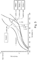
- Fig. 3 is a graph showing the results of thermo-gravimetric tests using a Setaram Setsys instrument operating in dry Air and a temperature ramp rate of 1 K min -1 to ensure equilibrium conditions.
- the samples were ground gamma-TiAl disks with diameter of 15 mm and thickness of 1 mm suspended through a 1 mm diameter hole near the edge of the sample.
- Thermogravimetric tests were performed on four different samples provided with different coatings, along with a result for an uncoated ⁇ -TiAl substrate.
- the different samples were provided with different coatings.
- the coating of 'strategy 1' comprised alternating layers of CrAlYN and CrN with a bilayer thickness of 2.7 nm, with a composition of Cr 19 at.%, Al 29 at.%, Y 2 at.%, and N 50 at.%.
- the coating of 'strategy 2' comprised alternating layers of CrAlYN and AISiN with a bilayer thickness of 2.9 nm, with a composition of Cr 14 at.%, Al 22 at.%, Y 2 at.%, Si 12 at.%, and N 50 at.%.
- the coating of 'strategy 3' comprised alternating layers of CrAlBYN and AISiN with a bilayer thickness of 2.6 nm, with a composition of Cr 12 at.%, Al 19 at.%, Y 2 at.%, Si 12 at.%, B 5 at.%, and N 50 at.%.
- the coating of 'strategy 4' comprised alternating layers of CrAlBY and AISi with a bilayer thickness of 5.2 nm with a composition of Cr 24 at.%, Al 38 at.%, Y 4 at.%, Si 24 at.%, and B 10 at.%.
- Fig. 3 illustrates that all the coatings give an improvement (i.e. reduction in mass gain) compared to the uncoated sample. Moreover, all the strategies comprising metallic nitride alternating layers performed better than strategy 4, which did not. Nonetheless, strategy 4, comprising B and Si in the alternating layers, still provides an improvement compared to the uncoated sample.
- strategy 1 involves no B or Si in the alternating layers.
- the improvements at high temperature are particularly marked, which provides benefits for components such as gas turbine aerofoils which operate at high temperatures.
- Fig. 4 is a micrograph of the surface of the strategy 1 sample after the thermo-gravimetric test.
- Fig. 5 is a micrograph of the surface of the strategy 3 sample after the thermo-gravimetric test.
- the strategy 1 sample shows undesirable cracks and substrate oxides in the coating.
- the strategy 3 sample shows no cracking or substrate oxides confirming that it remains as a good diffusion barrier, as expected from the thermo-gravimetric test. It is expected that similar results would be observed for other substrate metals or metal alloys such as a high speed steel, other TiAl based alloys or Ni based alloys.
- the process conditions used to create distinct layers at the nanoscale provide improved physical properties by exploiting the superlattice effect.
- the bilayer thickness allows for shearing to generate dislocations within the layers, but the dislocations are prevented from crossing the layer boundaries, and thus prevented from moving. This leads to increased hardness. At greater thicknesses the interaction between layers is reduced, and dislocations can propagate through the layers, reducing hardness. At smaller thicknesses, dislocations are prevented from forming at all.
- the different elements of the coatings provided different advantages that, when combined, contribute to the observed performance of the coatings.
- Cr, Al, and Si are known to form dense oxide scales which provide better protection against oxygen inward diffusion. Dense oxides react slower with the aggressive molten salts such as Na 2 SO 4 , NaCl as well as V 2 O 5 and SO 2 produced by burning aviation fuel. Therefore it is believed that the inclusion of these elements helps achieve longer protection against hot corrosion attack.
- Yttrium has a high affinity for oxygen, and thus produces stable oxide at high temperatures. It is believed that its inclusion improves oxide scale adhesion to the substrate and reduces oxide scale spallation.
Landscapes
- Chemical & Material Sciences (AREA)
- Engineering & Computer Science (AREA)
- Mechanical Engineering (AREA)
- Materials Engineering (AREA)
- Organic Chemistry (AREA)
- Metallurgy (AREA)
- Chemical Kinetics & Catalysis (AREA)
- Inorganic Chemistry (AREA)
- General Engineering & Computer Science (AREA)
- Ceramic Engineering (AREA)
- Physics & Mathematics (AREA)
- Plasma & Fusion (AREA)
- Analytical Chemistry (AREA)
- Physical Vapour Deposition (AREA)
- Turbine Rotor Nozzle Sealing (AREA)
Abstract
Description
- The present disclosure concerns a coated substrate, and in particular a coating for improving oxidation resistance of gas turbine aerofoils.
- Titanium aluminide aerofoils, such as those found in gas turbine engines, operate in a high temperature environment that encourages oxidation and corrosion. This is detrimental to the integrity of the parts. To mitigate against such oxidation and corrosion, coating systems have been proposed. In these systems, coatings can be applied to the part to be protected by physical vapour deposition (PVD) methods.
- However, such coatings may themselves reduce the integrity of the system due to their brittle nature, or may only provide limited ability to withstand the diffusion of corrosive species into the underlying substrate. Often coatings only have limited temperature durability before excessive oxidation of the substrate is seen. Moreover, surface cracking has been observed to occur during exposure to high temperatures.
- Therefore, there remains a problem of how to provide a substrate coating that can provide an effective oxidation protection whilst also enduring the physical rigours of high temperature environments.
- High power impulse magnetron sputtering (HIPIMS) is a known PVD technique -
GB 2,450,950 GB 2,450,950 - The present inventors have identified that that the use of HIPIMS for coating aerofoils can be more advantageous that alternative PVD processes. HIPIMS can produce a higher density coating than alternative PVD processes. The higher density achieved minimises intercolumnar porosity in the coating, which is a pathway for corrosive species to transport through the coating from the environment and attack the substrate. Moreover, HIPIMS can be used to provide a coating architecture that consists of a plurality of layers that provide an effective barrier, through multiple interfaces to oxidation and corrosive species and which improves coating toughness. In particular, the multilayer interfaces produced by HIPIMS are very sharp and flat. This makes them particularly effective as a barrier to diffusion due to the limited atomic misfit.
- The inventors have also identified particular compositions of coating that are effective. By selecting particular elements for use in the coating layers, the coating can be controlled to a) form a dense oxide scale that inhibits further oxidation and corrosion and b) to stabilise the oxide scale to prevent it spalling off and exposing unreacted coating or substrate. It is believed that cracking in prior art coatings is due to tensile stress exerted on the coating by the difference in thermal expansion coefficients of the coating and the substrate. This cracking produces fatigue deficit and reduces the effectiveness of the coating for inhibiting further oxidation and corrosion. The inventors have identified particular compositions that can at least partially mitigate these issues.
- According to one aspect, the present invention provides a coated substrate comprising a metal or metal alloy such as a high speed steel, TiAl based alloy or Ni based alloy or an electrically conductive ceramic material, wherein the coating comprises a hard material protective coating comprising alternating layers of different compositions, wherein a first composition of the alternating layers comprises silicon, Si, and/or a second composition of the alternating layers comprises boron, B. Such coatings exhibit improved protection in terms of oxidation resistance and cracking. The provision of the alternating layers comprising Si and B is believed to inhibit the fast diffusion of oxygen along grain boundaries.
- The first composition of the alternating layers may comprise aluminium and silicon. Additionally or alternatively, the second composition of the alternating layers may comprise aluminium and boron. For example, the first composition of the alternating layers may comprise AISi, and/or the second composition of the alternating layers may comprise AIB.
- Optionally, the layers comprising silicon are silicon containing metallic nitride layers, such as TiAlSiN, CrAISiN, AISiN, ZrAlSiN, TiAlSiYN, CrAlSiYN, AlSiYN, ZrAlSiYN.
- Optionally, the layers comprising silicon contain 0.5 to 30 at% Si.
- Optionally, the layers comprising boron are boron containing metallic nitride layers also comprising a proportion of one or more rare earth elements such as ytrrium, for example TiAlCrBYN, CrAlBYN, ZrCrAlBYN, TiAlCrBN, CrAlBN or ZrCrAIBN.
- Optionally, the layers comprising boron comprise 0.1 to 20 at% B.
- Optionally, a bilayer thickness of the alternating layers is in the range of 1 to 20 nm, preferably within the range of 2 to 5 nm. It is believed that this range of thicknesses exploits the superlattice effect to provide improved physical properties to the coatings.
- Optionally, the coated substrate further comprises an interface layer adjacent to the substrate which is a nitrogen free intermetallic layer containing a proportion of one or more rare earth elements, optionally yttrium.
- Optionally, the substrate is an aerofoil for a gas turbine engine.
- According to a second aspect of the invention, there is provided a gas turbine aerofoil comprising a hard material protective HIPIMS coating. A HIPIMS coating is denser than that of alternative PVD processes, and the multilayer interfaces produced by HIPIMS are very sharp and flat. This makes HIPIMS coatings particularly effective as a barrier to diffusion due to their dense grain boundaries.
- According to a third aspect of the invention, there is provided a gas turbine engine comprising a coated substrate of the first aspect, wherein the substrate is an aerofoil, or a gas turbine aerofoil according to the second aspect.
- According to a fourth aspect of the invention, there is provided a method for the manufacture of a hard material protective coating on a substrate comprising a metal or metal alloy such as a high speed steel, a TiAl based alloy or an Ni based alloy or an electrically conductive ceramic material, the method comprising: depositing alternating layers of different compositions, wherein a first composition of the alternating layers comprises silicon, Si, and/or a second composition of the alternating layers comprises boron, B.
- Optionally, the deposition can be performed by any one of HIPIMS coating, arc vaporization coating and magnetron sputtering.
- Optionally, the alternating layers have a bilayer thickness in the range of 1 to 20 nm, preferably within the range of 2 to 5 nm.
- Optionally a strength of a horizontal component of a magnetic field in front of the deposition target is preferably in the range of from 100 to 1500 Gauss, more preferably 200 to 1000 Gauss, and still more preferably 300 to 500 Gauss and most preferably around 400 Gauss.
- According to a fifth aspect of the invention there is provided the use of HIPIMS to provide a gas turbine aerofoil with a hard material protective coating.
- The skilled person will appreciate that except where mutually exclusive, a feature described in relation to any one of the above aspects may be applied mutatis mutandis to any other aspect. Furthermore except where mutually exclusive any feature described herein may be applied to any aspect and/or combined with any other feature described herein.
- Embodiments will now be described by way of example only, with reference to the Figures, in which:
-
Figure 1 is a sectional side view of a gas turbine engine; -
Figure 2 is a schematic cross-section of a layered coating on a substrate; -
Figure 3 is a graph showing the results of thermo-gravimetric tests; -
Figure 4 is a micrograph of a coating following a thermo-gravimetric test; and -
Figure 5 is a micrograph of another coating following a thermo-gravimetric test. - With reference to
Figure 1 , a gas turbine engine is generally indicated at 10, having a principal androtational axis 11. Theengine 10 comprises, in axial flow series, anair intake 12, apropulsive fan 13, anintermediate pressure compressor 14, a high-pressure compressor 15,combustion equipment 16, a high-pressure turbine 17, anintermediate pressure turbine 18, a low-pressure turbine 19 and anexhaust nozzle 20. Anacelle 21 generally surrounds theengine 10 and defines both theintake 12 and theexhaust nozzle 20. - The
gas turbine engine 10 works in the conventional manner so that air entering theintake 12 is accelerated by thefan 13 to produce two air flows: a first air flow into theintermediate pressure compressor 14 and a second air flow which passes through abypass duct 22 to provide propulsive thrust. Theintermediate pressure compressor 14 compresses the airflow directed into it before delivering that air to thehigh pressure compressor 15 where further compression takes place. - The compressed air exhausted from the high-
pressure compressor 15 is directed into thecombustion equipment 16 where it is mixed with fuel and the mixture combusted. The resultant hot combustion products then expand through, and thereby drive the high, intermediate and low-pressure turbines nozzle 20 to provide additional propulsive thrust. The high 17, intermediate 18 and low 19 pressure turbines drive respectively thehigh pressure compressor 15,intermediate pressure compressor 14 andfan 13, each by suitable interconnecting shaft. - Other gas turbine engines to which the present disclosure may be applied may have alternative configurations. By way of example such engines may have an alternative number of interconnecting shafts (e.g. two) and/or an alternative number of compressors and/or turbines. Further the engine may comprise a gearbox provided in the drive train from a turbine to a compressor and/or fan.
- The high 17, intermediate 18 and low 19 pressure turbines have aerofoils that typically comprise titanium aluminide or the like.
- A system for coating a TiAl based alloy substrate, or other substrate such as a high speed steel, Ni based alloy or an electrically conductive ceramic material, will now be discussed with reference to
Fig. 2 . - The coated substrate 30 of
Fig. 2 comprisessubstrate layer 31 with alternating coating layers 34, 35. There may also be aninterface layer 32 andbase layer 33. Such a structure can be produced following a modified technique based uponGB 2,450,950 - The alternating layers 34, 35 preferably comprise alternating layers of different compositions. Preferably the layers alternately comprise silicon, Si, and boron, B. That is, alternate ones of the layers comprise silicon but essentially no boron, whilst the other layers comprise boron but essentially no silicon. However, the coating may include alternating and different compositions in which one composition comprises silicon whilst the other composition comprises essentially no silicon, without necessarily also comprising boron. Similarly the coating may include two alternating and different compositions in which one composition comprises boron whilst the other composition comprises essentially no boron, without necessarily also comprising silicon.
- The alternating layers may be: Si or B containing metallic layers, such as AISi; or Si or B containing metallic layers that also comprise a proportion of one or more rare earth elements such as yttrium, such as CrAlBY; or Si or B containing metallic nitride layers, such as TiAlSiN, CrAlSiN, ZrAlSiN, AISiN, TiAIBN, CrAlBN, ZrAIBN or AIBN; or Si or B containing metallic nitride layers that also comprise a proportion of one or more rare earth elements such as yttrium, for example TiAlCrBYN, CrAlBYN, TiAlCrSiYN, CrAlSiYN. Other rare earth metals could also be substituted for yttrium, for example Sc, La or Ce. Where one set of alternating layers does not comprise Si or B, they may comprise a metallic nitride such as CrN, CrAIN or CrAlYN.
- Silicon may be present in a composition of the alternating layers in the range of 0.5-30 at.%, optionally 5-25 at.%, further optionally 10-15 at.%, and preferably about 12 at.%. Boron may be present in a composition of the alternating layers in the range of 0.1 - 10 at.%, optionally 2 - 8 at.%, further optionally 4 - 6 at.%, and preferably about 5 at.%. Yttrium may be present in a composition of the alternating layers in the range of 0.1-10 at.%, optionally 0.5 - 6 at.%, further optionally 1 - 3 at.%, and preferably about 2 at.%. Chromium may be present in one or more compositions of the alternating layers in the range of 20-80 at.%; and aluminium may be present in one or more compositions of the alternating layers in the range of 20-80 at.%.
- The alternating layers 34, 35 may be produced by any physical vapour deposition (PVD) method, such as HIPIMS coating, arc vaporization coating and direct current magnetron sputtering (DCMS). However, HIPIMS coating, or a combination of a HIPIMS source with, e.g. three, DCMS sources, is preferred as this can provide sharp and flat interfaces between the alternating layers, and this is believed to contribute to their effectiveness as a barrier coating. HIPIMS can provide distinct layers at the nanoscale, preferably with a bilayer thickness (i.e. the thickness of two adjacent layers of different composition) of 1 to 20 nm, and more preferably within the range of 2 to 5 nm.
- During the deposition, the strength of the horizontal component of the magnetic field in front of the deposition target is preferably in the range of from 100 to 1500 Gauss, more preferably 200 to 1000 Gauss, and still more preferably 300 to 500 Gauss and most preferably around 400 Gauss.
- During the deposition, the power density of the HIPIMS pulse discharge is preferably more than 50 W/cm2, more preferably more than 200 W/cm2 and still more preferably 300 W/cm2 or more.
- During the deposition, the HIPIMS pulse duration is preferably in the range of from 10 to 10,000 µs, more preferably from 40 to 1,000 µs, still more preferably from 60 to 100 µs, and most preferably around 80 µs.
- During the deposition, the HIPIMS pulse interval is preferably in the range of from 0.2 milliseconds to 1000 s, more preferably from 1 ms to 1 s, still more preferably from 1.5 to 500 ms, and even more preferably around 2.5 ms.
- The
interface layer 32 andbase layer 33 serve to bind the alternatinglayers substrate 31. In particular, theinterface layer 32 adjacent to thesubstrate 31 can be a nitrogen free intermetallic layer containing a proportion of one or more rare earth elements. Yttrium, in particular, may be used in the interface layer, preferably in the range of 0.1-10 at.%. The interface layer may further optionally contain other elements, such as boron. - The
base layer 33 may have the same composition as one of the alternating layers, but have a greater thickness to assist with adhering the alternating layers to theunderlying substrate 31 and/orinterface 33. For example the base layer may be the same composition as the boron containing alternating layers. -
Fig. 3 is a graph showing the results of thermo-gravimetric tests using a Setaram Setsys instrument operating in dry Air and a temperature ramp rate of 1 K min-1 to ensure equilibrium conditions. The samples were ground gamma-TiAl disks with diameter of 15 mm and thickness of 1 mm suspended through a 1 mm diameter hole near the edge of the sample. Thermogravimetric tests were performed on four different samples provided with different coatings, along with a result for an uncoated γ-TiAl substrate. - The samples were produced following the methodology of
GB 2,450,950 - one HIPIMS source was used and three conventional direct current magnetron sputtering (DCMS) sources;
- the strength of the horizontal component of the magnetic field in front of the target was around 400 Gauss;
- the power density of the HIPIMS pulse discharge was around 300 W/cm2;
- the HIPIMS pulse duration was around 80 µs;
- the HIPIMS pulse interval was 2.5 milliseconds
- the temperature of deposition was around 400°C throughout the process.
- The different samples were provided with different coatings. The coating of 'strategy 1' comprised alternating layers of CrAlYN and CrN with a bilayer thickness of 2.7 nm, with a composition of
Cr 19 at.%, Al 29 at.%,Y 2 at.%, and N 50 at.%. The coating of 'strategy 2' comprised alternating layers of CrAlYN and AISiN with a bilayer thickness of 2.9 nm, with a composition ofCr 14 at.%,Al 22 at.%,Y 2 at.%,Si 12 at.%, and N 50 at.%. The coating of 'strategy 3' comprised alternating layers of CrAlBYN and AISiN with a bilayer thickness of 2.6 nm, with a composition ofCr 12 at.%,Al 19 at.%,Y 2 at.%,Si 12 at.%, B 5 at.%, and N 50 at.%. The coating of 'strategy 4' comprised alternating layers of CrAlBY and AISi with a bilayer thickness of 5.2 nm with a composition of Cr 24 at.%,Al 38 at.%,Y 4 at.%, Si 24 at.%, andB 10 at.%. -
Fig. 3 illustrates that all the coatings give an improvement (i.e. reduction in mass gain) compared to the uncoated sample. Moreover, all the strategies comprising metallic nitride alternating layers performed better thanstrategy 4, which did not. Nonetheless,strategy 4, comprising B and Si in the alternating layers, still provides an improvement compared to the uncoated sample. - Also, a surprising difference can be observed between the improvements achieved with the coatings of
strategies strategy 1. These strategies all involve alternating nitride layers, butstrategy 1 involves no B or Si in the alternating layers. The improvements at high temperature are particularly marked, which provides benefits for components such as gas turbine aerofoils which operate at high temperatures. -
Fig. 4 is a micrograph of the surface of thestrategy 1 sample after the thermo-gravimetric test.Fig. 5 is a micrograph of the surface of thestrategy 3 sample after the thermo-gravimetric test. As can be seen from these two figures, thestrategy 1 sample shows undesirable cracks and substrate oxides in the coating. In contrast, thestrategy 3 sample shows no cracking or substrate oxides confirming that it remains as a good diffusion barrier, as expected from the thermo-gravimetric test. It is expected that similar results would be observed for other substrate metals or metal alloys such as a high speed steel, other TiAl based alloys or Ni based alloys. - Without wishing to be bound by theory, it is believed that the process conditions used to create distinct layers at the nanoscale, with a bilayer thickness of 1 to 20 nm, and more preferably within the range of 2 to 5 nm, provide improved physical properties by exploiting the superlattice effect. The bilayer thickness allows for shearing to generate dislocations within the layers, but the dislocations are prevented from crossing the layer boundaries, and thus prevented from moving. This leads to increased hardness. At greater thicknesses the interaction between layers is reduced, and dislocations can propagate through the layers, reducing hardness. At smaller thicknesses, dislocations are prevented from forming at all.
- Still without wishing to be bound by theory, it is believed that the different elements of the coatings provided different advantages that, when combined, contribute to the observed performance of the coatings. Cr, Al, and Si are known to form dense oxide scales which provide better protection against oxygen inward diffusion. Dense oxides react slower with the aggressive molten salts such as Na2SO4, NaCl as well as V2O5 and SO2 produced by burning aviation fuel. Therefore it is believed that the inclusion of these elements helps achieve longer protection against hot corrosion attack. Yttrium has a high affinity for oxygen, and thus produces stable oxide at high temperatures. It is believed that its inclusion improves oxide scale adhesion to the substrate and reduces oxide scale spallation. Also, by including Yttrium, with its larger atom, in the interface between the substrate and the layered coating, it is thought that a tolerable level of compressive stress is produced in the interface which can hinder fatigue crack formation. Boron in small amounts in bulk Ti-based alloys can improve their ductility, and so it is believed the inclusion of Boron can help reduce cracking in the coatings due to mismatch in thermal expansion coefficients, as well as to reduce crack formation probability in the coated substrate under cyclic (fatigue) load conditions. Borides also show high resistance against hot corrosion. Moreover, all of Cr, Al, Si, Y and B are relatively light elements with small atomic radius, which means that they have high ad-atom mobility in conditions of ion assisted deposition on a condensation surface. This is believed to improve coating density. It is also believed that is advantageous to have elements such as B and Si at grain boundaries to inhibit the fast diffusion of oxygen along these pathways. By the sequential delivery of these elements from alternating sputtering targets, multiple sharp barriers to diffusion and dislocation movement can be provided.
- It will be understood that the invention is not limited to the embodiments above-described and various modifications and improvements can be made without departing from the concepts described herein. Except where mutually exclusive, any of the features may be employed separately or in combination with any other features and the disclosure extends to and includes all combinations and subcombinations of one or more features described herein.
Claims (15)
- A coated substrate comprising a metal or metal alloy such as a high speed steel, TiAl based alloy or Ni based alloy or an electrically conductive ceramic material, wherein the coating comprises a hard material protective coating comprising alternating layers of different compositions, wherein a first composition of the alternating layers comprises silicon, Si, and/or a second composition of the alternating layers comprises boron, B.
- The coated substrate according to claim 1, wherein the layers comprising silicon are silicon containing metallic nitride layers, such as TiAlSiN, CrAlSiN, AISiN.
- The coated substrate according to claim 1 or claim 2, wherein the layers comprising silicon contain 0.5 to 30 at% Si.
- The coated substrate according to any of the preceding claims, wherein the layers comprising boron are boron containing metallic nitride layers also comprising a proportion of one or more rare earth elements such as TiAlCrBYN, CrAlBYN.
- The coated substrate according to any of the preceding claims, wherein the layers comprising boron comprise 0.1 to 20 at% B.
- The coated substrate according to any of the preceding claims, wherein the first composition of the alternating layers comprises aluminium and silicon and/or the second composition of the alternating layers comprises aluminium and boron.
- The coated substrate according to any of the preceding claims, wherein a bilayer thickness of the alternating layers is in the range of 1 to 20 nm, preferably within the range of 2 to 5 nm.
- The coated substrate according to any of the preceding claims, further comprising an interface layer adjacent to the substrate which is a nitrogen free intermetallic layer containing a proportion of one or more rare earth elements, optionally yttrium.
- The coated substrate according to any of the preceding claims, wherein the substrate is an aerofoil for a gas turbine engine.
- A gas turbine engine comprising a coated substrate according to claim 9.
- A method for the manufacture of a hard material protective coating on a substrate comprising a metal or metal alloy such as a high speed steel, a TiAl based alloy or an Ni based alloy or an electrically conductive ceramic material, the method comprising:depositing alternating layers of different compositions, wherein a first composition of the alternating layers comprises silicon, Si, and/or a second composition of the alternating layers comprises boron, B.
- The method according to claim 11, wherein the deposition is performed by any one of HIPIMS coating, arc vaporization coating and magnetron sputtering.
- The method according to claim 11 or 12, wherein the alternating layers have a bilayer thickness in the range of 1 to 20 nm, preferably within the range of 2 to 5 nm.
- The method according to any of claims 11 to 13, wherein a strength of a horizontal component of a magnetic field in front of the deposition target is preferably in the range of from 100 to 1500 Gauss, more preferably 200 to 1000 Gauss, and still more preferably 300 to 500 Gauss and most preferably around 400 Gauss.
- The method according to any of claims 11 to 14, wherein the first composition of the alternating layers comprises aluminium and silicon and/or the second composition of the alternating layers comprises aluminium and boron.
Applications Claiming Priority (1)
| Application Number | Priority Date | Filing Date | Title |
|---|---|---|---|
| GBGB1802468.7A GB201802468D0 (en) | 2018-02-15 | 2018-02-15 | Coated substrate |
Publications (2)
| Publication Number | Publication Date |
|---|---|
| EP3527688A1 true EP3527688A1 (en) | 2019-08-21 |
| EP3527688B1 EP3527688B1 (en) | 2023-05-17 |
Family
ID=61783894
Family Applications (1)
| Application Number | Title | Priority Date | Filing Date |
|---|---|---|---|
| EP19152154.1A Active EP3527688B1 (en) | 2018-02-15 | 2019-01-16 | Coated substrate |
Country Status (4)
| Country | Link |
|---|---|
| US (1) | US11131016B2 (en) |
| EP (1) | EP3527688B1 (en) |
| CN (1) | CN110158030A (en) |
| GB (1) | GB201802468D0 (en) |
Families Citing this family (5)
| Publication number | Priority date | Publication date | Assignee | Title |
|---|---|---|---|---|
| US11008650B2 (en) * | 2016-11-03 | 2021-05-18 | Starfire Industries Llc | Compact system for coupling RF power directly into RF linacs |
| US12009192B2 (en) * | 2016-11-03 | 2024-06-11 | Starfire Industries Llc | System for coupling RF power into LINACs and bellows coating by magnetron sputtering with kick pulse |
| CN113667929B (en) * | 2021-07-02 | 2023-04-07 | 株洲钻石切削刀具股份有限公司 | Periodic multilayer coating cutter and preparation method thereof |
| CN116949399B (en) * | 2023-07-03 | 2025-10-31 | 岭南师范学院 | Coating structure for rotary tillage cutter and preparation method thereof |
| CN118407044B (en) * | 2024-03-14 | 2025-10-17 | 广东工业大学 | CrAlBYN-containing composite coating cutter and preparation method thereof |
Citations (5)
| Publication number | Priority date | Publication date | Assignee | Title |
|---|---|---|---|---|
| US5283109A (en) * | 1991-04-15 | 1994-02-01 | Ultramet | High temperature resistant structure |
| JP3239505B2 (en) * | 1993-01-13 | 2001-12-17 | 石川島播磨重工業株式会社 | Mounting method of thin film sensor |
| US20080003418A1 (en) * | 2006-06-30 | 2008-01-03 | Kabushiki Kaisha Kobe Seiko Sho (Kobe Steel, Ltd.) | Hard film and method of manufacturing the same |
| GB2450950A (en) | 2007-07-13 | 2009-01-14 | Hauzer Techno Coating Bv | Method of providing a hard coating |
| US20170204871A1 (en) * | 2014-12-25 | 2017-07-20 | Ihi Corporation | Compressor vane or blade for engine |
Family Cites Families (12)
| Publication number | Priority date | Publication date | Assignee | Title |
|---|---|---|---|---|
| CN100419117C (en) * | 2004-02-02 | 2008-09-17 | 株式会社神户制钢所 | Hard laminated film, method for producing same, and film forming apparatus |
| EP1783245B1 (en) * | 2005-11-04 | 2018-01-24 | Oerlikon Surface Solutions AG, Pfäffikon | Tool or wear part and pvd coating method to deposit a surface coating on a tool or wear part |
| JP4950499B2 (en) * | 2006-02-03 | 2012-06-13 | 株式会社神戸製鋼所 | Hard coating and method for forming the same |
| EP2149624B1 (en) | 2008-07-31 | 2012-08-08 | Sulzer Metaplas GmbH | Multilayer film-coated member and method for producing it |
| US20100226783A1 (en) * | 2009-03-06 | 2010-09-09 | General Electric Company | Erosion and Corrosion Resistant Turbine Compressor Airfoil and Method of Making the Same |
| CN104126025B (en) | 2011-12-15 | 2016-08-24 | 株式会社神户制钢所 | Multilayer hard epithelium and preparation method thereof |
| KR101823893B1 (en) * | 2012-10-04 | 2018-01-31 | 현대자동차주식회사 | Coating material for exhaust system and the method for manufacturing thereof |
| JP6491031B2 (en) * | 2014-06-24 | 2019-03-27 | 株式会社神戸製鋼所 | Laminated hard coating and cutting tool |
| EP3018233A1 (en) * | 2014-11-05 | 2016-05-11 | Walter Ag | Cutting tool with multilayer PVD coating |
| KR101743019B1 (en) | 2015-01-30 | 2017-06-05 | 한국과학기술연구원 | High temperature oxidation resistant boron carbide thin film, cutting tools using the thin film and method of manufacturing the same |
| CN105256273A (en) | 2015-11-08 | 2016-01-20 | 宜昌后皇真空科技有限公司 | Nitrogen boron titanium/ nitrogen silicon aluminum titanium nanometer composite multilayer coating cutter and preparation method thereof |
| CN107523790B (en) * | 2017-07-05 | 2019-08-27 | 广东工业大学 | A kind of AlCrSiCuN nanometer multi-layer coating and preparation method thereof |
-
2018
- 2018-02-15 GB GBGB1802468.7A patent/GB201802468D0/en not_active Ceased
-
2019
- 2019-01-16 EP EP19152154.1A patent/EP3527688B1/en active Active
- 2019-01-17 US US16/250,471 patent/US11131016B2/en active Active
- 2019-02-15 CN CN201910116587.5A patent/CN110158030A/en active Pending
Patent Citations (5)
| Publication number | Priority date | Publication date | Assignee | Title |
|---|---|---|---|---|
| US5283109A (en) * | 1991-04-15 | 1994-02-01 | Ultramet | High temperature resistant structure |
| JP3239505B2 (en) * | 1993-01-13 | 2001-12-17 | 石川島播磨重工業株式会社 | Mounting method of thin film sensor |
| US20080003418A1 (en) * | 2006-06-30 | 2008-01-03 | Kabushiki Kaisha Kobe Seiko Sho (Kobe Steel, Ltd.) | Hard film and method of manufacturing the same |
| GB2450950A (en) | 2007-07-13 | 2009-01-14 | Hauzer Techno Coating Bv | Method of providing a hard coating |
| US20170204871A1 (en) * | 2014-12-25 | 2017-07-20 | Ihi Corporation | Compressor vane or blade for engine |
Non-Patent Citations (2)
| Title |
|---|
| LEMBKE ET AL.: "Significance of Y and Cr in TiAIN hard coatings for dry high speed cutting", SURFACE ENGINEERING, vol. 17, no. 2, 2001, pages 153 - 158 |
| P. EH. HOVSEPIAN; C. REINHARD; A.P. EHIASARIAN: "CrAIYN/CrN superlattice coatings deposited by the combined high power impulse magnetron sputtering/unbalanced magnetron sputtering technique", SURFACE AND COATINGS TECHNOLOGY, vol. 201, 2006, pages 4105 - 4110 |
Also Published As
| Publication number | Publication date |
|---|---|
| GB201802468D0 (en) | 2018-04-04 |
| US11131016B2 (en) | 2021-09-28 |
| US20190249291A1 (en) | 2019-08-15 |
| CN110158030A (en) | 2019-08-23 |
| EP3527688B1 (en) | 2023-05-17 |
Similar Documents
| Publication | Publication Date | Title |
|---|---|---|
| US11131016B2 (en) | Coated substrate | |
| US6291084B1 (en) | Nickel aluminide coating and coating systems formed therewith | |
| US6153313A (en) | Nickel aluminide coating and coating systems formed therewith | |
| US4339509A (en) | Superalloy coating composition with oxidation and/or sulfidation resistance | |
| EP2145969B1 (en) | Economic oxidation and fatigue resistant metallic coating | |
| TWI228151B (en) | Oxidation and fatigue resistant metallic coating | |
| JP5437573B2 (en) | Alloy compositions and articles containing the same | |
| EP2607510B1 (en) | Nickel-cobalt-based alloy and bond coat and bond coated articles incorporating the same | |
| Streiff | Protection of materials by advanced high temperature coatings | |
| US20100028711A1 (en) | Thermal barrier coatings and methods of producing same | |
| KR20070077056A (en) | Cmas resistant thermal barrier coating | |
| Kablov et al. | Erosion-resistant coatings for gas turbine engine compressor blades | |
| JPH10219476A (en) | Ceramic coated gas turbine blade | |
| US20140030497A1 (en) | Localized transitional coating of turbine components | |
| EP2628825A1 (en) | Coated article and process of coating an article | |
| US20050079370A1 (en) | Nano-multilayered structures, components and associated methods of manufacture | |
| US6635124B1 (en) | Method of depositing a thermal barrier coating | |
| US7981520B2 (en) | Oxide-forming protective coatings for niobium-based materials | |
| Immarigeon et al. | Erosion testing of coatings for aero engine compressor components | |
| JP2007092169A (en) | Nickel aluminide coating containing gamma prime phase | |
| EP1391533B1 (en) | Method for protecting articles, and related compositions | |
| Bogdanovich et al. | Analysis of the ceramic layer microstructure influence on plasma spray thermal barrier coating performance | |
| Gupta et al. | A silicon and hafnium modified plasma sprayed MCrAlY coating | |
| Podchernyaeva et al. | Protective coatings on heat-resistant nickel alloys | |
| US6749951B1 (en) | Coated article having a quasicrystalline-ductile metal layered coating with high wear resistance, and its preparation and use |
Legal Events
| Date | Code | Title | Description |
|---|---|---|---|
| PUAI | Public reference made under article 153(3) epc to a published international application that has entered the european phase |
Free format text: ORIGINAL CODE: 0009012 |
|
| STAA | Information on the status of an ep patent application or granted ep patent |
Free format text: STATUS: THE APPLICATION HAS BEEN PUBLISHED |
|
| AK | Designated contracting states |
Kind code of ref document: A1 Designated state(s): AL AT BE BG CH CY CZ DE DK EE ES FI FR GB GR HR HU IE IS IT LI LT LU LV MC MK MT NL NO PL PT RO RS SE SI SK SM TR |
|
| AX | Request for extension of the european patent |
Extension state: BA ME |
|
| RAP1 | Party data changed (applicant data changed or rights of an application transferred) |
Owner name: ROLLS-ROYCE PLC |
|
| STAA | Information on the status of an ep patent application or granted ep patent |
Free format text: STATUS: REQUEST FOR EXAMINATION WAS MADE |
|
| 17P | Request for examination filed |
Effective date: 20200220 |
|
| RBV | Designated contracting states (corrected) |
Designated state(s): AL AT BE BG CH CY CZ DE DK EE ES FI FR GB GR HR HU IE IS IT LI LT LU LV MC MK MT NL NO PL PT RO RS SE SI SK SM TR |
|
| STAA | Information on the status of an ep patent application or granted ep patent |
Free format text: STATUS: EXAMINATION IS IN PROGRESS |
|
| 17Q | First examination report despatched |
Effective date: 20220303 |
|
| REG | Reference to a national code |
Ref legal event code: R079 Free format text: PREVIOUS MAIN CLASS: C23C0014060000 Ipc: C23C0014340000 Ref country code: DE Ref legal event code: R079 Ref document number: 602019028993 Country of ref document: DE Free format text: PREVIOUS MAIN CLASS: C23C0014060000 Ipc: C23C0014340000 |
|
| RIC1 | Information provided on ipc code assigned before grant |
Ipc: H01J 37/34 20060101ALI20221222BHEP Ipc: C23C 28/04 20060101ALI20221222BHEP Ipc: C23C 28/00 20060101ALI20221222BHEP Ipc: F01D 5/28 20060101ALI20221222BHEP Ipc: C23C 14/06 20060101ALI20221222BHEP Ipc: C23C 14/35 20060101ALI20221222BHEP Ipc: C23C 14/34 20060101AFI20221222BHEP |
|
| GRAP | Despatch of communication of intention to grant a patent |
Free format text: ORIGINAL CODE: EPIDOSNIGR1 |
|
| STAA | Information on the status of an ep patent application or granted ep patent |
Free format text: STATUS: GRANT OF PATENT IS INTENDED |
|
| INTG | Intention to grant announced |
Effective date: 20230217 |
|
| GRAS | Grant fee paid |
Free format text: ORIGINAL CODE: EPIDOSNIGR3 |
|
| GRAA | (expected) grant |
Free format text: ORIGINAL CODE: 0009210 |
|
| STAA | Information on the status of an ep patent application or granted ep patent |
Free format text: STATUS: THE PATENT HAS BEEN GRANTED |
|
| AK | Designated contracting states |
Kind code of ref document: B1 Designated state(s): AL AT BE BG CH CY CZ DE DK EE ES FI FR GB GR HR HU IE IS IT LI LT LU LV MC MK MT NL NO PL PT RO RS SE SI SK SM TR |
|
| REG | Reference to a national code |
Ref country code: GB Ref legal event code: FG4D |
|
| REG | Reference to a national code |
Ref country code: DE Ref legal event code: R096 Ref document number: 602019028993 Country of ref document: DE |
|
| REG | Reference to a national code |
Ref country code: CH Ref legal event code: EP |
|
| REG | Reference to a national code |
Ref country code: IE Ref legal event code: FG4D |
|
| REG | Reference to a national code |
Ref country code: AT Ref legal event code: REF Ref document number: 1568392 Country of ref document: AT Kind code of ref document: T Effective date: 20230615 |
|
| P01 | Opt-out of the competence of the unified patent court (upc) registered |
Effective date: 20230528 |
|
| REG | Reference to a national code |
Ref country code: LT Ref legal event code: MG9D |
|
| REG | Reference to a national code |
Ref country code: NL Ref legal event code: MP Effective date: 20230517 |
|
| REG | Reference to a national code |
Ref country code: AT Ref legal event code: MK05 Ref document number: 1568392 Country of ref document: AT Kind code of ref document: T Effective date: 20230517 |
|
| PG25 | Lapsed in a contracting state [announced via postgrant information from national office to epo] |
Ref country code: SE Free format text: LAPSE BECAUSE OF FAILURE TO SUBMIT A TRANSLATION OF THE DESCRIPTION OR TO PAY THE FEE WITHIN THE PRESCRIBED TIME-LIMIT Effective date: 20230517 Ref country code: PT Free format text: LAPSE BECAUSE OF FAILURE TO SUBMIT A TRANSLATION OF THE DESCRIPTION OR TO PAY THE FEE WITHIN THE PRESCRIBED TIME-LIMIT Effective date: 20230918 Ref country code: NO Free format text: LAPSE BECAUSE OF FAILURE TO SUBMIT A TRANSLATION OF THE DESCRIPTION OR TO PAY THE FEE WITHIN THE PRESCRIBED TIME-LIMIT Effective date: 20230817 Ref country code: NL Free format text: LAPSE BECAUSE OF FAILURE TO SUBMIT A TRANSLATION OF THE DESCRIPTION OR TO PAY THE FEE WITHIN THE PRESCRIBED TIME-LIMIT Effective date: 20230517 Ref country code: ES Free format text: LAPSE BECAUSE OF FAILURE TO SUBMIT A TRANSLATION OF THE DESCRIPTION OR TO PAY THE FEE WITHIN THE PRESCRIBED TIME-LIMIT Effective date: 20230517 Ref country code: AT Free format text: LAPSE BECAUSE OF FAILURE TO SUBMIT A TRANSLATION OF THE DESCRIPTION OR TO PAY THE FEE WITHIN THE PRESCRIBED TIME-LIMIT Effective date: 20230517 |
|
| PG25 | Lapsed in a contracting state [announced via postgrant information from national office to epo] |
Ref country code: RS Free format text: LAPSE BECAUSE OF FAILURE TO SUBMIT A TRANSLATION OF THE DESCRIPTION OR TO PAY THE FEE WITHIN THE PRESCRIBED TIME-LIMIT Effective date: 20230517 Ref country code: PL Free format text: LAPSE BECAUSE OF FAILURE TO SUBMIT A TRANSLATION OF THE DESCRIPTION OR TO PAY THE FEE WITHIN THE PRESCRIBED TIME-LIMIT Effective date: 20230517 Ref country code: LV Free format text: LAPSE BECAUSE OF FAILURE TO SUBMIT A TRANSLATION OF THE DESCRIPTION OR TO PAY THE FEE WITHIN THE PRESCRIBED TIME-LIMIT Effective date: 20230517 Ref country code: LT Free format text: LAPSE BECAUSE OF FAILURE TO SUBMIT A TRANSLATION OF THE DESCRIPTION OR TO PAY THE FEE WITHIN THE PRESCRIBED TIME-LIMIT Effective date: 20230517 Ref country code: IS Free format text: LAPSE BECAUSE OF FAILURE TO SUBMIT A TRANSLATION OF THE DESCRIPTION OR TO PAY THE FEE WITHIN THE PRESCRIBED TIME-LIMIT Effective date: 20230917 Ref country code: HR Free format text: LAPSE BECAUSE OF FAILURE TO SUBMIT A TRANSLATION OF THE DESCRIPTION OR TO PAY THE FEE WITHIN THE PRESCRIBED TIME-LIMIT Effective date: 20230517 Ref country code: GR Free format text: LAPSE BECAUSE OF FAILURE TO SUBMIT A TRANSLATION OF THE DESCRIPTION OR TO PAY THE FEE WITHIN THE PRESCRIBED TIME-LIMIT Effective date: 20230818 |
|
| PG25 | Lapsed in a contracting state [announced via postgrant information from national office to epo] |
Ref country code: FI Free format text: LAPSE BECAUSE OF FAILURE TO SUBMIT A TRANSLATION OF THE DESCRIPTION OR TO PAY THE FEE WITHIN THE PRESCRIBED TIME-LIMIT Effective date: 20230517 |
|
| PG25 | Lapsed in a contracting state [announced via postgrant information from national office to epo] |
Ref country code: SK Free format text: LAPSE BECAUSE OF FAILURE TO SUBMIT A TRANSLATION OF THE DESCRIPTION OR TO PAY THE FEE WITHIN THE PRESCRIBED TIME-LIMIT Effective date: 20230517 |
|
| PG25 | Lapsed in a contracting state [announced via postgrant information from national office to epo] |
Ref country code: SM Free format text: LAPSE BECAUSE OF FAILURE TO SUBMIT A TRANSLATION OF THE DESCRIPTION OR TO PAY THE FEE WITHIN THE PRESCRIBED TIME-LIMIT Effective date: 20230517 Ref country code: SK Free format text: LAPSE BECAUSE OF FAILURE TO SUBMIT A TRANSLATION OF THE DESCRIPTION OR TO PAY THE FEE WITHIN THE PRESCRIBED TIME-LIMIT Effective date: 20230517 Ref country code: RO Free format text: LAPSE BECAUSE OF FAILURE TO SUBMIT A TRANSLATION OF THE DESCRIPTION OR TO PAY THE FEE WITHIN THE PRESCRIBED TIME-LIMIT Effective date: 20230517 Ref country code: EE Free format text: LAPSE BECAUSE OF FAILURE TO SUBMIT A TRANSLATION OF THE DESCRIPTION OR TO PAY THE FEE WITHIN THE PRESCRIBED TIME-LIMIT Effective date: 20230517 Ref country code: DK Free format text: LAPSE BECAUSE OF FAILURE TO SUBMIT A TRANSLATION OF THE DESCRIPTION OR TO PAY THE FEE WITHIN THE PRESCRIBED TIME-LIMIT Effective date: 20230517 Ref country code: CZ Free format text: LAPSE BECAUSE OF FAILURE TO SUBMIT A TRANSLATION OF THE DESCRIPTION OR TO PAY THE FEE WITHIN THE PRESCRIBED TIME-LIMIT Effective date: 20230517 |
|
| REG | Reference to a national code |
Ref country code: DE Ref legal event code: R097 Ref document number: 602019028993 Country of ref document: DE |
|
| PLBE | No opposition filed within time limit |
Free format text: ORIGINAL CODE: 0009261 |
|
| STAA | Information on the status of an ep patent application or granted ep patent |
Free format text: STATUS: NO OPPOSITION FILED WITHIN TIME LIMIT |
|
| 26N | No opposition filed |
Effective date: 20240220 |
|
| PG25 | Lapsed in a contracting state [announced via postgrant information from national office to epo] |
Ref country code: SI Free format text: LAPSE BECAUSE OF FAILURE TO SUBMIT A TRANSLATION OF THE DESCRIPTION OR TO PAY THE FEE WITHIN THE PRESCRIBED TIME-LIMIT Effective date: 20230517 |
|
| PG25 | Lapsed in a contracting state [announced via postgrant information from national office to epo] |
Ref country code: SI Free format text: LAPSE BECAUSE OF FAILURE TO SUBMIT A TRANSLATION OF THE DESCRIPTION OR TO PAY THE FEE WITHIN THE PRESCRIBED TIME-LIMIT Effective date: 20230517 Ref country code: IT Free format text: LAPSE BECAUSE OF FAILURE TO SUBMIT A TRANSLATION OF THE DESCRIPTION OR TO PAY THE FEE WITHIN THE PRESCRIBED TIME-LIMIT Effective date: 20230517 |
|
| PG25 | Lapsed in a contracting state [announced via postgrant information from national office to epo] |
Ref country code: MC Free format text: LAPSE BECAUSE OF FAILURE TO SUBMIT A TRANSLATION OF THE DESCRIPTION OR TO PAY THE FEE WITHIN THE PRESCRIBED TIME-LIMIT Effective date: 20230517 |
|
| PG25 | Lapsed in a contracting state [announced via postgrant information from national office to epo] |
Ref country code: MC Free format text: LAPSE BECAUSE OF FAILURE TO SUBMIT A TRANSLATION OF THE DESCRIPTION OR TO PAY THE FEE WITHIN THE PRESCRIBED TIME-LIMIT Effective date: 20230517 |
|
| REG | Reference to a national code |
Ref country code: CH Ref legal event code: PL |
|
| PG25 | Lapsed in a contracting state [announced via postgrant information from national office to epo] |
Ref country code: LU Free format text: LAPSE BECAUSE OF NON-PAYMENT OF DUE FEES Effective date: 20240116 |
|
| PG25 | Lapsed in a contracting state [announced via postgrant information from national office to epo] |
Ref country code: LU Free format text: LAPSE BECAUSE OF NON-PAYMENT OF DUE FEES Effective date: 20240116 |
|
| PG25 | Lapsed in a contracting state [announced via postgrant information from national office to epo] |
Ref country code: BE Free format text: LAPSE BECAUSE OF NON-PAYMENT OF DUE FEES Effective date: 20240131 |
|
| PG25 | Lapsed in a contracting state [announced via postgrant information from national office to epo] |
Ref country code: CH Free format text: LAPSE BECAUSE OF NON-PAYMENT OF DUE FEES Effective date: 20240131 |
|
| PG25 | Lapsed in a contracting state [announced via postgrant information from national office to epo] |
Ref country code: CH Free format text: LAPSE BECAUSE OF NON-PAYMENT OF DUE FEES Effective date: 20240131 Ref country code: BE Free format text: LAPSE BECAUSE OF NON-PAYMENT OF DUE FEES Effective date: 20240131 |
|
| REG | Reference to a national code |
Ref country code: BE Ref legal event code: MM Effective date: 20240131 |
|
| PG25 | Lapsed in a contracting state [announced via postgrant information from national office to epo] |
Ref country code: BG Free format text: LAPSE BECAUSE OF FAILURE TO SUBMIT A TRANSLATION OF THE DESCRIPTION OR TO PAY THE FEE WITHIN THE PRESCRIBED TIME-LIMIT Effective date: 20230517 |
|
| PG25 | Lapsed in a contracting state [announced via postgrant information from national office to epo] |
Ref country code: BG Free format text: LAPSE BECAUSE OF FAILURE TO SUBMIT A TRANSLATION OF THE DESCRIPTION OR TO PAY THE FEE WITHIN THE PRESCRIBED TIME-LIMIT Effective date: 20230517 |
|
| PG25 | Lapsed in a contracting state [announced via postgrant information from national office to epo] |
Ref country code: IE Free format text: LAPSE BECAUSE OF NON-PAYMENT OF DUE FEES Effective date: 20240116 |
|
| PG25 | Lapsed in a contracting state [announced via postgrant information from national office to epo] |
Ref country code: IE Free format text: LAPSE BECAUSE OF NON-PAYMENT OF DUE FEES Effective date: 20240116 |
|
| PG25 | Lapsed in a contracting state [announced via postgrant information from national office to epo] |
Ref country code: CY Free format text: LAPSE BECAUSE OF FAILURE TO SUBMIT A TRANSLATION OF THE DESCRIPTION OR TO PAY THE FEE WITHIN THE PRESCRIBED TIME-LIMIT; INVALID AB INITIO Effective date: 20190116 |
|
| PG25 | Lapsed in a contracting state [announced via postgrant information from national office to epo] |
Ref country code: HU Free format text: LAPSE BECAUSE OF FAILURE TO SUBMIT A TRANSLATION OF THE DESCRIPTION OR TO PAY THE FEE WITHIN THE PRESCRIBED TIME-LIMIT; INVALID AB INITIO Effective date: 20190116 |
|
| PG25 | Lapsed in a contracting state [announced via postgrant information from national office to epo] |
Ref country code: TR Free format text: LAPSE BECAUSE OF FAILURE TO SUBMIT A TRANSLATION OF THE DESCRIPTION OR TO PAY THE FEE WITHIN THE PRESCRIBED TIME-LIMIT Effective date: 20230517 |
|
| PGFP | Annual fee paid to national office [announced via postgrant information from national office to epo] |
Ref country code: GB Payment date: 20260126 Year of fee payment: 8 |
|
| PGFP | Annual fee paid to national office [announced via postgrant information from national office to epo] |
Ref country code: DE Payment date: 20260127 Year of fee payment: 8 |
|
| PGFP | Annual fee paid to national office [announced via postgrant information from national office to epo] |
Ref country code: FR Payment date: 20260126 Year of fee payment: 8 |