EP3527446A1 - Crankshaft controller - Google Patents
Crankshaft controller Download PDFInfo
- Publication number
- EP3527446A1 EP3527446A1 EP19152195.4A EP19152195A EP3527446A1 EP 3527446 A1 EP3527446 A1 EP 3527446A1 EP 19152195 A EP19152195 A EP 19152195A EP 3527446 A1 EP3527446 A1 EP 3527446A1
- Authority
- EP
- European Patent Office
- Prior art keywords
- crankshaft
- angular
- controller
- internal combustion
- combustion engine
- Prior art date
- Legal status (The legal status is an assumption and is not a legal conclusion. Google has not performed a legal analysis and makes no representation as to the accuracy of the status listed.)
- Granted
Links
Images

Classifications
-
- B—PERFORMING OPERATIONS; TRANSPORTING
- B60—VEHICLES IN GENERAL
- B60W—CONJOINT CONTROL OF VEHICLE SUB-UNITS OF DIFFERENT TYPE OR DIFFERENT FUNCTION; CONTROL SYSTEMS SPECIALLY ADAPTED FOR HYBRID VEHICLES; ROAD VEHICLE DRIVE CONTROL SYSTEMS FOR PURPOSES NOT RELATED TO THE CONTROL OF A PARTICULAR SUB-UNIT
- B60W10/00—Conjoint control of vehicle sub-units of different type or different function
- B60W10/04—Conjoint control of vehicle sub-units of different type or different function including control of propulsion units
- B60W10/06—Conjoint control of vehicle sub-units of different type or different function including control of propulsion units including control of combustion engines
-
- F—MECHANICAL ENGINEERING; LIGHTING; HEATING; WEAPONS; BLASTING
- F02—COMBUSTION ENGINES; HOT-GAS OR COMBUSTION-PRODUCT ENGINE PLANTS
- F02D—CONTROLLING COMBUSTION ENGINES
- F02D41/00—Electrical control of supply of combustible mixture or its constituents
- F02D41/22—Safety or indicating devices for abnormal conditions
-
- F—MECHANICAL ENGINEERING; LIGHTING; HEATING; WEAPONS; BLASTING
- F02—COMBUSTION ENGINES; HOT-GAS OR COMBUSTION-PRODUCT ENGINE PLANTS
- F02D—CONTROLLING COMBUSTION ENGINES
- F02D41/00—Electrical control of supply of combustible mixture or its constituents
- F02D41/009—Electrical control of supply of combustible mixture or its constituents using means for generating position or synchronisation signals
-
- B—PERFORMING OPERATIONS; TRANSPORTING
- B60—VEHICLES IN GENERAL
- B60W—CONJOINT CONTROL OF VEHICLE SUB-UNITS OF DIFFERENT TYPE OR DIFFERENT FUNCTION; CONTROL SYSTEMS SPECIALLY ADAPTED FOR HYBRID VEHICLES; ROAD VEHICLE DRIVE CONTROL SYSTEMS FOR PURPOSES NOT RELATED TO THE CONTROL OF A PARTICULAR SUB-UNIT
- B60W10/00—Conjoint control of vehicle sub-units of different type or different function
- B60W10/04—Conjoint control of vehicle sub-units of different type or different function including control of propulsion units
- B60W10/08—Conjoint control of vehicle sub-units of different type or different function including control of propulsion units including control of electric propulsion units, e.g. motors or generators
-
- B—PERFORMING OPERATIONS; TRANSPORTING
- B60—VEHICLES IN GENERAL
- B60W—CONJOINT CONTROL OF VEHICLE SUB-UNITS OF DIFFERENT TYPE OR DIFFERENT FUNCTION; CONTROL SYSTEMS SPECIALLY ADAPTED FOR HYBRID VEHICLES; ROAD VEHICLE DRIVE CONTROL SYSTEMS FOR PURPOSES NOT RELATED TO THE CONTROL OF A PARTICULAR SUB-UNIT
- B60W20/00—Control systems specially adapted for hybrid vehicles
-
- B—PERFORMING OPERATIONS; TRANSPORTING
- B60—VEHICLES IN GENERAL
- B60W—CONJOINT CONTROL OF VEHICLE SUB-UNITS OF DIFFERENT TYPE OR DIFFERENT FUNCTION; CONTROL SYSTEMS SPECIALLY ADAPTED FOR HYBRID VEHICLES; ROAD VEHICLE DRIVE CONTROL SYSTEMS FOR PURPOSES NOT RELATED TO THE CONTROL OF A PARTICULAR SUB-UNIT
- B60W30/00—Purposes of road vehicle drive control systems not related to the control of a particular sub-unit, e.g. of systems using conjoint control of vehicle sub-units
- B60W30/18—Propelling the vehicle
- B60W30/184—Preventing damage resulting from overload or excessive wear of the driveline
- B60W30/1846—Preventing of breakage of drive line components, e.g. parts of the gearing
-
- B—PERFORMING OPERATIONS; TRANSPORTING
- B60—VEHICLES IN GENERAL
- B60W—CONJOINT CONTROL OF VEHICLE SUB-UNITS OF DIFFERENT TYPE OR DIFFERENT FUNCTION; CONTROL SYSTEMS SPECIALLY ADAPTED FOR HYBRID VEHICLES; ROAD VEHICLE DRIVE CONTROL SYSTEMS FOR PURPOSES NOT RELATED TO THE CONTROL OF A PARTICULAR SUB-UNIT
- B60W30/00—Purposes of road vehicle drive control systems not related to the control of a particular sub-unit, e.g. of systems using conjoint control of vehicle sub-units
- B60W30/18—Propelling the vehicle
- B60W30/192—Mitigating problems related to power-up or power-down of the driveline, e.g. start-up of a cold engine
-
- B—PERFORMING OPERATIONS; TRANSPORTING
- B60—VEHICLES IN GENERAL
- B60W—CONJOINT CONTROL OF VEHICLE SUB-UNITS OF DIFFERENT TYPE OR DIFFERENT FUNCTION; CONTROL SYSTEMS SPECIALLY ADAPTED FOR HYBRID VEHICLES; ROAD VEHICLE DRIVE CONTROL SYSTEMS FOR PURPOSES NOT RELATED TO THE CONTROL OF A PARTICULAR SUB-UNIT
- B60W50/00—Details of control systems for road vehicle drive control not related to the control of a particular sub-unit, e.g. process diagnostic or vehicle driver interfaces
- B60W50/02—Ensuring safety in case of control system failures, e.g. by diagnosing, circumventing or fixing failures
- B60W50/0205—Diagnosing or detecting failures; Failure detection models
-
- F—MECHANICAL ENGINEERING; LIGHTING; HEATING; WEAPONS; BLASTING
- F02—COMBUSTION ENGINES; HOT-GAS OR COMBUSTION-PRODUCT ENGINE PLANTS
- F02N—STARTING OF COMBUSTION ENGINES; STARTING AIDS FOR SUCH ENGINES, NOT OTHERWISE PROVIDED FOR
- F02N11/00—Starting of engines by means of electric motors
- F02N11/04—Starting of engines by means of electric motors the motors being associated with current generators
-
- F—MECHANICAL ENGINEERING; LIGHTING; HEATING; WEAPONS; BLASTING
- F02—COMBUSTION ENGINES; HOT-GAS OR COMBUSTION-PRODUCT ENGINE PLANTS
- F02N—STARTING OF COMBUSTION ENGINES; STARTING AIDS FOR SUCH ENGINES, NOT OTHERWISE PROVIDED FOR
- F02N11/00—Starting of engines by means of electric motors
- F02N11/08—Circuits specially adapted for starting of engines
-
- F—MECHANICAL ENGINEERING; LIGHTING; HEATING; WEAPONS; BLASTING
- F02—COMBUSTION ENGINES; HOT-GAS OR COMBUSTION-PRODUCT ENGINE PLANTS
- F02N—STARTING OF COMBUSTION ENGINES; STARTING AIDS FOR SUCH ENGINES, NOT OTHERWISE PROVIDED FOR
- F02N11/00—Starting of engines by means of electric motors
- F02N11/08—Circuits specially adapted for starting of engines
- F02N11/0814—Circuits specially adapted for starting of engines comprising means for controlling automatic idle-start-stop
-
- F—MECHANICAL ENGINEERING; LIGHTING; HEATING; WEAPONS; BLASTING
- F02—COMBUSTION ENGINES; HOT-GAS OR COMBUSTION-PRODUCT ENGINE PLANTS
- F02N—STARTING OF COMBUSTION ENGINES; STARTING AIDS FOR SUCH ENGINES, NOT OTHERWISE PROVIDED FOR
- F02N11/00—Starting of engines by means of electric motors
- F02N11/10—Safety devices
-
- F—MECHANICAL ENGINEERING; LIGHTING; HEATING; WEAPONS; BLASTING
- F02—COMBUSTION ENGINES; HOT-GAS OR COMBUSTION-PRODUCT ENGINE PLANTS
- F02N—STARTING OF COMBUSTION ENGINES; STARTING AIDS FOR SUCH ENGINES, NOT OTHERWISE PROVIDED FOR
- F02N19/00—Starting aids for combustion engines, not otherwise provided for
- F02N19/005—Aiding engine start by starting from a predetermined position, e.g. pre-positioning or reverse rotation
-
- B—PERFORMING OPERATIONS; TRANSPORTING
- B60—VEHICLES IN GENERAL
- B60W—CONJOINT CONTROL OF VEHICLE SUB-UNITS OF DIFFERENT TYPE OR DIFFERENT FUNCTION; CONTROL SYSTEMS SPECIALLY ADAPTED FOR HYBRID VEHICLES; ROAD VEHICLE DRIVE CONTROL SYSTEMS FOR PURPOSES NOT RELATED TO THE CONTROL OF A PARTICULAR SUB-UNIT
- B60W50/00—Details of control systems for road vehicle drive control not related to the control of a particular sub-unit, e.g. process diagnostic or vehicle driver interfaces
- B60W50/08—Interaction between the driver and the control system
- B60W50/14—Means for informing the driver, warning the driver or prompting a driver intervention
- B60W2050/143—Alarm means
-
- B—PERFORMING OPERATIONS; TRANSPORTING
- B60—VEHICLES IN GENERAL
- B60W—CONJOINT CONTROL OF VEHICLE SUB-UNITS OF DIFFERENT TYPE OR DIFFERENT FUNCTION; CONTROL SYSTEMS SPECIALLY ADAPTED FOR HYBRID VEHICLES; ROAD VEHICLE DRIVE CONTROL SYSTEMS FOR PURPOSES NOT RELATED TO THE CONTROL OF A PARTICULAR SUB-UNIT
- B60W2510/00—Input parameters relating to a particular sub-units
- B60W2510/06—Combustion engines, Gas turbines
- B60W2510/0685—Engine crank angle
-
- F—MECHANICAL ENGINEERING; LIGHTING; HEATING; WEAPONS; BLASTING
- F02—COMBUSTION ENGINES; HOT-GAS OR COMBUSTION-PRODUCT ENGINE PLANTS
- F02D—CONTROLLING COMBUSTION ENGINES
- F02D41/00—Electrical control of supply of combustible mixture or its constituents
- F02D41/009—Electrical control of supply of combustible mixture or its constituents using means for generating position or synchronisation signals
- F02D2041/0092—Synchronisation of the cylinders at engine start
-
- F—MECHANICAL ENGINEERING; LIGHTING; HEATING; WEAPONS; BLASTING
- F02—COMBUSTION ENGINES; HOT-GAS OR COMBUSTION-PRODUCT ENGINE PLANTS
- F02D—CONTROLLING COMBUSTION ENGINES
- F02D41/00—Electrical control of supply of combustible mixture or its constituents
- F02D41/009—Electrical control of supply of combustible mixture or its constituents using means for generating position or synchronisation signals
- F02D2041/0095—Synchronisation of the cylinders during engine shutdown
-
- F—MECHANICAL ENGINEERING; LIGHTING; HEATING; WEAPONS; BLASTING
- F02—COMBUSTION ENGINES; HOT-GAS OR COMBUSTION-PRODUCT ENGINE PLANTS
- F02N—STARTING OF COMBUSTION ENGINES; STARTING AIDS FOR SUCH ENGINES, NOT OTHERWISE PROVIDED FOR
- F02N19/00—Starting aids for combustion engines, not otherwise provided for
- F02N19/005—Aiding engine start by starting from a predetermined position, e.g. pre-positioning or reverse rotation
- F02N2019/008—Aiding engine start by starting from a predetermined position, e.g. pre-positioning or reverse rotation the engine being stopped in a particular position
-
- F—MECHANICAL ENGINEERING; LIGHTING; HEATING; WEAPONS; BLASTING
- F02—COMBUSTION ENGINES; HOT-GAS OR COMBUSTION-PRODUCT ENGINE PLANTS
- F02N—STARTING OF COMBUSTION ENGINES; STARTING AIDS FOR SUCH ENGINES, NOT OTHERWISE PROVIDED FOR
- F02N2200/00—Parameters used for control of starting apparatus
- F02N2200/02—Parameters used for control of starting apparatus said parameters being related to the engine
- F02N2200/021—Engine crank angle
-
- F—MECHANICAL ENGINEERING; LIGHTING; HEATING; WEAPONS; BLASTING
- F02—COMBUSTION ENGINES; HOT-GAS OR COMBUSTION-PRODUCT ENGINE PLANTS
- F02N—STARTING OF COMBUSTION ENGINES; STARTING AIDS FOR SUCH ENGINES, NOT OTHERWISE PROVIDED FOR
- F02N2200/00—Parameters used for control of starting apparatus
- F02N2200/14—Parameters used for control of starting apparatus said parameter being related to wear of starter or other components, e.g. based on total number of starts or age
-
- Y—GENERAL TAGGING OF NEW TECHNOLOGICAL DEVELOPMENTS; GENERAL TAGGING OF CROSS-SECTIONAL TECHNOLOGIES SPANNING OVER SEVERAL SECTIONS OF THE IPC; TECHNICAL SUBJECTS COVERED BY FORMER USPC CROSS-REFERENCE ART COLLECTIONS [XRACs] AND DIGESTS
- Y02—TECHNOLOGIES OR APPLICATIONS FOR MITIGATION OR ADAPTATION AGAINST CLIMATE CHANGE
- Y02T—CLIMATE CHANGE MITIGATION TECHNOLOGIES RELATED TO TRANSPORTATION
- Y02T10/00—Road transport of goods or passengers
- Y02T10/60—Other road transportation technologies with climate change mitigation effect
- Y02T10/62—Hybrid vehicles
Definitions
- This disclosure relates generally to a controller and control method for a crankshaft, in particular for a crankshaft of a hybrid electric vehicle.
- Hybrid electric vehicles comprise at least two power units: an electric motor and a further power unit.
- the further power unit is generally an internal combustion engine (ICE) and typically a petrol engine, although diesel engines, liquid petroleum gas engines or other engines may also be used.
- ICE internal combustion engine
- the exact means by which the power allowing the vehicle to move is supplied varies depending on the specific vehicle configuration, but all available power units are generally involved.
- An example of a common power scheme is one in which the electric motor is used to satisfy power requirements up to a given level, and then the further power unit (for example, ICE) is used in conjunction with the electric motor to provide power above the given level.
- the further power unit may operate even when the power output from this further power unit is not required to move the vehicle, with the power output from the further power unit instead being used to charge one or more batteries, which the electric motor can draw on.
- Alternative power supply schemes which may incorporate one or both of the schemes discussed above, can also be used.
- electric motors in hybrid electric vehicles typically draw on batteries as energy reserves, draining the batteries as they provide motive power for the vehicle.
- Other energy storage means such as capacitors or flywheels, may also be used, although battery storage is the most commonly used energy storage means.
- One example of a mechanism by which the battery may be charged is discussed above, whereby a further engine of the hybrid electric vehicle is used to charge the battery.
- the battery may also be charged by further vehicle systems, such as regenerative braking systems which store energy recovered during braking in the battery.
- an external power source may also be used to charge the battery.
- the hybrid electric vehicle may be connected to a power source such as a large external battery or generator or a mains electric connection via a power cable or other power supply connection (such as inductive charging).
- the power source can be used to charge the battery, typically while the HEV is stationary (for example, if the HEV is a personal car, while the HEV is parked overnight), and then the battery charge can subsequently be used to provide motive power.
- Use of external charging means can allow the battery to be fully charged faster than vehicle based systems. Further, by using a combination of external power sources and vehicle based systems, the distance the vehicle is able to travel between refuelling/recharging stops can be increased. As such, vehicles that allow the use of both external power sources and vehicle based systems can be referred to as Range Extender Vehicles (REVs) or Plug In Hybrid Electric Vehicles (PHEVs).
- REVs Range Extender Vehicles
- PHEVs Plug In Hybrid Electric Vehicles
- REVs and PHEVs are configured to draw stored energy from batteries as much as possible, without engaging the further power unit (for example, ICE).
- This mode of operation is usually more cost efficient than modes which utilise the further power unit to a greater extent, because a unit of energy obtained from an external power source (such as a mains electricity connection) will typically be a fraction of the cost of an equivalent unit of energy obtained in the form of petrol, LPG, diesel, and so on.
- an ICE it is common for an ICE to be inactive for a comparatively large portion of the hybrid electric vehicle lifetime, even during periods while the hybrid electric vehicle is in motion.
- crankshaft of the ICE When an ICE is deactivated, the crankshaft of the ICE will typically stop in one of a limited number of discrete angular positions. For example, where a full rotation of the crankshaft with respect to the remainder of the ICE encompasses the rotation of a given point on the circumference of the crankshaft through 360° about the rotational axis of the crankshaft, the crankshaft may naturally stop with the given point rotated through 90°, 180°, 270° or 360°.
- the crankshaft is caused to stop at a limited number of angular positions due to the engine geometry, with factors such as the number and arrangement of the cylinders determining the discrete positions.
- crankshaft angular stopping positions In a traditional vehicle powered exclusively by the ICE, the limited number of crankshaft angular stopping positions would not be a major concern; the ICE would, by necessity, be operational while the vehicle was in operation and therefore the crankshaft would be rotating.
- the ICE will commonly be inactive while the vehicle is in operation. While the ICE is inactive and the vehicle is in operation, the motion of the vehicle (particularly vibrations due to road surfaces over which the vehicle travels) can cause the rolling elements in crankshaft bearings to impact into the bearing races.
- a cumulative result of these impacts is false brinelling, a process whereby the repeated impacts between the rolling elements and the races form wear marks in both the bearings and the races, leading to an uneven wear pattern in the bearing elements and potentially to the premature failure of the bearing.
- a controller for a crankshaft of an internal combustion engine comprising:
- the internal combustion engine may be part of a hybrid electric vehicle (HEV).
- the hybrid electric vehicle may further comprise an electric motor.
- the internal combustion engine may alternatively be part of another type of vehicle or a generator unit, such as a mobile generator. In these alternative applications an electric motor may also be provided, e.g. to rotate the crankshaft.
- crankshaft inspection or repair By monitoring the cumulative duration that the crankshaft spends stopped in each of the plurality of angular positions, the wear on the crankshaft bearings can be accurately predicted, and the failure point of the bearings can be estimated and addressed by maintenance if necessary. This information can be stored and then used when the HEV is serviced to determine if crankshaft inspection or repair is desirable.
- the controller may be further configured such that, when the first condition is satisfied the evaluation unit, after determining the angular position of the crankshaft using data from the position sensor:
- the controller may be configured to instruct an electric motor (e.g. the electric motor of the HEV) to cause the crankshaft to stop at the angular position corresponding to the lowest cumulative duration, or alternatively may be configured to instruct the internal combustion engine to cause the crankshaft to stop at the angular position corresponding to the lowest cumulative duration.
- an electric motor e.g. the electric motor of the HEV
- ICE may be used to control the rotation of the crankshaft, depending on the HEV configuration, use of the electric motor may provide an additional advantage of allowing additional angular stop positions than those provided by the ICE to be used, thereby potentially further extending the lifetime of the crankshaft.
- Some configurations may separately use both the electric motor and the ICE to cause the crankshaft to stop at the desired angular position; this configuration may increase both the complexity and the versatility of the system.
- the controller may be configured such that, when retrieving from the memory the plurality of cumulative durations, the evaluation unit determines if the highest cumulative duration exceeds a second threshold value, wherein, if the highest cumulative duration exceeds the second threshold value, a maintenance warning is output.
- the maintenance warning can be used to indicate to the user of the vehicle, or a mechanic, the wear level of the crankshaft bearings. By indicating the wear level, decisions regarding the maintenance of the crankshaft can be made without the requirement to physically inspect the crankshaft.
- the maintenance warning can be issued at any suitable point, for example at the end of the service life of the crankshaft.
- the number of angular positions used in the system is determined by the system properties, such as the size ratio between the rolling elements and the races of the bearings.
- the angular positions are generally equally spaced around the circumference of the crankshaft, and are generally spaced sufficiently far apart so as to not overlap one another.
- the system may consist of 60 angular positions, arranged at intervals of 6° about the crankshaft circumference.
- the first condition may further comprise determining that the electric motor of the hybrid electric vehicle is operating and/or that the HEV is moving. Although some wear may occur to the bearing while the vehicle is stationary (and neither of the electric motor or ICE is operating), false brinelling would typically occur when the ICE is inoperative and the vehicle is in motion, being powered by the electric motor. Accordingly, by including a check that the electric motor of the hybrid electric vehicle is operating in the first condition, the accuracy with which the wear of the bearings can be estimated is increased.
- the position sensor may be a bi-directional crankshaft position sensor installed on the internal combustion engine, or alternatively may be a resolver or an angular position sensor installed on an electric motor associated with the ICE (e.g. the electric motor of the HEV).
- ICE e.g. the electric motor of the HEV.
- the choice of whether to use a position sensor located on the ICE or the electric motor can be made taking into account other properties of the system, such as the proximity of the evaluation unit to the ICE and electric motor respectively or existing sensors which may be included on one or both of the ICE and electric motor for other purposes.
- a vehicle such as a hybrid electric vehicle, may comprise the controller as discussed above, and may further comprise an electric motor and an internal combustion engine, the internal combustion engine comprising a crankshaft.
- the system is particularly effective where the ICE is used sparingly during the operation of the vehicle, that is, when the vehicle is primarily powered by the electric motor. Therefore, the system is even more effective where the vehicle comprises a battery unit.
- the battery unit may be charged using an external electric connection to an external power source in addition to being charged by the internal combustion engine output, and the operational time of the ICE is a low fraction of the operational time of the HEV.
- a crankshaft of an internal combustion engine such as in a hybrid electric vehicle, using a controller, the method comprising:
- a controller 1 in accordance with the present disclosure is shown in Figure 1 .
- the controller 1 comprises an evaluation unit 3, a memory 5 and a sensor 7.
- the controller 1 (or the evaluation unit 3 and memory 5 of the controller 1) may be integrated into a larger engine management system. Alternatively, the controller 1 may be a separate unit.
- these components of a hybrid electric vehicle (HEV) 13 are also shown schematically in Figure 1 .
- the ICE 11 may be part of the HEV 13, it is also envisaged that the ICE 11 may alternatively be part of another type of vehicle (such as a motor vehicle) or a generator unit (such as a mobile generator). In these alternative applications an electric motor may also be provided, e.g. to rotate the crankshaft 9.
- Figure 1 the direction of rotation of the crankshaft 9 of this example system is shown using curved arrows.
- Four angular positions spaced around the circumference of the crankshaft 9 are also marked in Figure 1 , using the reference signs A, B, C and D.
- the angular positions may be defined with respect to, for example, the remainder of the ICE 11.
- the crankshaft 9 has stopped in position A.
- Figure 1 shows four angular positions for simplicity; typically the plurality of stop positions of the crankshaft 9 would consist of a larger number of angular positions, for example, 60 angular positions.
- the HEV 13 in Figure 1 also includes a battery 17, which can be charged by the ICE 11 (via a motor generator 21) or using an external power source (such as an external battery, renewable power source or connection to mains electricity) via an external electric connection 19.
- an external power source such as an external battery, renewable power source or connection to mains electricity
- the system is even more effective where the hybrid vehicle comprises one or more batteries 17, which may be charged using an external electric connection 19 to an external power source in addition to being charged by the internal combustion engine output, because the operational time of the ICE 11 in such systems is often a low fraction of the operational time of the HEV 13.
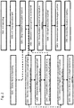
- Figure 2 shows a flowchart illustrating the disclosed method. The method illustrated by Figure 2 is for illustrative purposes only, and some of the steps shown in Figure 2 are optional steps. Optional steps are indicated by dashed boxes.
- the ICE 11 is operating and is being used to generate power.
- the power may be directed to the motor generator 21 and used to move the HEV 13, or may be directed to a battery 17 or other energy storage unit for storage.
- the power may also be used to move the HEV 13 directly (without passing through the motor generator 21 and the electric motor 15).
- an instruction to stop the ICE 11 is sent.
- the instruction may be generated automatically by an engine management unit, or may be manually input by a user of the HEV 13.
- the instruction to stop the ICE 11 is received by the controller 1 (as shown in step S201).
- the first condition may also include further requirements, such as determining that the electric motor 15 is operating (see step SI02), in order to be satisfied.
- the electric motor 15 is operating (see step SI02)
- the false brinelling occurs when the ICE 11 is inoperative and the vehicle is in motion, being powered by the electric motor 15. Accordingly, by including a check that the electric motor 15 of the hybrid electric vehicle 13 is operating in the first condition, the accuracy with which the wear of the bearings can be estimated is increased.
- the evaluation unit 3 may be further configured to retrieve, from the memory 5, cumulative durations corresponding to each of the plurality of angular positions (S202).
- the cumulative durations indicate the total time that the crankshaft 9 has spent stopped in each of the angular positions.
- the evaluation unit 3 may then determine which of the plurality of angular positions has the highest cumulative duration and which of the plurality of angular positions has the lowest cumulative duration.
- the memory 5 may indicate (for example) that the crankshaft 9 has spent 114.00 hours in position A, 115.25 hours in position B, 112.32 hours in position C and 110.81 hours in position D.
- the evaluation unit 3 uses the highest and lowest cumulative durations to determine the difference between the highest and lowest cumulative durations, that is, how much longer the crankshaft 9 has spent stopped in the angular position corresponding to the highest cumulative duration than in the angular position corresponding to the lowest cumulative duration (see step S203).
- the evaluation unit 3 may then compare the difference to a first threshold value (S204).
- a suitable first threshold value is 15 minutes (0.25 hours), although other first threshold values may also be used depending on the specific configuration of the system and of the hybrid vehicle. If the difference is greater than the first threshold value, the controller 1 may then instruct the stopping of the crankshaft 9 in the angular position corresponding to the lowest cumulative duration. In this way, the wear on the bearings of the crankshaft 9 can be spread more equally across the plurality of angular positions, minimising the wear on any one angular position and maximising the lifetime of the crankshaft 9 prior to maintenance.
- the rotation of the crankshaft 9 to the desired stop position may be caused by either the electric motor 15 or the ICE 11, and the HEV 13 may be configured such that both options are available.
- the difference is determined as 4.44 hours. Accordingly, if the example threshold of 15 minutes (0.25 hours) is used, then the difference is higher than the threshold.
- the crankshaft 9 can therefore be caused to rotate to the angular position corresponding to the lowest cumulative duration; position D in this example.
- the evaluation unit 3 may be further configured to compare the highest cumulative duration among the plurality of cumulative durations against a second threshold (step S205).
- the second threshold can be based on a predicted operational lifetime without maintenance of the crankshaft 9, which typically would be of the order of several thousands of hours. The specific value used for the second threshold is typically determined based on the configuration of the system. If the highest cumulative duration is found to exceed the second threshold, a maintenance warning can then be output (S206).
- the maintenance warning can be output in any suitable way, for example, a warning light on a dashboard, an audible warning, a display on a screen in the vehicle, a warning logged in the vehicle systems to be passed to an engineer when the HEV 13 is serviced, and so on.
- step S301 the method then continues with step S301. That is, the method may proceed to step S301 immediately following step S201.
- the evaluation unit 3 uses data supplied by the position sensor 7 to determine the angular position in which the crankshaft 9 has stopped. Typically the position sensor 7 will monitor the position of the crankshaft 9 only when the crankshaft 9 has stopped rotating, although the position sensor 7 may also monitor the position of the crankshaft 9 constantly.
- the position sensor 7 is configured to monitor the position of the crankshaft 9 only when the crankshaft 9 has stopped rotating, these measurements may be taken automatically by the sensor 7 and sent to the evaluation unit 3, or alternatively may be taken in response to a query from the evaluation unit.
- the crankshaft 9 is shown stopped in angular position A (example positions A, B, C and D are marked on Figure 1 ). Once the angular position has been determined, this is recorded in the memory (S401).
- the method does not require any further actions (with the potential exception of running a timer starting from the point at which the angular position of the crankshaft 9 is recorded in the memory) until a second condition is satisfied (S501), the second condition comprising that an instruction to start the ICE 11 is received by the controller 1.
- the second condition may also include other requirements.
- the time duration during which the crankshaft 9 remained in the recorded angular position is determined (S601). This determination may use the output of a timer that started at point at which the angular position of the crankshaft 9 is recorded in the memory, or an alternative time determination means such as retrieving time information from a computing or controlling system included in the HEV 13. Once the time duration has been determined, this information is recorded in the memory 5 in conjunction with the recorded angular stop position (S701). Although the information can be recorded in any form, such as a chronological listing of the stop positions linked to the durations, typically this information is recorded by maintaining a cumulative duration that the crankshaft 9 spends in each of the angular positions.
- the time duration determined in step S601 is added to any already recorded duration corresponding to the recorded angular stop position.
- the contents of the memory 5 may be output to the user of the HEV 13, or to an engineer servicing the HEV 13, either periodically, in response to specific queries, or when threshold values are exceeded (for example).
- the present disclosure advantageously provides a controller 1 and method for controlling a crankshaft 9 of an ICE 11 and monitoring the cumulative duration that the crankshaft 9 spends stopped in each of a plurality of angular positions. This allows the wear on the crankshaft 9 bearings to be accurately predicted, and the failure point of the bearings may be estimated and addressed by maintenance if necessary.
- the disclosure also relates to controllers and methods for causing the crankshaft 9 to stop in an angular position having a lowest cumulative duration if desirable, thereby allowing the wear on the bearings of the crankshaft 9 to be spread more equally across the plurality of angular positions, minimising the wear on any one angular position and maximising the lifetime of the crankshaft 9 prior to maintenance.
Landscapes
- Engineering & Computer Science (AREA)
- Mechanical Engineering (AREA)
- Chemical & Material Sciences (AREA)
- Combustion & Propulsion (AREA)
- Transportation (AREA)
- Automation & Control Theory (AREA)
- General Engineering & Computer Science (AREA)
- Human Computer Interaction (AREA)
- Electric Propulsion And Braking For Vehicles (AREA)
- Hybrid Electric Vehicles (AREA)
- Combined Controls Of Internal Combustion Engines (AREA)
Abstract
an evaluation unit;
a memory connected to the evaluation unit and configured to store information relating to a plurality of angular positions of the crankshaft; and
a position sensor connected to the evaluation unit and configured to monitor an angular stop position, from among the plurality of angular positions, of the crankshaft,
wherein, when a first condition is satisfied, the evaluation unit is configured to:
determine the angular position of the crankshaft using data from the position sensor; and
record the angular stop position of the crankshaft in the memory, and
when a second condition is satisfied, the evaluation unit is configured to:
determine the time duration during which the crankshaft remained in the recorded angular stop position; and
record the determined time duration in conjunction with the recorded angular stop position in the memory,
wherein the first condition comprises an instruction to stop the internal combustion engine being received by the controller, and the second condition comprises an instruction to start the internal combustion engine being received by the controller.
Description
- This disclosure relates generally to a controller and control method for a crankshaft, in particular for a crankshaft of a hybrid electric vehicle.
- In recent years, hybrid electric vehicles (HEV) have become increasingly common, and this trend seems likely to continue. Hybrid electric vehicles comprise at least two power units: an electric motor and a further power unit. The further power unit is generally an internal combustion engine (ICE) and typically a petrol engine, although diesel engines, liquid petroleum gas engines or other engines may also be used. The exact means by which the power allowing the vehicle to move is supplied varies depending on the specific vehicle configuration, but all available power units are generally involved. An example of a common power scheme is one in which the electric motor is used to satisfy power requirements up to a given level, and then the further power unit (for example, ICE) is used in conjunction with the electric motor to provide power above the given level. Alternatively, the further power unit may operate even when the power output from this further power unit is not required to move the vehicle, with the power output from the further power unit instead being used to charge one or more batteries, which the electric motor can draw on. Alternative power supply schemes, which may incorporate one or both of the schemes discussed above, can also be used.
- As mentioned in the passage above, electric motors in hybrid electric vehicles typically draw on batteries as energy reserves, draining the batteries as they provide motive power for the vehicle. Other energy storage means, such as capacitors or flywheels, may also be used, although battery storage is the most commonly used energy storage means. One example of a mechanism by which the battery may be charged is discussed above, whereby a further engine of the hybrid electric vehicle is used to charge the battery. The battery may also be charged by further vehicle systems, such as regenerative braking systems which store energy recovered during braking in the battery. In addition to (or alternatively to) the battery charging systems discussed above, an external power source may also be used to charge the battery. The hybrid electric vehicle may be connected to a power source such as a large external battery or generator or a mains electric connection via a power cable or other power supply connection (such as inductive charging). The power source can be used to charge the battery, typically while the HEV is stationary (for example, if the HEV is a personal car, while the HEV is parked overnight), and then the battery charge can subsequently be used to provide motive power. Use of external charging means can allow the battery to be fully charged faster than vehicle based systems. Further, by using a combination of external power sources and vehicle based systems, the distance the vehicle is able to travel between refuelling/recharging stops can be increased. As such, vehicles that allow the use of both external power sources and vehicle based systems can be referred to as Range Extender Vehicles (REVs) or Plug In Hybrid Electric Vehicles (PHEVs).
- Generally, REVs and PHEVs are configured to draw stored energy from batteries as much as possible, without engaging the further power unit (for example, ICE). This mode of operation is usually more cost efficient than modes which utilise the further power unit to a greater extent, because a unit of energy obtained from an external power source (such as a mains electricity connection) will typically be a fraction of the cost of an equivalent unit of energy obtained in the form of petrol, LPG, diesel, and so on. As a result of this mode of operation, it is common for an ICE to be inactive for a comparatively large portion of the hybrid electric vehicle lifetime, even during periods while the hybrid electric vehicle is in motion.
- When an ICE is deactivated, the crankshaft of the ICE will typically stop in one of a limited number of discrete angular positions. For example, where a full rotation of the crankshaft with respect to the remainder of the ICE encompasses the rotation of a given point on the circumference of the crankshaft through 360° about the rotational axis of the crankshaft, the crankshaft may naturally stop with the given point rotated through 90°, 180°, 270° or 360°. The crankshaft is caused to stop at a limited number of angular positions due to the engine geometry, with factors such as the number and arrangement of the cylinders determining the discrete positions. Of course, the use of four discrete angular positions listed above (90°, 180°, 270° and 360°) is simply an example, and other numbers and spacings (including uneven spacings) of discrete angular positions will be engendered by other ICE configurations.
- In a traditional vehicle powered exclusively by the ICE, the limited number of crankshaft angular stopping positions would not be a major concern; the ICE would, by necessity, be operational while the vehicle was in operation and therefore the crankshaft would be rotating. However, in hybrid electric vehicles, and particularly in REVs/PHEVs, the ICE will commonly be inactive while the vehicle is in operation. While the ICE is inactive and the vehicle is in operation, the motion of the vehicle (particularly vibrations due to road surfaces over which the vehicle travels) can cause the rolling elements in crankshaft bearings to impact into the bearing races. A cumulative result of these impacts is false brinelling, a process whereby the repeated impacts between the rolling elements and the races form wear marks in both the bearings and the races, leading to an uneven wear pattern in the bearing elements and potentially to the premature failure of the bearing.
- It is desirable to monitor the angular position of the crankshaft of an ICE in a HEV over the lifetime of the HEV.
- According to an aspect of the present disclosure, there is provided a controller for a crankshaft of an internal combustion engine, the controller comprising:
- an evaluation unit;
- a memory connected to the evaluation unit and configured to store cumulative durations that the crankshaft has spent in each angular position among a plurality of angular positions; and
- a position sensor connected to the evaluation unit and configured to monitor an angular stop position, from among the plurality of angular positions, of the crankshaft,
- determine the angular position of the crankshaft using data from the position sensor; and
- record the angular stop position of the crankshaft in the memory, and
- determine the time duration during which the crankshaft remained in the recorded angular stop position; and
- record the determined time duration in conjunction with the recorded angular stop position in the memory,
- The internal combustion engine may be part of a hybrid electric vehicle (HEV). The hybrid electric vehicle may further comprise an electric motor. The internal combustion engine may alternatively be part of another type of vehicle or a generator unit, such as a mobile generator. In these alternative applications an electric motor may also be provided, e.g. to rotate the crankshaft.
- By monitoring the cumulative duration that the crankshaft spends stopped in each of the plurality of angular positions, the wear on the crankshaft bearings can be accurately predicted, and the failure point of the bearings can be estimated and addressed by maintenance if necessary. This information can be stored and then used when the HEV is serviced to determine if crankshaft inspection or repair is desirable.
- The controller may be further configured such that,
when the first condition is satisfied the evaluation unit, after determining the angular position of the crankshaft using data from the position sensor: - retrieves from the memory the plurality of cumulative durations corresponding to the plurality of angular positions, respectively;
- determines the difference between the highest cumulative duration among the plurality of cumulative durations and the lowest cumulative duration among the plurality of cumulative durations; and
- if the difference is greater than a first threshold value, instructs the rotation of the crankshaft to stop at the angular position corresponding to the lowest cumulative duration and record the angular position corresponding to the lowest cumulative duration in the memory as the angular stop position of the crankshaft. In this way, the wear on the bearings of the crankshaft can be spread more equally across the plurality of angular positions, minimising the wear on any one angular position and maximising the lifetime of the crankshaft prior to maintenance. An example of a suitable first threshold value is 15 minutes (0.25 hours), although other first threshold values may also be used as desired, primarily determined by the specific configuration of the HEV.
- The controller may be configured to instruct an electric motor (e.g. the electric motor of the HEV) to cause the crankshaft to stop at the angular position corresponding to the lowest cumulative duration, or alternatively may be configured to instruct the internal combustion engine to cause the crankshaft to stop at the angular position corresponding to the lowest cumulative duration. Although either the electric motor or ICE may be used to control the rotation of the crankshaft, depending on the HEV configuration, use of the electric motor may provide an additional advantage of allowing additional angular stop positions than those provided by the ICE to be used, thereby potentially further extending the lifetime of the crankshaft. Some configurations may separately use both the electric motor and the ICE to cause the crankshaft to stop at the desired angular position; this configuration may increase both the complexity and the versatility of the system.
- The controller may be configured such that, when retrieving from the memory the plurality of cumulative durations, the evaluation unit determines if the highest cumulative duration exceeds a second threshold value,
wherein, if the highest cumulative duration exceeds the second threshold value, a maintenance warning is output. The maintenance warning can be used to indicate to the user of the vehicle, or a mechanic, the wear level of the crankshaft bearings. By indicating the wear level, decisions regarding the maintenance of the crankshaft can be made without the requirement to physically inspect the crankshaft. The maintenance warning can be issued at any suitable point, for example at the end of the service life of the crankshaft. - The number of angular positions used in the system is determined by the system properties, such as the size ratio between the rolling elements and the races of the bearings. The angular positions are generally equally spaced around the circumference of the crankshaft, and are generally spaced sufficiently far apart so as to not overlap one another. As an example, the system may consist of 60 angular positions, arranged at intervals of 6° about the crankshaft circumference.
- In addition to an instruction to stop the internal combustion engine being received by the controller, the first condition may further comprise determining that the electric motor of the hybrid electric vehicle is operating and/or that the HEV is moving. Although some wear may occur to the bearing while the vehicle is stationary (and neither of the electric motor or ICE is operating), false brinelling would typically occur when the ICE is inoperative and the vehicle is in motion, being powered by the electric motor. Accordingly, by including a check that the electric motor of the hybrid electric vehicle is operating in the first condition, the accuracy with which the wear of the bearings can be estimated is increased.
- The position sensor may be a bi-directional crankshaft position sensor installed on the internal combustion engine, or alternatively may be a resolver or an angular position sensor installed on an electric motor associated with the ICE (e.g. the electric motor of the HEV). The choice of whether to use a position sensor located on the ICE or the electric motor can be made taking into account other properties of the system, such as the proximity of the evaluation unit to the ICE and electric motor respectively or existing sensors which may be included on one or both of the ICE and electric motor for other purposes.
- A vehicle, such as a hybrid electric vehicle, may comprise the controller as discussed above, and may further comprise an electric motor and an internal combustion engine, the internal combustion engine comprising a crankshaft. As discussed above, the system is particularly effective where the ICE is used sparingly during the operation of the vehicle, that is, when the vehicle is primarily powered by the electric motor. Therefore, the system is even more effective where the vehicle comprises a battery unit. The battery unit may be charged using an external electric connection to an external power source in addition to being charged by the internal combustion engine output, and the operational time of the ICE is a low fraction of the operational time of the HEV.
- According to a further aspect of the present disclosure, there is provided a method for controlling a crankshaft of an internal combustion engine, such as in a hybrid electric vehicle, using a controller, the method comprising:
- when a first condition is satisfied:
- determining an angular position of the crankshaft, from among the plurality of angular positions, using data from a position sensor; and
- recording the angular stop position of the crankshaft in a memory, and
- when a second condition is satisfied:
- determining the time duration during which the crankshaft remained in the recorded angular stop position; and
- recording the determined time duration in conjunction with the recorded angular stop position in the memory,
- storing in a memory cumulative durations that the crankshaft has spent in each angular position among the plurality of angular positions, and
- when the first condition is satisfied:
- retrieving from the memory the plurality of cumulative durations corresponding to the plurality of angular positions, respectively;
- determining the difference between the highest cumulative duration among the plurality of cumulative durations and the lowest cumulative duration among the plurality of cumulative durations; and
- if the difference is greater than a first threshold value, stopping the crankshaft at the angular position corresponding to the lowest cumulative duration and recording the angular position corresponding to the lowest cumulative duration in the memory as the angular stop position of the crankshaft. The advantages provided by the method are as discussed above in the context of the controller.
- To avoid unnecessary duplication of effort and repetition of text in the specification, certain features are described in relation to only one or several aspects or embodiments of the invention. However, it is to be understood that, where it is technically possible, features described in relation to any aspect or embodiment of the invention may also be used with any other aspect or embodiment of the invention.
- The invention is described, by way of example only, with reference to the figures, in which:
-
Figure 1 is a schematic diagram of a hybrid electric vehicle including a controller and an internal combustion engine. -
Figure 2 is a flowchart illustrating a method for controlling a crankshaft. - A
controller 1 in accordance with the present disclosure is shown inFigure 1 . Thecontroller 1 comprises anevaluation unit 3, amemory 5 and asensor 7. The controller 1 (or theevaluation unit 3 andmemory 5 of the controller 1) may be integrated into a larger engine management system. Alternatively, thecontroller 1 may be a separate unit. In order to illustrate a relationship between thesensor 7 of thecontroller 1 and acrankshaft 9 of an internal combustion engine (ICE) 11, these components of a hybrid electric vehicle (HEV) 13 are also shown schematically inFigure 1 . Although the ICE 11 may be part of theHEV 13, it is also envisaged that the ICE 11 may alternatively be part of another type of vehicle (such as a motor vehicle) or a generator unit (such as a mobile generator). In these alternative applications an electric motor may also be provided, e.g. to rotate thecrankshaft 9. - In
Figure 1 , the direction of rotation of thecrankshaft 9 of this example system is shown using curved arrows. Four angular positions spaced around the circumference of thecrankshaft 9 are also marked inFigure 1 , using the reference signs A, B, C and D. The angular positions may be defined with respect to, for example, the remainder of the ICE 11. InFigure 1 , thecrankshaft 9 has stopped in position A.Figure 1 shows four angular positions for simplicity; typically the plurality of stop positions of thecrankshaft 9 would consist of a larger number of angular positions, for example, 60 angular positions. - The
HEV 13 inFigure 1 also includes abattery 17, which can be charged by the ICE 11 (via a motor generator 21) or using an external power source (such as an external battery, renewable power source or connection to mains electricity) via an externalelectric connection 19. As discussed above, the system is even more effective where the hybrid vehicle comprises one ormore batteries 17, which may be charged using an externalelectric connection 19 to an external power source in addition to being charged by the internal combustion engine output, because the operational time of the ICE 11 in such systems is often a low fraction of the operational time of theHEV 13. - In the schematic of
Figure 1 , for simplicity only some of the potential connections between components have been illustrated. As an example of this, the potential connection between theelectric motor 15 and thecrankshaft 9 allowing theelectric motor 15 to be used to adjust the angular position of thecrankshaft 9 if desired, has not been shown. The omission of some potential connections does not imply that these connections are any more or less important than the displayed connections; the connections have been omitted simply to improve the clarity of the diagram. -
Figure 2 shows a flowchart illustrating the disclosed method. The method illustrated byFigure 2 is for illustrative purposes only, and some of the steps shown inFigure 2 are optional steps. Optional steps are indicated by dashed boxes. - At the start of the method illustrated in
Figure 2 , the ICE 11 is operating and is being used to generate power. The power may be directed to themotor generator 21 and used to move theHEV 13, or may be directed to abattery 17 or other energy storage unit for storage. The power may also be used to move theHEV 13 directly (without passing through themotor generator 21 and the electric motor 15). In step S101, an instruction to stop the ICE 11 is sent. The instruction may be generated automatically by an engine management unit, or may be manually input by a user of theHEV 13. - The instruction to stop the ICE 11 is received by the controller 1 (as shown in step S201). The first condition may also include further requirements, such as determining that the
electric motor 15 is operating (see step SI02), in order to be satisfied. As explained above, although some wear may occur to the bearing while the vehicle is stationary (and neither of theelectric motor 15 or ICE 11 is operating), the false brinelling occurs when the ICE 11 is inoperative and the vehicle is in motion, being powered by theelectric motor 15. Accordingly, by including a check that theelectric motor 15 of the hybridelectric vehicle 13 is operating in the first condition, the accuracy with which the wear of the bearings can be estimated is increased. - The
evaluation unit 3 may be further configured to retrieve, from thememory 5, cumulative durations corresponding to each of the plurality of angular positions (S202). The cumulative durations indicate the total time that thecrankshaft 9 has spent stopped in each of the angular positions. Where the first condition requires that theelectric motor 15 is operating, the cumulative durations indicate the total time that thecrankshaft 9 has spent stopped in each of the angular positions while theelectric motor 15 is operating. If the cumulative durations have been retrieved, theevaluation unit 3 may then determine which of the plurality of angular positions has the highest cumulative duration and which of the plurality of angular positions has the lowest cumulative duration. With reference to theFigure 1 , thememory 5 may indicate (for example) that thecrankshaft 9 has spent 114.00 hours in position A, 115.25 hours in position B, 112.32 hours in position C and 110.81 hours in position D. - Using the highest and lowest cumulative durations, the
evaluation unit 3 then determines the difference between the highest and lowest cumulative durations, that is, how much longer thecrankshaft 9 has spent stopped in the angular position corresponding to the highest cumulative duration than in the angular position corresponding to the lowest cumulative duration (see step S203). Turning again to the example discussed above, theevaluation unit 3 could then determine that the highest cumulative duration of 115.25 hours corresponded to angular position B, and the lowest cumulative duration of 110.81 hours corresponded to angular position D. Accordingly, the difference could be determined as 115.25 - 110.81 = 4.44 hours. - If the difference between the highest and lowest cumulative durations has been obtained, the
evaluation unit 3 may then compare the difference to a first threshold value (S204). An example of a suitable first threshold value is 15 minutes (0.25 hours), although other first threshold values may also be used depending on the specific configuration of the system and of the hybrid vehicle. If the difference is greater than the first threshold value, thecontroller 1 may then instruct the stopping of thecrankshaft 9 in the angular position corresponding to the lowest cumulative duration. In this way, the wear on the bearings of thecrankshaft 9 can be spread more equally across the plurality of angular positions, minimising the wear on any one angular position and maximising the lifetime of thecrankshaft 9 prior to maintenance. Based on the specific configuration of theHEV 13, the rotation of thecrankshaft 9 to the desired stop position may be caused by either theelectric motor 15 or the ICE 11, and theHEV 13 may be configured such that both options are available. In the example situation, the difference is determined as 4.44 hours. Accordingly, if the example threshold of 15 minutes (0.25 hours) is used, then the difference is higher than the threshold. Thecrankshaft 9 can therefore be caused to rotate to the angular position corresponding to the lowest cumulative duration; position D in this example. - If the cumulative durations corresponding to each of the plurality of angular positions have been retrieved (step S202 has been performed), the
evaluation unit 3 may be further configured to compare the highest cumulative duration among the plurality of cumulative durations against a second threshold (step S205). The second threshold can be based on a predicted operational lifetime without maintenance of thecrankshaft 9, which typically would be of the order of several thousands of hours. The specific value used for the second threshold is typically determined based on the configuration of the system. If the highest cumulative duration is found to exceed the second threshold, a maintenance warning can then be output (S206). The maintenance warning can be output in any suitable way, for example, a warning light on a dashboard, an audible warning, a display on a screen in the vehicle, a warning logged in the vehicle systems to be passed to an engineer when theHEV 13 is serviced, and so on. - In addition to or alternatively to comparing the highest of the cumulative durations against the second threshold, further comparisons and determinations may be made using the cumulative duration values (in conjunction with the corresponding angular position values). In an example of a further comparison, a total cumulative duration may be obtained by calculating a sum of the plurality of cumulative durations corresponding to the plurality of angular positions. The total cumulative duration therefore indicates the total stationary time of the
crankshaft 9 in all of the angular positions (which, as discussed above, may be the total time while the HEV is moving). This total cumulative duration can then be compared against a threshold value and, if the total cumulative duration exceeds the threshold value, a warning can then be output as discussed above. In the example discussed above, the total cumulative duration could be obtained by adding the cumulative durations for angular positions A to D, thereby obtaining a total cumulative duration of 114.00 + 115.25 + 112.32 + 110.81 = 452.38 hours. - Regardless of whether or not the cumulative duration comparison and rotation process of steps S202 to S204, or the second threshold comparison process of steps S205 and S206, have been performed, the method then continues with step S301. That is, the method may proceed to step S301 immediately following step S201. In step S301, the
evaluation unit 3 then uses data supplied by theposition sensor 7 to determine the angular position in which thecrankshaft 9 has stopped. Typically theposition sensor 7 will monitor the position of thecrankshaft 9 only when thecrankshaft 9 has stopped rotating, although theposition sensor 7 may also monitor the position of thecrankshaft 9 constantly. Where theposition sensor 7 is configured to monitor the position of thecrankshaft 9 only when thecrankshaft 9 has stopped rotating, these measurements may be taken automatically by thesensor 7 and sent to theevaluation unit 3, or alternatively may be taken in response to a query from the evaluation unit. In the example shown inFigure 1 , thecrankshaft 9 is shown stopped in angular position A (example positions A, B, C and D are marked onFigure 1 ). Once the angular position has been determined, this is recorded in the memory (S401). - The method does not require any further actions (with the potential exception of running a timer starting from the point at which the angular position of the
crankshaft 9 is recorded in the memory) until a second condition is satisfied (S501), the second condition comprising that an instruction to start the ICE 11 is received by thecontroller 1. The second condition may also include other requirements. - When the second condition is satisfied, the time duration during which the
crankshaft 9 remained in the recorded angular position is determined (S601). This determination may use the output of a timer that started at point at which the angular position of thecrankshaft 9 is recorded in the memory, or an alternative time determination means such as retrieving time information from a computing or controlling system included in theHEV 13. Once the time duration has been determined, this information is recorded in thememory 5 in conjunction with the recorded angular stop position (S701). Although the information can be recorded in any form, such as a chronological listing of the stop positions linked to the durations, typically this information is recorded by maintaining a cumulative duration that thecrankshaft 9 spends in each of the angular positions. Where cumulative durations are maintained for each angular position, the time duration determined in step S601 is added to any already recorded duration corresponding to the recorded angular stop position. The contents of thememory 5 may be output to the user of theHEV 13, or to an engineer servicing theHEV 13, either periodically, in response to specific queries, or when threshold values are exceeded (for example). - The present disclosure advantageously provides a
controller 1 and method for controlling acrankshaft 9 of an ICE 11 and monitoring the cumulative duration that thecrankshaft 9 spends stopped in each of a plurality of angular positions. This allows the wear on thecrankshaft 9 bearings to be accurately predicted, and the failure point of the bearings may be estimated and addressed by maintenance if necessary. The disclosure also relates to controllers and methods for causing thecrankshaft 9 to stop in an angular position having a lowest cumulative duration if desirable, thereby allowing the wear on the bearings of thecrankshaft 9 to be spread more equally across the plurality of angular positions, minimising the wear on any one angular position and maximising the lifetime of thecrankshaft 9 prior to maintenance. - It will be appreciated by those skilled in the art that although the invention has been described by way of example, with reference to one or more examples, it is not limited to the disclosed examples and alternative examples may be constructed without departing from the scope of the invention as defined by the appended claims.
Claims (15)
- A controller for a crankshaft of an internal combustion engine, the controller comprising:an evaluation unit;a memory connected to the evaluation unit and configured to store cumulative durations that the crankshaft has spent in each angular position among a plurality of angular positions; anda position sensor connected to the evaluation unit and configured to monitor an angular stop position, from among the plurality of angular positions, of the crankshaft,wherein, when a first condition is satisfied, the evaluation unit is configured to:determine the angular position of the crankshaft using data from the position sensor; andrecord the angular stop position of the crankshaft in the memory, andwhen a second condition is satisfied, the evaluation unit is configured to:determine the time duration during which the crankshaft remained in the recorded angular stop position; andrecord the determined time duration in conjunction with the recorded angular stop position in the memory,wherein the first condition comprises an instruction to stop the internal combustion engine being received by the controller, and the second condition comprises an instruction to start the internal combustion engine being received by the controller.
- The controller of claim 1, wherein:when the first condition is satisfied the evaluation unit is further configured, after determining the angular position of the crankshaft using data from the position sensor, to:retrieve from the memory the plurality of cumulative durations corresponding to the plurality of angular positions, respectively;determine the difference between the highest cumulative duration among the plurality of cumulative durations and the lowest cumulative duration among the plurality of cumulative durations; andif the difference is greater than a first threshold value, instruct the rotation of the crankshaft to stop at the angular position corresponding to the lowest cumulative duration and record the angular position corresponding to the lowest cumulative duration in the memory as the angular stop position of the crankshaft.
- The controller of claim 2, wherein the first threshold value is 15 minutes.
- The controller of claim 2 or 3, configured to instruct an electric motor to cause the crankshaft to stop at the angular position corresponding to the lowest cumulative duration.
- The controller of any of claims 2 to 4, configured to instruct the internal combustion engine to cause the crankshaft to stop at the angular position corresponding to the lowest cumulative duration.
- The controller of any of claims 2 to 5 wherein, when retrieving from the memory the plurality of cumulative durations, the evaluation unit is further configured to determine if the highest cumulative duration exceeds a second threshold value,
wherein, if the highest cumulative duration exceeds the second threshold value, a maintenance warning is output. - The controller of any of claims 1 to 6, wherein the plurality of angular positions consists of 60 angular positions, arranged at intervals of 6° about the crankshaft circumference.
- The controller of any of claims 1 to 7, wherein the position sensor is a bi-directional crankshaft position sensor installed on the internal combustion engine.
- The controller of any of claims 1 to 8, wherein the position sensor is a resolver or an angular position sensor installed on an electric motor associated with the internal combustion engine.
- The controller of any of claims 1 to 9, wherein the internal combustion engine is part of a hybrid electric vehicle, the hybrid electric vehicle further comprising an electric motor.
- The controller of claim 10, wherein the first condition further comprises determining that the electric motor of the hybrid electric vehicle is operating.
- A vehicle comprising the controller of any of claims 1 to 11, further comprising an electric motor and an internal combustion engine, the internal combustion engine comprising a crankshaft.
- The vehicle of claim 12, further comprising a battery unit, wherein the battery unit is configured to allow charging from the internal combustion engine output and from an external electric connection.
- A method for controlling a crankshaft of an internal combustion engine using a controller, the method comprising:when a first condition is satisfied:determining an angular position of the crankshaft, from among the plurality of angular positions, using data from a position sensor; andrecording the angular stop position of the crankshaft in a memory, andwhen a second condition is satisfied:wherein the first condition comprises an instruction to stop the internal combustion engine being received by the controller, and the second condition comprises an instruction to start the internal combustion engine being received by the controller.determining the time duration during which the crankshaft remained in the recorded angular stop position; andrecording the determined time duration in conjunction with the recorded angular stop position in the memory,
- The method of claim 14, further comprising:storing in a memory cumulative durations that the crankshaft has spent in each angular position among the plurality of angular positions, andwhen the first condition is satisfied:retrieving from the memory the plurality of cumulative durations corresponding to the plurality of angular positions, respectively;determining the difference between the highest cumulative duration among the plurality of cumulative durations and the lowest cumulative duration among the plurality of cumulative durations; andif the difference is greater than a first threshold value, stopping the crankshaft at the angular position corresponding to the lowest cumulative duration and recording the angular position corresponding to the lowest cumulative duration in the memory as the angular stop position of the crankshaft.
Applications Claiming Priority (1)
| Application Number | Priority Date | Filing Date | Title |
|---|---|---|---|
| GB1801834.1A GB2570709B (en) | 2018-02-05 | 2018-02-05 | Controller for a crankshaft of an internal combustion engine in a hybrid vehicle |
Publications (2)
| Publication Number | Publication Date |
|---|---|
| EP3527446A1 true EP3527446A1 (en) | 2019-08-21 |
| EP3527446B1 EP3527446B1 (en) | 2020-07-15 |
Family
ID=61731004
Family Applications (1)
| Application Number | Title | Priority Date | Filing Date |
|---|---|---|---|
| EP19152195.4A Active EP3527446B1 (en) | 2018-02-05 | 2019-01-16 | Crankshaft controller |
Country Status (4)
| Country | Link |
|---|---|
| US (1) | US10738725B2 (en) |
| EP (1) | EP3527446B1 (en) |
| CN (1) | CN110116733A (en) |
| GB (1) | GB2570709B (en) |
Families Citing this family (2)
| Publication number | Priority date | Publication date | Assignee | Title |
|---|---|---|---|---|
| US10900458B2 (en) * | 2019-05-08 | 2021-01-26 | GM Global Technology Operations LLC | Apparatus and method for control of powertrain stop position |
| CN116161039B (en) * | 2023-03-27 | 2025-12-05 | 东风汽车集团股份有限公司 | Methods and systems for preventing wear on bearings of series-parallel hybrid vehicle engines |
Citations (3)
| Publication number | Priority date | Publication date | Assignee | Title |
|---|---|---|---|---|
| US20020093202A1 (en) * | 2001-01-16 | 2002-07-18 | Downs Robert Charles | Crankshaft rotation control in a hybrid electric vehicle |
| EP2738058A1 (en) * | 2011-07-28 | 2014-06-04 | Toyota Jidosha Kabushiki Kaisha | Engine stop control device for hybrid vehicle |
| JP2015033963A (en) * | 2013-08-09 | 2015-02-19 | いすゞ自動車株式会社 | Hybrid system, hybrid vehicle and power transmission method for hybrid system |
Family Cites Families (21)
| Publication number | Priority date | Publication date | Assignee | Title |
|---|---|---|---|---|
| JP3770235B2 (en) * | 2003-01-28 | 2006-04-26 | トヨタ自動車株式会社 | Internal combustion engine stop position estimation device |
| DE102004049578A1 (en) * | 2004-10-12 | 2006-04-13 | Robert Bosch Gmbh | Starting method for internal combustion engine involves regulating direction and angle of rotation of crankshaft based on signal levels stored in non-volatile memory |
| JP4506527B2 (en) * | 2005-03-18 | 2010-07-21 | トヨタ自動車株式会社 | Control device for internal combustion engine |
| DE102009036444A1 (en) | 2009-08-06 | 2011-02-10 | Daimler Ag | Driving arrangement for e.g. electric vehicle, has range extender non-contributory operated for moving along vehicle and connected with hybrid-refrigerant compressor and scroll compressors for driving compressors |
| US8226525B2 (en) * | 2009-09-01 | 2012-07-24 | GM Global Technology Operations LLC | Engine starting control apparatus and method for a hybrid vehicle |
| KR101047636B1 (en) * | 2009-09-16 | 2011-07-07 | 기아자동차주식회사 | System and method for reducing engine start time |
| JP2012035781A (en) * | 2010-08-09 | 2012-02-23 | Toyota Motor Corp | Control device of hybrid vehicle |
| AT510834B1 (en) | 2010-11-25 | 2012-09-15 | Avl List Gmbh | POWER GENERATION DEVICE, IN PARTICULAR RANGE EXTENDER FOR A MOTOR VEHICLE |
| CN202264650U (en) | 2011-10-27 | 2012-06-06 | 韩群山 | Connection structure of fuel oil engine and generator of extended range electric vehicle |
| JP5849810B2 (en) * | 2012-03-23 | 2016-02-03 | トヨタ自動車株式会社 | Control device for internal combustion engine |
| JP5737261B2 (en) * | 2012-10-16 | 2015-06-17 | トヨタ自動車株式会社 | vehicle |
| CN104781524B (en) * | 2012-10-26 | 2018-09-28 | 三菱电机株式会社 | Being automatically stopped of internal combustion engine/rebooting device and internal combustion engine are automatically stopped/method for restarting |
| JP6002049B2 (en) * | 2013-01-16 | 2016-10-05 | 本田技研工業株式会社 | Control device for active anti-vibration support device |
| JP6071568B2 (en) * | 2013-01-16 | 2017-02-01 | 本田技研工業株式会社 | Vehicle control device |
| DE102013204488A1 (en) | 2013-03-14 | 2014-09-18 | Robert Bosch Gmbh | A method and apparatus for avoiding damage to a bearing of at least one shaft of a range extender of an electric vehicle |
| JP6070669B2 (en) * | 2014-10-02 | 2017-02-01 | トヨタ自動車株式会社 | Engine stop device |
| JP6435767B2 (en) * | 2014-10-17 | 2018-12-12 | いすゞ自動車株式会社 | Diesel engine stop device |
| JP2016217231A (en) | 2015-05-19 | 2016-12-22 | トヨタ自動車株式会社 | Regenerative power absorber using gas turbine range extender |
| US10295026B2 (en) | 2015-07-08 | 2019-05-21 | Agco Corporation | Belt drive system |
| CN105909378B (en) | 2016-06-03 | 2018-03-30 | 韩群山 | The mixed generator of extended-range electricity and engine crankshaft coupling arrangement |
| KR102463459B1 (en) * | 2017-12-27 | 2022-11-04 | 현대자동차주식회사 | Method for Improving Engine Start Performance of Vehicle |
-
2018
- 2018-02-05 GB GB1801834.1A patent/GB2570709B/en active Active
-
2019
- 2019-01-16 EP EP19152195.4A patent/EP3527446B1/en active Active
- 2019-01-31 CN CN201910097437.4A patent/CN110116733A/en active Pending
- 2019-01-31 US US16/263,426 patent/US10738725B2/en active Active
Patent Citations (3)
| Publication number | Priority date | Publication date | Assignee | Title |
|---|---|---|---|---|
| US20020093202A1 (en) * | 2001-01-16 | 2002-07-18 | Downs Robert Charles | Crankshaft rotation control in a hybrid electric vehicle |
| EP2738058A1 (en) * | 2011-07-28 | 2014-06-04 | Toyota Jidosha Kabushiki Kaisha | Engine stop control device for hybrid vehicle |
| JP2015033963A (en) * | 2013-08-09 | 2015-02-19 | いすゞ自動車株式会社 | Hybrid system, hybrid vehicle and power transmission method for hybrid system |
Also Published As
| Publication number | Publication date |
|---|---|
| US20190242308A1 (en) | 2019-08-08 |
| GB201801834D0 (en) | 2018-03-21 |
| US10738725B2 (en) | 2020-08-11 |
| GB2570709B (en) | 2020-05-13 |
| CN110116733A (en) | 2019-08-13 |
| GB2570709A (en) | 2019-08-07 |
| EP3527446B1 (en) | 2020-07-15 |
Similar Documents
| Publication | Publication Date | Title |
|---|---|---|
| US8768553B2 (en) | Method and system for controlling charging of battery for hybrid electric vehicle | |
| US6630813B2 (en) | Method and apparatus for monitoring the state of the battery of a hybrid electric vehicle | |
| JP5926182B2 (en) | Hybrid vehicle motor assistance based on user input | |
| JP5998755B2 (en) | Vehicle power supply control apparatus and method | |
| JP4258348B2 (en) | Battery deterioration diagnosis device and on-vehicle power supply control device | |
| JP4333795B2 (en) | Control device for hybrid vehicle | |
| RU2709360C2 (en) | Computing device and method of determining serviceability of storage battery of vehicle | |
| JPH06511134A (en) | drive unit for automobiles | |
| KR101417401B1 (en) | Apparatus for guiding drive-able distance of electric vehicle and method thereof | |
| KR20120072372A (en) | Motor assistance for a hybrid vehicle based on predicted driving range | |
| WO2007091710A1 (en) | Battery life evaluation device for hybrid vehicle | |
| CN107107764B (en) | Method and device for charging an electrical energy storage system in a vehicle | |
| CN105122029A (en) | Method for monitoring state of health of a vehicle system | |
| EA030230B1 (en) | Systems and methods for diagnosing an engine | |
| US9651454B2 (en) | System for checking a combustion engine coupled with an electric generator of a hybrid terrestrial vehicle having a drive line driven by at least one electric motor | |
| WO2005054021A1 (en) | Vehicle breakdown diagnosis system | |
| KR20190017326A (en) | Battery Management apparatus, Vehicle and method for controlling the same | |
| EP3527446B1 (en) | Crankshaft controller | |
| JP5454588B2 (en) | Control device and hybrid vehicle | |
| CN104417542A (en) | Engine oil maintenance monitor for a hybrid electric vehicle | |
| CN109591820A (en) | System and method for fast engine starting | |
| US10553039B2 (en) | System and method for diagnosing deterioration of a drive belt in a vehicle | |
| WO2018110125A1 (en) | Control device | |
| KR20180068463A (en) | Hybrid Vehicle And Method For Start Controlling Of Hybrid Vehicle | |
| US20210253083A1 (en) | Method and System for Evaluating an Operating Condition of a Motor Vehicle |
Legal Events
| Date | Code | Title | Description |
|---|---|---|---|
| PUAI | Public reference made under article 153(3) epc to a published international application that has entered the european phase |
Free format text: ORIGINAL CODE: 0009012 |
|
| STAA | Information on the status of an ep patent application or granted ep patent |
Free format text: STATUS: THE APPLICATION HAS BEEN PUBLISHED |
|
| AK | Designated contracting states |
Kind code of ref document: A1 Designated state(s): AL AT BE BG CH CY CZ DE DK EE ES FI FR GB GR HR HU IE IS IT LI LT LU LV MC MK MT NL NO PL PT RO RS SE SI SK SM TR |
|
| AX | Request for extension of the european patent |
Extension state: BA ME |
|
| STAA | Information on the status of an ep patent application or granted ep patent |
Free format text: STATUS: REQUEST FOR EXAMINATION WAS MADE |
|
| 17P | Request for examination filed |
Effective date: 20191003 |
|
| RBV | Designated contracting states (corrected) |
Designated state(s): AL AT BE BG CH CY CZ DE DK EE ES FI FR GB GR HR HU IE IS IT LI LT LU LV MC MK MT NL NO PL PT RO RS SE SI SK SM TR |
|
| GRAP | Despatch of communication of intention to grant a patent |
Free format text: ORIGINAL CODE: EPIDOSNIGR1 |
|
| STAA | Information on the status of an ep patent application or granted ep patent |
Free format text: STATUS: GRANT OF PATENT IS INTENDED |
|
| RIC1 | Information provided on ipc code assigned before grant |
Ipc: B60W 30/192 20120101ALI20200113BHEP Ipc: B60W 20/00 20160101ALI20200113BHEP Ipc: B60W 30/184 20120101ALI20200113BHEP Ipc: B60W 10/08 20060101ALI20200113BHEP Ipc: B60W 10/06 20060101AFI20200113BHEP |
|
| INTG | Intention to grant announced |
Effective date: 20200207 |
|
| GRAS | Grant fee paid |
Free format text: ORIGINAL CODE: EPIDOSNIGR3 |
|
| GRAA | (expected) grant |
Free format text: ORIGINAL CODE: 0009210 |
|
| STAA | Information on the status of an ep patent application or granted ep patent |
Free format text: STATUS: THE PATENT HAS BEEN GRANTED |
|
| AK | Designated contracting states |
Kind code of ref document: B1 Designated state(s): AL AT BE BG CH CY CZ DE DK EE ES FI FR GB GR HR HU IE IS IT LI LT LU LV MC MK MT NL NO PL PT RO RS SE SI SK SM TR |
|
| REG | Reference to a national code |
Ref country code: CH Ref legal event code: EP Ref country code: GB Ref legal event code: FG4D |
|
| REG | Reference to a national code |
Ref country code: DE Ref legal event code: R096 Ref document number: 602019000254 Country of ref document: DE |
|
| REG | Reference to a national code |
Ref country code: IE Ref legal event code: FG4D |
|
| REG | Reference to a national code |
Ref country code: AT Ref legal event code: REF Ref document number: 1290700 Country of ref document: AT Kind code of ref document: T Effective date: 20200815 |
|
| REG | Reference to a national code |
Ref country code: LT Ref legal event code: MG4D |
|
| REG | Reference to a national code |
Ref country code: AT Ref legal event code: MK05 Ref document number: 1290700 Country of ref document: AT Kind code of ref document: T Effective date: 20200715 |
|
| REG | Reference to a national code |
Ref country code: NL Ref legal event code: MP Effective date: 20200715 |
|
| REG | Reference to a national code |
Ref country code: DE Ref legal event code: R082 Ref document number: 602019000254 Country of ref document: DE Representative=s name: HL KEMPNER PATENTANWAELTE, SOLICITORS (ENGLAND, DE Ref country code: DE Ref legal event code: R082 Ref document number: 602019000254 Country of ref document: DE Representative=s name: HL KEMPNER PATENTANWALT, RECHTSANWALT, SOLICIT, DE Ref country code: DE Ref legal event code: R082 Ref document number: 602019000254 Country of ref document: DE Representative=s name: HL KEMPNER PARTG MBB, DE |
|
| PG25 | Lapsed in a contracting state [announced via postgrant information from national office to epo] |
Ref country code: GR Free format text: LAPSE BECAUSE OF FAILURE TO SUBMIT A TRANSLATION OF THE DESCRIPTION OR TO PAY THE FEE WITHIN THE PRESCRIBED TIME-LIMIT Effective date: 20201016 Ref country code: ES Free format text: LAPSE BECAUSE OF FAILURE TO SUBMIT A TRANSLATION OF THE DESCRIPTION OR TO PAY THE FEE WITHIN THE PRESCRIBED TIME-LIMIT Effective date: 20200715 Ref country code: NO Free format text: LAPSE BECAUSE OF FAILURE TO SUBMIT A TRANSLATION OF THE DESCRIPTION OR TO PAY THE FEE WITHIN THE PRESCRIBED TIME-LIMIT Effective date: 20201015 Ref country code: BG Free format text: LAPSE BECAUSE OF FAILURE TO SUBMIT A TRANSLATION OF THE DESCRIPTION OR TO PAY THE FEE WITHIN THE PRESCRIBED TIME-LIMIT Effective date: 20201015 Ref country code: AT Free format text: LAPSE BECAUSE OF FAILURE TO SUBMIT A TRANSLATION OF THE DESCRIPTION OR TO PAY THE FEE WITHIN THE PRESCRIBED TIME-LIMIT Effective date: 20200715 Ref country code: PT Free format text: LAPSE BECAUSE OF FAILURE TO SUBMIT A TRANSLATION OF THE DESCRIPTION OR TO PAY THE FEE WITHIN THE PRESCRIBED TIME-LIMIT Effective date: 20201116 Ref country code: FI Free format text: LAPSE BECAUSE OF FAILURE TO SUBMIT A TRANSLATION OF THE DESCRIPTION OR TO PAY THE FEE WITHIN THE PRESCRIBED TIME-LIMIT Effective date: 20200715 Ref country code: LT Free format text: LAPSE BECAUSE OF FAILURE TO SUBMIT A TRANSLATION OF THE DESCRIPTION OR TO PAY THE FEE WITHIN THE PRESCRIBED TIME-LIMIT Effective date: 20200715 Ref country code: SE Free format text: LAPSE BECAUSE OF FAILURE TO SUBMIT A TRANSLATION OF THE DESCRIPTION OR TO PAY THE FEE WITHIN THE PRESCRIBED TIME-LIMIT Effective date: 20200715 Ref country code: HR Free format text: LAPSE BECAUSE OF FAILURE TO SUBMIT A TRANSLATION OF THE DESCRIPTION OR TO PAY THE FEE WITHIN THE PRESCRIBED TIME-LIMIT Effective date: 20200715 |
|
| PG25 | Lapsed in a contracting state [announced via postgrant information from national office to epo] |
Ref country code: LV Free format text: LAPSE BECAUSE OF FAILURE TO SUBMIT A TRANSLATION OF THE DESCRIPTION OR TO PAY THE FEE WITHIN THE PRESCRIBED TIME-LIMIT Effective date: 20200715 Ref country code: RS Free format text: LAPSE BECAUSE OF FAILURE TO SUBMIT A TRANSLATION OF THE DESCRIPTION OR TO PAY THE FEE WITHIN THE PRESCRIBED TIME-LIMIT Effective date: 20200715 Ref country code: PL Free format text: LAPSE BECAUSE OF FAILURE TO SUBMIT A TRANSLATION OF THE DESCRIPTION OR TO PAY THE FEE WITHIN THE PRESCRIBED TIME-LIMIT Effective date: 20200715 Ref country code: IS Free format text: LAPSE BECAUSE OF FAILURE TO SUBMIT A TRANSLATION OF THE DESCRIPTION OR TO PAY THE FEE WITHIN THE PRESCRIBED TIME-LIMIT Effective date: 20201115 |
|
| PG25 | Lapsed in a contracting state [announced via postgrant information from national office to epo] |
Ref country code: NL Free format text: LAPSE BECAUSE OF FAILURE TO SUBMIT A TRANSLATION OF THE DESCRIPTION OR TO PAY THE FEE WITHIN THE PRESCRIBED TIME-LIMIT Effective date: 20200715 |
|
| REG | Reference to a national code |
Ref country code: DE Ref legal event code: R097 Ref document number: 602019000254 Country of ref document: DE |
|
| PG25 | Lapsed in a contracting state [announced via postgrant information from national office to epo] |
Ref country code: IT Free format text: LAPSE BECAUSE OF FAILURE TO SUBMIT A TRANSLATION OF THE DESCRIPTION OR TO PAY THE FEE WITHIN THE PRESCRIBED TIME-LIMIT Effective date: 20200715 Ref country code: SM Free format text: LAPSE BECAUSE OF FAILURE TO SUBMIT A TRANSLATION OF THE DESCRIPTION OR TO PAY THE FEE WITHIN THE PRESCRIBED TIME-LIMIT Effective date: 20200715 Ref country code: EE Free format text: LAPSE BECAUSE OF FAILURE TO SUBMIT A TRANSLATION OF THE DESCRIPTION OR TO PAY THE FEE WITHIN THE PRESCRIBED TIME-LIMIT Effective date: 20200715 Ref country code: RO Free format text: LAPSE BECAUSE OF FAILURE TO SUBMIT A TRANSLATION OF THE DESCRIPTION OR TO PAY THE FEE WITHIN THE PRESCRIBED TIME-LIMIT Effective date: 20200715 Ref country code: DK Free format text: LAPSE BECAUSE OF FAILURE TO SUBMIT A TRANSLATION OF THE DESCRIPTION OR TO PAY THE FEE WITHIN THE PRESCRIBED TIME-LIMIT Effective date: 20200715 Ref country code: CZ Free format text: LAPSE BECAUSE OF FAILURE TO SUBMIT A TRANSLATION OF THE DESCRIPTION OR TO PAY THE FEE WITHIN THE PRESCRIBED TIME-LIMIT Effective date: 20200715 |
|
| PLBE | No opposition filed within time limit |
Free format text: ORIGINAL CODE: 0009261 |
|
| STAA | Information on the status of an ep patent application or granted ep patent |
Free format text: STATUS: NO OPPOSITION FILED WITHIN TIME LIMIT |
|
| PG25 | Lapsed in a contracting state [announced via postgrant information from national office to epo] |
Ref country code: AL Free format text: LAPSE BECAUSE OF FAILURE TO SUBMIT A TRANSLATION OF THE DESCRIPTION OR TO PAY THE FEE WITHIN THE PRESCRIBED TIME-LIMIT Effective date: 20200715 |
|
| 26N | No opposition filed |
Effective date: 20210416 |
|
| PG25 | Lapsed in a contracting state [announced via postgrant information from national office to epo] |
Ref country code: SK Free format text: LAPSE BECAUSE OF FAILURE TO SUBMIT A TRANSLATION OF THE DESCRIPTION OR TO PAY THE FEE WITHIN THE PRESCRIBED TIME-LIMIT Effective date: 20200715 |
|
| PG25 | Lapsed in a contracting state [announced via postgrant information from national office to epo] |
Ref country code: SI Free format text: LAPSE BECAUSE OF FAILURE TO SUBMIT A TRANSLATION OF THE DESCRIPTION OR TO PAY THE FEE WITHIN THE PRESCRIBED TIME-LIMIT Effective date: 20200715 Ref country code: MC Free format text: LAPSE BECAUSE OF FAILURE TO SUBMIT A TRANSLATION OF THE DESCRIPTION OR TO PAY THE FEE WITHIN THE PRESCRIBED TIME-LIMIT Effective date: 20200715 |
|
| PG25 | Lapsed in a contracting state [announced via postgrant information from national office to epo] |
Ref country code: LU Free format text: LAPSE BECAUSE OF NON-PAYMENT OF DUE FEES Effective date: 20210116 |
|
| REG | Reference to a national code |
Ref country code: BE Ref legal event code: MM Effective date: 20210131 |
|
| PG25 | Lapsed in a contracting state [announced via postgrant information from national office to epo] |
Ref country code: FR Free format text: LAPSE BECAUSE OF NON-PAYMENT OF DUE FEES Effective date: 20210131 |
|
| PG25 | Lapsed in a contracting state [announced via postgrant information from national office to epo] |
Ref country code: IE Free format text: LAPSE BECAUSE OF NON-PAYMENT OF DUE FEES Effective date: 20210116 |
|
| PG25 | Lapsed in a contracting state [announced via postgrant information from national office to epo] |
Ref country code: BE Free format text: LAPSE BECAUSE OF NON-PAYMENT OF DUE FEES Effective date: 20210131 |
|
| REG | Reference to a national code |
Ref country code: CH Ref legal event code: PL |
|
| PG25 | Lapsed in a contracting state [announced via postgrant information from national office to epo] |
Ref country code: LI Free format text: LAPSE BECAUSE OF NON-PAYMENT OF DUE FEES Effective date: 20220131 Ref country code: CH Free format text: LAPSE BECAUSE OF NON-PAYMENT OF DUE FEES Effective date: 20220131 |
|
| PG25 | Lapsed in a contracting state [announced via postgrant information from national office to epo] |
Ref country code: CY Free format text: LAPSE BECAUSE OF FAILURE TO SUBMIT A TRANSLATION OF THE DESCRIPTION OR TO PAY THE FEE WITHIN THE PRESCRIBED TIME-LIMIT Effective date: 20200715 |
|
| P01 | Opt-out of the competence of the unified patent court (upc) registered |
Effective date: 20230620 |
|
| PG25 | Lapsed in a contracting state [announced via postgrant information from national office to epo] |
Ref country code: HU Free format text: LAPSE BECAUSE OF FAILURE TO SUBMIT A TRANSLATION OF THE DESCRIPTION OR TO PAY THE FEE WITHIN THE PRESCRIBED TIME-LIMIT; INVALID AB INITIO Effective date: 20190116 |
|
| PG25 | Lapsed in a contracting state [announced via postgrant information from national office to epo] |
Ref country code: MK Free format text: LAPSE BECAUSE OF FAILURE TO SUBMIT A TRANSLATION OF THE DESCRIPTION OR TO PAY THE FEE WITHIN THE PRESCRIBED TIME-LIMIT Effective date: 20200715 |
|
| PG25 | Lapsed in a contracting state [announced via postgrant information from national office to epo] |
Ref country code: TR Free format text: LAPSE BECAUSE OF FAILURE TO SUBMIT A TRANSLATION OF THE DESCRIPTION OR TO PAY THE FEE WITHIN THE PRESCRIBED TIME-LIMIT Effective date: 20200715 |
|
| PG25 | Lapsed in a contracting state [announced via postgrant information from national office to epo] |
Ref country code: MT Free format text: LAPSE BECAUSE OF FAILURE TO SUBMIT A TRANSLATION OF THE DESCRIPTION OR TO PAY THE FEE WITHIN THE PRESCRIBED TIME-LIMIT Effective date: 20200715 |
|
| PGFP | Annual fee paid to national office [announced via postgrant information from national office to epo] |
Ref country code: GB Payment date: 20241212 Year of fee payment: 7 |
|
| PGFP | Annual fee paid to national office [announced via postgrant information from national office to epo] |
Ref country code: DE Payment date: 20241217 Year of fee payment: 7 |