EP3527441A1 - Guide-web - Google Patents
Guide-web Download PDFInfo
- Publication number
- EP3527441A1 EP3527441A1 EP19156425.1A EP19156425A EP3527441A1 EP 3527441 A1 EP3527441 A1 EP 3527441A1 EP 19156425 A EP19156425 A EP 19156425A EP 3527441 A1 EP3527441 A1 EP 3527441A1
- Authority
- EP
- European Patent Office
- Prior art keywords
- aperture
- guide plate
- face
- shroud
- webbing guide
- Prior art date
- Legal status (The legal status is an assumption and is not a legal conclusion. Google has not performed a legal analysis and makes no representation as to the accuracy of the status listed.)
- Granted
Links
Images


Classifications
-
- B—PERFORMING OPERATIONS; TRANSPORTING
- B64—AIRCRAFT; AVIATION; COSMONAUTICS
- B64D—EQUIPMENT FOR FITTING IN OR TO AIRCRAFT; FLIGHT SUITS; PARACHUTES; ARRANGEMENT OR MOUNTING OF POWER PLANTS OR PROPULSION TRANSMISSIONS IN AIRCRAFT
- B64D11/00—Passenger or crew accommodation; Flight-deck installations not otherwise provided for
- B64D11/06—Arrangements of seats, or adaptations or details specially adapted for aircraft seats
- B64D11/0691—Arrangements of seats, or adaptations or details specially adapted for aircraft seats specially adapted for cabin crew
-
- B—PERFORMING OPERATIONS; TRANSPORTING
- B60—VEHICLES IN GENERAL
- B60R—VEHICLES, VEHICLE FITTINGS, OR VEHICLE PARTS, NOT OTHERWISE PROVIDED FOR
- B60R22/00—Safety belts or body harnesses in vehicles
- B60R22/18—Anchoring devices
-
- B—PERFORMING OPERATIONS; TRANSPORTING
- B64—AIRCRAFT; AVIATION; COSMONAUTICS
- B64D—EQUIPMENT FOR FITTING IN OR TO AIRCRAFT; FLIGHT SUITS; PARACHUTES; ARRANGEMENT OR MOUNTING OF POWER PLANTS OR PROPULSION TRANSMISSIONS IN AIRCRAFT
- B64D11/00—Passenger or crew accommodation; Flight-deck installations not otherwise provided for
- B64D11/06—Arrangements of seats, or adaptations or details specially adapted for aircraft seats
- B64D11/062—Belts or other passenger restraint means for passenger seats
-
- B—PERFORMING OPERATIONS; TRANSPORTING
- B60—VEHICLES IN GENERAL
- B60R—VEHICLES, VEHICLE FITTINGS, OR VEHICLE PARTS, NOT OTHERWISE PROVIDED FOR
- B60R22/00—Safety belts or body harnesses in vehicles
- B60R22/18—Anchoring devices
- B60R2022/1818—Belt guides
-
- B—PERFORMING OPERATIONS; TRANSPORTING
- B60—VEHICLES IN GENERAL
- B60R—VEHICLES, VEHICLE FITTINGS, OR VEHICLE PARTS, NOT OTHERWISE PROVIDED FOR
- B60R22/00—Safety belts or body harnesses in vehicles
- B60R22/18—Anchoring devices
- B60R2022/1818—Belt guides
- B60R2022/1831—Belt guides comprising a slotted plate sliding in its plane, e.g. inside circular guides
Definitions
- This disclosure relates to safety restraints systems, and more particularly to guiding mechanisms for the restraint webbing, such as those found on a flight attendant seat in an aircraft.
- Safety restraint systems for seats generally comprise a webbing or belt.
- This webbing may pass through one or more guiding mechanisms, which are used to properly orient the webbing.
- the webbing is retracted or extended through these guiding mechanisms.
- the webbing contacts the guiding mechanisms, resulting in the potential for wear with repeated use. The wear may be exacerbated when the webbing binds against the guiding mechanisms.
- the apparatus may comprise a webbing guide plate.
- the webbing guide plate may have an outer face opposite an inner face, a top lateral face, a bottom lateral face, and a first aperture.
- the first aperture may comprise a first arc, displayed across the outer and inner face of the plate. The first aperture may extend from the outer face, through the plate, to the inner face. The first aperture may further comprise a second portion which may extend from the first portion, to the bottom lateral face of the plate.
- first portion of the first aperture may have outward rounded ends.
- the first arc may extend across the outer diameter of the face of the plate.
- second section of the second aperture extends from an outer midpoint of the arc of the first section of the second aperture.
- the plate may further comprise a second raised lip on the outer face of the plate.
- the second lip may trace or outline the first section of the second aperture on the outer face of the plate.
- the first portion of the first aperture may be larger on the inner face of the plate than on the on the outer face of the plate.
- the first portion of the aperture may further comprise a lateral aperture surface.
- the lateral aperture surface may extend from the inner face of the plate to the outer face of the plate.
- the lateral aperture surface may be beveled.
- the guide plate may be curved so that the inner face is convex.
- the system may comprise a webbing guide plate and a shroud.
- the guide plate may comprise an outer face opposite an inner face, a top lateral face, and a bottom lateral face.
- the guide plate may also comprise a first aperture comprising a first arc, which may be displayed across the outer and inner face of the plate. The aperture may extend from the outer face, through the plate, to the inner face.
- the guide plate may further comprise a second aperture comprising a second arc, which may be displayed across the outer and inner face of the plate. The second aperture may extend from the outer face, through the plate, to the inner face.
- the system may further comprise a shroud comprising an inner surface and an outer surface, wherein the inner surface of the shroud may contact the outer face of the webbing guide plate.
- the first aperture of the guide plate may further comprise a second portion, which may extend from the first portion to the bottom lateral face of the plate.
- the first aperture may also comprise two ends that are rounded outward from the midpoint of the first portion of the first aperture.
- the plate may further comprise a first raised lip on the outer face, which may trace the outline of the first portion of the first aperture on the outer face of the plat.
- the plate may also comprise a second raised lip on the outer face which may trace the outline of the first section of the second aperture on the outer face.
- the shroud may comprise a first aperture disposed above the first portion of the first aperture of the guide plate, and a second aperture disposed above the first section of the second aperture of the guide plate.
- the first aperture of the shroud may pass entirely through the shroud from the inner surface to the outer surface.
- the second aperture may pass entirely through the shroud from the inner surface to the outer surface.
- the first raised lip of the guide plate may extend through the first aperture of the shroud.
- the second lip of the guide plate may extend through the second aperture of the shroud.
- the lateral aperture surface of the first part of the first aperture of the plate may be beveled.
- the lateral aperture surface of the first section of the second aperture of the plate may beveled.
- the safety restraint system may comprise a webbing guide plate, which may comprise an outer face opposite an inner face, a bottom lateral face, and a top lateral face.
- the webbing guide plate may further comprise a first webbing guide plate aperture comprising a first arc, displayed across the outer face and the inner face of the webbing guide plate, wherein the first aperture extends from the outer face, through the webbing guide plate, to the inner face; and a second webbing guide plate aperture comprising a second arc, displayed across the outer face and the inner face of the webbing guide plate, wherein the second aperture extends from the outer face, through the webbing guide plate, to the inner face.
- the safety restraint system may further comprise a shroud comprising an inner surface and an outer surface, wherein the inner surface of the shroud contacts the outer face of the webbing guide plate, a first shroud aperture, and a second shroud aperture.
- the safety restraint system may further comprise a restraint webbing that contacts the webbing guide plate.
- the restraint webbing may further comprise a first strap that extends through the first shroud aperture and the first webbing guide plate aperture, and a second strap that extends through the second shroud aperture and the second webbing guide plate aperture.
- any reference to attached, fixed, connected or the like may include permanent, removable, temporary, partial, full and/or any other possible attachment option. Additionally, any reference to without contact (or similar phrases) may also include reduced contact or minimal contact.
- Seat restraints may comprise a four-point or five-point safety restraint or safety harness system.
- a webbing strap extends over each shoulder of the user. These shoulder straps or webbing may retract and extend from the seatback.
- this system may include a guide plate disposed within the seatback 110, behind the shroud 130.
- the restraint webbing 105 may comprise a number of straps or belts.
- a first belt 103 may extend into the seat through a first shroud aperture 131.
- a second belt 102 may extend through a second shroud aperture 132.
- This apparatus may comprise a webbing guide plate 201, which may be referred to herein as a guide plate or plate.
- the guide plate 201 may have a first aperture 210 and a second aperture 220 disposed across an outer face 202 of the guide plate 201.
- the first aperture 210 may comprise a first portion 211 and a second 212 portion
- the second aperture 220 may comprise a first section 221 and a second section 222.
- a first belt 103 of the webbing 105 of a restraint system may be disposed within the first portion 211 of the first aperture 210
- a second belt of the webbing may be disposed within the first section 221 of the second aperture 220.
- the first portion 211 of the first aperture 210 may comprise a first arc 219.
- the first arc 219 may be disposed across the outer face such that the first arc 219 extends laterally across the outer face 202.
- the midpoint 213 of the first arc 219 may be the closest point of the first arc 219 to the top lateral side 230 of the plate.
- the endpoints, 214 and 215, of the first arc 219 may be closer to the top lateral face 240 of the plate than the bottom lateral face 230.
- the radius of the first arc 219 may have a first arc 219 radius of between about 1 inch and about 6 inches (2.54-15.24 centimeters), between about 1.5 inches and about 5 inches (3.81-12.7 centimeters), and between about 2 inches and about 4 inches (5.08-10.16 centimeters), wherein the term "about” in this context only means +/- 0.5 inches (+/- 1.27 centimeters).
- the first section 221 of the second aperture 220 form a second arc 229.
- the second arc 229 may be displayed across the outer face such that the second arc 229 extends in the x direction across the outer face 202.
- the midpoint 223 of the second arc 229 may be the closest point of the second arc 229 to the top lateral side 230 of the plate.
- the endpoints, 224 and 225, of the second arc 229 may be closer to the top lateral face 240 of the plate than the bottom lateral face 230.
- the end points 214 and 215 of the first portion of the first aperture 210 and the end points 224 and 225 of the first section of the second aperture 224 and 225 may be outwardly rounded. This tends to prevent the webbing from catching or binding within a corner. Rather, the webbing may partially fold back over itself.
- the guide plate 201 may be flat, or curved so that the outer face 202 is concave, and the inner face 203 is convex. This curvature may be to accommodate the back of the seat.
- FIG 2B illustrates a cross sectional view off FIG 2A along the A-A line.
- the first aperture 210 may additionally comprise a first lip 216 that surrounds the first portion 211 of the first aperture 210 and extends in the z direction from the outer face 202.
- the second aperture 220 also may additionally comprise a second lip 226 that surrounds the first section 221 of the second aperture 220 and extends in the z direction from the outer face 202.
- the edges 240 of the lip 216 and/or 226 may be curved, rounded or radiused, creating a smooth surface.
- the lips 216 and 226 and the plate 201 are a single piece.
- the lips 216 and 226 may be a bead on the outer face.
- the lips 216 and 226 may extend from the surface of the inner face by between about 0.1 inches to about 0.3 inches (0.254-0.762 centimeters), +/- 0.1 inches (0.254 centimeters).
- the first aperture 210 and second aperture 220 extend entirely through the guide plate 201 from the outer face 202 to the inner face 203.
- the surface area of the first potion 211 of the first aperture 210 and the surface area of the first section 221 of the second aperture 220 on the outer face 202 may be smaller than their respective surface areas on the inner face 203.
- the result is that the inner lateral surface 217 of the first section 211 of the first aperture 210 and the inner lateral surface 227 of the first section 221 of the second aperture 220 are beveled.
- the inner face of the plate may further comprise a recess 270 that extends partially through the plate. The recess may surround the first portion 211 of the first aperture 210 and the first section 221 of the second aperture 220.
- the guide plate 201 [202 is outer face] may also comprise one or more connector apertures 280. These apertures may be used to install the guide plate 201 [202 is outer face] in the seatback.
- the inner face 203 of the guide plate 201 may also comprise one or more bosses 285 that surround one or more connector apertures 280.
- the first aperture 210 and second aperture 220 may each comprise a second portion 212 and second section 222, respectively.
- the second portion 212 may extend from the midpoint of the first portion 213 and the second section 222 may extend from the first section 223 to the bottom lateral face 230 of the guide plate.
- the second portion 212 and the second section 222 may be used to remove or replace the webbing.
- the second portion 212 and the second section 222 may extend parallel to one another from the first portion and the first section, respectively.
- the shroud 301 may have an inner surface 303 and an outer surface 302.
- the outer surface 302 may face away from the seatback.
- the inner surface 303 contacts the outer face of the guide plate.
- the shroud may also be decorative, and it may comprise a different material than the guide plate.
- the shroud may be formed from any suitable material, such as plastic.
- the shroud 301 will have shroud apertures 310 and 320 which correspond to the apertures of the guide plate that the webbing extends through.
- the shroud may comprise a first shroud aperture 310 , and a second shroud aperture 320. Both apertures may extend entirely through the shroud from the inner surface 303 to the outer surface 302.
- the first shroud aperture 310 may have a first portion 311 and a second portion 312.
- the first portion 311 of the first shroud aperture 310 may have the same shape as the first portion of the first aperture in the guide plate.
- the first shroud aperture 310 of the shroud 301 is also aligned with the first aperture of the guide plate.
- the lip surrounding the first portion of the first aperture in the wear plate extends through the first portion 311 of the first shroud aperture 310 so that the webbing will tend not to come into contact with the aperture 310 of the shroud 301 in response to the webbing being extended and retracted.
- the second shroud aperture 320 will have a first section 321 and second section 322.
- the first section 321 of the second shroud aperture 320 has a similar shape to the first section of the second guide plate aperture.
- the second shroud aperture 320 is also aligned with the second aperture of the guide plate so that the lip that surrounds the first section of the second guide plate aperture can extend from the guide plate, and through the first section 321 of the second shroud aperture 320.
- the lip of the first section of the second guide plate aperture will also prevent the webbing from contacting the second shroud aperture 320 when the webbing is extended or allowed to retract through the aperture.
- the webbing With the curvature of the guide plate apertures, the webbing is encouraged to roll over itself rather than bind against the side of the plate, and the lip tends to protect the webbing from the edges of the shroud apertures.
- the first shroud aperture 310 may further comprise a second portion 312 that extends from the first portion 311 of the first aperture 310 out to an edge 340 of the shroud 301.
- the second shroud aperture 320 may further comprise a second section 322 that extends from the first section 321 of the second aperture 320 to an edge 340 of the shroud 301.
- the second portions 312 and second section 322 each may be used to insert or remove the webbing from the shroud.
- the second portion 312 of the first shroud aperture 310 and the second section 322 of the second shroud aperture 320 may be nonadjacent to, or diverge from, the second portions of the first plate aperture and the second plate aperture. In this way the webbing must be manipulated in different directions to install it within the guide plate and within the shroud.
Landscapes
- Engineering & Computer Science (AREA)
- Mechanical Engineering (AREA)
- Aviation & Aerospace Engineering (AREA)
- Automotive Seat Belt Assembly (AREA)
- Professional, Industrial, Or Sporting Protective Garments (AREA)
- Purses, Travelling Bags, Baskets, Or Suitcases (AREA)
Abstract
Description
- This disclosure relates to safety restraints systems, and more particularly to guiding mechanisms for the restraint webbing, such as those found on a flight attendant seat in an aircraft.
- Safety restraint systems for seats generally comprise a webbing or belt. This webbing may pass through one or more guiding mechanisms, which are used to properly orient the webbing. When the restraint system is in use, the webbing is retracted or extended through these guiding mechanisms. The webbing contacts the guiding mechanisms, resulting in the potential for wear with repeated use. The wear may be exacerbated when the webbing binds against the guiding mechanisms.
- Described herein are various embodiments of an apparatus. The apparatus may comprise a webbing guide plate. In various embodiments the webbing guide plate may have an outer face opposite an inner face, a top lateral face, a bottom lateral face, and a first aperture. In various embodiments the first aperture may comprise a first arc, displayed across the outer and inner face of the plate. The first aperture may extend from the outer face, through the plate, to the inner face. The first aperture may further comprise a second portion which may extend from the first portion, to the bottom lateral face of the plate.
- In various embodiments the first portion of the first aperture may have outward rounded ends. The first arc may extend across the outer diameter of the face of the plate. In various embodiments the second section of the second aperture extends from an outer midpoint of the arc of the first section of the second aperture.
- In various embodiments, the plate may further comprise a second raised lip on the outer face of the plate. The second lip may trace or outline the first section of the second aperture on the outer face of the plate.
- In various embodiments, the first portion of the first aperture may be larger on the inner face of the plate than on the on the outer face of the plate. The first portion of the aperture may further comprise a lateral aperture surface. The lateral aperture surface may extend from the inner face of the plate to the outer face of the plate. The lateral aperture surface may be beveled.
- In various embodiments, the guide plate may be curved so that the inner face is convex.
- Also disclosed herein are various embodiments if a system. The system may comprise a webbing guide plate and a shroud. In various embodiments, the guide plate may comprise an outer face opposite an inner face, a top lateral face, and a bottom lateral face. In various embodiments the guide plate may also comprise a first aperture comprising a first arc, which may be displayed across the outer and inner face of the plate. The aperture may extend from the outer face, through the plate, to the inner face. In various embodiments the guide plate may further comprise a second aperture comprising a second arc, which may be displayed across the outer and inner face of the plate. The second aperture may extend from the outer face, through the plate, to the inner face. The system may further comprise a shroud comprising an inner surface and an outer surface, wherein the inner surface of the shroud may contact the outer face of the webbing guide plate.
- In various embodiments, the first aperture of the guide plate may further comprise a second portion, which may extend from the first portion to the bottom lateral face of the plate. The first aperture may also comprise two ends that are rounded outward from the midpoint of the first portion of the first aperture.
- The plate may further comprise a first raised lip on the outer face, which may trace the outline of the first portion of the first aperture on the outer face of the plat. In various embodiments the plate may also comprise a second raised lip on the outer face which may trace the outline of the first section of the second aperture on the outer face.
- In various embodiments the shroud may comprise a first aperture disposed above the first portion of the first aperture of the guide plate, and a second aperture disposed above the first section of the second aperture of the guide plate. The first aperture of the shroud may pass entirely through the shroud from the inner surface to the outer surface. The second aperture may pass entirely through the shroud from the inner surface to the outer surface. The first raised lip of the guide plate may extend through the first aperture of the shroud. The second lip of the guide plate may extend through the second aperture of the shroud. In various embodiments the lateral aperture surface of the first part of the first aperture of the plate may be beveled. In various embodiments the lateral aperture surface of the first section of the second aperture of the plate may be beveled.
- Also found herein are various embodiments of a safety restraint system. In various embodiments the safety restraint system may comprise a webbing guide plate, which may comprise an outer face opposite an inner face, a bottom lateral face, and a top lateral face. The webbing guide plate may further comprise a first webbing guide plate aperture comprising a first arc, displayed across the outer face and the inner face of the webbing guide plate, wherein the first aperture extends from the outer face, through the webbing guide plate, to the inner face; and a second webbing guide plate aperture comprising a second arc, displayed across the outer face and the inner face of the webbing guide plate, wherein the second aperture extends from the outer face, through the webbing guide plate, to the inner face.
- In various embodiments the safety restraint system may further comprise a shroud comprising an inner surface and an outer surface, wherein the inner surface of the shroud contacts the outer face of the webbing guide plate, a first shroud aperture, and a second shroud aperture. In various embodiments the safety restraint system may further comprise a restraint webbing that contacts the webbing guide plate.
- In various embodiments the restraint webbing may further comprise a first strap that extends through the first shroud aperture and the first webbing guide plate aperture, and a second strap that extends through the second shroud aperture and the second webbing guide plate aperture.
- The present disclosure may be better understood with reference to the following drawing figures and description. Non-exhaustive and non-limiting descriptions may refer to the following drawings. The components in the figures are not necessarily to scale as the illustrated principles are emphasized therein. Like numbers in the figures may refer to like parts throughout the different figures unless specified otherwise.
-
FIG. 1 illustrates a portion of the restraint webbing guide system as used on a seat, in accordance with various embodiments; -
FIG. 2A illustrates a view of the outer face of a guide plate, in accordance with various embodiments; -
FIG. 2B illustrates a sectional view along the line A-A inFIG 2A . -
FIG. 2C illustrates a view of the top lateral face of the guide plate, in accordance with various embodiments; -
FIG. 2D illustrates a view of the inner face of the guide plate, in accordance with various embodiments; -
FIG. 2E illustrates a view of the bottom lateral face of the guide plate, in accordance with various embodiments; and -
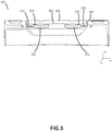
FIG. 3 illustrates a view of the outer surface of a shroud, in accordance with various embodiments. - The detailed description of various embodiments herein refer to the aforementioned drawing figures. These figures and drawings show various embodiments and implementations of the description for purposes of illustration and its best mode, not of limitation. It should be understood that while these embodiments are described in sufficient detail to enable those skilled in the art to practice the embodiments, other embodiments may be realized and that logical and mechanical changes may be made without departing from the scope of the disclosure. Any reference to singular includes plural embodiments. Any reference to more than one component or step may include a singular embodiment or step.
- Also, any reference to attached, fixed, connected or the like may include permanent, removable, temporary, partial, full and/or any other possible attachment option. Additionally, any reference to without contact (or similar phrases) may also include reduced contact or minimal contact. Finally, though the various embodiments discussed herein may be carried out in the context of a seat, and more specifically a seat within an aircraft, it should be understood that systems and methods disclosed herein may be incorporated into any restraint mechanism, particularly those with a webbing, strap, or belt that may be extended or retracted.
- Seat restraints, particularly seat restraints in an airplane, may comprise a four-point or five-point safety restraint or safety harness system. In these systems, a webbing strap extends over each shoulder of the user. These shoulder straps or webbing may retract and extend from the seatback.
- Disclosed herein are various embodiments of a system for webbing guides. With reference to
FIG. 1 , this system may include a guide plate disposed within theseatback 110, behind theshroud 130. Therestraint webbing 105 may comprise a number of straps or belts. Afirst belt 103 may extend into the seat through afirst shroud aperture 131. Asecond belt 102 may extend through asecond shroud aperture 132. - Also described herein are various embodiments of an apparatus. This apparatus may comprise a
webbing guide plate 201, which may be referred to herein as a guide plate or plate. With reference toFIG 2A theguide plate 201 may have afirst aperture 210 and asecond aperture 220 disposed across anouter face 202 of theguide plate 201. Thefirst aperture 210 may comprise afirst portion 211 and a second 212 portion, and thesecond aperture 220 may comprise afirst section 221 and asecond section 222. Afirst belt 103 of thewebbing 105 of a restraint system may be disposed within thefirst portion 211 of thefirst aperture 210, and a second belt of the webbing may be disposed within thefirst section 221 of thesecond aperture 220. - The
first portion 211 of thefirst aperture 210 may comprise afirst arc 219. Thefirst arc 219 may be disposed across the outer face such that thefirst arc 219 extends laterally across theouter face 202. Themidpoint 213 of thefirst arc 219 may be the closest point of thefirst arc 219 to the toplateral side 230 of the plate. The endpoints, 214 and 215, of thefirst arc 219 may be closer to the toplateral face 240 of the plate than the bottomlateral face 230. The radius of thefirst arc 219 may have afirst arc 219 radius of between about 1 inch and about 6 inches (2.54-15.24 centimeters), between about 1.5 inches and about 5 inches (3.81-12.7 centimeters), and between about 2 inches and about 4 inches (5.08-10.16 centimeters), wherein the term "about" in this context only means +/- 0.5 inches (+/- 1.27 centimeters). Additionally, thefirst section 221 of thesecond aperture 220 form asecond arc 229. Thesecond arc 229 may be displayed across the outer face such that thesecond arc 229 extends in the x direction across theouter face 202. Themidpoint 223 of thesecond arc 229 may be the closest point of thesecond arc 229 to the toplateral side 230 of the plate. The endpoints, 224 and 225, of thesecond arc 229 may be closer to the toplateral face 240 of the plate than the bottomlateral face 230. - The end points 214 and 215 of the first portion of the
first aperture 210 and theend points second aperture - The
guide plate 201 may be flat, or curved so that theouter face 202 is concave, and theinner face 203 is convex. This curvature may be to accommodate the back of the seat. -
FIG 2B illustrates a cross sectional view offFIG 2A along the A-A line. With additional reference toFIG 2C , thefirst aperture 210 may additionally comprise afirst lip 216 that surrounds thefirst portion 211 of thefirst aperture 210 and extends in the z direction from theouter face 202. Thesecond aperture 220 also may additionally comprise asecond lip 226 that surrounds thefirst section 221 of thesecond aperture 220 and extends in the z direction from theouter face 202. Theedges 240 of thelip 216 and/or 226 may be curved, rounded or radiused, creating a smooth surface. In various embodiments, thelips plate 201 are a single piece. Thelips lips - With additional reference to
FIG. 2D , thefirst aperture 210 andsecond aperture 220 extend entirely through theguide plate 201 from theouter face 202 to theinner face 203. The surface area of thefirst potion 211 of thefirst aperture 210 and the surface area of thefirst section 221 of thesecond aperture 220 on theouter face 202 may be smaller than their respective surface areas on theinner face 203. The result is that the innerlateral surface 217 of thefirst section 211 of thefirst aperture 210 and the innerlateral surface 227 of thefirst section 221 of thesecond aperture 220 are beveled. The inner face of the plate may further comprise arecess 270 that extends partially through the plate. The recess may surround thefirst portion 211 of thefirst aperture 210 and thefirst section 221 of thesecond aperture 220. - The guide plate 201 [202 is outer face] may also comprise one or
more connector apertures 280. These apertures may be used to install the guide plate 201 [202 is outer face] in the seatback. Theinner face 203 of theguide plate 201 may also comprise one ormore bosses 285 that surround one ormore connector apertures 280. - With additional reference to
FIG 2E , thefirst aperture 210 andsecond aperture 220 may each comprise asecond portion 212 andsecond section 222, respectively. Thesecond portion 212 may extend from the midpoint of thefirst portion 213 and thesecond section 222 may extend from thefirst section 223 to the bottomlateral face 230 of the guide plate. Thesecond portion 212 and thesecond section 222 may be used to remove or replace the webbing. Thesecond portion 212 and thesecond section 222 may extend parallel to one another from the first portion and the first section, respectively. - With reference to
FIG. 3 , theshroud 301 may have aninner surface 303 and anouter surface 302. Theouter surface 302 may face away from the seatback. Theinner surface 303 contacts the outer face of the guide plate. The shroud may also be decorative, and it may comprise a different material than the guide plate. The shroud may be formed from any suitable material, such as plastic. - The
shroud 301 will haveshroud apertures first shroud aperture 310 , and asecond shroud aperture 320. Both apertures may extend entirely through the shroud from theinner surface 303 to theouter surface 302. Thefirst shroud aperture 310 may have afirst portion 311 and asecond portion 312. Thefirst portion 311 of thefirst shroud aperture 310 may have the same shape as the first portion of the first aperture in the guide plate. Thefirst shroud aperture 310 of theshroud 301 is also aligned with the first aperture of the guide plate. The lip surrounding the first portion of the first aperture in the wear plate extends through thefirst portion 311 of thefirst shroud aperture 310 so that the webbing will tend not to come into contact with theaperture 310 of theshroud 301 in response to the webbing being extended and retracted. - Similarly, the
second shroud aperture 320 will have afirst section 321 andsecond section 322. Thefirst section 321 of thesecond shroud aperture 320 has a similar shape to the first section of the second guide plate aperture. Thesecond shroud aperture 320 is also aligned with the second aperture of the guide plate so that the lip that surrounds the first section of the second guide plate aperture can extend from the guide plate, and through thefirst section 321 of thesecond shroud aperture 320. The lip of the first section of the second guide plate aperture will also prevent the webbing from contacting thesecond shroud aperture 320 when the webbing is extended or allowed to retract through the aperture. - With the curvature of the guide plate apertures, the webbing is encouraged to roll over itself rather than bind against the side of the plate, and the lip tends to protect the webbing from the edges of the shroud apertures.
- The
first shroud aperture 310 may further comprise asecond portion 312 that extends from thefirst portion 311 of thefirst aperture 310 out to anedge 340 of theshroud 301. Thesecond shroud aperture 320 may further comprise asecond section 322 that extends from thefirst section 321 of thesecond aperture 320 to anedge 340 of theshroud 301. Thesecond portions 312 andsecond section 322 each may be used to insert or remove the webbing from the shroud. Thesecond portion 312 of thefirst shroud aperture 310 and thesecond section 322 of thesecond shroud aperture 320 may be nonadjacent to, or diverge from, the second portions of the first plate aperture and the second plate aperture. In this way the webbing must be manipulated in different directions to install it within the guide plate and within the shroud. - Additionally, benefits, other advantages, and solutions to problems have been described herein with regard to various embodiments. However, the benefits, advantages, solutions to problems, and any elements that may cause any benefit, advantage, or solution to occur or become more pronounced are not to be construed as critical, required, or essential features or elements of the invention. The scope of the invention is accordingly to be limited by nothing other than the appended claims, in which reference to an element in the singular is not intended to mean "one and only one" unless explicitly so stated, but rather "one or more." Moreover, where a phrase similar to "at least one of A, B, and C" or "at least one of A, B, or C" is used in the claims or specification, it is intended that the phrase be interpreted to mean that A alone may be present in an embodiment, B alone may be present in an embodiment, C alone may be present in an embodiment, or that any combination of the elements A, B and C may be present in a single embodiment; for example, A and B, A and C, B and C, or A and B and C.
- As used herein, the singular forms "a," "an," and "the" include plural referents unless the context clearly dictates otherwise. As used herein, the terms "for example," "for instance," "such as," or "including" are meant to introduce examples that further clarify more general subject matter. Unless otherwise specified, these examples are embodiments of the present disclosure, and are not meant to be limiting in any fashion.
- Furthermore, no element, component, or method step in the present disclosure is intended to be dedicated to the public regardless of whether the element, component, or method step is explicitly recited in the claims. No claim element herein is to be construed under the provisions of 35 U.S.C. 112(f), unless the element is expressly recited using the phrase "means for." As used herein, the terms "comprises", "comprising", or any other variation thereof, are intended to cover a non-exclusive inclusion, such that a process, method, article, or apparatus that comprises a list of elements does not include only those elements but may include other elements not expressly listed or inherent to such process, method, article, or apparatus.
Claims (15)
- An apparatus comprisinga webbing guide plate with an outer face opposite an inner face, anda first aperture having a first portion comprising a first arc that extends through the webbing guide plate from the outer face to the inner face.
- The apparatus of claim 1, wherein the first aperture further comprises a second portion which extends from the first portion, to a bottom lateral face of the webbing guide plate.
- The apparatus of claim 1 or 2, wherein the first portion of the first aperture comprises outward rounded ends.
- The apparatus of claim 2 or 3, wherein the second portion extends from an outer midpoint of the first arc.
- The apparatus of any preceding claim, wherein the webbing guide plate further comprises a first lip on the outer face which traces an outline of the first portion of the first aperture on the outer face, wherein an edge of the first lip is rounded.
- The apparatus of any preceding claim, wherein the webbing guide plate comprises a second aperture extending from the outer face, through the webbing guide plate, to the inner face, wherein the second aperture comprises a first section with outward rounded ends as viewed from the outer side.
- The apparatus of claim 6, wherein the second aperture further comprises a second section which extends from the first section to a bottom lateral face of the plate.
- The apparatus of claim 7, wherein the first aperture further comprises a second portion which extends from the first portion to the bottom lateral face of the plate, parallel to the second section of the second aperture.
- The apparatus of any of claims 6 to 8, wherein the first section of the second aperture comprises an arc, extending across the outer face and the inner face of the plate.
- The apparatus of claim 9, wherein the second section of the second aperture extends from an outer midpoint of the arc of the first section of the second aperture,wherein, optionally, the plate further comprises a second lip on the outer face which traces an outline of the first section of the second aperture on the outer face, wherein an edge of the second lip is rounded,wherein, optionally, the first portion of the first aperture has a greater surface area on the inner face than on the outer face and the first section of the second aperture has a greater surface area on the inner face than on the outer face,wherein, optionally, the first portion of the first aperture comprises a lateral aperture surface extending from an inner face through the plate which is beveled.
- A system comprising:an apparatus as claimed in claim 1, the webbing guide plate further comprisinga bottom lateral face,a top lateral face, anda second aperture having a first section comprising a second arc that extends through the webbing guide plate from the outer face to the inner face; anda shroud comprising an inner surface and an outer face, wherein the inner surface of the shroud contacts the outer face of the webbing guide plate.
- The system of claim 11, wherein the first aperture further comprises a second portion which extends from the first arc, to the bottom lateral face of the webbing guide plate.
- The system of claim 11 or 12, wherein the first portion of the first aperture comprises the first arc and two ends that are rounded outward from a midpoint of the first portion of the first aperture,wherein, optionally, the webbing guide plate further comprises a first raised lip having a rounded edge on the outer face which traces an outline of the first portion of the first aperture on the outer face, and a second raised lip on the outer face which traces the outline of the first section of the second aperture on the outer face,wherein, optionally, the shroud comprisesa first shroud aperture that passes through the shroud from the inner surface to the outer surface, disposed above the first portion of the first aperture of the webbing guide plate, andthe second shroud aperture that passes through the shroud from the inner surface to the outer surface, disposed above the first section of the second aperture of the webbing guide plate, wherein the first raised lip of the webbing guide plate extends through the first shroud aperture, and a second lip of the webbing guide plate extends through the second shroud aperture.
- A safety restraint system comprising:a webbing guide plate, comprising:an outer face opposite an inner face,a first webbing guide plate aperture comprising a first arc, displayed across the outer face and the inner face of the webbing guide plate, wherein a first aperture extends from the outer face, through the webbing guide plate, to the inner face, anda second webbing guide plate aperture comprising a second arc, displayed across the outer face and the inner face of the webbing guide plate, wherein a second aperture extends from the outer face, through the webbing guide plate, to the inner face;a shroud comprising an inner surface and an outer surface, wherein the inner surface of the shroud contacts the outer face of the webbing guide plate, a first shroud aperture, and a second shroud aperture; anda restraint webbing that contacts the webbing guide plate.
- The safety restraint system of claim 14, wherein the restraint webbing further comprises a first strap that extends through the first shroud aperture and the first webbing guide plate aperture, and a second strap that extends through the second shroud aperture and the second webbing guide plate aperture.
Applications Claiming Priority (1)
| Application Number | Priority Date | Filing Date | Title |
|---|---|---|---|
| US15/898,472 US10589865B2 (en) | 2018-02-17 | 2018-02-17 | Guide-web |
Publications (2)
| Publication Number | Publication Date |
|---|---|
| EP3527441A1 true EP3527441A1 (en) | 2019-08-21 |
| EP3527441B1 EP3527441B1 (en) | 2021-04-07 |
Family
ID=65628517
Family Applications (1)
| Application Number | Title | Priority Date | Filing Date |
|---|---|---|---|
| EP19156425.1A Active EP3527441B1 (en) | 2018-02-17 | 2019-02-11 | Guide-web |
Country Status (4)
| Country | Link |
|---|---|
| US (1) | US10589865B2 (en) |
| EP (1) | EP3527441B1 (en) |
| BR (1) | BR102018075832B1 (en) |
| CA (1) | CA3028054A1 (en) |
Families Citing this family (1)
| Publication number | Priority date | Publication date | Assignee | Title |
|---|---|---|---|---|
| US12274237B2 (en) * | 2023-03-29 | 2025-04-15 | Xiamen Sunnypet Products Co., Ltd | Securing mechanism and pet loading accessory using the securing mechanism |
Citations (4)
| Publication number | Priority date | Publication date | Assignee | Title |
|---|---|---|---|---|
| US5716073A (en) * | 1996-07-03 | 1998-02-10 | Chrysler Corporation | Two piece fabric-retaining seat belt bezel |
| FR2861033A1 (en) * | 2003-10-16 | 2005-04-22 | Renault Sa | Seat belt system for motor vehicle, has buckle with support connected to concave retention unit around which webbing is engaged to directly exert traction force on retention unit in usage position |
| WO2015070970A1 (en) * | 2013-11-15 | 2015-05-21 | Trw Automotive Gmbh | Fitting for a seat belt in a vehicle, and seat belt system |
| FR3022873A1 (en) * | 2014-06-30 | 2016-01-01 | Renault Sas | SEAT BELT GUIDE FOR MOTOR VEHICLE |
Family Cites Families (4)
| Publication number | Priority date | Publication date | Assignee | Title |
|---|---|---|---|---|
| US7566075B2 (en) * | 2006-02-06 | 2009-07-28 | Toyota Motor Engineering & Manufacturing North America, Inc. | Seat belt shoulder guide |
| US7510245B2 (en) * | 2006-07-12 | 2009-03-31 | Honda Motor Co., Ltd | Seat belt webbing enclosure |
| US7635167B2 (en) * | 2006-08-30 | 2009-12-22 | Honda Motor Co., Ltd | Seat belt shoulder anchor |
| US9254767B1 (en) * | 2014-09-22 | 2016-02-09 | Sears Manufacturing Co. | Adjustable headrest and seatbelt guide rings |
-
2018
- 2018-02-17 US US15/898,472 patent/US10589865B2/en active Active
- 2018-12-12 BR BR102018075832-2A patent/BR102018075832B1/en active IP Right Grant
- 2018-12-18 CA CA3028054A patent/CA3028054A1/en active Pending
-
2019
- 2019-02-11 EP EP19156425.1A patent/EP3527441B1/en active Active
Patent Citations (4)
| Publication number | Priority date | Publication date | Assignee | Title |
|---|---|---|---|---|
| US5716073A (en) * | 1996-07-03 | 1998-02-10 | Chrysler Corporation | Two piece fabric-retaining seat belt bezel |
| FR2861033A1 (en) * | 2003-10-16 | 2005-04-22 | Renault Sa | Seat belt system for motor vehicle, has buckle with support connected to concave retention unit around which webbing is engaged to directly exert traction force on retention unit in usage position |
| WO2015070970A1 (en) * | 2013-11-15 | 2015-05-21 | Trw Automotive Gmbh | Fitting for a seat belt in a vehicle, and seat belt system |
| FR3022873A1 (en) * | 2014-06-30 | 2016-01-01 | Renault Sas | SEAT BELT GUIDE FOR MOTOR VEHICLE |
Also Published As
| Publication number | Publication date |
|---|---|
| EP3527441B1 (en) | 2021-04-07 |
| BR102018075832B1 (en) | 2022-01-11 |
| US20190256212A1 (en) | 2019-08-22 |
| CA3028054A1 (en) | 2019-08-17 |
| US10589865B2 (en) | 2020-03-17 |
| BR102018075832A2 (en) | 2019-10-08 |
Similar Documents
| Publication | Publication Date | Title |
|---|---|---|
| CN105934365B (en) | Vehicle seat | |
| US5088161A (en) | Seat belt safety clip | |
| US20080054703A1 (en) | Seat belt shoulder anchor | |
| US9988012B2 (en) | Seat belt system | |
| CN109835298B (en) | Seat belt webbing guide | |
| JP4719783B2 (en) | Vehicle seat | |
| CN109969053B (en) | Decorative assembly for vehicle shoulder belt outlet | |
| US9988013B2 (en) | Grip tongue latch plate for seatbelt | |
| US20180281726A1 (en) | Seat belt apparatus | |
| EP3527441A1 (en) | Guide-web | |
| CN111183059B (en) | Seat for vehicle | |
| CN110214100B (en) | Seat belt device for vehicle | |
| US8393645B2 (en) | Devices for adjusting tension in seat belts and other restraint system webs, and associated methods | |
| EP1737710B1 (en) | Shoulder pad for vehicle seat belt | |
| JP6474298B2 (en) | Webbing guide device | |
| CN107963051B (en) | Retaining device for a portion of a belt webbing of a safety belt of a motor vehicle | |
| EP2923895B1 (en) | Belt mounting device | |
| JP2003341472A (en) | Automotive seat belt equipment | |
| US10207609B2 (en) | Vehicle seat back with feature for grasping of seatbelt | |
| US11897417B2 (en) | Safety belt and safety harness separating and fastening system | |
| CN110979252A (en) | Vehicle safety belt device, safety detection method thereof and vehicle | |
| CA2027464C (en) | Seat belt safety clip | |
| US11673493B1 (en) | Children's car seat adapter | |
| JP7352835B2 (en) | Cover member and how to install the cover member | |
| JPH0834313A (en) | Seat belt suspension |
Legal Events
| Date | Code | Title | Description |
|---|---|---|---|
| PUAI | Public reference made under article 153(3) epc to a published international application that has entered the european phase |
Free format text: ORIGINAL CODE: 0009012 |
|
| STAA | Information on the status of an ep patent application or granted ep patent |
Free format text: STATUS: THE APPLICATION HAS BEEN PUBLISHED |
|
| AK | Designated contracting states |
Kind code of ref document: A1 Designated state(s): AL AT BE BG CH CY CZ DE DK EE ES FI FR GB GR HR HU IE IS IT LI LT LU LV MC MK MT NL NO PL PT RO RS SE SI SK SM TR |
|
| AX | Request for extension of the european patent |
Extension state: BA ME |
|
| STAA | Information on the status of an ep patent application or granted ep patent |
Free format text: STATUS: REQUEST FOR EXAMINATION WAS MADE |
|
| 17P | Request for examination filed |
Effective date: 20191119 |
|
| RBV | Designated contracting states (corrected) |
Designated state(s): AL AT BE BG CH CY CZ DE DK EE ES FI FR GB GR HR HU IE IS IT LI LT LU LV MC MK MT NL NO PL PT RO RS SE SI SK SM TR |
|
| GRAP | Despatch of communication of intention to grant a patent |
Free format text: ORIGINAL CODE: EPIDOSNIGR1 |
|
| STAA | Information on the status of an ep patent application or granted ep patent |
Free format text: STATUS: GRANT OF PATENT IS INTENDED |
|
| INTG | Intention to grant announced |
Effective date: 20201021 |
|
| GRAS | Grant fee paid |
Free format text: ORIGINAL CODE: EPIDOSNIGR3 |
|
| GRAA | (expected) grant |
Free format text: ORIGINAL CODE: 0009210 |
|
| STAA | Information on the status of an ep patent application or granted ep patent |
Free format text: STATUS: THE PATENT HAS BEEN GRANTED |
|
| AK | Designated contracting states |
Kind code of ref document: B1 Designated state(s): AL AT BE BG CH CY CZ DE DK EE ES FI FR GB GR HR HU IE IS IT LI LT LU LV MC MK MT NL NO PL PT RO RS SE SI SK SM TR |
|
| REG | Reference to a national code |
Ref country code: GB Ref legal event code: FG4D |
|
| REG | Reference to a national code |
Ref country code: AT Ref legal event code: REF Ref document number: 1379300 Country of ref document: AT Kind code of ref document: T Effective date: 20210415 Ref country code: CH Ref legal event code: EP |
|
| REG | Reference to a national code |
Ref country code: DE Ref legal event code: R096 Ref document number: 602019003647 Country of ref document: DE |
|
| REG | Reference to a national code |
Ref country code: IE Ref legal event code: FG4D |
|
| REG | Reference to a national code |
Ref country code: LT Ref legal event code: MG9D |
|
| REG | Reference to a national code |
Ref country code: NL Ref legal event code: MP Effective date: 20210407 Ref country code: AT Ref legal event code: MK05 Ref document number: 1379300 Country of ref document: AT Kind code of ref document: T Effective date: 20210407 |
|
| PG25 | Lapsed in a contracting state [announced via postgrant information from national office to epo] |
Ref country code: FI Free format text: LAPSE BECAUSE OF FAILURE TO SUBMIT A TRANSLATION OF THE DESCRIPTION OR TO PAY THE FEE WITHIN THE PRESCRIBED TIME-LIMIT Effective date: 20210407 Ref country code: HR Free format text: LAPSE BECAUSE OF FAILURE TO SUBMIT A TRANSLATION OF THE DESCRIPTION OR TO PAY THE FEE WITHIN THE PRESCRIBED TIME-LIMIT Effective date: 20210407 Ref country code: LT Free format text: LAPSE BECAUSE OF FAILURE TO SUBMIT A TRANSLATION OF THE DESCRIPTION OR TO PAY THE FEE WITHIN THE PRESCRIBED TIME-LIMIT Effective date: 20210407 Ref country code: AT Free format text: LAPSE BECAUSE OF FAILURE TO SUBMIT A TRANSLATION OF THE DESCRIPTION OR TO PAY THE FEE WITHIN THE PRESCRIBED TIME-LIMIT Effective date: 20210407 Ref country code: BG Free format text: LAPSE BECAUSE OF FAILURE TO SUBMIT A TRANSLATION OF THE DESCRIPTION OR TO PAY THE FEE WITHIN THE PRESCRIBED TIME-LIMIT Effective date: 20210707 Ref country code: NL Free format text: LAPSE BECAUSE OF FAILURE TO SUBMIT A TRANSLATION OF THE DESCRIPTION OR TO PAY THE FEE WITHIN THE PRESCRIBED TIME-LIMIT Effective date: 20210407 |
|
| PG25 | Lapsed in a contracting state [announced via postgrant information from national office to epo] |
Ref country code: SE Free format text: LAPSE BECAUSE OF FAILURE TO SUBMIT A TRANSLATION OF THE DESCRIPTION OR TO PAY THE FEE WITHIN THE PRESCRIBED TIME-LIMIT Effective date: 20210407 Ref country code: PT Free format text: LAPSE BECAUSE OF FAILURE TO SUBMIT A TRANSLATION OF THE DESCRIPTION OR TO PAY THE FEE WITHIN THE PRESCRIBED TIME-LIMIT Effective date: 20210809 Ref country code: RS Free format text: LAPSE BECAUSE OF FAILURE TO SUBMIT A TRANSLATION OF THE DESCRIPTION OR TO PAY THE FEE WITHIN THE PRESCRIBED TIME-LIMIT Effective date: 20210407 Ref country code: LV Free format text: LAPSE BECAUSE OF FAILURE TO SUBMIT A TRANSLATION OF THE DESCRIPTION OR TO PAY THE FEE WITHIN THE PRESCRIBED TIME-LIMIT Effective date: 20210407 Ref country code: NO Free format text: LAPSE BECAUSE OF FAILURE TO SUBMIT A TRANSLATION OF THE DESCRIPTION OR TO PAY THE FEE WITHIN THE PRESCRIBED TIME-LIMIT Effective date: 20210707 Ref country code: PL Free format text: LAPSE BECAUSE OF FAILURE TO SUBMIT A TRANSLATION OF THE DESCRIPTION OR TO PAY THE FEE WITHIN THE PRESCRIBED TIME-LIMIT Effective date: 20210407 Ref country code: GR Free format text: LAPSE BECAUSE OF FAILURE TO SUBMIT A TRANSLATION OF THE DESCRIPTION OR TO PAY THE FEE WITHIN THE PRESCRIBED TIME-LIMIT Effective date: 20210708 Ref country code: IS Free format text: LAPSE BECAUSE OF FAILURE TO SUBMIT A TRANSLATION OF THE DESCRIPTION OR TO PAY THE FEE WITHIN THE PRESCRIBED TIME-LIMIT Effective date: 20210807 |
|
| REG | Reference to a national code |
Ref country code: DE Ref legal event code: R097 Ref document number: 602019003647 Country of ref document: DE |
|
| PG25 | Lapsed in a contracting state [announced via postgrant information from national office to epo] |
Ref country code: SK Free format text: LAPSE BECAUSE OF FAILURE TO SUBMIT A TRANSLATION OF THE DESCRIPTION OR TO PAY THE FEE WITHIN THE PRESCRIBED TIME-LIMIT Effective date: 20210407 Ref country code: ES Free format text: LAPSE BECAUSE OF FAILURE TO SUBMIT A TRANSLATION OF THE DESCRIPTION OR TO PAY THE FEE WITHIN THE PRESCRIBED TIME-LIMIT Effective date: 20210407 Ref country code: EE Free format text: LAPSE BECAUSE OF FAILURE TO SUBMIT A TRANSLATION OF THE DESCRIPTION OR TO PAY THE FEE WITHIN THE PRESCRIBED TIME-LIMIT Effective date: 20210407 Ref country code: RO Free format text: LAPSE BECAUSE OF FAILURE TO SUBMIT A TRANSLATION OF THE DESCRIPTION OR TO PAY THE FEE WITHIN THE PRESCRIBED TIME-LIMIT Effective date: 20210407 Ref country code: SM Free format text: LAPSE BECAUSE OF FAILURE TO SUBMIT A TRANSLATION OF THE DESCRIPTION OR TO PAY THE FEE WITHIN THE PRESCRIBED TIME-LIMIT Effective date: 20210407 Ref country code: DK Free format text: LAPSE BECAUSE OF FAILURE TO SUBMIT A TRANSLATION OF THE DESCRIPTION OR TO PAY THE FEE WITHIN THE PRESCRIBED TIME-LIMIT Effective date: 20210407 Ref country code: CZ Free format text: LAPSE BECAUSE OF FAILURE TO SUBMIT A TRANSLATION OF THE DESCRIPTION OR TO PAY THE FEE WITHIN THE PRESCRIBED TIME-LIMIT Effective date: 20210407 |
|
| PLBE | No opposition filed within time limit |
Free format text: ORIGINAL CODE: 0009261 |
|
| STAA | Information on the status of an ep patent application or granted ep patent |
Free format text: STATUS: NO OPPOSITION FILED WITHIN TIME LIMIT |
|
| 26N | No opposition filed |
Effective date: 20220110 |
|
| PG25 | Lapsed in a contracting state [announced via postgrant information from national office to epo] |
Ref country code: IS Free format text: LAPSE BECAUSE OF FAILURE TO SUBMIT A TRANSLATION OF THE DESCRIPTION OR TO PAY THE FEE WITHIN THE PRESCRIBED TIME-LIMIT Effective date: 20210807 Ref country code: AL Free format text: LAPSE BECAUSE OF FAILURE TO SUBMIT A TRANSLATION OF THE DESCRIPTION OR TO PAY THE FEE WITHIN THE PRESCRIBED TIME-LIMIT Effective date: 20210407 |
|
| PG25 | Lapsed in a contracting state [announced via postgrant information from national office to epo] |
Ref country code: IT Free format text: LAPSE BECAUSE OF FAILURE TO SUBMIT A TRANSLATION OF THE DESCRIPTION OR TO PAY THE FEE WITHIN THE PRESCRIBED TIME-LIMIT Effective date: 20210407 |
|
| PG25 | Lapsed in a contracting state [announced via postgrant information from national office to epo] |
Ref country code: MC Free format text: LAPSE BECAUSE OF FAILURE TO SUBMIT A TRANSLATION OF THE DESCRIPTION OR TO PAY THE FEE WITHIN THE PRESCRIBED TIME-LIMIT Effective date: 20210407 |
|
| REG | Reference to a national code |
Ref country code: CH Ref legal event code: PL |
|
| REG | Reference to a national code |
Ref country code: BE Ref legal event code: MM Effective date: 20220228 |
|
| PG25 | Lapsed in a contracting state [announced via postgrant information from national office to epo] |
Ref country code: LU Free format text: LAPSE BECAUSE OF NON-PAYMENT OF DUE FEES Effective date: 20220211 |
|
| PG25 | Lapsed in a contracting state [announced via postgrant information from national office to epo] |
Ref country code: LI Free format text: LAPSE BECAUSE OF NON-PAYMENT OF DUE FEES Effective date: 20220228 Ref country code: IE Free format text: LAPSE BECAUSE OF NON-PAYMENT OF DUE FEES Effective date: 20220211 Ref country code: CH Free format text: LAPSE BECAUSE OF NON-PAYMENT OF DUE FEES Effective date: 20220228 |
|
| PG25 | Lapsed in a contracting state [announced via postgrant information from national office to epo] |
Ref country code: BE Free format text: LAPSE BECAUSE OF NON-PAYMENT OF DUE FEES Effective date: 20220228 |
|
| P01 | Opt-out of the competence of the unified patent court (upc) registered |
Effective date: 20230521 |
|
| PG25 | Lapsed in a contracting state [announced via postgrant information from national office to epo] |
Ref country code: MK Free format text: LAPSE BECAUSE OF FAILURE TO SUBMIT A TRANSLATION OF THE DESCRIPTION OR TO PAY THE FEE WITHIN THE PRESCRIBED TIME-LIMIT Effective date: 20210407 Ref country code: CY Free format text: LAPSE BECAUSE OF FAILURE TO SUBMIT A TRANSLATION OF THE DESCRIPTION OR TO PAY THE FEE WITHIN THE PRESCRIBED TIME-LIMIT Effective date: 20210407 |
|
| PG25 | Lapsed in a contracting state [announced via postgrant information from national office to epo] |
Ref country code: HU Free format text: LAPSE BECAUSE OF FAILURE TO SUBMIT A TRANSLATION OF THE DESCRIPTION OR TO PAY THE FEE WITHIN THE PRESCRIBED TIME-LIMIT; INVALID AB INITIO Effective date: 20190211 |
|
| PG25 | Lapsed in a contracting state [announced via postgrant information from national office to epo] |
Ref country code: TR Free format text: LAPSE BECAUSE OF FAILURE TO SUBMIT A TRANSLATION OF THE DESCRIPTION OR TO PAY THE FEE WITHIN THE PRESCRIBED TIME-LIMIT Effective date: 20210407 |
|
| PG25 | Lapsed in a contracting state [announced via postgrant information from national office to epo] |
Ref country code: MT Free format text: LAPSE BECAUSE OF FAILURE TO SUBMIT A TRANSLATION OF THE DESCRIPTION OR TO PAY THE FEE WITHIN THE PRESCRIBED TIME-LIMIT Effective date: 20210407 |
|
| PGFP | Annual fee paid to national office [announced via postgrant information from national office to epo] |
Ref country code: GB Payment date: 20260121 Year of fee payment: 8 |
|
| PGFP | Annual fee paid to national office [announced via postgrant information from national office to epo] |
Ref country code: DE Payment date: 20260121 Year of fee payment: 8 |
|
| PGFP | Annual fee paid to national office [announced via postgrant information from national office to epo] |
Ref country code: FR Payment date: 20260121 Year of fee payment: 8 |