EP3527419A1 - Management of the operation of an automotive dual battery electrical system - Google Patents
Management of the operation of an automotive dual battery electrical system Download PDFInfo
- Publication number
- EP3527419A1 EP3527419A1 EP18215959.0A EP18215959A EP3527419A1 EP 3527419 A1 EP3527419 A1 EP 3527419A1 EP 18215959 A EP18215959 A EP 18215959A EP 3527419 A1 EP3527419 A1 EP 3527419A1
- Authority
- EP
- European Patent Office
- Prior art keywords
- electrical energy
- electric charge
- electrical
- energy source
- main
- Prior art date
- Legal status (The legal status is an assumption and is not a legal conclusion. Google has not performed a legal analysis and makes no representation as to the accuracy of the status listed.)
- Granted
Links
Images

Classifications
-
- B—PERFORMING OPERATIONS; TRANSPORTING
- B60—VEHICLES IN GENERAL
- B60L—PROPULSION OF ELECTRICALLY-PROPELLED VEHICLES; SUPPLYING ELECTRIC POWER FOR AUXILIARY EQUIPMENT OF ELECTRICALLY-PROPELLED VEHICLES; ELECTRODYNAMIC BRAKE SYSTEMS FOR VEHICLES IN GENERAL; MAGNETIC SUSPENSION OR LEVITATION FOR VEHICLES; MONITORING OPERATING VARIABLES OF ELECTRICALLY-PROPELLED VEHICLES; ELECTRIC SAFETY DEVICES FOR ELECTRICALLY-PROPELLED VEHICLES
- B60L15/00—Methods, circuits, or devices for controlling the traction-motor speed of electrically-propelled vehicles
- B60L15/20—Methods, circuits, or devices for controlling the traction-motor speed of electrically-propelled vehicles for control of the vehicle or its driving motor to achieve a desired performance, e.g. speed, torque, programmed variation of speed
- B60L15/2045—Methods, circuits, or devices for controlling the traction-motor speed of electrically-propelled vehicles for control of the vehicle or its driving motor to achieve a desired performance, e.g. speed, torque, programmed variation of speed for optimising the use of energy
-
- B—PERFORMING OPERATIONS; TRANSPORTING
- B60—VEHICLES IN GENERAL
- B60W—CONJOINT CONTROL OF VEHICLE SUB-UNITS OF DIFFERENT TYPE OR DIFFERENT FUNCTION; CONTROL SYSTEMS SPECIALLY ADAPTED FOR HYBRID VEHICLES; ROAD VEHICLE DRIVE CONTROL SYSTEMS FOR PURPOSES NOT RELATED TO THE CONTROL OF A PARTICULAR SUB-UNIT
- B60W20/00—Control systems specially adapted for hybrid vehicles
-
- B—PERFORMING OPERATIONS; TRANSPORTING
- B60—VEHICLES IN GENERAL
- B60K—ARRANGEMENT OR MOUNTING OF PROPULSION UNITS OR OF TRANSMISSIONS IN VEHICLES; ARRANGEMENT OR MOUNTING OF PLURAL DIVERSE PRIME-MOVERS IN VEHICLES; AUXILIARY DRIVES FOR VEHICLES; INSTRUMENTATION OR DASHBOARDS FOR VEHICLES; ARRANGEMENTS IN CONNECTION WITH COOLING, AIR INTAKE, GAS EXHAUST OR FUEL SUPPLY OF PROPULSION UNITS IN VEHICLES
- B60K6/00—Arrangement or mounting of plural diverse prime-movers for mutual or common propulsion, e.g. hybrid propulsion systems comprising electric motors and internal combustion engines
- B60K6/20—Arrangement or mounting of plural diverse prime-movers for mutual or common propulsion, e.g. hybrid propulsion systems comprising electric motors and internal combustion engines the prime-movers consisting of electric motors and internal combustion engines, e.g. HEVs
- B60K6/22—Arrangement or mounting of plural diverse prime-movers for mutual or common propulsion, e.g. hybrid propulsion systems comprising electric motors and internal combustion engines the prime-movers consisting of electric motors and internal combustion engines, e.g. HEVs characterised by apparatus, components or means specially adapted for HEVs
- B60K6/26—Arrangement or mounting of plural diverse prime-movers for mutual or common propulsion, e.g. hybrid propulsion systems comprising electric motors and internal combustion engines the prime-movers consisting of electric motors and internal combustion engines, e.g. HEVs characterised by apparatus, components or means specially adapted for HEVs characterised by the motors or the generators
-
- B—PERFORMING OPERATIONS; TRANSPORTING
- B60—VEHICLES IN GENERAL
- B60K—ARRANGEMENT OR MOUNTING OF PROPULSION UNITS OR OF TRANSMISSIONS IN VEHICLES; ARRANGEMENT OR MOUNTING OF PLURAL DIVERSE PRIME-MOVERS IN VEHICLES; AUXILIARY DRIVES FOR VEHICLES; INSTRUMENTATION OR DASHBOARDS FOR VEHICLES; ARRANGEMENTS IN CONNECTION WITH COOLING, AIR INTAKE, GAS EXHAUST OR FUEL SUPPLY OF PROPULSION UNITS IN VEHICLES
- B60K6/00—Arrangement or mounting of plural diverse prime-movers for mutual or common propulsion, e.g. hybrid propulsion systems comprising electric motors and internal combustion engines
- B60K6/20—Arrangement or mounting of plural diverse prime-movers for mutual or common propulsion, e.g. hybrid propulsion systems comprising electric motors and internal combustion engines the prime-movers consisting of electric motors and internal combustion engines, e.g. HEVs
- B60K6/22—Arrangement or mounting of plural diverse prime-movers for mutual or common propulsion, e.g. hybrid propulsion systems comprising electric motors and internal combustion engines the prime-movers consisting of electric motors and internal combustion engines, e.g. HEVs characterised by apparatus, components or means specially adapted for HEVs
- B60K6/28—Arrangement or mounting of plural diverse prime-movers for mutual or common propulsion, e.g. hybrid propulsion systems comprising electric motors and internal combustion engines the prime-movers consisting of electric motors and internal combustion engines, e.g. HEVs characterised by apparatus, components or means specially adapted for HEVs characterised by the electric energy storing means, e.g. batteries or capacitors
-
- B—PERFORMING OPERATIONS; TRANSPORTING
- B60—VEHICLES IN GENERAL
- B60K—ARRANGEMENT OR MOUNTING OF PROPULSION UNITS OR OF TRANSMISSIONS IN VEHICLES; ARRANGEMENT OR MOUNTING OF PLURAL DIVERSE PRIME-MOVERS IN VEHICLES; AUXILIARY DRIVES FOR VEHICLES; INSTRUMENTATION OR DASHBOARDS FOR VEHICLES; ARRANGEMENTS IN CONNECTION WITH COOLING, AIR INTAKE, GAS EXHAUST OR FUEL SUPPLY OF PROPULSION UNITS IN VEHICLES
- B60K6/00—Arrangement or mounting of plural diverse prime-movers for mutual or common propulsion, e.g. hybrid propulsion systems comprising electric motors and internal combustion engines
- B60K6/20—Arrangement or mounting of plural diverse prime-movers for mutual or common propulsion, e.g. hybrid propulsion systems comprising electric motors and internal combustion engines the prime-movers consisting of electric motors and internal combustion engines, e.g. HEVs
- B60K6/42—Arrangement or mounting of plural diverse prime-movers for mutual or common propulsion, e.g. hybrid propulsion systems comprising electric motors and internal combustion engines the prime-movers consisting of electric motors and internal combustion engines, e.g. HEVs characterised by the architecture of the hybrid electric vehicle
- B60K6/48—Parallel type
-
- B—PERFORMING OPERATIONS; TRANSPORTING
- B60—VEHICLES IN GENERAL
- B60K—ARRANGEMENT OR MOUNTING OF PROPULSION UNITS OR OF TRANSMISSIONS IN VEHICLES; ARRANGEMENT OR MOUNTING OF PLURAL DIVERSE PRIME-MOVERS IN VEHICLES; AUXILIARY DRIVES FOR VEHICLES; INSTRUMENTATION OR DASHBOARDS FOR VEHICLES; ARRANGEMENTS IN CONNECTION WITH COOLING, AIR INTAKE, GAS EXHAUST OR FUEL SUPPLY OF PROPULSION UNITS IN VEHICLES
- B60K6/00—Arrangement or mounting of plural diverse prime-movers for mutual or common propulsion, e.g. hybrid propulsion systems comprising electric motors and internal combustion engines
- B60K6/20—Arrangement or mounting of plural diverse prime-movers for mutual or common propulsion, e.g. hybrid propulsion systems comprising electric motors and internal combustion engines the prime-movers consisting of electric motors and internal combustion engines, e.g. HEVs
- B60K6/42—Arrangement or mounting of plural diverse prime-movers for mutual or common propulsion, e.g. hybrid propulsion systems comprising electric motors and internal combustion engines the prime-movers consisting of electric motors and internal combustion engines, e.g. HEVs characterised by the architecture of the hybrid electric vehicle
- B60K6/48—Parallel type
- B60K6/485—Motor-assist type
-
- B—PERFORMING OPERATIONS; TRANSPORTING
- B60—VEHICLES IN GENERAL
- B60L—PROPULSION OF ELECTRICALLY-PROPELLED VEHICLES; SUPPLYING ELECTRIC POWER FOR AUXILIARY EQUIPMENT OF ELECTRICALLY-PROPELLED VEHICLES; ELECTRODYNAMIC BRAKE SYSTEMS FOR VEHICLES IN GENERAL; MAGNETIC SUSPENSION OR LEVITATION FOR VEHICLES; MONITORING OPERATING VARIABLES OF ELECTRICALLY-PROPELLED VEHICLES; ELECTRIC SAFETY DEVICES FOR ELECTRICALLY-PROPELLED VEHICLES
- B60L50/00—Electric propulsion with power supplied within the vehicle
- B60L50/10—Electric propulsion with power supplied within the vehicle using propulsion power supplied by engine-driven generators, e.g. generators driven by combustion engines
- B60L50/16—Electric propulsion with power supplied within the vehicle using propulsion power supplied by engine-driven generators, e.g. generators driven by combustion engines with provision for separate direct mechanical propulsion
-
- B—PERFORMING OPERATIONS; TRANSPORTING
- B60—VEHICLES IN GENERAL
- B60L—PROPULSION OF ELECTRICALLY-PROPELLED VEHICLES; SUPPLYING ELECTRIC POWER FOR AUXILIARY EQUIPMENT OF ELECTRICALLY-PROPELLED VEHICLES; ELECTRODYNAMIC BRAKE SYSTEMS FOR VEHICLES IN GENERAL; MAGNETIC SUSPENSION OR LEVITATION FOR VEHICLES; MONITORING OPERATING VARIABLES OF ELECTRICALLY-PROPELLED VEHICLES; ELECTRIC SAFETY DEVICES FOR ELECTRICALLY-PROPELLED VEHICLES
- B60L58/00—Methods or circuit arrangements for monitoring or controlling batteries or fuel cells, specially adapted for electric vehicles
- B60L58/10—Methods or circuit arrangements for monitoring or controlling batteries or fuel cells, specially adapted for electric vehicles for monitoring or controlling batteries
- B60L58/12—Methods or circuit arrangements for monitoring or controlling batteries or fuel cells, specially adapted for electric vehicles for monitoring or controlling batteries responding to state of charge [SoC]
-
- B—PERFORMING OPERATIONS; TRANSPORTING
- B60—VEHICLES IN GENERAL
- B60L—PROPULSION OF ELECTRICALLY-PROPELLED VEHICLES; SUPPLYING ELECTRIC POWER FOR AUXILIARY EQUIPMENT OF ELECTRICALLY-PROPELLED VEHICLES; ELECTRODYNAMIC BRAKE SYSTEMS FOR VEHICLES IN GENERAL; MAGNETIC SUSPENSION OR LEVITATION FOR VEHICLES; MONITORING OPERATING VARIABLES OF ELECTRICALLY-PROPELLED VEHICLES; ELECTRIC SAFETY DEVICES FOR ELECTRICALLY-PROPELLED VEHICLES
- B60L58/00—Methods or circuit arrangements for monitoring or controlling batteries or fuel cells, specially adapted for electric vehicles
- B60L58/10—Methods or circuit arrangements for monitoring or controlling batteries or fuel cells, specially adapted for electric vehicles for monitoring or controlling batteries
- B60L58/18—Methods or circuit arrangements for monitoring or controlling batteries or fuel cells, specially adapted for electric vehicles for monitoring or controlling batteries of two or more battery modules
- B60L58/20—Methods or circuit arrangements for monitoring or controlling batteries or fuel cells, specially adapted for electric vehicles for monitoring or controlling batteries of two or more battery modules having different nominal voltages
-
- B—PERFORMING OPERATIONS; TRANSPORTING
- B60—VEHICLES IN GENERAL
- B60L—PROPULSION OF ELECTRICALLY-PROPELLED VEHICLES; SUPPLYING ELECTRIC POWER FOR AUXILIARY EQUIPMENT OF ELECTRICALLY-PROPELLED VEHICLES; ELECTRODYNAMIC BRAKE SYSTEMS FOR VEHICLES IN GENERAL; MAGNETIC SUSPENSION OR LEVITATION FOR VEHICLES; MONITORING OPERATING VARIABLES OF ELECTRICALLY-PROPELLED VEHICLES; ELECTRIC SAFETY DEVICES FOR ELECTRICALLY-PROPELLED VEHICLES
- B60L7/00—Electrodynamic brake systems for vehicles in general
- B60L7/10—Dynamic electric regenerative braking
-
- B—PERFORMING OPERATIONS; TRANSPORTING
- B60—VEHICLES IN GENERAL
- B60R—VEHICLES, VEHICLE FITTINGS, OR VEHICLE PARTS, NOT OTHERWISE PROVIDED FOR
- B60R16/00—Electric or fluid circuits specially adapted for vehicles and not otherwise provided for; Arrangement of elements of electric or fluid circuits specially adapted for vehicles and not otherwise provided for
- B60R16/02—Electric or fluid circuits specially adapted for vehicles and not otherwise provided for; Arrangement of elements of electric or fluid circuits specially adapted for vehicles and not otherwise provided for electric constitutive elements
- B60R16/03—Electric or fluid circuits specially adapted for vehicles and not otherwise provided for; Arrangement of elements of electric or fluid circuits specially adapted for vehicles and not otherwise provided for electric constitutive elements for supply of electrical power to vehicle subsystems or for
- B60R16/033—Electric or fluid circuits specially adapted for vehicles and not otherwise provided for; Arrangement of elements of electric or fluid circuits specially adapted for vehicles and not otherwise provided for electric constitutive elements for supply of electrical power to vehicle subsystems or for characterised by the use of electrical cells or batteries
-
- B—PERFORMING OPERATIONS; TRANSPORTING
- B60—VEHICLES IN GENERAL
- B60W—CONJOINT CONTROL OF VEHICLE SUB-UNITS OF DIFFERENT TYPE OR DIFFERENT FUNCTION; CONTROL SYSTEMS SPECIALLY ADAPTED FOR HYBRID VEHICLES; ROAD VEHICLE DRIVE CONTROL SYSTEMS FOR PURPOSES NOT RELATED TO THE CONTROL OF A PARTICULAR SUB-UNIT
- B60W10/00—Conjoint control of vehicle sub-units of different type or different function
- B60W10/04—Conjoint control of vehicle sub-units of different type or different function including control of propulsion units
- B60W10/06—Conjoint control of vehicle sub-units of different type or different function including control of propulsion units including control of combustion engines
-
- B—PERFORMING OPERATIONS; TRANSPORTING
- B60—VEHICLES IN GENERAL
- B60W—CONJOINT CONTROL OF VEHICLE SUB-UNITS OF DIFFERENT TYPE OR DIFFERENT FUNCTION; CONTROL SYSTEMS SPECIALLY ADAPTED FOR HYBRID VEHICLES; ROAD VEHICLE DRIVE CONTROL SYSTEMS FOR PURPOSES NOT RELATED TO THE CONTROL OF A PARTICULAR SUB-UNIT
- B60W10/00—Conjoint control of vehicle sub-units of different type or different function
- B60W10/04—Conjoint control of vehicle sub-units of different type or different function including control of propulsion units
- B60W10/08—Conjoint control of vehicle sub-units of different type or different function including control of propulsion units including control of electric propulsion units, e.g. motors or generators
-
- B—PERFORMING OPERATIONS; TRANSPORTING
- B60—VEHICLES IN GENERAL
- B60W—CONJOINT CONTROL OF VEHICLE SUB-UNITS OF DIFFERENT TYPE OR DIFFERENT FUNCTION; CONTROL SYSTEMS SPECIALLY ADAPTED FOR HYBRID VEHICLES; ROAD VEHICLE DRIVE CONTROL SYSTEMS FOR PURPOSES NOT RELATED TO THE CONTROL OF A PARTICULAR SUB-UNIT
- B60W20/00—Control systems specially adapted for hybrid vehicles
- B60W20/10—Controlling the power contribution of each of the prime movers to meet required power demand
-
- B—PERFORMING OPERATIONS; TRANSPORTING
- B60—VEHICLES IN GENERAL
- B60W—CONJOINT CONTROL OF VEHICLE SUB-UNITS OF DIFFERENT TYPE OR DIFFERENT FUNCTION; CONTROL SYSTEMS SPECIALLY ADAPTED FOR HYBRID VEHICLES; ROAD VEHICLE DRIVE CONTROL SYSTEMS FOR PURPOSES NOT RELATED TO THE CONTROL OF A PARTICULAR SUB-UNIT
- B60W20/00—Control systems specially adapted for hybrid vehicles
- B60W20/40—Controlling the engagement or disengagement of prime movers, e.g. for transition between prime movers
-
- B—PERFORMING OPERATIONS; TRANSPORTING
- B60—VEHICLES IN GENERAL
- B60W—CONJOINT CONTROL OF VEHICLE SUB-UNITS OF DIFFERENT TYPE OR DIFFERENT FUNCTION; CONTROL SYSTEMS SPECIALLY ADAPTED FOR HYBRID VEHICLES; ROAD VEHICLE DRIVE CONTROL SYSTEMS FOR PURPOSES NOT RELATED TO THE CONTROL OF A PARTICULAR SUB-UNIT
- B60W30/00—Purposes of road vehicle drive control systems not related to the control of a particular sub-unit, e.g. of systems using conjoint control of vehicle sub-units
- B60W30/18—Propelling the vehicle
- B60W30/18009—Propelling the vehicle related to particular drive situations
- B60W30/18109—Braking
-
- B—PERFORMING OPERATIONS; TRANSPORTING
- B60—VEHICLES IN GENERAL
- B60W—CONJOINT CONTROL OF VEHICLE SUB-UNITS OF DIFFERENT TYPE OR DIFFERENT FUNCTION; CONTROL SYSTEMS SPECIALLY ADAPTED FOR HYBRID VEHICLES; ROAD VEHICLE DRIVE CONTROL SYSTEMS FOR PURPOSES NOT RELATED TO THE CONTROL OF A PARTICULAR SUB-UNIT
- B60W30/00—Purposes of road vehicle drive control systems not related to the control of a particular sub-unit, e.g. of systems using conjoint control of vehicle sub-units
- B60W30/18—Propelling the vehicle
- B60W30/18009—Propelling the vehicle related to particular drive situations
- B60W30/18109—Braking
- B60W30/18127—Regenerative braking
-
- F—MECHANICAL ENGINEERING; LIGHTING; HEATING; WEAPONS; BLASTING
- F02—COMBUSTION ENGINES; HOT-GAS OR COMBUSTION-PRODUCT ENGINE PLANTS
- F02N—STARTING OF COMBUSTION ENGINES; STARTING AIDS FOR SUCH ENGINES, NOT OTHERWISE PROVIDED FOR
- F02N11/00—Starting of engines by means of electric motors
- F02N11/08—Circuits specially adapted for starting of engines
- F02N11/0814—Circuits specially adapted for starting of engines comprising means for controlling automatic idle-start-stop
- F02N11/0818—Conditions for starting or stopping the engine or for deactivating the idle-start-stop mode
- F02N11/0825—Conditions for starting or stopping the engine or for deactivating the idle-start-stop mode related to prevention of engine restart failure, e.g. disabling automatic stop at low battery state
-
- B—PERFORMING OPERATIONS; TRANSPORTING
- B60—VEHICLES IN GENERAL
- B60K—ARRANGEMENT OR MOUNTING OF PROPULSION UNITS OR OF TRANSMISSIONS IN VEHICLES; ARRANGEMENT OR MOUNTING OF PLURAL DIVERSE PRIME-MOVERS IN VEHICLES; AUXILIARY DRIVES FOR VEHICLES; INSTRUMENTATION OR DASHBOARDS FOR VEHICLES; ARRANGEMENTS IN CONNECTION WITH COOLING, AIR INTAKE, GAS EXHAUST OR FUEL SUPPLY OF PROPULSION UNITS IN VEHICLES
- B60K6/00—Arrangement or mounting of plural diverse prime-movers for mutual or common propulsion, e.g. hybrid propulsion systems comprising electric motors and internal combustion engines
- B60K6/20—Arrangement or mounting of plural diverse prime-movers for mutual or common propulsion, e.g. hybrid propulsion systems comprising electric motors and internal combustion engines the prime-movers consisting of electric motors and internal combustion engines, e.g. HEVs
- B60K6/22—Arrangement or mounting of plural diverse prime-movers for mutual or common propulsion, e.g. hybrid propulsion systems comprising electric motors and internal combustion engines the prime-movers consisting of electric motors and internal combustion engines, e.g. HEVs characterised by apparatus, components or means specially adapted for HEVs
- B60K6/26—Arrangement or mounting of plural diverse prime-movers for mutual or common propulsion, e.g. hybrid propulsion systems comprising electric motors and internal combustion engines the prime-movers consisting of electric motors and internal combustion engines, e.g. HEVs characterised by apparatus, components or means specially adapted for HEVs characterised by the motors or the generators
- B60K2006/268—Electric drive motor starts the engine, i.e. used as starter motor
-
- B—PERFORMING OPERATIONS; TRANSPORTING
- B60—VEHICLES IN GENERAL
- B60L—PROPULSION OF ELECTRICALLY-PROPELLED VEHICLES; SUPPLYING ELECTRIC POWER FOR AUXILIARY EQUIPMENT OF ELECTRICALLY-PROPELLED VEHICLES; ELECTRODYNAMIC BRAKE SYSTEMS FOR VEHICLES IN GENERAL; MAGNETIC SUSPENSION OR LEVITATION FOR VEHICLES; MONITORING OPERATING VARIABLES OF ELECTRICALLY-PROPELLED VEHICLES; ELECTRIC SAFETY DEVICES FOR ELECTRICALLY-PROPELLED VEHICLES
- B60L2260/00—Operating Modes
- B60L2260/20—Drive modes; Transition between modes
- B60L2260/26—Transition between different drive modes
-
- B—PERFORMING OPERATIONS; TRANSPORTING
- B60—VEHICLES IN GENERAL
- B60W—CONJOINT CONTROL OF VEHICLE SUB-UNITS OF DIFFERENT TYPE OR DIFFERENT FUNCTION; CONTROL SYSTEMS SPECIALLY ADAPTED FOR HYBRID VEHICLES; ROAD VEHICLE DRIVE CONTROL SYSTEMS FOR PURPOSES NOT RELATED TO THE CONTROL OF A PARTICULAR SUB-UNIT
- B60W2510/00—Input parameters relating to a particular sub-units
- B60W2510/24—Energy storage means
- B60W2510/242—Energy storage means for electrical energy
- B60W2510/244—Charge state
-
- B—PERFORMING OPERATIONS; TRANSPORTING
- B60—VEHICLES IN GENERAL
- B60Y—INDEXING SCHEME RELATING TO ASPECTS CROSS-CUTTING VEHICLE TECHNOLOGY
- B60Y2200/00—Type of vehicle
- B60Y2200/90—Vehicles comprising electric prime movers
- B60Y2200/92—Hybrid vehicles
-
- B—PERFORMING OPERATIONS; TRANSPORTING
- B60—VEHICLES IN GENERAL
- B60Y—INDEXING SCHEME RELATING TO ASPECTS CROSS-CUTTING VEHICLE TECHNOLOGY
- B60Y2300/00—Purposes or special features of road vehicle drive control systems
- B60Y2300/18—Propelling the vehicle
- B60Y2300/18008—Propelling the vehicle related to particular drive situations
- B60Y2300/18108—Braking
- B60Y2300/18125—Regenerative braking
-
- B—PERFORMING OPERATIONS; TRANSPORTING
- B60—VEHICLES IN GENERAL
- B60Y—INDEXING SCHEME RELATING TO ASPECTS CROSS-CUTTING VEHICLE TECHNOLOGY
- B60Y2300/00—Purposes or special features of road vehicle drive control systems
- B60Y2300/18—Propelling the vehicle
- B60Y2300/192—Power-up or power-down of the driveline, e.g. start up of a cold engine
-
- F—MECHANICAL ENGINEERING; LIGHTING; HEATING; WEAPONS; BLASTING
- F02—COMBUSTION ENGINES; HOT-GAS OR COMBUSTION-PRODUCT ENGINE PLANTS
- F02N—STARTING OF COMBUSTION ENGINES; STARTING AIDS FOR SUCH ENGINES, NOT OTHERWISE PROVIDED FOR
- F02N11/00—Starting of engines by means of electric motors
- F02N11/006—Starting of engines by means of electric motors using a plurality of electric motors
-
- F—MECHANICAL ENGINEERING; LIGHTING; HEATING; WEAPONS; BLASTING
- F02—COMBUSTION ENGINES; HOT-GAS OR COMBUSTION-PRODUCT ENGINE PLANTS
- F02N—STARTING OF COMBUSTION ENGINES; STARTING AIDS FOR SUCH ENGINES, NOT OTHERWISE PROVIDED FOR
- F02N11/00—Starting of engines by means of electric motors
- F02N11/08—Circuits specially adapted for starting of engines
- F02N11/0862—Circuits specially adapted for starting of engines characterised by the electrical power supply means, e.g. battery
- F02N11/0866—Circuits specially adapted for starting of engines characterised by the electrical power supply means, e.g. battery comprising several power sources, e.g. battery and capacitor or two batteries
-
- F—MECHANICAL ENGINEERING; LIGHTING; HEATING; WEAPONS; BLASTING
- F02—COMBUSTION ENGINES; HOT-GAS OR COMBUSTION-PRODUCT ENGINE PLANTS
- F02N—STARTING OF COMBUSTION ENGINES; STARTING AIDS FOR SUCH ENGINES, NOT OTHERWISE PROVIDED FOR
- F02N2200/00—Parameters used for control of starting apparatus
- F02N2200/06—Parameters used for control of starting apparatus said parameters being related to the power supply or driving circuits for the starter
- F02N2200/061—Battery state of charge [SOC]
-
- Y—GENERAL TAGGING OF NEW TECHNOLOGICAL DEVELOPMENTS; GENERAL TAGGING OF CROSS-SECTIONAL TECHNOLOGIES SPANNING OVER SEVERAL SECTIONS OF THE IPC; TECHNICAL SUBJECTS COVERED BY FORMER USPC CROSS-REFERENCE ART COLLECTIONS [XRACs] AND DIGESTS
- Y02—TECHNOLOGIES OR APPLICATIONS FOR MITIGATION OR ADAPTATION AGAINST CLIMATE CHANGE
- Y02T—CLIMATE CHANGE MITIGATION TECHNOLOGIES RELATED TO TRANSPORTATION
- Y02T10/00—Road transport of goods or passengers
- Y02T10/10—Internal combustion engine [ICE] based vehicles
- Y02T10/40—Engine management systems
-
- Y—GENERAL TAGGING OF NEW TECHNOLOGICAL DEVELOPMENTS; GENERAL TAGGING OF CROSS-SECTIONAL TECHNOLOGIES SPANNING OVER SEVERAL SECTIONS OF THE IPC; TECHNICAL SUBJECTS COVERED BY FORMER USPC CROSS-REFERENCE ART COLLECTIONS [XRACs] AND DIGESTS
- Y02—TECHNOLOGIES OR APPLICATIONS FOR MITIGATION OR ADAPTATION AGAINST CLIMATE CHANGE
- Y02T—CLIMATE CHANGE MITIGATION TECHNOLOGIES RELATED TO TRANSPORTATION
- Y02T10/00—Road transport of goods or passengers
- Y02T10/60—Other road transportation technologies with climate change mitigation effect
- Y02T10/62—Hybrid vehicles
-
- Y—GENERAL TAGGING OF NEW TECHNOLOGICAL DEVELOPMENTS; GENERAL TAGGING OF CROSS-SECTIONAL TECHNOLOGIES SPANNING OVER SEVERAL SECTIONS OF THE IPC; TECHNICAL SUBJECTS COVERED BY FORMER USPC CROSS-REFERENCE ART COLLECTIONS [XRACs] AND DIGESTS
- Y02—TECHNOLOGIES OR APPLICATIONS FOR MITIGATION OR ADAPTATION AGAINST CLIMATE CHANGE
- Y02T—CLIMATE CHANGE MITIGATION TECHNOLOGIES RELATED TO TRANSPORTATION
- Y02T10/00—Road transport of goods or passengers
- Y02T10/60—Other road transportation technologies with climate change mitigation effect
- Y02T10/64—Electric machine technologies in electromobility
-
- Y—GENERAL TAGGING OF NEW TECHNOLOGICAL DEVELOPMENTS; GENERAL TAGGING OF CROSS-SECTIONAL TECHNOLOGIES SPANNING OVER SEVERAL SECTIONS OF THE IPC; TECHNICAL SUBJECTS COVERED BY FORMER USPC CROSS-REFERENCE ART COLLECTIONS [XRACs] AND DIGESTS
- Y02—TECHNOLOGIES OR APPLICATIONS FOR MITIGATION OR ADAPTATION AGAINST CLIMATE CHANGE
- Y02T—CLIMATE CHANGE MITIGATION TECHNOLOGIES RELATED TO TRANSPORTATION
- Y02T10/00—Road transport of goods or passengers
- Y02T10/60—Other road transportation technologies with climate change mitigation effect
- Y02T10/70—Energy storage systems for electromobility, e.g. batteries
-
- Y—GENERAL TAGGING OF NEW TECHNOLOGICAL DEVELOPMENTS; GENERAL TAGGING OF CROSS-SECTIONAL TECHNOLOGIES SPANNING OVER SEVERAL SECTIONS OF THE IPC; TECHNICAL SUBJECTS COVERED BY FORMER USPC CROSS-REFERENCE ART COLLECTIONS [XRACs] AND DIGESTS
- Y02—TECHNOLOGIES OR APPLICATIONS FOR MITIGATION OR ADAPTATION AGAINST CLIMATE CHANGE
- Y02T—CLIMATE CHANGE MITIGATION TECHNOLOGIES RELATED TO TRANSPORTATION
- Y02T10/00—Road transport of goods or passengers
- Y02T10/60—Other road transportation technologies with climate change mitigation effect
- Y02T10/7072—Electromobility specific charging systems or methods for batteries, ultracapacitors, supercapacitors or double-layer capacitors
-
- Y—GENERAL TAGGING OF NEW TECHNOLOGICAL DEVELOPMENTS; GENERAL TAGGING OF CROSS-SECTIONAL TECHNOLOGIES SPANNING OVER SEVERAL SECTIONS OF THE IPC; TECHNICAL SUBJECTS COVERED BY FORMER USPC CROSS-REFERENCE ART COLLECTIONS [XRACs] AND DIGESTS
- Y02—TECHNOLOGIES OR APPLICATIONS FOR MITIGATION OR ADAPTATION AGAINST CLIMATE CHANGE
- Y02T—CLIMATE CHANGE MITIGATION TECHNOLOGIES RELATED TO TRANSPORTATION
- Y02T10/00—Road transport of goods or passengers
- Y02T10/60—Other road transportation technologies with climate change mitigation effect
- Y02T10/72—Electric energy management in electromobility
Definitions
- the belt-driven starter generator BSG is electronically controllable by the automotive electronic control unit ECU in order to fulfil a series of functions comprising, among others:
- the electronic control unit ECU could alternatively be manufactured in the form of an electronic control unit specifically dedicated to the control of the electrical system DBES and, hence, be distinct both from the electronic control unit of the drivetrain and from the electronic control unit of the internal combustion engine and communicate with them through the automotive on-board network NET, or it could be built-in, with these electronic control units, in one single electronic control unit.
- the operation state (open or closed) of the switch devices SWMB and SWAB is controlled by the electronic control unit ECU either directly, when the dual battery manager DBM has no microcontroller, or through the microcontroller of the dual battery manager DBM, in both cases based on the information provided by the battery electric charge status sensor SEN and by the battery management system BMS and on status information of the motor vehicle MV provided through the automotive on-board network NET.
- the automotive dual battery electrical system could have the architecture described and shown in the aforesaid EP 2 390 982 A1 of the Applicant.
- the lower electric charge range comprises the statuses of electric charge below 80%
- the intermediate electric charge range comprises the statuses of electric charge comprised between 80% and 85%
- the higher electric charge range comprises the statuses of electric charge comprised between 85% and 100%.
- the automotive electronic control unit ECU On a quality level, when both the main and the auxiliary batteries MB and AB have reached a sufficient status of electric charge and the electrical energy demand of the loads L permits it, the automotive electronic control unit ECU is programmed to carry out all the interventions available to minimize the energy consumption of the motor vehicle MV (light grey cells). As one of or both the main and auxiliary batteries MB and AB run down below a given electric charge status, the automotive electronic control unit ECU is programmed to progressively reduce the interventions aimed at minimizing the electrical consumption of the motor vehicle MV in order to re-establish the correct electrical balance and avoid an excess discharge of one of or both the main and auxiliary batteries MB and AB (intermediate grey cells).
- both the main battery MB and the auxiliary batter AB are electrically connected to the belt-driven starter generator BSG and the electrical energy demands of the electrical loads L and of the belt-driven starter generator BSG during the restart of the internal combustion engine, after it has been temporarily stopped due to the engine start&stop, are fulfilled by both the main and the auxiliary batteries MB and AB, which are electrically charged during the braking of the motor vehicle MV thanks to the enabling of the regenerative braking.
- the automotive electronic control unit ECU is programmed to:
- the automotive electronic control unit ECU is programmed to:
Landscapes
- Engineering & Computer Science (AREA)
- Mechanical Engineering (AREA)
- Transportation (AREA)
- Chemical & Material Sciences (AREA)
- Combustion & Propulsion (AREA)
- Power Engineering (AREA)
- Automation & Control Theory (AREA)
- Life Sciences & Earth Sciences (AREA)
- Sustainable Development (AREA)
- Sustainable Energy (AREA)
- General Engineering & Computer Science (AREA)
- Charge And Discharge Circuits For Batteries Or The Like (AREA)
- Electric Propulsion And Braking For Vehicles (AREA)
Abstract
Description
- This patent application claims priority from Italian patent application No.
102018000002823 filed on February 19, 2018 - The invention relates, in general, to automotive electrical systems and, in particular, to the management of the operation of automotive dual battery electrical systems with kinetic energy recovery during braking.
- The invention finds application in any type of road motor vehicle, regardless of whether it is used for the transportation of people, such as a car, a bus, a camper, etc., or for the transportation of goods, such as an industrial vehicle (truck, B-train, trailer truck, etc.) or a light or medium-heavy commercial vehicle (light van, van, pick-up trucks, etc.).
- As it is known, the increase in the number of electrically controlled/supplied automotive on-board systems led to the adoption of technologies that are capable of managing safety-critical situations caused by faults or malfunctioning of the automotive electrical systems used to supply power to the automotive on-board systems.
- One of the first technologies capable of managing safety-critical situations is represented by the introduction of automotive dual battery electrical systems, in which the traditional main or service electrical battery is accompanied by an auxiliary or backup electrical battery used in case of fault of the main electrical battery and/or to supply electrical power to non-priority or non-safety-critical electrical loads, so as to lighten the burden of the main electrical battery. Depending on the use for which it is intended, the auxiliary electrical battery can have the same electrical capacity or even a different, usually more limited, capacity compared to the one of the main electrical battery and, therefore, it can be smaller and cheaper than the main electrical battery.
- A first contribution to the development of this technology is described in
EP 2 390 982 A1 , where the Applicant suggests an architecture of an automotive dual battery electrical system and an associated operation management logic, which allow manufacturers to manage, in an energetically efficient manner, the flow of electrical energy in the automotive dual battery electrical system, so that, when the motor vehicle leaves the freewheel mode and with the engine off, there are no drops in the electrical voltage supplied to the electrically powered/controlled automotive on-board safety-critical systems, in order to ensure the supply of electrical power to the electrically powered/controlled automotive on-board safety-critical systems for the entire duration of the freewheel mode and with the engine off, also in case of fault of the main electrical battery, and in order to ensure the inertial cranking of the internal combustion engine even in case of fault of the main electrical battery. - A further contribution to the development of this technology is disclosed in
EP 2 638 614 A1 , where the Applicant suggests an automotive electrical system using a so-called smart electrical alternator, namely an electronically-controlled electrical alternator, whose output electrical quantities (electrical voltage and current) are adjustable in response to an electrical adjustment command consisting of an adjustment electric current, wherein the smart electrical alternator is electronically controlled so as to change the output electrical voltage based on a series of operating parameters indicating the state of electrical charge of the electrical battery, the operating state of the internal combustion engine, and the longitudinal dynamics of the motor vehicle, so as to reduce electrical frictions and, as a consequence, the resistive torque caused by the alternator on the internal combustion engine of the motor vehicle, in order to reduce the waste of energy and improve the performances of the internal combustion engine, dynamically estimate the contribution of the electrical loads supplied by the alternator on the internal combustion engine so as to more precisely control the mechanical torque generated by the internal combustion engine, increase the average life of the electrical battery, and reduce fuel consumption and the polluting emissions of the internal combustion engine. - A further contribution to the development of this technology is described in
EP 2 595 278 A1 , where the Applicant suggests an automotive electrical system using a renewable electrical power source in the form of one or more solar panels and a smart electrical alternator, which is electronically controlled so as adjust the operating point of the solar panels in order to cause them to work in maximum efficiency operating points, in which they deliver the maximum electrical power. -
WO 2014/025069 A1 discloses a power supply system for a motor vehicle comprising an electrical generator, a first battery and a second battery, which are connected to the electrical generator, and an electrical switch, which is arranged along a connection line electrically connecting the first and the second battery and electrically connects and disconnects the first battery and the electrical generator to/from the second battery. The power supply system carries out the regenerative generation of the generator when the motor vehicle decelerates. A terminal voltage of the first battery is greater than the one of the second battery. The power supply system further comprises first control means, which cause the electrical switch to switch to an electrically connected state in order to apply an electric charge both to the first and to the second battery during the regenerative generation of the generator, discharge monitoring means to monitor the state of discharge of the first battery during the regenerative generation, and second control means to disconnect the electrical switch based on the state of discharge of the first battery. - Finally,
WO 2015/016965 A1 discloses an automotive 12-volt battery system comprising a first battery, which is directly coupled to an electrical system and has a first battery chemistry, and a second battery, which is coupled in parallel to the first battery, is directly coupled to the electrical system and has a second battery chemistry with a higher coulombic efficiency than the first battery chemistry. The first battery and the second battery have different voltages, so that the voltage range of the second battery is higher than the voltage range of the second battery. The first battery directs the electrical power generated during the regenerative braking to the second battery using the inner resistance of the first battery so as to allow the second battery to capture the greatest part of the electrical energy generated during the regenerative braking, and the second battery supplies power to the electrical system due to the higher voltage range of the second battery when the second battery has a positive state of charge. - The Applicant found out that, despite being satisfactory in many different aspects, automotive dual battery electrical systems still have room for improvements in terms of efficiency in the management of the electrical energy flow.
- The object of the invention is to provide a further contribution to the development of the technology of automotive dual battery electrical systems, which allows manufacturers to further improve the efficiency in the management of the electrical energy flow in automotive dual battery electrical systems.
- Therefore, according to the invention, there is provided an automotive dual battery electrical system as claimed in the appended claims.
-
-
Figure 1 shows a block diagram of automotive on-board systems; -
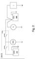
Figure 2 shows a simplified electrical diagram of an automotive dual battery electrical system configured to implement the invention; and -
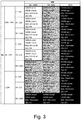
Figure 3 shows a table representing operating conditions in which the automotive dual battery electrical system operates depending on the state of electric charge of the two electrical batteries. - The invention will now be described in detail with reference to the accompanying figures, so as to allow a person skilled in the art to carry it out and to use it. Possible changes to the embodiments described will be immediately evident to skilled people and the generic principles described can be applied to other embodiments and applications without for this reason going beyond the scope of protection of the invention as it is defined in the appended claims. Therefore, the invention cannot be considered as limited to the embodiments described and shown, but is has to be associated with the widest scope of protection possible in accordance with the features described and claimed herein.
-
Figure 1 schematically shows automotive on-board systems of a motor vehicle MV involved in the implementation of the invention and comprising an internal combustion engine ICE, an automotive dual battery electrical system DBES, and an automotive electronic control unit ECU connected to the internal combustion engine ICE and to the automotive dual battery electrical system DBES through an automotive on-board communication network NET, for example a CAN network, a FlexRAy network or the like. -
Figure 2 shows a simplified electrical diagram of a preferred embodiment of the automotive dual battery electrical system DBES. - The automotive dual battery electrical system DBES comprises:
- a main electrical accumulator, hereinafter referred to as main (or service) electrical batter MB, for example a 12 V lead-acid battery,
- a secondary electrical accumulator, hereinafter referred to as auxiliary (or buffer) electrical batter AB, for example a 12 V lithium-ion battery,
- a battery charge status sensor SEN associated with the main battery MB in order to monitor the voltage and the electric current thereof and determine the electric charge status thereof,
- a battery management system BMS associated with the auxiliary batter AB in order to monitor the voltage and the electric current thereof and determine the electric charge status thereof,
- a reversible alternator, more commonly known as belt-driven starter generator BSG, which is coupled to the drive shaft of the internal combustion engine ICE of the motor vehicle MV through a belt and is a reversible electric machine or motor-generator electronically controllable so as to selectively operate as an electric motor, in order to generate an additional mechanical torque to be added to the one generated by the internal combustion engine ICE, and as a traditional alternator, in order to generate electrical energy;
- a starter motor S designed to carry out cold starts of the internal combustion engine of the motor vehicle MV,
- electrical loads L, which represent, as a whole, all the electrically supplied/controlled automotive on-board vehicles, both the safety critical ones and the safety non-critical ones, and
- an electronic switch, hereinafter referred to as dual battery manager DBM, connected among the main and auxiliary batteries MB and AB, belt-driven starter generator BSG and the electrical loads L in order to selectively connect the main and auxiliary batteries MB and AB, belt-driven starter generator BSG, the starter motor S and the electrical loads L to one another in the way described below.
- The electronic control unit ECU is connected to the different automotive on-board systems, to the belt-driven starter generator BSG, to the starter motor S, to the dual battery manager DBM through the automotive on-board communication network NET, to the battery electric charge status sensor SEN through a local interconnection network LIN (not shown), to the battery management system BMS through a local interconnection network LIN or through the automotive on-board communication network NET, and is configured to generate control signals for the belt-driven starter generator BSG, the starter motor S and the dual battery manager DBM in order to properly control the operation thereof, as described more in detail below with reference to what concerns the invention.
- The belt-driven starter generator BSG is electronically controllable by the automotive electronic control unit ECU in order to fulfil a series of functions comprising, among others:
- automatic internal combustion engine stop and start S&S, in which the belt-driven starter generator BSG is operated as an electric motor to start the internal combustion engine ICE after it has been stopped by the automotive electronic control unit ECU in certain running conditions of the motor vehicle MV,
- electric power assist-torque boost (or motoring) EPA, in which the belt-driven starter generator BSG is operated as an electric motor to generate a mechanical torque to supplement the mechanical torque generated by the internal combustion engine ICE,
- regenerative braking RB, in which the belt-driven starter generator BSG is operated as an electrical generator to create a kinetic energy recovery system KERS to recover part of the kinetic energy of the motor vehicle MV during braking and turn it into electrical energy to be used to charge the main and auxiliary batteries MB and AB and/or supply power to the electrical loads L, and
- alternator (A), in which the belt-driven starter generator BSG is operated as a classic alternator, namely as an electrical generator to generate electrical energy.
- The electronic control unit ECU could alternatively be manufactured in the form of an electronic control unit specifically dedicated to the control of the electrical system DBES and, hence, be distinct both from the electronic control unit of the drivetrain and from the electronic control unit of the internal combustion engine and communicate with them through the automotive on-board network NET, or it could be built-in, with these electronic control units, in one single electronic control unit.
- The starter motor S has a first terminal connected to the positive pole of the main battery MB in a direct manner, i.e. without the interposition of other components, and also to the positive pole of the auxiliary batter AB in an indirect manner, through the dual battery manager DBM. The belt-driven starter generator BSG has a first terminal connected to the positive poled of the main battery MB and of the auxiliary batter AB through the dual battery manager DBM.
- The negative poles (-) of the main and auxiliary batteries MB and AB as well as the second terminals of the starter motor S and of the belt-driven starter generator BSG, are connected to the electrical ground of the motor vehicle MV.
- Finally, the electrical loads L are connected to the positive pole of the auxiliary battery AB through an electrical energy distribution stage (not shown), thus being connected also to the positive pole of the main battery MB through the dual battery manager DBM.
- The dual battery manager DBM has a first input/output terminal I/O-1 connected to the positive pole of the main battery MB, a second input/output terminal I/O-2 connected to the positive pole of the auxiliary battery AB, and a third input/output terminal I/O-3 connected to the first terminal of the belt-driven starter generator BGS.
- The dual battery manager DBM comprises two electronically controllable switch devices SWMB and SWAB associated with the main battery MB and with the auxiliary battery AB, respectively, and manufactured by means of relays or solid-state devices. The dual battery manager DBM could also optionally comprise a properly programmed microcontroller.
- The first switch device SWMB is connected in series to the first input/output terminal I/O-1, thus being connected to the positive pole of the main battery MB, whereas the second switch device SWAB is connected in series to the second input/output terminal I/O-2, thus being connected to the positive pole of the auxiliary battery AB. The second switch device SWAB could be a switch device distinct from the auxiliary battery AB or it could consist of a switch device built-in in the auxiliary battery AB.
- The operation state (open or closed) of the switch devices SWMB and SWAB is controlled by the electronic control unit ECU either directly, when the dual battery manager DBM has no microcontroller, or through the microcontroller of the dual battery manager DBM, in both cases based on the information provided by the battery electric charge status sensor SEN and by the battery management system BMS and on status information of the motor vehicle MV provided through the automotive on-board network NET.
- The electronic control unit ECU is further configured to carry out a diagnosis of the dual battery manager DBM aimed at identifying possible faults of the switch devices SWMB and SWAB and of the relative microcontroller, if present, and at implementing specific switching strategies of the switch devices SWMB e SWAB depending on the identified fault, said strategies being not described herein in detail as they are not part of the invention.
- Finally, the electrical energy distribution stage can have different circuit architectures and, in one of them, it controls both safety critical electrical loads and the safety non-critical electrical loads, whereas, in the other one, it supplies power to the safety non-critical electrical loads through the sole main battery MB and to the safety critical electrical loads through one between the main battery MB and the auxiliary batter AB, depending on the operation status (open/close) of the switch devices SWMB and SWAB. This second architecture allows manufacturers to use a smaller auxiliary battery AB in terms of energy capacity and, hence, of dimensions, thus making it easier for it to be installed in the motor vehicles.
- As to the distinction of the electrical loads, the safety critical electrical loads can comprise, by way of non-limiting example, the power steering, the braking system and the sub-systems associated with it, such as the ABS (Antilock Braking System) and the ESP (Electronic Stability Program), the lighting system, the windshield wipers, etc., whereas the safety non-critical electrical loads can comprise, by way of non-limiting example, the infotainment system comprising, among other things, the air conditioning system, etc.
- In a different embodiment, which is not shown herein, the automotive dual battery electrical system could have the architecture described and shown in the aforesaid
EP 2 390 982 A1 of the Applicant. - According to the invention, the electronic control unit ECU is configured to implement a logic for the management of the automotive dual battery electrical system DBES which allowed the Applicant to reach the goals set, namely further improving the efficiency in the management of the electrical energy flow of the dual battery electrical system DBES.
- The management logic according to the invention is basically designed to manage the electrical energy flows in the dual battery electrical system DBES so as to favour the electrical balance of the motor vehicle MV, when needed, and, on the other hand, to minimize the fuel consumption of the motor vehicle MV, when possible.
- The management logic according to the invention will be described hereinafter with reference to
Figure 3 , which shows a table representing the so-called operation plane of the dual battery electrical system DBES, which represents all the electric charge statuses which can be assumed by the main and auxiliary batteries MB and AB as well as the electrical energy demands which can be made by the electrical loads L. - In particular, in the table shown in
Figure 3 , the columns represent the status of charge (SOC) of the main battery MB, whereas the rows represent the status of charge (SOC) of the auxiliary batter AB, both expressed in percentage values relative to the maximum status of charge that can be reached by the main and auxiliary batteries MB and AB. - The status of charge of the main and auxiliary batteries MB and AB are grouped in a given number of electric charge ranges, each delimited, at the bottom and at the top, by a lower electric charge status threshold and by a higher electric charge status threshold and comprising the electric charge statuses comprised between the lower electric charge status threshold and the higher electric charge status threshold.
- In the embodiment represented in the table shown in
Figure 3 , the statuses of electric charge of the main and auxiliary batteries MB and AB are grouped in three electrical charge ranges comprising a lower electric charge range, a higher electric charge range and an intermediate electric charge range. - As far as the main battery is concerned MB, the lower electric charge range comprises the statuses of electric charge below 80%, the intermediate electric charge range comprises the statuses of electric charge comprised between 80% and 85%, and the higher electric charge range comprises the statuses of electric charge comprised between 85% and 100%.
- As far as the auxiliary battery is concerned AB, the lower electric charge range comprises the statuses of electric charge below 30%, the intermediate electric charge range comprises the statuses of electric charge comprised between 30% and 50%, and the higher electric charge range comprises the statuses of electric charge comprised between 50% and 90%.
- The percentage values of the electric charge status thresholds defining the different electric charge ranges at the top and at the bottom and indicated in the table of
Figure 3 are mere examples and depend on different factors which can change from manufacturer to manufacturer, among them there are the type of main and auxiliary batteries MB and AB and the logic for the management of the operation of the automotive dual battery electrical system DBES to be implemented by each manufacturer. - In a different embodiment, the statuses of electric charge of the main and auxiliary batteries MB and AB could be grouped in a different number of electric charge statuses, for example four or more, in which each electric charge range can be divided into two or more electric charge sub-ranges so as to increase the level of detail of the logic for the management of the operation of the dual battery electrical system DBES.
- In the table shown in
Figure 3 , furthermore, each electric charge range of the auxiliary battery AB is associated with a given number of electrical load ranges defined by corresponding sets of values of the electric current absorbed by the loads L. - In particular, in the table shown in
Figure 3 , each electric charge range of the auxiliary battery AB is associated, by mere way of example, with three electrical load ranges comprising a lower range including values of absorbed electric current ranging from 0 to 20 A, an intermediate range including values of absorbed electric current ranging from 20 to 50 A, and a higher range including values of absorbed electric current ranging from 50 to 100 A. - Therefore, the cells of the table shown in
Figure 3 can be identified by three values comprising an electric charge range of the main battery MB, an electric charge range of the auxiliary batter AB, and an electrical energy demand range. - The cells in the table shown in
Figure 3 further indicate the operation statuses (open or closed) of the two switch devices SWMB and SWAB of the dual battery manager DBM, the operation status (electric motor or alternator) of the belt-driven starter generator BSG, the operation status (enabled or disabled) of the engine stop&start functionality, and the operation status (enabled or disabled) of the regenerative braking functionality. - Depending on the operation statuses of the belt-driven starter generator BSG and of the switch devices SWMB and SWAB as well as on the operation statuses of the engine start&stop and regenerative braking functionalities, one of or both the main and auxiliary batteries MB and AB can be electrically charged by the belt-driven starter generator BSG, when it operates as an electrical generator and the regenerative braking functionality is enabled, or when it operates as an alternator, and the internal combustion engine ICE can be restarted by the belt-driven starter generator BSG, when it operates as an electric motor and the engine start&stop functionality is enabled.
- To this regard, in the table shown in
Figure 3 , the cells are coloured with three different shades of grey, a light one, an intermediate one and a dark one, which identify, in the operation plane of the automotive dual battery electrical system DBES, three different operation areas, in which the automotive electronic control unit ECU is programmed to carry out different interventions on the automotive dual battery electrical system DBES in order to favour the electrical balance or minimize the energy consumption of the motor vehicle MV, as described in detail below. - On a quality level, when both the main and the auxiliary batteries MB and AB have reached a sufficient status of electric charge and the electrical energy demand of the loads L permits it, the automotive electronic control unit ECU is programmed to carry out all the interventions available to minimize the energy consumption of the motor vehicle MV (light grey cells). As one of or both the main and auxiliary batteries MB and AB run down below a given electric charge status, the automotive electronic control unit ECU is programmed to progressively reduce the interventions aimed at minimizing the electrical consumption of the motor vehicle MV in order to re-establish the correct electrical balance and avoid an excess discharge of one of or both the main and auxiliary batteries MB and AB (intermediate grey cells). Then, when the electrical energy demand of the loads L exceeds a given threshold or when one of or both the main and auxiliary batteries MB and AB have sufficiently run down, the automotive electronic control unit ECU is programmed to carry out interventions aimed at correctly re-establishing the electrical balance of the automotive dual battery electrical system DBES in order to ensure the correct operation of the motor vehicle MV (dark grey cells).
- From a quantity point of view, the three reference operation areas in the operation plane of the automotive dual battery electrical system DBES comprise:
- a first operation area, which is identified by the cells with a white background and comprises or is defined by:
- electric charge statuses of the main and auxiliary batteries MB and AB belonging to the corresponding higher electric charge ranges, and electrical energy demands of the electrical loads L belonging to any electrical energy demand range, and
- electric charge statuses of the main battery MB belonging to the higher electric charge range, electric charge statuses of the auxiliary battery AB belonging to the intermediate electric charge range, and electrical energy demands of the electrical loads L belonging to either the lower or the intermediate electrical energy demand range;
- a second operation area, which is identified by the cells with a black background and comprises or is defined by:
- electric charge statuses of the main battery MB belonging to the lower electric charge range, electric charge statuses of the auxiliary battery AB belonging to any electric charge range, and electrical energy demands of the electrical loads L belonging to any electrical energy demand range, and
- electric charge statuses of the main battery MB belonging to either the higher or the intermediate electric charge range, electric charge statuses of the auxiliary battery AB belonging to the lower electric charge range, and electrical energy demands of the electrical loads L belonging to the higher electrical energy demand range; and
- a third operation area, which is an area of transition between the first and the second reference operation areas, is identified by the cells with a grey background, and comprises:
- a first subarea, which is defined by:
- ✔ electric charge statuses of the main battery MB belonging to the intermediate electric charge range, electric charge statuses of the auxiliary battery AB belonging to either the higher or the intermediate electric charge range, and electrical energy demands of the electrical loads L belonging to any electrical energy demand range, and
- ✔ electric charge statuses of main battery MB belonging to the higher electric charge range, electric charge statuses of the auxiliary battery AB belonging to the intermediate electric charge range, and electrical energy demands of the electrical loads L belonging to the higher electrical energy demand range;
- a second subarea defined by electric charge statuses of main battery MB belonging to the higher range of electric charge, electric charge statuses of the auxiliary battery AB belonging to the lower electric charge range, and electrical energy demands of the electrical loads L belonging to either the lower or the intermediate electrical energy demand range; and
- a third subarea comprising electric charge statuses of the main battery MB belonging to the intermediate electric charge range, electric charge statuses of the auxiliary battery AB belonging to the lower electric charge range, and electrical energy demands of the loads L belonging to either the lower or the intermediate electrical energy demand range.
- a first subarea, which is defined by:
- The automotive electronic control unit ECU is programmed to determine the operation area in which the automotive dual battery electrical system DBES operates and to carry out different interventions depending on the operation area in which the automotive dual battery electrical system DBES operates, in order to favour the electrical balance of the motor vehicle MV, when needed, and, on the other hand, minimize the energy consumption of the motor vehicle MV, when possible.
- In order to determine the operation area in which the automotive dual battery electrical system DBES operates, the automotive electronic control unit ECU is programmed to determine, first of all, the current operation status of the automotive dual battery electrical system DBES, which is defined by the set of current electric charge statuses of the main and auxiliary batteries MB and AB and by the current electrical energy demand of the electrical loads L, and, thus, to determine which operation area the current operation status of the automotive dual battery electrical system DBES belongs to.
- In particular, if the current operation status of the automotive dual battery electrical system DBES is determined to belong to the first operation area, the automotive electronic control unit ECU is programmed to carry out interventions that allow the fuel consumption of the motor vehicle MV to be minimized.
- If the current operation status of the automotive dual battery electrical system DBES is determined to belong to the second operation area, the automotive electronic control unit ECU is programmed to carry out interventions aimed at re-establishing the electrical balance in order to ensure the correct operation of the motor vehicle MV.
- If, on the other hand, the current operation status of the automotive dual battery electrical system DBES is determined to belong to the third operation area, the automotive electronic control unit ECU is programmed to progressively reduce the interventions carried out in the first operation area and aimed at minimizing the fuel consumption of the motor vehicle MV in order to re-establish the correct electrical balance and avoid an excess discharge of one of or both the main and the auxiliary batteries MB and AB.
- In particular, in the first operation area, which corresponds to relatively high electric charge statuses of the main and auxiliary batteries MB and AB, the automotive electronic control unit ECU is programmed to:
- open the switch device SWMB associated with the main battery MB,
- close the switch device SWAB associated with the auxiliary battery AB,
- enable the electric power assist EPA functionality, so as to cause the belt-driven starter generator BSG to operate, when needed, as an electric motor in order to generate a mechanical power to be added to the one generated by the internal combustion engine ICE,
- enable the regenerative braking RB functionality, so as to cause the belt-driven starter generator BSG to operate, when needed, as an electrical generator in order to recover part of the kinetic energy of the motor vehicle MV during braking, and
- enable the engine stop&start functionality, so as to cause the belt-driven starter generator BSG to operate, when needed, as an electric motor in order to restart the internal combustion engine ICE.
- Therefore, in the first operation area, the main battery MB is electrically disconnected from the belt-driven starter generator BSG and supplies power to the electrical loads L, whereas the auxiliary battery AB is electrically connected to the belt-driven starter generator BSG and, together, they cooperate in the implementation of the engine power assist and regenerative braking RB functionalities.
- In the first operation area, furthermore, the regenerative braking RB functionality electrically charges the sole auxiliary battery AB, as the main battery MB is electrically disconnected from the belt-driven starter generator BSG.
- In the second operation area, which corresponds to relatively low electric charge statuses of the main battery MB, regardless of the electric charge status of the auxiliary battery AB, the automotive electronic control unit ECU is programmed to:
- close the switch device SWMB associated with the main battery MB,
- open the switch device SWAB associated with the auxiliary battery AB,
- enable the alternator (A) functionality, so as to cause the belt-driven starter generator BSG to operate as a classic alternator, namely as an electrical generator, in order to generate electrical energy; and
- disable the engine stop&start functionality, so as to cause the belt-driven starter generator BSG not to operate as an electric motor for the restart of the internal combustion engine ICE.
- Therefore, in the second operation area, the main battery MB is electrically connected to the belt-driven starter generator BSG and supplies power to the electrical loads L, whereas the auxiliary battery AB is electrically disconnected from the belt-driven starter generator BSG.
- In the second operation area, furthermore, the belt-driven starter generator BSG electrically charges the sole main battery MB, as the auxiliary battery AB is electrically disconnected from the belt-driven starter generator BSG.
- In the third operation area, the automotive electronic control unit ECU is programmed to intervene in a different manner on the automotive dual battery electrical system DBES depending on the subarea which the current operation status of the automotive dual battery electrical system DBES is determined to belong to.
- In particular, in the first sub-area, the automotive electronic control unit ECU is programmed to:
- close both the switch device SWMB associated with the main battery MB and the switch device SWAB associated with the auxiliary battery AB,
- enable the regenerative braking RB functionality, but not the electric power assist EPA functionality, so as to cause the belt-driven starter generator BSG to operate, when needed, as an electrical generator in order to recover part of the kinetic energy of the motor vehicle MV during braking, and not to operate as an electric motor in order not to generate an additional mechanical power to be added to the one generated by the internal combustion engine ICE,
- enable the engine stop&start functionality, so as to cause the belt-driven starter generator BSG to operate, when needed, as an electric motor in order to restart the internal combustion engine ICE.
- Therefore, in the first subarea, both the main battery MB and the auxiliary batter AB are electrically connected to the belt-driven starter generator BSG and the electrical energy demands of the electrical loads L and of the belt-driven starter generator BSG during the restart of the internal combustion engine, after it has been temporarily stopped due to the engine start&stop, are fulfilled by both the main and the auxiliary batteries MB and AB, which are electrically charged during the braking of the motor vehicle MV thanks to the enabling of the regenerative braking.
- In the second sub-area, the automotive electronic control unit ECU is programmed to:
- open the switch device SWMB associated with the main battery MB,
- close the switch device SWAB associated with the auxiliary battery AB,
- enable the implementation of the regenerative braking RB functionality, but not the one of the electric power assist EPA functionality, so as to cause the belt-driven starter generator BSG to operate as an electrical generator in order to recover part of the kinetic energy of the motor vehicle MV during braking, and not to operate as an electric motor in order not to generate an additional mechanical power to be added to the one generated by the internal combustion engine ICE, and
- disable the implementation of the engine stop&start functionality, so as to cause the belt-driven starter generator BSG not to operate as an electric motor for the restart of the internal combustion engine ICE.
- Therefore, in the second subarea, the main battery MB is electrically disconnected from the belt-driven starter generator BSG and supplies power to the electrical loads L, whereas the auxiliary battery AB is electrically connected to the belt-driven starter generator BSG and, together, they cooperate in the implementation of the regenerative braking RB functionality.
- In the third subarea, furthermore, the regenerative braking RB functionality electrically charges the sole auxiliary battery AB, as the main battery MB is electrically disconnected from the belt-driven starter generator BSG.
- Finally, in the third sub-area, the automotive electronic control unit ECU is programmed to:
- close the switch device SWMB associated with the main battery MB,
- close the switch device SWAB associated with the auxiliary battery AB,
- enable the implementation of the regenerative braking RB functionality, but not the one of the electric power assist EPA functionality, so as to cause the belt-driven starter generator BSG to operate as an electrical generator in order to recover part of the kinetic energy of the motor vehicle MV during braking, and not to operate as an electric motor in order not to generate an additional mechanical power to be added to the one generated by the internal combustion engine ICE, and
- disable the implementation of the engine stop&start functionality, so as to cause the belt-driven starter generator BSG not to operate as an electric motor for the restart of the internal combustion engine ICE.
- Therefore, in the third subarea, both the main battery MB and the auxiliary batter AB are electrically connected to the belt-driven starter generator BSG and the electrical energy demands of the electrical loads L are fulfilled by both the main and the auxiliary batteries MB and AB, which are electrically charged during the braking of the motor vehicle MV thanks to the enabling of the regenerative braking RB.
- The logic for the management of the operation of the automotive dual battery electrical system according to the invention, as described above, allowed the Applicant to reach the goals set, namely further improving the efficiency in the management of the electrical energy flow in the automotive dual battery electrical system, favouring the electrical balance of the motor vehicle MV, when needed, and, on the other hand, minimizing the energy consumption of the motor vehicle MV, when possible.
Claims (7)
- An automotive electronic control unit (ECU) for a motor vehicle (MV) comprising an internal combustion engine (ICE) and a dual battery electrical system (DBES);
the dual battery electrical system (DBES) comprises:- a main electrical energy source (MB),- an auxiliary electrical energy source (AB),- electrical loads (L),- a belt starter-generator (BSG) operatively coupled to the internal combustion engine (ICE) and electronically controllable to selectively operate as an electric motor to generate a mechanical torque and as an electrical generator to generate electrical energy; and- an electrical switch (DBM) connected among the main and auxiliary electrical energy sources (MB, AB), the belt starter-generator (BSG), and the electrical loads (L), and electronically controllable to selectively connect the main and auxiliary electrical energy sources (MB, AB), the belt starter-generator (BSG) and the electrical loads (L);the automotive electronic control unit (ECU) is configured to be connectable to the dual battery electrical system (DBES) to control the belt starter-generator (BSG) and the electrical switch (DBM) to selectively perform a plurality of functionalities comprising:- automatic internal combustion engine stop and start (S&S), in which the belt starter-generator (BSG) is operated, when needed, as an electric motor to start the internal combustion engine (ICE) after it has been stopped by the automotive electronic control unit (ECU) in certain running conditions of the motor vehicle (MV),- regenerative braking (RB), in which the belt starter-generator (BSG) is operated, when needed, as an electrical generator to recover kinetic energy of the motor vehicle (MV) during braking and transform it into electrical energy,- electric power assist-torque boost or motoring (EPA), in which the belt starter-generator (BSG) is operated, when needed, as an electric motor to generate a mechanical torque to supplement the mechanical torque generated by the internal combustion engine (ICE), and- alternator (A), in which the belt starter-generator (BSG) is operated as an electrical generator to generate electrical energy;wherein the operation status of the dual battery electrical system (DBES) is representable by means of an operation plane representative of the electric charge statuses of the main and auxiliary electrical energy sources (MB, AB) and of the electrical energy demands that can be made by the electrical loads (L),
and wherein the operation plane of the dual battery electrical system (DBES) comprises different operation areas comprising:- a first operation area comprising relatively high electric charge statuses of the main and auxiliary electrical energy sources (MB, AB),- a second operation area comprising relatively low electric charge statuses of the main electrical energy source (MB), and- a third operation area comprising electric charge statuses of the main and auxiliary electrical energy sources (MB, AB) not included in the first and second operation areas;wherein the automotive electronic control unit (ECU) is characterized in that it is further configured to:- determine the current operation status of the dual battery electrical system (DBES) defined by the current electric charge statuses of the main and auxiliary electrical energy sources (MB, AB) and by the current electrical energy demand of the electrical loads (L),- determine which operation area the current operation status of the dual battery electrical system (DBES) belongs to, and- control the operation of the dual battery electrical system (DBES), and enable or disable the implementation of one or more of the functionalities of electric power assist (EPA), regenerative braking (RB), and automatic internal combustion engine stop and start of the (S&S) depending on the operation area which the current operation status of the dual battery electrical system (DBES) belongs to;the automotive electronic control unit (ECU) is further characterized in that it is configured to cause:- when the current operation status of the dual battery electrical system (DBES) is determined to belong to the first operation area, the electrical switch (DBM) to electrically disconnect the main electrical energy source (MB) from the belt starter-generator (BSG) and to electrically connect the auxiliary electrical energy source (AB) to the belt starter-generator (BSG), and the functionalities of electric power assist (EPA), regenerative braking (RB) and automatic internal combustion engine stop and start (S&S) to be enabled,- when the current operation status of the dual battery electrical system (DBES) is determined to belong to the second operation area, the electrical switch (DBM) to electrically connect the main electrical energy source (MB) to the belt starter-generator (BSG) and to electrically disconnect the auxiliary electrical energy source (AB) from the belt starter-generator (BSG), the functionality of alternator (A) to be enabled, and the functionality of automatic internal combustion engine stop and start (S&S) to be disabled, and- when the current operation status of the dual battery electrical system (DBES) is determined to belong to the third operation area, to cause one of the following interventions to be implemented depending on the electric charge statuses of the main and auxiliary electrical energy sources (MB, AB) and on the electric energy demand of the electrical loads (L):✔ the electrical switch (DBM) to electrically connect both the main electrical energy source (MB) and the auxiliary electrical energy source (AB) to the belt starter-generator (BSG), and the functionalities of regenerative braking (RB) and automatic internal combustion engine stop and start (S&S) to be enabled,✔ the electrical switch (DBM) to electrically disconnect the main electrical energy source (MB) from the belt starter-generator (BSG) and to electrically connect the auxiliary electrical energy source (AB) to the belt starter-generator (BSG), the functionality of regenerative braking (RB) to be enabled, and the functionality of automatic internal combustion engine stop and start (S&S) to be disabled, and✔ the electrical switch (DBM) to electrically connect both the main electrical energy source (MB) and the auxiliary electrical energy source (AB) to the belt starter-generator (BSG), the functionality of regenerative braking (RB) to be enabled, and the automatic internal combustion engine stop and start (S&S) to be disabled. - The automotive electronic control unit (ECU) as claimed in claim 1, wherein the electric charge statuses of the main electrical energy source (MB) and of the auxiliary electrical energy source (AB) are grouped in corresponding electric charge ranges comprising a lower electric charge range, a higher electric charge range and an intermediate electric charge range;
wherein the electrical energy demands of the electrical loads (L) are grouped in electrical energy ranges comprising a lower electrical energy demand range, a higher electrical energy demand range and an intermediate electrical energy demand range;
wherein the first operation area comprises:- electric charge statuses of the main and auxiliary electrical energy sources (MB, AB) belonging to the corresponding higher electric charge ranges, and electrical energy demands of the electrical loads (L) belonging to any electrical energy demand range, and- electric charge statuses of the main electrical energy source (MB) belonging to the higher electric charge range, electric charge statuses of the auxiliary electrical energy source (AB) belonging to the intermediate electric charge range, and electrical energy demands of the electrical loads (L) belonging to either the lower or the intermediate electrical energy demand range;wherein the second operation area comprises:- electric charge statuses of the main electrical energy source (MB) belonging to the lower electric charge range, electric charge statuses of the auxiliary electrical energy source (AB) belonging to any electric charge range, and electrical energy demands of the electrical loads (L) belonging to any electrical energy demand range, and- electric charge statuses of the main electrical energy source (MB) belonging to either the higher or the intermediate electric charge range, electric charge statuses of the auxiliary electrical energy source (AB) belonging to the lower electric charge range, and electrical energy demands of the electrical loads (L) belonging to the higher electrical energy demand range;wherein the third operation area comprises:- a first subarea comprising:✔ electric charge statuses of the main electrical energy source (MB) belonging to the intermediate electric charge range, electric charge statuses of the auxiliary electrical energy (AB) belonging to either the higher or the intermediate electrical charge range, and electrical energy demands of the electrical loads (L) belonging to any electrical energy demand range, and✔ electric charge statuses of main electrical energy source (MB) belonging to the higher electric charge range, electric charge statuses of the auxiliary electrical energy source (AB) belonging to the intermediate electric charge range, and electrical energy demands of the electrical loads (L) belonging to the higher electrical energy demand range;- a second subarea comprising electric charge statuses of main electrical energy source (MB) belonging to the higher range of electric charge, electric charge statuses of the auxiliary electrical energy source (AB) belonging to the lower electric charge range, and electrical energy demands of the electrical loads (L) belonging to either the lower or the intermediate electrical energy demand range; and- a third subarea comprising electric charge statuses of the main electrical energy source (MB) belonging to the intermediate electric charge range, electric charge statuses of the auxiliary electrical energy source (AB) belonging to the lower electric charge range, and electrical energy demands of the loads (L) belonging to either the lower or the intermediate electrical energy demand range. - The automotive electronic control unit (ECU) as claimed in claim 2, further configured to cause, when the current operation status of the dual battery electrical system (DBES) is determined to belong to the third operation area:- in the first subarea, the electrical switch (DBM) to electrically connect both the main electrical energy source (MB) and the auxiliary electrical energy source (AB) to the belt starter-generator (BSG), and the functionalities of regenerative braking (RB) and automatic internal combustion engine stop and start (S&S) to be enabled,- in the second subarea, the electrical switch (DBM) to electrically disconnect the main electrical energy source (MB) from the belt starter-generator (BSG) and to electrically connect the auxiliary electrical energy source (AB) to the belt starter-generator (BSG), the functionality of regenerative braking (RB) to be enabled, and the functionality of automatic internal combustion engine stop and start (S&S) to be disabled, and- in the third subarea, the electrical switch (DBM) to electrically connect both the main electrical energy source (MB) and the auxiliary electrical energy source (AB) to the belt starter-generator (BSG), the functionality of regenerative braking (RB) to be enabled, and the functionality of automatic internal combustion engine stop and start (S&S) to be disabled.
- The automotive electronic control unit (ECU) as claimed in any one of the preceding claims, wherein a lower electric charge range is defined by electric charge statuses lower than a lower electric charge threshold, a higher electric charge range is defined by electric charge statuses higher than a higher electric charge threshold, and an intermediate electric charge range is defined by electric charge statuses between the lower and higher electric charges thresholds.
- Software loadable in an automotive electronic control unit (ECU) and designed to cause, when executed, the automotive electronic control unit (ECU) to become configured as claimed in any one of the preceding claims.
- An automotive dual battery electrical system (DBES) for a motor vehicle (MV) comprising an internal combustion engine (ICE);
the automotive dual battery electrical system (DBES) comprises:- a main electrical energy source (MB),- an auxiliary electrical energy source (AB),- electrical loads (L),- a belt starter-generator (BSG) coupled to the internal combustion engine (ICE) and electronically controllable to selectively operate as an electric motor to generate a mechanical torque and as an alternator to generate electrical energy,- an electrical switch (DBM) connected among the main and auxiliary electrical energy sources (MB, AB), the belt starter-generator (BSG), and the electric loads (L), and electronically controllable to selectively connect the auxiliary main electrical energy sources (MB, AB), the belt starter-generator (BSG) and the electrical loads (L), and- an automotive electronic control unit (ECU) as claimed in any one of the preceding claims 1 to 4. - A motor vehicle (MV) comprising an internal combustion engine (ICE) and a dual battery electrical system (DBES) as claimed in claim 6.
Applications Claiming Priority (1)
| Application Number | Priority Date | Filing Date | Title |
|---|---|---|---|
| IT102018000002823A IT201800002823A1 (en) | 2018-02-19 | 2018-02-19 | OPERATION MANAGEMENT OF A DOUBLE BATTERY AUTOMOTIVE ELECTRIC SYSTEM WITH KINETIC ENERGY RECOVERY DURING BRAKING |
Publications (2)
| Publication Number | Publication Date |
|---|---|
| EP3527419A1 true EP3527419A1 (en) | 2019-08-21 |
| EP3527419B1 EP3527419B1 (en) | 2020-05-27 |
Family
ID=62218206
Family Applications (1)
| Application Number | Title | Priority Date | Filing Date |
|---|---|---|---|
| EP18215959.0A Active EP3527419B1 (en) | 2018-02-19 | 2018-12-31 | Management of the operation of an automotive dual battery electrical system |
Country Status (3)
| Country | Link |
|---|---|
| US (1) | US10850724B2 (en) |
| EP (1) | EP3527419B1 (en) |
| IT (1) | IT201800002823A1 (en) |
Cited By (1)
| Publication number | Priority date | Publication date | Assignee | Title |
|---|---|---|---|---|
| EP4424984A1 (en) * | 2023-03-03 | 2024-09-04 | Volvo Truck Corporation | Method for operating a vehicle and vehicle operated by such a method |
Families Citing this family (3)
| Publication number | Priority date | Publication date | Assignee | Title |
|---|---|---|---|---|
| JP6540565B2 (en) * | 2016-03-16 | 2019-07-10 | 株式会社オートネットワーク技術研究所 | Power supply system for vehicle, drive system for vehicle |
| WO2022106971A1 (en) * | 2020-11-17 | 2022-05-27 | Accelerated Systems Inc. | Electric vehicles with battery management and sensors |
| US20220281409A1 (en) * | 2021-03-02 | 2022-09-08 | Dana Bellah | Enhanced automotive electrical battery system |
Citations (5)
| Publication number | Priority date | Publication date | Assignee | Title |
|---|---|---|---|---|
| EP2390982A1 (en) | 2010-05-25 | 2011-11-30 | Fiat Group Automobiles S.p.A. | Automotive electrical system operation management during coasting and/or with engine off |
| EP2595278A1 (en) | 2011-11-16 | 2013-05-22 | C.R.F. Società Consortile per Azioni | Management of operation of an automotive electrical system featuring a renewable electrical power source |
| EP2638614A2 (en) | 2010-11-12 | 2013-09-18 | Fiat Group Automobiles S.p.A. | Automotive electrical system provided with an alternator electronic control system |
| WO2014025069A1 (en) | 2012-08-10 | 2014-02-13 | Denso Corporation | Power system for a vehicle |
| WO2015016965A1 (en) | 2013-07-31 | 2015-02-05 | Johnson Controls Technology Company | Passive architectures for batteries having two different chemistries |
Family Cites Families (16)
| Publication number | Priority date | Publication date | Assignee | Title |
|---|---|---|---|---|
| US6591758B2 (en) * | 2001-03-27 | 2003-07-15 | General Electric Company | Hybrid energy locomotive electrical power storage system |
| CN101309810B (en) * | 2005-09-23 | 2012-07-04 | Afs三一电力公司 | Method and apparatus for power electronics and control of plug-in hybrid propulsion with fast energy storage |
| GB2458677B (en) * | 2008-03-27 | 2012-08-08 | Ford Global Tech Llc | Dual battery vehicle electrical systems |
| US8049362B2 (en) * | 2008-08-29 | 2011-11-01 | Lear Corporation | Vehicle inverter |
| GB0918384D0 (en) * | 2009-10-20 | 2009-12-02 | Ricardo Uk Ltd | A dual-mode battery |
| US8647231B2 (en) * | 2010-07-07 | 2014-02-11 | Ford Global Technologies, Llc | Transitioning between electric-drive and parallel-drive in a hybrid-electric vehicle powertrain |
| US9669724B2 (en) * | 2012-08-31 | 2017-06-06 | Johnson Controls Technology Center | Optimized fuzzy logic controller for energy management in micro and mild hybrid electric vehicles |
| US10106038B2 (en) * | 2012-12-28 | 2018-10-23 | Johnson Controls Technology Company | Dual function battery system and method |
| US20150032301A1 (en) * | 2013-07-29 | 2015-01-29 | Electro-Motive Diesel, Inc. | Two tiered energy storage for a mobile vehicle |
| CN104417346B (en) * | 2013-09-09 | 2017-04-12 | 比亚迪股份有限公司 | Control system and control method of hybrid electrical vehicle (HEV) |
| TWI542487B (en) * | 2014-03-12 | 2016-07-21 | 國立臺灣師範大學 | Transportation |
| US10320202B2 (en) * | 2014-09-30 | 2019-06-11 | Johnson Controls Technology Company | Battery system bi-stable relay control |
| US9776635B2 (en) * | 2015-02-09 | 2017-10-03 | Ford Global Technologies, Llc | Apparatus and method to maximize vehicle functionality and fuel economy with improved drivability during engine auto stop-start operations |
| WO2017079666A1 (en) * | 2015-11-04 | 2017-05-11 | Johnson Controls Technology Company | Optimization of cruising voltage for life and fuel economy performance in advanced start-stop systems |
| US20180372200A1 (en) * | 2015-12-15 | 2018-12-27 | Dana Limited | Control strategies for hybrid electric powertrain configurations with a ball variator used as a powersplit e-cvt |
| US10118605B2 (en) * | 2017-03-13 | 2018-11-06 | Ford Global Technologies, Llc | Methods and system for a hybrid vehicle |
-
2018
- 2018-02-19 IT IT102018000002823A patent/IT201800002823A1/en unknown
- 2018-12-28 US US16/235,260 patent/US10850724B2/en active Active
- 2018-12-31 EP EP18215959.0A patent/EP3527419B1/en active Active
Patent Citations (6)
| Publication number | Priority date | Publication date | Assignee | Title |
|---|---|---|---|---|
| EP2390982A1 (en) | 2010-05-25 | 2011-11-30 | Fiat Group Automobiles S.p.A. | Automotive electrical system operation management during coasting and/or with engine off |
| EP2638614A2 (en) | 2010-11-12 | 2013-09-18 | Fiat Group Automobiles S.p.A. | Automotive electrical system provided with an alternator electronic control system |
| EP2595278A1 (en) | 2011-11-16 | 2013-05-22 | C.R.F. Società Consortile per Azioni | Management of operation of an automotive electrical system featuring a renewable electrical power source |
| WO2014025069A1 (en) | 2012-08-10 | 2014-02-13 | Denso Corporation | Power system for a vehicle |
| WO2015016965A1 (en) | 2013-07-31 | 2015-02-05 | Johnson Controls Technology Company | Passive architectures for batteries having two different chemistries |
| EP3028336A1 (en) * | 2013-07-31 | 2016-06-08 | Johnson Controls Technology Company | Passive architectures for batteries having two different chemistries |
Cited By (2)
| Publication number | Priority date | Publication date | Assignee | Title |
|---|---|---|---|---|
| EP4424984A1 (en) * | 2023-03-03 | 2024-09-04 | Volvo Truck Corporation | Method for operating a vehicle and vehicle operated by such a method |
| US12473881B2 (en) | 2023-03-03 | 2025-11-18 | Volvo Truck Corporation | Method for operating a vehicle and vehicle operated by such a method |
Also Published As
| Publication number | Publication date |
|---|---|
| IT201800002823A1 (en) | 2019-08-19 |
| US20190256076A1 (en) | 2019-08-22 |
| EP3527419B1 (en) | 2020-05-27 |
| US10850724B2 (en) | 2020-12-01 |
Similar Documents
| Publication | Publication Date | Title |
|---|---|---|
| US10766368B2 (en) | Dual function battery system and method | |
| CN107176160B (en) | System and method for powering start-stop and hybrid vehicle components and accessories | |
| EP3218221B1 (en) | Semi-active partial parallel battery configuration for an vehicle system and method | |
| US10703210B2 (en) | Method of controlling a mild hybrid electric vehicle | |
| US9855904B2 (en) | Coupling store device for a motor vehicle | |
| EP3527419B1 (en) | Management of the operation of an automotive dual battery electrical system | |
| US10547089B2 (en) | Optimization of cruising voltage for life and fuel economy performance in advanced start-stop systems | |
| CN102582459A (en) | Method and apparatus for electric power management in a vehicle | |
| CN105431975B (en) | For having the switch passive structures of the battery there are two types of different chemical composition | |
| CN107107772A (en) | The bistable relay control of battery system | |
| CN104052104A (en) | Vehicle-mounted power supply system | |
| EP2773526A2 (en) | A dual energy storage system for micro hybrid vehicles | |
| GB2536559A (en) | Apparatus and method to maximize vehicle functionality and fuel economy with improved drivability during engine auto stop-start operations | |
| CN105637700A (en) | Passive structure for batteries with two different chemistries | |
| JP2017212808A (en) | Power supply device for vehicle | |
| JP2011163281A (en) | Idling stop vehicle | |
| JP2015180140A (en) | Vehicle power supply system | |
| CN114389323A (en) | Method for reducing the total power consumption of a parked vehicle | |
| CN105431976B (en) | Semi-active structure for batteries with two different chemistries | |
| JP5598216B2 (en) | Vehicle power supply control device | |
| JP6560713B2 (en) | Vehicle power supply | |
| JP2011163282A (en) | Power source device for vehicle | |
| CN211075554U (en) | Self-circulation charging and discharging device and power assembly system of electric automobile | |
| US12337774B2 (en) | Dual voltage electrical architecture for a vehicle, in which the only power source is a lithium-ion battery | |
| CN114701477B (en) | Hybrid electric vehicle low temperature starting control method and control system |
Legal Events
| Date | Code | Title | Description |
|---|---|---|---|
| PUAI | Public reference made under article 153(3) epc to a published international application that has entered the european phase |
Free format text: ORIGINAL CODE: 0009012 |
|
| STAA | Information on the status of an ep patent application or granted ep patent |
Free format text: STATUS: REQUEST FOR EXAMINATION WAS MADE |
|
| 17P | Request for examination filed |
Effective date: 20181231 |
|
| AK | Designated contracting states |
Kind code of ref document: A1 Designated state(s): AL AT BE BG CH CY CZ DE DK EE ES FI FR GB GR HR HU IE IS IT LI LT LU LV MC MK MT NL NO PL PT RO RS SE SI SK SM TR |
|
| AX | Request for extension of the european patent |
Extension state: BA ME |
|
| GRAP | Despatch of communication of intention to grant a patent |
Free format text: ORIGINAL CODE: EPIDOSNIGR1 |
|
| STAA | Information on the status of an ep patent application or granted ep patent |
Free format text: STATUS: GRANT OF PATENT IS INTENDED |
|
| INTG | Intention to grant announced |
Effective date: 20191209 |
|
| GRAS | Grant fee paid |
Free format text: ORIGINAL CODE: EPIDOSNIGR3 |
|
| GRAA | (expected) grant |
Free format text: ORIGINAL CODE: 0009210 |
|
| STAA | Information on the status of an ep patent application or granted ep patent |
Free format text: STATUS: THE PATENT HAS BEEN GRANTED |
|
| AK | Designated contracting states |
Kind code of ref document: B1 Designated state(s): AL AT BE BG CH CY CZ DE DK EE ES FI FR GB GR HR HU IE IS IT LI LT LU LV MC MK MT NL NO PL PT RO RS SE SI SK SM TR |
|
| REG | Reference to a national code |
Ref country code: GB Ref legal event code: FG4D |
|
| REG | Reference to a national code |
Ref country code: CH Ref legal event code: EP |
|
| REG | Reference to a national code |
Ref country code: AT Ref legal event code: REF Ref document number: 1274219 Country of ref document: AT Kind code of ref document: T Effective date: 20200615 |
|
| REG | Reference to a national code |
Ref country code: DE Ref legal event code: R096 Ref document number: 602018004915 Country of ref document: DE |
|
| REG | Reference to a national code |
Ref country code: LT Ref legal event code: MG4D |
|
| PG25 | Lapsed in a contracting state [announced via postgrant information from national office to epo] |
Ref country code: PT Free format text: LAPSE BECAUSE OF FAILURE TO SUBMIT A TRANSLATION OF THE DESCRIPTION OR TO PAY THE FEE WITHIN THE PRESCRIBED TIME-LIMIT Effective date: 20200928 Ref country code: FI Free format text: LAPSE BECAUSE OF FAILURE TO SUBMIT A TRANSLATION OF THE DESCRIPTION OR TO PAY THE FEE WITHIN THE PRESCRIBED TIME-LIMIT Effective date: 20200527 Ref country code: IS Free format text: LAPSE BECAUSE OF FAILURE TO SUBMIT A TRANSLATION OF THE DESCRIPTION OR TO PAY THE FEE WITHIN THE PRESCRIBED TIME-LIMIT Effective date: 20200927 Ref country code: GR Free format text: LAPSE BECAUSE OF FAILURE TO SUBMIT A TRANSLATION OF THE DESCRIPTION OR TO PAY THE FEE WITHIN THE PRESCRIBED TIME-LIMIT Effective date: 20200828 Ref country code: SE Free format text: LAPSE BECAUSE OF FAILURE TO SUBMIT A TRANSLATION OF THE DESCRIPTION OR TO PAY THE FEE WITHIN THE PRESCRIBED TIME-LIMIT Effective date: 20200527 Ref country code: NO Free format text: LAPSE BECAUSE OF FAILURE TO SUBMIT A TRANSLATION OF THE DESCRIPTION OR TO PAY THE FEE WITHIN THE PRESCRIBED TIME-LIMIT Effective date: 20200827 Ref country code: LT Free format text: LAPSE BECAUSE OF FAILURE TO SUBMIT A TRANSLATION OF THE DESCRIPTION OR TO PAY THE FEE WITHIN THE PRESCRIBED TIME-LIMIT Effective date: 20200527 |
|
| REG | Reference to a national code |
Ref country code: NL Ref legal event code: MP Effective date: 20200527 |
|
| PG25 | Lapsed in a contracting state [announced via postgrant information from national office to epo] |
Ref country code: BG Free format text: LAPSE BECAUSE OF FAILURE TO SUBMIT A TRANSLATION OF THE DESCRIPTION OR TO PAY THE FEE WITHIN THE PRESCRIBED TIME-LIMIT Effective date: 20200827 Ref country code: LV Free format text: LAPSE BECAUSE OF FAILURE TO SUBMIT A TRANSLATION OF THE DESCRIPTION OR TO PAY THE FEE WITHIN THE PRESCRIBED TIME-LIMIT Effective date: 20200527 Ref country code: RS Free format text: LAPSE BECAUSE OF FAILURE TO SUBMIT A TRANSLATION OF THE DESCRIPTION OR TO PAY THE FEE WITHIN THE PRESCRIBED TIME-LIMIT Effective date: 20200527 Ref country code: HR Free format text: LAPSE BECAUSE OF FAILURE TO SUBMIT A TRANSLATION OF THE DESCRIPTION OR TO PAY THE FEE WITHIN THE PRESCRIBED TIME-LIMIT Effective date: 20200527 |
|
| REG | Reference to a national code |
Ref country code: AT Ref legal event code: MK05 Ref document number: 1274219 Country of ref document: AT Kind code of ref document: T Effective date: 20200527 |
|
| PG25 | Lapsed in a contracting state [announced via postgrant information from national office to epo] |
Ref country code: NL Free format text: LAPSE BECAUSE OF FAILURE TO SUBMIT A TRANSLATION OF THE DESCRIPTION OR TO PAY THE FEE WITHIN THE PRESCRIBED TIME-LIMIT Effective date: 20200527 Ref country code: AL Free format text: LAPSE BECAUSE OF FAILURE TO SUBMIT A TRANSLATION OF THE DESCRIPTION OR TO PAY THE FEE WITHIN THE PRESCRIBED TIME-LIMIT Effective date: 20200527 |
|
| PG25 | Lapsed in a contracting state [announced via postgrant information from national office to epo] |
Ref country code: SM Free format text: LAPSE BECAUSE OF FAILURE TO SUBMIT A TRANSLATION OF THE DESCRIPTION OR TO PAY THE FEE WITHIN THE PRESCRIBED TIME-LIMIT Effective date: 20200527 Ref country code: AT Free format text: LAPSE BECAUSE OF FAILURE TO SUBMIT A TRANSLATION OF THE DESCRIPTION OR TO PAY THE FEE WITHIN THE PRESCRIBED TIME-LIMIT Effective date: 20200527 Ref country code: DK Free format text: LAPSE BECAUSE OF FAILURE TO SUBMIT A TRANSLATION OF THE DESCRIPTION OR TO PAY THE FEE WITHIN THE PRESCRIBED TIME-LIMIT Effective date: 20200527 Ref country code: EE Free format text: LAPSE BECAUSE OF FAILURE TO SUBMIT A TRANSLATION OF THE DESCRIPTION OR TO PAY THE FEE WITHIN THE PRESCRIBED TIME-LIMIT Effective date: 20200527 Ref country code: RO Free format text: LAPSE BECAUSE OF FAILURE TO SUBMIT A TRANSLATION OF THE DESCRIPTION OR TO PAY THE FEE WITHIN THE PRESCRIBED TIME-LIMIT Effective date: 20200527 Ref country code: ES Free format text: LAPSE BECAUSE OF FAILURE TO SUBMIT A TRANSLATION OF THE DESCRIPTION OR TO PAY THE FEE WITHIN THE PRESCRIBED TIME-LIMIT Effective date: 20200527 Ref country code: CZ Free format text: LAPSE BECAUSE OF FAILURE TO SUBMIT A TRANSLATION OF THE DESCRIPTION OR TO PAY THE FEE WITHIN THE PRESCRIBED TIME-LIMIT Effective date: 20200527 |
|
| PG25 | Lapsed in a contracting state [announced via postgrant information from national office to epo] |
Ref country code: SK Free format text: LAPSE BECAUSE OF FAILURE TO SUBMIT A TRANSLATION OF THE DESCRIPTION OR TO PAY THE FEE WITHIN THE PRESCRIBED TIME-LIMIT Effective date: 20200527 Ref country code: PL Free format text: LAPSE BECAUSE OF FAILURE TO SUBMIT A TRANSLATION OF THE DESCRIPTION OR TO PAY THE FEE WITHIN THE PRESCRIBED TIME-LIMIT Effective date: 20200527 |
|
| REG | Reference to a national code |
Ref country code: DE Ref legal event code: R097 Ref document number: 602018004915 Country of ref document: DE |
|
| PLBE | No opposition filed within time limit |
Free format text: ORIGINAL CODE: 0009261 |
|
| STAA | Information on the status of an ep patent application or granted ep patent |
Free format text: STATUS: NO OPPOSITION FILED WITHIN TIME LIMIT |
|
| 26N | No opposition filed |
Effective date: 20210302 |
|
| PG25 | Lapsed in a contracting state [announced via postgrant information from national office to epo] |
Ref country code: MC Free format text: LAPSE BECAUSE OF FAILURE TO SUBMIT A TRANSLATION OF THE DESCRIPTION OR TO PAY THE FEE WITHIN THE PRESCRIBED TIME-LIMIT Effective date: 20200527 |
|
| REG | Reference to a national code |
Ref country code: BE Ref legal event code: MM Effective date: 20201231 |
|
| PG25 | Lapsed in a contracting state [announced via postgrant information from national office to epo] |
Ref country code: LU Free format text: LAPSE BECAUSE OF NON-PAYMENT OF DUE FEES Effective date: 20201231 Ref country code: IE Free format text: LAPSE BECAUSE OF NON-PAYMENT OF DUE FEES Effective date: 20201231 |
|
| PG25 | Lapsed in a contracting state [announced via postgrant information from national office to epo] |
Ref country code: TR Free format text: LAPSE BECAUSE OF FAILURE TO SUBMIT A TRANSLATION OF THE DESCRIPTION OR TO PAY THE FEE WITHIN THE PRESCRIBED TIME-LIMIT Effective date: 20200527 Ref country code: MT Free format text: LAPSE BECAUSE OF FAILURE TO SUBMIT A TRANSLATION OF THE DESCRIPTION OR TO PAY THE FEE WITHIN THE PRESCRIBED TIME-LIMIT Effective date: 20200527 Ref country code: CY Free format text: LAPSE BECAUSE OF FAILURE TO SUBMIT A TRANSLATION OF THE DESCRIPTION OR TO PAY THE FEE WITHIN THE PRESCRIBED TIME-LIMIT Effective date: 20200527 |
|
| PG25 | Lapsed in a contracting state [announced via postgrant information from national office to epo] |
Ref country code: MK Free format text: LAPSE BECAUSE OF FAILURE TO SUBMIT A TRANSLATION OF THE DESCRIPTION OR TO PAY THE FEE WITHIN THE PRESCRIBED TIME-LIMIT Effective date: 20200527 |
|
| PG25 | Lapsed in a contracting state [announced via postgrant information from national office to epo] |
Ref country code: BE Free format text: LAPSE BECAUSE OF NON-PAYMENT OF DUE FEES Effective date: 20201231 |
|
| REG | Reference to a national code |
Ref country code: CH Ref legal event code: PL |
|
| PG25 | Lapsed in a contracting state [announced via postgrant information from national office to epo] |
Ref country code: LI Free format text: LAPSE BECAUSE OF NON-PAYMENT OF DUE FEES Effective date: 20211231 Ref country code: CH Free format text: LAPSE BECAUSE OF NON-PAYMENT OF DUE FEES Effective date: 20211231 |
|
| GBPC | Gb: european patent ceased through non-payment of renewal fee |
Effective date: 20221231 |
|
| PG25 | Lapsed in a contracting state [announced via postgrant information from national office to epo] |
Ref country code: SI Free format text: LAPSE BECAUSE OF FAILURE TO SUBMIT A TRANSLATION OF THE DESCRIPTION OR TO PAY THE FEE WITHIN THE PRESCRIBED TIME-LIMIT Effective date: 20200527 |
|
| PG25 | Lapsed in a contracting state [announced via postgrant information from national office to epo] |
Ref country code: GB Free format text: LAPSE BECAUSE OF NON-PAYMENT OF DUE FEES Effective date: 20221231 |
|
| PGFP | Annual fee paid to national office [announced via postgrant information from national office to epo] |
Ref country code: DE Payment date: 20251126 Year of fee payment: 8 |
|
| PGFP | Annual fee paid to national office [announced via postgrant information from national office to epo] |
Ref country code: IT Payment date: 20251119 Year of fee payment: 8 |
|
| PGFP | Annual fee paid to national office [announced via postgrant information from national office to epo] |
Ref country code: FR Payment date: 20251119 Year of fee payment: 8 |