EP3527390A1 - Vorrichtung zur justage eines druckkopfs - Google Patents
Vorrichtung zur justage eines druckkopfs Download PDFInfo
- Publication number
- EP3527390A1 EP3527390A1 EP18156645.6A EP18156645A EP3527390A1 EP 3527390 A1 EP3527390 A1 EP 3527390A1 EP 18156645 A EP18156645 A EP 18156645A EP 3527390 A1 EP3527390 A1 EP 3527390A1
- Authority
- EP
- European Patent Office
- Prior art keywords
- screw
- spring
- holder
- printhead
- cone
- Prior art date
- Legal status (The legal status is an assumption and is not a legal conclusion. Google has not performed a legal analysis and makes no representation as to the accuracy of the status listed.)
- Granted
Links
Images

Classifications
-
- B—PERFORMING OPERATIONS; TRANSPORTING
- B41—PRINTING; LINING MACHINES; TYPEWRITERS; STAMPS
- B41J—TYPEWRITERS; SELECTIVE PRINTING MECHANISMS, i.e. MECHANISMS PRINTING OTHERWISE THAN FROM A FORME; CORRECTION OF TYPOGRAPHICAL ERRORS
- B41J25/00—Actions or mechanisms not otherwise provided for
- B41J25/001—Mechanisms for bodily moving print heads or carriages parallel to the paper surface
-
- B—PERFORMING OPERATIONS; TRANSPORTING
- B41—PRINTING; LINING MACHINES; TYPEWRITERS; STAMPS
- B41F—PRINTING MACHINES OR PRESSES
- B41F33/00—Indicating, counting, warning, control or safety devices
-
- B—PERFORMING OPERATIONS; TRANSPORTING
- B41—PRINTING; LINING MACHINES; TYPEWRITERS; STAMPS
- B41J—TYPEWRITERS; SELECTIVE PRINTING MECHANISMS, i.e. MECHANISMS PRINTING OTHERWISE THAN FROM A FORME; CORRECTION OF TYPOGRAPHICAL ERRORS
- B41J2/00—Typewriters or selective printing mechanisms characterised by the printing or marking process for which they are designed
- B41J2/005—Typewriters or selective printing mechanisms characterised by the printing or marking process for which they are designed characterised by bringing liquid or particles selectively into contact with a printing material
- B41J2/01—Ink jet
-
- B—PERFORMING OPERATIONS; TRANSPORTING
- B41—PRINTING; LINING MACHINES; TYPEWRITERS; STAMPS
- B41J—TYPEWRITERS; SELECTIVE PRINTING MECHANISMS, i.e. MECHANISMS PRINTING OTHERWISE THAN FROM A FORME; CORRECTION OF TYPOGRAPHICAL ERRORS
- B41J2/00—Typewriters or selective printing mechanisms characterised by the printing or marking process for which they are designed
- B41J2/005—Typewriters or selective printing mechanisms characterised by the printing or marking process for which they are designed characterised by bringing liquid or particles selectively into contact with a printing material
- B41J2/01—Ink jet
- B41J2/015—Ink jet characterised by the jet generation process
- B41J2/04—Ink jet characterised by the jet generation process generating single droplets or particles on demand
- B41J2/045—Ink jet characterised by the jet generation process generating single droplets or particles on demand by pressure, e.g. electromechanical transducers
- B41J2/04501—Control methods or devices therefor, e.g. driver circuits, control circuits
- B41J2/04505—Control methods or devices therefor, e.g. driver circuits, control circuits aiming at correcting alignment
-
- B—PERFORMING OPERATIONS; TRANSPORTING
- B41—PRINTING; LINING MACHINES; TYPEWRITERS; STAMPS
- B41J—TYPEWRITERS; SELECTIVE PRINTING MECHANISMS, i.e. MECHANISMS PRINTING OTHERWISE THAN FROM A FORME; CORRECTION OF TYPOGRAPHICAL ERRORS
- B41J29/00—Details of, or accessories for, typewriters or selective printing mechanisms not otherwise provided for
- B41J29/38—Drives, motors, controls or automatic cut-off devices for the entire printing mechanism
-
- B—PERFORMING OPERATIONS; TRANSPORTING
- B41—PRINTING; LINING MACHINES; TYPEWRITERS; STAMPS
- B41J—TYPEWRITERS; SELECTIVE PRINTING MECHANISMS, i.e. MECHANISMS PRINTING OTHERWISE THAN FROM A FORME; CORRECTION OF TYPOGRAPHICAL ERRORS
- B41J29/00—Details of, or accessories for, typewriters or selective printing mechanisms not otherwise provided for
- B41J29/38—Drives, motors, controls or automatic cut-off devices for the entire printing mechanism
- B41J29/393—Devices for controlling or analysing the entire machine ; Controlling or analysing mechanical parameters involving printing of test patterns
Definitions
- the present invention relates to a device for adjusting a printhead, comprising a holder, a screw with a cone, wherein the screw is screwed into the holder and the printhead rests against the cone.
- the printheads For pressure bars with a series of printheads, the printheads must be adjusted to each other.
- Serve adjustment devices each having a screw with a cone. At the cone of the respective printhead is directly or indirectly via an intermediate piece. The cone forms a thrust wedge gear which converts axial movement of the screw into radial movement of the printhead.
- the object of the invention is to provide an adjustment device for a printhead that works precisely.
- a device for adjusting a printhead which comprises a holder and a screw with a cone, wherein the screw is screwed into the holder and the printhead rests against the cone.
- the device according to the invention is characterized in that a spring is provided to reduce a thread clearance between the holder and the screw, and that a detent is provided to determine a step size when turning the screw.
- the device according to the invention operates with high precision, because the play between the external thread of the screw and the internal thread of the holder is compensated by the spring.
- An additional advantage of the spring is its effect as securing the screw against unintentional twisting.
- the spring increases the thread friction and thereby brakes the screw so that it can not turn automatically.
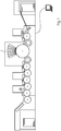
- FIG. 1 shows a printing machine with a plurality of print bars 1 for inkjet printing on substrate made of paper or cardboard.
- the substrate has the form of a bow, but could also be in the form of a web.
- the pressure bars 1 are identical, so that only one pressure bar 1 needs to be described.
- the pressure bar 1 has printheads 2 in a row perpendicular to the plane of the drawing FIG. 1 runs. The row of print heads 2 extends across the width of the format of the printing substrate and the printing bar 1 is used for page-wide printing.
- Each printhead 2 is associated with an adjustment device, with which the printhead 2 can be adjusted relative to its adjacent printheads 2.
- This adjustment movement of the print head 2 driven by the adjustment device can be translational or rotational.
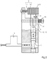
- the adjustment device in the Figures 2 and 3 comprises a holder 3, in which a screw 4 is screwed.
- the screw 4 has a cone 7, on which an intermediate piece of the print head 2 is applied.
- the screw 4 has a head 8, which serves as a handle or knob for tool-free turning of the screw 4.
- detent 9 which comprises a sprung pressure piece 11, for example a ball, and index recesses.
- the detent 9 is a multiple detent.
- the Pressure piece 11 occurs at each rotation step of the screw 4 in a different index recess.
- the screw 4 is thus very indexed depression index indexing rotated.
- the series of index depressions is introduced along the circumference of a locking disk, wherein the index depressions are uniformly distributed at a constant angular distance from each other.
- the locking disk is formed by the head 8 of the screw 4.
- the head 8 in a double function on the one hand forms the handle for rotating the screw 4 and on the other hand, the locking disc of the detent 9.
- the index recesses are formed as grooves 10 and are hereinafter referred to as such.
- the grooves 10 extend in the longitudinal direction parallel to the axis of rotation of the screw 4.
- Each groove 10 is longer than the maximum axial displacement of the screw 4 during adjustment.
- the path difference is compensated, resulting from the screwing of the screw 4 in the holder 3. Regardless of how deep the screw 4 is screwed into the holder 3, the pressure piece 11 is able to enter a groove 10.
- the grooves 10 are inserted into the head 8 and thus increase the grip of the knob formed by the head 8, which is advantageous.
- the clamping device comprises a clamping tongs or clamping bush 12, which is formed on the holder 3.
- a slot 13 is inserted into the holder 3, which runs parallel to the axis of rotation of the screws 4.
- a wall of the bore is interrupted, which is introduced into the holder 3 and the screw 4 receives.
- the slot 13 has an open end in the edge said wall opens.
- the slot 13 has a closed end in which the slot width is widened in a circular shape to form a kind of bending joint.
- a spring 14 loads the clamping bush 12 in radial direction with respect to the screw 4.
- the clamping bush 12 is compressed, with the two side walls of the slot 13 approach each other something.
- the internal thread 6 closes closer to the external thread 5, whereby the thread play is minimized.
- the spring 14 is supported with its one end on the clamping bush 12 and with its other end on a screw 15.
- This screw 15 is screwed transversely to the screw 4 in the holder 3.
- the spring 14 is a resilient to pressure coil spring and is seated on the shank of the screw 15. By turning the screw 15, the bias of the spring 14 can be adjusted.
- the clamping device is formed by a spring 16 which is supported with its one end on the head 8 of the screw 4 and with its other end on the holder 3.
- the spring 16 is a resilient to pressure coil spring and sits on the screw 4, which is inserted through the spring 16 therethrough.
- the spring 16 acts with respect to the screw 4 in the axial direction and strives to push the screw 4 out of the holder 3 out. Characterized the external thread 5 of the screw 4 is pressed against the internal thread 6 of the holder 3, whereby the thread play between them is minimized.
Landscapes
- Ink Jet (AREA)
- Common Mechanisms (AREA)
Abstract
Description
- Vorliegende Erfindung betrifft eine Vorrichtung zur Justage eines Druckkopfs, umfassend einen Halter, eine Schraube mit einem Konus, wobei die Schraube in den Halter eingeschraubt ist und der Druckkopf an dem Konus anliegt.
- Bei Druckbalken mit einer Reihe von Druckköpfen müssen die Druckköpfe zueinander justiert werden. Dazu dienen Justage-Vorrichtungen, die jeweils eine Schraube mit einem Konus aufweisen. An dem Konus liegt der jeweilige Druckkopf direkt oder über ein Zwischenstück indirekt an. Der Konus bildet ein Schubkeilgetriebe, das eine axiale Bewegung der Schraube in eine zu ihr radiale Bewegung des Druckkopfs umsetzt.
- In
US 2009/0147048 A1 ist eine solche Justage-Vorrichtung beschrieben. Deren Präzision wird durch das Gewindespiel, also das Spiel zwischen dem Außengewinde der Schraube und dem Innengewinde des Halters, beeinträchtigt.
Außerdem leidet die Präzision darunter, dass der Bediener beim Justieren ein Übersteuern oder Untersteuern nicht immer vermeiden kann, weil das Drehen der Schraube stufenlos erfolgt. - Aufgabe der Erfindung ist, eine Justage-Vorrichtung für einen Druckkopf zu schaffen, die präzise arbeitet.
- Die Aufgabe wird durch eine Vorrichtung zur Justage eines Druckkopfs gelöst, die einen Halter und eine Schraube mit einem Konus umfasst, wobei die Schraube in den Halter eingeschraubt ist und der Druckkopf an dem Konus anliegt. Die erfindungsgemäße Vorrichtung ist dadurch gekennzeichnet, dass eine Feder vorhanden ist, um ein Gewindespiel zwischen dem Halter und der Schraube zu verringern, und dass eine Rastung vorhanden ist, um eine Schrittweite beim Drehen der Schraube zu bestimmen.
- Die erfindungsgemäße Vorrichtung arbeitet hochpräzise, weil durch die Feder das Spiel zwischen dem Außengewinde der Schraube und dem Innengewinde des Halters kompensiert wird.
- Ein Zusatzvorteil der Feder ist ihre Wirkung als Sicherung der Schraube gegen ein unbeabsichtigtes Verdrehen. Durch die Feder wird die Gewindereibung erhöht und dadurch die Schraube gebremst, so dass sie sich nicht selbsttätig verdrehen kann.
- Überraschenderweise ist durch das stufen- bzw. schrittweise Drehen der Schraube, welches durch die Rastung ermöglicht wird, eine präzisere Justage als durch das stufenlose Drehen der Schraube beim Stand der Technik möglich. Die Rastung bewirkt bei manueller Bedienung, dass mit jedem Rastschritt eine sehr präzise Einstellbewegung mit haptischer Rückmeldung übertragen werden kann. Dadurch wird ein Übersteuern und Untersteuern sicher vermieden.
- In manchen Anwendungsfällen kann nur eine der beiden technischen Maßnahmen - die Feder und die Rastung - allein ausreichend sein, um die notwendige Präzision der Justage zu gewährleisten.
- Es sind verschiedene Weiterbildungen möglich:
- Ein Kopf der Schraube kann eine Rastscheibe der Rastung bilden.
- Die Rastung kann Nuten aufweisen, die mit der Schraube achsparallel verlaufen.
- Die Feder kann so angeordnet sein, dass sie bezüglich der Schraube axial wirkt.
- Dazu kann die Feder auf die Schraube gesteckt sein.
- Bei einer weiteren Weiterbildung ist die Feder so angeordnet, dass sie bezüglich der Schraube radial wirkt.
- Dazu kann der Halter eine Klemmbuchse aufweisen, die durch die Feder belastet ist.
- Weiterbildungen ergeben sich auch aus der nachfolgenden Beschreibung von Ausführungsbeispielen und der zugehörigen Zeichnung, in welcher zeigt:
- Figur 1:
- eine Druckmaschine mit einem Druckbalken für Inkjet,
- Figur 2:
- einen Druckkopf des Druckbalkens und ein erste Ausführungsbeispiel einer Justage-Vorrichtung für den Druckkopf und
- Figur 3:
- den Druckkopf und ein zweites Ausführungsbeispiel für die Justage-Vorrichtung.
-
Figur 1 zeigt eine Druckmaschine mit mehreren Druckbalken 1 für Tintenstrahldruck auf Bedruckstoff aus Papier oder Karton. Der Bedruckstoff hat die Form von Bogen, könnte aber auch die Form einer Bahn haben. Die Druckbalken 1 sind baugleich, so dass nur ein Druckbalken 1 beschrieben werden braucht. Der Druckbalken 1 weist Druckköpfe 2 in einer Reihe auf, die senkrecht zur Zeichnungsebene vonFigur 1 verläuft. Die Reihe von Druckköpfen 2 erstreckt sich über die Breite des Formats des Bedruckstoffs und der Druckbalken 1 dient zum seitenbreiten Druck. - Jedem Druckkopf 2 ist eine Justage-Vorrichtung beigeordnet, mit welcher der Druckkopf 2 relativ zu seinen benachbarten Druckköpfen 2 verstellt werden kann. Diese von der Justage-Vorrichtung angetriebene Verstellbewegung des Druckkopfs 2 kann translativ oder rotativ sein.
- Die in den
Figuren 2 und3 gezeigten Ausführungsbeispiele der Justage-Vorrichtung weisen Gemeinsamkeiten auf, welche zuerst beschrieben werden. Für in denFiguren 2 und3 einander entsprechende Bauteile werden die gleichen Bezugszeichen verwendet. - Die Justage-Vorrichtung in den
Figuren 2 und3 umfasst einen Halter 3, in den eine Schraube 4 eingeschraubt ist. Die Schraube 4 hat einen Konus 7, an welchem über ein Zwischenstück der Druckkopf 2 anliegt. Die Schraube 4 hat einen Kopf 8, welcher als Griff oder Drehknauf zum werkzeuglosen Drehen der Schraube 4 dient. - Es ist eine Rastung 9 vorhanden, welche ein gefedertes Druckstück 11, z.B. eine Kugel, und Index-Vertiefungen umfasst. Die Rastung 9 ist eine Mehrfach-Rastung. Das Druckstück 11 tritt bei jedem Drehschritt der Schraube 4 in eine andere Index-Vertiefung ein. Die Schraube 4 wird somit Index-Vertiefung für Index-Vertiefung sehr kontrolliert gedreht. Die Reihe von Index-Vertiefungen ist entlang des Umfangs einer Rastscheibe eingebracht, wobei die Index-Vertiefungen im konstantem Winkelabstand zueinander gleichmäßig verteilt sind. Die Rastscheibe wird durch den Kopf 8 der Schraube 4 gebildet.
- Vorteilhaft ist, dass der Kopf 8 in Doppelfunktion einerseits den Griff zum Drehen der Schraube 4 und andererseits die Rastscheibe der Rastung 9 bildet.
- Die Index-Vertiefungen sind als Nuten 10 ausgebildet und werden nachfolgend als solche bezeichnet. Die Nuten 10 verlaufen in Längsrichtung parallel mit der Rotationsachse der Schraube 4. Jede Nut 10 ist länger als der maximale axiale Verstellweg der Schraube 4 beim Justieren. Durch die Nutlänge wird die Wegdifferenz kompensiert, die aus dem Einschrauben der Schraube 4 in den Halter 3 resultiert. Unabhängig davon, wie tief die Schraube 4 in den Halter 3 eingeschraubt wird, vermag das Druckstück 11 in eine Nut 10 einzutreten.
- Die Nuten 10 sind in den Kopf 8 eingebracht und erhöhen somit die Griffigkeit des durch den Kopf 8 gebildeten Drehknaufs, was vorteilhaft ist.
- Zwischen einem Außengewinde 5 der Schraube 4 und einem Innengewinde 6 des Halters 3, in welches das Außengewinde 5 eingeschraubt ist, ist ein gewisses Gewindespiel vorhanden. Um dieses Gewindespiel zu minimieren, ist eine Klemmeinrichtung vorhanden, die bei den beiden Ausführungsbeispielen unterschiedlich ist, weshalb nachfolgend die
Figuren 2 und3 getrennt voneinander weiterbeschrieben werden. - Bei dem Ausführungsbeispiel in
Figur 2 umfasst die Klemmeinrichtung eine Klemmzange oder Klemmbuchse 12, die an dem Halter 3 ausgebildet ist. Dazu ist in den Halter 3 ein Schlitz 13 eingebracht, der mit der Rotationsachse der Schrauben 4 parallel verläuft. Durch den Schlitz 13 wird eine Wand der Bohrung unterbrochen, die in den Halter 3 eingebracht ist und die Schraube 4 aufnimmt. Der Schlitz 13 hat ein offenes Ende, das im Rand besagter Wand mündet. Außerdem hat der Schlitz 13 ein geschlossenes Ende, bei dem die Schlitzbreite in Kreisform erweitert ist, um eine Art Biegegelenk zu bilden. - Eine Feder 14 belastet die Klemmbuchse 12 in bezüglich der Schraube 4 radialer Richtung. Durch die Feder 14 wird die Klemmbuchse 12 zusammengedrückt, wobei sich die beiden Seitenwände des Schlitzes 13 einander etwas nähern. Infolgedessen schließt sich das Innengewinde 6 enger um das Außengewinde 5, wodurch das Gewindespiel minimiert wird. Die Feder 14 stützt sich mit ihrem einen Ende auf der Klemmbuchse 12 und mit ihrem anderen Ende auf einer Schraube 15 ab. Diese Schraube 15 ist quer zur Schraube 4 in den Halter 3 eingeschraubt. Die Feder 14 ist eine auf Druck belastbare Schraubenfeder und sitzt auf dem Schaft der Schraube 15. Durch ein Verdrehen der Schraube 15 lässt sich die Vorspannung der Feder 14 einstellen.
- Bei dem Ausführungsbeispiel in
Figur 3 wird die Klemmeinrichtung durch eine Feder 16 gebildet, welche mit ihrem einen Ende auf dem Kopf 8 der Schraube 4 und mit ihrem anderen Ende auf dem Halter 3 abgestützt ist. Die Feder 16 ist eine auf Druck belastbare Schraubenfeder und sitzt auf der Schraube 4, welche durch die Feder 16 hindurch gesteckt ist. Die Feder 16 wirkt bezüglich der Schraube 4 in axialer Richtung und ist bestrebt, die Schraube 4 aus dem Halter 3 heraus zu schieben. Dadurch wird das Außengewinde 5 der Schraube 4 gegen das Innengewinde 6 des Halters 3 gepresst, wodurch das Gewindespiel zwischen beiden minimiert wird. - Der Vorteil des Ausführungsbeispiels nach
Figur 2 gegenüber jenem nachFigur 3 ist, dass bei dem Ausführungsbeispiel inFigur 2 die von der Feder 14 erzeugte Klemmkraft bei jeder Einschraubtiefe der Schraube 4 gleich groß ist. - Der Vorteil des Ausführungsbeispiels nach
Figur 3 gegenüber jenem nachFigur 2 ist, dass bei dem Ausführungsbeispiel inFigur 3 für die Lagerung der Feder 16 weniger Bauteile erforderlich sind, weil dazu der ohnehin vorhandene Schaft der Schraube 4 genutzt wird. -
- 1
- Druckbalken
- 2
- Druckkopf
- 3
- Halter
- 4
- Schraube
- 5
- Außengewinde
- 6
- Innengewinde
- 7
- Konus
- 8
- Kopf
- 9
- Rastung
- 10
- Nut
- 11
- Druckstück
- 12
- Klemmbuchse
- 13
- Schlitz
- 14
- Feder
- 15
- Schraube
- 16
- Feder
Claims (7)
- Vorrichtung zur Justage eines Druckkopfs (2), umfassend einen Halter (3), eine Schraube (4) mit einem Konus (7), wobei die Schraube (4) in den Halter (3) eingeschraubt ist und der Druckkopf (2) an dem Konus (7) anliegt,
dadurch gekennzeichnet,
dass eine Feder (14, 16) vorhanden ist, um ein Gewindespiel zwischen dem Halter (3) und der Schraube (4) zu verringern, und dass eine Rastung (9) vorhanden ist, um eine Schrittweite beim Drehen der Schraube (4) zu bestimmen. - Vorrichtung nach Anspruch 1,
dadurch gekennzeichnet,
dass ein Kopf (8) der Schraube (4) eine Rastscheibe der Rastung (9) bildet. - Vorrichtung nach Anspruch 1 oder 2,
dadurch gekennzeichnet,
dass die Rastung (9) Nuten (10) aufweist, die mit der Schraube (4) achsparallel verlaufen. - Vorrichtung nach einem der Ansprüche 1 bis 3,
dadurch gekennzeichnet,
dass die Feder (16) bezüglich der Schraube (4) axial wirkt. - Vorrichtung nach Anspruch 4,
dadurch gekennzeichnet,
dass die Feder (16) auf die Schraube (4) gesteckt ist. - Vorrichtung nach einem der Ansprüche 1 bis 3,
dadurch gekennzeichnet,
dass die Feder (14) bezüglich der Schraube (4) radial wirkt. - Vorrichtung nach Anspruch 6,
dadurch gekennzeichnet,
dass der Halter 3 eine Klemmbuchse (12) aufweist, die durch die Feder (14) belastet ist.
Priority Applications (3)
| Application Number | Priority Date | Filing Date | Title |
|---|---|---|---|
| EP18156645.6A EP3527390B1 (de) | 2018-02-14 | 2018-02-14 | Vorrichtung zur justage eines druckkopfs |
| CN201910112406.1A CN110154529B (zh) | 2018-02-14 | 2019-02-13 | 用于校准印刷头的设备 |
| JP2019000496U JP3221875U (ja) | 2018-02-14 | 2019-02-14 | 印刷ヘッドを調整する装置 |
Applications Claiming Priority (1)
| Application Number | Priority Date | Filing Date | Title |
|---|---|---|---|
| EP18156645.6A EP3527390B1 (de) | 2018-02-14 | 2018-02-14 | Vorrichtung zur justage eines druckkopfs |
Publications (2)
| Publication Number | Publication Date |
|---|---|
| EP3527390A1 true EP3527390A1 (de) | 2019-08-21 |
| EP3527390B1 EP3527390B1 (de) | 2020-02-19 |
Family
ID=61223797
Family Applications (1)
| Application Number | Title | Priority Date | Filing Date |
|---|---|---|---|
| EP18156645.6A Active EP3527390B1 (de) | 2018-02-14 | 2018-02-14 | Vorrichtung zur justage eines druckkopfs |
Country Status (3)
| Country | Link |
|---|---|
| EP (1) | EP3527390B1 (de) |
| JP (1) | JP3221875U (de) |
| CN (1) | CN110154529B (de) |
Cited By (1)
| Publication number | Priority date | Publication date | Assignee | Title |
|---|---|---|---|---|
| CN110293774A (zh) * | 2019-07-26 | 2019-10-01 | 河南奥德利数码科技有限公司 | 一种打印机喷头调节结构 |
Families Citing this family (3)
| Publication number | Priority date | Publication date | Assignee | Title |
|---|---|---|---|---|
| JP7435108B2 (ja) * | 2020-03-19 | 2024-02-21 | 京セラドキュメントソリューションズ株式会社 | インクジェット記録装置 |
| DE102024104484A1 (de) | 2023-03-23 | 2024-09-26 | Heidelberger Druckmaschinen Aktiengesellschaft | Druckwerk einer Tintendruckmaschine |
| DE102023107319B3 (de) | 2023-03-23 | 2024-02-15 | Heidelberger Druckmaschinen Aktiengesellschaft | Vorrichtung zur Justage eines Druckkopfes |
Citations (3)
| Publication number | Priority date | Publication date | Assignee | Title |
|---|---|---|---|---|
| US20090147048A1 (en) | 2007-12-10 | 2009-06-11 | Yong Zhao | Tuning apparatus for a printhead |
| DE102010060412A1 (de) * | 2010-11-08 | 2012-05-10 | OCé PRINTING SYSTEMS GMBH | Vorrichtung zur mechanischen Einstellung eines Druckkopfes bei einem Tintendruckgerät |
| EP2979881A1 (de) * | 2014-07-30 | 2016-02-03 | Inca Digital Printers Limited | Druckkopfbefestigungssystem |
Family Cites Families (8)
| Publication number | Priority date | Publication date | Assignee | Title |
|---|---|---|---|---|
| US5428375A (en) * | 1992-05-29 | 1995-06-27 | Simon; Robert J. | Multiple print head ink jet printer |
| DE19581389T1 (de) * | 1994-10-06 | 1996-12-05 | Pfu Ltd | Verfahren und Vorrichtung zur Papierzuführung für einen Drucker |
| US5870117A (en) * | 1997-01-21 | 1999-02-09 | Xerox Corporation | Liquid ink printer including a camming printhead to enable increased resolution printing |
| JPH10235965A (ja) * | 1997-02-28 | 1998-09-08 | Tec Corp | インクジェットプリンタ |
| US6554398B2 (en) * | 2001-03-08 | 2003-04-29 | Agfa-Gevaert | Ink-jet printer equipped for aligning the printheads |
| US7270387B2 (en) * | 2004-01-30 | 2007-09-18 | Konica Minolta Holdings Inc. | Recording head position adjusting structure and inkjet printer provided with said adjusting structure |
| KR100863244B1 (ko) * | 2004-10-07 | 2008-10-15 | 삼성전자주식회사 | 잉크젯 헤드 마운트 및 이를 구비하는 잉크젯 프린트 장치. |
| ES2370632B1 (es) * | 2010-02-09 | 2012-11-06 | Tkt Brainpower S.L. | Sistema de ajuste de la base del cabezal de impresión de una máquina trazadora. |
-
2018
- 2018-02-14 EP EP18156645.6A patent/EP3527390B1/de active Active
-
2019
- 2019-02-13 CN CN201910112406.1A patent/CN110154529B/zh active Active
- 2019-02-14 JP JP2019000496U patent/JP3221875U/ja active Active
Patent Citations (3)
| Publication number | Priority date | Publication date | Assignee | Title |
|---|---|---|---|---|
| US20090147048A1 (en) | 2007-12-10 | 2009-06-11 | Yong Zhao | Tuning apparatus for a printhead |
| DE102010060412A1 (de) * | 2010-11-08 | 2012-05-10 | OCé PRINTING SYSTEMS GMBH | Vorrichtung zur mechanischen Einstellung eines Druckkopfes bei einem Tintendruckgerät |
| EP2979881A1 (de) * | 2014-07-30 | 2016-02-03 | Inca Digital Printers Limited | Druckkopfbefestigungssystem |
Cited By (1)
| Publication number | Priority date | Publication date | Assignee | Title |
|---|---|---|---|---|
| CN110293774A (zh) * | 2019-07-26 | 2019-10-01 | 河南奥德利数码科技有限公司 | 一种打印机喷头调节结构 |
Also Published As
| Publication number | Publication date |
|---|---|
| CN110154529B (zh) | 2020-11-03 |
| JP3221875U (ja) | 2019-06-27 |
| CN110154529A (zh) | 2019-08-23 |
| EP3527390B1 (de) | 2020-02-19 |
Similar Documents
| Publication | Publication Date | Title |
|---|---|---|
| EP0312951B1 (de) | Spannvorrichtung | |
| EP3527390B1 (de) | Vorrichtung zur justage eines druckkopfs | |
| DE69522201T2 (de) | Werkzeughalter | |
| EP2288459B1 (de) | Werkzeugkassette | |
| EP0273259A1 (de) | Spannvorrichtung für insbesondere zahnärztliche Werkzeuge | |
| DE102018106558B4 (de) | Von vorn geladener, seitlich aktivierter, modularer bohrer und schneideinsatz | |
| DE112017006304B4 (de) | Seitlich aktivierter modularer bohrer | |
| DE102008040561A1 (de) | Ausbohrwerkzeug | |
| DE202011050277U1 (de) | Bohrwerkzeug | |
| EP3004664B1 (de) | Schraube mit einem einen antrieb aufweisenden schraubenkopf | |
| DE102008040563A1 (de) | Werkzeug mit Befestigungseinrichtung | |
| EP1640095B1 (de) | Fräswerkzeug, insbesondere Gewindefräser | |
| DE102019116160A1 (de) | Seitlich geschlossener modularer Bohrer mit federunterstütztem Auswurf | |
| DE102015122385A1 (de) | Nockenbolzen und werkzeug-kupplungssystem für solche | |
| EP1858670A1 (de) | Drehmomentübertragungseinrichtung mit klemmsitz zwischen antriebs- und abtriebsteil, insbesondere schraubwerkzeug | |
| DE102017131001A1 (de) | Fräswerkzeug-Halter und Fräswerkzeug | |
| EP3234389B1 (de) | Kupplungselement und kupplungsanordnung zur axialen drehmomentübertragung, und lamellenanordnung für solche | |
| WO2014041130A1 (de) | Werkzeug zur spanenden bearbeitung von werkstücken | |
| DE102013208163A1 (de) | Adapter für eine Ausgangswelle eines Getriebes | |
| DE102011101935B4 (de) | Werkzeughalter mit axialem Ausweichmechanismus und Verfahren zur Herstellung eines Werkzeughalters mit einem Ausweichmechanismus | |
| EP3292931B1 (de) | Werkzeug, insbesondere für die spanabhebende werkstückbearbeitung | |
| WO2019020786A1 (de) | Zerspanungswerkzeug | |
| DE202010000541U1 (de) | Anordnung zur unidirektionalen Stabilisierung des Eingangsluftdrucks eines pneumatischen Werkzeugs | |
| DE2116818C3 (de) | Schraubenzieher | |
| AT516434B1 (de) | Endbearbeitungsaggregat mit lageverstellbarer Kopiereinrichtung |
Legal Events
| Date | Code | Title | Description |
|---|---|---|---|
| PUAI | Public reference made under article 153(3) epc to a published international application that has entered the european phase |
Free format text: ORIGINAL CODE: 0009012 |
|
| STAA | Information on the status of an ep patent application or granted ep patent |
Free format text: STATUS: REQUEST FOR EXAMINATION WAS MADE |
|
| 17P | Request for examination filed |
Effective date: 20181116 |
|
| AK | Designated contracting states |
Kind code of ref document: A1 Designated state(s): AL AT BE BG CH CY CZ DE DK EE ES FI FR GB GR HR HU IE IS IT LI LT LU LV MC MK MT NL NO PL PT RO RS SE SI SK SM TR |
|
| AX | Request for extension of the european patent |
Extension state: BA ME |
|
| GRAP | Despatch of communication of intention to grant a patent |
Free format text: ORIGINAL CODE: EPIDOSNIGR1 |
|
| STAA | Information on the status of an ep patent application or granted ep patent |
Free format text: STATUS: GRANT OF PATENT IS INTENDED |
|
| INTG | Intention to grant announced |
Effective date: 20190925 |
|
| GRAS | Grant fee paid |
Free format text: ORIGINAL CODE: EPIDOSNIGR3 |
|
| GRAA | (expected) grant |
Free format text: ORIGINAL CODE: 0009210 |
|
| STAA | Information on the status of an ep patent application or granted ep patent |
Free format text: STATUS: THE PATENT HAS BEEN GRANTED |
|
| AK | Designated contracting states |
Kind code of ref document: B1 Designated state(s): AL AT BE BG CH CY CZ DE DK EE ES FI FR GB GR HR HU IE IS IT LI LT LU LV MC MK MT NL NO PL PT RO RS SE SI SK SM TR |
|
| REG | Reference to a national code |
Ref country code: CH Ref legal event code: EP |
|
| REG | Reference to a national code |
Ref country code: DE Ref legal event code: R096 Ref document number: 502018000773 Country of ref document: DE |
|
| REG | Reference to a national code |
Ref country code: AT Ref legal event code: REF Ref document number: 1234501 Country of ref document: AT Kind code of ref document: T Effective date: 20200315 |
|
| REG | Reference to a national code |
Ref country code: IE Ref legal event code: FG4D Free format text: LANGUAGE OF EP DOCUMENT: GERMAN |
|
| REG | Reference to a national code |
Ref country code: NL Ref legal event code: MP Effective date: 20200219 |
|
| PG25 | Lapsed in a contracting state [announced via postgrant information from national office to epo] |
Ref country code: NO Free format text: LAPSE BECAUSE OF FAILURE TO SUBMIT A TRANSLATION OF THE DESCRIPTION OR TO PAY THE FEE WITHIN THE PRESCRIBED TIME-LIMIT Effective date: 20200519 Ref country code: RS Free format text: LAPSE BECAUSE OF FAILURE TO SUBMIT A TRANSLATION OF THE DESCRIPTION OR TO PAY THE FEE WITHIN THE PRESCRIBED TIME-LIMIT Effective date: 20200219 Ref country code: FI Free format text: LAPSE BECAUSE OF FAILURE TO SUBMIT A TRANSLATION OF THE DESCRIPTION OR TO PAY THE FEE WITHIN THE PRESCRIBED TIME-LIMIT Effective date: 20200219 |
|
| REG | Reference to a national code |
Ref country code: LT Ref legal event code: MG4D |
|
| PG25 | Lapsed in a contracting state [announced via postgrant information from national office to epo] |
Ref country code: LV Free format text: LAPSE BECAUSE OF FAILURE TO SUBMIT A TRANSLATION OF THE DESCRIPTION OR TO PAY THE FEE WITHIN THE PRESCRIBED TIME-LIMIT Effective date: 20200219 Ref country code: SE Free format text: LAPSE BECAUSE OF FAILURE TO SUBMIT A TRANSLATION OF THE DESCRIPTION OR TO PAY THE FEE WITHIN THE PRESCRIBED TIME-LIMIT Effective date: 20200219 Ref country code: IS Free format text: LAPSE BECAUSE OF FAILURE TO SUBMIT A TRANSLATION OF THE DESCRIPTION OR TO PAY THE FEE WITHIN THE PRESCRIBED TIME-LIMIT Effective date: 20200619 Ref country code: HR Free format text: LAPSE BECAUSE OF FAILURE TO SUBMIT A TRANSLATION OF THE DESCRIPTION OR TO PAY THE FEE WITHIN THE PRESCRIBED TIME-LIMIT Effective date: 20200219 Ref country code: GR Free format text: LAPSE BECAUSE OF FAILURE TO SUBMIT A TRANSLATION OF THE DESCRIPTION OR TO PAY THE FEE WITHIN THE PRESCRIBED TIME-LIMIT Effective date: 20200520 Ref country code: BG Free format text: LAPSE BECAUSE OF FAILURE TO SUBMIT A TRANSLATION OF THE DESCRIPTION OR TO PAY THE FEE WITHIN THE PRESCRIBED TIME-LIMIT Effective date: 20200519 |
|
| PG25 | Lapsed in a contracting state [announced via postgrant information from national office to epo] |
Ref country code: NL Free format text: LAPSE BECAUSE OF FAILURE TO SUBMIT A TRANSLATION OF THE DESCRIPTION OR TO PAY THE FEE WITHIN THE PRESCRIBED TIME-LIMIT Effective date: 20200219 |
|
| PG25 | Lapsed in a contracting state [announced via postgrant information from national office to epo] |
Ref country code: LT Free format text: LAPSE BECAUSE OF FAILURE TO SUBMIT A TRANSLATION OF THE DESCRIPTION OR TO PAY THE FEE WITHIN THE PRESCRIBED TIME-LIMIT Effective date: 20200219 Ref country code: CZ Free format text: LAPSE BECAUSE OF FAILURE TO SUBMIT A TRANSLATION OF THE DESCRIPTION OR TO PAY THE FEE WITHIN THE PRESCRIBED TIME-LIMIT Effective date: 20200219 Ref country code: SK Free format text: LAPSE BECAUSE OF FAILURE TO SUBMIT A TRANSLATION OF THE DESCRIPTION OR TO PAY THE FEE WITHIN THE PRESCRIBED TIME-LIMIT Effective date: 20200219 Ref country code: RO Free format text: LAPSE BECAUSE OF FAILURE TO SUBMIT A TRANSLATION OF THE DESCRIPTION OR TO PAY THE FEE WITHIN THE PRESCRIBED TIME-LIMIT Effective date: 20200219 Ref country code: SM Free format text: LAPSE BECAUSE OF FAILURE TO SUBMIT A TRANSLATION OF THE DESCRIPTION OR TO PAY THE FEE WITHIN THE PRESCRIBED TIME-LIMIT Effective date: 20200219 Ref country code: DK Free format text: LAPSE BECAUSE OF FAILURE TO SUBMIT A TRANSLATION OF THE DESCRIPTION OR TO PAY THE FEE WITHIN THE PRESCRIBED TIME-LIMIT Effective date: 20200219 Ref country code: PT Free format text: LAPSE BECAUSE OF FAILURE TO SUBMIT A TRANSLATION OF THE DESCRIPTION OR TO PAY THE FEE WITHIN THE PRESCRIBED TIME-LIMIT Effective date: 20200712 Ref country code: EE Free format text: LAPSE BECAUSE OF FAILURE TO SUBMIT A TRANSLATION OF THE DESCRIPTION OR TO PAY THE FEE WITHIN THE PRESCRIBED TIME-LIMIT Effective date: 20200219 Ref country code: ES Free format text: LAPSE BECAUSE OF FAILURE TO SUBMIT A TRANSLATION OF THE DESCRIPTION OR TO PAY THE FEE WITHIN THE PRESCRIBED TIME-LIMIT Effective date: 20200219 |
|
| REG | Reference to a national code |
Ref country code: DE Ref legal event code: R097 Ref document number: 502018000773 Country of ref document: DE |
|
| PLBE | No opposition filed within time limit |
Free format text: ORIGINAL CODE: 0009261 |
|
| STAA | Information on the status of an ep patent application or granted ep patent |
Free format text: STATUS: NO OPPOSITION FILED WITHIN TIME LIMIT |
|
| 26N | No opposition filed |
Effective date: 20201120 |
|
| PG25 | Lapsed in a contracting state [announced via postgrant information from national office to epo] |
Ref country code: IT Free format text: LAPSE BECAUSE OF FAILURE TO SUBMIT A TRANSLATION OF THE DESCRIPTION OR TO PAY THE FEE WITHIN THE PRESCRIBED TIME-LIMIT Effective date: 20200219 |
|
| PG25 | Lapsed in a contracting state [announced via postgrant information from national office to epo] |
Ref country code: PL Free format text: LAPSE BECAUSE OF FAILURE TO SUBMIT A TRANSLATION OF THE DESCRIPTION OR TO PAY THE FEE WITHIN THE PRESCRIBED TIME-LIMIT Effective date: 20200219 |
|
| PG25 | Lapsed in a contracting state [announced via postgrant information from national office to epo] |
Ref country code: MC Free format text: LAPSE BECAUSE OF FAILURE TO SUBMIT A TRANSLATION OF THE DESCRIPTION OR TO PAY THE FEE WITHIN THE PRESCRIBED TIME-LIMIT Effective date: 20200219 |
|
| REG | Reference to a national code |
Ref country code: BE Ref legal event code: MM Effective date: 20210228 |
|
| PG25 | Lapsed in a contracting state [announced via postgrant information from national office to epo] |
Ref country code: LU Free format text: LAPSE BECAUSE OF NON-PAYMENT OF DUE FEES Effective date: 20210214 Ref country code: LI Free format text: LAPSE BECAUSE OF NON-PAYMENT OF DUE FEES Effective date: 20210228 Ref country code: CH Free format text: LAPSE BECAUSE OF NON-PAYMENT OF DUE FEES Effective date: 20210228 |
|
| PG25 | Lapsed in a contracting state [announced via postgrant information from national office to epo] |
Ref country code: FR Free format text: LAPSE BECAUSE OF NON-PAYMENT OF DUE FEES Effective date: 20210228 Ref country code: IE Free format text: LAPSE BECAUSE OF NON-PAYMENT OF DUE FEES Effective date: 20210214 |
|
| PG25 | Lapsed in a contracting state [announced via postgrant information from national office to epo] |
Ref country code: BE Free format text: LAPSE BECAUSE OF NON-PAYMENT OF DUE FEES Effective date: 20210228 |
|
| GBPC | Gb: european patent ceased through non-payment of renewal fee |
Effective date: 20220214 |
|
| PG25 | Lapsed in a contracting state [announced via postgrant information from national office to epo] |
Ref country code: GB Free format text: LAPSE BECAUSE OF NON-PAYMENT OF DUE FEES Effective date: 20220214 |
|
| P01 | Opt-out of the competence of the unified patent court (upc) registered |
Effective date: 20230502 |
|
| PG25 | Lapsed in a contracting state [announced via postgrant information from national office to epo] |
Ref country code: CY Free format text: LAPSE BECAUSE OF FAILURE TO SUBMIT A TRANSLATION OF THE DESCRIPTION OR TO PAY THE FEE WITHIN THE PRESCRIBED TIME-LIMIT Effective date: 20200219 |
|
| PG25 | Lapsed in a contracting state [announced via postgrant information from national office to epo] |
Ref country code: HU Free format text: LAPSE BECAUSE OF FAILURE TO SUBMIT A TRANSLATION OF THE DESCRIPTION OR TO PAY THE FEE WITHIN THE PRESCRIBED TIME-LIMIT; INVALID AB INITIO Effective date: 20180214 |
|
| PG25 | Lapsed in a contracting state [announced via postgrant information from national office to epo] |
Ref country code: SI Free format text: LAPSE BECAUSE OF FAILURE TO SUBMIT A TRANSLATION OF THE DESCRIPTION OR TO PAY THE FEE WITHIN THE PRESCRIBED TIME-LIMIT Effective date: 20200219 |
|
| REG | Reference to a national code |
Ref country code: AT Ref legal event code: MM01 Ref document number: 1234501 Country of ref document: AT Kind code of ref document: T Effective date: 20230214 |
|
| PG25 | Lapsed in a contracting state [announced via postgrant information from national office to epo] |
Ref country code: AT Free format text: LAPSE BECAUSE OF NON-PAYMENT OF DUE FEES Effective date: 20230214 |
|
| PG25 | Lapsed in a contracting state [announced via postgrant information from national office to epo] |
Ref country code: MK Free format text: LAPSE BECAUSE OF FAILURE TO SUBMIT A TRANSLATION OF THE DESCRIPTION OR TO PAY THE FEE WITHIN THE PRESCRIBED TIME-LIMIT Effective date: 20200219 Ref country code: AT Free format text: LAPSE BECAUSE OF NON-PAYMENT OF DUE FEES Effective date: 20230214 |
|
| PG25 | Lapsed in a contracting state [announced via postgrant information from national office to epo] |
Ref country code: TR Free format text: LAPSE BECAUSE OF FAILURE TO SUBMIT A TRANSLATION OF THE DESCRIPTION OR TO PAY THE FEE WITHIN THE PRESCRIBED TIME-LIMIT Effective date: 20200219 |
|
| PG25 | Lapsed in a contracting state [announced via postgrant information from national office to epo] |
Ref country code: MT Free format text: LAPSE BECAUSE OF FAILURE TO SUBMIT A TRANSLATION OF THE DESCRIPTION OR TO PAY THE FEE WITHIN THE PRESCRIBED TIME-LIMIT Effective date: 20200219 |
|
| PGFP | Annual fee paid to national office [announced via postgrant information from national office to epo] |
Ref country code: DE Payment date: 20260228 Year of fee payment: 9 |
|
| PGFP | Annual fee paid to national office [announced via postgrant information from national office to epo] |
Ref country code: AT Payment date: 20260410 Year of fee payment: 5 |