EP3527354B1 - Machine for welding a medical bag made of a plastic material - Google Patents
Machine for welding a medical bag made of a plastic material Download PDFInfo
- Publication number
- EP3527354B1 EP3527354B1 EP19157305.4A EP19157305A EP3527354B1 EP 3527354 B1 EP3527354 B1 EP 3527354B1 EP 19157305 A EP19157305 A EP 19157305A EP 3527354 B1 EP3527354 B1 EP 3527354B1
- Authority
- EP
- European Patent Office
- Prior art keywords
- welding
- machine
- circuit
- tubes
- medical bag
- Prior art date
- Legal status (The legal status is an assumption and is not a legal conclusion. Google has not performed a legal analysis and makes no representation as to the accuracy of the status listed.)
- Active
Links
Images

Classifications
-
- B—PERFORMING OPERATIONS; TRANSPORTING
- B29—WORKING OF PLASTICS; WORKING OF SUBSTANCES IN A PLASTIC STATE IN GENERAL
- B29C—SHAPING OR JOINING OF PLASTICS; SHAPING OF MATERIAL IN A PLASTIC STATE, NOT OTHERWISE PROVIDED FOR; AFTER-TREATMENT OF THE SHAPED PRODUCTS, e.g. REPAIRING
- B29C65/00—Joining or sealing of preformed parts, e.g. welding of plastics materials; Apparatus therefor
- B29C65/02—Joining or sealing of preformed parts, e.g. welding of plastics materials; Apparatus therefor by heating, with or without pressure
- B29C65/04—Dielectric heating, e.g. high-frequency welding, i.e. radio frequency welding of plastic materials having dielectric properties, e.g. PVC
-
- B—PERFORMING OPERATIONS; TRANSPORTING
- B29—WORKING OF PLASTICS; WORKING OF SUBSTANCES IN A PLASTIC STATE IN GENERAL
- B29C—SHAPING OR JOINING OF PLASTICS; SHAPING OF MATERIAL IN A PLASTIC STATE, NOT OTHERWISE PROVIDED FOR; AFTER-TREATMENT OF THE SHAPED PRODUCTS, e.g. REPAIRING
- B29C65/00—Joining or sealing of preformed parts, e.g. welding of plastics materials; Apparatus therefor
- B29C65/78—Means for handling the parts to be joined, e.g. for making containers or hollow articles, e.g. means for handling sheets, plates, web-like materials, tubular articles, hollow articles or elements to be joined therewith; Means for discharging the joined articles from the joining apparatus
- B29C65/7858—Means for handling the parts to be joined, e.g. for making containers or hollow articles, e.g. means for handling sheets, plates, web-like materials, tubular articles, hollow articles or elements to be joined therewith; Means for discharging the joined articles from the joining apparatus characterised by the feeding movement of the parts to be joined
- B29C65/7879—Means for handling the parts to be joined, e.g. for making containers or hollow articles, e.g. means for handling sheets, plates, web-like materials, tubular articles, hollow articles or elements to be joined therewith; Means for discharging the joined articles from the joining apparatus characterised by the feeding movement of the parts to be joined said parts to be joined moving in a closed path, e.g. a rectangular path
- B29C65/7882—Means for handling the parts to be joined, e.g. for making containers or hollow articles, e.g. means for handling sheets, plates, web-like materials, tubular articles, hollow articles or elements to be joined therewith; Means for discharging the joined articles from the joining apparatus characterised by the feeding movement of the parts to be joined said parts to be joined moving in a closed path, e.g. a rectangular path said parts to be joined moving in a circular path
-
- B—PERFORMING OPERATIONS; TRANSPORTING
- B29—WORKING OF PLASTICS; WORKING OF SUBSTANCES IN A PLASTIC STATE IN GENERAL
- B29C—SHAPING OR JOINING OF PLASTICS; SHAPING OF MATERIAL IN A PLASTIC STATE, NOT OTHERWISE PROVIDED FOR; AFTER-TREATMENT OF THE SHAPED PRODUCTS, e.g. REPAIRING
- B29C66/00—General aspects of processes or apparatus for joining preformed parts
- B29C66/01—General aspects dealing with the joint area or with the area to be joined
- B29C66/05—Particular design of joint configurations
- B29C66/10—Particular design of joint configurations particular design of the joint cross-sections
- B29C66/11—Joint cross-sections comprising a single joint-segment, i.e. one of the parts to be joined comprising a single joint-segment in the joint cross-section
- B29C66/112—Single lapped joints
- B29C66/1122—Single lap to lap joints, i.e. overlap joints
-
- B—PERFORMING OPERATIONS; TRANSPORTING
- B29—WORKING OF PLASTICS; WORKING OF SUBSTANCES IN A PLASTIC STATE IN GENERAL
- B29C—SHAPING OR JOINING OF PLASTICS; SHAPING OF MATERIAL IN A PLASTIC STATE, NOT OTHERWISE PROVIDED FOR; AFTER-TREATMENT OF THE SHAPED PRODUCTS, e.g. REPAIRING
- B29C66/00—General aspects of processes or apparatus for joining preformed parts
- B29C66/01—General aspects dealing with the joint area or with the area to be joined
- B29C66/345—Progressively making the joint, e.g. starting from the middle
- B29C66/3452—Making complete joints by combining partial joints
-
- B—PERFORMING OPERATIONS; TRANSPORTING
- B29—WORKING OF PLASTICS; WORKING OF SUBSTANCES IN A PLASTIC STATE IN GENERAL
- B29C—SHAPING OR JOINING OF PLASTICS; SHAPING OF MATERIAL IN A PLASTIC STATE, NOT OTHERWISE PROVIDED FOR; AFTER-TREATMENT OF THE SHAPED PRODUCTS, e.g. REPAIRING
- B29C66/00—General aspects of processes or apparatus for joining preformed parts
- B29C66/40—General aspects of joining substantially flat articles, e.g. plates, sheets or web-like materials; Making flat seams in tubular or hollow articles; Joining single elements to substantially flat surfaces
- B29C66/41—Joining substantially flat articles ; Making flat seams in tubular or hollow articles
- B29C66/43—Joining a relatively small portion of the surface of said articles
-
- B—PERFORMING OPERATIONS; TRANSPORTING
- B29—WORKING OF PLASTICS; WORKING OF SUBSTANCES IN A PLASTIC STATE IN GENERAL
- B29C—SHAPING OR JOINING OF PLASTICS; SHAPING OF MATERIAL IN A PLASTIC STATE, NOT OTHERWISE PROVIDED FOR; AFTER-TREATMENT OF THE SHAPED PRODUCTS, e.g. REPAIRING
- B29C66/00—General aspects of processes or apparatus for joining preformed parts
- B29C66/50—General aspects of joining tubular articles; General aspects of joining long products, i.e. bars or profiled elements; General aspects of joining single elements to tubular articles, hollow articles or bars; General aspects of joining several hollow-preforms to form hollow or tubular articles
- B29C66/51—Joining tubular articles, profiled elements or bars; Joining single elements to tubular articles, hollow articles or bars; Joining several hollow-preforms to form hollow or tubular articles
- B29C66/53—Joining single elements to tubular articles, hollow articles or bars
- B29C66/532—Joining single elements to the wall of tubular articles, hollow articles or bars
- B29C66/5326—Joining single elements to the wall of tubular articles, hollow articles or bars said single elements being substantially flat
- B29C66/53261—Enclosing tubular articles between substantially flat elements
- B29C66/53262—Enclosing spouts between the walls of bags, e.g. of medical bags
-
- B—PERFORMING OPERATIONS; TRANSPORTING
- B29—WORKING OF PLASTICS; WORKING OF SUBSTANCES IN A PLASTIC STATE IN GENERAL
- B29C—SHAPING OR JOINING OF PLASTICS; SHAPING OF MATERIAL IN A PLASTIC STATE, NOT OTHERWISE PROVIDED FOR; AFTER-TREATMENT OF THE SHAPED PRODUCTS, e.g. REPAIRING
- B29C66/00—General aspects of processes or apparatus for joining preformed parts
- B29C66/70—General aspects of processes or apparatus for joining preformed parts characterised by the composition, physical properties or the structure of the material of the parts to be joined; Joining with non-plastics material
- B29C66/73—General aspects of processes or apparatus for joining preformed parts characterised by the composition, physical properties or the structure of the material of the parts to be joined; Joining with non-plastics material characterised by the intensive physical properties of the material of the parts to be joined, by the optical properties of the material of the parts to be joined, by the extensive physical properties of the parts to be joined, by the state of the material of the parts to be joined or by the material of the parts to be joined being a thermoplastic or a thermoset
- B29C66/739—General aspects of processes or apparatus for joining preformed parts characterised by the composition, physical properties or the structure of the material of the parts to be joined; Joining with non-plastics material characterised by the intensive physical properties of the material of the parts to be joined, by the optical properties of the material of the parts to be joined, by the extensive physical properties of the parts to be joined, by the state of the material of the parts to be joined or by the material of the parts to be joined being a thermoplastic or a thermoset characterised by the material of the parts to be joined being a thermoplastic or a thermoset
- B29C66/7392—General aspects of processes or apparatus for joining preformed parts characterised by the composition, physical properties or the structure of the material of the parts to be joined; Joining with non-plastics material characterised by the intensive physical properties of the material of the parts to be joined, by the optical properties of the material of the parts to be joined, by the extensive physical properties of the parts to be joined, by the state of the material of the parts to be joined or by the material of the parts to be joined being a thermoplastic or a thermoset characterised by the material of the parts to be joined being a thermoplastic or a thermoset characterised by the material of at least one of the parts being a thermoplastic
- B29C66/73921—General aspects of processes or apparatus for joining preformed parts characterised by the composition, physical properties or the structure of the material of the parts to be joined; Joining with non-plastics material characterised by the intensive physical properties of the material of the parts to be joined, by the optical properties of the material of the parts to be joined, by the extensive physical properties of the parts to be joined, by the state of the material of the parts to be joined or by the material of the parts to be joined being a thermoplastic or a thermoset characterised by the material of the parts to be joined being a thermoplastic or a thermoset characterised by the material of at least one of the parts being a thermoplastic characterised by the materials of both parts being thermoplastics
-
- B—PERFORMING OPERATIONS; TRANSPORTING
- B29—WORKING OF PLASTICS; WORKING OF SUBSTANCES IN A PLASTIC STATE IN GENERAL
- B29C—SHAPING OR JOINING OF PLASTICS; SHAPING OF MATERIAL IN A PLASTIC STATE, NOT OTHERWISE PROVIDED FOR; AFTER-TREATMENT OF THE SHAPED PRODUCTS, e.g. REPAIRING
- B29C66/00—General aspects of processes or apparatus for joining preformed parts
- B29C66/80—General aspects of machine operations or constructions and parts thereof
- B29C66/83—General aspects of machine operations or constructions and parts thereof characterised by the movement of the joining or pressing tools
- B29C66/832—Reciprocating joining or pressing tools
- B29C66/8322—Joining or pressing tools reciprocating along one axis
-
- B—PERFORMING OPERATIONS; TRANSPORTING
- B29—WORKING OF PLASTICS; WORKING OF SUBSTANCES IN A PLASTIC STATE IN GENERAL
- B29C—SHAPING OR JOINING OF PLASTICS; SHAPING OF MATERIAL IN A PLASTIC STATE, NOT OTHERWISE PROVIDED FOR; AFTER-TREATMENT OF THE SHAPED PRODUCTS, e.g. REPAIRING
- B29C66/00—General aspects of processes or apparatus for joining preformed parts
- B29C66/80—General aspects of machine operations or constructions and parts thereof
- B29C66/84—Specific machine types or machines suitable for specific applications
- B29C66/843—Machines for making separate joints at the same time in different planes; Machines for making separate joints at the same time mounted in parallel or in series
- B29C66/8432—Machines for making separate joints at the same time mounted in parallel or in series
-
- B—PERFORMING OPERATIONS; TRANSPORTING
- B29—WORKING OF PLASTICS; WORKING OF SUBSTANCES IN A PLASTIC STATE IN GENERAL
- B29L—INDEXING SCHEME ASSOCIATED WITH SUBCLASS B29C, RELATING TO PARTICULAR ARTICLES
- B29L2031/00—Other particular articles
- B29L2031/712—Containers; Packaging elements or accessories, Packages
- B29L2031/7148—Blood bags, medical bags
Definitions
- the present finding relates to the field of the welding apparatuses for plastic objects and, more precisely, the machine according to the present invention welds and produces medical bags.
- Machines for welding plastic materials that provide for carrying out said welding by means of a technology, which is referred to as high-frequency or radio-frequency welding, are known from the state of the art.
- the materials that can be welded with this technique are especially PVC, either flexible or rigid, EVA (ethyl-vinyl-acetate), TPU (polyurethane), and polyolefines.
- Said medical bags mainly provide for one or more peripheral weldings of two sheets/films made of a plastic material that are overlapped to compose the bag and a welding of one or more tubes, also made of a plastic material, interposed between the two sheets/films and welded preferably in a peripheral position, so arranged as to be exiting towards the exterior of the bag.
- Machines for welding medical bags by radiofrequency which are able to weld, with quality, tubes on at most two sides of the bag are known.
- Document EP0633127 discloses a method ad apparatus making flexible film pouches having fitment tubes attached thereto. The process includes a single operation for the simultaneous sealing of the pouch edge seams and the fitment tubes to the pouch.
- US2816596 relates generally to the manufacture of fluid handling equipment and apparatus and more particularly to uniting sheet and tube components of such apparatus and by dielectric heat sealing method and means.
- a press which comprises a lower plate, which provides for a mould referred to as the counter-electrode, on which the several materials that will compose the bag and that have to be welded are positioned.
- an upper plate comprising an electrode for the transmission of high-frequency current overlaps to this lower plate.
- the welding process usually involves high-frequency electrical currents, of the order of 27-40 MegaHertz.
- a high-frequency generator is the element on which this technology is based, which is configured to transform a standard mains voltage into an alternating voltage that is even five times higher.
- the intensity of the electric field exceeds 1000 Volts/meter and, under these conditions, the geometry and the positioning of each minimal component may turn out to be disastrous, with combined disturbance to the welding of the various parts of the product to be welded.
- the alternating current in the known machines, tends to prefer, as a return path, during the welding of the tubes, the counter-electrode that is connected to the ground; on the contrary, the electrode does not "call" the return of the current, since, during the welding of the tube, it has not a reference that connects it to the ground.
- said tubes are not evenly welded to the plastic film, and obvious differences occur between the welding of the upper wall thereof (facing the upper plate) with respect to the lower wall thereof (facing the lower plate).
- a high pressure of the upper plate on the lower one is exerted, with a high risk of damaging the tubes, bringing them to an ovalization.
- a further problem that is found in the traditional machines for manufacturing medical bags with more than two tubes is connected to the production output, because there are very high manufacturing times, since, in order to achieve a better result, it is preferred that the tubes are welded in succession, but not simultaneously.
- the technical problem underlying the present invention is to provide to the art a machine for the high-frequency welding of medical bags structurally and functionally devised to overcome one or more of the limitations set forth above with reference to the mentioned prior art.
- a main object of the invention is to develop a machine for the high-frequency welding of medical bags that allows making the distribution of the alternating current between the upper wall and the lower one of each individual tube uniform.
- a further object of the invention is also to provide to the art a machine for the high-frequency welding of medical bags within the scope of a solution that allows welding tubes on more than two sides of the medical bag, in different positions and with also different diameters, while ensuring a high-quality level of the welding between the tube and the film.
- an implementation of the present invention provides a machine for welding a medical bag, which is made of a plastic material, that is configured to weld a plurality of tubes between a first sheet and a second sheet, and to carry out at least one peripheral welding of the two sheets, comprising a welding press and a high-frequency generator which, by means of a main switch, supplies in an alternating manner either a reticulated circuit configured to weld the tubes or a direct circuit configured to peripherally weld the sheets, where said welding press comprises, in turn, an upper plate to which an electrode suitable to be electrically supplied through the direct circuit is mechanically associated, and a lower plate to which a counter-electrode and locking members are mechanically associated, where the counter-electrode is configured to receive power from the electrode and where the tube-holder mandrels are electrically connected to the reticulated circuit and configured to hold the tubes in place; the welding press further comprises a capacitor, which is electrically connected to the upper plate and connectable to the ground by a switching
- Another aspect of the invention is to provide a welding press in which the switching device comprises a first inductor member, which connects the capacitor to the ground when the switching device is in the closed position.
- said inductor member that is dimensioned as a function of the number and the dimension of the tubes, it is possible to further balance the distribution of the alternating current.
- the welding press further comprises at least one secondary capacitor mechanically associated to conductive members of the first circuit, where said conductive members are suitable to bring power to the tube-holder mandrels.
- a preferred form provides a conductive member and a corresponding secondary capacitor for each side of the medical bag in which the tubes to be welded are present.
- This solution allows adjusting the distribution of the alternating current of each individual side of the bag in order to optimize the welding of the tubes of each side.
- each secondary capacitor is electrically and mechanically associated to a secondary inductor member arranged between the capacitor and the ground connection, which defines an inductance that is dimensioned as a function of the dimension and the number of tubes of the side of the medical bag which it is operatively associated to.
- an embodiment provides that the secondary capacitors can be moved along the corresponding conductive member.
- the distribution of the current on the individual tubes is further optimized, in order to achieve an accurate, uniform, and resistant welding.
- a preferred embodiment provides for the conductive members to be connected to the ground through the secondary capacitor and are configured to be electrically supplied by a switching device, which is configured to selectively open/close an electric contact of the first circuit.
- Said switching devices of each conductive member are configured to be supplied in parallel so that, during an operative step, only those members that are operatively associated to the sides of the medical bag to be welded are actuated.
- Object of the present invention is also to maintain reduced dimensions of the welding press, without incurring the risk that disturbances are triggered, or that abnormal paths of said currents are generated.
- the finding provides that the distance of the reticulated circuit from the nearest conductive point has to be greater than or equal to 10 mm, and preferably about 20mm.
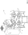
- a machine 100 for welding a medical bag 200 made of a plastic material is represented.
- Said medical bag 200 is generally composed of a first sheet 202, to which a second sheet 203 is superimposed, which are welded one to the other by preferably peripheral welding that is adapted to define an inner volume V of the medical bag 200; before carrying out said peripheral welding, one or more tubes 201, also made of a plastic material, are interposed between the first sheet 202 and the second sheet 203, arranged in a peripheral position so as to be exiting towards the exterior of the medical bag 200, so that a tube portion remains inside the peripheral welding and a tube portion projects outwardly to put the inner volume V of the medical bag 200 in communication with the exterior.
- the tubes 201 arranged as described are then welded both to the first sheet 202 and the second sheet 203.
- the machine 100 that is the subject-matter of the present finding is configured so as to be able to manage in a flexible manner different types of medical bags 200; for example, it is able to weld tubes 201 having different diameters, and it is able to manage different configurations, which may provide for even more than one tube 201 for each side of the medical bag 200.
- the peripheral welding of the first sheet 202 and the second sheet 203, as well as the welding of the tubes 201, is carried out by a high-frequency current of the order of 27-40 MegaHertz.
- the machine 100 comprises:
- Said press comprises, in turn, an upper plate 3, a lower plate 4 and a protective screen 6.
- a preferred embodiment provides for an electrode 31 is mechanically associated to the upper plate 3, while it provides for a counter-electrode 41 that is electrically connected to the ground is mechanically associated to the lower plate 4.
- the electrode 31 is also referred to as the active electrode, since it transmits current to the counter-electrode 41, which instead is also referred to as the passive electrode, since it is configured to receive said current coming from the electrode 31.
- the upper plate 3, which is part of the press 2 is movable and configured to bring the electrode 31 and the counter-electrode 41 in contact one to the other and allow the passage of the current both for the peripheral welding of the sheets 202 and 203 and for the welding of the tubes 201; during the contact, a pressure required to complete the welding is exerted.
- An embodiment of the finding provides that the counter-electrode 41 is configured to support the first sheet 202 to which the second sheet 203 is superimposed in a resting relationship.
- the lower plate 4 further comprises tube-holder mandrels 42 configured to hold the tubes 201 in place and to transmit the high-frequency current thereto.
- Said tube-holder mandrels 42 are preferably arranged on each side of the medical bag 200 in which the tubes 201 to be welded are present.
- each tube-holder mandrel 42 are preferably made of brass or aluminium and so shaped that each tube-holder mandrel 42 comprises at least one projection 42a that is adapted to insert inside each tube 201, which is present on a side of the medical bag 200; said projection 42a is so shaped as to allow the passage of current inside the tubes 201; in fact, following the simultaneous action of the pressure exerted by the welding press 2 and the molecular agitation induced on the tube 201 by the high-frequency current, a rise of the temperature of the tube 201 occurs, which causes the melting and the consequent welding thereof.
- a preferred embodiment provides for the high-frequency generator 1 is electrically connected to the electrical circuit 5 to transmit the high-frequency current necessary, both for the peripheral welding of the sheets 202 and 203, and for the welding of the tubes 201.
- Said electrical circuit 5 may branch into: a first circuit, which is referred to as a reticulated circuit 53 in the technical jargon, a second circuit or direct circuit 52. This occurs by a main switch 54 that is movable between two positions: one that connects the generator 1 with the first circuit 53 and one that connects it with the second circuit 52 in an alternating manner.
- the main switch 54 is in such position as to connect the generator 1 with the first circuit 53, when the welding of the tubes 201 has to be performed, while it is in such a position as to connect the generator 1 with the second circuit 52, when the peripheral welding of the sheets 202 and 203 has to be performed.
- the first circuit 53 comprises a plurality of conductive members 53b, preferably one for each side of the medical bag 200, suitable to bring high-frequency power to the tube-holder mandrels 42 when the press 2 is in an operative step for the welding of the tubes 201.
- the first circuit 53 further comprises a plurality of secondary switching devices 53a, preferably one for each side of the perimeter of the bag 200 where the tubes 201 are present.
- These secondary switching devices 53a serve to connect/disconnect the respective conductive members 53b; therefore, as in the case represented in the figures, if tubes 201 are present on all the four sides of the bag, 4 secondary switching devices 53a will be provided.
- Said secondary switching devices 53a are configured to take an open position and a closed position, where the position allowing the passage of current is referred to as the closed position.
- an embodiment provides that the secondary switching devices 53a are actuated between the open and closed positions by means of pneumatic cylinders.
- the secondary switching devices 53a are preferably arranged on the associated conductive members 53b on the sides of the medical bag 200, in which a tube 201 is provided, and arranged in parallel, so that it is possible to manage the welding of the various tubes 201 even separately.
- Said conductive members 53b are preferably planar surfaces that are made of aluminium so that they are suitable in their shape, dimensions, and material, to the conduction of high-frequency alternating current.
- the second circuit 52 is configured to bring the current directly on the electrode 31, which, in turn, transfers it to the counter-electrode 41 when the press 2 is in the closed position and is in the operative step of peripheral welding of the sheets 202 and 203.
- the position of the main switch 54 defines the welding step to be carried out, i.e., the peripheral welding if it is connected to the second circuit 52, or the welding of the tubes if it is connected to the first circuit 53, and in such a case the welding occurs on the branches of the first circuit 53b, the respective secondary switching device 53a of which will be closed.
- said first circuit 53 is mechanically connected to the upper plate 3 and to the protective screen 6 by insulators 56.
- said first circuit 53 is positioned so as to be sufficiently far from all the conductive parts that are present in the press 2 such as, for example, the upper plate 3.
- a preferred embodiment provides that the distance between the first circuit 53 and the nearest conductive point is not lower than 10mm, and preferably of about 20mm, to ensure the maximum safety.
- the conductive members 53b of the first circuit 53 are positioned so that their distance from the nearest conductive point is equal to or greater than 10 mm, o further preferably so that the distance from the nearest conductive point is equal to or greater than 20mm.
- the medical bags 200 of a larger dimension are implemented with an upper 3 and a lower 4 plates having dimensions as much reduced as possible, which preferably do not exceed 450x550mm.
- the reduced dimensions together with the need to manufacture medical bags 200 with more than two welded tubes 201, generates considerable difficulties, especially in balancing the welding, due to the considerable geometric proximity of those points in which said welding has to be carried out.
- Object of the present invention is to allow the implementation of a machine 100 that is capable to implement, within reduced spaces, medical bags 200 having a plurality of tubes 201 even with different diameters, ensuring a high-quality level of the welding.
- a formulation of the present finding provides to implement a welding press 2, which further comprises a capacitor 7 that is electrically connected to the plate 3 and arranged to be connected on the other side to the ground by a switching device 71 configured to move between a first closed position A, which connects the capacitor 7 to the ground reference, and a second open position B, which releases the ground connection of the capacitor 7.
- Said switching device 71 is in the first closed position A when the machine 100 carries out the welding of the tubes 201, i.e., when the generator 1 supplies the first circuit 53, vice versa, it is in the second open position B, when the machine 100 carries out the peripheral welding of the sheets 202 and 203, i.e., when the generator 1 supplies the second circuit 52.
- the switching device 71 is actuated by a pneumatic command 72 as represented in Fig. 2 .
- Function of the capacitor 7 is to create a preferential path to the return passage of the alternating current during the welding of the tubes 201 so as to equilibrate the distribution of said alternating current, in particular between the upper and lower walls of the tube 201.
- This configuration allows ensuring high quality standards, which require the symmetry of the welding and a non-ovalization of the tube 201, in addition to a high seal of the welding.
- a preferred embodiment provides for the capacitor 7 to be mechanically and electrically secured on the upper plate 3 and, if needed, electrically connected to the ground by the switching device 71 which, in turn, as represented in Fig. 2 , comprises a first inductor member 73, which connects the capacitor 7 to the ground when the switching device is in the closed position A.
- said first inductor member 73 is manufactured in the shape of a copper or silver strap, secured in contact with the protective screen 6, which is, in turn, connected to the ground.
- the switching device 71 When the machine 100 is in the operative step of welding of the tubes 201, the switching device 71 is in the first closed position A, which brings the capacitor 7 in contact with the protective screen 6 so as to reduce the call-back effect of the current by the lower plate 4.
- part of the current is called back by the capacitor 7 towards the upper plate 3. This allows balancing the current that flows in the upper and lower walls of the tubes 201, thus generating a uniformity of welding.
- the switching device 71 is in the second closed position B so that the capacitor 7 is irrelevant and operatively excluded, in order not to adversely affect the distribution of the current for the peripheral welding, which in this step passes exactly from the upper electrode 31 to the counter-electrode 41.
- the capacitor 7 is preferably of a ceramic type, but it could also be mechanically built.
- the first inductor member 73 is adapted to electrically define a variable inductance as a function of the length and width thereof; said inductance can be dimensioned as a function of the number and the dimension of the tubes 201 to be welded. In this manner, it is possible to balance the amount of current between the lower and upper walls of the tubes 201 to the best.
- the welding press 2 further comprises at least one secondary capacitor 8 operatively associated to each side of the medical bag 200 where at least one tube 201 to be welded is present.
- Said at least one secondary capacitor 8 is electrically and mechanically associated to the conductive members 53b of the first circuit 53.
- the capacitor 8 is preferably positioned on the first circuit 53 with one side being in contact with the conductive member 53b.
- an embodiment provides for a capacitor on each side of the first circuit 53 in which at least one tube 201 to be welded is present.
- Each secondary capacitor 8 is then electrically and mechanically connected to the ground by a secondary inductor member 81 preferably manufactured in the shape of a copper or silver strap, which connect them to the protective screen 6, with a ground reference; said secondary inductor member 81 defined an inductance that is preferably dimensioned as a function of the dimension of the tubes 201 of the side of the medical bag 200 which it is associated to.
- a further possible embodiment may provide for a capacitor 8 for each tube 201 to be welded.
- Said secondary capacitors 8 in a preferred embodiment, are configured to be positioned again on the conductive member 53b, in the case that the position of the tube 201 to be welded changes, or replaced, in the case that the dimension of the tube 201 changes.
- Said capacitors 8 are intended to adjust the distribution of the alternating current of each individual side of the bag 200 in order to optimize the welding of the tubes 201 of each side.
- each capacitor 8 has to be dimensioned so as to cope with the dimensional differences of the tubes 201 and their different position, which involves different cases of distribution of the current on the path of the reticulated circuit 53.
- Said secondary capacitors 8 become indispensable in a machine 100 in which more than two sides of tubes 201 to be welded are present, and mainly in the case that the tubes 201 are on all the sides of the medical bag 200, and furthermore if said tubes 201 have different diameters; in fact, this configuration involves power needs that are different on each side.
- the secondary capacitors 8 become mainly necessary if it is decided to weld the tubes 201 of multiple sides in a single welding step.
- the welding of the tubes 201 may occur both in a sequential and in a simultaneous manner; the latter is performed in order to reduce the implementation times of the medical bag 200, therefore to increase the production output of the machine.
- the machine 100 as configured allows a wide range of adjustment, thus allowing to implement several configurations of medical bags 200, where the position and the dimension of the tubes 201 can be varied along the sides of the medical bag 200.
- the main function of the capacitor 7 is to balance the distribution of the alternating current between the upper and lower walls of each tube 201
- the function of the capacitors 8 is to more finely tune the distribution of the alternating current on each individual side of the bag 200 ensuring the uniformity of welding for all the tubes 201.
Landscapes
- Engineering & Computer Science (AREA)
- Mechanical Engineering (AREA)
- Lining Or Joining Of Plastics Or The Like (AREA)
- Medical Preparation Storing Or Oral Administration Devices (AREA)
- External Artificial Organs (AREA)
Description
- The present finding relates to the field of the welding apparatuses for plastic objects and, more precisely, the machine according to the present invention welds and produces medical bags.
- Machines for welding plastic materials that provide for carrying out said welding by means of a technology, which is referred to as high-frequency or radio-frequency welding, are known from the state of the art.
- Following the molecular agitation induced onto the plastic materials by the simultaneous action of the pressure and the electromagnetic field, a rise in the temperature occurs, which causes the melting and the subsequent welding thereof. The high-frequency welding process ensures a safe and durable joining of different product, also with long lifetimes.
- The materials that can be welded with this technique are especially PVC, either flexible or rigid, EVA (ethyl-vinyl-acetate), TPU (polyurethane), and polyolefines.
- Among the several applications provided for such machines, there is the welding for producing medical bags.
- Said medical bags mainly provide for one or more peripheral weldings of two sheets/films made of a plastic material that are overlapped to compose the bag and a welding of one or more tubes, also made of a plastic material, interposed between the two sheets/films and welded preferably in a peripheral position, so arranged as to be exiting towards the exterior of the bag.
- Machines for welding medical bags by radiofrequency, which are able to weld, with quality, tubes on at most two sides of the bag are known.
- Document
EP0633127 discloses a method ad apparatus making flexible film pouches having fitment tubes attached thereto. The process includes a single operation for the simultaneous sealing of the pouch edge seams and the fitment tubes to the pouch. - Similarly
US2816596 relates generally to the manufacture of fluid handling equipment and apparatus and more particularly to uniting sheet and tube components of such apparatus and by dielectric heat sealing method and means. - In known machines, a press is generally present, which comprises a lower plate, which provides for a mould referred to as the counter-electrode, on which the several materials that will compose the bag and that have to be welded are positioned.
- During the operative step, an upper plate comprising an electrode for the transmission of high-frequency current overlaps to this lower plate.
- In said machines, the welding process usually involves high-frequency electrical currents, of the order of 27-40 MegaHertz.
- A high-frequency generator is the element on which this technology is based, which is configured to transform a standard mains voltage into an alternating voltage that is even five times higher.
- The critical issue of this technology originates in the fact that the apparatus carries out the welding in succession or concomitantly on different parts of the object, operating in a very reduced space.
- During the high-frequency welding inside the welding machine that is the subject-matter, the intensity of the electric field exceeds 1000 Volts/meter and, under these conditions, the geometry and the positioning of each minimal component may turn out to be disastrous, with combined disturbance to the welding of the various parts of the product to be welded.
- The difficulty occurs mainly in manufacturing bags with tubes welded on more than one side; in fact, said bags habe reduced dimensions (at most, 300x400mm) and this involves considerable problems in balancing the welding, precisely due to the geometric proximity of those points in which said welding has to be carried out.
- Since the space for the paths of the high-frequency alternating current is very limited, there is a high risk that disturbances are triggered, or that abnormal paths of said currents are generated.
- Furthermore, the alternating current, in the known machines, tends to prefer, as a return path, during the welding of the tubes, the counter-electrode that is connected to the ground; on the contrary, the electrode does not "call" the return of the current, since, during the welding of the tube, it has not a reference that connects it to the ground.
- This involves the implementation of weldings with sub-optimal qualitative levels, and the problem mainly occurs in welding the tubes.
- Often, said tubes are not evenly welded to the plastic film, and obvious differences occur between the welding of the upper wall thereof (facing the upper plate) with respect to the lower wall thereof (facing the lower plate). In order to make the welding of the tube in the upper and lower parts thereof more uniform, generally a high pressure of the upper plate on the lower one is exerted, with a high risk of damaging the tubes, bringing them to an ovalization.
- Another known solution is to arrange mechanical stops under the tube-holder mandrels (into which the tubes are inserted) to keep them under an upward pressure; however, this bends, arches, and damages within a short time said mandrels.
- Furthermore, in the case that the tubes have different diameters, it is extremely difficult to ensure that the proper amount of current arrives to the various tubes as a function of the dimension thereof and the possible resistances that the current may run across in the path between the generator and the individual tube.
- A further problem that is found in the traditional machines for manufacturing medical bags with more than two tubes is connected to the production output, because there are very high manufacturing times, since, in order to achieve a better result, it is preferred that the tubes are welded in succession, but not simultaneously.
- The technical problem underlying the present invention is to provide to the art a machine for the high-frequency welding of medical bags structurally and functionally devised to overcome one or more of the limitations set forth above with reference to the mentioned prior art.
- Within the scope of the above-mentioned problem, a main object of the invention is to develop a machine for the high-frequency welding of medical bags that allows making the distribution of the alternating current between the upper wall and the lower one of each individual tube uniform.
- A further object of the invention is also to provide to the art a machine for the high-frequency welding of medical bags within the scope of a solution that allows welding tubes on more than two sides of the medical bag, in different positions and with also different diameters, while ensuring a high-quality level of the welding between the tube and the film.
- Such and other objects are achieved by virtue of the characteristics of the invention set forth in the independent claims. The dependent claims outline preferred and/o particularly advantageous aspects of the invention.
- In particular, an implementation of the present invention provides a machine for welding a medical bag, which is made of a plastic material, that is configured to weld a plurality of tubes between a first sheet and a second sheet, and to carry out at least one peripheral welding of the two sheets, comprising a welding press and a high-frequency generator which, by means of a main switch, supplies in an alternating manner either a reticulated circuit configured to weld the tubes or a direct circuit configured to peripherally weld the sheets, where said welding press comprises, in turn, an upper plate to which an electrode suitable to be electrically supplied through the direct circuit is mechanically associated, and a lower plate to which a counter-electrode and locking members are mechanically associated, where the counter-electrode is configured to receive power from the electrode and where the tube-holder mandrels are electrically connected to the reticulated circuit and configured to hold the tubes in place; the welding press further comprises a capacitor, which is electrically connected to the upper plate and connectable to the ground by a switching device that is configured to selectively open/close an electric contact between a closed position, which connects the capacitor to the ground, and an open position, which releases the capacitor from the ground connection, where the position contact is taken when the generator supplies the first circuit to weld the tubes.
- By virtue of this solution, during the welding of the tubes, part of the current, which would otherwise tend to direct itself towards the lower plate that is connected to the ground, is called back by the capacitor towards the upper plate, thus allowing balancing the current that flows in the upper and lower walls of the tubes to implement a uniform welding. A further advantage is also given by the fact that this better distribution of the current allows reducing the closing pressure of the welding press, thus reducing the risk of an ovalization of the tubes or a damage to the locking members.
- Another aspect of the invention is to provide a welding press in which the switching device comprises a first inductor member, which connects the capacitor to the ground when the switching device is in the closed position.
- By virtue of said inductor member that is dimensioned as a function of the number and the dimension of the tubes, it is possible to further balance the distribution of the alternating current.
- According to a further aspect of the invention, the welding press further comprises at least one secondary capacitor mechanically associated to conductive members of the first circuit, where said conductive members are suitable to bring power to the tube-holder mandrels.
- A preferred form provides a conductive member and a corresponding secondary capacitor for each side of the medical bag in which the tubes to be welded are present.
- This solution allows adjusting the distribution of the alternating current of each individual side of the bag in order to optimize the welding of the tubes of each side.
- In accordance with an aspect of the invention, each secondary capacitor is electrically and mechanically associated to a secondary inductor member arranged between the capacitor and the ground connection, which defines an inductance that is dimensioned as a function of the dimension and the number of tubes of the side of the medical bag which it is operatively associated to.
- Furthermore, an embodiment provides that the secondary capacitors can be moved along the corresponding conductive member.
- In such a manner, the distribution of the current on the individual tubes is further optimized, in order to achieve an accurate, uniform, and resistant welding.
- A preferred embodiment provides for the conductive members to be connected to the ground through the secondary capacitor and are configured to be electrically supplied by a switching device, which is configured to selectively open/close an electric contact of the first circuit.
- Said switching devices of each conductive member are configured to be supplied in parallel so that, during an operative step, only those members that are operatively associated to the sides of the medical bag to be welded are actuated.
- By virtue of this solution, it is possible to weld either in a sequential or non-sequential manner the various sides of the medical bag.
- Object of the present invention is also to maintain reduced dimensions of the welding press, without incurring the risk that disturbances are triggered, or that abnormal paths of said currents are generated.
- For such a reason, the finding provides that the distance of the reticulated circuit from the nearest conductive point has to be greater than or equal to 10 mm, and preferably about 20mm.
- Said objects and advantages are all achieved by the machine for welding a medical bag made of a plastic material, which is the subject-matter of the present finding, which is characterized by what is provided for in the claims set forth herein below.
- This and other characteristics will be more clearly pointed out by the following description of some embodiments, which are illustrated, by way of non-limiting example only, in the attached drawing figures.
-
Fig. 1 : illustrates in axonometric view a machine for welding medical bags; -
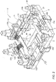
Fig. 2 : illustrates in axonometric view a welding press; in particular, the upper plate and the direct circuit and the reticulated circuit are clearly visible; -
Fig. 3 : illustrates in axonometric view a welding press; in particular, the lower plate and the counter-electrode are clearly visible; -
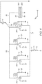
Fig. 4 : illustrates a scheme of the electrical circuit of the machine for welding a medical bag. - With particular reference to
Fig. 1 , amachine 100 for welding a medical bag 200 made of a plastic material is represented. - Said medical bag 200 is generally composed of a
first sheet 202, to which asecond sheet 203 is superimposed, which are welded one to the other by preferably peripheral welding that is adapted to define an inner volume V of the medical bag 200; before carrying out said peripheral welding, one ormore tubes 201, also made of a plastic material, are interposed between thefirst sheet 202 and thesecond sheet 203, arranged in a peripheral position so as to be exiting towards the exterior of the medical bag 200, so that a tube portion remains inside the peripheral welding and a tube portion projects outwardly to put the inner volume V of the medical bag 200 in communication with the exterior. Thetubes 201 arranged as described are then welded both to thefirst sheet 202 and thesecond sheet 203. - The
machine 100 that is the subject-matter of the present finding is configured so as to be able to manage in a flexible manner different types of medical bags 200; for example, it is able to weldtubes 201 having different diameters, and it is able to manage different configurations, which may provide for even more than onetube 201 for each side of the medical bag 200. - The peripheral welding of the
first sheet 202 and thesecond sheet 203, as well as the welding of thetubes 201, is carried out by a high-frequency current of the order of 27-40 MegaHertz. - According to an aspect of the finding, the
machine 100 comprises: - a high-frequency generator 1 electrically connected to an
electrical circuit 5, - a
welding press 2, - Said press comprises, in turn, an
upper plate 3, a lower plate 4 and a protective screen 6. - A preferred embodiment provides for an
electrode 31 is mechanically associated to theupper plate 3, while it provides for a counter-electrode 41 that is electrically connected to the ground is mechanically associated to the lower plate 4. - The
electrode 31 is also referred to as the active electrode, since it transmits current to the counter-electrode 41, which instead is also referred to as the passive electrode, since it is configured to receive said current coming from theelectrode 31. - According to an aspect of the finding, the
upper plate 3, which is part of thepress 2, is movable and configured to bring theelectrode 31 and the counter-electrode 41 in contact one to the other and allow the passage of the current both for the peripheral welding of thesheets tubes 201; during the contact, a pressure required to complete the welding is exerted. - An embodiment of the finding provides that the counter-electrode 41 is configured to support the
first sheet 202 to which thesecond sheet 203 is superimposed in a resting relationship. - In a preferred embodiment, the lower plate 4 further comprises tube-
holder mandrels 42 configured to hold thetubes 201 in place and to transmit the high-frequency current thereto. Said tube-holder mandrels 42 are preferably arranged on each side of the medical bag 200 in which thetubes 201 to be welded are present. - According to an aspect of the finding, said tube-
holder mandrels 42 are preferably made of brass or aluminium and so shaped that each tube-holder mandrel 42 comprises at least oneprojection 42a that is adapted to insert inside eachtube 201, which is present on a side of the medical bag 200; saidprojection 42a is so shaped as to allow the passage of current inside thetubes 201; in fact, following the simultaneous action of the pressure exerted by thewelding press 2 and the molecular agitation induced on thetube 201 by the high-frequency current, a rise of the temperature of thetube 201 occurs, which causes the melting and the consequent welding thereof. - A preferred embodiment provides for the high-frequency generator 1 is electrically connected to the
electrical circuit 5 to transmit the high-frequency current necessary, both for the peripheral welding of thesheets tubes 201. - Said
electrical circuit 5 may branch into: a first circuit, which is referred to as areticulated circuit 53 in the technical jargon, a second circuit ordirect circuit 52. This occurs by amain switch 54 that is movable between two positions: one that connects the generator 1 with thefirst circuit 53 and one that connects it with thesecond circuit 52 in an alternating manner. - The
main switch 54 is in such position as to connect the generator 1 with thefirst circuit 53, when the welding of thetubes 201 has to be performed, while it is in such a position as to connect the generator 1 with thesecond circuit 52, when the peripheral welding of thesheets - According to a preferred embodiment, the
first circuit 53 comprises a plurality ofconductive members 53b, preferably one for each side of the medical bag 200, suitable to bring high-frequency power to the tube-holder mandrels 42 when thepress 2 is in an operative step for the welding of thetubes 201. - As represented in
Fig. 2 or in the circuit diagram ofFig. 4 , thefirst circuit 53 further comprises a plurality ofsecondary switching devices 53a, preferably one for each side of the perimeter of the bag 200 where thetubes 201 are present. Thesesecondary switching devices 53a serve to connect/disconnect the respectiveconductive members 53b; therefore, as in the case represented in the figures, iftubes 201 are present on all the four sides of the bag, 4secondary switching devices 53a will be provided. - Said
secondary switching devices 53a are configured to take an open position and a closed position, where the position allowing the passage of current is referred to as the closed position. - As represented in
Fig. 2 , an embodiment provides that thesecondary switching devices 53a are actuated between the open and closed positions by means of pneumatic cylinders. - As represented in the circuit diagram of
Fig. 4 , thesecondary switching devices 53a are preferably arranged on the associatedconductive members 53b on the sides of the medical bag 200, in which atube 201 is provided, and arranged in parallel, so that it is possible to manage the welding of thevarious tubes 201 even separately. - Said
conductive members 53b are preferably planar surfaces that are made of aluminium so that they are suitable in their shape, dimensions, and material, to the conduction of high-frequency alternating current. - On the contrary, the
second circuit 52 is configured to bring the current directly on theelectrode 31, which, in turn, transfers it to the counter-electrode 41 when thepress 2 is in the closed position and is in the operative step of peripheral welding of thesheets - Therefore, the position of the
main switch 54 defines the welding step to be carried out, i.e., the peripheral welding if it is connected to thesecond circuit 52, or the welding of the tubes if it is connected to thefirst circuit 53, and in such a case the welding occurs on the branches of thefirst circuit 53b, the respectivesecondary switching device 53a of which will be closed. - According to a possible embodiment, said
first circuit 53 is mechanically connected to theupper plate 3 and to the protective screen 6 byinsulators 56. - In accordance with an aspect of the finding, said
first circuit 53 is positioned so as to be sufficiently far from all the conductive parts that are present in thepress 2 such as, for example, theupper plate 3. - This distance is necessary in order to avoid that, during the welding step of the
tubes 201, the current follows improper paths, thus dispersing in areas where it is not required, with the risk that there is not a sufficient concentration of said current on the tube-holder mandrels 42 that have to receive it in order to weld thetubes 201. These dispersions also involve conseguent safety problems. - A preferred embodiment provides that the distance between the
first circuit 53 and the nearest conductive point is not lower than 10mm, and preferably of about 20mm, to ensure the maximum safety. - Therefore, the
conductive members 53b of thefirst circuit 53 are positioned so that their distance from the nearest conductive point is equal to or greater than 10 mm, o further preferably so that the distance from the nearest conductive point is equal to or greater than 20mm. - Greater distances involve considerable dimensional problems, which compromise the functional characteristics of the
machine 100. - Furthermore, generally, the medical bags 200 of a larger dimension are implemented with an upper 3 and a lower 4 plates having dimensions as much reduced as possible, which preferably do not exceed 450x550mm. The reduced dimensions, together with the need to manufacture medical bags 200 with more than two welded
tubes 201, generates considerable difficulties, especially in balancing the welding, due to the considerable geometric proximity of those points in which said welding has to be carried out. - Since the space for the paths of the high-frequency alternating current is very reduced, there is a high risk that disturbances are triggered, or that abnormal paths of said currents are generated.
- Object of the present invention is to allow the implementation of a
machine 100 that is capable to implement, within reduced spaces, medical bags 200 having a plurality oftubes 201 even with different diameters, ensuring a high-quality level of the welding. - Due to this reason, a formulation of the present finding provides to implement a
welding press 2, which further comprises acapacitor 7 that is electrically connected to theplate 3 and arranged to be connected on the other side to the ground by aswitching device 71 configured to move between a first closed position A, which connects thecapacitor 7 to the ground reference, and a second open position B, which releases the ground connection of thecapacitor 7. - Said switching
device 71 is in the first closed position A when themachine 100 carries out the welding of thetubes 201, i.e., when the generator 1 supplies thefirst circuit 53, vice versa, it is in the second open position B, when themachine 100 carries out the peripheral welding of thesheets second circuit 52. - In accordance with a possible embodiment, the switching
device 71 is actuated by apneumatic command 72 as represented inFig. 2 . - Function of the
capacitor 7 is to create a preferential path to the return passage of the alternating current during the welding of thetubes 201 so as to equilibrate the distribution of said alternating current, in particular between the upper and lower walls of thetube 201. - This configuration allows ensuring high quality standards, which require the symmetry of the welding and a non-ovalization of the
tube 201, in addition to a high seal of the welding. - What happens in the absence of the
capacitor 7 is described below: - the
switch 54 is in such a position as to allow the passage of the current on thefirst circuit 53 to get to the tube-holder mandrels 42 (only in the branches in which thesecondary switching device 53a turns out to be closed); therefore, from the tube-holder mandrel 42 the current flows into therespective tube 201, but in a non-uniform manner, i.e., it preferentially flows along the lower wall of thetube 201, i.e., the wall of thetube 201 facing the lower plate 4; this occurs because the lower plate 4, to which the tube-holder mandrels 42 are mechanically connected, is connected to the ground; therefore, it tends to call the alternating current most; on the contrary, theupper plate 3, has not a ground reference, therefore it does not call the return of the current, thus carrying a lower amount of current along the upper wall of thetube 201, i.e., the wall of thetube 201 facing theupper plate 3. - This involves a larger welding of the lower wall of the
tube 201 compared to the upper one. - A preferred embodiment provides for the
capacitor 7 to be mechanically and electrically secured on theupper plate 3 and, if needed, electrically connected to the ground by the switchingdevice 71 which, in turn, as represented inFig. 2 , comprises afirst inductor member 73, which connects thecapacitor 7 to the ground when the switching device is in the closed position A. - Preferably said
first inductor member 73 is manufactured in the shape of a copper or silver strap, secured in contact with the protective screen 6, which is, in turn, connected to the ground. - When the
machine 100 is in the operative step of welding of thetubes 201, the switchingdevice 71 is in the first closed position A, which brings thecapacitor 7 in contact with the protective screen 6 so as to reduce the call-back effect of the current by the lower plate 4. - In fact, in such a manner, part of the current is called back by the
capacitor 7 towards theupper plate 3. This allows balancing the current that flows in the upper and lower walls of thetubes 201, thus generating a uniformity of welding. - On the contrary, when the
machine 100 is in the operative step of peripheral welding, the switchingdevice 71 is in the second closed position B so that thecapacitor 7 is irrelevant and operatively excluded, in order not to adversely affect the distribution of the current for the peripheral welding, which in this step passes exactly from theupper electrode 31 to the counter-electrode 41. - An aspect of the finding provides that, for convenience's sake, the
capacitor 7 is preferably of a ceramic type, but it could also be mechanically built. - The
first inductor member 73 is adapted to electrically define a variable inductance as a function of the length and width thereof; said inductance can be dimensioned as a function of the number and the dimension of thetubes 201 to be welded. In this manner, it is possible to balance the amount of current between the lower and upper walls of thetubes 201 to the best. - According to a further preferred embodiment, the
welding press 2 further comprises at least onesecondary capacitor 8 operatively associated to each side of the medical bag 200 where at least onetube 201 to be welded is present. - Said at least one
secondary capacitor 8 is electrically and mechanically associated to theconductive members 53b of thefirst circuit 53. - The
capacitor 8 is preferably positioned on thefirst circuit 53 with one side being in contact with theconductive member 53b. - As represented in
Fig. 2 and in the circuit diagram ofFig. 4 , an embodiment provides for a capacitor on each side of thefirst circuit 53 in which at least onetube 201 to be welded is present. - Each
secondary capacitor 8 is then electrically and mechanically connected to the ground by asecondary inductor member 81 preferably manufactured in the shape of a copper or silver strap, which connect them to the protective screen 6, with a ground reference; saidsecondary inductor member 81 defined an inductance that is preferably dimensioned as a function of the dimension of thetubes 201 of the side of the medical bag 200 which it is associated to. - A further possible embodiment may provide for a
capacitor 8 for eachtube 201 to be welded. - Said
secondary capacitors 8, in a preferred embodiment, are configured to be positioned again on theconductive member 53b, in the case that the position of thetube 201 to be welded changes, or replaced, in the case that the dimension of thetube 201 changes. - Said
capacitors 8 are intended to adjust the distribution of the alternating current of each individual side of the bag 200 in order to optimize the welding of thetubes 201 of each side. - In fact, they allow dosing the current on the
conductive members 53b, since, as a function of the extent of the capacity thereof, they call an amount of current that is different on each side of the medical bag 200. - Therefore, the capacity of each
capacitor 8 has to be dimensioned so as to cope with the dimensional differences of thetubes 201 and their different position, which involves different cases of distribution of the current on the path of thereticulated circuit 53. - Said
secondary capacitors 8 become indispensable in amachine 100 in which more than two sides oftubes 201 to be welded are present, and mainly in the case that thetubes 201 are on all the sides of the medical bag 200, and furthermore if saidtubes 201 have different diameters; in fact, this configuration involves power needs that are different on each side. - The
secondary capacitors 8 become mainly necessary if it is decided to weld thetubes 201 of multiple sides in a single welding step. - In, fact, the welding of the
tubes 201 may occur both in a sequential and in a simultaneous manner; the latter is performed in order to reduce the implementation times of the medical bag 200, therefore to increase the production output of the machine. - By virtue of said
secondary capacitors 8, it is possible to ensure a high uniformity of welding of thetubes 201 and reliability of the result, besides a high production output of themachine 100. - Furthermore, the
machine 100 as configured allows a wide range of adjustment, thus allowing to implement several configurations of medical bags 200, where the position and the dimension of thetubes 201 can be varied along the sides of the medical bag 200. - Therefore, while the main function of the
capacitor 7 is to balance the distribution of the alternating current between the upper and lower walls of eachtube 201, the function of thecapacitors 8 is to more finely tune the distribution of the alternating current on each individual side of the bag 200 ensuring the uniformity of welding for all thetubes 201. - However, it is intended that what has been described above is of a non-limiting, exemplary value.
Claims (11)
- A machine (100) for welding a medical bag (200) made of a plastic material and comprising a first sheet (202) and a second sheet (203) separated by a plurality of tubes (201), the machine (100) being configured to weld the tubes (201) between the first sheet (202) and the second sheet (203) and to carry out at least one peripheral welding of the two sheets (202, 203) and comprising a welding press (2) and a high-frequency generator (1) which, by means of a main switch (54), supplies in an alternating manner either a first circuit (53) configured to weld the tubes (201) or a second circuit (52) configured to peripherally weld the sheets (202, 203), wherein said welding press (2) comprises, in turn:- an upper plate (3) to which an electrode (31) suitable to be electrically supplied through the second circuit (52) is mechanically associated,- a lower plate (4) to which a counter-electrode (41) and tube-holder mandrels (42) are mechanically associated, where the counter-electrode (41) is configured to receive power from the electrode (31) and where the tube-holder mandrels (42) are electrically connected to the first circuit (53) and configured to hold the tubes (201) in place,the machine (100) being characterized in that the welding press (2) further comprises a capacitor (7) electrically connected to the upper plate (3) and connectable to the ground by a switching device (71) configured to selectively open/close an electric contact between a closed position (A), which connects the capacitor (7) to the ground, and an open position (B), which releases the capacitor (7) from the ground connection, where the closed position (A) is taken when the generator (1) supplies the first circuit (53) to weld the tubes (201).
- The machine (100) for welding a medical bag (200) according to claim 1, wherein the switching device 71 is in the open position (B), when the generator (1) supplies the second circuit (52) for the peripheral welding of the sheets (202, 203).
- The machine (100) for welding a medical bag (200) according to the preceding claims, wherein the switching device (71) comprises a primo un inductor member (73) which connects the capacitor (7) to the ground when the switching device is in the closed position (A).
- The machine (100) for welding a medical bag (200) according to the preceding claims, wherein the welding press (2) further comprises at least one secondary capacitor (8) mechanically associated to conductive members (53b) of the first circuit (53), where said conductive members (53b) are suitable to bring power to the tube-holder mandrels (42).
- The machine (100) for welding a medical bag (200) according to claim 4, wherein the conductive members (53b) are connected to the ground by the secondary capacitor (8) and configured to be electrically supplied by a secondary switching device (53a), which is configured to selectively open/close an electric contact of the first circuit (53).
- The machine (100) for welding a medical bag (200) according to the claims 4 and 5, wherein a conductive member (53b) and a corresponding secondary capacitor (8) are provided for each side of the medical bag (200) in which the tubes (201) to be welded are present.
- The machine (100) for welding a medical bag (200) according to one of the claims 4 to 6, wherein a secondary inductor member (81) arranged between the capacitor (8) and the ground connection is electrically and mechanically associated to each secondary capacitor (8).
- The machine (100) for welding a medical bag (200) according to one of the claims 4 to 7, wherein the secondary switching devices (53a) of each conductive member (53b) are configured to be supplied in parallel so that, during an operative step, only those members that are operatively associated to the sides of the medical bag (200) to be welded are actuated.
- The machine (100) for welding a medical bag (200) according to one of the claims 4 to 8, wherein the secondary capacitors (8) are configured to be moved along the conductive members (53b).
- The machine (100) for welding a medical bag (200) according to one of the claims 2 to 4, wherein the first circuit (53) is positioned so that the distance thereof from the nearest conductive point is equal to or greater than 10 mm.
- The machine (100) for welding a medical bag (200) according to one of the claims 2 to 4, wherein the first circuit (53) is positioned so that the distance thereof from the nearest conductive point is equal to or greater than 20mm.
Applications Claiming Priority (1)
| Application Number | Priority Date | Filing Date | Title |
|---|---|---|---|
| IT102018000002760A IT201800002760A1 (en) | 2018-02-16 | 2018-02-16 | MACHINE FOR THE WELDING OF A MEDICAL BAG IN PLASTIC MATERIAL |
Publications (2)
| Publication Number | Publication Date |
|---|---|
| EP3527354A1 EP3527354A1 (en) | 2019-08-21 |
| EP3527354B1 true EP3527354B1 (en) | 2021-02-03 |
Family
ID=62143508
Family Applications (1)
| Application Number | Title | Priority Date | Filing Date |
|---|---|---|---|
| EP19157305.4A Active EP3527354B1 (en) | 2018-02-16 | 2019-02-14 | Machine for welding a medical bag made of a plastic material |
Country Status (2)
| Country | Link |
|---|---|
| EP (1) | EP3527354B1 (en) |
| IT (1) | IT201800002760A1 (en) |
Family Cites Families (2)
| Publication number | Priority date | Publication date | Assignee | Title |
|---|---|---|---|---|
| US2816596A (en) * | 1955-08-09 | 1957-12-17 | Fenwal Lab Inc | Dielectric heat sealing method and apparatus |
| US5437595A (en) * | 1993-07-08 | 1995-08-01 | W. R. Grace & Co. | Method and apparatus for producing medical pouches |
-
2018
- 2018-02-16 IT IT102018000002760A patent/IT201800002760A1/en unknown
-
2019
- 2019-02-14 EP EP19157305.4A patent/EP3527354B1/en active Active
Non-Patent Citations (1)
| Title |
|---|
| None * |
Also Published As
| Publication number | Publication date |
|---|---|
| EP3527354A1 (en) | 2019-08-21 |
| IT201800002760A1 (en) | 2019-08-16 |
Similar Documents
| Publication | Publication Date | Title |
|---|---|---|
| US10647062B2 (en) | Method for heating multiple piles of a laminate | |
| KR101617954B1 (en) | The electrode tabs film fusion device of secondary batterycells and method | |
| US1168346A (en) | Apparatus for electric welding. | |
| US4060443A (en) | Device for the heat-sealing of thermoplastic material or paper material coated with thermoplastics | |
| CN101204856B (en) | Apparatus and method for making bag assembly | |
| CN102867727A (en) | Vacuum plasma processor including control in response to DC bias voltage | |
| US20080041847A1 (en) | RF welding device | |
| US12428187B2 (en) | Impulse heat sealing of a heat-sealable film material | |
| JP2014513019A (en) | Inductive sealing device for heat sealing packaging material to produce a sealed package of injectable food | |
| JPH0225326B2 (en) | ||
| WO2017193518A1 (en) | Reaction chamber and semiconductor processing apparatus | |
| WO2021018915A1 (en) | Production of collapsible pouches having a fitment | |
| EP3527354A1 (en) | Machine for welding a medical bag made of a plastic material | |
| CN105023823A (en) | Plasma generation unit and substrate processing apparatus including same | |
| US7012232B1 (en) | RF welding device | |
| US2456091A (en) | Inductor for high-frequency induction heating | |
| EP2266780A2 (en) | Radiofrequency welding apparatus | |
| JPS63194877A (en) | Resistance seam welder | |
| US11865793B2 (en) | Production of collapsible pouches | |
| US3684619A (en) | Apparatus for making seals on containers | |
| US20180104908A1 (en) | Tool for hf welding, system for welding films, system for producing a bag for medical purposes, method for operating a system and bag | |
| US1969550A (en) | Electric welding system | |
| WO2013093505A2 (en) | Apparatus and method | |
| US7795563B2 (en) | Method for the design of 3-D RF-welding electrodes | |
| GB2146186A (en) | Apparatus for electrically heating a metallic workpiece |
Legal Events
| Date | Code | Title | Description |
|---|---|---|---|
| PUAI | Public reference made under article 153(3) epc to a published international application that has entered the european phase |
Free format text: ORIGINAL CODE: 0009012 |
|
| STAA | Information on the status of an ep patent application or granted ep patent |
Free format text: STATUS: THE APPLICATION HAS BEEN PUBLISHED |
|
| AK | Designated contracting states |
Kind code of ref document: A1 Designated state(s): AL AT BE BG CH CY CZ DE DK EE ES FI FR GB GR HR HU IE IS IT LI LT LU LV MC MK MT NL NO PL PT RO RS SE SI SK SM TR |
|
| AX | Request for extension of the european patent |
Extension state: BA ME |
|
| STAA | Information on the status of an ep patent application or granted ep patent |
Free format text: STATUS: REQUEST FOR EXAMINATION WAS MADE |
|
| 17P | Request for examination filed |
Effective date: 20200219 |
|
| RBV | Designated contracting states (corrected) |
Designated state(s): AL AT BE BG CH CY CZ DE DK EE ES FI FR GB GR HR HU IE IS IT LI LT LU LV MC MK MT NL NO PL PT RO RS SE SI SK SM TR |
|
| GRAP | Despatch of communication of intention to grant a patent |
Free format text: ORIGINAL CODE: EPIDOSNIGR1 |
|
| STAA | Information on the status of an ep patent application or granted ep patent |
Free format text: STATUS: GRANT OF PATENT IS INTENDED |
|
| RIC1 | Information provided on ipc code assigned before grant |
Ipc: B29C 65/04 20060101AFI20200824BHEP Ipc: B29C 65/78 20060101ALN20200824BHEP |
|
| INTG | Intention to grant announced |
Effective date: 20200910 |
|
| GRAS | Grant fee paid |
Free format text: ORIGINAL CODE: EPIDOSNIGR3 |
|
| GRAA | (expected) grant |
Free format text: ORIGINAL CODE: 0009210 |
|
| STAA | Information on the status of an ep patent application or granted ep patent |
Free format text: STATUS: THE PATENT HAS BEEN GRANTED |
|
| AK | Designated contracting states |
Kind code of ref document: B1 Designated state(s): AL AT BE BG CH CY CZ DE DK EE ES FI FR GB GR HR HU IE IS IT LI LT LU LV MC MK MT NL NO PL PT RO RS SE SI SK SM TR |
|
| REG | Reference to a national code |
Ref country code: GB Ref legal event code: FG4D |
|
| REG | Reference to a national code |
Ref country code: CH Ref legal event code: EP Ref country code: AT Ref legal event code: REF Ref document number: 1359603 Country of ref document: AT Kind code of ref document: T Effective date: 20210215 |
|
| REG | Reference to a national code |
Ref country code: DE Ref legal event code: R096 Ref document number: 602019002414 Country of ref document: DE |
|
| REG | Reference to a national code |
Ref country code: IE Ref legal event code: FG4D |
|
| REG | Reference to a national code |
Ref country code: NL Ref legal event code: MP Effective date: 20210203 |
|
| REG | Reference to a national code |
Ref country code: LT Ref legal event code: MG9D |
|
| REG | Reference to a national code |
Ref country code: AT Ref legal event code: MK05 Ref document number: 1359603 Country of ref document: AT Kind code of ref document: T Effective date: 20210203 |
|
| PG25 | Lapsed in a contracting state [announced via postgrant information from national office to epo] |
Ref country code: BG Free format text: LAPSE BECAUSE OF FAILURE TO SUBMIT A TRANSLATION OF THE DESCRIPTION OR TO PAY THE FEE WITHIN THE PRESCRIBED TIME-LIMIT Effective date: 20210503 Ref country code: HR Free format text: LAPSE BECAUSE OF FAILURE TO SUBMIT A TRANSLATION OF THE DESCRIPTION OR TO PAY THE FEE WITHIN THE PRESCRIBED TIME-LIMIT Effective date: 20210203 Ref country code: GR Free format text: LAPSE BECAUSE OF FAILURE TO SUBMIT A TRANSLATION OF THE DESCRIPTION OR TO PAY THE FEE WITHIN THE PRESCRIBED TIME-LIMIT Effective date: 20210504 Ref country code: FI Free format text: LAPSE BECAUSE OF FAILURE TO SUBMIT A TRANSLATION OF THE DESCRIPTION OR TO PAY THE FEE WITHIN THE PRESCRIBED TIME-LIMIT Effective date: 20210203 Ref country code: LT Free format text: LAPSE BECAUSE OF FAILURE TO SUBMIT A TRANSLATION OF THE DESCRIPTION OR TO PAY THE FEE WITHIN THE PRESCRIBED TIME-LIMIT Effective date: 20210203 Ref country code: NO Free format text: LAPSE BECAUSE OF FAILURE TO SUBMIT A TRANSLATION OF THE DESCRIPTION OR TO PAY THE FEE WITHIN THE PRESCRIBED TIME-LIMIT Effective date: 20210503 Ref country code: PT Free format text: LAPSE BECAUSE OF FAILURE TO SUBMIT A TRANSLATION OF THE DESCRIPTION OR TO PAY THE FEE WITHIN THE PRESCRIBED TIME-LIMIT Effective date: 20210604 |
|
| PG25 | Lapsed in a contracting state [announced via postgrant information from national office to epo] |
Ref country code: AT Free format text: LAPSE BECAUSE OF FAILURE TO SUBMIT A TRANSLATION OF THE DESCRIPTION OR TO PAY THE FEE WITHIN THE PRESCRIBED TIME-LIMIT Effective date: 20210203 Ref country code: LV Free format text: LAPSE BECAUSE OF FAILURE TO SUBMIT A TRANSLATION OF THE DESCRIPTION OR TO PAY THE FEE WITHIN THE PRESCRIBED TIME-LIMIT Effective date: 20210203 Ref country code: PL Free format text: LAPSE BECAUSE OF FAILURE TO SUBMIT A TRANSLATION OF THE DESCRIPTION OR TO PAY THE FEE WITHIN THE PRESCRIBED TIME-LIMIT Effective date: 20210203 Ref country code: NL Free format text: LAPSE BECAUSE OF FAILURE TO SUBMIT A TRANSLATION OF THE DESCRIPTION OR TO PAY THE FEE WITHIN THE PRESCRIBED TIME-LIMIT Effective date: 20210203 Ref country code: RS Free format text: LAPSE BECAUSE OF FAILURE TO SUBMIT A TRANSLATION OF THE DESCRIPTION OR TO PAY THE FEE WITHIN THE PRESCRIBED TIME-LIMIT Effective date: 20210203 Ref country code: SE Free format text: LAPSE BECAUSE OF FAILURE TO SUBMIT A TRANSLATION OF THE DESCRIPTION OR TO PAY THE FEE WITHIN THE PRESCRIBED TIME-LIMIT Effective date: 20210203 |
|
| PG25 | Lapsed in a contracting state [announced via postgrant information from national office to epo] |
Ref country code: IS Free format text: LAPSE BECAUSE OF FAILURE TO SUBMIT A TRANSLATION OF THE DESCRIPTION OR TO PAY THE FEE WITHIN THE PRESCRIBED TIME-LIMIT Effective date: 20210603 |
|
| REG | Reference to a national code |
Ref country code: BE Ref legal event code: MM Effective date: 20210228 |
|
| PG25 | Lapsed in a contracting state [announced via postgrant information from national office to epo] |
Ref country code: SM Free format text: LAPSE BECAUSE OF FAILURE TO SUBMIT A TRANSLATION OF THE DESCRIPTION OR TO PAY THE FEE WITHIN THE PRESCRIBED TIME-LIMIT Effective date: 20210203 Ref country code: CZ Free format text: LAPSE BECAUSE OF FAILURE TO SUBMIT A TRANSLATION OF THE DESCRIPTION OR TO PAY THE FEE WITHIN THE PRESCRIBED TIME-LIMIT Effective date: 20210203 Ref country code: EE Free format text: LAPSE BECAUSE OF FAILURE TO SUBMIT A TRANSLATION OF THE DESCRIPTION OR TO PAY THE FEE WITHIN THE PRESCRIBED TIME-LIMIT Effective date: 20210203 Ref country code: LU Free format text: LAPSE BECAUSE OF NON-PAYMENT OF DUE FEES Effective date: 20210214 |
|
| REG | Reference to a national code |
Ref country code: DE Ref legal event code: R097 Ref document number: 602019002414 Country of ref document: DE |
|
| PG25 | Lapsed in a contracting state [announced via postgrant information from national office to epo] |
Ref country code: DK Free format text: LAPSE BECAUSE OF FAILURE TO SUBMIT A TRANSLATION OF THE DESCRIPTION OR TO PAY THE FEE WITHIN THE PRESCRIBED TIME-LIMIT Effective date: 20210203 Ref country code: RO Free format text: LAPSE BECAUSE OF FAILURE TO SUBMIT A TRANSLATION OF THE DESCRIPTION OR TO PAY THE FEE WITHIN THE PRESCRIBED TIME-LIMIT Effective date: 20210203 Ref country code: SK Free format text: LAPSE BECAUSE OF FAILURE TO SUBMIT A TRANSLATION OF THE DESCRIPTION OR TO PAY THE FEE WITHIN THE PRESCRIBED TIME-LIMIT Effective date: 20210203 Ref country code: MC Free format text: LAPSE BECAUSE OF FAILURE TO SUBMIT A TRANSLATION OF THE DESCRIPTION OR TO PAY THE FEE WITHIN THE PRESCRIBED TIME-LIMIT Effective date: 20210203 |
|
| PLBE | No opposition filed within time limit |
Free format text: ORIGINAL CODE: 0009261 |
|
| STAA | Information on the status of an ep patent application or granted ep patent |
Free format text: STATUS: NO OPPOSITION FILED WITHIN TIME LIMIT |
|
| 26N | No opposition filed |
Effective date: 20211104 |
|
| PG25 | Lapsed in a contracting state [announced via postgrant information from national office to epo] |
Ref country code: ES Free format text: LAPSE BECAUSE OF FAILURE TO SUBMIT A TRANSLATION OF THE DESCRIPTION OR TO PAY THE FEE WITHIN THE PRESCRIBED TIME-LIMIT Effective date: 20210203 Ref country code: IE Free format text: LAPSE BECAUSE OF NON-PAYMENT OF DUE FEES Effective date: 20210214 Ref country code: AL Free format text: LAPSE BECAUSE OF FAILURE TO SUBMIT A TRANSLATION OF THE DESCRIPTION OR TO PAY THE FEE WITHIN THE PRESCRIBED TIME-LIMIT Effective date: 20210203 |
|
| PG25 | Lapsed in a contracting state [announced via postgrant information from national office to epo] |
Ref country code: SI Free format text: LAPSE BECAUSE OF FAILURE TO SUBMIT A TRANSLATION OF THE DESCRIPTION OR TO PAY THE FEE WITHIN THE PRESCRIBED TIME-LIMIT Effective date: 20210203 |
|
| PG25 | Lapsed in a contracting state [announced via postgrant information from national office to epo] |
Ref country code: IS Free format text: LAPSE BECAUSE OF FAILURE TO SUBMIT A TRANSLATION OF THE DESCRIPTION OR TO PAY THE FEE WITHIN THE PRESCRIBED TIME-LIMIT Effective date: 20210603 |
|
| PG25 | Lapsed in a contracting state [announced via postgrant information from national office to epo] |
Ref country code: BE Free format text: LAPSE BECAUSE OF NON-PAYMENT OF DUE FEES Effective date: 20210228 |
|
| REG | Reference to a national code |
Ref country code: CH Ref legal event code: PL |
|
| PG25 | Lapsed in a contracting state [announced via postgrant information from national office to epo] |
Ref country code: LI Free format text: LAPSE BECAUSE OF NON-PAYMENT OF DUE FEES Effective date: 20220228 Ref country code: CH Free format text: LAPSE BECAUSE OF NON-PAYMENT OF DUE FEES Effective date: 20220228 |
|
| PG25 | Lapsed in a contracting state [announced via postgrant information from national office to epo] |
Ref country code: CY Free format text: LAPSE BECAUSE OF FAILURE TO SUBMIT A TRANSLATION OF THE DESCRIPTION OR TO PAY THE FEE WITHIN THE PRESCRIBED TIME-LIMIT Effective date: 20210203 |
|
| PG25 | Lapsed in a contracting state [announced via postgrant information from national office to epo] |
Ref country code: HU Free format text: LAPSE BECAUSE OF FAILURE TO SUBMIT A TRANSLATION OF THE DESCRIPTION OR TO PAY THE FEE WITHIN THE PRESCRIBED TIME-LIMIT; INVALID AB INITIO Effective date: 20190214 |
|
| P01 | Opt-out of the competence of the unified patent court (upc) registered |
Effective date: 20230622 |
|
| GBPC | Gb: european patent ceased through non-payment of renewal fee |
Effective date: 20230214 |
|
| PG25 | Lapsed in a contracting state [announced via postgrant information from national office to epo] |
Ref country code: GB Free format text: LAPSE BECAUSE OF NON-PAYMENT OF DUE FEES Effective date: 20230214 |
|
| PG25 | Lapsed in a contracting state [announced via postgrant information from national office to epo] |
Ref country code: GB Free format text: LAPSE BECAUSE OF NON-PAYMENT OF DUE FEES Effective date: 20230214 |
|
| PG25 | Lapsed in a contracting state [announced via postgrant information from national office to epo] |
Ref country code: MK Free format text: LAPSE BECAUSE OF FAILURE TO SUBMIT A TRANSLATION OF THE DESCRIPTION OR TO PAY THE FEE WITHIN THE PRESCRIBED TIME-LIMIT Effective date: 20210203 |
|
| PG25 | Lapsed in a contracting state [announced via postgrant information from national office to epo] |
Ref country code: MT Free format text: LAPSE BECAUSE OF FAILURE TO SUBMIT A TRANSLATION OF THE DESCRIPTION OR TO PAY THE FEE WITHIN THE PRESCRIBED TIME-LIMIT Effective date: 20210203 |
|
| PG25 | Lapsed in a contracting state [announced via postgrant information from national office to epo] |
Ref country code: TR Free format text: LAPSE BECAUSE OF FAILURE TO SUBMIT A TRANSLATION OF THE DESCRIPTION OR TO PAY THE FEE WITHIN THE PRESCRIBED TIME-LIMIT Effective date: 20210203 |
|
| PGFP | Annual fee paid to national office [announced via postgrant information from national office to epo] |
Ref country code: DE Payment date: 20260218 Year of fee payment: 8 |
|
| PGFP | Annual fee paid to national office [announced via postgrant information from national office to epo] |
Ref country code: IT Payment date: 20260227 Year of fee payment: 8 |
|
| PGFP | Annual fee paid to national office [announced via postgrant information from national office to epo] |
Ref country code: FR Payment date: 20260218 Year of fee payment: 8 |