EP3527177A1 - Dental coupling member, mouthpiece, and orthodontic tool - Google Patents
Dental coupling member, mouthpiece, and orthodontic tool Download PDFInfo
- Publication number
- EP3527177A1 EP3527177A1 EP17861700.7A EP17861700A EP3527177A1 EP 3527177 A1 EP3527177 A1 EP 3527177A1 EP 17861700 A EP17861700 A EP 17861700A EP 3527177 A1 EP3527177 A1 EP 3527177A1
- Authority
- EP
- European Patent Office
- Prior art keywords
- screwing
- coupling member
- end region
- dental
- screwed
- Prior art date
- Legal status (The legal status is an assumption and is not a legal conclusion. Google has not performed a legal analysis and makes no representation as to the accuracy of the status listed.)
- Withdrawn
Links
- 230000008878 coupling Effects 0.000 title claims abstract description 283
- 238000010168 coupling process Methods 0.000 title claims abstract description 283
- 238000005859 coupling reaction Methods 0.000 title claims abstract description 283
- 230000002093 peripheral effect Effects 0.000 claims description 71
- 238000003780 insertion Methods 0.000 claims description 22
- 230000037431 insertion Effects 0.000 claims description 22
- 230000000670 limiting effect Effects 0.000 claims description 20
- 239000011295 pitch Substances 0.000 description 137
- 230000003247 decreasing effect Effects 0.000 description 40
- 230000015572 biosynthetic process Effects 0.000 description 24
- 230000002829 reductive effect Effects 0.000 description 22
- 229920005989 resin Polymers 0.000 description 11
- 239000011347 resin Substances 0.000 description 11
- 230000000452 restraining effect Effects 0.000 description 9
- 230000007423 decrease Effects 0.000 description 8
- 150000001336 alkenes Chemical class 0.000 description 7
- -1 ethylene, propylene, butene Chemical class 0.000 description 7
- 239000000463 material Substances 0.000 description 7
- JRZJOMJEPLMPRA-UHFFFAOYSA-N olefin Natural products CCCCCCCC=C JRZJOMJEPLMPRA-UHFFFAOYSA-N 0.000 description 7
- 239000007787 solid Substances 0.000 description 6
- 239000004743 Polypropylene Substances 0.000 description 5
- 238000002788 crimping Methods 0.000 description 5
- 238000004519 manufacturing process Methods 0.000 description 5
- 239000002184 metal Substances 0.000 description 5
- 238000000034 method Methods 0.000 description 5
- 229920001155 polypropylene Polymers 0.000 description 5
- 239000004698 Polyethylene Substances 0.000 description 4
- 229920000573 polyethylene Polymers 0.000 description 4
- 229920000800 acrylic rubber Polymers 0.000 description 3
- 230000000694 effects Effects 0.000 description 3
- 239000000178 monomer Substances 0.000 description 3
- 229920000058 polyacrylate Polymers 0.000 description 3
- 229920000642 polymer Polymers 0.000 description 3
- 238000007493 shaping process Methods 0.000 description 3
- 238000003892 spreading Methods 0.000 description 3
- JOYRKODLDBILNP-UHFFFAOYSA-N Ethyl urethane Chemical compound CCOC(N)=O JOYRKODLDBILNP-UHFFFAOYSA-N 0.000 description 2
- 239000004433 Thermoplastic polyurethane Substances 0.000 description 2
- 238000005299 abrasion Methods 0.000 description 2
- 230000000712 assembly Effects 0.000 description 2
- 238000000429 assembly Methods 0.000 description 2
- 150000001875 compounds Chemical class 0.000 description 2
- 238000010276 construction Methods 0.000 description 2
- 230000005489 elastic deformation Effects 0.000 description 2
- 239000005038 ethylene vinyl acetate Substances 0.000 description 2
- 230000000149 penetrating effect Effects 0.000 description 2
- 229920001200 poly(ethylene-vinyl acetate) Polymers 0.000 description 2
- 229920002647 polyamide Polymers 0.000 description 2
- 229920001225 polyester resin Polymers 0.000 description 2
- 229920005678 polyethylene based resin Polymers 0.000 description 2
- 229920000139 polyethylene terephthalate Polymers 0.000 description 2
- 239000005020 polyethylene terephthalate Substances 0.000 description 2
- 229920005673 polypropylene based resin Polymers 0.000 description 2
- 239000007779 soft material Substances 0.000 description 2
- 229920002803 thermoplastic polyurethane Polymers 0.000 description 2
- 238000003466 welding Methods 0.000 description 2
- LIKMAJRDDDTEIG-UHFFFAOYSA-N 1-hexene Chemical compound CCCCC=C LIKMAJRDDDTEIG-UHFFFAOYSA-N 0.000 description 1
- JMMZCWZIJXAGKW-UHFFFAOYSA-N 2-methylpent-2-ene Chemical compound CCC=C(C)C JMMZCWZIJXAGKW-UHFFFAOYSA-N 0.000 description 1
- 229920000178 Acrylic resin Polymers 0.000 description 1
- 239000004925 Acrylic resin Substances 0.000 description 1
- OKTJSMMVPCPJKN-UHFFFAOYSA-N Carbon Chemical compound [C] OKTJSMMVPCPJKN-UHFFFAOYSA-N 0.000 description 1
- 108700018427 F 327 Proteins 0.000 description 1
- OFOBLEOULBTSOW-UHFFFAOYSA-N Malonic acid Chemical compound OC(=O)CC(O)=O OFOBLEOULBTSOW-UHFFFAOYSA-N 0.000 description 1
- VVQNEPGJFQJSBK-UHFFFAOYSA-N Methyl methacrylate Chemical compound COC(=O)C(C)=C VVQNEPGJFQJSBK-UHFFFAOYSA-N 0.000 description 1
- 239000004677 Nylon Substances 0.000 description 1
- 206010041235 Snoring Diseases 0.000 description 1
- 208000028911 Temporomandibular Joint disease Diseases 0.000 description 1
- XTXRWKRVRITETP-UHFFFAOYSA-N Vinyl acetate Chemical compound CC(=O)OC=C XTXRWKRVRITETP-UHFFFAOYSA-N 0.000 description 1
- 208000008784 apnea Diseases 0.000 description 1
- 229920001400 block copolymer Polymers 0.000 description 1
- 206010006514 bruxism Diseases 0.000 description 1
- CQEYYJKEWSMYFG-UHFFFAOYSA-N butyl acrylate Chemical compound CCCCOC(=O)C=C CQEYYJKEWSMYFG-UHFFFAOYSA-N 0.000 description 1
- 229910052799 carbon Inorganic materials 0.000 description 1
- 150000001732 carboxylic acid derivatives Chemical class 0.000 description 1
- 229920001577 copolymer Polymers 0.000 description 1
- 150000002009 diols Chemical class 0.000 description 1
- 125000002887 hydroxy group Chemical group [H]O* 0.000 description 1
- IQPQWNKOIGAROB-UHFFFAOYSA-N isocyanate group Chemical group [N-]=C=O IQPQWNKOIGAROB-UHFFFAOYSA-N 0.000 description 1
- 238000012423 maintenance Methods 0.000 description 1
- 201000005299 metal allergy Diseases 0.000 description 1
- 230000000116 mitigating effect Effects 0.000 description 1
- 229920001778 nylon Polymers 0.000 description 1
- 229920003023 plastic Polymers 0.000 description 1
- 239000004033 plastic Substances 0.000 description 1
- 230000002265 prevention Effects 0.000 description 1
- 238000012545 processing Methods 0.000 description 1
- 230000000717 retained effect Effects 0.000 description 1
- 230000011218 segmentation Effects 0.000 description 1
- 201000002859 sleep apnea Diseases 0.000 description 1
- 230000000087 stabilizing effect Effects 0.000 description 1
- 230000005477 standard model Effects 0.000 description 1
- 150000005846 sugar alcohols Polymers 0.000 description 1
- 238000009864 tensile test Methods 0.000 description 1
- 238000013519 translation Methods 0.000 description 1
Images










Classifications
-
- A—HUMAN NECESSITIES
- A61—MEDICAL OR VETERINARY SCIENCE; HYGIENE
- A61C—DENTISTRY; APPARATUS OR METHODS FOR ORAL OR DENTAL HYGIENE
- A61C7/00—Orthodontics, i.e. obtaining or maintaining the desired position of teeth, e.g. by straightening, evening, regulating, separating, or by correcting malocclusions
- A61C7/36—Devices acting between upper and lower teeth
-
- A—HUMAN NECESSITIES
- A61—MEDICAL OR VETERINARY SCIENCE; HYGIENE
- A61C—DENTISTRY; APPARATUS OR METHODS FOR ORAL OR DENTAL HYGIENE
- A61C7/00—Orthodontics, i.e. obtaining or maintaining the desired position of teeth, e.g. by straightening, evening, regulating, separating, or by correcting malocclusions
- A61C7/08—Mouthpiece-type retainers or positioners, e.g. for both the lower and upper arch
-
- A—HUMAN NECESSITIES
- A61—MEDICAL OR VETERINARY SCIENCE; HYGIENE
- A61F—FILTERS IMPLANTABLE INTO BLOOD VESSELS; PROSTHESES; DEVICES PROVIDING PATENCY TO, OR PREVENTING COLLAPSING OF, TUBULAR STRUCTURES OF THE BODY, e.g. STENTS; ORTHOPAEDIC, NURSING OR CONTRACEPTIVE DEVICES; FOMENTATION; TREATMENT OR PROTECTION OF EYES OR EARS; BANDAGES, DRESSINGS OR ABSORBENT PADS; FIRST-AID KITS
- A61F5/00—Orthopaedic methods or devices for non-surgical treatment of bones or joints; Nursing devices ; Anti-rape devices
- A61F5/56—Devices for preventing snoring
-
- A—HUMAN NECESSITIES
- A61—MEDICAL OR VETERINARY SCIENCE; HYGIENE
- A61C—DENTISTRY; APPARATUS OR METHODS FOR ORAL OR DENTAL HYGIENE
- A61C7/00—Orthodontics, i.e. obtaining or maintaining the desired position of teeth, e.g. by straightening, evening, regulating, separating, or by correcting malocclusions
- A61C7/10—Devices having means to apply outwardly directed force, e.g. expanders
Definitions
- the techniques of the present application relate to dental coupling members, mouthpieces, and orthodontic appliances.
- Dental mouthpieces have been used for treatment of sleep apnea syndrome, temporomandibular disorder and the like.
- orthodontic appliances are used for correcting a row of teeth.
- a dental appliance including a mandibular arch expander and a maxillary arch expander coupled to each other via a pair of adjustable connectors or Herbst appliances is disclosed in Patent Literature (hereinafter, abbreviated as PTL) 1, for instance.
- the mandibular and maxillary arch expanders are coupled to one another by two nested Herbst assemblies.
- the two assemblies each include a rear pipe, a front pipe, and a rod piercing through the two pipes.
- a thread formed externally on the rear end of a hollow body of the rear pipe engages with a thread formed on the inner side of a front end of the hollow body of the front pipe, thus coupling the front pipe and the rear pipe by the threads.
- an object of the present invention according to a first aspect is to provide dental coupling members, mouthpieces and orthodontic appliances that restrain loosening between a screwing part and a screwed part.
- an outer tube for a structure in which an insert is inserted into a tubular pipe (an outer tube), such as described in PTL 1, it is desirable to appropriately limit the range of insertion of the insert so that the insert is not excessively inserted relative to the outer tube.
- shaping of the outer tube is difficult with, for example, a structure that has portions with two distinct inner diameters formed inside the outer tube and uses the portion where the inner diameter changes as a wall to be contacted by the insert.
- an object of the present invention according to a second aspect is to provide dental coupling members, mouthpieces, and orthodontic appliances that can limit an excessive insertion of the insert into the outer tube with a simple structure.
- a dental coupling member includes: a first elongated body including, in a first-orientation end region, a first coupling part to be coupled with a first attaching part of a first dental appliance and including a screwing part in a second-orientation end region; and a second elongated body including, in a second-orientation end region, a second coupling part to be coupled with a second attaching part of a second dental appliance and including, on an inner peripheral surface of a first-orientation end region, a screwed part with which the screwing part is screwed.
- the dental coupling member includes, on either one or both of the screwing part and the screwed part, a different-torque part that involves a different torque for screwing with another of the screwing part and the screwed part.
- a dental coupling member includes: a first elongated body including, in a first-orientation end region, a first coupling part to be coupled with a first attaching part of a first dental appliance, and including a screwing part with at least two distinct outer diameters formed in a second-orientation end region; and a second elongated body including, in a second-orientation end region, a second coupling part to be coupled with a second attaching part of a second dental appliance and including a screwed part formed on an inner peripheral surface of a first-orientation end region, the screwed part being for screwing with the screwing part.
- a mouthpiece of the present invention includes: any of the dental coupling members; a mandibular piece as the first dental appliance; and a maxillary piece as the second dental appliance.
- An orthodontic appliance of the present invention includes: any of the dental coupling members described above; a lower-teeth attachment as the first dental appliance to be attached to lower teeth for orthodontically correcting a row of teeth; and an upper-teeth attachment as the second dental appliance to be attached to upper teeth for orthodontically correcting a row of teeth.
- the present invention can restrain loosening between a screwing part and a screwed part.
- the present invention can limit an excessive insertion of the insert into the outer tube with a simple structure.
- a "first-orientation end region (a first-orientation axial end)" of an outer tube, an inner tube, or a rod, or an associated member (a male screw part, for example) is intended to indicate an end region and surroundings thereof in the same direction for all of these members. That is to say, the "first-orientation end region” means, for all of these members, either an axial end and surroundings thereof on the side of a mandibular dental appliance (a first dental appliance) when a dental coupling member is attached to a mouthpiece or orthodontic appliance, or an axial end and surroundings thereof on the side of a maxillary dental appliance (a second dental appliance) when the dental coupling member is attached to the mouthpiece or orthodontic appliance.
- a “second-orientation end region” means an end region and surroundings thereof on the opposite side to the "first-orientation end region" for all of these members. That is, the end region on the opposite side of the axial end and the surroundings thereof on the side of the maxillary dental appliance means the axial end and the surroundings thereof on the side of the mandibular dental appliance; and the end region on the opposite side of the axial end and the surroundings thereof on the side of the mandibular dental appliance means the axial end and the surroundings thereof on the side of the maxillary dental appliance.
- first-orientation end region side of an outer tube, an inner tube, or a rod, or an associated member (a male screw part, for example) indicates the same direction on the side where the first-orientation end region is formed for all these members. That is, the "first-orientation end region side” means, with respect to all of these members, either the direction toward the side of the mandibular dental appliance (the first dental appliance) when the dental coupling member is attached to the mouthpiece or orthodontic appliance, or the direction toward the side of the maxillary dental appliance (the second dental appliance) when the dental coupling member is attached to the mouthpiece or orthodontic appliance.
- the “second-orientation end region side” means the direction toward the opposite side of the "first-orientation end region side” for all of these members.
- a male screw part (screwing part) or a female screw part (screwed part) being “rotationally symmetric” means that a projection of the same as seen in the direction of the axial center of the rod or the axial center of the inner tube is rotationally symmetric about the axial center.
- the "outer diameter” and “inner diameter” of a male screw part (screwing part) or a female screw part (screwed part) mean the distance between the vertices of opposing threads.
- Mouthpiece 10 is a dental mouthpiece used for mitigation or prevention of snore, teeth grinding, apnea during sleep or the like.
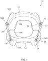
- this mouthpiece 10 includes maxillary dental appliance (a second dental appliance) 12 to be worn on the upper jaw teeth and mandibular dental appliance (a first dental appliance) 14 to be worn on the lower jaw teeth as shown in FIG. 1 .
- Maxillary dental appliance 12 and mandibular dental appliance 14 may be made of, but not limited to, acrylic resin, for example.
- maxillary dental appliance 12 and mandibular dental appliance 14 may be made of a single hard material having a flexural modulus of 2,000 MPa or more and 3,000 MPa or less or combination of a soft material with 10 MPa or more and 300 MPa or lower and a hard material with 1,000 MPa or more and 3,000 MPa or less.
- Maxillary dental appliance 12 and mandibular dental appliance 14 may also be made of relatively soft material having a tensile strength of 150 N or more and less than 2,000 N, particularly 150 N or more and 500 N or less. In that case, maxillary dental appliance 12 and mandibular dental appliance 14 of mouthpiece 10 would have high conformity to the teeth when they are worn.
- the tensile strength refers to the strength at which a mouthpiece (3-mm thick) fabricated with a Nissin standard model tears in a tensile testing conducted in the molar direction (backward on the row of teeth) with a hole 1.5 mm in diameter bored at the sixth tooth in the maxillary dental appliance or mandibular dental appliance of the mouthpiece.
- Materials with a tensile strength of 150 N or more and less than 2,000 N include, for example, olefin-based resins, polyester-based resin, urethane-based resin, polyamide-based resin, and acrylic rubber resin, where the olefin-based resin is preferable inter alia.
- An olefin-based resin is a polymer made by homopolymerization of olefin or a copolymer of olefin and another monomer.
- Olefin with a carbon number of 2 to 6 containing ethylene, propylene, butene, methylpentene, and hexene is preferred.
- the other monomer may be vinyl acetate, for example.
- the olefin-based resin is polyethylene (PE), polyethylene-based resin, polypropylene (PP), polypropylene-based resin, and ethylene-vinyl acetate copolymer (EVA), for example, and more preferably, is polyethylene (PE), polyethylene-based resin, polypropylene (PP), or polypropylene-based resin.
- PE polyethylene
- PP polypropylene
- EVA ethylene-vinyl acetate copolymer
- Polyester-based resin is a polycondensate of polyvalent carboxylic acid (dicarboxylic acid) and polyalcohol (diol), for example, polyethyleneterephthalate (PET).
- Urethane-based resin is a polycondensate of a compound having an isocyanate group and a compound having a hydroxy group, for example, is thermoplastic polyurethane (TPU).
- Polyamide-based resin is a polymer formed by binding of many monomers by amide bond, for example, nylon, para-amide, and meta-amide.
- Acrylic rubber resin consists mainly of acrylic rubber, for example, is a block copolymer of methyl methacrylate and butyl acrylate.
- Material with a tensile strength of 150 N or more and less than 2,000 N may be a commercially available material, such as F327, a polypropylene resin manufactured by Prime Polymer Co., Ltd.
- Maxillary dental appliance 12 is provided with upper attaching part (a second attaching part) 16 on outer wall surface 12A so as to project from outer wall surface 12A at the back on each of the right and left sides (the sixth or seventh tooth in FIG. 1 ), when seen from the center of the row of teeth.
- Upper attaching part 16 is made of metal.
- mandibular dental appliance 14 is provided with lower attaching part (a first attaching part) 18 on outer wall surface 14A so as to project from outer wall surface 14A at the back on each of the right and left sides (the third or fourth tooth in FIG. 1 ), when seen from the center of the row of teeth.
- Lower attaching part 18 is made of metal.
- Upper attaching part 16 has columnar shaft 20 with one end fixed to outer wall surface 12A of maxillary dental appliance 12, and a flange 22 provided at the other end (a tip) of shaft 20.
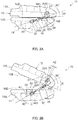
- Flange 22 is of a corner-rounded rectangular shape with a major axis and a minor axis. As shown in FIG. 2A , the angle of the major axis of flange 22 relative to opposing surface 12B of maxillary dental appliance 12 which faces mandibular dental appliance 14 is about 90 degrees.
- lower attaching part 18 has columnar shaft 24 with one end fixed on outer wall surface 14A of mandibular dental appliance 14, and flange 26 of a corner-rounded rectangular shape provided at the tip of shaft 24.
- the angle of the major axis of flange 26 relative to opposing surface 14B of mandibular dental appliance 14 which faces maxillary dental appliance 12 is about 90 degrees.
- the angle of the major axis of flange 22 relative to opposing surface 12B and the angle of the major axis of flange 26 relative to opposing surface 14B may both be any angle outside the range of 10 to 60 degrees.
- Right upper attaching part 16 and right lower attaching part 18 have dental coupling member 28 made of metal attached thereon, while left upper attaching part 16 and left lower attaching part 18 have another dental coupling member 28 made of metal attached thereon.
- Dental coupling member 28 is rotatable about the axis of upper attaching part 16 when coupled to upper attaching part 16 and is also rotatable about the axis of lower attaching part 18 when coupled to lower attaching part 18.
- Dental coupling member 28 couples maxillary dental appliance 12 and mandibular dental appliance 14 with each other in an openable and closable manner and positions them so that mandibular dental appliance 14 does not move backward on the row of teeth relative to maxillary dental appliance 12.
- mouthpiece 10 when seen from the center of the row of teeth, upper attaching part 16 is situated on the back side with respect to lower attaching part 18 (on the back teeth side). That is, mouthpiece 10 is of Push type: it pushes mandibular dental appliance 14 (the lower jaw) frontward by means of dental coupling member 28 when mouthpiece 10 is worn.
- FIGS. 3A and 3B show an exemplary dental coupling member 28 for attachment to mouthpiece 10.
- Dental coupling member 28 has cylinder 29, which is an elongated body.
- cylinder 29 has tubular outer tube 30 being open at the end on first-orientation end region 30P side and at the end on second-orientation end region 30Q side, and tubular inner tube 32 slidably inserted in outer tube 30.
- Dental coupling member 28 further has rod 34, which is an elongated body to be inserted into inner tube 32 (cylinder 29).
- Long hole 30A is formed in the outer peripheral surface of outer tube 30 between first-orientation end region 30P and second-orientation end region 30Q along the axial direction.
- upper eyelet 30B of a corner-rounded rectangular shape to be engaged with flange 22 of upper attaching part 16 in FIG. 1 is formed.
- Upper eyelet 30B is of a similar shape to flange 22 (a corner-rounded rectangular shape with a longer diameter and a shorter diameter) and is located such that the direction of the longer diameter is the same as the longitudinal direction of dental coupling member 28 (the axial direction of outer tube 30).
- Upper eyelet 30B is formed with a size slightly larger than flange 22. Specifically, a length L1 of the longer diameter of upper eyelet 30B is greater than a length R1 of the major axis of flange 22 shown in FIG. 2B .
- a length L2 of the shorter diameter of upper eyelet 30B is greater than a length R2 of the minor axis of flange 22 shown in FIG. 2B and is shorter than the length R1 of the major axis of flange 22. This allows upper eyelet 30B to be attached to and detached from flange 22 only at a position where the direction of its longer diameter is aligned with the direction of the major axis of flange 22.
- Housed part 32A which is a protrusion, is formed so as to project on the outer peripheral surface of second-orientation end region 32Q of inner tube 32.
- Housed part 32A has a diameter smaller than the width of long hole 30A of outer tube 30, and is slidably inserted into and housed in long hole 30A such that housed part 32A also slides in long hole 30A upon sliding of inner tube 32 in outer tube 30.
- female screw part 32B is formed on the inner peripheral surface of first-orientation end region 32P of inner tube 32.
- opening 32C is formed on the outer peripheral surface of inner tube 32 near first-orientation end region 32P.
- male screw part 34A to be screwed with female screw part 32B of inner tube 32 is formed.
- Non-threaded part 36 is provided as a part of male screw part 34A along the axial direction, with scale 36A formed on non-threaded part 36.
- lower eyelet 34B of a corner-rounded rectangular shape to be engaged with flange 26 of lower attaching part 18 in FIG. 1 is formed on an axial center RA of rod 34.
- Lower eyelet 34B is of a similar shape to flange 26 (a corner-rounded rectangular shape with a longer diameter and a shorter diameter), with the direction of its longer diameter being the same as the longitudinal direction of dental coupling member 28 (the axial direction of rod 34).
- lower eyelet 34B is formed with a size slightly larger than flange 26. Specifically, the length L1 of the longer diameter of lower eyelet 34B is longer than the length R1 of the major axis of flange 26 shown in FIG. 2B .
- the length L2 of the shorter diameter of lower eyelet 34B is greater than the length R2 of the minor axis of flange 26 shown in FIG. 2B and is shorter than the length R1 of the major axis of flange 26. This allows lower eyelet 34B to be attached to and detached from flange 26 only at a position where the direction of its longer diameter is aligned with the direction of the major axis of flange 26.
- the length of dental coupling member 28 is steplessly adjusted by rotating rod 34 about the axis to adjust the amount of screwing of male screw part 34A into female screw part 32B of inner tube 32.
- Dental coupling member 28 also follows the motion of maxillary dental appliance 12 and mandibular dental appliance 14 by the sliding of inner tube 32 in outer tube 30.
- exemplary mouthpiece 10 is attached to a row of teeth by upper eyelet 30B catching on shaft 20 and lower eyelet 34B catching on shaft 24 such that maxillary dental appliance 12 and mandibular dental appliance 14 are coupled to each other by dental coupling member 28.
- the position of mandibular dental appliance 14 is adjusted so that mandibular dental appliance 14 does not lie on the back side on the row of teeth with respect to maxillary dental appliance 12.
- Mouthpiece 10 allows scale 36A formed on non-threaded part 36 of rod 34 to be viewed from opening 32C of inner tube 32.
- the amount of screwing of male screw part 34A can be checked by viewing scale 36A formed on non-threaded part 36 of rod 34 from opening 32C of inner tube 32.
- mouthpiece 10 limits the backward movement of mandibular dental appliance 14 on the row of teeth (to the right side in FIG. 3A ) by the abutment of housed part 32A of inner tube 32 against the upper end (the right end in FIG. 3A ) of long hole 30A in outer tube 30, as shown in FIG. 2A .
- an attachment angle M of dental coupling member 28, namely the angle of the longer diameter of upper eyelet 30B relative to opposing surface 12B of maxillary dental appliance 12 and the angle of the longer diameter of lower eyelet 34B relative to opposing surface 14B of mandibular dental appliance 14, is about 10 degrees.
- the angle of the major axis of flange 22, 26 relative to opposing surface 12B or opposing surface 14B is about 90 degrees, the angle of the major axis of flange 22, 26 does not coincide with the angle of the longer diameter of upper eyelet 30B and lower eyelet 34B, respectively.
- an attachment angle N of dental coupling member 28, namely the angle of the longer diameter of upper eyelet 30B relative to opposing surface 12B of maxillary dental appliance 12 and the angle of the longer diameter of lower eyelet 34B relative to opposing surface 14B of mandibular dental appliance 14, is about 40 to 60 degrees, as shown in FIG. 2B .
- the angle of the major axis of flange 22, 26 relative to opposing surface 12B or opposing surface 14B is about 90 degrees, the angle of the major axis of flange 22, 26 does not coincide with the angle of the longer diameter of upper eyelet 30B and lower eyelet 34B, respectively.
- dental coupling member 28 follows the motion of maxillary dental appliance 12 and mandibular dental appliance 14 by the sliding of inner tube 32 in outer tube 30. In doing so, housed part 32A of inner tube 32 moves downward from the upper end of long hole 30A of outer tube 30 (to the left side in FIG. 3B ) to abut against the lower end of long hole 30A (the left end in FIG. 3B ).
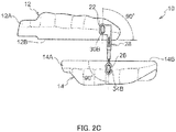
- mouthpiece 10 is first removed from the row of teeth. Then, as shown in FIG. 2C , maxillary dental appliance 12 and mandibular dental appliance 14 are separated from each other substantially in the horizontal direction so that the attachment angle of dental coupling member 28 becomes about 90 degrees.
- the angle of the longer diameter of upper eyelet 30B relative to opposing surface 12B of maxillary dental appliance 12 as well as the angle of the longer diameter of lower eyelet 34B relative to opposing surface 14B of mandibular dental appliance 14 also become about 90 degrees.
- dental coupling member 28 can be removed from upper attaching part 16 and lower attaching part 18.
- Mouthpiece 10 allows the amount of screwing of male screw part 34A into female screw part 32B to be adjusted by rotation of rod 34 about the axis.
- rod 34 when lower eyelet 34B is engaged with flange 26, it is substantially impossible for rod 34 to rotate about the axis. This can prevent rod 34 from rotating to cause an unnecessary change in the length of dental coupling member 28 when mouthpiece 10 is worn on the row of teeth.
- Mouthpiece 10 also limits the sliding of inner tube 32 in both axial directions by making housed part 32A of inner tube 32 provided in outer tube 30 abut against the opposite ends of long hole 30A formed between the opposite axial ends of outer tube 30.
- Housed part 32A of inner tube 32 moves within long hole 30A of outer tube 30 in the axial direction. This can restrain inner tube 32 from rotating about the axis relative to outer tube 30 when it slides in outer tube 30.
- Mouthpiece 10 also has flanges 22, 26 of a corner-rounded rectangular shape at upper attaching part 16 and lower attaching part 18, with upper eyelet 30B and lower eyelet 34B of dental coupling member 28 being of a corner-rounded rectangular shape slightly larger than flange 22, 26 (a similar shape).
- angle of the major axis of flange 22, 26 relative to opposing surface 12B, 14B of maxillary dental appliance 12 or mandibular dental appliance 14 is about 90 degrees, which falls outside the attachment angle of dental coupling member 28.
- upper eyelet 30B and lower eyelet 34B are restrained to an extent that makes attachment and detachment to/from flange 22, 26 substantially impossible, allowing the coupled state between maxillary dental appliance 12 and mandibular dental appliance 14 to be maintained.
- upper eyelet 30B and lower eyelet 34B can be easily attached and detached to/from flange 22, 26. That is, just by changing the attachment angle relative to mouthpiece 10, dental coupling member 28 can be switched between a state facilitating attachment/detachment and a state restraining attachment/detachment.
- maxillary dental appliance 12 and mandibular dental appliance 14 can be easily decoupled for maintenance or replacement, compared to a configuration with upper eyelet 30B and lower eyelet 34B being bonded, screwed or the like with flange 22, 26.
- upper eyelet 30B and lower eyelet 34B have a corner-rounded rectangular shape, space is formed between shaft 20 of upper attaching part 16 and upper eyelet 30B and between shaft 24 of lower attaching part 18 and lower eyelet 34B when mouthpiece 10 is worn on the row of teeth. Sliding of shaft 20, 24 in this space enables dental coupling member 28 to follow the motion of maxillary dental appliance 12 and mandibular dental appliance 14 to an increased degree.
- Embodiments 1 through 19 as variations of the dental coupling member are described.
- Embodiments 1 through 12 are examples of dental coupling members for restraining the loosening between the screwing part and the screwed part according to the first aspect of the present invention
- Embodiments 13 through 16 are embodiments that can be applied to any of Embodiments 1 through 12 in combination as further variations of these embodiments
- Embodiments 17 through 19 are examples of dental coupling members for limiting an excessive insertion of the insert into the outer tube with a simple structure according to the second aspect of the present invention.
- descriptions on features that overlap ones from previous embodiments and the associated operation or effect are omitted, and reference may be made as appropriate to the description of previous embodiments in which such features were described.
- either one or both of male screw part 34A and female screw part 32B is provided with a different-torque part that involves a different torque for screwing with the other of male screw part 34A and female screw part 32B so as to form a portion with larger frictional force, thus restraining the loosening of male screw part 34A relative to female screw part 32B even after torque has been released.
- the dental coupling member according to Embodiment 1 has rod 134 shown in FIGS. 4A and 4B .
- gap part 136 is formed in rod 134 on second-orientation end region 134Q side.
- Gap part 136 partially segments second-orientation end region 134Q of male screw part 134A in the direction orthogonal to the axial center RA (in the direction from the viewer's side into the page in FIG. 4B ).
- gap part 136 is a substantially cuboid slit that passes through the axial center RA of rod 134.
- gap part 136 is a slit extending from the axial center RA of rod 134 toward the outer periphery so as to segment male screw part 134A (into two). Consequently, in rod 134, second-orientation end region 134Q of male screw part 134A is segmented by gap part 136 into two parts that are substantially symmetric in the vertical direction in FIG. 4B .
- the two segment parts are substantially rotationally symmetric (substantially two-fold symmetric) by an angle of 180 degrees about the axial center RA.
- the length L1 (depth) of gap part 136 is such a length that reaches an intermediate position on male screw part 134A in the direction of axial center RA.
- male screw part 134A In this vertically segmented portion of male screw part 134A, increased diameter part 134E with an outer diameter increased by gap part 136 is formed.
- An outer diameter D1 of increased diameter part 134E (the vertical dimension in FIG. 4B ) gradually increases toward second-orientation end region 134Q side.
- the portion where gap part 136 is not formed is constant diameter part 134F having a constant outer diameter D2. That is, male screw part 134A includes constant diameter part 134F having the constant outer diameter D2 and increased diameter part 134E having the outer diameter D1 greater than that of constant diameter part 134F.
- Increased diameter part 134E is an example of "large diameter part”
- constant diameter part 134F is an example of "small diameter part”
- increased diameter part 134E and constant diameter part 134F are examples of "different-torque part” and of "different-diameter part”.
- Increased diameter part 134E can be formed, for example, by forming gap part 136 during the manufacture of rod 134 and then slightly spreading the vertically segmented portions away from each other. Due to the formation of gap part 136, increased diameter part 134E is elastically deformable in the direction toward the axial center RA of rod 134 (in the direction of arrow E1).
- the outer diameter D1 at the tip of increased diameter part 134E is sized to be screwed with female screw part 32B of inner tube 32 with increased diameter part 134E elastically deformed in such a manner.
- constant diameter part 134F has the outer diameter D2 smaller than that of increased diameter part 134E as mentioned above but is sized to be screwed with female screw part 32B of inner tube 32.
- male screw part 134A When male screw part 134A is screwed with female screw part 32B, male screw part 134A makes stronger contact with female screw part 32B and generates larger frictional force against female screw part 32B during rotation in increased diameter part 134E than in constant diameter part 134F. That is, large torque is required for rotation during screwing with female screw part 32B compared to a male screw part of a structure without increased diameter part 134E.
- Inner tube 32 has a constant inner diameter in female screw part 32B. In other words, there is no portion where the inner diameter of the inner peripheral surface of inner tube 32 changes. Thus, inner tube 32 is of a shape that facilitates the formation of female screw part 32B.
- male screw part 134A includes increased diameter part 134E and constant diameter part 134F. Due to the formation of increased diameter part 134E, large torque is required when male screw part 134A is threaded into and rotated in female screw part 32B, compared with a rod having a male screw part with no formation of increased diameter part 134E. Accordingly, male screw part 134A is restrained from becoming loose relative to female screw part 32B even after the amount of screwing of male screw part 134A is adjusted, that is, after torque on rod 134 has been released. This restrains a shift in the relative position between rod 134 and inner tube 32. In turn, the position of mandibular dental appliance 14 relative to maxillary dental appliance 12 can be reliably maintained at the adjusted position as well.
- increased diameter part 134E or the larger diameter portion tends to make strong contact with female screw part 32B of cylinder 29 and causes large frictional force compared to constant diameter part 134F or the smaller diameter portion, so that loosening of male screw part 134A relative to female screw part 32B can be restrained.
- male screw part 134A is screwed with female screw part 32B also at constant diameter part 134F, force that acts in the state of being screwed with female screw part 32B is distributed throughout male screw part 134A, which can further restrain the loosening of male screw part 134A relative to female screw part 32B.
- increased diameter part 134E can elastically deform inward in the radial direction of rod 134 such that gap part 136 becomes smaller. That is, as increased diameter part 134E is screwed with female screw part 32B while undergoing elastic deformation, load can be made to act from increased diameter part 134E to female screw part 32B while restraining the abrasion of increased diameter part 134E.
- gap part 136 is easy to form.
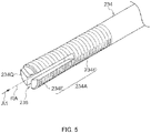
- the dental coupling member according to Embodiment 2 has rod 234 shown in FIG. 5 .
- This rod 234 has gap part 236 formed in second-orientation end region 234Q of male screw part 234A.
- gap part 236 is formed in three parts toward the outer periphery side radially about the axial center RA of rod 234.
- gap part 236 is a slit extending toward the outer periphery from the axial center RA of rod 234 so as to segment male screw part 234A (into three). That is, a portion of male screw part 234A is segmented into three parts in the axial direction about the axial center RA.
- the three segment parts are substantially rotationally symmetric (substantially three-fold symmetric) by an angle of 120 degrees about the axial center RA.
- male screw part 234A includes increased diameter part 234E and constant diameter part 234F.
- inner tube 32 also has a constant inner diameter in female screw part 32B in Embodiment 2.
- large torque is required when male screw part 234A is threaded into and rotated in female screw part 32B, compared to a rod having a male screw part with no formation of increased diameter part 234E. After the amount of screwing of male screw part 234A is adjusted, male screw part 234A is restrained from becoming loose relative to female screw part 32B.
- Increased diameter part 234E is an example of "large diameter part”
- constant diameter part 234F is an example of "small diameter part”
- increased diameter part 234E and constant diameter part 234F are examples of "different-torque part” and of "different-diameter part”.
- Embodiment 2 three segment parts are formed in second-orientation end region 234Q of male screw part 234A of rod 234, providing more segment parts than in Embodiment 1, in which two segment parts are formed.
- Such an increase in the number of segment parts results in a smaller size of each segment part, which makes it easier to bend the segment parts radially outward and thus facilitates the formation of increased diameter part 234E.
- a structure with a small number of segment parts facilitates processing or shaping of the rod because less gap parts are required.
- the number of segment regions in Embodiment 2 may be any number greater than two, such as four (substantially four-fold symmetric) or six (substantially six-fold symmetric).
- gap part 236 may be a slit of any form that segments second-orientation end region 234Q of male screw part 234A of rod 234 into substantially rotationally symmetric shapes of substantially three-fold or higher rotational symmetry.
- the dental coupling member according to Embodiment 3 has rod 334 shown in FIG. 6 .
- This rod 334 has gap part 336 formed in second-orientation end region 334Q.
- Gap part 336 is a slit which is formed at a position offset from the axial center RA of rod 334, avoiding the axial center RA.
- increased diameter part 334E is segmented into shapes that are not rotationally symmetric, including a relatively small segment (small segment 334G) and a relatively large segment (large segment 334H), as seen from second-orientation end region 334Q side (in the direction of arrow A1).
- gap part 336 is a slit that segments male screw part 334A into a portion including the axial center RA of rod 334 and a portion not including the axial center RA of rod 334 (into two).
- Small segment 334G is easier to deform radially outward (in the direction opposite to arrow E1) than large segment 334H. Accordingly, increased diameter part 334E of rod 334 is virtually formed by the radially outward spreading of small segment 334G.
- large segment 334H may also assume a shape spreading outward radially.
- male screw part 334A includes increased diameter part 334E and constant diameter part 334F.
- inner tube 32 has a constant inner diameter in female screw part 32B also in Embodiment 3. Accordingly, large torque is required when male screw part 334A is threaded into and rotated in female screw part 32B, compared to a rod having a male screw part with no formation of increased diameter part 334E. After the amount of screwing of male screw part 334A is adjusted, male screw part 334A is restrained from becoming loose relative to female screw part 32B.
- Increased diameter part 334E is an example of "large diameter part”
- constant diameter part 334F is an example of "small diameter part”
- increased diameter part 334E and constant diameter part 334F are examples of "different-torque part” and of "different-diameter part”.
- small segment 334G and large segment 334H are formed, with small segment 334G being easier to deform radially outward than large segment 334H. That is, elastic adjustment of the outer diameter D1 (not shown in FIG. 6 , see FIG. 4B ) at increased diameter part 334E of rod 334 is facilitated compared to a structure having segments 34D of a substantially rotationally symmetric shape, such as in Embodiment 1, and it is also possible to adjust frictional force when screwing increased diameter part 334E with female screw part 32B.
- second-orientation end region 334Q of male screw part 334A of rod 334 is segmented into two segment regions in FIG. 6 , it may be segmented into three or more segment regions different in shape or size.
- the dental coupling member according to Embodiment 4 has rod 434 shown in FIGS. 7A and 7B .
- This rod 434 has gap part 436 formed in second-orientation end region 434Q.
- Gap part 436 is a slit formed in a shape that has a width changing in the depth direction (the direction from the second-orientation end region side of male screw part 434 toward the first-orientation end region side) and is substantially rotationally symmetric at a position passing through the axial center RA of rod 434 and about the axial center RA.
- male screw part 434A includes increased diameter part 434E and constant diameter part 434F.
- inner tube 32 also has a constant inner diameter in female screw part 32B in Embodiment 4. Accordingly, large torque is required when male screw part 434A is threaded into and rotated in female screw part 32B, compared to a rod having a male screw part with no formation of increased diameter part 434E. After the amount of screwing of male screw part 434A is adjusted, male screw part 434A is restrained from becoming loose relative to female screw part 32B.
- the range having the constant outer diameter D1 as the increased diameter part of rod 434 is long in the axial direction of rod 434.
- large frictional force can be generated by allowing the increased diameter part to make contact with female screw part 32B over a wide range.
- second-orientation end region 434Q of male screw part 434A of rod 434 is segmented into two segment regions in FIGS. 7A and 7B , it may be segmented into three or more segment regions.
- the dental coupling member according to Embodiment 5 has rod 534 shown in FIGS. 8A and 8B .
- rod 534 has increased diameter part 534E of a truncated cone shape formed in a portion of male screw part 534A, in particular in a portion with a predetermined length L1 in second-orientation end region 534Q of male screw part 534A.
- the portion on first-orientation end region 34P (see FIGS. 3A and 3B ) side is a portion with no formation of increased diameter part 534E and is constant diameter part 534F with an outer diameter D2 smaller than that of increased diameter part 534E.
- the outer diameter D2 of constant diameter part 534F is constant in the axial direction of rod 534.
- the outer diameter D1 of increased diameter part 534E increases from the portion continuous with constant diameter part 534F toward second-orientation end region 534Q side.
- the outer diameter D1 of increased diameter part 534E is then at its maximum at the end on second-orientation end region 534Q side.
- outer diameter D1 linearly increases toward second-orientation end region 534Q side in the example shown in FIGS. 8A and 8B
- the shape of increased diameter part 534E is not limited to such a shape with outer diameter D1 increasing linearly.
- male screw part 534A is formed during the manufacture of rod 534, for example, the length L1 portion on second-orientation end region 534Q side is formed such that the outer diameter increases toward the end on second-orientation end region 534Q side. Then, by forming male screw part 534A in a predetermined range including the length L1 portion, male screw part 534A including increased diameter part 534E can be formed on rod 534.
- Constant diameter part 534F and increased diameter part 534E are of circular shapes that are substantially rotationally symmetric relative to the axis RA and centered at the axis RA.
- the outer diameter D2 of constant diameter part 534F is sized to be screwed with female screw part 32B.
- the outer diameter D1 of increased diameter part 534E is sized to be screwed with female screw part 32B even in the portion with the largest outer diameter.
- the radial clearance between male screw part 534A and female screw part 32B is constant between constant diameter part 534F and female screw part 32B but gradually becomes narrower between increased diameter part 534E and female screw part 32B toward second-orientation end region 534Q side.
- male screw part 534A When male screw part 534A is screwed with female screw part 32B, male screw part 534A makes stronger contact with female screw part 32B and generates larger frictional force against female screw part 32B during rotation in increased diameter part 534E than in constant diameter part 534F. That is, large torque is required for rotation during screwing with female screw part 32B compared to a male screw part of a structure without increased diameter part 534E.
- Inner tube 32 has a constant inner diameter in female screw part 32B. In other words, there is no portion where the inner diameter of the inner peripheral surface of inner tube 32 changes. Thus, inner tube 32 is of a shape that facilitates the formation of female screw part 32B.
- Rod 534 according to the variation shown in FIG. 8C may be used in Embodiment 5.
- the outer diameter D1 of male screw part 534A gradually increases toward the end on second-orientation end region 534Q side substantially over the entire range in which male screw part 534A is formed.
- screwing large-diameter part 534E an example of the different-diameter part, is formed substantially throughout male screw part 534A.
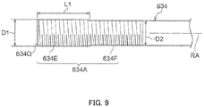
- the dental coupling member according to Embodiment 6 has rod 634 shown in FIG. 9 .
- This rod 634 has increased diameter part 634E of a cylindrical shape, formed in second-orientation end region 634Q of male screw part 634A.
- This increased diameter part 634E is of a shape that has a constant outer diameter D1 over the range of a certain length L1 from the end on second-orientation end region 634Q side.
- Increased diameter part 634E and constant diameter part 634F are examples of "different-torque part" and of "different-diameter part”.
- male screw part 634A includes increased diameter part 634E and constant diameter part 634F.
- large torque is required when male screw part 634A is threaded into and rotated in female screw part 32B, compared to a rod having a male screw part with no formation of increased diameter part 634E. After the amount of screwing of male screw part 634A is adjusted, male screw part 634A is restrained from becoming loose relative to female screw part 32B.
- increased diameter part 634E has the constant outer diameter D1 and spans a certain length L1 in the axial direction. Since the portion that makes strong contact with female screw part 32B spreads in the axial direction in male screw part 634A, namely the screwing part, a portion that generates large frictional force when screwing male screw part 634A and female screw part 32B together can be secured to be wide, stabilizing the torque required for rotation when male screw part 634A is screwed with female screw part 32B.
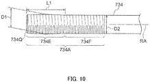
- the dental coupling member according to Embodiment 7 has rod 734 shown in FIG. 10 .
- This rod 734 has increased diameter part 734E of a barrel shape formed in second-orientation end region 734Q of male screw part 734A.
- Increased diameter part 734E is formed in the range of a certain length L1 from the end on the second-orientation end region 734Q side.
- increased diameter part 734E is shaped such that outer diameter D1 is at its maximum at the center of this range of length L1 and outer diameter D1 decreases as it goes away from the center.
- Increased diameter part 734E and constant diameter part 734F are examples of "different-torque part" and of "different-diameter part”.
- male screw part 734A includes increased diameter part 734E and constant diameter part 734F.
- large torque is required when male screw part 734A is threaded into and rotated in female screw part 32B, compared to a rod having a male screw part with no formation of increased diameter part 734E. After the amount of screwing of male screw part 734A is adjusted, male screw part 734A is restrained from becoming loose relative to female screw part 32B.
- increased diameter part 734E is shaped such that it tapers from the center of increased diameter part 734E in the axial direction toward the end on second-orientation end region 734Q side. Accordingly, male screw part 734A is easy to screw with female screw part 32B in an early stage of screwing male screw part 734A with female screw part 32B.
- the dental coupling member according to Embodiment 8 has inner tube 832 shown in FIG. 11A .
- This inner tube 832 has inner-diameter reduced part 832E formed in female screw part 832B such that female screw part 832B is a different-diameter part.
- female screw part 832B has inner-diameter reduced part 832E with an inner diameter D3 that decreases from the center in the axial direction toward the end on first-orientation end region 832P side.
- female screw part 832B has a constant inner diameter D4 in the portion where inner-diameter reduced part 832E is not formed.
- the male screw part in Embodiment 8 has a constant outer diameter in the axial direction of the rod.
- such a portion with decreasing inner diameter D3 within female screw part 832B is inner-diameter reduced part 832E.
- the clearance between female screw part 832B and the male screw part of the rod is constant in the portion where inner-diameter reduced part 832E is not formed, but it gradually becomes narrower toward the end on first-orientation end region 832P side of inner tube 832 in the portion where inner-diameter reduced part 832E is formed.
- 11A female screw part 832B is shaped such that its inner diameter decreases from the center in the axial direction toward the end on first-orientation end region 832P side, it may have a barrel shape with inner diameter D3 being at its maximum in the center of the range of length L1 and decreasing as it goes away from the center.
- Inner tube 842 according to a second variation shown in FIG. 11B may be used in Embodiment 8.
- inner-diameter reduced part 842E is of a shape having a constant inner diameter D3 over the range of a certain length L1 from the end on first-orientation end region 842P side.
- inner-diameter reduced part 842E spans a certain length L1 in the axial direction. Since the portion that makes strong contact with the male screw part spreads in the axial direction in female screw part 842B, the torque required for rotation when the male screw part is screwed with female screw part 842B is stabilized.
- the dental coupling member according to Embodiment 9 has rod 934 shown in FIGS. 12A and 12B .
- rod 934 has screwing small-pitch part 934G formed in the portion where male screw part 934A is formed, in particular a portion with a predetermined length L1 in second-orientation end region 934Q.
- a portion on first-orientation end region 34P (see FIGS. 3A and 3B ) side is a portion with no formation of screwing small-pitch part 934G and is screwing large-pitch part 934H having pitch P2 greater than the pitch of screwing small-pitch part 934G.
- the pitch P2 of screwing large-pitch part 934H is constant in the axial direction of rod 934 and is equal to the pitch of female screw part 32B.
- the pitch P1 of screwing small-pitch part 934G decreases from the portion continuous with screwing large-pitch part 934H toward the end on second-orientation end region 934Q side.
- the pitch P1 of screwing small-pitch part 934G is then at its minimum at the end on second-orientation end region 934Q side.
- the shape of screwing small-pitch part 934G is not limited to such a shape with pitch P1 decreasing linearly.
- a male screw with pitch P1 is formed in a predetermined range including the length L1 portion, for example, at a stage of forming male screw part 934A during the manufacture of rod 934. Then, by forming a male screw with pitch P2 in the range of male screw part 934A excluding the predetermined range, male screw part 934A including screwing small-pitch part 934G can be formed on rod 934.
- Screwing large-pitch part 934H and screwing small-pitch part 934G are substantially symmetric in the circumferential direction, that is, are circular shapes centered at axis RA when seen in the direction of axis RA (in the direction of arrow A1).
- the pitch P2 of screwing large-pitch part 934H is sized to be screwed with female screw part 32B.
- the pitch P1 of screwing small-pitch part 934G is sized to be screwed with female screw part 32B even in the portion with the smallest pitch.
- the pitch difference between male screw part 934A and female screw part 32B is constant between screwing large-pitch part 934H and female screw part 32B (is virtually zero, for example), but gradually increases between screwing small-pitch part 934G and female screw part 32B toward the end on second-orientation end region 934Q side.
- Screwing large-pitch part 934H and screwing small-pitch part 934G are examples of "different-torque part” and of "different-pitch part ".
- male screw part 934A When male screw part 934A is screwed with female screw part 32B, male screw part 934A makes stronger contact with female screw part 32B and generates larger frictional force against female screw part 32B during rotation in screwing small-pitch part 934G than in screwing large-pitch part 934H. That is, large torque is required for rotation during screwing with female screw part 32B compared to a male screw part of a structure without screwing small-pitch part 934G.
- Inner tube 32 has a constant inner diameter in female screw part 32B. In other words, there is no portion where the inner diameter of the inner peripheral surface of inner tube 32 changes. Thus, inner tube 32 is of a shape that facilitates the formation of female screw part 32B.
- Rod 934 according to the variation shown in FIG. 12C may be used in Embodiment 9.
- the pitch P1 of male screw part 934A gradually degreases toward the end on second-orientation end region 934Q side substantially in the entire range in which male screw part 934A is formed.
- screwing small-pitch part 934G an example of the different-pitch part, is formed substantially throughout male screw part 934A.
- the dental coupling member according to Embodiment 10 has rod 1034 shown in FIG. 13 .
- This rod 1034 has screwing small-pitch part 1034G formed in second-orientation end region 1034Q of male screw part 1034A.
- This screwing small-pitch part 1034G is of a shape having a constant pitch P1 over the range of a certain length L1 from the end on second-orientation end region 1034Q side.
- male screw part 1034A includes screwing small-pitch part 1034G and screwing large-pitch part 1034H.
- large torque is required when male screw part 1034A is threaded into and rotated in female screw part 32B, compared to a rod having a male screw part with no formation of screwing small-pitch part 1034G. After the amount of screwing of male screw part 1034A is adjusted, male screw part 1034A is restrained from becoming loose relative to female screw part 32B.
- screwing small-pitch part 1034G has a constant pitch P1 and spans a certain length L1 in the axial direction. Since the portion that makes strong contact with female screw part spreads in the axial direction in male screw part 1034A, namely the screwing part, the torque required for rotation when male screw part 1034A is screwed with female screw part is stabilized.
- the dental coupling member according to Embodiment 11 has rod 1134 shown in FIG. 14 .
- This rod 1134 has screwing small-pitch part 1134G formed in second-orientation end region 1134Q of male screw part 1134A.
- Screwing small-pitch part 1134G is formed in the range of a certain length L1 from the end on second-orientation end region 1134Q side.
- rod 1134 is shaped such that pitch P1 is at its minimum at the center of this range of length L1 and pitch P1 increases as it goes away from the center.
- male screw part 1134A includes screwing small-pitch part 1134G and screwing large-pitch part 1134H.
- large torque is required when male screw part 1134A is threaded into and rotated in female screw part 32B, compared to a rod having a male screw part with no formation of screwing small-pitch part 1134G. After the amount of screwing of male screw part 1134A is adjusted, male screw part 1134A is restrained from becoming loose relative to female screw part 32B.
- rod 1134 is shaped such that the pitch increases from the center of screwing small-pitch part 1134G in the axial direction toward the end on the second-orientation end region 1134Q side.
- the pitch of male screw part 1134A is close to the pitch of female screw part. Accordingly, male screw part 1134A is easy to screw with female screw part 32B in an early stage of screwing male screw part 1134A with female screw part 32B.
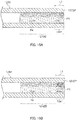
- the dental coupling member according to Embodiment 12 has inner tube 1232 shown in FIG. 15A .
- This inner tube 1232 has a different-pitch part formed in female screw part 1232B.
- pitch-reduced part 1232G is formed in the range of a certain length L1 from the end on first-orientation end region 1232P side, with pitch P3 decreasing from the center of female screw part 1232B in the axial direction toward the end on first-orientation end region 1232P side.
- female screw part 1232B has a constant pitch P4 in the portion where pitch-reduced part 1232G is not formed.
- the male screw part in Embodiment 12 has a constant pitch in the axial direction of the rod.
- pitch-reduced part 1232G such a portion of female screw part 1232B where pitch P3 decreases is pitch-reduced part 1232G.
- the pitch difference between female screw part 1232B and the male screw part of the rod is constant in the portion where pitch-reduced part 1232G is not formed, but it gradually increases toward the end on first-orientation end region 1232P side of inner tube 1232 in the portion where pitch-reduced part 1232G is formed.
- it may have a shape with the pitch increasing from the center in the axial direction toward the end on first-orientation end region 1232P side, or a barrel shape with the pitch being at its maximum in the center of the range of length L1 and the inner diameter decreasing as it goes away from the center.
- Inner tube 1242 according to a second variation shown in FIG. 15B may be used in Embodiment 12.
- Inner tube 1242 in the second variation is shaped such that pitch-reduced part 1232G has a constant pitch P3 over the range of a certain length L1 from the end on first-orientation end region 1242P side.
- pitch-reduced part 1232G spans a certain length L1 in the axial direction. Since the portion that makes strong contact with the male screw part spreads in the axial direction in female screw part 1242B, the torque required for rotation when the male screw part is screwed with female screw part 42B is stabilized.
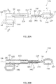
- Dental coupling member 1338 according to Embodiment 13 has tubular outer tube 40 being open both at the end on first-orientation end region 40P side and at the end on second-orientation end region 40Q side in the axial direction, tubular inner tube 42 slidably provided in outer tube 40, and rod 44 to be engaged with inner tube 42.
- Outer tube 40 has a pair of slits 40A formed at positions opposing each other along the axial direction of outer tube 40, between the end on first-orientation end region 40P side and the end on second-orientation end region 40Q side. In the vicinity of second-orientation end region 42Q of inner tube 42, columnar pin 46 has been attached so as to penetrate inner tube 42 in the radial direction.
- Slit 40A is an example of "limiting part”.
- the longer diameter of pin 46 is sized to be slightly smaller than the width of slit 40A in outer tube 40.
- the opposite ends of pin 46 in the longer diameter direction project from the outer peripheral surface of inner tube 42, and are slidably inserted in the pair of slits 40A, respectively.
- Dental coupling member 1338 is adjustable in length by sliding of inner tube 42 in outer tube 40. In doing so, the sliding of inner tube 42 in both axial directions is limited by abutment of pin 46 attached on inner tube 42 against the opposite ends of slits 40A in outer tube 40 (the right and left ends in FIG. 16 ).
- Embodiment 13 limits the sliding of inner tube 42 in outer tube 40 in both axial directions by making pin 46 attached on inner tube 42 abut against the opposite ends of slits 40A formed in outer tube 40. This can make dental coupling member 1338 compact in size compared to a configuration providing an inner tube like a nut outside of outer tube 40 or a configuration that makes inner tube 42 and/or rod 44 abut against an outer end of outer tube 40.
- inner tube 42 can be further restrained from rotating about the axis relative to outer tube 40 when inner tube 42 slides in outer tube 40.
- male screw part 44A includes an increased diameter part and a constant diameter part (see FIGS. 4A, 4B , 5 , 6 , 7A, 7B , 8A, 8B, 8C , 9 , 10 , 11A, and 11B ) or a screwing small-pitch part and a screwing large-pitch part ( FIGS. 12A, 12B , 13 , and 14 ).
- a screwing small-pitch part and a screwing large-pitch part FIGS. 12A, 12B , 13 , and 14 .
- Dental coupling member 1438 has tubular outer tube 50 being open both at the end on first-orientation end region 50P side and at the end on second-orientation end region side, tubular inner tube 52 slidably provided in outer tube 50, and rod 54 to be engaged with inner tube 52.
- Stopper 56A, 56B are of a cylindrical shape with a hollow part and are fixed on the inner peripheral surface of outer tube 50. Stoppers 56A and 56B are examples of "limiting part”.
- the length of inner tube 52 in the axial direction is shorter than the length between stoppers 56A and 56B, namely the length from the lower end of stopper 56A on the upper end side (the side of the left end in FIG. 17 ) to the upper end of stopper 56B on the lower end side (the side of the right end in FIG. 17 ), with inner tube 52 inserted between stoppers 56A and 56B in outer tube 50.
- Second-orientation end region 52P of inner tube 52 is abutting part 52B to abut against the lower end of stopper 56A, while first-orientation end region 52P of inner tube 52 is abutting part 52C to abut against the upper end of stopper 56B.
- lower eyelet 54B in the first-orientation end region is exposed from outer tube 50, with male screw part 54A in the second-orientation end region being inserted in outer tube 50 through the hollow part of stopper 56B and screwed with female screw part 52A of inner tube 52.
- Dental coupling member 1438 is adjustable in length by sliding of inner tube 52 between stoppers 56A and 56B in outer tube 50. In doing so, the sliding of inner tube 52 in both axial directions is limited by abutment of abutting parts 52B, 52C of inner tube 52 against stoppers 56A, 56B, respectively.
- Embodiment 14 limits the sliding of inner tube 52 within outer tube 50 in both axial directions by means of stopper 56A, 56B provided in outer tube 50 between the end on first-orientation end region 50P side and the end on second-orientation end region side. This can make dental coupling member 1438 compact in size compared to a configuration providing an inner tube or stoppers outside of outer tube 50.
- male screw part 54A includes an increased diameter part and a constant diameter part (see FIGS. 4A, 4B , 5 , 6 , 7A, 7B , 8A, 8B, 8C , 9 , 10 , 11A, and 11B ), or a screwing small-pitch part and a screwing large-pitch part ( FIGS. 12A, 12B , 13 , and 14 ).
- large torque is required when male screw part 54A is threaded into and rotated in the female screw part, and male screw part 54A is restrained from becoming loose relative to the female screw part.
- Dental coupling member 1538 has tubular outer tube 60 being open at the end on first-orientation end region 60P side and at the end on second-orientation end region 60Q side, tubular inner tube 62 slidably provided in outer tube 60, and rod 64 to be engaged with inner tube 62.
- decreased diameter parts 66A, 66B with a smaller inner diameter than the inner diameter of the other portion of outer tube 60 are formed between the end on first-orientation end region 60P side and the end on second-orientation end region 60Q side.
- Decreased diameter part 66A in second-orientation end region 60Q of outer tube 60 is formed by increasing the thickness of outer tube 60
- decreased diameter part 66B in first-orientation end region 60P of outer tube 60 is formed by crimping the lower end of outer tube 60.
- Decreased diameter parts 66A and 66B are examples of "limiting part".
- increased diameter part 68 with a larger outer diameter than the outer diameter of the other portion of inner tube 62 is integrally formed, and increased diameter part 68 of inner tube 62 can slide between decreased diameter parts 66A and 66B of outer tube 60.
- Insertion groove 68A is formed in the center of the end surface of increased diameter part 68 in second-orientation end region 62Q of inner tube 62. Insertion groove 68A is hexagonal, allowing insertion of a tool such as a hexagonal wrench.
- male screw part 64A formed in second-orientation end region 64Q has been screwed with female screw part 62A formed on the inner peripheral surface of inner tube 62.
- Dental coupling member 1538 is adjustable in length by sliding of inner tube 62 in outer tube 60. In doing so, the sliding of inner tube 62 in both axial directions is limited by abutment of increased diameter part 68 of inner tube 62 against decreased diameter part 66A or decreased diameter part 66B of outer tube 60.
- a hexagonal wrench is inserted into insertion groove 68A of increased diameter part 68 of inner tube 62 from the open end of outer tube 60 on second-orientation end region 60Q side. Then, the hexagonal wrench is rotated about the axis to rotate inner tube 62 about the axis, thereby adjusting the amount of screwing of male screw part 64A of rod 64 into female screw part 62A of inner tube 62.
- Embodiment 15 limits the sliding of inner tube 62 within outer tube 60 in both axial directions by means of decreased diameter parts 66A, 66B formed in outer tube 60 between the end on first-orientation end region 60P side and the end on second-orientation end region 60Q side.
- Embodiment 15 also allows the axial position of rod 64 relative to inner tube 62 to be adjusted by rotating inner tube 62 about the axis center RA, without rotation of rod 64 about the axis.
- the length of dental coupling member 1538 can be easily adjusted with lower eyelet 64B of rod 64 remaining engaged with flange 26 in FIG. 1 .
- male screw part 64A includes an increased diameter part and a constant diameter part (see FIGS. 4A, 4B , 5 , 6 , 7A, 7B , 8A, 8B, 8C , 9 , 10 , 11A, and 11B ), or a screwing small-pitch part and a screwing large-pitch part ( FIGS. 12A, 12B , 13 , and 14 ).
- large torque is required when male screw part 64A is threaded into and rotated in female screw part, and male screw part 64A is restrained from becoming loose relative to the female screw part.
- Dental coupling member 1628 has rod 34 and cylinder 1630.
- Cylinder 1630 is formed in a cylindrical shape, being open at the end on first-orientation end region 1630P side and at the end on second-orientation end region 1630Q side.
- female screw part 32B (not shown in FIG. 19 ; see FIG. 3B ) is formed, as with inner tube 32 in Embodiment 1.
- male screw part 34A includes increased diameter part 34E and constant diameter part 34F ( FIGS. 4A, 4B , 5 , 6 , 7A, 7B , 8A, 8B, 8C , 9 , 10 , 11A, and 11B ), or screwing small-pitch part 34G and screwing large-pitch part 34H ( FIGS. 12A, 12B , 13 , and 14 ).
- large torque is required when male screw part 34A is threaded into and rotated in female screw part 32B, and male screw part 34A is restrained from becoming loose relative to female screw part 32B.
- dental coupling member 1738 has outer tube 30 which is a tubular elongated body open at the end on first-orientation end region 30P side and at the end on second-orientation end region 30Q side, inner tube 32 which is a tubular elongated body slidably inserted in outer tube 30, and rod 34 which is an elongated body to be inserted into inner tube 32.
- Inner tube 32 is an example of "insert”.
- Protrusion 70 projects from the inner peripheral surface of outer tube 30.
- lug 30C projects at the longitudinal center of upper eyelet 30B.
- protrusion 70 is provided at a circumferential part of the inner peripheral surface of outer tube 30.
- Through hole 30R into which this lug 30C is inserted is formed in outer tube 30.
- Upper eyelet 30B is fixed to outer tube 30 by welding, bonding, crimping or the like.
- upper eyelet 30B is attached to upper attaching part 16 on the outer periphery side of outer tube 30 and is located penetrating through hole 30R such that lug 30C will be protrusion 70 facing the end surface of inner tube 32 on second-orientation end region 32Q side on the inner peripheral surface of outer tube 30.
- a height H1 of lug 30C is greater than the thickness of outer tube 30.
- the height H1 of protrusion 70 is a height that is not excessively great so that the tip of lug 30C lies off the axial center RA of the inner peripheral surface of outer tube 30, avoiding the axial center RA, as shown in FIG. 21 .
- the position of protrusion 70 in the axial direction is such a position that limits the movement of inner tube 32 within a predetermined range when it moves in outer tube 30 to second-orientation end region 30Q side by the contact of the end surface of inner tube 32 on second-orientation end region 32Q side with protrusion 70.
- the sliding of inner tube 32 to second-orientation end region 30Q side of outer tube 30 is limited within a predetermined range by the hitting of the end surface of inner tube 32 on second-orientation end region 32Q side against protrusion 70, as described later.
- the end surface of inner tube 32 on second-orientation end region 32Q side hits protrusion 70 at the position indicated by the two-dot chain line in FIG. 20B , thus limiting the sliding of inner tube 32 to the side of second-orientation end region 30Q of outer tube 30 to limit the backward movement of mandibular dental appliance 14 on the row of teeth (to the right side in FIG. 20A ).
- the sliding of inner tube 32 to the first-orientation end region side is limited within a predetermined range by the hitting of housed part 32A against the end of long hole 30A in outer tube 30 on first-orientation end region 30P side.
- the distance (center-to-center distance) between upper attaching part 16 and lower attaching part 18 is adjusted between about 18 mm and 50 mm with dental coupling member 1738.
- housed part 32A of inner tube 32 moves downward from the upper end of long hole 30A of outer tube 30 (to the left in FIG. 20B ), where it may or may not abut against the lower end of long hole 30A (the left end in FIG. 20B ).
- Embodiment 17 also limits the movement of inner tube 32 to second-orientation end region 30Q side of outer tube 30 in a predetermined range by the hitting of the end surface of inner tube 32 on second-orientation end region 32Q side against protrusion 70 projecting from the inner peripheral surface of outer tube 30.
- outer tube 30 is simple as there is no need to form the inner peripheral surface of outer tube 30 such that the inner diameter changes in two or more steps so as to form a wall and the like to be contacted by inner tube 32. Since no portion where the inner diameter changes is formed on the inner peripheral surface of the outer tube, the structure of outer tube 30 is simple. Outer tube 30 is then easy to shape and the manufacturing cost of outer tube 30 can be reduced.
- protrusion 70 is formed in a circumferential part of the inner peripheral surface of outer tube 30. Since protrusion 70 is not formed on the entire circumference, the inner diameter of the inner peripheral surface of outer tube 30 is constant and the structures of outer tube 30 and protrusion 70 are simple. In particular, since upper eyelet 30B is provided in a circumferential part of outer tube 30, a structure with protrusion 70 can be produced by forming lug 30C on this upper eyelet 30B.
- Protrusion 70 has a height H1 that does not reach the axial center RA inside outer tube 30. Thus, protrusion 70 will not hinder when a tool or the like is inserted from the second-orientation end region 30Q side of outer tube 30, facilitating the insertion of the tool or the like.
- Housed part 32A of inner tube 32 is housed such that it can move only in the axial direction within long hole 30A of outer tube 30. Thus, when inner tube 32 slides in outer tube 30, inner tube 32 can be restrained from rotating about the axis relative to outer tube 30.
- dental coupling member 1838 As shown in FIG. 22 , dental coupling member 1838 according to Embodiment 18 has tubular outer tube 60 open at the end on first-orientation end region 60P side and at the end on second-orientation end region 60Q side, tubular inner tube 62 slidably provided in outer tube 60, and rod 64 to be engaged with inner tube 62.
- first-orientation end region 60P of outer tube 60 decreased diameter part 66B having a smaller diameter than that of the other portion of outer tube 60 is formed.
- This decreased diameter part 66B is formed by crimping first-orientation end region 60P of outer tube 60, for example. While such a decreased diameter part 66B is formed in the first-orientation end region of outer tube 60, the inner diameter of the inner peripheral surface of outer tube 60 is constant. Decreased diameter part 66B is an example of "limiting part".
- increased diameter part 68 with a larger outer diameter than the outer diameter of the other portion of inner tube 62 is integrally formed.
- Increased diameter part 68 of inner tube 62 faces protrusion 70 of outer tube 60 on second-orientation end region 60Q side, and its end surface on first-orientation end region 60P side faces decreased diameter part 66B.
- Increased diameter part 68 accordingly can slide within the range between protrusion 70 and decreased diameter part 66B.
- it may be any portion of inner tube 62 that faces decreased diameter part 66B; it does not have to be increased diameter part 68, that is, a portion with an increased outer diameter.
- Insertion groove 68A is formed in the center of the end surface of increased diameter part 68 in second-orientation end region 62Q of inner tube 62. Insertion groove 68A is hexagonal, allowing insertion of a tool such as a hexagonal wrench.
- male screw part 64A formed in the second-orientation end region has been screwed with female screw part 62A formed on the inner peripheral surface of inner tube 62.
- Abutting part 62E is provided on the end surface of rod 64 on the second-orientation end region side.
- Abutting part 62E faces the end surface of increased diameter part 68 on the first-orientation end region side.
- Dental coupling member 1838 is adjustable in length by sliding of inner tube 62 in outer tube 60. In doing so, the movement of inner tube 62 to the second-orientation end region side is limited within a certain range by increased diameter part 68 of inner tube 62 hitting protrusion 70. Likewise, the movement of inner tube 62 to the first-orientation end region side is limited by increased diameter part 68 of inner tube 62 hitting decreased diameter part 66B.
- a tool such as a hexagonal wrench is inserted into insertion groove 68A in increased diameter part 68 of inner tube 62 from the open end of outer tube 60 on second-orientation end region 60Q side.
- the hexagonal wrench is then rotated about the axis to cause inner tube 62 to rotate about the axis, thereby adjusting the amount of screwing of male screw part 64A of rod 64 into female screw part 62A of inner tube 62. Since protrusion 70 avoids the axial center RA of the inner peripheral surface of outer tube 60 and lies off the axial center RA, the shaft of a hexagonal wrench and the like can be easily inserted.
- Embodiment 18 limits the movement of inner tube 62 to the second-orientation end region side by means of protrusion 70 on the inner peripheral surface of outer tube 60.
- the structure is simple because there is no need to form a part where the inner diameter changes (such as a wall) on the inner peripheral surface of outer tube 60 and thus the inner diameter of the inner peripheral surface of outer tube 60 is constant.
- Outer tube 60 is easy to shape, which can contribute to reduction in the manufacturing cost of outer tube 60.
- Embodiment 18 allows the axial position of rod 64 relative to inner tube 62 to be adjusted by rotating inner tube 62 about the axis, without rotation of rod 34 about the axis.
- the length of dental coupling member 1838 can be easily adjusted with lower eyelet 64B of rod 64 remaining engaged with flange 26 in FIG. 1 .
- upper eyelet 30B does not have lug 30C (see FIG. 20B ), and upper eyelet 30B and protrusion 70 are separate components.
- Protrusion 70 is fixed to the inner peripheral surface of outer tube 60 by welding, bonding and the like.
- upper eyelet 30B and protrusion 70 in Embodiment 19 are separate components as described above, it provides high degree of freedom in the position where protrusion 70 is provided. Additionally, as outer tube 60 has no through hole 30R (see FIG. 20B ) formed therein, the shaping of outer tube 60 is even easier.
- a structure with protrusion 70 provided on upper eyelet 30B does not incur an increase in the number of parts because upper eyelet 30B and protrusion 70 are an integral piece.
- lug 30C see FIGS. 20B and 21
- Formation can be done by fixing upper eyelet 30B to outer tube 30, 60 and at the same time reliably positioning protrusion 70 relative to outer tube 30, 60.
- protrusion 70 is provided in a circumferential part of the inner peripheral surface of outer tube 30, 60.
- protrusion 70 is not provided on the entire circumference of the inner peripheral surface of outer tube 30, 60, the structure of protrusion 70 can be simplified. Of course, it is not intended to exclude a structure with protrusion 70 provided on the entire circumference of the inner peripheral surface of outer tube 30, 60.
- mouthpiece 10 when not worn on the row of teeth, permits attachment and detachment of upper eyelet 30B and lower eyelet 34B to/from flanges 22, 26 of upper attaching part 16 and lower attaching part 18.
- upper eyelet 30B and lower eyelet 34B may be attached to flanges 22, 26 in an undetachable manner such as by bonding or screwing.
- the shapes of flange 22, 26, upper eyelet 30B, and lower eyelet 34B are not limited to corner-rounded rectangular shapes but may be any shape such as a perfect circle.
- upper eyelet 30B was described above as being formed at a position offset from the axial center of outer tube 30, it may be formed on the axial center of outer tube 30. Further, a configuration is also possible that allows the amount of screwing of male screw part 34A to be checked by viewing the position of the upper end of male screw part 34A from opening 32C of inner tube 32, instead of forming scale 36A on rod 34.
- decreased diameter part 66A is formed by increasing the thickness of outer tube 60 and decreased diameter part 66B is formed by crimping the lower end of outer tube 60.
- the methods of forming decreased diameter parts 66A, 66B are not limited to the above embodiment; decreased diameter parts 66A, 66B may be formed in the same method.
- increased diameter part 68 was described as being formed integrally with inner tube 62, increased diameter part 68 as a separate member may be joined with second-orientation end region 62Q of inner tube 62.
- the structure of protrusion 70 can be simplified because protrusion 70 is provided in a circumferential part of the inner peripheral surface of outer tube 30, 60 and protrusion 70 is not provided on the entire circumference of the inner peripheral surface of outer tube 30, 60. However, it is not intended to exclude a structure with protrusion 70 provided on the entire circumference of the inner peripheral surface of outer tube 30, 60.
- decreased diameter part 66B is formed by crimping the lower end of outer tube 60.
- the method of forming decreased diameter part 66B is not limited to the above embodiment.
- increased diameter part 68 was described as being formed integrally with inner tube 62, increased diameter part 68 as a separate member may be joined with second-orientation end region 62Q of inner tube 62.
- rod 34, 44, 54, 64 with male screw part 34A, 44A, 54A, 64A formed thereon serves as the first elongated body having a screwing part
- inner tube 32, 42, 52, 62 and outer tube 30, 40, 50, 60 serve as the second elongated body having a screwed part, with female screw part 32B, 42A, 52A, 62A formed on inner tube 32, 42, 52, 62.
- rod 34, 44, 54, 64 with a female screw part formed thereon serves as the second elongated body having a screwed part
- inner tube 32, 42, 52, 62 and outer tube 30, 40, 50, 60 serve as the first elongated body having a screwing part, with male screw part formed on inner tube 32, 42, 52, 62.
- rod 34, 44, 54, 64 may be a tubular member instead of a solid columnar member
- inner tube 32, 42, 52, 62 may be a solid columnar member instead of a tubular member.
- rod 34 with male screw part 34A formed thereon serves as the first elongated body having a screwing part
- cylinder 1630 with female screw part 32B formed thereon serves as the second elongated body having a screwed part.
- rod 34 with a female screw part formed thereon serves as the second elongated body having a screwed part
- cylinder 1630 with a male screw part formed thereon serves as the first elongated body having a screwing part.
- rod 34 may be a tubular member instead of a solid columnar member
- cylinder 1630 may be a solid columnar member instead of a tubular member.
- rod 34, 64 with male screw part 34A, 64A formed thereon serves as the first elongated body having a screwing part
- inner tube 32, 62 with female screw part 32B, 62A formed thereon serves as a third elongated body having a screwed part
- rod 34, 64 with a female screw part formed thereon serves as the third elongated body having a screwed part
- inner tube 32, 62 and outer tube 30, 60 serve as the first elongated body having a screwing part, with a male screw part formed on inner tube 32, 62.
- inner tube 32, 62 as an insert does not have to be a tubular member but may be a solid columnar member.
- rod 34, 44, 54, 64 is a solid columnar member in Embodiments 1 through 19 (see FIGS. 3B , 16 , 17 , 18 , 20B , 22 , and 23 ), rod 34, 44, 54, 64 may be a hollow cylinder. Making rod 34, 44, 54, 64 a hollow cylinder can reduce the weight of the dental coupling member.
- the male screw part should have at least two distinct outer diameters; for example, it may be of a structure with three or more distinct outer diameters.
- a male screw part with three or more distinct outer diameters also generates large frictional resistance during rotation because a portion with a larger outer diameter makes strong contact with the female screw part when the male screw part is screwed with the female screw part.
- a male screw part (screwing part) structured with multiple large diameter parts and a small diameter part is also possible.
- Embodiments 1 through 8 there should be at least two distinct clearances between the screwing part (the male screw part is an example of the same) and the screwed part (the female screw part is an example of the same) with formation of different-diameter part(s) on either one or both of the screwing part and the screwed part.
- the screwing part has a changing outer diameter and the screwed part has a changing inner diameter, so that they have at least two distinct clearances between them.
- Embodiments 9 through 12 there should be at least two distinct pitch differences between the screwing part (the male screw part is an example of the same) and the screwed part (the female screw part is an example of the same) with formation of different-pitch part(s) on either one or both of the screwing part and the screwed part.
- both the screwing part and the screwed part may change pitches, so that they have at least two distinct pitch differences between them.
- either one or both of the male screw part and the female is provided with a different-torque part that involves a different torque for screwing with the other of the male screw part and the female screw part so as to form a part with larger frictional force, thus restraining the loosening of the male screw part relative to the female screw part even after torque has been released, like in Embodiments 1 through 12.
- materials to form maxillary dental appliance 12, mandibular dental appliance 14, upper attaching part 16, lower attaching part 18, and dental coupling member 28 are not limited to those materials mentioned in the above embodiments.
- upper attaching part 16, lower attaching part 18, and dental coupling member 28 were described as being made of metal, they may be made of plastic in terms of applicability to patients with metal allergy, reduction in weight with the component strength retained, or relief of discomfort in the mouth.
- an appliance using dental coupling members may also be an orthodontic appliance, for example.
- An orthodontic appliance includes a lower-teeth attachment to be attached to lower teeth for orthodontically correcting a row of teeth and an upper-teeth attachment to be attached to upper teeth for orthodontically correcting a row of teeth.
- These lower- and upper-teeth attachments include expanders, wires or the like for orthodontically correcting a row of teeth.
- the lower-teeth attachment has a first attaching part and the upper-teeth attachment has a second attaching part.
- the dental coupling appliance is located between the lower-teeth attachment and the upper-teeth attachment such that the dental coupling appliance couples the lower-teeth attachment and the upper-teeth attachment with each other.
- a dental coupling member including:
- This dental coupling member maintains the relative positions of members by restraining screws from loosening, making it easy to maintain the relative positions of two dental appliances worn on the row of teeth on the upper or lower jaw.
- the different-torque part is a different-diameter part that gives at least two distinct lengths of radial clearance between the screwing part and the screwed part.
- This dental coupling member has a different-diameter part that gives at least two distinct lengths of radial clearance between the screwing part and the screwed part.
- the screwing part and the screwed part tend to make stronger contact with each other and frictional force is large compared to a portion with a wider clearance, so loosening between the screwing part and the screwed part can be restrained.
- the screwing part is screwed with the screwed part also in the portion where the radial clearance between the screwing part and the screwed part is wide.
- the force that acts in the state of being screwed with the screwed part is distributed in the screwing part as a whole.
- the different-diameter part is provided in the screwing part, and the screwing part includes:
- this dental coupling member can produce a screwing part structured with at least two distinct outer diameters.
- the large diameter part is formed by the screwing part being partially segmented by a gap part of the first elongated body and spread outward.
- the first elongated body has a gap part and the large diameter part can be elastically deformed inward in the radial direction of the first elongated body such that this gap part is decreased. That is, since the large diameter part is screwed with the screwed part while undergoing elastic deformation, load can be made to act from the large diameter part to the screwed part while restraining the abrasion of the large diameter part.
- the gap part is a slit extending from an axial center of the first elongated body toward an outer periphery so as to segment the screwing part.
- This dental coupling member is easy to form because the gap part is a slit.
- the gap part is a slit that segments the screwing part into three or more parts.
- the large diameter part can be segmented into three or more parts in the circumferential direction of the first elongated body.
- a large diameter part with such segmentation is easy to elastically deform and facilitates the insertion of a screw.
- the gap part is a slit that segments the screwing part into a portion including the axial center of the first elongated body and a portion not including the axial center of the first elongated body.
- this dental coupling member permits adjustment of the elasticity of the segmented parts and also permits adjustment of frictional force when the screwing part is screwed with the screwed part.
- the gap part is a slit having a shape with a width dimension changing in depth direction.
- This dental coupling member makes frictional force against the screwed part act evenly in the segmented parts, while enabling formation of a wider portion with large frictional force against the screwed part.
- the large diameter part has a cylindrical shape with the outer diameter thereof being constant in the axial direction of the first elongated body.
- a portion where the screwing part and the screwed part make strong contact with each other is present in a certain range in the axial direction of the first elongated body.
- a portion that generates large frictional force when screwing the screwing part and the screwed part together can be secured to be wide.
- the large diameter part has a truncated cone shape with the outer diameter thereof increasing toward the second-orientation end region side of the first elongated body.
- This dental coupling member can restrain the occurrence of local stress on the screwing large-diameter part because the outer diameter of the screwing large-diameter part does not steeply change.
- the different-diameter part is provided in the screwing part, and the screwing part has a truncated cone shape or barrel shape with the outer diameter thereof changing throughout the first elongated body in the axial direction.
- This dental coupling member enables construction of portions with different lengths of radial clearance between the screwing part and the screwed part over a wide range on the screwing part in the axial direction.
- the different-diameter part has a shape being rotationally symmetric relative to the axial center of the first elongated body.
- This dental coupling member restrains radially-biased contact between the screwing part and the screwed part.
- the inner diameter of the screwed part is constant in the axial direction of the second elongated body.
- This dental coupling member facilitates the formation of the screwed part.
- the different-diameter part is located on the second-orientation end region side of the screwing part.
- This dental coupling member produces a state with large frictional force from an early stage of screwing the screwing part with the screwed part and can restrain the loosening between the screwing part and the screwed part.
- a dental coupling member including:
- This dental coupling member has a different-diameter part that gives at least two distinct lengths of radial clearance between the screwing part and the screwed part.
- the screwing part and the screwed part tend to make strong contact with each other and frictional force is large compared to a portion with a wider clearance, so loosening between the screwing part and the screwed part can be restrained.
- the screwing part is screwed with the screwed part also in the portion with a wider radial clearance between the screwing part and the screwed part, so that the force that acts in the state of being screwed with the screwed part is distributed in the screwing part as a whole.
- the different-torque part is a different-pitch part that gives at least two distinct pitch differences in screwing between the screwing part and the screwed part.
- This dental coupling member can restrain loosening between the screwing part and the screwed part because in the different-pitch part, namely a portion with a smaller or larger pitch, the screwing part and the screwed part tend to make strong contact with each other and frictional force is large compared to a portion with the standard pitch of the screwing part and the screwed part. Additionally, since the screwing part is screwed with the screwed part also in the portion with the standard pitch of the screwing part and the screwed part, the force that acts in the state of being screwed with the screwed part is distributed in the screwing part as a whole.
- the different-pitch part is the screwing part, and the screwing part includes:
- this dental coupling member can produce a structure with pitch clearance of at least two distinct lengths between the screwing part and the screwed part.
- the screwing part has the screwing small-pitch part in the second-orientation end region.
- This dental coupling member produces a state with large frictional force from an early stage of screwing the screwing part with the screwed part and can restrain the loosening between the screwing part and the screwed part.
- the pitch of the screwing small-pitch part is constant in the axial direction of the first elongated body.
- a portion where the screwing part and the screwed part make strong contact with each other is present in a certain range in the axial direction of the first elongated body.
- a portion that generates large frictional force when screwing the screwing part and the screwed part together can be secured to be wide.
- the pitch of the screwing small-pitch part decreases toward the second-orientation end region side of the first elongated body.
- This dental coupling member can restrain the occurrence of local stress on the screwing small-pitch part because the pitch of the screwing small-pitch part does not steeply change.
- the different-pitch part is the screwing part, and the pitch of the screwing part changes throughout the first elongated body in the axial direction.
- This dental coupling member enables construction of portions different in the pitch length of the screwing part and the screwed part over a wide range on the screwing part in the axial direction.
- the different-pitch part has a shape being rotationally symmetric relative to the axial center of the first elongated body.
- This dental coupling member restrains radially-biased contact between the screwing part and the screwed part in the different-pitch part.
- the pitch of the screwed part is constant in the axial direction of the second elongated body.
- This dental coupling member facilitates the formation of the screwed part.
- the second elongated body includes:
- this dental coupling member allows the dental coupling member to follow the motion of the first dental appliance and the second dental appliance.
- the outer tube has a limiting part for limiting sliding of the inner tube in the axial direction.
- This dental coupling member limits the sliding of the inner tube in both axial directions by means of the limiting part formed between the opposite axial ends of the outer tube. Moreover, since the inner tube is inserted in the outer tube, the dental coupling member can be made compact in size compared to a configuration providing a member like a nut outside the outer tube.
- the inner tube has a protrusion on the outer peripheral surface of the second-orientation end region
- the outer tube has a long hole as the limiting part which is located on the outer peripheral surface along the axial direction and abuts against the protrusion at its ends to limit the sliding of the inner tube in the axial direction.
- This dental coupling member limits the sliding of the inner tube by the abutment of the protrusion formed on the outer peripheral surface of the inner tube against the opposite ends of the long hole formed in the outer peripheral surface of the outer tube. In doing so, the protrusion of the inner tube moves in the long hole of the outer tube, so that the dental coupling member can follow the motion of the first dental appliance and the second dental appliance while restraining the inner tube from rotating about the axis relative to the outer tube.
- the inner tube has a pair of protrusions facing the outer peripheral surface
- the outer tube has a pair of long holes as the limiting part that are located at opposing positions on the outer peripheral surface and respectively abut against the pair of protrusions at their ends to limit the sliding of the inner tube in the axial direction.
- slits into which the protrusions on the inner tube are inserted are formed at opposing positions, respectively, in the outer peripheral surface of the outer tube.
- the inner tube can be further restrained from rotating about the axis relative to the outer tube.
- the outer tube includes a pair of stoppers as the limiting part, the stoppers being provided within the outer tube at a spacing from each other in an axial direction, and the pair of stoppers abut against the inner tube to limit the sliding of the inner tube in the axial direction.
- this dental coupling member has the inner tube inserted between the pair of stoppers provided inside the outer tube, sliding of the inner tube in both axial directions is limited by the stoppers.
- the stoppers are provided inside the outer tube, the dental coupling member can be made compact in size compared to a configuration providing stoppers outside the outer tube.
- the inner tube has an increased diameter part; the outer tube has a decreased diameter part as the limiting part, the decreased diameter part having a locally decreased diameter of the inner peripheral surface of the outer tube has; and the decreased diameter part of the outer tube abuts against the increased diameter part of the inner tube to limit the sliding of the inner tube in the axial direction.
- This dental coupling member has the decreased diameter part formed on the inner peripheral surface of the outer tube and the increased diameter part formed on the inner tube.
- the sliding of the inner tube in both axial directions is limited by the abutment of the increased diameter part of the inner tube against the decreased diameter part of the outer tube. Since the increased diameter part of the inner tube abuts against the decreased diameter part in the outer tube, the dental coupling member can be made compact in size compared to a configuration that makes the increased diameter part of the inner tube abut against the outer tube outside the outer tube.
- the inner tube is rotated about an axis so as to adjust an amount of screwing of the screwing part of the first elongated body relative to the screwed part of the inner tube.
- This dental coupling member allows adjustment to the amount of screwing of the screwing part of the first elongated body relative to the screwed part of the inner tube by rotating the inner tube about the axis, without rotating the first elongated body about the axis.
- the length of the dental coupling member can be adjusted with the first-orientation axial end of the first elongated body coupled with the first attaching part.
- the outer tube has an opening at an end on the second-orientation end region side
- the inner tube has, in the second-orientation end region, an insertion groove into which a tool is to be inserted.
- This dental coupling member allows the inner tube to be rotated about the axis by inserting a tool into the insertion groove of the inner tube from the first-orientation axial end of the outer tube and rotating the tool about the axis. This permits adjustment of the position of the first elongated body relative to the inner tube without rotating the first elongated body about the axis. Thus, the length of the dental coupling member can be adjusted with the first elongated body coupled with the first attaching part of the first dental appliance.
- the screwing part of the first elongated body is a male screw part with a scale formed thereon
- the screwed part of the inner tube is a female screw part
- the inner tube has an opening in an outer peripheral surface of the first-orientation end region, the opening for checking the scale on the first elongated body as inserted into the inner tube.
- This dental coupling member allows the length of the dental coupling member to be adjusted by adjusting the amount of screwing of the male screw part of the first elongated body into the female screw part of the inner tube.
- a scale is formed on the first elongated body and an opening is formed in the outer peripheral surface at the first-orientation axial end of the inner tube, the amount of screwing of the male screw part into the female screw part can be visually checked by viewing the scale from the opening of the inner tube.
- a dental coupling member including:
- This dental coupling member allows the length of the dental coupling member to be adjusted by adjusting the amount of screwing of the first elongated body into the third elongated body so as to adjust the relative positions of the first dental appliance and the second dental appliance. Also, sliding of the third elongated body in the outer tube enables the dental coupling member to follow the motion of the first dental appliance and the second dental appliance. Additionally, as the protrusion faces the second-orientation axial end of the third elongated body, insertion of the third elongated body can be limited by the sliding of the third elongated body in the outer tube and the second-orientation axial end of the third elongated body making contact with the protrusion. An excessive insertion of the third elongated body can be limited by a simple structure having a protrusion formed on the inner peripheral surface of the outer tube.
- the inner diameter of the inner peripheral surface of the outer tube is constant.
- the protrusion is located at a position that projects from a circumferential part on the inner peripheral surface of the outer tube.
- this dental coupling member does not have the protrusion formed on the entire circumference on the inner peripheral surface of the outer tube, the structures of the outer tube and the protrusion are simple.
- the protrusion is located at a position offset from the axial center of the inner peripheral surface of the outer tube.
- this dental coupling member has the protrusion located at a position offset from the axial center of the inner peripheral surface of the outer tube, the protrusion is compact in size and a tool and the like can be easily inserted from an open part at the first-orientation axial end of the outer tube, compared to a structure with the protrusion reaching the axial center.
- the protrusion is integral with the second coupling part.
- this dental coupling member involves a small number of parts compared to a structure with the protrusion being separate from the second coupling part.
- the outer tube has a through hole therein, and the second coupling part is located penetrating the through hole, is coupled with the second attaching part on the outer periphery side of the outer tube, and the protrusion faces the other surface of the third elongated body on the second-orientation end region side on the inner peripheral surface of the outer tube.
- This dental coupling member can produce a structure with the protrusion projecting on the inner peripheral surface of the outer periphery by inserting the protrusion of the second coupling part into the through hole from the outer periphery side of the outer tube. Since the protrusion is inserted into the through hole, the protrusion can be reliably positioned relative to the outer tube.
- the outer tube has a limiting part for limiting the sliding of the inner tube in the axial direction, and a part of the third elongated body is located between the protrusion and the limiting part.
- This dental coupling member limits the movement of the third elongated body to the first-orientation axial end side within a predetermined range.
- the limiting part is a decreased diameter part where the inner peripheral surface of the outer tube has a decreased diameter.
- This dental coupling member can limit the movement of the third elongated body to the first-orientation axial end side within a predetermined range by the contact of the increased diameter part of the third elongated body with the decreased diameter part of the outer tube.
- the third elongated body is an inner tube having, on the inner peripheral surface, a screwed part with which the screwing part is screwed.
- This dental coupling member allows the screwing part of the first elongated body to be screwed with the screwed part on the inner face of the third elongated body by threading the first elongated body into the third elongated body.
- the third elongated body is rotated about the axis so as to adjust the amount of screwing of the screwing part of the first elongated body relative to the screwed part of the third elongated body.
- This dental coupling member allows the length of the dental coupling member to be adjusted with the first-orientation axial end of the first elongated body coupled with the first attaching part.
- the outer tube has an opening at an end on the second-orientation end region side
- the third elongated body has, at the end on the second-orientation end region side, an insertion groove into which a tool is to be inserted.
- This dental coupling member allows the third elongated body to be rotated about the axis by inserting a tool into the insertion groove of the third elongated body from the first-orientation axial end of the outer tube and rotating the tool about the axis. This permits adjustment of the position of the first elongated body relative to the third elongated body without rotating the first elongated body about the axis. Thus, the length of the dental coupling member can be adjusted with the first elongated body coupled with the first attaching part of the first dental appliance.
- the screwing part of the first elongated body is a male screw part with a scale formed thereon
- the screwed part of the third elongated body is a female screw part
- the third elongated body has an opening in the outer peripheral surface in the first-orientation end region.
- This dental coupling member allows the length of the dental coupling member to be adjusted by adjusting the amount of screwing of the male screw part of the first elongated body into the female screw part of the third elongated body.
- a scale is formed on the first elongated body and an opening is formed in the outer peripheral surface at the first-orientation axial end of the third elongated body, the amount of screwing of the male screw part into the female screw part can be visually checked by viewing the scale from the opening of the third elongated body.
- a mouthpiece including:
- an orthodontic appliance including the dental coupling member according to any one of the embodiments above; a lower-teeth attachment as the first dental appliance to be attached to lower teeth for orthodontically correcting a row of teeth; and an upper-teeth attachment as the second dental appliance to be attached to upper teeth for orthodontically correcting a row of teeth.
Landscapes
- Health & Medical Sciences (AREA)
- Veterinary Medicine (AREA)
- Life Sciences & Earth Sciences (AREA)
- Animal Behavior & Ethology (AREA)
- General Health & Medical Sciences (AREA)
- Public Health (AREA)
- Dentistry (AREA)
- Epidemiology (AREA)
- Oral & Maxillofacial Surgery (AREA)
- Nursing (AREA)
- Otolaryngology (AREA)
- Pulmonology (AREA)
- Orthopedic Medicine & Surgery (AREA)
- Engineering & Computer Science (AREA)
- Biomedical Technology (AREA)
- Heart & Thoracic Surgery (AREA)
- Vascular Medicine (AREA)
- Dental Tools And Instruments Or Auxiliary Dental Instruments (AREA)
- Orthopedics, Nursing, And Contraception (AREA)
Abstract
Description
- The techniques of the present application relate to dental coupling members, mouthpieces, and orthodontic appliances.
- Dental mouthpieces have been used for treatment of sleep apnea syndrome, temporomandibular disorder and the like. For correcting a row of teeth, orthodontic appliances are used. As an example of such a mouthpiece, a dental appliance including a mandibular arch expander and a maxillary arch expander coupled to each other via a pair of adjustable connectors or Herbst appliances is disclosed in Patent Literature (hereinafter, abbreviated as PTL) 1, for instance.
- PTL 1
Japanese Unexamined Patent Application Publication (Translation ofPCT Application) No. 2002-512073 - In the technique disclosed in PTL 1, the mandibular and maxillary arch expanders are coupled to one another by two nested Herbst assemblies. The two assemblies each include a rear pipe, a front pipe, and a rod piercing through the two pipes. A thread formed externally on the rear end of a hollow body of the rear pipe engages with a thread formed on the inner side of a front end of the hollow body of the front pipe, thus coupling the front pipe and the rear pipe by the threads.
- For a structure that screws two screws (a screwing part and a screwed part) together to couple the members (a rod and a cylinder) bearing these screws with each other, such as described in PTL 1, it is desirable to maintain the relative positions of the members by restraining the screws from becoming loose. For a dental mouthpiece or orthodontic appliance in particular, it is desirable to maintain the relative positions of two dental appliances attached on the row of teeth of the upper jaw and the lower jaw.
- In view of this fact, an object of the present invention according to a first aspect is to provide dental coupling members, mouthpieces and orthodontic appliances that restrain loosening between a screwing part and a screwed part.
- Also, for a structure in which an insert is inserted into a tubular pipe (an outer tube), such as described in PTL 1, it is desirable to appropriately limit the range of insertion of the insert so that the insert is not excessively inserted relative to the outer tube. However, shaping of the outer tube is difficult with, for example, a structure that has portions with two distinct inner diameters formed inside the outer tube and uses the portion where the inner diameter changes as a wall to be contacted by the insert.
- In view of this fact, an object of the present invention according to a second aspect is to provide dental coupling members, mouthpieces, and orthodontic appliances that can limit an excessive insertion of the insert into the outer tube with a simple structure.
- A dental coupling member according to a first aspect of the present invention includes: a first elongated body including, in a first-orientation end region, a first coupling part to be coupled with a first attaching part of a first dental appliance and including a screwing part in a second-orientation end region; and a second elongated body including, in a second-orientation end region, a second coupling part to be coupled with a second attaching part of a second dental appliance and including, on an inner peripheral surface of a first-orientation end region, a screwed part with which the screwing part is screwed. The dental coupling member includes, on either one or both of the screwing part and the screwed part, a different-torque part that involves a different torque for screwing with another of the screwing part and the screwed part.
- A dental coupling member according to a second aspect of the present invention includes: a first elongated body including, in a first-orientation end region, a first coupling part to be coupled with a first attaching part of a first dental appliance, and including a screwing part with at least two distinct outer diameters formed in a second-orientation end region; and a second elongated body including, in a second-orientation end region, a second coupling part to be coupled with a second attaching part of a second dental appliance and including a screwed part formed on an inner peripheral surface of a first-orientation end region, the screwed part being for screwing with the screwing part.
- A mouthpiece of the present invention includes: any of the dental coupling members; a mandibular piece as the first dental appliance; and a maxillary piece as the second dental appliance.
- An orthodontic appliance of the present invention includes: any of the dental coupling members described above; a lower-teeth attachment as the first dental appliance to be attached to lower teeth for orthodontically correcting a row of teeth; and an upper-teeth attachment as the second dental appliance to be attached to upper teeth for orthodontically correcting a row of teeth.
- In the first aspect, the present invention can restrain loosening between a screwing part and a screwed part.
- In the second aspect, the present invention can limit an excessive insertion of the insert into the outer tube with a simple structure.
-
-
FIG. 1 is a front view showing a mouthpiece according to an exemplary embodiment of the present invention; -
FIG. 2A is a side view showing the state of the mouthpiece when the mouth is closed; -
FIG. 2B is a side view showing the state of the mouthpiece when the mouth is open; -
FIG. 2C is a side view showing the state of the mouthpiece when a dental coupling member is to be removed; -
FIG. 3A is a plan view showing an exemplary dental coupling member according to the present invention; -
FIG. 3B is a cross-sectional view taken along line B-B inFIG. 3A ; -
FIG. 4A is an enlarged perspective view showing a second-orientation end region of a rod of the dental coupling member according to Embodiment 1; -
FIG. 4B is an enlarged side view showing the second-orientation end region of the rod of the dental coupling member according to Embodiment 1; -
FIG. 5 is an enlarged perspective view showing the second-orientation end region of the rod of the dental coupling member according to Embodiment 2; -
FIG. 6 is an enlarged perspective view showing the second-orientation end region of the rod of the dental coupling member according to Embodiment 3; -
FIG. 7A is an enlarged perspective view showing the second-orientation end region of the rod of the dental coupling member according to Embodiment 4; -
FIG. 7B is an enlarged side view showing the second-orientation end region of the rod of the dental coupling member according to Embodiment 4; -
FIG. 8A is an enlarged perspective view showing the second-orientation end region of the rod of the dental coupling member according to Embodiment 5; -
FIG. 8B is an enlarged side view showing the second-orientation end region of the rod of the dental coupling member according to Embodiment 5; -
FIG. 8C is an enlarged side view showing the second-orientation end region of another rod of the dental coupling member according to Embodiment 5; -
FIG. 9 is an enlarged side view showing the second-orientation end region of the rod of the dental coupling member according to Embodiment 6; -
FIG. 10 is an enlarged side view showing the second-orientation end region of the rod of the dental coupling member according to Embodiment 7; -
FIG. 11A is an enlarged cross-sectional view showing the second-orientation end region of an inner tube of the dental coupling member according to Embodiment 8; -
FIG. 11B is an enlarged cross-sectional view showing the second-orientation end region of another inner tube of the dental coupling member according to Embodiment 8; -
FIG. 12A is an enlarged perspective view showing the second-orientation end region of the rod of the dental coupling member according to Embodiment 9; -
FIG. 12B is an enlarged side view showing the second-orientation end region of the rod of the dental coupling member according to Embodiment 9; -
FIG. 12C is an enlarged side view showing the second-orientation end region of another rod of the dental coupling member according to Embodiment 9; -
FIG. 13 is an enlarged side view showing the second-orientation end region of another rod of the dental coupling member according toEmbodiment 10; -
FIG. 14 is an enlarged side view showing the second-orientation end region of the rod of the dental coupling member according to Embodiment 11; -
FIG. 15A is an enlarged cross-sectional view showing the second-orientation end region of an inner tube of the dental coupling member according toEmbodiment 12; -
FIG. 15B is an enlarged cross-sectional view showing the second-orientation end region of another inner tube of the dental coupling member according toEmbodiment 12; -
FIG. 16 is a cross-sectional view showing the dental coupling member according to Embodiment 13; -
FIG. 17 is a cross-sectional view showing the dental coupling member according toEmbodiment 14; -
FIG. 18 is a cross-sectional view showing the dental coupling member according to Embodiment 15; -
FIG. 19 is a plan view showing the dental coupling member according toEmbodiment 16; -
FIG. 20A is a plan view showing the dental coupling member according to Embodiment 17; -
FIG. 20B is a cross-sectional view showing the dental coupling member according to Embodiment 17; -
FIG. 21 is a cross-sectional view taken along line 21-21 inFIG. 20A and showing the dental coupling member for a mouthpiece according to Embodiment 17; -
FIG. 22 is a cross-sectional view showing the dental coupling member according toEmbodiment 18; and -
FIG. 23 is a cross-sectional view showing the dental coupling member according to Embodiment 19. - In the following description, a "first-orientation end region (a first-orientation axial end)" of an outer tube, an inner tube, or a rod, or an associated member (a male screw part, for example) is intended to indicate an end region and surroundings thereof in the same direction for all of these members. That is to say, the "first-orientation end region" means, for all of these members, either an axial end and surroundings thereof on the side of a mandibular dental appliance (a first dental appliance) when a dental coupling member is attached to a mouthpiece or orthodontic appliance, or an axial end and surroundings thereof on the side of a maxillary dental appliance (a second dental appliance) when the dental coupling member is attached to the mouthpiece or orthodontic appliance. A "second-orientation end region" means an end region and surroundings thereof on the opposite side to the "first-orientation end region" for all of these members. That is, the end region on the opposite side of the axial end and the surroundings thereof on the side of the maxillary dental appliance means the axial end and the surroundings thereof on the side of the mandibular dental appliance; and the end region on the opposite side of the axial end and the surroundings thereof on the side of the mandibular dental appliance means the axial end and the surroundings thereof on the side of the maxillary dental appliance.
- Similarly, the "first-orientation end region side" of an outer tube, an inner tube, or a rod, or an associated member (a male screw part, for example) indicates the same direction on the side where the first-orientation end region is formed for all these members. That is, the "first-orientation end region side" means, with respect to all of these members, either the direction toward the side of the mandibular dental appliance (the first dental appliance) when the dental coupling member is attached to the mouthpiece or orthodontic appliance, or the direction toward the side of the maxillary dental appliance (the second dental appliance) when the dental coupling member is attached to the mouthpiece or orthodontic appliance. The "second-orientation end region side" means the direction toward the opposite side of the "first-orientation end region side" for all of these members.
- In the following description, a male screw part (screwing part) or a female screw part (screwed part) being "rotationally symmetric" means that a projection of the same as seen in the direction of the axial center of the rod or the axial center of the inner tube is rotationally symmetric about the axial center.
- In the following description, the "outer diameter" and "inner diameter" of a male screw part (screwing part) or a female screw part (screwed part) mean the distance between the vertices of opposing threads.
-
Mouthpiece 10 is a dental mouthpiece used for mitigation or prevention of snore, teeth grinding, apnea during sleep or the like. In an example, thismouthpiece 10 includes maxillary dental appliance (a second dental appliance) 12 to be worn on the upper jaw teeth and mandibular dental appliance (a first dental appliance) 14 to be worn on the lower jaw teeth as shown inFIG. 1 . - Maxillary
dental appliance 12 and mandibulardental appliance 14 may be made of, but not limited to, acrylic resin, for example. For example, maxillarydental appliance 12 and mandibulardental appliance 14 may be made of a single hard material having a flexural modulus of 2,000 MPa or more and 3,000 MPa or less or combination of a soft material with 10 MPa or more and 300 MPa or lower and a hard material with 1,000 MPa or more and 3,000 MPa or less. - Maxillary
dental appliance 12 and mandibulardental appliance 14 may also be made of relatively soft material having a tensile strength of 150 N or more and less than 2,000 N, particularly 150 N or more and 500 N or less. In that case, maxillarydental appliance 12 and mandibulardental appliance 14 ofmouthpiece 10 would have high conformity to the teeth when they are worn. - The tensile strength refers to the strength at which a mouthpiece (3-mm thick) fabricated with a Nissin standard model tears in a tensile testing conducted in the molar direction (backward on the row of teeth) with a hole 1.5 mm in diameter bored at the sixth tooth in the maxillary dental appliance or mandibular dental appliance of the mouthpiece.
- Materials with a tensile strength of 150 N or more and less than 2,000 N include, for example, olefin-based resins, polyester-based resin, urethane-based resin, polyamide-based resin, and acrylic rubber resin, where the olefin-based resin is preferable inter alia.
- An olefin-based resin is a polymer made by homopolymerization of olefin or a copolymer of olefin and another monomer. Olefin with a carbon number of 2 to 6 containing ethylene, propylene, butene, methylpentene, and hexene is preferred. The other monomer may be vinyl acetate, for example.
- Preferably, the olefin-based resin is polyethylene (PE), polyethylene-based resin, polypropylene (PP), polypropylene-based resin, and ethylene-vinyl acetate copolymer (EVA), for example, and more preferably, is polyethylene (PE), polyethylene-based resin, polypropylene (PP), or polypropylene-based resin.
- Polyester-based resin is a polycondensate of polyvalent carboxylic acid (dicarboxylic acid) and polyalcohol (diol), for example, polyethyleneterephthalate (PET). Urethane-based resin is a polycondensate of a compound having an isocyanate group and a compound having a hydroxy group, for example, is thermoplastic polyurethane (TPU).
- Polyamide-based resin is a polymer formed by binding of many monomers by amide bond, for example, nylon, para-amide, and meta-amide. Acrylic rubber resin consists mainly of acrylic rubber, for example, is a block copolymer of methyl methacrylate and butyl acrylate.
- Material with a tensile strength of 150 N or more and less than 2,000 N may be a commercially available material, such as F327, a polypropylene resin manufactured by Prime Polymer Co., Ltd.
- Maxillary
dental appliance 12 is provided with upper attaching part (a second attaching part) 16 onouter wall surface 12A so as to project fromouter wall surface 12A at the back on each of the right and left sides (the sixth or seventh tooth inFIG. 1 ), when seen from the center of the row of teeth. Upper attachingpart 16 is made of metal. - Likewise, mandibular
dental appliance 14 is provided with lower attaching part (a first attaching part) 18 onouter wall surface 14A so as to project fromouter wall surface 14A at the back on each of the right and left sides (the third or fourth tooth inFIG. 1 ), when seen from the center of the row of teeth. Lower attachingpart 18 is made of metal. - Upper attaching
part 16 hascolumnar shaft 20 with one end fixed toouter wall surface 12A of maxillarydental appliance 12, and aflange 22 provided at the other end (a tip) ofshaft 20.Flange 22 is of a corner-rounded rectangular shape with a major axis and a minor axis. As shown inFIG. 2A , the angle of the major axis offlange 22 relative to opposingsurface 12B of maxillarydental appliance 12 which faces mandibulardental appliance 14 is about 90 degrees. - Similarly, lower attaching
part 18 hascolumnar shaft 24 with one end fixed onouter wall surface 14A of mandibulardental appliance 14, andflange 26 of a corner-rounded rectangular shape provided at the tip ofshaft 24. As shown inFIG. 2A , the angle of the major axis offlange 26 relative to opposingsurface 14B of mandibulardental appliance 14 which faces maxillarydental appliance 12 is about 90 degrees. The angle of the major axis offlange 22 relative to opposingsurface 12B and the angle of the major axis offlange 26 relative to opposingsurface 14B may both be any angle outside the range of 10 to 60 degrees. - Right upper attaching
part 16 and right lower attachingpart 18 havedental coupling member 28 made of metal attached thereon, while leftupper attaching part 16 and left lower attachingpart 18 have anotherdental coupling member 28 made of metal attached thereon.Dental coupling member 28 is rotatable about the axis of upper attachingpart 16 when coupled to upper attachingpart 16 and is also rotatable about the axis of lower attachingpart 18 when coupled to lower attachingpart 18.Dental coupling member 28 couples maxillarydental appliance 12 and mandibulardental appliance 14 with each other in an openable and closable manner and positions them so that mandibulardental appliance 14 does not move backward on the row of teeth relative to maxillarydental appliance 12. - In
mouthpiece 10, when seen from the center of the row of teeth, upper attachingpart 16 is situated on the back side with respect to lower attaching part 18 (on the back teeth side). That is,mouthpiece 10 is of Push type: it pushes mandibular dental appliance 14 (the lower jaw) frontward by means ofdental coupling member 28 whenmouthpiece 10 is worn. -
FIGS. 3A and 3B show an exemplarydental coupling member 28 for attachment tomouthpiece 10.Dental coupling member 28 hascylinder 29, which is an elongated body. As shown inFIGS. 3A and 3B ,cylinder 29 has tubularouter tube 30 being open at the end on first-orientation end region 30P side and at the end on second-orientation end region 30Q side, and tubularinner tube 32 slidably inserted inouter tube 30.Dental coupling member 28 further hasrod 34, which is an elongated body to be inserted into inner tube 32 (cylinder 29). -
Long hole 30A is formed in the outer peripheral surface ofouter tube 30 between first-orientation end region 30P and second-orientation end region 30Q along the axial direction. At a position offset from the axial center of second-orientation end region 30Q ofouter tube 30,upper eyelet 30B of a corner-rounded rectangular shape to be engaged withflange 22 of upper attachingpart 16 inFIG. 1 is formed.Upper eyelet 30B is of a similar shape to flange 22 (a corner-rounded rectangular shape with a longer diameter and a shorter diameter) and is located such that the direction of the longer diameter is the same as the longitudinal direction of dental coupling member 28 (the axial direction of outer tube 30). -
Upper eyelet 30B is formed with a size slightly larger thanflange 22. Specifically, a length L1 of the longer diameter ofupper eyelet 30B is greater than a length R1 of the major axis offlange 22 shown inFIG. 2B . - Meanwhile, a length L2 of the shorter diameter of
upper eyelet 30B is greater than a length R2 of the minor axis offlange 22 shown inFIG. 2B and is shorter than the length R1 of the major axis offlange 22. This allowsupper eyelet 30B to be attached to and detached fromflange 22 only at a position where the direction of its longer diameter is aligned with the direction of the major axis offlange 22. - Housed
part 32A, which is a protrusion, is formed so as to project on the outer peripheral surface of second-orientation end region 32Q ofinner tube 32. Housedpart 32A has a diameter smaller than the width oflong hole 30A ofouter tube 30, and is slidably inserted into and housed inlong hole 30A such that housedpart 32A also slides inlong hole 30A upon sliding ofinner tube 32 inouter tube 30. On the inner peripheral surface of first-orientation end region 32P ofinner tube 32,female screw part 32B is formed. On the outer peripheral surface ofinner tube 32 near first-orientation end region 32P, opening 32C is formed. - In second-
orientation end region 34Q ofrod 34,male screw part 34A to be screwed withfemale screw part 32B ofinner tube 32 is formed.Non-threaded part 36 is provided as a part ofmale screw part 34A along the axial direction, withscale 36A formed onnon-threaded part 36. - In first-
orientation end region 34P ofrod 34,lower eyelet 34B of a corner-rounded rectangular shape to be engaged withflange 26 of lower attachingpart 18 inFIG. 1 is formed on an axial center RA ofrod 34.Lower eyelet 34B is of a similar shape to flange 26 (a corner-rounded rectangular shape with a longer diameter and a shorter diameter), with the direction of its longer diameter being the same as the longitudinal direction of dental coupling member 28 (the axial direction of rod 34). - As with
upper eyelet 30B,lower eyelet 34B is formed with a size slightly larger thanflange 26. Specifically, the length L1 of the longer diameter oflower eyelet 34B is longer than the length R1 of the major axis offlange 26 shown inFIG. 2B . - Meanwhile, the length L2 of the shorter diameter of
lower eyelet 34B is greater than the length R2 of the minor axis offlange 26 shown inFIG. 2B and is shorter than the length R1 of the major axis offlange 26. This allowslower eyelet 34B to be attached to and detached fromflange 26 only at a position where the direction of its longer diameter is aligned with the direction of the major axis offlange 26. - The length of
dental coupling member 28 is steplessly adjusted by rotatingrod 34 about the axis to adjust the amount of screwing ofmale screw part 34A intofemale screw part 32B ofinner tube 32.Dental coupling member 28 also follows the motion of maxillarydental appliance 12 and mandibulardental appliance 14 by the sliding ofinner tube 32 inouter tube 30. - In doing so, the sliding of
inner tube 32 in both axial directions is limited by abutment of housedpart 32A ofinner tube 32 against the opposite ends (the right and left ends inFIG. 3A ) oflong hole 30A onouter tube 30. The distance (center-to-center distance) between upper attachingpart 16 and lower attachingpart 18 is typically adjusted between about 18 mm and 50 mm withdental coupling member 28. - As shown in
FIG. 1 ,exemplary mouthpiece 10 is attached to a row of teeth byupper eyelet 30B catching onshaft 20 andlower eyelet 34B catching onshaft 24 such that maxillarydental appliance 12 and mandibulardental appliance 14 are coupled to each other bydental coupling member 28. - Here, by adjusting the amount of screwing of
male screw part 34A intofemale screw part 32B inFIGS. 3A and 3B , the position of mandibulardental appliance 14 is adjusted so that mandibulardental appliance 14 does not lie on the back side on the row of teeth with respect to maxillarydental appliance 12.Mouthpiece 10 allowsscale 36A formed onnon-threaded part 36 ofrod 34 to be viewed from opening 32C ofinner tube 32. Thus, whenmale screw part 34A ofrod 34 is screwed withfemale screw part 32B ofinner tube 32, the amount of screwing ofmale screw part 34A can be checked byviewing scale 36A formed onnon-threaded part 36 ofrod 34 from opening 32C ofinner tube 32. - In addition, when the mouth is closed,
mouthpiece 10 limits the backward movement of mandibulardental appliance 14 on the row of teeth (to the right side inFIG. 3A ) by the abutment of housedpart 32A ofinner tube 32 against the upper end (the right end inFIG. 3A ) oflong hole 30A inouter tube 30, as shown inFIG. 2A . - In
mouthpiece 10, when the mouth is closed, an attachment angle M ofdental coupling member 28, namely the angle of the longer diameter ofupper eyelet 30B relative to opposingsurface 12B of maxillarydental appliance 12 and the angle of the longer diameter oflower eyelet 34B relative to opposingsurface 14B of mandibulardental appliance 14, is about 10 degrees. - Since the angle of the major axis of
flange surface 12B or opposingsurface 14B is about 90 degrees, the angle of the major axis offlange upper eyelet 30B andlower eyelet 34B, respectively. - As a result, when the mouth is closed, passage of
upper eyelet 30B andlower eyelet 34B throughflange dental coupling member 28 from upper attachingpart 16 and from lower attachingpart 18, so that the coupled state between maxillarydental appliance 12 and mandibulardental appliance 14 is maintained. - Similarly, in
mouthpiece 10, when the mouth is open, an attachment angle N ofdental coupling member 28, namely the angle of the longer diameter ofupper eyelet 30B relative to opposingsurface 12B of maxillarydental appliance 12 and the angle of the longer diameter oflower eyelet 34B relative to opposingsurface 14B of mandibulardental appliance 14, is about 40 to 60 degrees, as shown inFIG. 2B . - Since the angle of the major axis of
flange surface 12B or opposingsurface 14B is about 90 degrees, the angle of the major axis offlange upper eyelet 30B andlower eyelet 34B, respectively. - As a result, passage of
upper eyelet 30B andlower eyelet 34B throughflange dental coupling member 28 from upper attachingpart 16 and from lower attachingpart 18, so that the coupled state between maxillarydental appliance 12 and mandibulardental appliance 14 is maintained. - When the mouth is open,
dental coupling member 28 follows the motion of maxillarydental appliance 12 and mandibulardental appliance 14 by the sliding ofinner tube 32 inouter tube 30. In doing so, housedpart 32A ofinner tube 32 moves downward from the upper end oflong hole 30A of outer tube 30 (to the left side inFIG. 3B ) to abut against the lower end oflong hole 30A (the left end inFIG. 3B ). - To attach or detach
dental coupling member 28 to/from maxillarydental appliance 12 and mandibular dental appliance 14 (upper attachingpart 16 and lower attaching part 18),mouthpiece 10 is first removed from the row of teeth. Then, as shown inFIG. 2C , maxillarydental appliance 12 and mandibulardental appliance 14 are separated from each other substantially in the horizontal direction so that the attachment angle ofdental coupling member 28 becomes about 90 degrees. - Then, the angle of the longer diameter of
upper eyelet 30B relative to opposingsurface 12B of maxillarydental appliance 12 as well as the angle of the longer diameter oflower eyelet 34B relative to opposingsurface 14B of mandibulardental appliance 14 also become about 90 degrees. - That is, the angle of the major axis of
flange upper eyelet 30B andlower eyelet 34B, respectively, allowingupper eyelet 30B andlower eyelet 34B to pass throughflange dental coupling member 28 can be removed from upper attachingpart 16 and lower attachingpart 18. -
Mouthpiece 10 allows the amount of screwing ofmale screw part 34A intofemale screw part 32B to be adjusted by rotation ofrod 34 about the axis. Here, whenlower eyelet 34B is engaged withflange 26, it is substantially impossible forrod 34 to rotate about the axis. This can preventrod 34 from rotating to cause an unnecessary change in the length ofdental coupling member 28 whenmouthpiece 10 is worn on the row of teeth. -
Mouthpiece 10 also limits the sliding ofinner tube 32 in both axial directions by making housedpart 32A ofinner tube 32 provided inouter tube 30 abut against the opposite ends oflong hole 30A formed between the opposite axial ends ofouter tube 30. - This can make
dental coupling member 28 andmouthpiece 10 compact in size compared to a configuration providing a member like a nut outside ofouter tube 30 or a configuration that makesinner tube 32 and/orrod 34 abut against an outer end ofouter tube 30. - Housed
part 32A ofinner tube 32 moves withinlong hole 30A ofouter tube 30 in the axial direction. This can restraininner tube 32 from rotating about the axis relative toouter tube 30 when it slides inouter tube 30. -
Mouthpiece 10 also hasflanges part 16 and lower attachingpart 18, withupper eyelet 30B andlower eyelet 34B ofdental coupling member 28 being of a corner-rounded rectangular shape slightly larger thanflange 22, 26 (a similar shape). - Further, the angle of the major axis of
flange surface dental appliance 12 or mandibulardental appliance 14 is about 90 degrees, which falls outside the attachment angle ofdental coupling member 28. - Thus, when
mouthpiece 10 is worn on the row of teeth,upper eyelet 30B andlower eyelet 34B are restrained to an extent that makes attachment and detachment to/fromflange dental appliance 12 and mandibulardental appliance 14 to be maintained. - In contrast, when
mouthpiece 10 is not worn on the row of teeth,upper eyelet 30B andlower eyelet 34B can be easily attached and detached to/fromflange mouthpiece 10,dental coupling member 28 can be switched between a state facilitating attachment/detachment and a state restraining attachment/detachment. - Thus, maxillary
dental appliance 12 and mandibulardental appliance 14 can be easily decoupled for maintenance or replacement, compared to a configuration withupper eyelet 30B andlower eyelet 34B being bonded, screwed or the like withflange - Additionally, since
upper eyelet 30B andlower eyelet 34B have a corner-rounded rectangular shape, space is formed betweenshaft 20 of upper attachingpart 16 andupper eyelet 30B and betweenshaft 24 of lower attachingpart 18 andlower eyelet 34B whenmouthpiece 10 is worn on the row of teeth. Sliding ofshaft dental coupling member 28 to follow the motion of maxillarydental appliance 12 and mandibulardental appliance 14 to an increased degree. - In the following, Embodiments 1 through 19 as variations of the dental coupling member are described. Embodiments 1 through 12 are examples of dental coupling members for restraining the loosening between the screwing part and the screwed part according to the first aspect of the present invention; Embodiments 13 through 16 are embodiments that can be applied to any of Embodiments 1 through 12 in combination as further variations of these embodiments; and Embodiments 17 through 19 are examples of dental coupling members for limiting an excessive insertion of the insert into the outer tube with a simple structure according to the second aspect of the present invention. In the description of the embodiments that follow, descriptions on features that overlap ones from previous embodiments and the associated operation or effect are omitted, and reference may be made as appropriate to the description of previous embodiments in which such features were described.
- In Embodiments 1 through 12 according to the first aspect of the present invention, either one or both of
male screw part 34A andfemale screw part 32B is provided with a different-torque part that involves a different torque for screwing with the other ofmale screw part 34A andfemale screw part 32B so as to form a portion with larger frictional force, thus restraining the loosening ofmale screw part 34A relative tofemale screw part 32B even after torque has been released. - The dental coupling member according to Embodiment 1 has
rod 134 shown inFIGS. 4A and 4B . As shown inFIGS. 4A and 4B ,gap part 136 is formed inrod 134 on second-orientation end region 134Q side.Gap part 136 partially segments second-orientation end region 134Q ofmale screw part 134A in the direction orthogonal to the axial center RA (in the direction from the viewer's side into the page inFIG. 4B ). In Embodiment 1,gap part 136 is a substantially cuboid slit that passes through the axial center RA ofrod 134. In other words,gap part 136 is a slit extending from the axial center RA ofrod 134 toward the outer periphery so as to segmentmale screw part 134A (into two). Consequently, inrod 134, second-orientation end region 134Q ofmale screw part 134A is segmented bygap part 136 into two parts that are substantially symmetric in the vertical direction inFIG. 4B . The two segment parts are substantially rotationally symmetric (substantially two-fold symmetric) by an angle of 180 degrees about the axial center RA. In the example shown inFIG. 4B , the length L1 (depth) ofgap part 136 is such a length that reaches an intermediate position onmale screw part 134A in the direction of axial center RA. - In this vertically segmented portion of
male screw part 134A, increaseddiameter part 134E with an outer diameter increased bygap part 136 is formed. An outer diameter D1 of increaseddiameter part 134E (the vertical dimension inFIG. 4B ) gradually increases toward second-orientation end region 134Q side. As opposed to this, ofmale screw part 134A, the portion wheregap part 136 is not formed isconstant diameter part 134F having a constant outer diameter D2. That is,male screw part 134A includesconstant diameter part 134F having the constant outer diameter D2 and increaseddiameter part 134E having the outer diameter D1 greater than that ofconstant diameter part 134F. Increaseddiameter part 134E is an example of "large diameter part",constant diameter part 134F is an example of "small diameter part", and increaseddiameter part 134E andconstant diameter part 134F are examples of "different-torque part" and of "different-diameter part". - Increased
diameter part 134E can be formed, for example, by forminggap part 136 during the manufacture ofrod 134 and then slightly spreading the vertically segmented portions away from each other. Due to the formation ofgap part 136, increaseddiameter part 134E is elastically deformable in the direction toward the axial center RA of rod 134 (in the direction of arrow E1). - The outer diameter D1 at the tip of increased
diameter part 134E is sized to be screwed withfemale screw part 32B ofinner tube 32 with increaseddiameter part 134E elastically deformed in such a manner. In contrast,constant diameter part 134F has the outer diameter D2 smaller than that of increaseddiameter part 134E as mentioned above but is sized to be screwed withfemale screw part 32B ofinner tube 32. - When
male screw part 134A is screwed withfemale screw part 32B,male screw part 134A makes stronger contact withfemale screw part 32B and generates larger frictional force againstfemale screw part 32B during rotation in increaseddiameter part 134E than inconstant diameter part 134F. That is, large torque is required for rotation during screwing withfemale screw part 32B compared to a male screw part of a structure without increaseddiameter part 134E. -
Inner tube 32 has a constant inner diameter infemale screw part 32B. In other words, there is no portion where the inner diameter of the inner peripheral surface ofinner tube 32 changes. Thus,inner tube 32 is of a shape that facilitates the formation offemale screw part 32B. - With
rod 134 of Embodiment 1,male screw part 134A includes increaseddiameter part 134E andconstant diameter part 134F. Due to the formation of increaseddiameter part 134E, large torque is required whenmale screw part 134A is threaded into and rotated infemale screw part 32B, compared with a rod having a male screw part with no formation of increaseddiameter part 134E. Accordingly,male screw part 134A is restrained from becoming loose relative tofemale screw part 32B even after the amount of screwing ofmale screw part 134A is adjusted, that is, after torque onrod 134 has been released. This restrains a shift in the relative position betweenrod 134 andinner tube 32. In turn, the position of mandibulardental appliance 14 relative to maxillarydental appliance 12 can be reliably maintained at the adjusted position as well. - In other words, increased
diameter part 134E or the larger diameter portion tends to make strong contact withfemale screw part 32B ofcylinder 29 and causes large frictional force compared toconstant diameter part 134F or the smaller diameter portion, so that loosening ofmale screw part 134A relative tofemale screw part 32B can be restrained. In addition, sincemale screw part 134A is screwed withfemale screw part 32B also atconstant diameter part 134F, force that acts in the state of being screwed withfemale screw part 32B is distributed throughoutmale screw part 134A, which can further restrain the loosening ofmale screw part 134A relative tofemale screw part 32B. - Further, increased
diameter part 134E can elastically deform inward in the radial direction ofrod 134 such thatgap part 136 becomes smaller. That is, as increaseddiameter part 134E is screwed withfemale screw part 32B while undergoing elastic deformation, load can be made to act from increaseddiameter part 134E tofemale screw part 32B while restraining the abrasion of increaseddiameter part 134E. - In addition, due to a slit shape,
gap part 136 is easy to form. - The dental coupling member according to Embodiment 2 has
rod 234 shown inFIG. 5 . Thisrod 234 hasgap part 236 formed in second-orientation end region 234Q ofmale screw part 234A. When seen in the axial direction of rod 234 (in the direction of arrow A1),gap part 236 is formed in three parts toward the outer periphery side radially about the axial center RA ofrod 234. In other words,gap part 236 is a slit extending toward the outer periphery from the axial center RA ofrod 234 so as to segmentmale screw part 234A (into three). That is, a portion ofmale screw part 234A is segmented into three parts in the axial direction about the axial center RA. The three segment parts are substantially rotationally symmetric (substantially three-fold symmetric) by an angle of 120 degrees about the axial center RA. - Also in Embodiment 2,
male screw part 234A includes increaseddiameter part 234E andconstant diameter part 234F. Meanwhile,inner tube 32 also has a constant inner diameter infemale screw part 32B in Embodiment 2. In Embodiment 2, accordingly, large torque is required whenmale screw part 234A is threaded into and rotated infemale screw part 32B, compared to a rod having a male screw part with no formation of increaseddiameter part 234E. After the amount of screwing ofmale screw part 234A is adjusted,male screw part 234A is restrained from becoming loose relative tofemale screw part 32B. Increaseddiameter part 234E is an example of "large diameter part",constant diameter part 234F is an example of "small diameter part", and increaseddiameter part 234E andconstant diameter part 234F are examples of "different-torque part" and of "different-diameter part". - In Embodiment 2, three segment parts are formed in second-
orientation end region 234Q ofmale screw part 234A ofrod 234, providing more segment parts than in Embodiment 1, in which two segment parts are formed. Such an increase in the number of segment parts results in a smaller size of each segment part, which makes it easier to bend the segment parts radially outward and thus facilitates the formation of increaseddiameter part 234E. On the other hand, a structure with a small number of segment parts facilitates processing or shaping of the rod because less gap parts are required. The number of segment regions in Embodiment 2 may be any number greater than two, such as four (substantially four-fold symmetric) or six (substantially six-fold symmetric). In other words,gap part 236 may be a slit of any form that segments second-orientation end region 234Q ofmale screw part 234A ofrod 234 into substantially rotationally symmetric shapes of substantially three-fold or higher rotational symmetry. - The dental coupling member according to Embodiment 3 has
rod 334 shown inFIG. 6 . Thisrod 334 hasgap part 336 formed in second-orientation end region 334Q.Gap part 336 is a slit which is formed at a position offset from the axial center RA ofrod 334, avoiding the axial center RA. Thus, increaseddiameter part 334E is segmented into shapes that are not rotationally symmetric, including a relatively small segment (small segment 334G) and a relatively large segment (large segment 334H), as seen from second-orientation end region 334Q side (in the direction of arrow A1). In other words,gap part 336 is a slit that segmentsmale screw part 334A into a portion including the axial center RA ofrod 334 and a portion not including the axial center RA of rod 334 (into two).Small segment 334G is easier to deform radially outward (in the direction opposite to arrow E1) thanlarge segment 334H. Accordingly, increaseddiameter part 334E ofrod 334 is virtually formed by the radially outward spreading ofsmall segment 334G. However,large segment 334H may also assume a shape spreading outward radially. - Also in Embodiment 3,
male screw part 334A includes increaseddiameter part 334E andconstant diameter part 334F. Meanwhile,inner tube 32 has a constant inner diameter infemale screw part 32B also in Embodiment 3. Accordingly, large torque is required whenmale screw part 334A is threaded into and rotated infemale screw part 32B, compared to a rod having a male screw part with no formation of increaseddiameter part 334E. After the amount of screwing ofmale screw part 334A is adjusted,male screw part 334A is restrained from becoming loose relative tofemale screw part 32B. Increaseddiameter part 334E is an example of "large diameter part",constant diameter part 334F is an example of "small diameter part", and increaseddiameter part 334E andconstant diameter part 334F are examples of "different-torque part" and of "different-diameter part". - In Embodiment 3,
small segment 334G andlarge segment 334H are formed, withsmall segment 334G being easier to deform radially outward thanlarge segment 334H. That is, elastic adjustment of the outer diameter D1 (not shown inFIG. 6 , seeFIG. 4B ) at increaseddiameter part 334E ofrod 334 is facilitated compared to a structure having segments 34D of a substantially rotationally symmetric shape, such as in Embodiment 1, and it is also possible to adjust frictional force when screwing increaseddiameter part 334E withfemale screw part 32B. Although second-orientation end region 334Q ofmale screw part 334A ofrod 334 is segmented into two segment regions inFIG. 6 , it may be segmented into three or more segment regions different in shape or size. - The dental coupling member according to Embodiment 4 has
rod 434 shown inFIGS. 7A and 7B . Thisrod 434 hasgap part 436 formed in second-orientation end region 434Q.Gap part 436 is a slit formed in a shape that has a width changing in the depth direction (the direction from the second-orientation end region side ofmale screw part 434 toward the first-orientation end region side) and is substantially rotationally symmetric at a position passing through the axial center RA ofrod 434 and about the axial center RA. - Since in Embodiment 4 the large width portion of
gap part 436 is formed over a greater length, increaseddiameter part 434E ofrod 434, namely the portion with outer diameter D1, covers a certain range in the axial direction. In other words, in Embodiment 4, the range with outer diameter D1 is long in the axial direction ofrod 434 compared to Embodiment 1. - Also in Embodiment 4,
male screw part 434A includes increaseddiameter part 434E andconstant diameter part 434F. Meanwhile,inner tube 32 also has a constant inner diameter infemale screw part 32B in Embodiment 4. Accordingly, large torque is required whenmale screw part 434A is threaded into and rotated infemale screw part 32B, compared to a rod having a male screw part with no formation of increaseddiameter part 434E. After the amount of screwing ofmale screw part 434A is adjusted,male screw part 434A is restrained from becoming loose relative tofemale screw part 32B. - In Embodiment 4, the range having the constant outer diameter D1 as the increased diameter part of
rod 434 is long in the axial direction ofrod 434. Thus, compared to Embodiments 1 through 3, large frictional force can be generated by allowing the increased diameter part to make contact withfemale screw part 32B over a wide range. Although second-orientation end region 434Q ofmale screw part 434A ofrod 434 is segmented into two segment regions inFIGS. 7A and 7B , it may be segmented into three or more segment regions. - The dental coupling member according to Embodiment 5 has
rod 534 shown inFIGS. 8A and 8B . As shown inFIGS. 8A and 8B ,rod 534 has increaseddiameter part 534E of a truncated cone shape formed in a portion ofmale screw part 534A, in particular in a portion with a predetermined length L1 in second-orientation end region 534Q ofmale screw part 534A. Ofmale screw part 534A, the portion on first-orientation end region 34P (seeFIGS. 3A and 3B ) side (the right-hand portion inFIG. 8B ) is a portion with no formation of increaseddiameter part 534E and isconstant diameter part 534F with an outer diameter D2 smaller than that of increaseddiameter part 534E. - The outer diameter D2 of
constant diameter part 534F is constant in the axial direction ofrod 534. In contrast, the outer diameter D1 of increaseddiameter part 534E increases from the portion continuous withconstant diameter part 534F toward second-orientation end region 534Q side. The outer diameter D1 of increaseddiameter part 534E is then at its maximum at the end on second-orientation end region 534Q side. Although outer diameter D1 linearly increases toward second-orientation end region 534Q side in the example shown inFIGS. 8A and 8B , the shape of increaseddiameter part 534E is not limited to such a shape with outer diameter D1 increasing linearly. However, a shape with outer diameter D1 increasing linearly does not cause a steep change in the outer diameter D1 of increaseddiameter part 534E; thus breakage of increaseddiameter part 534E due to local stress on increaseddiameter part 534E that occurs during screwing can be restrained. - To form increased
diameter part 534E, at a preceding stage in whichmale screw part 534A is formed during the manufacture ofrod 534, for example, the length L1 portion on second-orientation end region 534Q side is formed such that the outer diameter increases toward the end on second-orientation end region 534Q side. Then, by formingmale screw part 534A in a predetermined range including the length L1 portion,male screw part 534A including increaseddiameter part 534E can be formed onrod 534. -
Constant diameter part 534F and increaseddiameter part 534E are of circular shapes that are substantially rotationally symmetric relative to the axis RA and centered at the axis RA. The outer diameter D2 ofconstant diameter part 534F is sized to be screwed withfemale screw part 32B. Further, the outer diameter D1 of increaseddiameter part 534E is sized to be screwed withfemale screw part 32B even in the portion with the largest outer diameter. The radial clearance betweenmale screw part 534A andfemale screw part 32B is constant betweenconstant diameter part 534F andfemale screw part 32B but gradually becomes narrower between increaseddiameter part 534E andfemale screw part 32B toward second-orientation end region 534Q side. Whenmale screw part 534A andfemale screw part 32B are in contact with each other, this clearance is zero. In reality, however, a slight clearance forms between the flank ofmale screw part 534A and the flank offemale screw part 32B, and the clearance betweenlarge diameter part 534E andfemale screw part 32B is narrower than the clearance betweenconstant diameter part 534F andfemale screw part 32B. Increaseddiameter part 534E creates portions with different radial clearances between the male screw part and the female screw part inmale screw part 32A. Increaseddiameter part 534E andconstant diameter part 534F are examples of "different-torque part" and of "different-diameter part". - When
male screw part 534A is screwed withfemale screw part 32B,male screw part 534A makes stronger contact withfemale screw part 32B and generates larger frictional force againstfemale screw part 32B during rotation in increaseddiameter part 534E than inconstant diameter part 534F. That is, large torque is required for rotation during screwing withfemale screw part 32B compared to a male screw part of a structure without increaseddiameter part 534E. -
Inner tube 32 has a constant inner diameter infemale screw part 32B. In other words, there is no portion where the inner diameter of the inner peripheral surface ofinner tube 32 changes. Thus,inner tube 32 is of a shape that facilitates the formation offemale screw part 32B. -
Rod 534 according to the variation shown inFIG. 8C may be used in Embodiment 5. Withrod 534 as the variation, the outer diameter D1 ofmale screw part 534A gradually increases toward the end on second-orientation end region 534Q side substantially over the entire range in whichmale screw part 534A is formed. In other words, screwing large-diameter part 534E, an example of the different-diameter part, is formed substantially throughoutmale screw part 534A. - In such a structure with outer diameter D1 changing substantially throughout
male screw part 534A, the clearance betweenmale screw part 534A andfemale screw part 32B (an example of the screwed part) continuously changes substantially throughoutmale screw part 534A. This structure also produces a structure that gives at least two distinct lengths of radial clearance between the screwing part and the screwed part. - The dental coupling member according to Embodiment 6 has
rod 634 shown inFIG. 9 . Thisrod 634 has increaseddiameter part 634E of a cylindrical shape, formed in second-orientation end region 634Q ofmale screw part 634A. This increaseddiameter part 634E is of a shape that has a constant outer diameter D1 over the range of a certain length L1 from the end on second-orientation end region 634Q side. Increaseddiameter part 634E andconstant diameter part 634F are examples of "different-torque part" and of "different-diameter part". - Also in Embodiment 6,
male screw part 634A includes increaseddiameter part 634E andconstant diameter part 634F. In Embodiment 6, accordingly, large torque is required whenmale screw part 634A is threaded into and rotated infemale screw part 32B, compared to a rod having a male screw part with no formation of increaseddiameter part 634E. After the amount of screwing ofmale screw part 634A is adjusted,male screw part 634A is restrained from becoming loose relative tofemale screw part 32B. - In Embodiment 6, increased
diameter part 634E has the constant outer diameter D1 and spans a certain length L1 in the axial direction. Since the portion that makes strong contact withfemale screw part 32B spreads in the axial direction inmale screw part 634A, namely the screwing part, a portion that generates large frictional force when screwingmale screw part 634A andfemale screw part 32B together can be secured to be wide, stabilizing the torque required for rotation whenmale screw part 634A is screwed withfemale screw part 32B. - The dental coupling member according to Embodiment 7 has
rod 734 shown inFIG. 10 . Thisrod 734 has increaseddiameter part 734E of a barrel shape formed in second-orientation end region 734Q ofmale screw part 734A. Increaseddiameter part 734E is formed in the range of a certain length L1 from the end on the second-orientation end region 734Q side. In Embodiment 7, increaseddiameter part 734E is shaped such that outer diameter D1 is at its maximum at the center of this range of length L1 and outer diameter D1 decreases as it goes away from the center. Increaseddiameter part 734E andconstant diameter part 734F are examples of "different-torque part" and of "different-diameter part". - In Embodiment 7,
male screw part 734A includes increaseddiameter part 734E andconstant diameter part 734F. In Embodiment 7, accordingly, large torque is required whenmale screw part 734A is threaded into and rotated infemale screw part 32B, compared to a rod having a male screw part with no formation of increaseddiameter part 734E. After the amount of screwing ofmale screw part 734A is adjusted,male screw part 734A is restrained from becoming loose relative tofemale screw part 32B. - In Embodiment 7, increased
diameter part 734E is shaped such that it tapers from the center of increaseddiameter part 734E in the axial direction toward the end on second-orientation end region 734Q side. Accordingly,male screw part 734A is easy to screw withfemale screw part 32B in an early stage of screwingmale screw part 734A withfemale screw part 32B. - The dental coupling member according to Embodiment 8 has
inner tube 832 shown inFIG. 11A . Thisinner tube 832 has inner-diameter reducedpart 832E formed infemale screw part 832B such thatfemale screw part 832B is a different-diameter part. In the example shown inFIG. 11A ,female screw part 832B has inner-diameter reducedpart 832E with an inner diameter D3 that decreases from the center in the axial direction toward the end on first-orientation end region 832P side. In contrast,female screw part 832B has a constant inner diameter D4 in the portion where inner-diameter reducedpart 832E is not formed. The male screw part in Embodiment 8 has a constant outer diameter in the axial direction of the rod. - In Embodiment 8, such a portion with decreasing inner diameter D3 within
female screw part 832B is inner-diameter reducedpart 832E. The clearance betweenfemale screw part 832B and the male screw part of the rod is constant in the portion where inner-diameter reducedpart 832E is not formed, but it gradually becomes narrower toward the end on first-orientation end region 832P side ofinner tube 832 in the portion where inner-diameter reducedpart 832E is formed. - Accordingly, also in Embodiment 8, large torque is required when
male screw part 34A is threaded into and rotated infemale screw part 832B, compared to an inner tube having a female screw part with no formation of the different-diameter part. Thus, after the amount of screwing of the male screw part is adjusted, the male screw part is restrained from becoming loose relative tofemale screw part 832B. Although inner-diameter reducedpart 832E is formed as a part offemale screw part 832B inFIG. 11A , the entire portion offemale screw part 832B may be inner-diameter reducedpart 832E. Additionally, although inFIG. 11A female screw part 832B is shaped such that its inner diameter decreases from the center in the axial direction toward the end on first-orientation end region 832P side, it may have a barrel shape with inner diameter D3 being at its maximum in the center of the range of length L1 and decreasing as it goes away from the center. -
Inner tube 842 according to a second variation shown inFIG. 11B may be used in Embodiment 8. Withinner tube 842 as the second variation, inner-diameter reducedpart 842E is of a shape having a constant inner diameter D3 over the range of a certain length L1 from the end on first-orientation end region 842P side. In the second variation, inner-diameter reducedpart 842E spans a certain length L1 in the axial direction. Since the portion that makes strong contact with the male screw part spreads in the axial direction infemale screw part 842B, the torque required for rotation when the male screw part is screwed withfemale screw part 842B is stabilized. - The dental coupling member according to Embodiment 9 has
rod 934 shown inFIGS. 12A and 12B . As shown inFIGS. 12A and 12B ,rod 934 has screwing small-pitch part 934G formed in the portion wheremale screw part 934A is formed, in particular a portion with a predetermined length L1 in second-orientation end region 934Q. Ofmale screw part 934A, a portion on first-orientation end region 34P (seeFIGS. 3A and 3B ) side (the right-hand portion inFIG. 12B ) is a portion with no formation of screwing small-pitch part 934G and is screwing large-pitch part 934H having pitch P2 greater than the pitch of screwing small-pitch part 934G. - The pitch P2 of screwing large-
pitch part 934H is constant in the axial direction ofrod 934 and is equal to the pitch offemale screw part 32B. In contrast, the pitch P1 of screwing small-pitch part 934G decreases from the portion continuous with screwing large-pitch part 934H toward the end on second-orientation end region 934Q side. The pitch P1 of screwing small-pitch part 934G is then at its minimum at the end on second-orientation end region 934Q side. Although pitch P1 linearly decreases toward the end on second-orientation end region 934Q side in the example shown inFIGS. 12A and 12B , the shape of screwing small-pitch part 934G is not limited to such a shape with pitch P1 decreasing linearly. However, a shape with pitch P1 decreasing linearly does not cause a steep change in the pitch P1 of screwing small-pitch part 934G; thus breakage of screwing small-pitch part 934G due to local stress on screwing small-pitch part 934G that occurs during screwing can be restrained. - To form screwing small-
pitch part 934G, a male screw with pitch P1 is formed in a predetermined range including the length L1 portion, for example, at a stage of formingmale screw part 934A during the manufacture ofrod 934. Then, by forming a male screw with pitch P2 in the range ofmale screw part 934A excluding the predetermined range,male screw part 934A including screwing small-pitch part 934G can be formed onrod 934. - Screwing large-
pitch part 934H and screwing small-pitch part 934G are substantially symmetric in the circumferential direction, that is, are circular shapes centered at axis RA when seen in the direction of axis RA (in the direction of arrow A1). The pitch P2 of screwing large-pitch part 934H is sized to be screwed withfemale screw part 32B. Further, the pitch P1 of screwing small-pitch part 934G is sized to be screwed withfemale screw part 32B even in the portion with the smallest pitch. The pitch difference betweenmale screw part 934A andfemale screw part 32B is constant between screwing large-pitch part 934H andfemale screw part 32B (is virtually zero, for example), but gradually increases between screwing small-pitch part 934G andfemale screw part 32B toward the end on second-orientation end region 934Q side. Screwing large-pitch part 934H and screwing small-pitch part 934G are examples of "different-torque part" and of "different-pitch part ". - When
male screw part 934A is screwed withfemale screw part 32B,male screw part 934A makes stronger contact withfemale screw part 32B and generates larger frictional force againstfemale screw part 32B during rotation in screwing small-pitch part 934G than in screwing large-pitch part 934H. That is, large torque is required for rotation during screwing withfemale screw part 32B compared to a male screw part of a structure without screwing small-pitch part 934G. -
Inner tube 32 has a constant inner diameter infemale screw part 32B. In other words, there is no portion where the inner diameter of the inner peripheral surface ofinner tube 32 changes. Thus,inner tube 32 is of a shape that facilitates the formation offemale screw part 32B. -
Rod 934 according to the variation shown inFIG. 12C may be used in Embodiment 9. Inrod 934 as the variation, the pitch P1 ofmale screw part 934A gradually degreases toward the end on second-orientation end region 934Q side substantially in the entire range in whichmale screw part 934A is formed. In other words, screwing small-pitch part 934G, an example of the different-pitch part, is formed substantially throughoutmale screw part 934A. - With such a structure with pitch P1 changing substantially throughout
male screw part 934A, the pitch difference betweenmale screw part 934A andfemale screw part 32B (an example of the screwed part) continuously changes substantially throughoutmale screw part 934A. This structure also produces a structure that gives at least two distinct pitch differences between the screwing part and the screwed part. - The dental coupling member according to
Embodiment 10 hasrod 1034 shown inFIG. 13 . Thisrod 1034 has screwing small-pitch part 1034G formed in second-orientation end region 1034Q ofmale screw part 1034A. This screwing small-pitch part 1034G is of a shape having a constant pitch P1 over the range of a certain length L1 from the end on second-orientation end region 1034Q side. - In
Embodiment 10,male screw part 1034A includes screwing small-pitch part 1034G and screwing large-pitch part 1034H. InEmbodiment 10, accordingly, large torque is required whenmale screw part 1034A is threaded into and rotated infemale screw part 32B, compared to a rod having a male screw part with no formation of screwing small-pitch part 1034G. After the amount of screwing ofmale screw part 1034A is adjusted,male screw part 1034A is restrained from becoming loose relative tofemale screw part 32B. - In
Embodiment 10, screwing small-pitch part 1034G has a constant pitch P1 and spans a certain length L1 in the axial direction. Since the portion that makes strong contact with female screw part spreads in the axial direction inmale screw part 1034A, namely the screwing part, the torque required for rotation whenmale screw part 1034A is screwed with female screw part is stabilized. - The dental coupling member according to Embodiment 11 has
rod 1134 shown inFIG. 14 . Thisrod 1134 has screwing small-pitch part 1134G formed in second-orientation end region 1134Q ofmale screw part 1134A. Screwing small-pitch part 1134G is formed in the range of a certain length L1 from the end on second-orientation end region 1134Q side. In Embodiment 11,rod 1134 is shaped such that pitch P1 is at its minimum at the center of this range of length L1 and pitch P1 increases as it goes away from the center. - Also in Embodiment 11,
male screw part 1134A includes screwing small-pitch part 1134G and screwing large-pitch part 1134H. In Embodiment 11, accordingly, large torque is required whenmale screw part 1134A is threaded into and rotated infemale screw part 32B, compared to a rod having a male screw part with no formation of screwing small-pitch part 1134G. After the amount of screwing ofmale screw part 1134A is adjusted,male screw part 1134A is restrained from becoming loose relative tofemale screw part 32B. - In Embodiment 11,
rod 1134 is shaped such that the pitch increases from the center of screwing small-pitch part 1134G in the axial direction toward the end on the second-orientation end region 1134Q side. In other words, at the end on the second-orientation end region 1134Q side, the pitch ofmale screw part 1134A is close to the pitch of female screw part. Accordingly,male screw part 1134A is easy to screw withfemale screw part 32B in an early stage of screwingmale screw part 1134A withfemale screw part 32B. - The dental coupling member according to
Embodiment 12 hasinner tube 1232 shown inFIG. 15A . Thisinner tube 1232 has a different-pitch part formed infemale screw part 1232B. In the example shown inFIG. 15A , pitch-reduced part 1232G is formed in the range of a certain length L1 from the end on first-orientation end region 1232P side, with pitch P3 decreasing from the center offemale screw part 1232B in the axial direction toward the end on first-orientation end region 1232P side. In contrast,female screw part 1232B has a constant pitch P4 in the portion where pitch-reduced part 1232G is not formed. The male screw part inEmbodiment 12 has a constant pitch in the axial direction of the rod. - In
Embodiment 12, such a portion offemale screw part 1232B where pitch P3 decreases is pitch-reduced part 1232G. The pitch difference betweenfemale screw part 1232B and the male screw part of the rod is constant in the portion where pitch-reduced part 1232G is not formed, but it gradually increases toward the end on first-orientation end region 1232P side ofinner tube 1232 in the portion where pitch-reduced part 1232G is formed. - Accordingly, also in
Embodiment 12, large torque is required whenmale screw part 34A is threaded into and rotated infemale screw part 1232B, compared to an inner tube having a female screw part with no formation of the pitch-reduced part. Thus, after the amount of screwing of the male screw part is adjusted, the male screw part is restrained from becoming loose relative tofemale screw part 1232B. InFIG. 15A ,female screw part 1232B is shaped such that the pitch decreases from the center in the axial direction toward the end on first-orientation end region 1232P side. However, it may have a shape with the pitch increasing from the center in the axial direction toward the end on first-orientation end region 1232P side, or a barrel shape with the pitch being at its maximum in the center of the range of length L1 and the inner diameter decreasing as it goes away from the center. -
Inner tube 1242 according to a second variation shown inFIG. 15B may be used inEmbodiment 12.Inner tube 1242 in the second variation is shaped such that pitch-reduced part 1232G has a constant pitch P3 over the range of a certain length L1 from the end on first-orientation end region 1242P side. In the second variation, pitch-reduced part 1232G spans a certain length L1 in the axial direction. Since the portion that makes strong contact with the male screw part spreads in the axial direction infemale screw part 1242B, the torque required for rotation when the male screw part is screwed with female screw part 42B is stabilized. - Next, using
FIG. 16 ,dental coupling member 1338 for a mouthpiece according to Embodiment 13 of the present invention is described. -
Dental coupling member 1338 according to Embodiment 13 has tubularouter tube 40 being open both at the end on first-orientation end region 40P side and at the end on second-orientation end region 40Q side in the axial direction, tubularinner tube 42 slidably provided inouter tube 40, androd 44 to be engaged withinner tube 42. -
Outer tube 40 has a pair ofslits 40A formed at positions opposing each other along the axial direction ofouter tube 40, between the end on first-orientation end region 40P side and the end on second-orientation end region 40Q side. In the vicinity of second-orientation end region 42Q ofinner tube 42,columnar pin 46 has been attached so as to penetrateinner tube 42 in the radial direction.Slit 40A is an example of "limiting part". - The longer diameter of
pin 46 is sized to be slightly smaller than the width ofslit 40A inouter tube 40. The opposite ends ofpin 46 in the longer diameter direction project from the outer peripheral surface ofinner tube 42, and are slidably inserted in the pair ofslits 40A, respectively. -
Dental coupling member 1338 is adjustable in length by sliding ofinner tube 42 inouter tube 40. In doing so, the sliding ofinner tube 42 in both axial directions is limited by abutment ofpin 46 attached oninner tube 42 against the opposite ends ofslits 40A in outer tube 40 (the right and left ends inFIG. 16 ). - Embodiment 13 limits the sliding of
inner tube 42 inouter tube 40 in both axial directions by makingpin 46 attached oninner tube 42 abut against the opposite ends ofslits 40A formed inouter tube 40. This can makedental coupling member 1338 compact in size compared to a configuration providing an inner tube like a nut outside ofouter tube 40 or a configuration that makesinner tube 42 and/orrod 44 abut against an outer end ofouter tube 40. - Additionally, since the opposite ends of
pin 46 are inserted in pair ofslits 40A formed in outer peripheral surface ofouter tube 40, respectively,inner tube 42 can be further restrained from rotating about the axis relative toouter tube 40 wheninner tube 42 slides inouter tube 40. - Also in Embodiment 13,
male screw part 44A includes an increased diameter part and a constant diameter part (seeFIGS. 4A, 4B ,5 ,6 ,7A, 7B ,8A, 8B, 8C ,9 ,10 ,11A, and 11B ) or a screwing small-pitch part and a screwing large-pitch part (FIGS. 12A, 12B ,13 , and14 ). Thus, large torque is required whenmale screw part 44A is threaded into and rotated in the female screw part, andmale screw part 44A is restrained from becoming loose relative to the female screw part. - Next, using
FIG. 17 ,dental coupling member 1438 for a mouthpiece according toEmbodiment 14 of the present invention is described. -
Dental coupling member 1438 has tubularouter tube 50 being open both at the end on first-orientation end region 50P side and at the end on second-orientation end region side, tubularinner tube 52 slidably provided inouter tube 50, androd 54 to be engaged withinner tube 52. - Within
outer tube 50, a pair ofstoppers orientation end region 50P side and the end on second-orientation end region side.Stopper outer tube 50.Stoppers - The length of
inner tube 52 in the axial direction is shorter than the length betweenstoppers stopper 56A on the upper end side (the side of the left end inFIG. 17 ) to the upper end ofstopper 56B on the lower end side (the side of the right end inFIG. 17 ), withinner tube 52 inserted betweenstoppers outer tube 50. - Second-
orientation end region 52P ofinner tube 52 is abuttingpart 52B to abut against the lower end ofstopper 56A, while first-orientation end region 52P ofinner tube 52 is abuttingpart 52C to abut against the upper end ofstopper 56B. - On
rod 54,lower eyelet 54B in the first-orientation end region is exposed fromouter tube 50, withmale screw part 54A in the second-orientation end region being inserted inouter tube 50 through the hollow part ofstopper 56B and screwed withfemale screw part 52A ofinner tube 52. -
Dental coupling member 1438 is adjustable in length by sliding ofinner tube 52 betweenstoppers outer tube 50. In doing so, the sliding ofinner tube 52 in both axial directions is limited by abutment of abuttingparts inner tube 52 againststoppers -
Embodiment 14 limits the sliding ofinner tube 52 withinouter tube 50 in both axial directions by means ofstopper outer tube 50 between the end on first-orientation end region 50P side and the end on second-orientation end region side. This can makedental coupling member 1438 compact in size compared to a configuration providing an inner tube or stoppers outside ofouter tube 50. - Also in
Embodiment 14,male screw part 54A includes an increased diameter part and a constant diameter part (seeFIGS. 4A, 4B ,5 ,6 ,7A, 7B ,8A, 8B, 8C ,9 ,10 ,11A, and 11B ), or a screwing small-pitch part and a screwing large-pitch part (FIGS. 12A, 12B ,13 , and14 ). Thus, large torque is required whenmale screw part 54A is threaded into and rotated in the female screw part, andmale screw part 54A is restrained from becoming loose relative to the female screw part. - Next, using
FIG. 18 ,dental coupling member 1538 for a mouthpiece according to Embodiment 15 of the present invention is described. -
Dental coupling member 1538 has tubularouter tube 60 being open at the end on first-orientation end region 60P side and at the end on second-orientation end region 60Q side, tubularinner tube 62 slidably provided inouter tube 60, androd 64 to be engaged withinner tube 62. - Within
outer tube 60, decreaseddiameter parts outer tube 60 are formed between the end on first-orientation end region 60P side and the end on second-orientation end region 60Q side.Decreased diameter part 66A in second-orientation end region 60Q ofouter tube 60 is formed by increasing the thickness ofouter tube 60, whereas decreaseddiameter part 66B in first-orientation end region 60P ofouter tube 60 is formed by crimping the lower end ofouter tube 60. Decreaseddiameter parts - In second-
orientation end region 62Q ofinner tube 62, increaseddiameter part 68 with a larger outer diameter than the outer diameter of the other portion ofinner tube 62 is integrally formed, and increaseddiameter part 68 ofinner tube 62 can slide betweendecreased diameter parts outer tube 60. -
Insertion groove 68A is formed in the center of the end surface of increaseddiameter part 68 in second-orientation end region 62Q ofinner tube 62.Insertion groove 68A is hexagonal, allowing insertion of a tool such as a hexagonal wrench. - On
Rod 64,male screw part 64A formed in second-orientation end region 64Q has been screwed withfemale screw part 62A formed on the inner peripheral surface ofinner tube 62. -
Dental coupling member 1538 is adjustable in length by sliding ofinner tube 62 inouter tube 60. In doing so, the sliding ofinner tube 62 in both axial directions is limited by abutment of increaseddiameter part 68 ofinner tube 62 against decreaseddiameter part 66A or decreaseddiameter part 66B ofouter tube 60. - To adjust the position of
rod 64 relative toinner tube 62, a hexagonal wrench is inserted intoinsertion groove 68A of increaseddiameter part 68 ofinner tube 62 from the open end ofouter tube 60 on second-orientation end region 60Q side. Then, the hexagonal wrench is rotated about the axis to rotateinner tube 62 about the axis, thereby adjusting the amount of screwing ofmale screw part 64A ofrod 64 intofemale screw part 62A ofinner tube 62. - Embodiment 15 limits the sliding of
inner tube 62 withinouter tube 60 in both axial directions by means of decreaseddiameter parts outer tube 60 between the end on first-orientation end region 60P side and the end on second-orientation end region 60Q side. - This can make
dental coupling member 1538 compact in size compared to a configuration providing a member like a nut outside ofouter tube 60 or a configuration that bringsinner tube 62 and/orrod 64 into contact with an outer end ofouter tube 60. - Embodiment 15 also allows the axial position of
rod 64 relative toinner tube 62 to be adjusted by rotatinginner tube 62 about the axis center RA, without rotation ofrod 64 about the axis. Thus, the length ofdental coupling member 1538 can be easily adjusted withlower eyelet 64B ofrod 64 remaining engaged withflange 26 inFIG. 1 . - Also in Embodiment 15,
male screw part 64A includes an increased diameter part and a constant diameter part (seeFIGS. 4A, 4B ,5 ,6 ,7A, 7B ,8A, 8B, 8C ,9 ,10 ,11A, and 11B ), or a screwing small-pitch part and a screwing large-pitch part (FIGS. 12A, 12B ,13 , and14 ). Thus, large torque is required whenmale screw part 64A is threaded into and rotated in female screw part, andmale screw part 64A is restrained from becoming loose relative to the female screw part. - Next, using
FIG. 19 ,dental coupling member 1628 for a mouthpiece according toEmbodiment 16 of the present invention is described. -
Dental coupling member 1628 hasrod 34 andcylinder 1630.Cylinder 1630 is formed in a cylindrical shape, being open at the end on first-orientation end region 1630P side and at the end on second-orientation end region 1630Q side. On the inner peripheral surface ofcylinder 1630,female screw part 32B (not shown inFIG. 19 ; seeFIG. 3B ) is formed, as withinner tube 32 in Embodiment 1. - Also in
Embodiment 16,male screw part 34A includes increased diameter part 34E and constant diameter part 34F (FIGS. 4A, 4B ,5 ,6 ,7A, 7B ,8A, 8B, 8C ,9 ,10 ,11A, and 11B ), or screwing small-pitch part 34G and screwing large-pitch part 34H (FIGS. 12A, 12B ,13 , and14 ). Thus, large torque is required whenmale screw part 34A is threaded into and rotated infemale screw part 32B, andmale screw part 34A is restrained from becoming loose relative tofemale screw part 32B. - As shown in
FIGS. 20A and 20B ,dental coupling member 1738 according to Embodiment 17 hasouter tube 30 which is a tubular elongated body open at the end on first-orientation end region 30P side and at the end on second-orientation end region 30Q side,inner tube 32 which is a tubular elongated body slidably inserted inouter tube 30, androd 34 which is an elongated body to be inserted intoinner tube 32.Inner tube 32 is an example of "insert". -
Protrusion 70 projects from the inner peripheral surface ofouter tube 30. In Embodiment 17,lug 30C projects at the longitudinal center ofupper eyelet 30B. As shown inFIG. 21 ,protrusion 70 is provided at a circumferential part of the inner peripheral surface ofouter tube 30. - Through hole 30R into which this
lug 30C is inserted is formed inouter tube 30.Upper eyelet 30B is fixed toouter tube 30 by welding, bonding, crimping or the like. Here,upper eyelet 30B is attached to upper attachingpart 16 on the outer periphery side ofouter tube 30 and is located penetrating through hole 30R such thatlug 30C will be protrusion 70 facing the end surface ofinner tube 32 on second-orientation end region 32Q side on the inner peripheral surface ofouter tube 30. A height H1 oflug 30C is greater than the thickness ofouter tube 30. Thus, when fixed, the tip ofprotrusion 70 projects from the inner peripheral surface ofouter tube 30. - Here, the height H1 of
protrusion 70 is a height that is not excessively great so that the tip oflug 30C lies off the axial center RA of the inner peripheral surface ofouter tube 30, avoiding the axial center RA, as shown inFIG. 21 . - The position of
protrusion 70 in the axial direction is such a position that limits the movement ofinner tube 32 within a predetermined range when it moves inouter tube 30 to second-orientation end region 30Q side by the contact of the end surface ofinner tube 32 on second-orientation end region 32Q side withprotrusion 70. - In Embodiment 17, the sliding of
inner tube 32 to second-orientation end region 30Q side ofouter tube 30 is limited within a predetermined range by the hitting of the end surface ofinner tube 32 on second-orientation end region 32Q side againstprotrusion 70, as described later. Specifically, when the mouth is closed, the end surface ofinner tube 32 on second-orientation end region 32Q side hitsprotrusion 70 at the position indicated by the two-dot chain line inFIG. 20B , thus limiting the sliding ofinner tube 32 to the side of second-orientation end region 30Q ofouter tube 30 to limit the backward movement of mandibulardental appliance 14 on the row of teeth (to the right side inFIG. 20A ). Likewise, the sliding ofinner tube 32 to the first-orientation end region side is limited within a predetermined range by the hitting of housedpart 32A against the end oflong hole 30A inouter tube 30 on first-orientation end region 30P side. The distance (center-to-center distance) between upper attachingpart 16 and lower attachingpart 18 is adjusted between about 18 mm and 50 mm withdental coupling member 1738. - In doing so, housed
part 32A ofinner tube 32 moves downward from the upper end oflong hole 30A of outer tube 30 (to the left inFIG. 20B ), where it may or may not abut against the lower end oflong hole 30A (the left end inFIG. 20B ). - Embodiment 17 also limits the movement of
inner tube 32 to second-orientation end region 30Q side ofouter tube 30 in a predetermined range by the hitting of the end surface ofinner tube 32 on second-orientation end region 32Q side againstprotrusion 70 projecting from the inner peripheral surface ofouter tube 30. - Thus, the structure of
outer tube 30 is simple as there is no need to form the inner peripheral surface ofouter tube 30 such that the inner diameter changes in two or more steps so as to form a wall and the like to be contacted byinner tube 32. Since no portion where the inner diameter changes is formed on the inner peripheral surface of the outer tube, the structure ofouter tube 30 is simple.Outer tube 30 is then easy to shape and the manufacturing cost ofouter tube 30 can be reduced. - As shown in
FIG. 21 ,protrusion 70 is formed in a circumferential part of the inner peripheral surface ofouter tube 30. Sinceprotrusion 70 is not formed on the entire circumference, the inner diameter of the inner peripheral surface ofouter tube 30 is constant and the structures ofouter tube 30 andprotrusion 70 are simple. In particular, sinceupper eyelet 30B is provided in a circumferential part ofouter tube 30, a structure withprotrusion 70 can be produced by forminglug 30C on thisupper eyelet 30B. -
Protrusion 70 has a height H1 that does not reach the axial center RA insideouter tube 30. Thus,protrusion 70 will not hinder when a tool or the like is inserted from the second-orientation end region 30Q side ofouter tube 30, facilitating the insertion of the tool or the like. - Housed
part 32A ofinner tube 32 is housed such that it can move only in the axial direction withinlong hole 30A ofouter tube 30. Thus, wheninner tube 32 slides inouter tube 30,inner tube 32 can be restrained from rotating about the axis relative toouter tube 30. - As shown in
FIG. 22 ,dental coupling member 1838 according toEmbodiment 18 has tubularouter tube 60 open at the end on first-orientation end region 60P side and at the end on second-orientation end region 60Q side, tubularinner tube 62 slidably provided inouter tube 60, androd 64 to be engaged withinner tube 62. - In first-
orientation end region 60P ofouter tube 60, decreaseddiameter part 66B having a smaller diameter than that of the other portion ofouter tube 60 is formed. This decreaseddiameter part 66B is formed by crimping first-orientation end region 60P ofouter tube 60, for example. While such adecreased diameter part 66B is formed in the first-orientation end region ofouter tube 60, the inner diameter of the inner peripheral surface ofouter tube 60 is constant.Decreased diameter part 66B is an example of "limiting part". - In second-
orientation end region 62Q ofinner tube 62, increaseddiameter part 68 with a larger outer diameter than the outer diameter of the other portion ofinner tube 62 is integrally formed. Increaseddiameter part 68 ofinner tube 62 facesprotrusion 70 ofouter tube 60 on second-orientation end region 60Q side, and its end surface on first-orientation end region 60P side faces decreaseddiameter part 66B. Increaseddiameter part 68 accordingly can slide within the range betweenprotrusion 70 and decreaseddiameter part 66B. Here, it may be any portion ofinner tube 62 that faces decreaseddiameter part 66B; it does not have to be increaseddiameter part 68, that is, a portion with an increased outer diameter. -
Insertion groove 68A is formed in the center of the end surface of increaseddiameter part 68 in second-orientation end region 62Q ofinner tube 62.Insertion groove 68A is hexagonal, allowing insertion of a tool such as a hexagonal wrench. - On
Rod 64,male screw part 64A formed in the second-orientation end region has been screwed withfemale screw part 62A formed on the inner peripheral surface ofinner tube 62. Abutting part 62E is provided on the end surface ofrod 64 on the second-orientation end region side. Abutting part 62E faces the end surface of increaseddiameter part 68 on the first-orientation end region side. -
Dental coupling member 1838 is adjustable in length by sliding ofinner tube 62 inouter tube 60. In doing so, the movement ofinner tube 62 to the second-orientation end region side is limited within a certain range by increaseddiameter part 68 ofinner tube 62 hittingprotrusion 70. Likewise, the movement ofinner tube 62 to the first-orientation end region side is limited by increaseddiameter part 68 ofinner tube 62 hitting decreaseddiameter part 66B. - To adjust the position of
rod 64 relative toinner tube 62, a tool such as a hexagonal wrench is inserted intoinsertion groove 68A in increaseddiameter part 68 ofinner tube 62 from the open end ofouter tube 60 on second-orientation end region 60Q side. The hexagonal wrench is then rotated about the axis to causeinner tube 62 to rotate about the axis, thereby adjusting the amount of screwing ofmale screw part 64A ofrod 64 intofemale screw part 62A ofinner tube 62. Sinceprotrusion 70 avoids the axial center RA of the inner peripheral surface ofouter tube 60 and lies off the axial center RA, the shaft of a hexagonal wrench and the like can be easily inserted. -
Embodiment 18 limits the movement ofinner tube 62 to the second-orientation end region side by means ofprotrusion 70 on the inner peripheral surface ofouter tube 60. - Thus, the structure is simple because there is no need to form a part where the inner diameter changes (such as a wall) on the inner peripheral surface of
outer tube 60 and thus the inner diameter of the inner peripheral surface ofouter tube 60 is constant.Outer tube 60 is easy to shape, which can contribute to reduction in the manufacturing cost ofouter tube 60. - Additionally,
Embodiment 18 allows the axial position ofrod 64 relative toinner tube 62 to be adjusted by rotatinginner tube 62 about the axis, without rotation ofrod 34 about the axis. Thus, the length ofdental coupling member 1838 can be easily adjusted withlower eyelet 64B ofrod 64 remaining engaged withflange 26 inFIG. 1 . - As shown in
FIG. 23 , indental coupling member 1938 according to Embodiment 19,upper eyelet 30B does not have lug 30C (seeFIG. 20B ), andupper eyelet 30B andprotrusion 70 are separate components.Protrusion 70 is fixed to the inner peripheral surface ofouter tube 60 by welding, bonding and the like. - Because
upper eyelet 30B andprotrusion 70 in Embodiment 19 are separate components as described above, it provides high degree of freedom in the position whereprotrusion 70 is provided. Additionally, asouter tube 60 has no through hole 30R (seeFIG. 20B ) formed therein, the shaping ofouter tube 60 is even easier. - As opposed to Embodiment 19 as described above, a structure with
protrusion 70 provided onupper eyelet 30B (Embodiment 17 or 18, for example) does not incur an increase in the number of parts becauseupper eyelet 30B andprotrusion 70 are an integral piece. Moreover, by insertinglug 30C (seeFIGS. 20B and21 ) into through hole 30R, a structure withprotrusion 70 projecting from the inner peripheral surface ofouter tube 30 can be easily produced. Formation can be done by fixingupper eyelet 30B toouter tube protrusion 70 relative toouter tube - In Embodiments 17 through 19,
protrusion 70 is provided in a circumferential part of the inner peripheral surface ofouter tube protrusion 70 is not provided on the entire circumference of the inner peripheral surface ofouter tube protrusion 70 can be simplified. Of course, it is not intended to exclude a structure withprotrusion 70 provided on the entire circumference of the inner peripheral surface ofouter tube - The present invention is not limited to what is described above but various other embodiments are possible within the scope of the idea of the present invention.
- For example, as described above,
mouthpiece 10, when not worn on the row of teeth, permits attachment and detachment ofupper eyelet 30B andlower eyelet 34B to/fromflanges part 16 and lower attachingpart 18. - However,
upper eyelet 30B andlower eyelet 34B may be attached toflanges flange upper eyelet 30B, andlower eyelet 34B are not limited to corner-rounded rectangular shapes but may be any shape such as a perfect circle. - While
upper eyelet 30B was described above as being formed at a position offset from the axial center ofouter tube 30, it may be formed on the axial center ofouter tube 30. Further, a configuration is also possible that allows the amount of screwing ofmale screw part 34A to be checked by viewing the position of the upper end ofmale screw part 34A from opening 32C ofinner tube 32, instead of formingscale 36A onrod 34. - In Embodiment 15, decreased
diameter part 66A is formed by increasing the thickness ofouter tube 60 and decreaseddiameter part 66B is formed by crimping the lower end ofouter tube 60. However, the methods of forming decreaseddiameter parts diameter parts diameter part 68 was described as being formed integrally withinner tube 62, increaseddiameter part 68 as a separate member may be joined with second-orientation end region 62Q ofinner tube 62. - In Embodiments 17 through 19, the structure of
protrusion 70 can be simplified becauseprotrusion 70 is provided in a circumferential part of the inner peripheral surface ofouter tube protrusion 70 is not provided on the entire circumference of the inner peripheral surface ofouter tube protrusion 70 provided on the entire circumference of the inner peripheral surface ofouter tube - In
Embodiments 18 and 19, decreaseddiameter part 66B is formed by crimping the lower end ofouter tube 60. However, the method of forming decreaseddiameter part 66B is not limited to the above embodiment. Additionally, while increaseddiameter part 68 was described as being formed integrally withinner tube 62, increaseddiameter part 68 as a separate member may be joined with second-orientation end region 62Q ofinner tube 62. - Further, in Embodiments 1 through 15 and 17 through 19,
rod male screw part inner tube outer tube female screw part inner tube rod inner tube outer tube inner tube rod inner tube - Similarly, in
Embodiment 16,rod 34 withmale screw part 34A formed thereon serves as the first elongated body having a screwing part, andcylinder 1630 withfemale screw part 32B formed thereon serves as the second elongated body having a screwed part. However, a structure is also possible whererod 34 with a female screw part formed thereon serves as the second elongated body having a screwed part andcylinder 1630 with a male screw part formed thereon serves as the first elongated body having a screwing part. In such a case,rod 34 may be a tubular member instead of a solid columnar member, andcylinder 1630 may be a solid columnar member instead of a tubular member. - Further, in Embodiments 17 through 19,
rod male screw part inner tube female screw part rod inner tube outer tube inner tube inner tube - Although
rod FIGS. 3B ,16 ,17 ,18 ,20B ,22 , and23 ),rod rod - In Embodiments 1 through 4, the male screw part should have at least two distinct outer diameters; for example, it may be of a structure with three or more distinct outer diameters. A male screw part with three or more distinct outer diameters also generates large frictional resistance during rotation because a portion with a larger outer diameter makes strong contact with the female screw part when the male screw part is screwed with the female screw part. A male screw part (screwing part) structured with multiple large diameter parts and a small diameter part is also possible.
- In Embodiments 1 through 8, there should be at least two distinct clearances between the screwing part (the male screw part is an example of the same) and the screwed part (the female screw part is an example of the same) with formation of different-diameter part(s) on either one or both of the screwing part and the screwed part. For example, a structure is also possible where the screwing part has a changing outer diameter and the screwed part has a changing inner diameter, so that they have at least two distinct clearances between them.
- In Embodiments 9 through 12, there should be at least two distinct pitch differences between the screwing part (the male screw part is an example of the same) and the screwed part (the female screw part is an example of the same) with formation of different-pitch part(s) on either one or both of the screwing part and the screwed part. For example, a structure is also possible where both the screwing part and the screwed part may change pitches, so that they have at least two distinct pitch differences between them.
- In Embodiments 17 through 19, either one or both of the male screw part and the female is provided with a different-torque part that involves a different torque for screwing with the other of the male screw part and the female screw part so as to form a part with larger frictional force, thus restraining the loosening of the male screw part relative to the female screw part even after torque has been released, like in Embodiments 1 through 12.
- Additionally, materials to form maxillary
dental appliance 12, mandibulardental appliance 14, upper attachingpart 16, lower attachingpart 18, anddental coupling member 28 are not limited to those materials mentioned in the above embodiments. For example, although upper attachingpart 16, lower attachingpart 18, anddental coupling member 28 were described as being made of metal, they may be made of plastic in terms of applicability to patients with metal allergy, reduction in weight with the component strength retained, or relief of discomfort in the mouth. - While a mouthpiece was referred to above as an example of an appliance using dental coupling members, an appliance using dental coupling members may also be an orthodontic appliance, for example. An orthodontic appliance includes a lower-teeth attachment to be attached to lower teeth for orthodontically correcting a row of teeth and an upper-teeth attachment to be attached to upper teeth for orthodontically correcting a row of teeth. These lower- and upper-teeth attachments include expanders, wires or the like for orthodontically correcting a row of teeth. Further, the lower-teeth attachment has a first attaching part and the upper-teeth attachment has a second attaching part. Then, by coupling the dental coupling appliance according to any of the above-described embodiments with the first attaching part of the lower-teeth attachment and the second attaching part of the upper-teeth attachment, the dental coupling appliance is located between the lower-teeth attachment and the upper-teeth attachment such that the dental coupling appliance couples the lower-teeth attachment and the upper-teeth attachment with each other.
- According to Embodiments 1 through 16, a dental coupling member is provided, including:
- a first elongated body having, in a first-orientation end region, a first coupling part to be coupled with a first attaching part of a first dental appliance and having a screwing part in a second-orientation end region; and
- a second elongated body having, in a second-orientation end region, a second coupling part to be coupled with a second attaching part of a second dental appliance and having, on an inner peripheral surface of the first-orientation end region, a screwed part with which the screwing part is screwed,
- in which the dental coupling member includes, on either one or both of the screwing part and the screwed part, a different-torque part that involves a different torque for screwing with the other of the screwing part and the screwed part.
- This dental coupling member maintains the relative positions of members by restraining screws from loosening, making it easy to maintain the relative positions of two dental appliances worn on the row of teeth on the upper or lower jaw.
- According to Embodiments 1 through 8, in the dental coupling member set forth above, the different-torque part is a different-diameter part that gives at least two distinct lengths of radial clearance between the screwing part and the screwed part.
- This dental coupling member has a different-diameter part that gives at least two distinct lengths of radial clearance between the screwing part and the screwed part. Of the different-diameter part, in a portion with a narrower clearance, the screwing part and the screwed part tend to make stronger contact with each other and frictional force is large compared to a portion with a wider clearance, so loosening between the screwing part and the screwed part can be restrained. At the same time, of the different-diameter part, the screwing part is screwed with the screwed part also in the portion where the radial clearance between the screwing part and the screwed part is wide. Thus, the force that acts in the state of being screwed with the screwed part is distributed in the screwing part as a whole.
- According to Embodiments 1 through 7, in the dental coupling member set forth above,
the different-diameter part is provided in the screwing part, and
the screwing part includes: - a small diameter part to be screwed with the screwed part; and
- a large diameter part which has a larger outer diameter than an outer diameter of the small diameter part and is to be screwed with the screwed part.
- By providing the screwing part with a small diameter part having a relatively small outer diameter and a large diameter part having a relatively large outer diameter, this dental coupling member can produce a screwing part structured with at least two distinct outer diameters.
- According to Embodiments 1 through 4, in the dental coupling member set forth above, the large diameter part is formed by the screwing part being partially segmented by a gap part of the first elongated body and spread outward.
- With this dental coupling member, the first elongated body has a gap part and the large diameter part can be elastically deformed inward in the radial direction of the first elongated body such that this gap part is decreased. That is, since the large diameter part is screwed with the screwed part while undergoing elastic deformation, load can be made to act from the large diameter part to the screwed part while restraining the abrasion of the large diameter part.
- According to Embodiment 1, in the dental coupling member set forth above, the gap part is a slit extending from an axial center of the first elongated body toward an outer periphery so as to segment the screwing part.
- This dental coupling member is easy to form because the gap part is a slit.
- According to Embodiment 2, in the dental coupling member set forth above, the gap part is a slit that segments the screwing part into three or more parts.
- With this dental coupling member, the large diameter part can be segmented into three or more parts in the circumferential direction of the first elongated body. A large diameter part with such segmentation is easy to elastically deform and facilitates the insertion of a screw.
- According to Embodiment 3, in the dental coupling member set forth above, the gap part is a slit that segments the screwing part into a portion including the axial center of the first elongated body and a portion not including the axial center of the first elongated body.
- Since the large diameter part is segmented into multiple portions of different shapes, this dental coupling member permits adjustment of the elasticity of the segmented parts and also permits adjustment of frictional force when the screwing part is screwed with the screwed part.
- According to Embodiment 4, in the dental coupling member set forth above, the gap part is a slit having a shape with a width dimension changing in depth direction.
- This dental coupling member makes frictional force against the screwed part act evenly in the segmented parts, while enabling formation of a wider portion with large frictional force against the screwed part.
- According to Embodiment 6, in the dental coupling member set forth above, the large diameter part has a cylindrical shape with the outer diameter thereof being constant in the axial direction of the first elongated body.
- In this dental coupling member, a portion where the screwing part and the screwed part make strong contact with each other is present in a certain range in the axial direction of the first elongated body. Thus, a portion that generates large frictional force when screwing the screwing part and the screwed part together can be secured to be wide.
- According to Embodiment 5, in the dental coupling member set forth above, the large diameter part has a truncated cone shape with the outer diameter thereof increasing toward the second-orientation end region side of the first elongated body.
- This dental coupling member can restrain the occurrence of local stress on the screwing large-diameter part because the outer diameter of the screwing large-diameter part does not steeply change.
- According to Embodiments 5 and 7, in the dental coupling member set forth above,
the different-diameter part is provided in the screwing part, and
the screwing part has a truncated cone shape or barrel shape with the outer diameter thereof changing throughout the first elongated body in the axial direction. - This dental coupling member enables construction of portions with different lengths of radial clearance between the screwing part and the screwed part over a wide range on the screwing part in the axial direction.
- According to Embodiments 5 and 6,
in the dental coupling member set forth above, the different-diameter part has a shape being rotationally symmetric relative to the axial center of the first elongated body. - This dental coupling member restrains radially-biased contact between the screwing part and the screwed part.
- According to Embodiments 1 through 7, in the above recited dental coupling member, the inner diameter of the screwed part is constant in the axial direction of the second elongated body.
- This dental coupling member facilitates the formation of the screwed part.
- According to Embodiments 1 through 7, in the dental coupling member set forth above, the different-diameter part is located on the second-orientation end region side of the screwing part.
- This dental coupling member produces a state with large frictional force from an early stage of screwing the screwing part with the screwed part and can restrain the loosening between the screwing part and the screwed part.
- According to Embodiments 1 through 7, a dental coupling member is provided, including:
- a first elongated body including, in the first-orientation end region, a first coupling part to be coupled with a first attaching part of a first dental appliance and having a screwing part with at least two distinct outer diameters formed in a second-orientation end region; and
- a second elongated body including, in a second-orientation end region, a second coupling part to be coupled with a second attaching part of a second dental appliance and having a screwed part formed on an inner peripheral surface of the first-orientation end region, the screwed part being for screwing with the screwing part.
- This dental coupling member has a different-diameter part that gives at least two distinct lengths of radial clearance between the screwing part and the screwed part. Of the different-diameter part, in a portion with a narrower clearance, the screwing part and the screwed part tend to make strong contact with each other and frictional force is large compared to a portion with a wider clearance, so loosening between the screwing part and the screwed part can be restrained. At the same time, of the different-diameter part, the screwing part is screwed with the screwed part also in the portion with a wider radial clearance between the screwing part and the screwed part, so that the force that acts in the state of being screwed with the screwed part is distributed in the screwing part as a whole.
- According to Embodiments 9 through 12, in the dental coupling member set forth above, the different-torque part is a different-pitch part that gives at least two distinct pitch differences in screwing between the screwing part and the screwed part.
- This dental coupling member can restrain loosening between the screwing part and the screwed part because in the different-pitch part, namely a portion with a smaller or larger pitch, the screwing part and the screwed part tend to make strong contact with each other and frictional force is large compared to a portion with the standard pitch of the screwing part and the screwed part. Additionally, since the screwing part is screwed with the screwed part also in the portion with the standard pitch of the screwing part and the screwed part, the force that acts in the state of being screwed with the screwed part is distributed in the screwing part as a whole.
- According to Embodiments 9 through 11, in the dental coupling member set forth above,
the different-pitch part is the screwing part, and
the screwing part includes: - a screwing large-pitch part to be screwed with the screwed part; and
- a screwing small-pitch part which has a smaller pitch than a pitch of the screwing large-pitch part and is to be screwed with the screwed part.
- By providing the screwing part with the screwing large-pitch part having a relatively large pitch and the screwing small-pitch part having a relatively small pitch, this dental coupling member can produce a structure with pitch clearance of at least two distinct lengths between the screwing part and the screwed part.
- According to Embodiments 9 through 11, in the dental coupling member set forth above, the screwing part has the screwing small-pitch part in the second-orientation end region.
- This dental coupling member produces a state with large frictional force from an early stage of screwing the screwing part with the screwed part and can restrain the loosening between the screwing part and the screwed part.
- According to
Embodiment 10, in the dental coupling member set forth above, the pitch of the screwing small-pitch part is constant in the axial direction of the first elongated body. - In this dental coupling member, a portion where the screwing part and the screwed part make strong contact with each other is present in a certain range in the axial direction of the first elongated body. Thus, a portion that generates large frictional force when screwing the screwing part and the screwed part together can be secured to be wide.
- According to Embodiment 9, in the dental coupling member set forth above, the pitch of the screwing small-pitch part decreases toward the second-orientation end region side of the first elongated body.
- This dental coupling member can restrain the occurrence of local stress on the screwing small-pitch part because the pitch of the screwing small-pitch part does not steeply change.
- According to Embodiment 9, in the dental coupling member set forth above, the different-pitch part is the screwing part, and the pitch of the screwing part changes throughout the first elongated body in the axial direction.
- This dental coupling member enables construction of portions different in the pitch length of the screwing part and the screwed part over a wide range on the screwing part in the axial direction.
- According to Embodiments 9 through 12, in the dental coupling member set forth above, the different-pitch part has a shape being rotationally symmetric relative to the axial center of the first elongated body.
- This dental coupling member restrains radially-biased contact between the screwing part and the screwed part in the different-pitch part.
- According to Embodiments 9 through 11, in the dental coupling member set forth above, the pitch of the screwed part is constant in the axial direction of the second elongated body.
- This dental coupling member facilitates the formation of the screwed part.
- According to Embodiments 1 through 15, in the dental coupling member set forth above, the second elongated body includes:
- an outer tube having the second coupling part in the second-orientation end region, and being open at the end on the first-orientation end region side; and
- an inner tube which has the screwed part on the inner peripheral surface of the first-orientation end region and is inserted into the outer tube in the second-orientation end region.
- With the sliding of the inner tube in the outer tube, this dental coupling member allows the dental coupling member to follow the motion of the first dental appliance and the second dental appliance.
- According to Embodiments 13 through 15, in the dental coupling member set forth above, the outer tube has a limiting part for limiting sliding of the inner tube in the axial direction.
- This dental coupling member limits the sliding of the inner tube in both axial directions by means of the limiting part formed between the opposite axial ends of the outer tube. Moreover, since the inner tube is inserted in the outer tube, the dental coupling member can be made compact in size compared to a configuration providing a member like a nut outside the outer tube.
- According to Embodiments 1 through 7, in the dental coupling member set forth above,
the inner tube has a protrusion on the outer peripheral surface of the second-orientation end region, and
the outer tube has a long hole as the limiting part which is located on the outer peripheral surface along the axial direction and abuts against the protrusion at its ends to limit the sliding of the inner tube in the axial direction. - This dental coupling member limits the sliding of the inner tube by the abutment of the protrusion formed on the outer peripheral surface of the inner tube against the opposite ends of the long hole formed in the outer peripheral surface of the outer tube. In doing so, the protrusion of the inner tube moves in the long hole of the outer tube, so that the dental coupling member can follow the motion of the first dental appliance and the second dental appliance while restraining the inner tube from rotating about the axis relative to the outer tube.
- According to Embodiment 13, in the dental coupling member set forth above, the inner tube has a pair of protrusions facing the outer peripheral surface, and
the outer tube has a pair of long holes as the limiting part that are located at opposing positions on the outer peripheral surface and respectively abut against the pair of protrusions at their ends to limit the sliding of the inner tube in the axial direction. - In this dental coupling member, slits into which the protrusions on the inner tube are inserted are formed at opposing positions, respectively, in the outer peripheral surface of the outer tube. Thus, the inner tube can be further restrained from rotating about the axis relative to the outer tube.
- According to
Embodiment 14, in the dental coupling member set forth above,
the outer tube includes a pair of stoppers as the limiting part, the stoppers being provided within the outer tube at a spacing from each other in an axial direction, and
the pair of stoppers abut against the inner tube to limit the sliding of the inner tube in the axial direction. - Since this dental coupling member has the inner tube inserted between the pair of stoppers provided inside the outer tube, sliding of the inner tube in both axial directions is limited by the stoppers. As the stoppers are provided inside the outer tube, the dental coupling member can be made compact in size compared to a configuration providing stoppers outside the outer tube.
- According to
Embodiment 14, in the dental coupling member set forth above,
the inner tube has an increased diameter part;
the outer tube has a decreased diameter part as the limiting part, the decreased diameter part having a locally decreased diameter of the inner peripheral surface of the outer tube has; and
the decreased diameter part of the outer tube abuts against the increased diameter part of the inner tube to limit the sliding of the inner tube in the axial direction. - This dental coupling member has the decreased diameter part formed on the inner peripheral surface of the outer tube and the increased diameter part formed on the inner tube. Thus, the sliding of the inner tube in both axial directions is limited by the abutment of the increased diameter part of the inner tube against the decreased diameter part of the outer tube. Since the increased diameter part of the inner tube abuts against the decreased diameter part in the outer tube, the dental coupling member can be made compact in size compared to a configuration that makes the increased diameter part of the inner tube abut against the outer tube outside the outer tube.
- According to Embodiment 15, in the dental coupling member set forth above, the inner tube is rotated about an axis so as to adjust an amount of screwing of the screwing part of the first elongated body relative to the screwed part of the inner tube.
- This dental coupling member allows adjustment to the amount of screwing of the screwing part of the first elongated body relative to the screwed part of the inner tube by rotating the inner tube about the axis, without rotating the first elongated body about the axis. Thus, the length of the dental coupling member can be adjusted with the first-orientation axial end of the first elongated body coupled with the first attaching part.
- According to Embodiment 15, in the dental coupling member set forth above,
the outer tube has an opening at an end on the second-orientation end region side, and
the inner tube has, in the second-orientation end region, an insertion groove into which a tool is to be inserted. - This dental coupling member allows the inner tube to be rotated about the axis by inserting a tool into the insertion groove of the inner tube from the first-orientation axial end of the outer tube and rotating the tool about the axis. This permits adjustment of the position of the first elongated body relative to the inner tube without rotating the first elongated body about the axis. Thus, the length of the dental coupling member can be adjusted with the first elongated body coupled with the first attaching part of the first dental appliance.
- According to Embodiments 1 through 19, in the dental coupling member set forth above,
the screwing part of the first elongated body is a male screw part with a scale formed thereon,
the screwed part of the inner tube is a female screw part, and
the inner tube has an opening in an outer peripheral surface of the first-orientation end region, the opening for checking the scale on the first elongated body as inserted into the inner tube. - This dental coupling member allows the length of the dental coupling member to be adjusted by adjusting the amount of screwing of the male screw part of the first elongated body into the female screw part of the inner tube. As a scale is formed on the first elongated body and an opening is formed in the outer peripheral surface at the first-orientation axial end of the inner tube, the amount of screwing of the male screw part into the female screw part can be visually checked by viewing the scale from the opening of the inner tube.
- According to Embodiments 17 through 19, a dental coupling member is provided, including:
- a first elongated body including, in the first-orientation end region, a first coupling part to be coupled with a first attaching part of a first dental appliance and having a screwing part formed in a second-orientation end region;
- an outer tube including, in a second-orientation end region, a second coupling part to be coupled with a second attaching part of a second dental appliance, and being open at an end on the first-orientation end region side;
- a third elongated body which has a screwed part formed in the first-orientation end region and is inserted into the outer tube in a second-orientation end region, the screwed part being for screwing with the screwing part; and
- a protrusion projecting from an inner peripheral surface of the outer tube and facing an end surface of the third elongated body on the second-orientation end region side.
- This dental coupling member allows the length of the dental coupling member to be adjusted by adjusting the amount of screwing of the first elongated body into the third elongated body so as to adjust the relative positions of the first dental appliance and the second dental appliance. Also, sliding of the third elongated body in the outer tube enables the dental coupling member to follow the motion of the first dental appliance and the second dental appliance. Additionally, as the protrusion faces the second-orientation axial end of the third elongated body, insertion of the third elongated body can be limited by the sliding of the third elongated body in the outer tube and the second-orientation axial end of the third elongated body making contact with the protrusion. An excessive insertion of the third elongated body can be limited by a simple structure having a protrusion formed on the inner peripheral surface of the outer tube.
- According to Embodiments 17 through 19, in the dental coupling member set forth above, the inner diameter of the inner peripheral surface of the outer tube is constant.
- Since this dental coupling member has no portions with different diameters on the inner peripheral surface of the outer tube, the structure of the outer tube is simple.
- According to Embodiments 17 through 19, in the dental coupling member set forth above, the protrusion is located at a position that projects from a circumferential part on the inner peripheral surface of the outer tube.
- Since this dental coupling member does not have the protrusion formed on the entire circumference on the inner peripheral surface of the outer tube, the structures of the outer tube and the protrusion are simple.
- According to Embodiments 17 through 19, in the dental coupling member set forth above, the protrusion is located at a position offset from the axial center of the inner peripheral surface of the outer tube.
- Since this dental coupling member has the protrusion located at a position offset from the axial center of the inner peripheral surface of the outer tube, the protrusion is compact in size and a tool and the like can be easily inserted from an open part at the first-orientation axial end of the outer tube, compared to a structure with the protrusion reaching the axial center.
- According to Embodiments 17 through 19, in the dental coupling member set forth above, the protrusion is integral with the second coupling part.
- Since the protrusion is integral with the second coupling part, this dental coupling member involves a small number of parts compared to a structure with the protrusion being separate from the second coupling part.
- According to Embodiments 17 through 19, in the dental coupling member set forth above,
the outer tube has a through hole therein, and
the second coupling part is located penetrating the through hole, is coupled with the second attaching part on the outer periphery side of the outer tube, and the protrusion faces the other surface of the third elongated body on the second-orientation end region side on the inner peripheral surface of the outer tube. - This dental coupling member can produce a structure with the protrusion projecting on the inner peripheral surface of the outer periphery by inserting the protrusion of the second coupling part into the through hole from the outer periphery side of the outer tube. Since the protrusion is inserted into the through hole, the protrusion can be reliably positioned relative to the outer tube.
- According to
Embodiment 18, in the dental coupling member set forth above,
the outer tube has a limiting part for limiting the sliding of the inner tube in the axial direction, and
a part of the third elongated body is located between the protrusion and the limiting part. - This dental coupling member limits the movement of the third elongated body to the first-orientation axial end side within a predetermined range.
- According to
Embodiment 18, in the dental coupling member set forth above, the limiting part is a decreased diameter part where the inner peripheral surface of the outer tube has a decreased diameter. - This dental coupling member can limit the movement of the third elongated body to the first-orientation axial end side within a predetermined range by the contact of the increased diameter part of the third elongated body with the decreased diameter part of the outer tube.
- According to Embodiments 17 through 19, in the dental coupling member set forth above, the third elongated body is an inner tube having, on the inner peripheral surface, a screwed part with which the screwing part is screwed.
- This dental coupling member allows the screwing part of the first elongated body to be screwed with the screwed part on the inner face of the third elongated body by threading the first elongated body into the third elongated body.
- According to Embodiments 17 through 19, in the dental coupling member set forth above, the third elongated body is rotated about the axis so as to adjust the amount of screwing of the screwing part of the first elongated body relative to the screwed part of the third elongated body.
- This dental coupling member allows the length of the dental coupling member to be adjusted with the first-orientation axial end of the first elongated body coupled with the first attaching part.
- According to
Embodiment 18, in the dental coupling member set forth above,
the outer tube has an opening at an end on the second-orientation end region side, and
the third elongated body has, at the end on the second-orientation end region side, an insertion groove into which a tool is to be inserted. - This dental coupling member allows the third elongated body to be rotated about the axis by inserting a tool into the insertion groove of the third elongated body from the first-orientation axial end of the outer tube and rotating the tool about the axis. This permits adjustment of the position of the first elongated body relative to the third elongated body without rotating the first elongated body about the axis. Thus, the length of the dental coupling member can be adjusted with the first elongated body coupled with the first attaching part of the first dental appliance.
- According to Embodiment 17, in the dental coupling member set forth above,
the screwing part of the first elongated body is a male screw part with a scale formed thereon,
the screwed part of the third elongated body is a female screw part, and
the third elongated body has an opening in the outer peripheral surface in the first-orientation end region. - This dental coupling member allows the length of the dental coupling member to be adjusted by adjusting the amount of screwing of the male screw part of the first elongated body into the female screw part of the third elongated body. As a scale is formed on the first elongated body and an opening is formed in the outer peripheral surface at the first-orientation axial end of the third elongated body, the amount of screwing of the male screw part into the female screw part can be visually checked by viewing the scale from the opening of the third elongated body.
- According to Embodiments 1 through 19, a mouthpiece is provided, including:
- the dental coupling member according to any one of the embodiments above;
- a mandibular piece as the first dental appliance; and
- a maxillary piece as the second dental appliance.
- According to Embodiments 1 through 19, an orthodontic appliance is provided, including
the dental coupling member according to any one of the embodiments above;
a lower-teeth attachment as the first dental appliance to be attached to lower teeth for orthodontically correcting a row of teeth; and
an upper-teeth attachment as the second dental appliance to be attached to upper teeth for orthodontically correcting a row of teeth. - The present application claims priority based on Japanese Patent Application No.
2016-203869 filed on October 17, 2016 2016-218139 filed on November 8, 2016 2016-228731 filed on November 25, 2016 2016-228732 filed on November 25, 2016 -
- 10 Mouthpiece
- 12 Maxillary dental appliance (second dental appliance)
- 12A Outer wall surface
- 14 Mandibular dental appliance (first dental appliance)
- 14A Outer wall surface
- 16 Upper attaching part (second attaching part)
- 18 Lower attaching part (first attaching part)
- 28 Dental coupling member
- 29 Cylinder
- 30 Outer tube
- 30B Upper eyelet
- 30C Lug
- 32 Inner tube
- 32B Female screw part
- 32C Opening
- 34 Rod
- 34A Male screw part
- 34B Lower eyelet
- 34E Increased diameter part (large diameter part)
- 34F Constant diameter part (small diameter part)
- 34G Screwing small-pitch part
- 34H Screwing large-pitch part
- 40 Outer tube
- 42 Inner tube
- 44 Rod
- 48 Dental coupling member
- 50 Outer tube
- 52 Inner tube
- 52A Female screw part
- 54 Rod
- 54A Male screw part
- 54B Lower eyelet
- 56A Stopper
- 56B Stopper
- 58 Dental coupling member
- 60 Outer tube
- 62 Inner tube
- 62A Female screw part
- 62E Abutting part
- 62Q Second-orientation end region
- 64 Rod
- 64A Male screw part
- 64B Lower eyelet
- 66A, 66B Decreased diameter part
- 68 Increased diameter part
- 68A Insertion groove
- 70 Protrusion
- 134 Rod
- 134AMale screw part
- 134E Increased diameter part
- 134F Constant diameter part
- 134Q Second-orientation end region
- 136 Gap part
- 234 Rod
- 234A Male screw part
- 234E Increased diameter part
- 234F Constant diameter part
- 234Q Second-orientation end region
- 236 Gap part
- 334 Rod
- 334A Male screw part
- 334E Increased diameter part
- 334F Constant diameter part
- 334G Small segment
- 334H Large segment
- 334Q Second-orientation end region
- 336 Gap part
- 434 Rod
- 434A Male screw part
- 434E Increased diameter part
- 434F Constant diameter part
- 434Q Second-orientation end region
- 436 Gap part
- 534 Rod
- 534A Male screw part
- 534E Increased diameter part
- 534F Constant diameter part
- 534Q Second-orientation end region
- 634 Rod
- 634A Male screw part
- 634E Increased diameter part
- 634F Constant diameter part
- 634Q Second-orientation end region
- 734 Rod
- 734A Male screw part
- 734E Increased diameter part
- 734F Constant diameter part
- 734Q Second-orientation end region
- 832 Inner tube
- 832B Female screw part
- 832E Inner-diameter reduced part
- 832Q Second-orientation end region
- 842 Inner tube
- 842B Female screw part
- 842E Inner-diameter reduced part
- 842Q Second-orientation end region
- 934 Rod
- 934A Male screw part
- 934G Screwing small-pitch part
- 934H Screwing large-pitch part
- 934Q Second-orientation end region
- 1034 Rod
- 1034AMale screw part
- 1034G Screwing small-pitch part
- 1034H Screwing large-pitch part
- 1034Q Second-orientation end region
- 1134 Rod
- 1134A Male screw part
- 1134G Screwing small-pitch part
- 1134H Screwing large-pitch part
- 1134Q Second-orientation end region
- 1232 Inner tube
- 1232B Female screw part
- 1232G Pitch-reduced part
- 1232P First-orientation end region
- 1242 Inner tube
- 1242B Female screw part
- 1242P First-orientation end region
- 1338 Dental coupling member
- 1438 Dental coupling member
- 1538 Dental coupling member
- 1628 Dental coupling member
- 1630 Cylinder
- 1630P First-orientation end region
- 1630Q Second-orientation end region
- 1738 Dental coupling member
- 1838 Dental coupling member
- 1938 Dental coupling member
Claims (20)
- A dental coupling member, comprising:a first elongated body including, in a first-orientation end region of the first elongated body, a first coupling part to be coupled with a first attaching part of a first dental appliance and including, in a second-orientation end region, of the first elongated body, a screwing part; anda second elongated body including, in a second-orientation end region of the second elongated body, a second coupling part to be coupled with a second attaching part of a second dental appliance and including, on an inner peripheral surface of a first-orientation end region of the second elongated body, a screwed part with which the screwing part is screwed,wherein the dental coupling member further comprises, on either one or both of the screwing part and the screwed part, a different-torque part that involves a different torque for screwing with another of the screwing part and the screwed part.
- The dental coupling member according to claim 1, wherein the different-torque part is a different-diameter part that gives at least two distinct lengths of radial clearance between the screwing part and the screwed part.
- The dental coupling member according to claim 2, wherein:the different-diameter part is provided in the screwing part; andthe screwing part includes:a small diameter part to be screwed with the screwed part; anda large diameter part which has a larger outer diameter than an outer diameter of the small diameter part and is to be screwed with the screwed part.
- The dental coupling member according to claim 3, wherein the large diameter part is formed by the screwing part being partially segmented by a gap part of the first elongated body and spread outward.
- The dental coupling member according to claim 4, wherein the gap part is a slit extending from an axial center of the first elongated body toward an outer periphery so as to segment the screwing part.
- The dental coupling member according to claim 4 or 5, wherein the gap part is a slit having a shape with a width dimension changing in depth direction.
- The dental coupling member according to any one of claims 1 to 6, wherein an inner diameter of the screwed part is constant in an axial direction of the second elongated body.
- The dental coupling member according to any one of claims 1 to 7, wherein the different-diameter part is located on the second-orientation end region side of the screwing part.
- A dental coupling member, comprising:a first elongated body including, in a first-orientation end region of the first elongated body, a first coupling part to be coupled with a first attaching part of a first dental appliance, and including, formed in a second-orientation end region of the first elongated body, a screwing part with at least two distinct outer diameters; anda second elongated body including, in a second-orientation end region of the second elongated body, a second coupling part to be coupled with a second attaching part of a second dental appliance and further including, formed on an inner peripheral surface of a first-orientation end region of the second elongated body, a screwed part for screwing with the screwing part.
- The dental coupling member according to claim 1, wherein the different-torque part is a different-pitch part that gives at least two distinct pitch differences in screwing between the screwing part and the screwed part.
- The dental coupling member according to claim 10, wherein:the different-pitch part is the screwing part; andthe screwing part includes:a screwing large-pitch part to be screwed with the screwed part; anda screwing small-pitch part which has a smaller pitch than a pitch of the screwing large-pitch part and is to be screwed with the screwed part.
- The dental coupling member according to claim 11, wherein the screwing part has the screwing small-pitch part in the second-orientation end region of the first elongated body.
- The dental coupling member according to any one of claims 1 to 12, wherein the second elongated body comprises:an outer tube having the second coupling part in the second-orientation end region of the outer tube and being open at an end of the first-orientation end region side; andan inner tube which has the screwed part on an inner peripheral surface of the first-orientation end region of the inner tube and the second-orientation end region of the inner tube is inserted into the outer tube, andwherein the outer tube includes a limiting part for limiting sliding of the inner tube in an axial direction.
- The dental coupling member according to claim 13, wherein:the outer tube includes a pair of stoppers as the limiting part, the stoppers being provided within the outer tube at a spacing from each other in an axial direction, andthe pair of stoppers abut against the inner tube to limit the sliding of the inner tube in the axial direction.
- The dental coupling member according to claim 13 or 14, wherein the inner tube is rotated about an axis so as to adjust an amount of screwing of the screwing part of the first elongated body relative to the screwed part of the inner tube.
- The dental coupling member according to any one of claims 13 to 15, wherein:the outer tube has an opening at an end on the second-orientation end region side; andthe inner tube has, in the second-orientation end region of the inner tube, an insertion groove into which a tool is to be inserted.
- The dental coupling member according to any one of claims 13 to 16, wherein:the screwing part of the first elongated body is a male screw part with a scale formed thereon;the screwed part of the inner tube is a female screw part; andthe inner tube has an opening in an outer peripheral surface of the first-orientation end region of the inner tube, the opening for checking the scale on the first elongated body as inserted into the inner tube.
- A dental coupling member, comprising:a first elongated body including, in a first-orientation end region of the first elongated body, a first coupling part to be coupled with a first attaching part of a first dental appliance and including, formed in a second-orientation end regionof the first elongated body, a screwing part;an outer tube including, in a second-orientation end region of the outer tube, a second coupling part to be coupled with a second attaching part of a second dental appliance, and being open at an end on a first-orientation end region side;a third elongated body which includes a screwed part formed in a first-orientation end region of the third elongated body and is inserted into the outer tube in a second-orientation end region of the outer tube, the screwed part being for screwing with the screwing part; anda protrusion projecting from an inner peripheral surface of the outer tube and facing an end surface of the third elongated body on the second-orientation end region side.
- A mouthpiece, comprising:the dental coupling member according to any one of claims 1 to 18;a mandibular piece as the first dental appliance; anda maxillary piece as the second dental appliance.
- An orthodontic appliance, comprising:the dental coupling member according to any one of claims 1 to 18;a lower-teeth attachment as the first dental appliance to be attached to lower teeth for orthodontically correcting a row of teeth; andan upper-teeth attachment as the second dental appliance to be attached to upper teeth for orthodontically correcting a row of teeth.
Applications Claiming Priority (5)
| Application Number | Priority Date | Filing Date | Title |
|---|---|---|---|
| JP2016203869 | 2016-10-17 | ||
| JP2016218139 | 2016-11-08 | ||
| JP2016228732 | 2016-11-25 | ||
| JP2016228731 | 2016-11-25 | ||
| PCT/JP2017/036906 WO2018074307A1 (en) | 2016-10-17 | 2017-10-12 | Dental coupling member, mouthpiece, and orthodontic tool |
Publications (2)
| Publication Number | Publication Date |
|---|---|
| EP3527177A1 true EP3527177A1 (en) | 2019-08-21 |
| EP3527177A4 EP3527177A4 (en) | 2020-10-14 |
Family
ID=62019278
Family Applications (1)
| Application Number | Title | Priority Date | Filing Date |
|---|---|---|---|
| EP17861700.7A Withdrawn EP3527177A4 (en) | 2016-10-17 | 2017-10-12 | Dental coupling member, mouthpiece, and orthodontic tool |
Country Status (5)
| Country | Link |
|---|---|
| US (2) | US11253341B2 (en) |
| EP (1) | EP3527177A4 (en) |
| JP (1) | JP6786619B2 (en) |
| CN (1) | CN109843227B (en) |
| WO (1) | WO2018074307A1 (en) |
Cited By (1)
| Publication number | Priority date | Publication date | Assignee | Title |
|---|---|---|---|---|
| DE102019128048A1 (en) * | 2019-10-17 | 2021-04-22 | Werner Baudisch | Orthodontic appliance |
Families Citing this family (18)
| Publication number | Priority date | Publication date | Assignee | Title |
|---|---|---|---|---|
| US12213907B2 (en) | 2017-11-13 | 2025-02-04 | Achaemenid, Llc | Provisional oral sleep appliance |
| US12409060B2 (en) | 2017-11-13 | 2025-09-09 | Achaemenid, Llc | Strut assembly for oral appliance |
| IT201800005042A1 (en) * | 2018-05-03 | 2019-11-03 | Expansion screw for orthodontics | |
| IT201800005167A1 (en) * | 2018-05-08 | 2019-11-08 | Mandibular advancement device and related manufacturing procedure. | |
| IT201800005210A1 (en) * | 2018-05-09 | 2019-11-09 | Palatal disjunctor and related manufacturing procedure. | |
| JP2019208735A (en) * | 2018-06-01 | 2019-12-12 | 三井化学株式会社 | Dental connection member, and mouth piece |
| JP2019208736A (en) * | 2018-06-01 | 2019-12-12 | 三井化学株式会社 | Dental connection member, and mouth piece |
| AU2019278071B2 (en) * | 2018-06-01 | 2022-03-24 | Mitsui Chemicals, Inc. | Dental coupling member and oral appliance |
| JP2020000829A (en) * | 2018-06-21 | 2020-01-09 | 三井化学株式会社 | Dental connecting member and mouth piece |
| WO2021054133A1 (en) * | 2019-09-19 | 2021-03-25 | 三井化学株式会社 | Mouthpiece |
| CN211750174U (en) * | 2019-11-04 | 2020-10-27 | 上海交通大学医学院附属第九人民医院 | Force application device for medical use in oral cavity and dental instrument for applying forward force to lower jaw |
| WO2021125041A1 (en) * | 2019-12-20 | 2021-06-24 | 三井化学株式会社 | Mouthpiece |
| USD950066S1 (en) * | 2020-02-27 | 2022-04-26 | Mitsui Chemicals, Inc. | Hinge for oral sleep appliance |
| US11273013B2 (en) | 2020-05-05 | 2022-03-15 | Ortho Solutions, LC | Twist-lock orthodontic post |
| USD995781S1 (en) | 2021-05-28 | 2023-08-15 | Achaemenid, Llc | Strut assembly |
| USD1059598S1 (en) | 2021-12-20 | 2025-01-28 | Achaemenid, Llc | Strut assembly |
| CN116138907A (en) * | 2023-03-03 | 2023-05-23 | 上海市口腔医院(上海市口腔健康中心) | An improved combined Herbst mandibular leading appliance |
| CN117898848B (en) * | 2024-03-20 | 2024-05-28 | 泉州医学高等专科学校 | Oral cavity appliance convenient to disassemble and assemble |
Family Cites Families (36)
| Publication number | Priority date | Publication date | Assignee | Title |
|---|---|---|---|---|
| US1370198A (en) * | 1919-05-01 | 1921-03-01 | Earle S Dillingham | Bolt-lock |
| US1638165A (en) * | 1924-07-16 | 1927-08-09 | Edward B Stimpson Company | Rivet |
| US2380944A (en) * | 1944-05-16 | 1945-08-07 | Cole Machinery Mfg Corp | Cold rolled grip bolt |
| NO891420D0 (en) * | 1989-04-06 | 1989-04-06 | Swadesh Kumar | ORTHODONTIC HANGING. |
| US5429014A (en) * | 1993-04-09 | 1995-07-04 | Laue; Charles E. | Adjustable pedal rod and method of making same |
| US5632618A (en) * | 1993-05-10 | 1997-05-27 | Jensen; Erling R. | Apparatus for the treatment of overbite |
| WO1998018581A1 (en) | 1996-10-25 | 1998-05-07 | Laue Charles E | Method of locking a screw threaded joint |
| DE29619489U1 (en) * | 1996-11-09 | 1997-04-30 | Scheu-Dental, Inhaber Christian Scheu, 58642 Iserlohn | Modified autumn hinge |
| US5755543A (en) * | 1997-01-17 | 1998-05-26 | Culpen; James E. | Machine screw |
| US5738514A (en) * | 1997-03-17 | 1998-04-14 | Devincenzo; John | Resiliently expandable orthodontic device |
| US5829975A (en) * | 1997-10-01 | 1998-11-03 | Gold; Stephen | Orthodontic appliance |
| US6877982B2 (en) * | 1998-04-23 | 2005-04-12 | Michael O. Williams | Mandibular and maxillary arch expander having polygonal or ovoid rod and tube expanding elements |
| US6520772B2 (en) * | 1998-04-23 | 2003-02-18 | Michael O. Williams | Bimaxillary jaw expanding appliance |
| US5919042A (en) | 1998-04-23 | 1999-07-06 | Williams; Michael O. | Mandibular and maxillary arch expander and jaw repositioner |
| CA2236747C (en) * | 1998-05-05 | 2003-07-22 | Stephen Y.Y. Woo | Articulating connector for a mandibular repositioning oral appliance |
| JP2001193722A (en) * | 2000-01-11 | 2001-07-17 | Mitsuo Osame | Male screw |
| CN1447034A (en) * | 2002-03-22 | 2003-10-08 | 王增涛 | threaded fastener without equidistant pitch |
| US20040110109A1 (en) * | 2002-05-03 | 2004-06-10 | Rolf Forster | Device for relocating a lower jaw relative to an upper jaw |
| DE102005016736A1 (en) * | 2005-04-11 | 2006-10-12 | Bredent Dentalgeräte u. Materialien Fach- u. Organisationsberatung Peter Brehm | Orthopaedic dental frame for moving the lower mandible forward has upper and lower links to connect telescopic bar to upper and lower jaws via ball joints |
| US7578671B2 (en) * | 2005-07-25 | 2009-08-25 | Ormco Corporation | Orthodontic device for treating malocclusions |
| US20070224567A1 (en) * | 2006-01-06 | 2007-09-27 | Robson Farrand C | Dental orthotic and methods of using the same |
| US20080176185A1 (en) | 2007-01-19 | 2008-07-24 | Williams Michael O | Jaw advancer connected to bone |
| DE102008042141A1 (en) * | 2008-09-16 | 2010-03-25 | Kamax-Werke Rudolf Kellermann Gmbh & Co. Kg | Self-centering screw |
| US20100151402A1 (en) * | 2008-12-12 | 2010-06-17 | Williams Michael O | Slide on connector for arch wire |
| FR2952294B1 (en) * | 2009-11-12 | 2011-11-25 | Jean Jacques Muselet | AUTOBLOQUING TELESCOPIC CONNECTORS |
| JP2012002324A (en) | 2010-06-21 | 2012-01-05 | Union Seimitsu:Kk | Fastening screw |
| FR2974725B1 (en) * | 2011-05-03 | 2013-12-27 | Pul Concept | ORTHODONTIC APPARATUS WITH SLIDING RODS |
| US9615964B2 (en) * | 2011-09-30 | 2017-04-11 | American Dental Sleep Medicine Ip, Llc | Methods and oral orthotic systems for use in connection with sleep-disordered breathing |
| FR2981843B1 (en) * | 2011-10-28 | 2017-03-10 | Orthodontie Alliance Laboratoire | DEVICE FOR ACTIVATION OF MANDIBULAR GROWTH, MAXILLARY GROWTH AND MANDIBULAR PROPULSION |
| US20140224257A1 (en) * | 2013-02-12 | 2014-08-14 | Mark Abramson | Adjustable telescopic hinge system for relative positioning of the upper and lower jaw |
| GB2516784B (en) * | 2013-06-11 | 2015-10-21 | Cilag Gmbh Int | Injection device |
| CN104414757A (en) * | 2013-08-31 | 2015-03-18 | 上海埃蒙迪材料科技股份有限公司 | Telescopic rod type malocclusion orthodontic appliance |
| CN204410825U (en) * | 2015-01-04 | 2015-06-24 | 上海金塔医用器材有限公司 | Anti-safety of acupuncture blood taking needle |
| JP6525146B2 (en) | 2015-04-24 | 2019-06-05 | 三菱自動車工業株式会社 | Shift control device |
| JP2016218139A (en) | 2015-05-15 | 2016-12-22 | 日立マクセル株式会社 | Camera lens unit and in-vehicle camera |
| AU2019278071B2 (en) * | 2018-06-01 | 2022-03-24 | Mitsui Chemicals, Inc. | Dental coupling member and oral appliance |
-
2017
- 2017-10-12 EP EP17861700.7A patent/EP3527177A4/en not_active Withdrawn
- 2017-10-12 CN CN201780061337.5A patent/CN109843227B/en not_active Expired - Fee Related
- 2017-10-12 WO PCT/JP2017/036906 patent/WO2018074307A1/en not_active Ceased
- 2017-10-12 JP JP2018546275A patent/JP6786619B2/en not_active Expired - Fee Related
- 2017-10-12 US US16/342,649 patent/US11253341B2/en not_active Expired - Fee Related
-
2022
- 2022-01-12 US US17/573,689 patent/US20220133441A1/en not_active Abandoned
Cited By (1)
| Publication number | Priority date | Publication date | Assignee | Title |
|---|---|---|---|---|
| DE102019128048A1 (en) * | 2019-10-17 | 2021-04-22 | Werner Baudisch | Orthodontic appliance |
Also Published As
| Publication number | Publication date |
|---|---|
| JPWO2018074307A1 (en) | 2019-07-18 |
| US11253341B2 (en) | 2022-02-22 |
| CN109843227A (en) | 2019-06-04 |
| EP3527177A4 (en) | 2020-10-14 |
| WO2018074307A1 (en) | 2018-04-26 |
| US20220133441A1 (en) | 2022-05-05 |
| US20200046466A1 (en) | 2020-02-13 |
| JP6786619B2 (en) | 2020-11-18 |
| CN109843227B (en) | 2022-04-29 |
Similar Documents
| Publication | Publication Date | Title |
|---|---|---|
| US20220133441A1 (en) | Dental coupling member, mouthpiece, and orthodontic tool | |
| US11648088B2 (en) | Coupling member, and mouthpiece equipped with coupling member | |
| JP7021103B2 (en) | Angled dental implant | |
| CN102869313B (en) | Dental implant fixation device and implant system comprising the dental implant fixation device | |
| US7806686B2 (en) | Anchor apparatus and method for orthodontic appliances | |
| US20110097687A1 (en) | Spacer Element | |
| EP3334369B1 (en) | Dental implant having tapered threaded surface with installation enhancement features | |
| US20100119993A1 (en) | Dental implant | |
| JP5762429B2 (en) | High torque dental implant system | |
| KR20130018569A (en) | Dental implant | |
| US20180280123A1 (en) | Multi-unit dental assembly with off-axis feature | |
| US20190329378A1 (en) | Implant with high primary stability and accelerated secondary stability | |
| EP0366595A1 (en) | Interdental immobilization device | |
| US20100015571A1 (en) | Flexible Abutment For Use With A Dental Implant | |
| CN112754699B (en) | Implant and implant system | |
| CN116437869A (en) | Dental implant abutment | |
| US20160113738A1 (en) | Dental implant socket arrangement with annular recess | |
| US8814568B2 (en) | Dental jaw implant to affix dentures | |
| KR102177377B1 (en) | Dental implant | |
| US20160206406A1 (en) | Threaded dental implant | |
| KR20230165404A (en) | Detachable dental implant system | |
| KR20210131130A (en) | Implant system | |
| KR20210124663A (en) | Implant system | |
| KR20140141462A (en) | An abutment enable for accuracy insertion and implant including such abutment | |
| EP2811207A1 (en) | Valve assembly |
Legal Events
| Date | Code | Title | Description |
|---|---|---|---|
| STAA | Information on the status of an ep patent application or granted ep patent |
Free format text: STATUS: THE INTERNATIONAL PUBLICATION HAS BEEN MADE |
|
| PUAI | Public reference made under article 153(3) epc to a published international application that has entered the european phase |
Free format text: ORIGINAL CODE: 0009012 |
|
| STAA | Information on the status of an ep patent application or granted ep patent |
Free format text: STATUS: REQUEST FOR EXAMINATION WAS MADE |
|
| 17P | Request for examination filed |
Effective date: 20190415 |
|
| AK | Designated contracting states |
Kind code of ref document: A1 Designated state(s): AL AT BE BG CH CY CZ DE DK EE ES FI FR GB GR HR HU IE IS IT LI LT LU LV MC MK MT NL NO PL PT RO RS SE SI SK SM TR |
|
| AX | Request for extension of the european patent |
Extension state: BA ME |
|
| DAV | Request for validation of the european patent (deleted) | ||
| DAX | Request for extension of the european patent (deleted) | ||
| RIN1 | Information on inventor provided before grant (corrected) |
Inventor name: HAMA, DAIGO Inventor name: OOWA, JUNJI Inventor name: TSUCHIYA, YASUFUMI Inventor name: YAZAKI, KOHEI Inventor name: YUKITA, TAKASHI Inventor name: NAGAI, HIDEYUKI Inventor name: SATO, YOU |
|
| A4 | Supplementary search report drawn up and despatched |
Effective date: 20200916 |
|
| RIC1 | Information provided on ipc code assigned before grant |
Ipc: A61C 7/36 20060101ALI20200910BHEP Ipc: A61F 5/56 20060101AFI20200910BHEP Ipc: A61C 7/10 20060101ALI20200910BHEP |
|
| GRAP | Despatch of communication of intention to grant a patent |
Free format text: ORIGINAL CODE: EPIDOSNIGR1 |
|
| STAA | Information on the status of an ep patent application or granted ep patent |
Free format text: STATUS: GRANT OF PATENT IS INTENDED |
|
| INTG | Intention to grant announced |
Effective date: 20220920 |
|
| RAP3 | Party data changed (applicant data changed or rights of an application transferred) |
Owner name: TAKASHIMA SANGYO CO. LTD. Owner name: MITSUI CHEMICALS, INC. |
|
| STAA | Information on the status of an ep patent application or granted ep patent |
Free format text: STATUS: THE APPLICATION IS DEEMED TO BE WITHDRAWN |
|
| 18D | Application deemed to be withdrawn |
Effective date: 20230131 |