EP3527170A1 - Device for assisting a practitioner in adjusting the length of an artificial chordae implanted in an atrio-ventricular heart valve - Google Patents
Device for assisting a practitioner in adjusting the length of an artificial chordae implanted in an atrio-ventricular heart valve Download PDFInfo
- Publication number
- EP3527170A1 EP3527170A1 EP18157633.1A EP18157633A EP3527170A1 EP 3527170 A1 EP3527170 A1 EP 3527170A1 EP 18157633 A EP18157633 A EP 18157633A EP 3527170 A1 EP3527170 A1 EP 3527170A1
- Authority
- EP
- European Patent Office
- Prior art keywords
- force sensor
- neochordae
- chordae
- primary
- translational motion
- Prior art date
- Legal status (The legal status is an assumption and is not a legal conclusion. Google has not performed a legal analysis and makes no representation as to the accuracy of the status listed.)
- Granted
Links
- 210000003709 heart valve Anatomy 0.000 title claims abstract description 5
- 230000033001 locomotion Effects 0.000 claims description 33
- 238000012545 processing Methods 0.000 claims description 21
- 238000006073 displacement reaction Methods 0.000 claims description 8
- 238000013519 translation Methods 0.000 claims description 6
- 230000000007 visual effect Effects 0.000 claims description 2
- 238000000034 method Methods 0.000 description 13
- 206010027727 Mitral valve incompetence Diseases 0.000 description 10
- 238000002513 implantation Methods 0.000 description 10
- 210000004115 mitral valve Anatomy 0.000 description 10
- 238000012937 correction Methods 0.000 description 9
- 238000013175 transesophageal echocardiography Methods 0.000 description 8
- 206010067171 Regurgitation Diseases 0.000 description 7
- 238000010009 beating Methods 0.000 description 6
- 208000012287 Prolapse Diseases 0.000 description 5
- 230000007423 decrease Effects 0.000 description 4
- 230000003247 decreasing effect Effects 0.000 description 4
- 238000001356 surgical procedure Methods 0.000 description 4
- 229920000544 Gore-Tex Polymers 0.000 description 3
- 239000008186 active pharmaceutical agent Substances 0.000 description 3
- 230000008901 benefit Effects 0.000 description 3
- 210000003698 chordae tendineae Anatomy 0.000 description 3
- 230000007246 mechanism Effects 0.000 description 3
- NJPPVKZQTLUDBO-UHFFFAOYSA-N novaluron Chemical compound C1=C(Cl)C(OC(F)(F)C(OC(F)(F)F)F)=CC=C1NC(=O)NC(=O)C1=C(F)C=CC=C1F NJPPVKZQTLUDBO-UHFFFAOYSA-N 0.000 description 3
- 210000003540 papillary muscle Anatomy 0.000 description 3
- 230000003213 activating effect Effects 0.000 description 2
- 230000000747 cardiac effect Effects 0.000 description 2
- 201000010099 disease Diseases 0.000 description 2
- 208000037265 diseases, disorders, signs and symptoms Diseases 0.000 description 2
- 238000011156 evaluation Methods 0.000 description 2
- 210000005240 left ventricle Anatomy 0.000 description 2
- 238000005259 measurement Methods 0.000 description 2
- 208000005907 mitral valve insufficiency Diseases 0.000 description 2
- 238000012986 modification Methods 0.000 description 2
- 230000004048 modification Effects 0.000 description 2
- 230000008439 repair process Effects 0.000 description 2
- 230000029058 respiratory gaseous exchange Effects 0.000 description 2
- 230000001360 synchronised effect Effects 0.000 description 2
- 210000000115 thoracic cavity Anatomy 0.000 description 2
- 241000239290 Araneae Species 0.000 description 1
- 208000011682 Mitral valve disease Diseases 0.000 description 1
- 230000001154 acute effect Effects 0.000 description 1
- 238000013459 approach Methods 0.000 description 1
- 230000036772 blood pressure Effects 0.000 description 1
- 238000004891 communication Methods 0.000 description 1
- 238000011109 contamination Methods 0.000 description 1
- 238000002592 echocardiography Methods 0.000 description 1
- 230000000694 effects Effects 0.000 description 1
- 230000010247 heart contraction Effects 0.000 description 1
- 230000000004 hemodynamic effect Effects 0.000 description 1
- 238000010874 in vitro model Methods 0.000 description 1
- 238000000691 measurement method Methods 0.000 description 1
- 230000003278 mimic effect Effects 0.000 description 1
- 230000003387 muscular Effects 0.000 description 1
- 230000002085 persistent effect Effects 0.000 description 1
- 230000035790 physiological processes and functions Effects 0.000 description 1
- 230000008569 process Effects 0.000 description 1
- 230000000306 recurrent effect Effects 0.000 description 1
- 210000001519 tissue Anatomy 0.000 description 1
- 230000000472 traumatic effect Effects 0.000 description 1
- 230000002861 ventricular Effects 0.000 description 1
Images
Classifications
-
- A—HUMAN NECESSITIES
- A61—MEDICAL OR VETERINARY SCIENCE; HYGIENE
- A61F—FILTERS IMPLANTABLE INTO BLOOD VESSELS; PROSTHESES; DEVICES PROVIDING PATENCY TO, OR PREVENTING COLLAPSING OF, TUBULAR STRUCTURES OF THE BODY, e.g. STENTS; ORTHOPAEDIC, NURSING OR CONTRACEPTIVE DEVICES; FOMENTATION; TREATMENT OR PROTECTION OF EYES OR EARS; BANDAGES, DRESSINGS OR ABSORBENT PADS; FIRST-AID KITS
- A61F2/00—Filters implantable into blood vessels; Prostheses, i.e. artificial substitutes or replacements for parts of the body; Appliances for connecting them with the body; Devices providing patency to, or preventing collapsing of, tubular structures of the body, e.g. stents
- A61F2/02—Prostheses implantable into the body
- A61F2/24—Heart valves ; Vascular valves, e.g. venous valves; Heart implants, e.g. passive devices for improving the function of the native valve or the heart muscle; Transmyocardial revascularisation [TMR] devices; Valves implantable in the body
- A61F2/2442—Annuloplasty rings or inserts for correcting the valve shape; Implants for improving the function of a native heart valve
- A61F2/2466—Delivery devices therefor
-
- A—HUMAN NECESSITIES
- A61—MEDICAL OR VETERINARY SCIENCE; HYGIENE
- A61F—FILTERS IMPLANTABLE INTO BLOOD VESSELS; PROSTHESES; DEVICES PROVIDING PATENCY TO, OR PREVENTING COLLAPSING OF, TUBULAR STRUCTURES OF THE BODY, e.g. STENTS; ORTHOPAEDIC, NURSING OR CONTRACEPTIVE DEVICES; FOMENTATION; TREATMENT OR PROTECTION OF EYES OR EARS; BANDAGES, DRESSINGS OR ABSORBENT PADS; FIRST-AID KITS
- A61F2/00—Filters implantable into blood vessels; Prostheses, i.e. artificial substitutes or replacements for parts of the body; Appliances for connecting them with the body; Devices providing patency to, or preventing collapsing of, tubular structures of the body, e.g. stents
- A61F2/02—Prostheses implantable into the body
- A61F2/24—Heart valves ; Vascular valves, e.g. venous valves; Heart implants, e.g. passive devices for improving the function of the native valve or the heart muscle; Transmyocardial revascularisation [TMR] devices; Valves implantable in the body
- A61F2/2442—Annuloplasty rings or inserts for correcting the valve shape; Implants for improving the function of a native heart valve
- A61F2/2454—Means for preventing inversion of the valve leaflets, e.g. chordae tendineae prostheses
- A61F2/2457—Chordae tendineae prostheses
-
- A—HUMAN NECESSITIES
- A61—MEDICAL OR VETERINARY SCIENCE; HYGIENE
- A61F—FILTERS IMPLANTABLE INTO BLOOD VESSELS; PROSTHESES; DEVICES PROVIDING PATENCY TO, OR PREVENTING COLLAPSING OF, TUBULAR STRUCTURES OF THE BODY, e.g. STENTS; ORTHOPAEDIC, NURSING OR CONTRACEPTIVE DEVICES; FOMENTATION; TREATMENT OR PROTECTION OF EYES OR EARS; BANDAGES, DRESSINGS OR ABSORBENT PADS; FIRST-AID KITS
- A61F2250/00—Special features of prostheses classified in groups A61F2/00 - A61F2/26 or A61F2/82 or A61F9/00 or A61F11/00 or subgroups thereof
- A61F2250/0058—Additional features; Implant or prostheses properties not otherwise provided for
- A61F2250/0096—Markers and sensors for detecting a position or changes of a position of an implant, e.g. RF sensors, ultrasound markers
Definitions
- the present invention relates to device for assisting a practitioner in attaching artificial chords (and more precisely "artificial chordae tendineae", called “chordae” hereafter) to a flailing or prolapsing leaflet in a beating heart.
- the present invention relates to a device for assessing and adjusting the tension of artificial chordae (hereafter called "neochordae” ) during transapical neochordae implantation.
- neochordae artificial chordae
- Some of these procedures concerns repair of mitral, aortic, and/or other heart valves.
- the mitral valve inside the human heart include an annulus, two leaflets and a subvalvular apparatus.
- the subvalvular apparatus includes multiple chordae tendineae, which connect the mobile valve leaflets to muscular structures (papillary muscles) inside the ventricles. Rupture or elongation of the chordae tendineae result in partial or generalized leaflet prolapse, which causes mitral (or tricuspid) valve regurgitation.
- a commonly used technique to surgically correct mitral valve regurgitation is the implantation of artificial chordae (i.e. neochordae) (usually 4-0 or 5-0 Gore-Tex sutures) between the prolapsing segment of the valve and the papillary muscle.
- chordae i.e. neochordae
- Gore-Tex sutures usually 4-0 or 5-0 Gore-Tex sutures
- NeoChord Inc. has designed a device - called « Neochord DS 1000 » - for repairing a valve leaflet in a beating heart of a patient.
- the device designed by NeoChord Inc. comprises:
- the mitral valve repairing method - using of Neochord DS 1000 - comprises the following steps:
- One of the main difficulties of such new and original mitral valve repairing method is to define the appropriate length of the neochordae for obtaining an optimal correction of mitral valve regurgitation.
- An aim of the present invention is to provide a device allowing a more precise and reproducible adjustment of the neochordae length during the treatment mitral valve disease.
- the invention proposes a device for assisting a practitioner in adjusting the length of artificial chordae implanted in an heart valve, the device comprising a plurality of gripping elements, each gripping element handling an end of a respective artificial chordae extending outward from the patient so that the device remains outside from the patient, wherein the device further comprises a plurality of force sensors, each force sensor being fixed to a respective gripping element for measuring a signal representative of a tension of the chordae hold by the gripping element associated to the force sensor.
- Preferred - but non-limiting - aspects of the device according to the invention are the following:
- the device 100 comprises a base 1 supporting a plate 2 slidably mounted on the base 1, and a plurality of force sensors 31-34 (two force sensors on figure 1 , four force sensors on figure 2 ) slidably mounted on the plate 2, each force sensor 31-34 including a gripping element 41-44 designed for handling a respective neochordae 61-64.
- a device is lightweight, compact, and easy to transport.
- the base 1 can consist in a rectangular metallic platform, such as a linear table.
- the base 1 may be fixed on a support foot including a pedestal 81, a stem 82 extending vertically from the pedestal 81, and a carrier 83 fixed on an end of the stem 82 opposite to the pedestal 81, said base 1 being disposed on the carrier 83.
- the base 1 comprises primary translational motion element on which the plate 2 is fixed. This allows moving the plate 2 in translation relative to the base 1 in order to modify the tension of all the neochordae 61-64 handled by the plurality of gripping elements 41-44 at the same time.
- such a configuration enables the device to apply the same movement - and as a result the same mechanical traction - to all four neochordae 61-64.
- the primary translational motion element comprises a primary endless screw assembly 11 on which the plate 2 is fixed.
- the primary endless screw assembly 11 is housed in a channel arranged in the base 1.
- the primary translational motion element further comprises a primary setting wheel 12 fixed on one end of the primary endless screw assembly 11 extending longitudinally outward from the base 1.
- the primary endless screw assembly 11 allows translating a rotational motion applied by the practitioner on the primary setting wheel 12 into a linear motion of the plate 2.
- the primary endless screw assembly 11 has a linear travel of 100 millimeters and a pitch distance per revolution of 1 millimeter. This allows a precise synchronous translational displacement of the neochordae 61-64.
- the primary translational motion element can consist in a motor embedded in the base 1, said motor being driven by the practitioner using a control panel (not shown).
- the plate 2 can consist in a rectangular metallic platform - such as a linear table - fixed on the primary translational motion element embedded in the base 1.
- the plate 2 comprises a plurality of secondary translational motion elements, each secondary translational motion element supporting a respective force sensor 31-34.
- Each secondary translation motion element allows the displacement of its associated force sensor 31-34 with regard to the plate 2 in order to individually modify the tension of the neochordae 61-64 handled by the gripping element 41-44 fixed to the force sensor 31-34.
- each secondary translational motion element comprises a secondary endless screw assembly 21-24 on which a respective force sensor 31-34 is fixed.
- Each secondary endless screw assembly 21-24 is housed in a respective channel arranged in the plate 2.
- Each secondary translational motion element further comprises a secondary setting wheel 25-28 fixed on one end of the secondary endless screw assembly 21-24 extending longitudinally outward from the plate 2.
- Each secondary endless screw assembly 21-24 allows translating a rotational motion applied by the practitioner on the corresponding secondary setting wheel 25-28 into a linear motion of its associated force sensor 31-34. In particular, it allows to independently adjust the transverse tension exerted on each neochordae 61-64 connected to the device 100.
- each secondary endless screw assembly has a linear travel of 100 millimeters and a pitch distance per revolution of 1 millimeter. This allows a precise individual translational displacement of each neochordae 61-64.
- each translational motion element can consist in a respective motor embedded in the plate 2, said motors being driven individually by the practitioner using a control panel (not shown).
- Each force sensor 31-34 allows measuring a signal representative of the tension of the neochordae 61-64 hold by its associated gripping element 41-44. More particularly for each neochordae 61 (respectively 62-64), its associated force sensor 31 (respectively 32-34) is adapted to measure the force exerted by the mitral valve on the neochordae 61 (respectively 62-64). This force is representative of the tension of the neochordae 61 (respectively 62-64).
- each force sensor 31-34 can be comprised between -10N and +10N. Moreover the resolution of each force sensor 31-34 may be of 0.01 N. Indeed such force range and resolution (i.e. ⁇ 10 N and 0.01 N respectively) correspond to the constraints usually applied to the neochordae during their implantation.
- Each force sensor 31-34 can be of any type known from the skilled person. It comprises electric cables to be connected to an electric power source for powering the force sensor, and (wired or wireless) communication means for transmitting the measured signals to a processing unit (described below).
- Each gripping element 41-44 can consist in a spring clip designed to hold a respective neochordae.
- Each spring clip includes:
- each gripping element is connected to its associated force sensor with a pivoting link for an ease of handling and comfortable neochordae locking procedure.
- the device comprises a connecting element associated to each gripping element for releasably mounting the gripping element to its associated force sensor.
- a connecting element associated to each gripping element for releasably mounting the gripping element to its associated force sensor. This allows removing the gripping element from the force sensor in case of accidental movement of the device (for instance if a person bumps into the device during the implantation of the neochordae) in order to limit the risk of damaging the mitral valve (by pulling on the sutures fixed on the valve leaflet).
- the connecting element can comprise two permanent magnets of opposed polarity designed to cooperate, a first permanent magnet being fixed to the force sensor and a second permanent magnet being fixed to the gripping element.
- the device can further comprise a processing unit for processing (and/or displaying) the signals measured by the force sensors, and/or for controlling the moving:
- the processing unit can be integrated to the base or may be distant from the base.
- the processing unit can consist of one (or several) work station(s) and/or one (or several) computer(s) or may be of any other type known to one skilled in the art.
- the control unit 6 may for example comprise a portable telephone, an electronic tablet (such as an IPAD®), a Personal Digital Assistant (or "PDA”), etc.
- the processing unit comprises a processor programmed in order to:
- the processing unit can be implemented in order to alert the practitioner when the length of the neochordae is nearly the optimal length.
- the processing unit can be adapted to detect a minimum in the forces measured by the force sensor during the translational displacement of the force sensor by the practitioner (using the secondary setting wheel).
- Neochord DS 1000 After the implantation - using Neochord DS 1000 - of one two three or four neochordae by capturing the free edge of the prolapsed leaflet with the capture assembly, the practitioner uses the device according to the present invention in order to adjust the length of each neochordae.
- the practitioner presses the tabs of a gripping element in order to open the first portion of the clamp element.
- the practitioner places the neochordae into the opened first portion and stop applying a force on the tabs.
- the two clamp elements pivot due to the force applied by the spring member so that the first portion moves into the closed position for handling the neochordae.
- one advantage of the device lies in the fact that it does not come into direct contact with the patient, thereby minimizing the risk of contamination.
- the practitioner For each neochordae, the practitioner increases or decreases the length of the neochordae by rotating the secondary setting wheel 25 associated to the neochordae 61. In particular, the rotation of secondary setting wheel 25 induces the translational displacement of the force sensor and gripping element handling the neochordae.
- the force sensor continuously measures the signal representative of the tension applied to the neochordae.
- the processing unit displays the signal measured by the force sensor on the display means in order to facilitate the adjustment of the neochordae's length by the practitioner.
- the neochordae are cut next to the measuring bench and a knot is archived at the right length on the external surface of the heart.
- the practitioner acts on the primary setting wheel in order to translate the plate with regard to the base.
- the practitioner fixes the other ends of the neochordae to the heart.
- the measurement method consists of six steps:
- Step iii) While the quality of the control on the correction of the regurgitation was varying from a quasi-perfect MVr to a partial correction, the forces applied on each neochordae always had the same profile. The amplitude of forces increased progressively until a plateau value between 0.7 and 0.9 N ( Figure 3 ). This result was achieved for all patients. Interestingly, in all evaluations, we noticed a variation in the amplitude of tension of approximately 13 % following respiration ( Figure 3 ).
- Step iv All neochordae adjustment: When we were setting the tension of the neochordae, one at a time, aiming to achieve the same tension in all neochordae, we observed a decrease in tension on neochordae previously set in tension. At the end of Step iv, the tension initially measured on the first neochordae was divided by the number of neochordae set in tension. Thus, when a tension of 0.8 N was observed with one neochordae, it decreased to 0.2 to 0.3 N when four neochordae are set in tension (see table below).
- Neochordae 2 Neochordae 3
- Neochordae 4 Neochordae Force amplitude Cord1 (N) 0.79 0.41 0.35 0.21 Force amplitude Cord2 (N) - 0.39 0.32 0.30
- transapical neochordae implantations allow direct measures of the tension applied on the neochordae of a mitral valve in a human beating heart. These data, formerly inaccessible, are innovative if we consider that data concerning the tensions exerted on the mitral valve are rare.
- neochordae tension has relied wholly on in vitro models.
- Miniature C-shaped force transducers have been most widely used.
- the valvular tissue is harvested en masse (ring, valve, and mitral sub-valvular apparatus) from an ovine.
- the valve and the papillary muscle are attached to a left ventricular simulator, which can mimic the physiological hemodynamic regimen of the left ventricle.
- a miniature transducer is sutured in the middle of a neochordae.
- the above disclosed device allows adjusting the length of neochordae during beating-heart-MVr according to a strict control of their tensions.
Landscapes
- Health & Medical Sciences (AREA)
- Cardiology (AREA)
- Oral & Maxillofacial Surgery (AREA)
- Transplantation (AREA)
- Engineering & Computer Science (AREA)
- Biomedical Technology (AREA)
- Heart & Thoracic Surgery (AREA)
- Vascular Medicine (AREA)
- Life Sciences & Earth Sciences (AREA)
- Animal Behavior & Ethology (AREA)
- General Health & Medical Sciences (AREA)
- Public Health (AREA)
- Veterinary Medicine (AREA)
- Prostheses (AREA)
Abstract
Description
- The present invention relates to device for assisting a practitioner in attaching artificial chords (and more precisely "artificial chordae tendineae", called "chordae" hereafter) to a flailing or prolapsing leaflet in a beating heart.
- More particularly, the present invention relates to a device for assessing and adjusting the tension of artificial chordae (hereafter called "neochordae") during transapical neochordae implantation.
- Various types of surgical procedures are currently performed to treat diseases of the heart.
- Some of these procedures concerns repair of mitral, aortic, and/or other heart valves.
- The mitral valve inside the human heart include an annulus, two leaflets and a subvalvular apparatus. The subvalvular apparatus includes multiple chordae tendineae, which connect the mobile valve leaflets to muscular structures (papillary muscles) inside the ventricles. Rupture or elongation of the chordae tendineae result in partial or generalized leaflet prolapse, which causes mitral (or tricuspid) valve regurgitation.
- A commonly used technique to surgically correct mitral valve regurgitation is the implantation of artificial chordae (i.e. neochordae) (usually 4-0 or 5-0 Gore-Tex sutures) between the prolapsing segment of the valve and the papillary muscle.
- Recent new techniques allow repairing the mitral valve on beating hearts and offer new possibilities to guide the surgical technique. For instance, NeoChord Inc. has designed a device - called « Neochord DS 1000 » - for repairing a valve leaflet in a beating heart of a patient.
- The device designed by NeoChord Inc. comprises:
- a handle assembly including a shaft adapted to be extended into a chest cavity of the patient and an actuator mechanism;
- a capture assembly extending from the distal portion of the shaft, the capture assembly including a clamping mechanism controled by the actuator mechanism for grasping and releasing the valve leaflet; and
- a needle head slidably positionable within the capture assembly to engage a suture as the needle penetrates the valve leaflet.
- The mitral valve repairing method - using of Neochord DS 1000 - comprises the following steps:
- left thoracotomy to access cardiac apex. Preparing the apex with 2 purse-string
- creating an incision for the introduction of the shaft;
- implanting under 3-dimentional transesophageal echocardiography control (hereafter 3D-TEE) at least one neochordae by capturing the free edge of the prolapsed leaflet with the capture assembly;
- fixation of a neochordae in the free edge. The other extremity is pulling out the apex of the heart
- finely adjusting the neochordae length by manual traction on each neochordae to achieve the best coaptation under 3D-TEE control;
- fixing the neochordae at the apex of the left ventricle at the predefined optimal length.
- One of the main difficulties of such new and original mitral valve repairing method is to define the appropriate length of the neochordae for obtaining an optimal correction of mitral valve regurgitation.
- Indeed, the adjustment of the tension of each neochordae is difficult and approximate since it is performed manually: if the fixed neochordae is (are) too long or too short, then the coaptation of the leaflet is not optimal so that mitral regurgitation occurs.
- An aim of the present invention is to provide a device allowing a more precise and reproducible adjustment of the neochordae length during the treatment mitral valve disease.
- For this purpose, the invention proposes a device for assisting a practitioner in adjusting the length of artificial chordae implanted in an heart valve, the device comprising a plurality of gripping elements, each gripping element handling an end of a respective artificial chordae extending outward from the patient so that the device remains outside from the patient, wherein the device further comprises a plurality of force sensors, each force sensor being fixed to a respective gripping element for measuring a signal representative of a tension of the chordae hold by the gripping element associated to the force sensor.
- Preferred - but non-limiting - aspects of the device according to the invention are the following:
- the device further comprises a plate including a plurality of secondary translational motion elements, each secondary translational motion element supporting a respective force sensor so that each force sensor is slidably mounted on the plate;
- each secondary translational motion element allows individually moving a respective force sensor in translation, each secondary translational motion element including:
- ∘ a secondary endless screw assembly on which a respective force sensor is fixed,
- ∘ a secondary setting wheel fixed on one end of the secondary endless screw assembly extending longitudinally outward from the plate;
- each secondary endless screw assembly has a linear travel of 100 millimeters and a pitch distance per revolution of 1 millimeter;
- the device further comprises a base including a primary translational motion element connected to the plurality of force sensors so that each force sensor is slidably mounted on the base;
- the primary translational motion element allows synchronously moving the plurality of force sensors in translation, the primary translational motion element including:
- ∘ a primary endless screw assembly connected to the plurality of force sensors,
- ∘ a primary setting wheel fixed on one end of the primary endless screw assembly extending longitudinally outward from the base;
- the primary endless screw assembly has a linear travel of 100 millimeters and a pitch distance per revolution of 1 millimeter;
- the plate is fixed on the primary translational motion element so that the plate is slidably mounted on the base;
- each gripping element consists in a spring clip designed to hold a respective chordae;
- the device further comprises a plurality of connecting elements, each connecting element extending between a force sensor and a respective gripping element in order to releasably fix the force sensor to the respective gripping element;
- each connecting element comprises two permanent magnets of opposed polarity designed to cooperate, a first permanent magnet being fixed to the force sensor and a second permanent magnet being fixed to the gripping element associated to the force sensor;
- the device further comprises a processing unit for processing and/or displaying the signals measured by the force sensors;
- for each force sensor, the processing unit is adapted to detect a minimum in the forces measured by the force sensor during its translational displacement with regard to the plate;
- the processing unit is adapted to alert the practitioner when the length of the chordae is near from an optimal length;
- the processing unit is adapted to emit a visual or auditory stimulus when the length of the chordae is near from an optimal length.
- The present invention may be more completely understood in consideration of the following detailed description of various embodiments in connection with the accompanying drawings, in which:
-
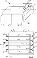
Figure 1 is a schematic perspective view of the device for adjusting the length of a neochordae, -
Figure 2 schematic top view of the device for adjusting the length of a neochordae, -
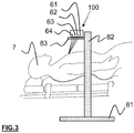
Figure 3 is a schematic view of the device offigure 1 when used on a patient. - Different examples of the device according to the invention will now be described with reference to the figures. In these different figures, equivalent elements are designated by the same numerical reference.
- As depicted in
figures 1 to 3 , thedevice 100 comprises a base 1 supporting aplate 2 slidably mounted on the base 1, and a plurality of force sensors 31-34 (two force sensors onfigure 1 , four force sensors onfigure 2 ) slidably mounted on theplate 2, each force sensor 31-34 including a gripping element 41-44 designed for handling a respective neochordae 61-64. Such a device is lightweight, compact, and easy to transport. - The base 1 can consist in a rectangular metallic platform, such as a linear table.
- The base 1 may be fixed on a support foot including a
pedestal 81, astem 82 extending vertically from thepedestal 81, and acarrier 83 fixed on an end of thestem 82 opposite to thepedestal 81, said base 1 being disposed on thecarrier 83. - This allows positioning the
device 100 near thepatient 7 to be treated, at a height sufficient to facilitate the use of thedevice 100 by the practitioner. - Advantageously, the base 1 comprises primary translational motion element on which the
plate 2 is fixed. This allows moving theplate 2 in translation relative to the base 1 in order to modify the tension of all the neochordae 61-64 handled by the plurality of gripping elements 41-44 at the same time. In particular, such a configuration enables the device to apply the same movement - and as a result the same mechanical traction - to all four neochordae 61-64. - In the embodiment illustrated on
figure 2 , the primary translational motion element comprises a primaryendless screw assembly 11 on which theplate 2 is fixed. The primaryendless screw assembly 11 is housed in a channel arranged in the base 1. The primary translational motion element further comprises aprimary setting wheel 12 fixed on one end of the primaryendless screw assembly 11 extending longitudinally outward from the base 1. - The primary
endless screw assembly 11 allows translating a rotational motion applied by the practitioner on theprimary setting wheel 12 into a linear motion of theplate 2. Preferably, the primaryendless screw assembly 11 has a linear travel of 100 millimeters and a pitch distance per revolution of 1 millimeter. This allows a precise synchronous translational displacement of the neochordae 61-64. - Alternatively, the primary translational motion element can consist in a motor embedded in the base 1, said motor being driven by the practitioner using a control panel (not shown).
- The
plate 2 can consist in a rectangular metallic platform - such as a linear table - fixed on the primary translational motion element embedded in the base 1. - Advantageously, the
plate 2 comprises a plurality of secondary translational motion elements, each secondary translational motion element supporting a respective force sensor 31-34. Each secondary translation motion element allows the displacement of its associated force sensor 31-34 with regard to theplate 2 in order to individually modify the tension of the neochordae 61-64 handled by the gripping element 41-44 fixed to the force sensor 31-34. - In the embodiment illustrated on
figure 2 , each secondary translational motion element comprises a secondary endless screw assembly 21-24 on which a respective force sensor 31-34 is fixed. Each secondary endless screw assembly 21-24 is housed in a respective channel arranged in theplate 2. Each secondary translational motion element further comprises a secondary setting wheel 25-28 fixed on one end of the secondary endless screw assembly 21-24 extending longitudinally outward from theplate 2. - Each secondary endless screw assembly 21-24 allows translating a rotational motion applied by the practitioner on the corresponding secondary setting wheel 25-28 into a linear motion of its associated force sensor 31-34. In particular, it allows to independently adjust the transverse tension exerted on each neochordae 61-64 connected to the
device 100. Preferably, each secondary endless screw assembly has a linear travel of 100 millimeters and a pitch distance per revolution of 1 millimeter. This allows a precise individual translational displacement of each neochordae 61-64. - Alternatively, each translational motion element can consist in a respective motor embedded in the
plate 2, said motors being driven individually by the practitioner using a control panel (not shown). - Each force sensor 31-34 allows measuring a signal representative of the tension of the neochordae 61-64 hold by its associated gripping element 41-44. More particularly for each neochordae 61 (respectively 62-64), its associated force sensor 31 (respectively 32-34) is adapted to measure the force exerted by the mitral valve on the neochordae 61 (respectively 62-64). This force is representative of the tension of the neochordae 61 (respectively 62-64).
- The force range of each force sensor 31-34 can be comprised between -10N and +10N. Moreover the resolution of each force sensor 31-34 may be of 0.01 N. Indeed such force range and resolution (i.e. ± 10 N and 0.01 N respectively) correspond to the constraints usually applied to the neochordae during their implantation.
- Each force sensor 31-34 can be of any type known from the skilled person. It comprises electric cables to be connected to an electric power source for powering the force sensor, and (wired or wireless) communication means for transmitting the measured signals to a processing unit (described below).
- Each gripping element 41-44 can consist in a spring clip designed to hold a respective neochordae.
- Each spring clip includes:
- two clamp elements pivotably mounted relative to each other, the clamp elements being composed of a first portion for handling the neochordae and of a second portion including tabs for pivotally moving the clamp elements relative to one another,
- a spring member bearing against each of the two clamp elements at an actuating zone thereof, to pivot the two clamp elements to a position closing the first portion.
- Advantageously, each gripping element is connected to its associated force sensor with a pivoting link for an ease of handling and comfortable neochordae locking procedure.
- Preferably, the device comprises a connecting element associated to each gripping element for releasably mounting the gripping element to its associated force sensor. This allows removing the gripping element from the force sensor in case of accidental movement of the device (for instance if a person bumps into the device during the implantation of the neochordae) in order to limit the risk of damaging the mitral valve (by pulling on the sutures fixed on the valve leaflet).
- The connecting element can comprise two permanent magnets of opposed polarity designed to cooperate, a first permanent magnet being fixed to the force sensor and a second permanent magnet being fixed to the gripping element.
- The device can further comprise a processing unit for processing (and/or displaying) the signals measured by the force sensors, and/or for controlling the moving:
- of the
plate 2 relative to the base 1, and/or - of each force sensor relative to the
plate 2. - The processing unit can be integrated to the base or may be distant from the base.
- The processing unit can consist of one (or several) work station(s) and/or one (or several) computer(s) or may be of any other type known to one skilled in the art. The control unit 6 may for example comprise a portable telephone, an electronic tablet (such as an IPAD®), a Personal Digital Assistant (or "PDA"), etc.
- In every case, the processing unit comprises a processor programmed in order to:
- control the sliding of the plate relative to the base (for instance by activating a plate motor associated to the plate), and/or
- control the sliding of each force sensor relative to the plate (for instance by activating sensor motors associated to the respective force sensors), and/or
- process the signals measured by the force sensor, and/or
- display the processed signals on a display element such as a display screen.
- With regard to the processing of the signals, the processing unit can be implemented in order to alert the practitioner when the length of the neochordae is nearly the optimal length. In particular for each force sensor, the processing unit can be adapted to detect a minimum in the forces measured by the force sensor during the translational displacement of the force sensor by the practitioner (using the secondary setting wheel).
- The operating principle of the above described device is the following.
- After the implantation - using Neochord DS 1000 - of one two three or four neochordae by capturing the free edge of the prolapsed leaflet with the capture assembly, the practitioner uses the device according to the present invention in order to adjust the length of each neochordae.
- For each neochordae, the practitioner presses the tabs of a gripping element in order to open the first portion of the clamp element. The practitioner places the neochordae into the opened first portion and stop applying a force on the tabs. The two clamp elements pivot due to the force applied by the spring member so that the first portion moves into the closed position for handling the neochordae.
- The practitioner repeats the previous steps for the different neochordae sutured to the leaflet. As shown on
figure 3 , one advantage of the device lies in the fact that it does not come into direct contact with the patient, thereby minimizing the risk of contamination. - Then the practitioner adjusts the length of the all neochordae one after the other.
- For each neochordae, the practitioner increases or decreases the length of the neochordae by rotating the
secondary setting wheel 25 associated to theneochordae 61. In particular, the rotation ofsecondary setting wheel 25 induces the translational displacement of the force sensor and gripping element handling the neochordae. - During its displacement, the force sensor continuously measures the signal representative of the tension applied to the neochordae. The processing unit displays the signal measured by the force sensor on the display means in order to facilitate the adjustment of the neochordae's length by the practitioner.
- Once the practitioner has defined the optimal length for one neochordae, he repeats the above steps for the other neochordae.
- After this step all neochordae are set in tension. An adjustment on all neochordae together can be achieved by rotating the
screw 12 under echocardiography control and thanks to the number of neochordae tension. - When a perfect correction is obtained, the neochordae are cut next to the measuring bench and a knot is archived at the right length on the external surface of the heart.
- Then the practitioner acts on the primary setting wheel in order to translate the plate with regard to the base. When the length of all neochordae have been adjusted, the practitioner fixes the other ends of the neochordae to the heart.
- The above disclosed device was tested on seven patients with severe mitral regurgitation (MR). All patients had a severe symptomatic MR due to a posterior prolapses, involving mainly P2 segment, with a variable extension on P1 or P3, but never involving the commissures or the anterior leaflet. The procedural success (defined as residual MR < Grade 2) was obtained in six patients.
- For all patients, the tension on neochordae was measured throughout the implantation procedure.
- The measurement method consists of six steps:
- i) Each chord was tested separately to decide which was the most important (generally the neochordae fixed in the middle of the prolapse);
- ii) All of the neochordae were then released;
- iii) The main neochordae was tracked alone until the best TEE control;
- iv) The other neochordae were then tracked, one at a time, with an individual screw to achieve a homogeneous tension on all neochordae;
- v) All neochordae were then tracked together using the principal screw under TEE control, until obtaining the optimal MVr with the highest coaptation of the leaflets, and the lowest tension on the neochordae; and
- vi) Measurements were then stopped, and the standard protocol was followed.
- During all steps, the neochordae tension, EKG, radial blood pressure, 3D TOE, and surgical data were continuously recorded.
- Chordae adjustment, one at a time (Step iii): While the quality of the control on the correction of the regurgitation was varying from a quasi-perfect MVr to a partial correction, the forces applied on each neochordae always had the same profile. The amplitude of forces increased progressively until a plateau value between 0.7 and 0.9 N (
Figure 3 ). This result was achieved for all patients. Interestingly, in all evaluations, we noticed a variation in the amplitude of tension of approximately 13 % following respiration (Figure 3 ). - All neochordae adjustment (Step iv): When we were setting the tension of the neochordae, one at a time, aiming to achieve the same tension in all neochordae, we observed a decrease in tension on neochordae previously set in tension. At the end of Step iv, the tension initially measured on the first neochordae was divided by the number of neochordae set in tension. Thus, when a tension of 0.8 N was observed with one neochordae, it decreased to 0.2 to 0.3 N when four neochordae are set in tension (see table below).
The mean of the sum of the amplitude of tension in all patients was 0.98 ± 0.08 N.Sequence 1 Neochordae 2 Neochordae 3 Neochordae 4 Neochordae Force amplitude Cord1 (N) 0.79 0.41 0.35 0.21 Force amplitude Cord2 (N) - 0.39 0.32 0.30 Force amplitude Cord3 (N) - - 0.30 0.22 Force amplitude Cord4 (N) - - 0.20 - Final adjustment under TEE control (Step v) : At this point of our protocol, some degree of regurgitation was usually persisting, thus requiring a final adjustment by a synchronous traction on all of the neochordae, until optimal TEE results were achieved. While the initial mean of the sum of the amplitude of tension was 0.98 ± 0.08 N before optimal correction of MR, it decreased gradually to 0.87 ± .07 N following the correction of regurgitation, corresponding to a 12 ± 2 % decrease (range: 10.3-14.1 %) during the correction. When the traction was pursued to the excessive tension, we created a tethering effect with a recurrent Type-III MR. Therefore, we had to release the tension to return to the best MR control situation.
- Compared to classical MVr, where the neochordae length adjustment on arrested hearts relies mainly on the experience of the practitioner, during novel beating heart techniques, direct, real-time evaluations are made of the quality of the MVr.
- This advance has forced practitioner to rethink the approach to MVr and represents a considerable advantage over traditional surgical techniques. With direct TEE control, it is possible to fix the length of the neochordae exactly to the optimal position; neither too long nor too short.
- The classical surgical Gore-Tex implantation mostly leads to an overcorrection, with a frozen posterior leaflet, and this likely accounts for why the ring is so important during surgical procedures. This situation might be different for percutaneous techniques, although further studies are required to determine this. Nevertheless, we expect that these types of techniques will grow in popularity as devices and the quality of the 3D images improve. Also, the correction of regurgitation using beating heart techniques represents an opportunity to explore the physiopathology of the mitral valve at every step of the procedure (e.g., clip, rings, chords).
- The transapical neochordae implantations allow direct measures of the tension applied on the neochordae of a mitral valve in a human beating heart. These data, formerly inaccessible, are innovative if we consider that data concerning the tensions exerted on the mitral valve are rare.
- To date, our knowledge about neochordae tension has relied wholly on in vitro models. Miniature C-shaped force transducers have been most widely used. In this model, the valvular tissue is harvested en masse (ring, valve, and mitral sub-valvular apparatus) from an ovine. The valve and the papillary muscle are attached to a left ventricular simulator, which can mimic the physiological hemodynamic regimen of the left ventricle. A miniature transducer is sutured in the middle of a neochordae.
- Interesting data were thus obtained, in particular concerning the differences in tension between marginal, struts, and basal neochordae. The data we obtain are consistent with those found using the miniature C-shaped force transducer model.
- Here we report data relevant to the function of the mitral subvalvular apparatus during heart beating. Our tension measurements, recorded throughout the cardiac cycle (from prolapse to tethered chordae), lead us to the following conclusions:
- a) The tension applied to a single human mitral chordae is relatively low.
Our team has already reported the various functions of primary and secondary chordae, and it is important to distinguish their specific roles. The measures presented here are only valid for primary human chordae of 0.7 to 0.8 mm, and which are attached to the free edge of the leaflets. This is probably different for secondary chordae (basal chordae or strut chordae), which are thicker (1.2 to 1.3 mm) and are not involved in neochordae implantations. Dystrophic disease does not lead to secondary chordae rupture so that they are never replaced during MVr. The stress-strain curves of a native chordae have been reported by Zuo, showing ultimate stress values around 35 MPa (equals to 35 N mm-2). In other words, a rupture of chordae should happen if a traction is applied on a normal chordae of 1 mm2 and of a prolapsed area if the tension is 35-times superior to the physiologic traction. This likely never happens, meaning that the ruptures of the chordae we encountered among our patients are likely a consequence of the fragility of the diseased chordae, rather than to excessive forces. Gore-Tex® sutures (CV-4 or CV-5) are typically used as neochordae. The diameter of these sutures vary from 0.15 to 0.25 mm and their strength is perfectly adapted since the rupture point is at around 35 N, giving a comfortable safety margin. Moreover, we noticed that the forces applied to the subvalvular apparatus vary with respiration. This might account for why some exceptional thoracic traumatism with the sudden increase of the intra-thoracic pressure can lead to traumatic rupture of normal chordae and acute MR. - b) The tension is divided by the number of chordae set in tension.
Tension decreased as the number of chordae set in tension increased. This finding, although intuitively expected, is physically confirmed here, with an almost strictly mathematical correlation. The spider's web-structure of the subvalvular apparatus, with numerous chordae and numerous implantation sites on the leaflets, is essential. Intuitively, we could presume that it is also necessary to use several chordae to fix a large prolapse, all along its free edge. Also, an increased number of chordae would likely make the repair less fragile and more durable. - c) The global tension decreases when the control of the regurgitation is optimal
The normal valve seems to work in a low-stress regimen. In other words, in a physiological state, the perfect systolic closure of the mitral valve with two coapted leaflets inside a 3D saddle shape annular plan corresponds to the situation with the lowest tension on the subvalvular apparatus. Few physiological explanations can be suggested to explain this finding:- As mention above, the total tension is divided by the number of chordae. After MR correction, the global tension is distributed between native and artificial chordae. Thus, the tension applied on neochordae (the only one that we can measure) is decreased.
- The above disclosed device allows adjusting the length of neochordae during beating-heart-MVr according to a strict control of their tensions.
- In addition, the above described device has allowed the inventor to report original, clinically useful data concerning the physiopathology of the sub-valvular apparatus. Their principal findings are that:
- the tension applied on one human mitral chordae is low;
- the tension is divided by the number of neochordae set in tension; and
- the lowest tension on all neochordae is observed when the control of the regurgitation is optimal.
- The skilled person will have understood that many modifications may be provided to the invention described earlier without materially departing from the new teachings and advantages described here. Therefore, all the modifications of this type are intended to be incorporated inside the scope of the appended claims.
Claims (15)
- Device (100) for assisting a practitioner in adjusting the length of artificial chordae (61-64) implanted in an heart valve, the device (100) comprising a plurality of gripping elements (41-44), each gripping element (41-44) handling an end of a respective artificial chordae (61-64) extending outward from the patient (7) so that the device (100) remains outside from the patient (7),
characterized in that
the device (100) further comprises a plurality of force sensors (31-34), each force sensor being fixed to a respective gripping element (41-44) for measuring a signal representative of a tension of the chordae (61-64) hold by the gripping element (41-44) associated to the force sensor. - Device according to claim 1, further comprising a plate (2) including a plurality of secondary translational motion elements, each secondary translational motion element supporting a respective force sensor (31-34) so that each force sensor (31-34) is slidably mounted on the plate (2).
- Device according to claim 2, wherein each secondary translational motion element allows individually moving a respective force sensor (31-34) in translation, each secondary translational motion element including:- a secondary endless screw assembly (21-24) on which a respective force sensor (31-34) is fixed,- a secondary setting wheel (25-28) fixed on one end of the secondary endless screw assembly (21-24) extending longitudinally outward from the plate (2).
- Device according to claim 3, wherein each secondary endless screw assembly (21-24) has a linear travel of 100 millimeters and a pitch distance per revolution of 1 millimeter.
- Device according to anyone of claims 1 to 4, further comprising a base (1) including a primary translational motion element connected to the plurality of force sensors (31-34) so that each force sensor (31-34) is slidably mounted on the base (1).
- Device according to claim 5, wherein the primary translational motion element allows synchronously moving the plurality of force sensors (31-34) in translation, the primary translational motion element including:- a primary endless screw assembly (11) connected to the plurality of force sensors (31-34),- a primary setting wheel (12) fixed on one end of the primary endless screw assembly (11) extending longitudinally outward from the base (1).
- Device according to claim 6, wherein the primary endless screw assembly (11) has a linear travel of 100 millimeters and a pitch distance per revolution of 1 millimeter
- Device according to claims 2 and 5 taken in combination, wherein the plate (2) is fixed on the primary translational motion element so that the plate (2) is slidably mounted on the base (1).
- Device according to anyone of claims 1 to 8, wherein each gripping element (41-44) consists in a spring clip designed to hold a respective chordae (61-64).
- Device according to anyone of claims 1 to 9, further comprising a plurality of connecting elements, each connecting element extending between a force sensor (31-34) and a respective gripping element (41-44) in order to releasably fix the force sensor (31-34) to the respective gripping element (41-44).
- Device according to claim 9, wherein each connecting element comprises two permanent magnets of opposed polarity designed to cooperate, a first permanent magnet being fixed to the force sensor (31-34) and a second permanent magnet being fixed to the gripping element (41-44) associated to the force sensor (31-34).
- Device according to anyone of claims 1 to 11, further comprising a processing unit for processing and/or displaying the signals measured by the force sensors (31-34).
- Device according to claim 12, wherein for each force sensor (31-34), the processing unit is adapted to detect a minimum in the forces measured by the force sensor (31-34) during its translational displacement with regard to the plate (2).
- Device according to claim 13, wherein the processing unit is adapted to alert the practitioner when the length of the chordae is near from an optimal length.
- Device according to claim 14, wherein the processing unit is adapted to emit a visual or auditory stimulus when the length of the chordae is near from an optimal length.
Priority Applications (2)
| Application Number | Priority Date | Filing Date | Title |
|---|---|---|---|
| EP18157633.1A EP3527170B1 (en) | 2018-02-20 | 2018-02-20 | Device for assisting a practitioner in adjusting the length of an artificial chordae implanted in an atrio-ventricular heart valve |
| PCT/EP2019/054023 WO2019162244A1 (en) | 2018-02-20 | 2019-02-19 | Device for assisting a practitioner in adjusting the length of several articificial chordae implanted in an atrio-ventricular heart valve |
Applications Claiming Priority (1)
| Application Number | Priority Date | Filing Date | Title |
|---|---|---|---|
| EP18157633.1A EP3527170B1 (en) | 2018-02-20 | 2018-02-20 | Device for assisting a practitioner in adjusting the length of an artificial chordae implanted in an atrio-ventricular heart valve |
Publications (2)
| Publication Number | Publication Date |
|---|---|
| EP3527170A1 true EP3527170A1 (en) | 2019-08-21 |
| EP3527170B1 EP3527170B1 (en) | 2020-11-18 |
Family
ID=61249578
Family Applications (1)
| Application Number | Title | Priority Date | Filing Date |
|---|---|---|---|
| EP18157633.1A Not-in-force EP3527170B1 (en) | 2018-02-20 | 2018-02-20 | Device for assisting a practitioner in adjusting the length of an artificial chordae implanted in an atrio-ventricular heart valve |
Country Status (2)
| Country | Link |
|---|---|
| EP (1) | EP3527170B1 (en) |
| WO (1) | WO2019162244A1 (en) |
Cited By (15)
| Publication number | Priority date | Publication date | Assignee | Title |
|---|---|---|---|---|
| US10940001B2 (en) | 2012-05-30 | 2021-03-09 | Neovasc Tiara Inc. | Methods and apparatus for loading a prosthesis onto a delivery system |
| US11311376B2 (en) | 2019-06-20 | 2022-04-26 | Neovase Tiara Inc. | Low profile prosthetic mitral valve |
| US11357622B2 (en) | 2016-01-29 | 2022-06-14 | Neovase Tiara Inc. | Prosthetic valve for avoiding obstruction of outflow |
| US11389291B2 (en) | 2013-04-04 | 2022-07-19 | Neovase Tiara Inc. | Methods and apparatus for delivering a prosthetic valve to a beating heart |
| US11413139B2 (en) | 2011-11-23 | 2022-08-16 | Neovasc Tiara Inc. | Sequentially deployed transcatheter mitral valve prosthesis |
| US11419720B2 (en) | 2010-05-05 | 2022-08-23 | Neovasc Tiara Inc. | Transcatheter mitral valve prosthesis |
| US11464631B2 (en) | 2016-11-21 | 2022-10-11 | Neovasc Tiara Inc. | Methods and systems for rapid retraction of a transcatheter heart valve delivery system |
| US11491006B2 (en) | 2019-04-10 | 2022-11-08 | Neovasc Tiara Inc. | Prosthetic valve with natural blood flow |
| US11497602B2 (en) | 2012-02-14 | 2022-11-15 | Neovasc Tiara Inc. | Methods and apparatus for engaging a valve prosthesis with tissue |
| US11602429B2 (en) | 2019-04-01 | 2023-03-14 | Neovasc Tiara Inc. | Controllably deployable prosthetic valve |
| US11737872B2 (en) | 2018-11-08 | 2023-08-29 | Neovasc Tiara Inc. | Ventricular deployment of a transcatheter mitral valve prosthesis |
| US11779742B2 (en) | 2019-05-20 | 2023-10-10 | Neovasc Tiara Inc. | Introducer with hemostasis mechanism |
| US11793640B2 (en) | 2017-08-25 | 2023-10-24 | Neovasc Tiara Inc. | Sequentially deployed transcatheter mitral valve prosthesis |
| US11998447B2 (en) | 2019-03-08 | 2024-06-04 | Neovasc Tiara Inc. | Retrievable prosthesis delivery system |
| US12109111B2 (en) | 2015-12-15 | 2024-10-08 | Neovasc Tiara Inc. | Transseptal delivery system |
Families Citing this family (2)
| Publication number | Priority date | Publication date | Assignee | Title |
|---|---|---|---|---|
| CN113520670B (en) * | 2020-04-15 | 2024-12-20 | 杭州德晋医疗科技有限公司 | Rotating artificial chord adjustment system |
| CN119023238B (en) * | 2024-10-28 | 2025-04-04 | 上海市医疗器械检验研究院 | Multifunctional mitral regurgitation simulation device and construction method |
Citations (2)
| Publication number | Priority date | Publication date | Assignee | Title |
|---|---|---|---|---|
| US20110288635A1 (en) * | 2010-05-24 | 2011-11-24 | Valtech Cardio, Ltd. | Adjustable artificial chordeae tendineae with suture loops |
| WO2015138306A2 (en) * | 2014-03-10 | 2015-09-17 | Tendyne Holdings, Inc. | Devices and methods for positioning and monitoring tether load for prosthetic mitral valve |
Family Cites Families (2)
| Publication number | Priority date | Publication date | Assignee | Title |
|---|---|---|---|---|
| US6679889B1 (en) * | 2000-11-13 | 2004-01-20 | Hs West Investments, Llc | Apparatus and methods for independently conditioning and pretensioning a plurality of ligament grafts during joint repair surgery |
| US8845723B2 (en) * | 2007-03-13 | 2014-09-30 | Mitralign, Inc. | Systems and methods for introducing elements into tissue |
-
2018
- 2018-02-20 EP EP18157633.1A patent/EP3527170B1/en not_active Not-in-force
-
2019
- 2019-02-19 WO PCT/EP2019/054023 patent/WO2019162244A1/en not_active Ceased
Patent Citations (2)
| Publication number | Priority date | Publication date | Assignee | Title |
|---|---|---|---|---|
| US20110288635A1 (en) * | 2010-05-24 | 2011-11-24 | Valtech Cardio, Ltd. | Adjustable artificial chordeae tendineae with suture loops |
| WO2015138306A2 (en) * | 2014-03-10 | 2015-09-17 | Tendyne Holdings, Inc. | Devices and methods for positioning and monitoring tether load for prosthetic mitral valve |
Cited By (24)
| Publication number | Priority date | Publication date | Assignee | Title |
|---|---|---|---|---|
| US11419720B2 (en) | 2010-05-05 | 2022-08-23 | Neovasc Tiara Inc. | Transcatheter mitral valve prosthesis |
| US12611303B2 (en) | 2010-05-05 | 2026-04-28 | Neovasc Tiara Inc. | Transcatheter mitral valve prosthesis |
| US12053369B2 (en) | 2011-11-23 | 2024-08-06 | Neovasc Tiara Inc. | Sequentially deployed transcatheter mitral valve prosthesis |
| US11413139B2 (en) | 2011-11-23 | 2022-08-16 | Neovasc Tiara Inc. | Sequentially deployed transcatheter mitral valve prosthesis |
| US11497602B2 (en) | 2012-02-14 | 2022-11-15 | Neovasc Tiara Inc. | Methods and apparatus for engaging a valve prosthesis with tissue |
| US12138159B2 (en) | 2012-02-14 | 2024-11-12 | Neovasc Tiara Inc. | Methods and apparatus for engaging a valve prosthesis with tissue |
| US11617650B2 (en) | 2012-05-30 | 2023-04-04 | Neovasc Tiara Inc. | Methods and apparatus for loading a prosthesis onto a delivery system |
| US10940001B2 (en) | 2012-05-30 | 2021-03-09 | Neovasc Tiara Inc. | Methods and apparatus for loading a prosthesis onto a delivery system |
| US11389294B2 (en) | 2012-05-30 | 2022-07-19 | Neovasc Tiara Inc. | Methods and apparatus for loading a prosthesis onto a delivery system |
| US11389291B2 (en) | 2013-04-04 | 2022-07-19 | Neovase Tiara Inc. | Methods and apparatus for delivering a prosthetic valve to a beating heart |
| US12109111B2 (en) | 2015-12-15 | 2024-10-08 | Neovasc Tiara Inc. | Transseptal delivery system |
| US11357622B2 (en) | 2016-01-29 | 2022-06-14 | Neovase Tiara Inc. | Prosthetic valve for avoiding obstruction of outflow |
| US12193932B2 (en) | 2016-01-29 | 2025-01-14 | Neovasc Tiara Inc. | Prosthetic valve for avoiding obstruction of outflow |
| US11464631B2 (en) | 2016-11-21 | 2022-10-11 | Neovasc Tiara Inc. | Methods and systems for rapid retraction of a transcatheter heart valve delivery system |
| US12201524B2 (en) | 2016-11-21 | 2025-01-21 | Neovasc Tiara Inc. | Methods and systems for rapid retraction of a transcatheter heart valve delivery system |
| US11793640B2 (en) | 2017-08-25 | 2023-10-24 | Neovasc Tiara Inc. | Sequentially deployed transcatheter mitral valve prosthesis |
| US11737872B2 (en) | 2018-11-08 | 2023-08-29 | Neovasc Tiara Inc. | Ventricular deployment of a transcatheter mitral valve prosthesis |
| US11998447B2 (en) | 2019-03-08 | 2024-06-04 | Neovasc Tiara Inc. | Retrievable prosthesis delivery system |
| US11602429B2 (en) | 2019-04-01 | 2023-03-14 | Neovasc Tiara Inc. | Controllably deployable prosthetic valve |
| US11491006B2 (en) | 2019-04-10 | 2022-11-08 | Neovasc Tiara Inc. | Prosthetic valve with natural blood flow |
| US12036117B2 (en) | 2019-04-10 | 2024-07-16 | Neovasc Tiara Inc. | Prosthetic valve with natural blood flow |
| US11779742B2 (en) | 2019-05-20 | 2023-10-10 | Neovasc Tiara Inc. | Introducer with hemostasis mechanism |
| US11931254B2 (en) | 2019-06-20 | 2024-03-19 | Neovasc Tiara Inc. | Low profile prosthetic mitral valve |
| US11311376B2 (en) | 2019-06-20 | 2022-04-26 | Neovase Tiara Inc. | Low profile prosthetic mitral valve |
Also Published As
| Publication number | Publication date |
|---|---|
| WO2019162244A1 (en) | 2019-08-29 |
| EP3527170B1 (en) | 2020-11-18 |
Similar Documents
| Publication | Publication Date | Title |
|---|---|---|
| EP3527170B1 (en) | Device for assisting a practitioner in adjusting the length of an artificial chordae implanted in an atrio-ventricular heart valve | |
| US8206439B2 (en) | Internal prosthesis for reconstruction of cardiac geometry | |
| CN112773566B (en) | A universal heart valve disease interventional device stabilizer | |
| Jensen et al. | Saddle-shaped mitral valve annuloplasty rings improve leaflet coaptation geometry | |
| US11369472B2 (en) | Heart valve implant and heart valve implant system | |
| Grossi et al. | Intraoperative effects of the Coapsys annuloplasty system in a randomized evaluation (RESTOR-MV) of functional ischemic mitral regurgitation | |
| CN1897893A (en) | Prosthetic valve devices, especially for the heart | |
| CN104665888A (en) | Mitral chordae sewing machine for implanting artificial chordae through minimally invasive technology and method of mitral chordae sewing machine | |
| CN103987341B (en) | Apparatus and method for treating a regurgitant heart valve | |
| Jensen et al. | Transapical neochord implantation: is tension of artificial chordae tendineae dependent on the insertion site? | |
| CN112932743B (en) | Prosthesis system with positioning mechanism | |
| CN118303959A (en) | Auxiliary positioning device for surgical puncture | |
| Ropcke et al. | Functional and biomechanical performance of stentless extracellular matrix tricuspid tube graft: an acute experimental porcine evaluation | |
| WO2012020415A2 (en) | Annuloplasty prostheses and surgical techniques | |
| Saxon et al. | Bioprosthetic valve remodeling of trifecta surgical valves to facilitate valve-in-valve TAVR | |
| Rankin et al. | Technique for aortic valve annuloplasty using an intra-annular “hemispherical” frame | |
| CN216455492U (en) | A universal heart valve disease intervention device stabilizer | |
| US8133168B2 (en) | Remediation of functional cardiac mitral valve regurgitation | |
| Easley et al. | Effects of annular contraction on anterior leaflet strain using an in vitro simulator with a dynamically contracting mitral annulus | |
| CN214967154U (en) | Prosthesis system with positioning mechanism | |
| CN117598838B (en) | Heart valve forming system | |
| CN116725736A (en) | Implantation instrument for repairing valve | |
| CN206463091U (en) | A kind of artificial mitral valve forming ring | |
| RU204725U1 (en) | Template for tricuspid valve repair | |
| Gogbashian et al. | Correction of aortic insufficiency with an external adjustable prosthetic aortic ring |
Legal Events
| Date | Code | Title | Description |
|---|---|---|---|
| PUAI | Public reference made under article 153(3) epc to a published international application that has entered the european phase |
Free format text: ORIGINAL CODE: 0009012 |
|
| STAA | Information on the status of an ep patent application or granted ep patent |
Free format text: STATUS: THE APPLICATION HAS BEEN PUBLISHED |
|
| AK | Designated contracting states |
Kind code of ref document: A1 Designated state(s): AL AT BE BG CH CY CZ DE DK EE ES FI FR GB GR HR HU IE IS IT LI LT LU LV MC MK MT NL NO PL PT RO RS SE SI SK SM TR |
|
| AX | Request for extension of the european patent |
Extension state: BA ME |
|
| STAA | Information on the status of an ep patent application or granted ep patent |
Free format text: STATUS: REQUEST FOR EXAMINATION WAS MADE |
|
| 17P | Request for examination filed |
Effective date: 20191023 |
|
| RBV | Designated contracting states (corrected) |
Designated state(s): AL AT BE BG CH CY CZ DE DK EE ES FI FR GB GR HR HU IE IS IT LI LT LU LV MC MK MT NL NO PL PT RO RS SE SI SK SM TR |
|
| GRAP | Despatch of communication of intention to grant a patent |
Free format text: ORIGINAL CODE: EPIDOSNIGR1 |
|
| STAA | Information on the status of an ep patent application or granted ep patent |
Free format text: STATUS: GRANT OF PATENT IS INTENDED |
|
| INTG | Intention to grant announced |
Effective date: 20200603 |
|
| GRAS | Grant fee paid |
Free format text: ORIGINAL CODE: EPIDOSNIGR3 |
|
| GRAA | (expected) grant |
Free format text: ORIGINAL CODE: 0009210 |
|
| STAA | Information on the status of an ep patent application or granted ep patent |
Free format text: STATUS: THE PATENT HAS BEEN GRANTED |
|
| AK | Designated contracting states |
Kind code of ref document: B1 Designated state(s): AL AT BE BG CH CY CZ DE DK EE ES FI FR GB GR HR HU IE IS IT LI LT LU LV MC MK MT NL NO PL PT RO RS SE SI SK SM TR |
|
| REG | Reference to a national code |
Ref country code: GB Ref legal event code: FG4D |
|
| REG | Reference to a national code |
Ref country code: CH Ref legal event code: EP |
|
| REG | Reference to a national code |
Ref country code: IE Ref legal event code: FG4D |
|
| REG | Reference to a national code |
Ref country code: DE Ref legal event code: R096 Ref document number: 602018009712 Country of ref document: DE |
|
| REG | Reference to a national code |
Ref country code: AT Ref legal event code: REF Ref document number: 1334911 Country of ref document: AT Kind code of ref document: T Effective date: 20201215 |
|
| REG | Reference to a national code |
Ref country code: AT Ref legal event code: MK05 Ref document number: 1334911 Country of ref document: AT Kind code of ref document: T Effective date: 20201118 |
|
| REG | Reference to a national code |
Ref country code: NL Ref legal event code: MP Effective date: 20201118 |
|
| PG25 | Lapsed in a contracting state [announced via postgrant information from national office to epo] |
Ref country code: PT Free format text: LAPSE BECAUSE OF FAILURE TO SUBMIT A TRANSLATION OF THE DESCRIPTION OR TO PAY THE FEE WITHIN THE PRESCRIBED TIME-LIMIT Effective date: 20210318 Ref country code: RS Free format text: LAPSE BECAUSE OF FAILURE TO SUBMIT A TRANSLATION OF THE DESCRIPTION OR TO PAY THE FEE WITHIN THE PRESCRIBED TIME-LIMIT Effective date: 20201118 Ref country code: FI Free format text: LAPSE BECAUSE OF FAILURE TO SUBMIT A TRANSLATION OF THE DESCRIPTION OR TO PAY THE FEE WITHIN THE PRESCRIBED TIME-LIMIT Effective date: 20201118 Ref country code: NO Free format text: LAPSE BECAUSE OF FAILURE TO SUBMIT A TRANSLATION OF THE DESCRIPTION OR TO PAY THE FEE WITHIN THE PRESCRIBED TIME-LIMIT Effective date: 20210218 Ref country code: GR Free format text: LAPSE BECAUSE OF FAILURE TO SUBMIT A TRANSLATION OF THE DESCRIPTION OR TO PAY THE FEE WITHIN THE PRESCRIBED TIME-LIMIT Effective date: 20210219 |
|
| PG25 | Lapsed in a contracting state [announced via postgrant information from national office to epo] |
Ref country code: AT Free format text: LAPSE BECAUSE OF FAILURE TO SUBMIT A TRANSLATION OF THE DESCRIPTION OR TO PAY THE FEE WITHIN THE PRESCRIBED TIME-LIMIT Effective date: 20201118 Ref country code: BG Free format text: LAPSE BECAUSE OF FAILURE TO SUBMIT A TRANSLATION OF THE DESCRIPTION OR TO PAY THE FEE WITHIN THE PRESCRIBED TIME-LIMIT Effective date: 20210218 Ref country code: PL Free format text: LAPSE BECAUSE OF FAILURE TO SUBMIT A TRANSLATION OF THE DESCRIPTION OR TO PAY THE FEE WITHIN THE PRESCRIBED TIME-LIMIT Effective date: 20201118 Ref country code: LV Free format text: LAPSE BECAUSE OF FAILURE TO SUBMIT A TRANSLATION OF THE DESCRIPTION OR TO PAY THE FEE WITHIN THE PRESCRIBED TIME-LIMIT Effective date: 20201118 Ref country code: IS Free format text: LAPSE BECAUSE OF FAILURE TO SUBMIT A TRANSLATION OF THE DESCRIPTION OR TO PAY THE FEE WITHIN THE PRESCRIBED TIME-LIMIT Effective date: 20210318 Ref country code: SE Free format text: LAPSE BECAUSE OF FAILURE TO SUBMIT A TRANSLATION OF THE DESCRIPTION OR TO PAY THE FEE WITHIN THE PRESCRIBED TIME-LIMIT Effective date: 20201118 |
|
| REG | Reference to a national code |
Ref country code: LT Ref legal event code: MG9D |
|
| PG25 | Lapsed in a contracting state [announced via postgrant information from national office to epo] |
Ref country code: HR Free format text: LAPSE BECAUSE OF FAILURE TO SUBMIT A TRANSLATION OF THE DESCRIPTION OR TO PAY THE FEE WITHIN THE PRESCRIBED TIME-LIMIT Effective date: 20201118 |
|
| PG25 | Lapsed in a contracting state [announced via postgrant information from national office to epo] |
Ref country code: SK Free format text: LAPSE BECAUSE OF FAILURE TO SUBMIT A TRANSLATION OF THE DESCRIPTION OR TO PAY THE FEE WITHIN THE PRESCRIBED TIME-LIMIT Effective date: 20201118 Ref country code: RO Free format text: LAPSE BECAUSE OF FAILURE TO SUBMIT A TRANSLATION OF THE DESCRIPTION OR TO PAY THE FEE WITHIN THE PRESCRIBED TIME-LIMIT Effective date: 20201118 Ref country code: SM Free format text: LAPSE BECAUSE OF FAILURE TO SUBMIT A TRANSLATION OF THE DESCRIPTION OR TO PAY THE FEE WITHIN THE PRESCRIBED TIME-LIMIT Effective date: 20201118 Ref country code: CZ Free format text: LAPSE BECAUSE OF FAILURE TO SUBMIT A TRANSLATION OF THE DESCRIPTION OR TO PAY THE FEE WITHIN THE PRESCRIBED TIME-LIMIT Effective date: 20201118 Ref country code: EE Free format text: LAPSE BECAUSE OF FAILURE TO SUBMIT A TRANSLATION OF THE DESCRIPTION OR TO PAY THE FEE WITHIN THE PRESCRIBED TIME-LIMIT Effective date: 20201118 Ref country code: LT Free format text: LAPSE BECAUSE OF FAILURE TO SUBMIT A TRANSLATION OF THE DESCRIPTION OR TO PAY THE FEE WITHIN THE PRESCRIBED TIME-LIMIT Effective date: 20201118 |
|
| REG | Reference to a national code |
Ref country code: DE Ref legal event code: R097 Ref document number: 602018009712 Country of ref document: DE |
|
| PG25 | Lapsed in a contracting state [announced via postgrant information from national office to epo] |
Ref country code: DK Free format text: LAPSE BECAUSE OF FAILURE TO SUBMIT A TRANSLATION OF THE DESCRIPTION OR TO PAY THE FEE WITHIN THE PRESCRIBED TIME-LIMIT Effective date: 20201118 |
|
| PLBE | No opposition filed within time limit |
Free format text: ORIGINAL CODE: 0009261 |
|
| STAA | Information on the status of an ep patent application or granted ep patent |
Free format text: STATUS: NO OPPOSITION FILED WITHIN TIME LIMIT |
|
| PG25 | Lapsed in a contracting state [announced via postgrant information from national office to epo] |
Ref country code: MC Free format text: LAPSE BECAUSE OF FAILURE TO SUBMIT A TRANSLATION OF THE DESCRIPTION OR TO PAY THE FEE WITHIN THE PRESCRIBED TIME-LIMIT Effective date: 20201118 |
|
| 26N | No opposition filed |
Effective date: 20210819 |
|
| REG | Reference to a national code |
Ref country code: BE Ref legal event code: MM Effective date: 20210228 |
|
| PG25 | Lapsed in a contracting state [announced via postgrant information from national office to epo] |
Ref country code: NL Free format text: LAPSE BECAUSE OF FAILURE TO SUBMIT A TRANSLATION OF THE DESCRIPTION OR TO PAY THE FEE WITHIN THE PRESCRIBED TIME-LIMIT Effective date: 20201118 Ref country code: AL Free format text: LAPSE BECAUSE OF FAILURE TO SUBMIT A TRANSLATION OF THE DESCRIPTION OR TO PAY THE FEE WITHIN THE PRESCRIBED TIME-LIMIT Effective date: 20201118 Ref country code: CH Free format text: LAPSE BECAUSE OF NON-PAYMENT OF DUE FEES Effective date: 20210228 Ref country code: IT Free format text: LAPSE BECAUSE OF FAILURE TO SUBMIT A TRANSLATION OF THE DESCRIPTION OR TO PAY THE FEE WITHIN THE PRESCRIBED TIME-LIMIT Effective date: 20201118 Ref country code: LI Free format text: LAPSE BECAUSE OF NON-PAYMENT OF DUE FEES Effective date: 20210228 Ref country code: LU Free format text: LAPSE BECAUSE OF NON-PAYMENT OF DUE FEES Effective date: 20210220 |
|
| PG25 | Lapsed in a contracting state [announced via postgrant information from national office to epo] |
Ref country code: SI Free format text: LAPSE BECAUSE OF FAILURE TO SUBMIT A TRANSLATION OF THE DESCRIPTION OR TO PAY THE FEE WITHIN THE PRESCRIBED TIME-LIMIT Effective date: 20201118 |
|
| PG25 | Lapsed in a contracting state [announced via postgrant information from national office to epo] |
Ref country code: ES Free format text: LAPSE BECAUSE OF FAILURE TO SUBMIT A TRANSLATION OF THE DESCRIPTION OR TO PAY THE FEE WITHIN THE PRESCRIBED TIME-LIMIT Effective date: 20201118 Ref country code: IE Free format text: LAPSE BECAUSE OF NON-PAYMENT OF DUE FEES Effective date: 20210220 |
|
| PG25 | Lapsed in a contracting state [announced via postgrant information from national office to epo] |
Ref country code: IS Free format text: LAPSE BECAUSE OF FAILURE TO SUBMIT A TRANSLATION OF THE DESCRIPTION OR TO PAY THE FEE WITHIN THE PRESCRIBED TIME-LIMIT Effective date: 20210318 |
|
| PG25 | Lapsed in a contracting state [announced via postgrant information from national office to epo] |
Ref country code: BE Free format text: LAPSE BECAUSE OF NON-PAYMENT OF DUE FEES Effective date: 20210228 |
|
| PGFP | Annual fee paid to national office [announced via postgrant information from national office to epo] |
Ref country code: FR Payment date: 20230228 Year of fee payment: 6 |
|
| PGFP | Annual fee paid to national office [announced via postgrant information from national office to epo] |
Ref country code: GB Payment date: 20230222 Year of fee payment: 6 Ref country code: DE Payment date: 20230207 Year of fee payment: 6 |
|
| PG25 | Lapsed in a contracting state [announced via postgrant information from national office to epo] |
Ref country code: CY Free format text: LAPSE BECAUSE OF FAILURE TO SUBMIT A TRANSLATION OF THE DESCRIPTION OR TO PAY THE FEE WITHIN THE PRESCRIBED TIME-LIMIT Effective date: 20201118 |
|
| PG25 | Lapsed in a contracting state [announced via postgrant information from national office to epo] |
Ref country code: HU Free format text: LAPSE BECAUSE OF FAILURE TO SUBMIT A TRANSLATION OF THE DESCRIPTION OR TO PAY THE FEE WITHIN THE PRESCRIBED TIME-LIMIT; INVALID AB INITIO Effective date: 20180220 |
|
| PG25 | Lapsed in a contracting state [announced via postgrant information from national office to epo] |
Ref country code: MK Free format text: LAPSE BECAUSE OF FAILURE TO SUBMIT A TRANSLATION OF THE DESCRIPTION OR TO PAY THE FEE WITHIN THE PRESCRIBED TIME-LIMIT Effective date: 20201118 |
|
| PG25 | Lapsed in a contracting state [announced via postgrant information from national office to epo] |
Ref country code: TR Free format text: LAPSE BECAUSE OF FAILURE TO SUBMIT A TRANSLATION OF THE DESCRIPTION OR TO PAY THE FEE WITHIN THE PRESCRIBED TIME-LIMIT Effective date: 20201118 |
|
| REG | Reference to a national code |
Ref country code: DE Ref legal event code: R119 Ref document number: 602018009712 Country of ref document: DE |
|
| PG25 | Lapsed in a contracting state [announced via postgrant information from national office to epo] |
Ref country code: MT Free format text: LAPSE BECAUSE OF FAILURE TO SUBMIT A TRANSLATION OF THE DESCRIPTION OR TO PAY THE FEE WITHIN THE PRESCRIBED TIME-LIMIT Effective date: 20201118 |
|
| GBPC | Gb: european patent ceased through non-payment of renewal fee |
Effective date: 20240220 |
|
| PG25 | Lapsed in a contracting state [announced via postgrant information from national office to epo] |
Ref country code: DE Free format text: LAPSE BECAUSE OF NON-PAYMENT OF DUE FEES Effective date: 20240903 |
|
| PG25 | Lapsed in a contracting state [announced via postgrant information from national office to epo] |
Ref country code: GB Free format text: LAPSE BECAUSE OF NON-PAYMENT OF DUE FEES Effective date: 20240220 |
|
| PG25 | Lapsed in a contracting state [announced via postgrant information from national office to epo] |
Ref country code: FR Free format text: LAPSE BECAUSE OF NON-PAYMENT OF DUE FEES Effective date: 20240229 |
|
| PG25 | Lapsed in a contracting state [announced via postgrant information from national office to epo] |
Ref country code: GB Free format text: LAPSE BECAUSE OF NON-PAYMENT OF DUE FEES Effective date: 20240220 Ref country code: FR Free format text: LAPSE BECAUSE OF NON-PAYMENT OF DUE FEES Effective date: 20240229 Ref country code: DE Free format text: LAPSE BECAUSE OF NON-PAYMENT OF DUE FEES Effective date: 20240903 |