EP3526511B1 - Multi-layer protective window system for non-military heavy equipment and method for fabricating same - Google Patents
Multi-layer protective window system for non-military heavy equipment and method for fabricating same Download PDFInfo
- Publication number
- EP3526511B1 EP3526511B1 EP17859848.8A EP17859848A EP3526511B1 EP 3526511 B1 EP3526511 B1 EP 3526511B1 EP 17859848 A EP17859848 A EP 17859848A EP 3526511 B1 EP3526511 B1 EP 3526511B1
- Authority
- EP
- European Patent Office
- Prior art keywords
- window
- panes
- air gap
- pane
- window system
- Prior art date
- Legal status (The legal status is an assumption and is not a legal conclusion. Google has not performed a legal analysis and makes no representation as to the accuracy of the status listed.)
- Active
Links
Images



Classifications
-
- B—PERFORMING OPERATIONS; TRANSPORTING
- B60—VEHICLES IN GENERAL
- B60J—WINDOWS, WINDSCREENS, NON-FIXED ROOFS, DOORS, OR SIMILAR DEVICES FOR VEHICLES; REMOVABLE EXTERNAL PROTECTIVE COVERINGS SPECIALLY ADAPTED FOR VEHICLES
- B60J1/00—Windows; Windscreens; Accessories therefor
- B60J1/001—Double glazing for vehicles
-
- B—PERFORMING OPERATIONS; TRANSPORTING
- B60—VEHICLES IN GENERAL
- B60J—WINDOWS, WINDSCREENS, NON-FIXED ROOFS, DOORS, OR SIMILAR DEVICES FOR VEHICLES; REMOVABLE EXTERNAL PROTECTIVE COVERINGS SPECIALLY ADAPTED FOR VEHICLES
- B60J1/00—Windows; Windscreens; Accessories therefor
- B60J1/002—Windows; Windscreens; Accessories therefor with means for clear vision, e.g. anti-frost or defog panes, rain shields
-
- B—PERFORMING OPERATIONS; TRANSPORTING
- B60—VEHICLES IN GENERAL
- B60J—WINDOWS, WINDSCREENS, NON-FIXED ROOFS, DOORS, OR SIMILAR DEVICES FOR VEHICLES; REMOVABLE EXTERNAL PROTECTIVE COVERINGS SPECIALLY ADAPTED FOR VEHICLES
- B60J1/00—Windows; Windscreens; Accessories therefor
- B60J1/02—Windows; Windscreens; Accessories therefor arranged at the vehicle front, e.g. structure of the glazing, mounting of the glazing
-
- B—PERFORMING OPERATIONS; TRANSPORTING
- B60—VEHICLES IN GENERAL
- B60J—WINDOWS, WINDSCREENS, NON-FIXED ROOFS, DOORS, OR SIMILAR DEVICES FOR VEHICLES; REMOVABLE EXTERNAL PROTECTIVE COVERINGS SPECIALLY ADAPTED FOR VEHICLES
- B60J1/00—Windows; Windscreens; Accessories therefor
- B60J1/02—Windows; Windscreens; Accessories therefor arranged at the vehicle front, e.g. structure of the glazing, mounting of the glazing
- B60J1/04—Windows; Windscreens; Accessories therefor arranged at the vehicle front, e.g. structure of the glazing, mounting of the glazing adjustable
- B60J1/06—Windows; Windscreens; Accessories therefor arranged at the vehicle front, e.g. structure of the glazing, mounting of the glazing adjustable comprising more than one pane
-
- B—PERFORMING OPERATIONS; TRANSPORTING
- B60—VEHICLES IN GENERAL
- B60J—WINDOWS, WINDSCREENS, NON-FIXED ROOFS, DOORS, OR SIMILAR DEVICES FOR VEHICLES; REMOVABLE EXTERNAL PROTECTIVE COVERINGS SPECIALLY ADAPTED FOR VEHICLES
- B60J1/00—Windows; Windscreens; Accessories therefor
- B60J1/20—Accessories, e.g. wind deflectors, blinds
- B60J1/2094—Protective means for window, e.g. additional panel or foil, against vandalism, dirt, wear, shattered glass, etc.
-
- E—FIXED CONSTRUCTIONS
- E02—HYDRAULIC ENGINEERING; FOUNDATIONS; SOIL SHIFTING
- E02F—DREDGING; SOIL-SHIFTING
- E02F9/00—Component parts of dredgers or soil-shifting machines, not restricted to one of the kinds covered by groups E02F3/00 - E02F7/00
- E02F9/16—Cabins, platforms, or the like, for drivers
-
- E—FIXED CONSTRUCTIONS
- E06—DOORS, WINDOWS, SHUTTERS, OR ROLLER BLINDS IN GENERAL; LADDERS
- E06B—FIXED OR MOVABLE CLOSURES FOR OPENINGS IN BUILDINGS, VEHICLES, FENCES OR LIKE ENCLOSURES IN GENERAL, e.g. DOORS, WINDOWS, BLINDS, GATES
- E06B5/00—Doors, windows, or like closures for special purposes; Border constructions therefor
- E06B5/10—Doors, windows, or like closures for special purposes; Border constructions therefor for protection against air-raid or other war-like action; for other protective purposes
-
- E—FIXED CONSTRUCTIONS
- E06—DOORS, WINDOWS, SHUTTERS, OR ROLLER BLINDS IN GENERAL; LADDERS
- E06B—FIXED OR MOVABLE CLOSURES FOR OPENINGS IN BUILDINGS, VEHICLES, FENCES OR LIKE ENCLOSURES IN GENERAL, e.g. DOORS, WINDOWS, BLINDS, GATES
- E06B7/00—Special arrangements or measures in connection with doors or windows
- E06B7/02—Special arrangements or measures in connection with doors or windows for providing ventilation, e.g. through double windows; Arrangement of ventilation roses
-
- B—PERFORMING OPERATIONS; TRANSPORTING
- B60—VEHICLES IN GENERAL
- B60J—WINDOWS, WINDSCREENS, NON-FIXED ROOFS, DOORS, OR SIMILAR DEVICES FOR VEHICLES; REMOVABLE EXTERNAL PROTECTIVE COVERINGS SPECIALLY ADAPTED FOR VEHICLES
- B60J1/00—Windows; Windscreens; Accessories therefor
- B60J1/008—Windows; Windscreens; Accessories therefor of special shape, e.g. beveled edges, holes for attachment, bent windows, peculiar curvatures such as when being integrally formed with roof, door, etc.
-
- E—FIXED CONSTRUCTIONS
- E06—DOORS, WINDOWS, SHUTTERS, OR ROLLER BLINDS IN GENERAL; LADDERS
- E06B—FIXED OR MOVABLE CLOSURES FOR OPENINGS IN BUILDINGS, VEHICLES, FENCES OR LIKE ENCLOSURES IN GENERAL, e.g. DOORS, WINDOWS, BLINDS, GATES
- E06B7/00—Special arrangements or measures in connection with doors or windows
- E06B7/02—Special arrangements or measures in connection with doors or windows for providing ventilation, e.g. through double windows; Arrangement of ventilation roses
- E06B2007/026—Special arrangements or measures in connection with doors or windows for providing ventilation, e.g. through double windows; Arrangement of ventilation roses with air flow between panes
Definitions
- the embodiments disclosed herein relate to a multi-layer protective window system for non-military heavy equipment and a method for fabricating the same. More particularly, the embodiments herein relate to a protective window for forestry equipment that is intended to protect against chain shot.
- tempered glass may be used but tempered glass is generally not as strong as polycarbonate and may not be appropriate for various applications.
- curved window designs typically have a maximum 15mm in total thickness of polycarbonate window because the cost of forming thicker materials is too high.
- EP0089850 discloses a method of heating cabs of industrial vehicles used in cold environments in which heated air is driven through at least one window space defined between a pair of generally parallel spaced transparent window panes before entering the cab. Also disclosed is an industrial vehicle for use in cold environments comprising a cab with windows on at least three sides, an air inlet, and an air outlet, the windows having generally parallel spaced inner and outer panes with the interior space vented to the interior of the cab, and means for forcing heated air through the window spaces between the inner and outer panes before entering the cab.
- DE3430824A1 discloses a vehicle window to be able to exert an influence on the light and heat rays passing through the window. It is proposed to assign the window a cavity essentially adapted to the window pane. With the aid of the cavity (filled with adsorbing media) or with the aid of the walls (polarised, displaceable in relation to one another) forming the cavity, the light and heat permeability can be influenced.
- a protective window system for forestry equipment including at least two window panes of transparent polycarbonate material having a thickness between 10 and 20mm separated by an air gap between 20 and 30 mm, wherein the thickness of each window pane and the size of the air gap is selected such that a larger window pane thickness requires a smaller air gap within the range and the window system meets or exceeds UL/ANSI 752 level 1 testing.
- the at least two window panes may include a plurality of window panes.
- the air gap may include a plurality of air gaps.
- the window system may include a channel for transporting conditioned air and a vent for allowing the conditioned air to enter the air gap.
- the window system may include a hinge mechanism for allowing at least one of the at least two window panes to move in relation to another of the at least two window panes.
- a method of fabricating a protective window system for forestry equipment including: forming at least two polycarbonate window panes to have a curved shape and a thickness between 10 and 20 mm; mounting a first pane of the at least two window panes on an exterior of a cab of the forestry equipment; mounting another pane of the at least two window panes on an interior of the cab; and providing an air gap between 20 and 30 mm between at least two of the at least two panes, wherein at least one of the first pane and another pane are configured to rotate away from the other to allow for cleaning and wherein the thickness of each window pane and the size of the air gap is selected within the specified ranges such that a larger window pane thickness requires a smaller air gap within the range and the window system meets or exceeds UL/ANSI 752 level 1 testing.
- the at least two window panes may include a plurality of window panes.
- the air gap may include a plurality of air gaps.
- the method may include providing a channel for transporting conditioned air and a vent for allowing the conditioned air to enter the air gap.
- a protective window system for forestry equipment including: at least two window panes of polycarbonate formed with a curved shape and having a thickness between 10 and 20 mm; an air gap between at least two of the at least two window panes between 20 and 30 mm; a channel for transporting conditioned air and a vent for allowing the conditioned air to enter the air gap; and a hinge mechanism for allowing at least one of the at least two window panes to move in relation to another of the at least two window panes, wherein the thickness of each window pane and the size of the air gap is selected from the specified ranges such that a larger window pane thickness requires a smaller air gap within the range and that the window system meets or exceeds UL/ANSI 752 level 1 testing.
- heavy machinery In many industrial, construction, mining and forestry environments, heavy machinery is operated by users in cabs on the heavy machinery.
- the cabs typically have windows for the user to be able to see the surrounding environment.
- these environments may have a risk of debris, equipment, materials coming into contact with and damaging the windows and, in some cases, the users.
- high powered chain saws are often attached to a boom on a piece of heavy equipment (for example, a harvesting head, processing head, directional felling head, grapple saw or the like).
- a chain shot the piece of chain that breaks away
- the chain shot can be directed at the operator cabin (and the window thereof) at very high speeds similar to a 9mm bullet (1140ft/sec). It is also believed that the chain shot can be spinning at speeds in the range of 400,000rpm. Unlike a bullet or other type of projectile, it appears that this high rotational speed can cause the chain shot to penetrate many types of window material even when another type of projectile might not. It is believed that this penetration is due to the friction heat generated when the rotating chain shot first contacts the window material. The friction heat causes melted material that can continue through a pane of, for example, polycarbonate and allow the chain shot to penetrate the window material.
- the present document describes embodiments of a window system that is intended to protect against projectiles, including chain shot, by using multiple panes having at least one air gap between adjacent panes.
- the air gap between the panes helps to prevent the melted pool of window material from propagating from a first pane into a second or subsequent panes that is placed after the air gap.
- a new heated pool of polycarbonate would need to form in the subsequent pane.
- testing has shown that the rotational energy absorbed in the first pane generally reduces the available energy to melt the material in the second pane.
- Figure 1 shows an embodiment of a protective window system 100.
- the window system 100 curves from top 105 to bottom 110 around an operator cab 115 on a piece of heavy equipment (not shown).
- the window system 100 could also or alternatively be curved along a horizontal direction.
- the example protective window system includes an exterior pane 120 and an interior pane 125 of transparent material placed adjacent to one another between an operator station 130 and the outside of the cab 115.
- the transparent window material will generally be polycarbonate or similar but could also be other suitable materials having similar functionality.
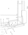
- Figures 2 and 3 are views showing additional detail of a base 140 of the window system 100.
- Fig. 3 some elements have been removed/simplified.
- Fig. 2 is a side view
- Fig. 3 is a perspective view illustrating a channel 145 through which conditioned air can move below the window panes 120, 125.
- the channel 145 also includes an opening or vent 150 through which conditioned air enters the air gap 135 between the panes 120, 125.
- the conditioned air (heated or cooled) can be directed between the panes 120, 125 to defrost the panes 120, 125 in colder climates or prevent condensation in hotter climates.
- the panes 120, 125 of the window system 100 can be thinner than a monolithic single pane, thereby allowing the heated air to more quickly defrost the multiple panes because thinner material is less insulating than thicker material and conducts heat more quickly.
- the window system 100 also includes a hinge 155 to allow one or more of the panes to rotate in relation to the other panes.
- the hinge 155 is at the lower edge of the interior pane 125.
- the use of a hinge 155 to mount the interior pane 125 allows access so that the inner sides of the panes may be cleaned more easily.
- the hinge 155 on the interior pane 125 allows the interior pane 125 to be moved away from the exterior pane 120 to provide access for cleaning tools to be used to clean between the two panes 120, 125.
- Figure 4 is an illustration of the interior pane 125 rotated away from the exterior pane 120 to allow for cleaning of each pane on the sides toward the air gap 135.
- Figure 5 shows a detailed view of the top 160 of the window system 100.
- the interior window 125 is supported by a retaining mechanism 165 that can be released to allow the interior window 125 to swing inward on the hinge 155.
- the retaining mechanism 165 may be a screw 170 that abuts the interior pane 125 and can be tightened and loosened to retain or release the interior pane 125.
- Other types of retaining mechanisms may also be used, including catches, clamps, or the like.
- the window system 100 is intended to provide greater protection in the event of impacts. For example, in the case of objects that may be thrown at the window by the wind, dropping from height, or being release from another piece of equipment or the like.
- the air gap 135 between the panes 120, 125 provides a separation between the panes 120, 125.
- the separation between panes 120, 125 is expected to provide additional protection in that the air gap 135 assists in stopping propagation of cracks initiated in the exterior pane 120 from continuing through the next pane, in this embodiment, the interior pane 125.
- the thickness of monolithic polycarbonate needed to stop chain shot would be 1.25 inches (31.75 mm). This is estimated to be similar to the size needed to meet UL/ANSI 752 level 1 bullet proof testing.
- an embodiment of a dual pane window having two .5 inch (12.7 mm) polycarbonate panes and an air gap of 30 mm was able to pass the UL/ANSI 752 level 1 test.
- the results of the UL/ANSI test are believed to indicate that the window system will also provide greater protection against chain shot.
- the air space between the panes is expected to stop the propagation of the melted pool and prevent a second melted pool from forming in the second pane because the heat of the pool will be reduced/dispersed in the air gap.
- the focus is on a two-pane window but it will be understood that additional panes and air gaps may also be used.
- some panes may be placed adjacent each other without an air gap as long as there is at least one air gap in the window system.
- the size of the panes described and the air gap between panes has been discussed but suitable sizes can be determined based on the application.
- the thickness of each of the panes and the air gap provided may generally be determined based on testing against an approved test such as the UL/ANSI 752 level 1 bullet proof test or the like as may be established from time to time.
- embodiments of the multi-pane window system herein may have panes with a thickness of 5mm, 10mm, 20mm, 30mm or any measurement between these.
- the air gap(s) may be 5mm, 10mm, 15mm, 20mm, 25mm, 30mm or any measurement between these.
- the minimum air gap may be determined by the minimum size needed to allow conditioned air to flow between the panes in order to reduce or prevent fogging or icing.
- panes together with air gaps are also intended to provide some additional benefits. For example, when working with thicker materials, it can be difficult to form the materials into curved or bent shapes. This is particularly true for polycarbonate. By using multiple panes, each pane remains thinner and can still be formed at reasonable cost. For example, a pane of polycarbonate of up to about 15 mm can be curved economically. As such, the use of two panes allows for the polycarbonate to be curved more cost effectively but still provide the level of protection of the thicker single pane that is more difficult/costly to curve. A similar consideration may also apply to the concept of using laminated materials for the window panes because it can be difficult and/or costly to form thicker laminated materials into curved or bent shapes.
- the window panes would first be formed to have a curved shape using known cost effective systems. The panes will then be mounted to provide an air gap between at least two panes.
- the above embodiments relate to a multi-pane window system in which an interior pane can be moved to allow cleaning.
- the panes may be stationary.
Landscapes
- Engineering & Computer Science (AREA)
- Mechanical Engineering (AREA)
- Civil Engineering (AREA)
- Structural Engineering (AREA)
- Mining & Mineral Resources (AREA)
- General Engineering & Computer Science (AREA)
- Laminated Bodies (AREA)
Description
- The embodiments disclosed herein relate to a multi-layer protective window system for non-military heavy equipment and a method for fabricating the same. More particularly, the embodiments herein relate to a protective window for forestry equipment that is intended to protect against chain shot.
- Current heavy equipment and, in particular, forestry equipment, includes curved window designs for operators to view the work area in order to operate tools provided to the heavy equipment.
- Due to debris and moving equipment in the work environment where heavy equipment is used, impacts on the windows can be fairly common. Impacts on the windows can be a danger to the operators. As such, the windows tend to be quite thick and made from stronger materials such as polycarbonate and the like. In some cases, tempered glass may be used but tempered glass is generally not as strong as polycarbonate and may not be appropriate for various applications.
- However, as the material used becomes thicker, it is more and more difficult and costly to form the material into a curved shape for a window. For example, in the forestry industry, curved window designs typically have a maximum 15mm in total thickness of polycarbonate window because the cost of forming thicker materials is too high.
- Further, heavy equipment tends to be used in fairly dirty environments ranging from quite hot to quite cold and this can lead to difficulties in keeping the windows clean and free from frost or condensation.
EP0089850 discloses a method of heating cabs of industrial vehicles used in cold environments in which heated air is driven through at least one window space defined between a pair of generally parallel spaced transparent window panes before entering the cab. Also disclosed is an industrial vehicle for use in cold environments comprising a cab with windows on at least three sides, an air inlet, and an air outlet, the windows having generally parallel spaced inner and outer panes with the interior space vented to the interior of the cab, and means for forcing heated air through the window spaces between the inner and outer panes before entering the cab.DE3430824A1 discloses a vehicle window to be able to exert an influence on the light and heat rays passing through the window. It is proposed to assign the window a cavity essentially adapted to the window pane. With the aid of the cavity (filled with adsorbing media) or with the aid of the walls (polarised, displaceable in relation to one another) forming the cavity, the light and heat permeability can be influenced. - As such, there is a need for an improved protective window for heavy equipment and, in particular, forestry equipment.
- According to one aspect herein, there is provided a protective window system for forestry equipment including at least two window panes of transparent polycarbonate material having a thickness between 10 and 20mm separated by an air gap between 20 and 30 mm, wherein the thickness of each window pane and the size of the air gap is selected such that a larger window pane thickness requires a smaller air gap within the range and the window system meets or exceeds UL/ANSI 752 level 1 testing.
- In still further cases, the at least two window panes may include a plurality of window panes.
- Further, the air gap may include a plurality of air gaps.
- In still further cases, the window system may include a channel for transporting conditioned air and a vent for allowing the conditioned air to enter the air gap.
- In yet still further cases, the window system may include a hinge mechanism for allowing at least one of the at least two window panes to move in relation to another of the at least two window panes.
- According to another aspect herein, there is provided a method of fabricating a protective window system for forestry equipment, the method including: forming at least two polycarbonate window panes to have a curved shape and a thickness between 10 and 20 mm; mounting a first pane of the at least two window panes on an exterior of a cab of the forestry equipment; mounting another pane of the at least two window panes on an interior of the cab; and providing an air gap between 20 and 30 mm between at least two of the at least two panes, wherein at least one of the first pane and another pane are configured to rotate away from the other to allow for cleaning and wherein the thickness of each window pane and the size of the air gap is selected within the specified ranges such that a larger window pane thickness requires a smaller air gap within the range and the window system meets or exceeds UL/ANSI 752 level 1 testing.
- In yet further cases, the at least two window panes may include a plurality of window panes. Further, the air gap may include a plurality of air gaps.
- In still yet further cases, the method may include providing a channel for transporting conditioned air and a vent for allowing the conditioned air to enter the air gap.
- According to yet another aspect herein, there is provided a protective window system for forestry equipment including: at least two window panes of polycarbonate formed with a curved shape and having a thickness between 10 and 20 mm; an air gap between at least two of the at least two window panes between 20 and 30 mm; a channel for transporting conditioned air and a vent for allowing the conditioned air to enter the air gap; and a hinge mechanism for allowing at least one of the at least two window panes to move in relation to another of the at least two window panes, wherein the thickness of each window pane and the size of the air gap is selected from the specified ranges such that a larger window pane thickness requires a smaller air gap within the range and that the window system meets or exceeds UL/ANSI 752 level 1 testing.
- Other aspects and features will become apparent, to those ordinarily skilled in the art, upon review of the following description of some exemplary embodiments.
- Embodiments will now be described, by way of example only, with reference to the attached drawings, in which:
-
Figure 1 shows an embodiment of a protective window system; -
Figure 2 is a side view showing additional detail of a base of the window system ofFigure 1 ; -
Figure 3 is a perspective view showing additional detail of a base of the window system ofFigure 1 , in particular, showing a channel for air flow; -
Figure 4 illustrates a configuration where an interior pane has been moved away from an exterior pane to allow for cleaning of each pane on the sides toward an air gap; and -
Figure 5 shows a detailed view of an embodiment of a top of the window system ofFig. 1 . - In many industrial, construction, mining and forestry environments, heavy machinery is operated by users in cabs on the heavy machinery. The cabs typically have windows for the user to be able to see the surrounding environment. However, these environments may have a risk of debris, equipment, materials coming into contact with and damaging the windows and, in some cases, the users. In the particular example of the forestry industry, high powered chain saws are often attached to a boom on a piece of heavy equipment (for example, a harvesting head, processing head, directional felling head, grapple saw or the like). It has recently been determined that when a high powered chain saw has a chain break, the piece of chain that breaks away (called a chain shot) can be directed at the operator cabin (and the window thereof) at very high speeds similar to a 9mm bullet (1140ft/sec). It is also believed that the chain shot can be spinning at speeds in the range of 400,000rpm. Unlike a bullet or other type of projectile, it appears that this high rotational speed can cause the chain shot to penetrate many types of window material even when another type of projectile might not. It is believed that this penetration is due to the friction heat generated when the rotating chain shot first contacts the window material. The friction heat causes melted material that can continue through a pane of, for example, polycarbonate and allow the chain shot to penetrate the window material.
- The present document describes embodiments of a window system that is intended to protect against projectiles, including chain shot, by using multiple panes having at least one air gap between adjacent panes. In the present embodiments, the air gap between the panes helps to prevent the melted pool of window material from propagating from a first pane into a second or subsequent panes that is placed after the air gap. In order for the chain shot to penetrate multiple panes, a new heated pool of polycarbonate would need to form in the subsequent pane. However, testing has shown that the rotational energy absorbed in the first pane generally reduces the available energy to melt the material in the second pane.
-
Figure 1 shows an embodiment of aprotective window system 100. Thewindow system 100 curves fromtop 105 tobottom 110 around anoperator cab 115 on a piece of heavy equipment (not shown). Thewindow system 100 could also or alternatively be curved along a horizontal direction. As shown inFig. 1 , the example protective window system includes anexterior pane 120 and aninterior pane 125 of transparent material placed adjacent to one another between anoperator station 130 and the outside of thecab 115. There is anair gap 135 provided between the exterior andinterior windows panes interior window panes - The transparent window material will generally be polycarbonate or similar but could also be other suitable materials having similar functionality.
-
Figures 2 and3 are views showing additional detail of abase 140 of thewindow system 100. InFig. 3 , some elements have been removed/simplified.Fig. 2 is a side view andFig. 3 is a perspective view illustrating achannel 145 through which conditioned air can move below thewindow panes channel 145 also includes an opening orvent 150 through which conditioned air enters theair gap 135 between thepanes panes panes panes window system 100 can be thinner than a monolithic single pane, thereby allowing the heated air to more quickly defrost the multiple panes because thinner material is less insulating than thicker material and conducts heat more quickly. - As shown in
Figs 2 and3 , thewindow system 100 also includes ahinge 155 to allow one or more of the panes to rotate in relation to the other panes. In the embodiment shown inFigs. 2 and3 , thehinge 155 is at the lower edge of theinterior pane 125. The use of ahinge 155 to mount the interior pane 125 (although either one of the window panes could be hinged) allows access so that the inner sides of the panes may be cleaned more easily. In particular, thehinge 155 on theinterior pane 125 allows theinterior pane 125 to be moved away from theexterior pane 120 to provide access for cleaning tools to be used to clean between the twopanes Figure 4 is an illustration of theinterior pane 125 rotated away from theexterior pane 120 to allow for cleaning of each pane on the sides toward theair gap 135. -
Figure 5 shows a detailed view of the top 160 of thewindow system 100. In this embodiment, theinterior window 125 is supported by aretaining mechanism 165 that can be released to allow theinterior window 125 to swing inward on thehinge 155. In particular, theretaining mechanism 165 may be ascrew 170 that abuts theinterior pane 125 and can be tightened and loosened to retain or release theinterior pane 125. Other types of retaining mechanisms may also be used, including catches, clamps, or the like. - The
window system 100 is intended to provide greater protection in the event of impacts. For example, in the case of objects that may be thrown at the window by the wind, dropping from height, or being release from another piece of equipment or the like. In the case of any impacts, theair gap 135 between thepanes panes panes air gap 135 assists in stopping propagation of cracks initiated in theexterior pane 120 from continuing through the next pane, in this embodiment, theinterior pane 125. - In a particular example from the forestry industry, it has been estimated that the thickness of monolithic polycarbonate needed to stop chain shot would be 1.25 inches (31.75 mm). This is estimated to be similar to the size needed to meet UL/ANSI 752 level 1 bullet proof testing. In a test, an embodiment of a dual pane window having two .5 inch (12.7 mm) polycarbonate panes and an air gap of 30 mm was able to pass the UL/ANSI 752 level 1 test.
- While embodiments of the improved window system as described herein have not been tested with regard to chain shot as yet, the results of the UL/ANSI test are believed to indicate that the window system will also provide greater protection against chain shot. In particular, the air space between the panes is expected to stop the propagation of the melted pool and prevent a second melted pool from forming in the second pane because the heat of the pool will be reduced/dispersed in the air gap.
- In the above embodiment, the focus is on a two-pane window but it will be understood that additional panes and air gaps may also be used. In some multi-pane cases, some panes may be placed adjacent each other without an air gap as long as there is at least one air gap in the window system. Further, the size of the panes described and the air gap between panes has been discussed but suitable sizes can be determined based on the application. Further, the thickness of each of the panes and the air gap provided may generally be determined based on testing against an approved test such as the UL/ANSI 752 level 1 bullet proof test or the like as may be established from time to time. As long as the window system meets the appropriate standard, embodiments of the multi-pane window system herein may have panes with a thickness of 5mm, 10mm, 20mm, 30mm or any measurement between these. The air gap(s) may be 5mm, 10mm, 15mm, 20mm, 25mm, 30mm or any measurement between these. In some embodiments, in addition to the considerations above, the minimum air gap may be determined by the minimum size needed to allow conditioned air to flow between the panes in order to reduce or prevent fogging or icing.
- The use of multiple monolithic panes together with air gaps is also intended to provide some additional benefits. For example, when working with thicker materials, it can be difficult to form the materials into curved or bent shapes. This is particularly true for polycarbonate. By using multiple panes, each pane remains thinner and can still be formed at reasonable cost. For example, a pane of polycarbonate of up to about 15 mm can be curved economically. As such, the use of two panes allows for the polycarbonate to be curved more cost effectively but still provide the level of protection of the thicker single pane that is more difficult/costly to curve. A similar consideration may also apply to the concept of using laminated materials for the window panes because it can be difficult and/or costly to form thicker laminated materials into curved or bent shapes.
- In an embodiment of fabricating embodiments of the window system herein, the window panes would first be formed to have a curved shape using known cost effective systems. The panes will then be mounted to provide an air gap between at least two panes.
- The above embodiments relate to a multi-pane window system in which an interior pane can be moved to allow cleaning. In other embodiments, the panes may be stationary.
Claims (14)
- A protective window system (100) for forestry equipment comprising at least two window panes (120, 125) of transparent polycarbonate material having a thickness between 10 and 20 mm separated by an air gap (135) between 20 and 30 mm, wherein the thickness of each window pane and the size of the air gap is selected such that the window system meets or exceeds UL/ANSI 752 level 1 testing.
- A protective window system (100) according to claim 1, wherein the at least two window panes (120, 125) comprises a plurality of window panes.
- A protective window system (100) according to claim 2, wherein the air gap (135) comprises a plurality of air gaps.
- A protective window system (100) according to any one of claims 1 to 3, further comprising a channel (145) for transporting conditioned air and a vent (150) for allowing the conditioned air to enter the air gap.
- A protective window system (100) according to any one of claims 1 to 4, further comprising a hinge mechanism (155) for allowing at least one of the at least two window panes to move in relation to another of the at least two window panes.
- A protective window system (100) according to any one of claims 1 to 5, wherein the thickness of each of the two window panes (120, 125) is 12.7 mm and the air gap (135) is 30 mm.
- A protective window system (100) according to any one of claims 1 to 6, wherein the meets or exceeds UL/ANSI 752 level 1 testing must be when impacted with chain shot.
- A method of fabricating a protective window system (100) for forestry equipment, the method comprising:forming at least two polycarbonate window panes (120, 125) to have a curved shape and a thickness between 10 and 20 mm;mounting a first pane (120) of the at least two window panes on an exterior of a cab of the forestry equipment;mounting another pane (125) of the at least two window panes on an interior of the cab; andproviding an air gap (135) between 20 and 30 mm between at least two of the at least two panes,wherein at least one of the first pane and another pane are configured to rotate away from the other to allow for cleaning and wherein the thickness of each window pane and the size of the air gap is selected within the specified ranges such that the window system meets or exceeds UL/ANSI 752 level 1 testing.
- A method according to claim 8, wherein the at least two window panes (120, 125) comprises a plurality of window panes.
- A method according to claim 9, wherein the air gap (135) comprises a plurality of air gaps.
- A method according to any one of claims 8 to 10, further comprising providing a channel (145) for transporting conditioned air and a vent (150) for allowing the conditioned air to enter the air gap.
- A protective window system (100) for forestry equipment according to any one of claims 1 to 7, comprising:said at least two window panes (120, 125) of polycarbonate, formed with a curved shapea channel (145) for transporting conditioned air and a vent (150) for allowing the conditioned air to enter the air gap; anda hinge mechanism (155) for allowing at least one of the at least two window panes to move in relation to another of the at least two window panes.
- A protective window system (100) according to claim 12, wherein the thickness of each of the two window panes (120, 125) is 12.7 mm and the air gap (135) is 30 mm.
- A protective window system (100) according to any one of claims 12 and 13, wherein the meets or exceeds UL/ANSI 752 level 1 testing must be when impacted with chain shot.
Applications Claiming Priority (2)
| Application Number | Priority Date | Filing Date | Title |
|---|---|---|---|
| US201662407220P | 2016-10-12 | 2016-10-12 | |
| PCT/CA2017/051212 WO2018068141A1 (en) | 2016-10-12 | 2017-10-12 | Multi-layer protective window system for non-military heavy equipment and method for fabricating same |
Publications (3)
| Publication Number | Publication Date |
|---|---|
| EP3526511A1 EP3526511A1 (en) | 2019-08-21 |
| EP3526511A4 EP3526511A4 (en) | 2020-06-10 |
| EP3526511B1 true EP3526511B1 (en) | 2024-06-12 |
Family
ID=61905043
Family Applications (1)
| Application Number | Title | Priority Date | Filing Date |
|---|---|---|---|
| EP17859848.8A Active EP3526511B1 (en) | 2016-10-12 | 2017-10-12 | Multi-layer protective window system for non-military heavy equipment and method for fabricating same |
Country Status (4)
| Country | Link |
|---|---|
| US (1) | US20190202272A1 (en) |
| EP (1) | EP3526511B1 (en) |
| CA (1) | CA3035811A1 (en) |
| WO (1) | WO2018068141A1 (en) |
Families Citing this family (1)
| Publication number | Priority date | Publication date | Assignee | Title |
|---|---|---|---|---|
| CL2023002441A1 (en) * | 2022-08-19 | 2024-03-01 | Joy Global Surface Mining Inc | Operator's cabin and operator window |
Family Cites Families (9)
| Publication number | Priority date | Publication date | Assignee | Title |
|---|---|---|---|---|
| SE416464B (en) * | 1975-05-31 | 1981-01-05 | Bfg Glassgroup | RESISTANCE TO MULTIPLE RESISTANCE |
| GB2116692B (en) * | 1982-03-19 | 1985-09-25 | Montgomerie Reid Ltd | Improvements in cab construction for industrial vehicles |
| DE3430824A1 (en) * | 1984-08-22 | 1986-03-06 | Siegfried 5042 Erftstadt Henschke | Sunscreen |
| DE4038415C2 (en) * | 1990-12-01 | 1994-11-03 | Autz & Herrmann Maschf | Clear window |
| FR2684131B1 (en) * | 1991-11-25 | 1998-10-02 | Standard Products Atlantic | METHOD FOR MANUFACTURING A FLUSHING DOUBLE GLAZING FOR A MOTOR VEHICLE. |
| US8789324B2 (en) * | 2007-02-13 | 2014-07-29 | Henry M. Hay | Impact resistant window |
| DE102009030057A1 (en) * | 2009-06-22 | 2011-01-05 | Köster, Helmut, Dr.-Ing. | Double-leaf facade element e.g. coupled window, has air tube actively cooled by cooling element and cooled and humidified by inflow air, where cooling element is controlled by temperature controller |
| WO2012103102A1 (en) * | 2011-01-26 | 2012-08-02 | Dow Corning Corporation | Assemblies for a structure |
| EP2667143B1 (en) * | 2012-05-21 | 2015-03-18 | ISOCLIMA S.p.A. | Pane construction and corresponding bullet proof window |
-
2017
- 2017-10-12 CA CA3035811A patent/CA3035811A1/en active Pending
- 2017-10-12 EP EP17859848.8A patent/EP3526511B1/en active Active
- 2017-10-12 WO PCT/CA2017/051212 patent/WO2018068141A1/en not_active Ceased
-
2019
- 2019-03-06 US US16/294,379 patent/US20190202272A1/en not_active Abandoned
Also Published As
| Publication number | Publication date |
|---|---|
| EP3526511A4 (en) | 2020-06-10 |
| US20190202272A1 (en) | 2019-07-04 |
| CA3035811A1 (en) | 2018-04-19 |
| EP3526511A1 (en) | 2019-08-21 |
| WO2018068141A1 (en) | 2018-04-19 |
Similar Documents
| Publication | Publication Date | Title |
|---|---|---|
| US5452641A (en) | Transparent armor piercing protection system | |
| CN104722934B (en) | Laser machine device | |
| US5161055A (en) | Rotating window | |
| US12344518B2 (en) | Telehandler with improved cab | |
| AU2010203090A1 (en) | Transparent ceramic composite | |
| FR2640194A1 (en) | COMPOSITE GLAZING | |
| EP2667143B1 (en) | Pane construction and corresponding bullet proof window | |
| EP3526511B1 (en) | Multi-layer protective window system for non-military heavy equipment and method for fabricating same | |
| GB2443826A (en) | Window and combined defence shutter and blind | |
| KR102200587B1 (en) | Protection shelter for against | |
| EP1500537B1 (en) | Glass pane for vehicles | |
| KR102347060B1 (en) | Laser machining machine system having a portion of a laser protective wall, which is realized as lamellar region | |
| US7832325B1 (en) | Ballistic armor shield for hatch area of armored vehicle | |
| US20080163799A1 (en) | Safety workbench having easy-to-clean front pane | |
| BR112016025947B1 (en) | explosion-proof bulletproof device | |
| US20030190439A1 (en) | Transparent armor structure | |
| KR102143646B1 (en) | Bulletproof and explosion-proof glass production system | |
| US9550343B2 (en) | Laminated transparency with controlled failure and method of making the same | |
| BR112016025636B1 (en) | BULLET AND BURST RESISTANT WINDOW AND ASSOCIATED APPLIANCE | |
| JP7388935B2 (en) | Indoor panel bodies and indoor panel structures | |
| RU2175946C2 (en) | Tower crane cabin | |
| US12312224B2 (en) | Telehandler provided with improved cab | |
| EP2746080B1 (en) | A roof panel | |
| JP2013136473A (en) | Fire protection double-glazed glass | |
| CA2086370A1 (en) | Shatterproof laminated glazing |
Legal Events
| Date | Code | Title | Description |
|---|---|---|---|
| STAA | Information on the status of an ep patent application or granted ep patent |
Free format text: STATUS: THE INTERNATIONAL PUBLICATION HAS BEEN MADE |
|
| PUAI | Public reference made under article 153(3) epc to a published international application that has entered the european phase |
Free format text: ORIGINAL CODE: 0009012 |
|
| STAA | Information on the status of an ep patent application or granted ep patent |
Free format text: STATUS: REQUEST FOR EXAMINATION WAS MADE |
|
| 17P | Request for examination filed |
Effective date: 20190311 |
|
| AK | Designated contracting states |
Kind code of ref document: A1 Designated state(s): AL AT BE BG CH CY CZ DE DK EE ES FI FR GB GR HR HU IE IS IT LI LT LU LV MC MK MT NL NO PL PT RO RS SE SI SK SM TR |
|
| AX | Request for extension of the european patent |
Extension state: BA ME |
|
| DAV | Request for validation of the european patent (deleted) | ||
| DAX | Request for extension of the european patent (deleted) | ||
| A4 | Supplementary search report drawn up and despatched |
Effective date: 20200512 |
|
| RIC1 | Information provided on ipc code assigned before grant |
Ipc: F16P 1/00 20060101AFI20200506BHEP Ipc: E02F 9/16 20060101ALI20200506BHEP Ipc: B60J 1/06 20060101ALI20200506BHEP Ipc: B60J 1/00 20060101ALI20200506BHEP |
|
| STAA | Information on the status of an ep patent application or granted ep patent |
Free format text: STATUS: EXAMINATION IS IN PROGRESS |
|
| 17Q | First examination report despatched |
Effective date: 20210414 |
|
| GRAP | Despatch of communication of intention to grant a patent |
Free format text: ORIGINAL CODE: EPIDOSNIGR1 |
|
| STAA | Information on the status of an ep patent application or granted ep patent |
Free format text: STATUS: GRANT OF PATENT IS INTENDED |
|
| INTG | Intention to grant announced |
Effective date: 20240105 |
|
| GRAS | Grant fee paid |
Free format text: ORIGINAL CODE: EPIDOSNIGR3 |
|
| GRAA | (expected) grant |
Free format text: ORIGINAL CODE: 0009210 |
|
| STAA | Information on the status of an ep patent application or granted ep patent |
Free format text: STATUS: THE PATENT HAS BEEN GRANTED |
|
| AK | Designated contracting states |
Kind code of ref document: B1 Designated state(s): AL AT BE BG CH CY CZ DE DK EE ES FI FR GB GR HR HU IE IS IT LI LT LU LV MC MK MT NL NO PL PT RO RS SE SI SK SM TR |
|
| REG | Reference to a national code |
Ref country code: GB Ref legal event code: FG4D |
|
| REG | Reference to a national code |
Ref country code: CH Ref legal event code: EP |
|
| REG | Reference to a national code |
Ref country code: DE Ref legal event code: R096 Ref document number: 602017082596 Country of ref document: DE |
|
| REG | Reference to a national code |
Ref country code: IE Ref legal event code: FG4D |
|
| PG25 | Lapsed in a contracting state [announced via postgrant information from national office to epo] |
Ref country code: BG Free format text: LAPSE BECAUSE OF FAILURE TO SUBMIT A TRANSLATION OF THE DESCRIPTION OR TO PAY THE FEE WITHIN THE PRESCRIBED TIME-LIMIT Effective date: 20240612 |
|
| PG25 | Lapsed in a contracting state [announced via postgrant information from national office to epo] |
Ref country code: FI Free format text: LAPSE BECAUSE OF FAILURE TO SUBMIT A TRANSLATION OF THE DESCRIPTION OR TO PAY THE FEE WITHIN THE PRESCRIBED TIME-LIMIT Effective date: 20240612 Ref country code: HR Free format text: LAPSE BECAUSE OF FAILURE TO SUBMIT A TRANSLATION OF THE DESCRIPTION OR TO PAY THE FEE WITHIN THE PRESCRIBED TIME-LIMIT Effective date: 20240612 |
|
| REG | Reference to a national code |
Ref country code: LT Ref legal event code: MG9D |
|
| PG25 | Lapsed in a contracting state [announced via postgrant information from national office to epo] |
Ref country code: GR Free format text: LAPSE BECAUSE OF FAILURE TO SUBMIT A TRANSLATION OF THE DESCRIPTION OR TO PAY THE FEE WITHIN THE PRESCRIBED TIME-LIMIT Effective date: 20240913 |
|
| REG | Reference to a national code |
Ref country code: NL Ref legal event code: MP Effective date: 20240612 |
|
| PG25 | Lapsed in a contracting state [announced via postgrant information from national office to epo] |
Ref country code: ES Free format text: LAPSE BECAUSE OF FAILURE TO SUBMIT A TRANSLATION OF THE DESCRIPTION OR TO PAY THE FEE WITHIN THE PRESCRIBED TIME-LIMIT Effective date: 20240612 |
|
| PG25 | Lapsed in a contracting state [announced via postgrant information from national office to epo] |
Ref country code: LV Free format text: LAPSE BECAUSE OF FAILURE TO SUBMIT A TRANSLATION OF THE DESCRIPTION OR TO PAY THE FEE WITHIN THE PRESCRIBED TIME-LIMIT Effective date: 20240612 |
|
| PG25 | Lapsed in a contracting state [announced via postgrant information from national office to epo] |
Ref country code: NO Free format text: LAPSE BECAUSE OF FAILURE TO SUBMIT A TRANSLATION OF THE DESCRIPTION OR TO PAY THE FEE WITHIN THE PRESCRIBED TIME-LIMIT Effective date: 20240912 Ref country code: LV Free format text: LAPSE BECAUSE OF FAILURE TO SUBMIT A TRANSLATION OF THE DESCRIPTION OR TO PAY THE FEE WITHIN THE PRESCRIBED TIME-LIMIT Effective date: 20240612 Ref country code: HR Free format text: LAPSE BECAUSE OF FAILURE TO SUBMIT A TRANSLATION OF THE DESCRIPTION OR TO PAY THE FEE WITHIN THE PRESCRIBED TIME-LIMIT Effective date: 20240612 Ref country code: GR Free format text: LAPSE BECAUSE OF FAILURE TO SUBMIT A TRANSLATION OF THE DESCRIPTION OR TO PAY THE FEE WITHIN THE PRESCRIBED TIME-LIMIT Effective date: 20240913 Ref country code: FI Free format text: LAPSE BECAUSE OF FAILURE TO SUBMIT A TRANSLATION OF THE DESCRIPTION OR TO PAY THE FEE WITHIN THE PRESCRIBED TIME-LIMIT Effective date: 20240612 Ref country code: ES Free format text: LAPSE BECAUSE OF FAILURE TO SUBMIT A TRANSLATION OF THE DESCRIPTION OR TO PAY THE FEE WITHIN THE PRESCRIBED TIME-LIMIT Effective date: 20240612 Ref country code: BG Free format text: LAPSE BECAUSE OF FAILURE TO SUBMIT A TRANSLATION OF THE DESCRIPTION OR TO PAY THE FEE WITHIN THE PRESCRIBED TIME-LIMIT Effective date: 20240612 Ref country code: RS Free format text: LAPSE BECAUSE OF FAILURE TO SUBMIT A TRANSLATION OF THE DESCRIPTION OR TO PAY THE FEE WITHIN THE PRESCRIBED TIME-LIMIT Effective date: 20240912 |
|
| PG25 | Lapsed in a contracting state [announced via postgrant information from national office to epo] |
Ref country code: NL Free format text: LAPSE BECAUSE OF FAILURE TO SUBMIT A TRANSLATION OF THE DESCRIPTION OR TO PAY THE FEE WITHIN THE PRESCRIBED TIME-LIMIT Effective date: 20240612 |
|
| REG | Reference to a national code |
Ref country code: AT Ref legal event code: MK05 Ref document number: 1694544 Country of ref document: AT Kind code of ref document: T Effective date: 20240612 |
|
| PG25 | Lapsed in a contracting state [announced via postgrant information from national office to epo] |
Ref country code: NL Free format text: LAPSE BECAUSE OF FAILURE TO SUBMIT A TRANSLATION OF THE DESCRIPTION OR TO PAY THE FEE WITHIN THE PRESCRIBED TIME-LIMIT Effective date: 20240612 |
|
| PG25 | Lapsed in a contracting state [announced via postgrant information from national office to epo] |
Ref country code: PT Free format text: LAPSE BECAUSE OF FAILURE TO SUBMIT A TRANSLATION OF THE DESCRIPTION OR TO PAY THE FEE WITHIN THE PRESCRIBED TIME-LIMIT Effective date: 20241014 |
|
| PG25 | Lapsed in a contracting state [announced via postgrant information from national office to epo] |
Ref country code: PT Free format text: LAPSE BECAUSE OF FAILURE TO SUBMIT A TRANSLATION OF THE DESCRIPTION OR TO PAY THE FEE WITHIN THE PRESCRIBED TIME-LIMIT Effective date: 20241014 |
|
| PG25 | Lapsed in a contracting state [announced via postgrant information from national office to epo] |
Ref country code: PL Free format text: LAPSE BECAUSE OF FAILURE TO SUBMIT A TRANSLATION OF THE DESCRIPTION OR TO PAY THE FEE WITHIN THE PRESCRIBED TIME-LIMIT Effective date: 20240612 |
|
| PG25 | Lapsed in a contracting state [announced via postgrant information from national office to epo] |
Ref country code: EE Free format text: LAPSE BECAUSE OF FAILURE TO SUBMIT A TRANSLATION OF THE DESCRIPTION OR TO PAY THE FEE WITHIN THE PRESCRIBED TIME-LIMIT Effective date: 20240612 |
|
| PG25 | Lapsed in a contracting state [announced via postgrant information from national office to epo] |
Ref country code: AT Free format text: LAPSE BECAUSE OF FAILURE TO SUBMIT A TRANSLATION OF THE DESCRIPTION OR TO PAY THE FEE WITHIN THE PRESCRIBED TIME-LIMIT Effective date: 20240612 Ref country code: IS Free format text: LAPSE BECAUSE OF FAILURE TO SUBMIT A TRANSLATION OF THE DESCRIPTION OR TO PAY THE FEE WITHIN THE PRESCRIBED TIME-LIMIT Effective date: 20241012 |
|
| PG25 | Lapsed in a contracting state [announced via postgrant information from national office to epo] |
Ref country code: CZ Free format text: LAPSE BECAUSE OF FAILURE TO SUBMIT A TRANSLATION OF THE DESCRIPTION OR TO PAY THE FEE WITHIN THE PRESCRIBED TIME-LIMIT Effective date: 20240612 |
|
| PG25 | Lapsed in a contracting state [announced via postgrant information from national office to epo] |
Ref country code: RO Free format text: LAPSE BECAUSE OF FAILURE TO SUBMIT A TRANSLATION OF THE DESCRIPTION OR TO PAY THE FEE WITHIN THE PRESCRIBED TIME-LIMIT Effective date: 20240612 Ref country code: SK Free format text: LAPSE BECAUSE OF FAILURE TO SUBMIT A TRANSLATION OF THE DESCRIPTION OR TO PAY THE FEE WITHIN THE PRESCRIBED TIME-LIMIT Effective date: 20240612 |
|
| PG25 | Lapsed in a contracting state [announced via postgrant information from national office to epo] |
Ref country code: SM Free format text: LAPSE BECAUSE OF FAILURE TO SUBMIT A TRANSLATION OF THE DESCRIPTION OR TO PAY THE FEE WITHIN THE PRESCRIBED TIME-LIMIT Effective date: 20240612 |
|
| PG25 | Lapsed in a contracting state [announced via postgrant information from national office to epo] |
Ref country code: SM Free format text: LAPSE BECAUSE OF FAILURE TO SUBMIT A TRANSLATION OF THE DESCRIPTION OR TO PAY THE FEE WITHIN THE PRESCRIBED TIME-LIMIT Effective date: 20240612 Ref country code: SK Free format text: LAPSE BECAUSE OF FAILURE TO SUBMIT A TRANSLATION OF THE DESCRIPTION OR TO PAY THE FEE WITHIN THE PRESCRIBED TIME-LIMIT Effective date: 20240612 Ref country code: RO Free format text: LAPSE BECAUSE OF FAILURE TO SUBMIT A TRANSLATION OF THE DESCRIPTION OR TO PAY THE FEE WITHIN THE PRESCRIBED TIME-LIMIT Effective date: 20240612 Ref country code: PL Free format text: LAPSE BECAUSE OF FAILURE TO SUBMIT A TRANSLATION OF THE DESCRIPTION OR TO PAY THE FEE WITHIN THE PRESCRIBED TIME-LIMIT Effective date: 20240612 Ref country code: IS Free format text: LAPSE BECAUSE OF FAILURE TO SUBMIT A TRANSLATION OF THE DESCRIPTION OR TO PAY THE FEE WITHIN THE PRESCRIBED TIME-LIMIT Effective date: 20241012 Ref country code: EE Free format text: LAPSE BECAUSE OF FAILURE TO SUBMIT A TRANSLATION OF THE DESCRIPTION OR TO PAY THE FEE WITHIN THE PRESCRIBED TIME-LIMIT Effective date: 20240612 Ref country code: CZ Free format text: LAPSE BECAUSE OF FAILURE TO SUBMIT A TRANSLATION OF THE DESCRIPTION OR TO PAY THE FEE WITHIN THE PRESCRIBED TIME-LIMIT Effective date: 20240612 Ref country code: AT Free format text: LAPSE BECAUSE OF FAILURE TO SUBMIT A TRANSLATION OF THE DESCRIPTION OR TO PAY THE FEE WITHIN THE PRESCRIBED TIME-LIMIT Effective date: 20240612 |
|
| PG25 | Lapsed in a contracting state [announced via postgrant information from national office to epo] |
Ref country code: IT Free format text: LAPSE BECAUSE OF FAILURE TO SUBMIT A TRANSLATION OF THE DESCRIPTION OR TO PAY THE FEE WITHIN THE PRESCRIBED TIME-LIMIT Effective date: 20240612 |
|
| REG | Reference to a national code |
Ref country code: DE Ref legal event code: R097 Ref document number: 602017082596 Country of ref document: DE |
|
| PG25 | Lapsed in a contracting state [announced via postgrant information from national office to epo] |
Ref country code: DK Free format text: LAPSE BECAUSE OF FAILURE TO SUBMIT A TRANSLATION OF THE DESCRIPTION OR TO PAY THE FEE WITHIN THE PRESCRIBED TIME-LIMIT Effective date: 20240612 |
|
| PLBE | No opposition filed within time limit |
Free format text: ORIGINAL CODE: 0009261 |
|
| STAA | Information on the status of an ep patent application or granted ep patent |
Free format text: STATUS: NO OPPOSITION FILED WITHIN TIME LIMIT |
|
| 26N | No opposition filed |
Effective date: 20250313 |
|
| REG | Reference to a national code |
Ref country code: CH Ref legal event code: PL |
|
| PG25 | Lapsed in a contracting state [announced via postgrant information from national office to epo] |
Ref country code: MC Free format text: LAPSE BECAUSE OF FAILURE TO SUBMIT A TRANSLATION OF THE DESCRIPTION OR TO PAY THE FEE WITHIN THE PRESCRIBED TIME-LIMIT Effective date: 20240612 |
|
| PG25 | Lapsed in a contracting state [announced via postgrant information from national office to epo] |
Ref country code: BE Free format text: LAPSE BECAUSE OF NON-PAYMENT OF DUE FEES Effective date: 20241031 Ref country code: LU Free format text: LAPSE BECAUSE OF NON-PAYMENT OF DUE FEES Effective date: 20241012 |
|
| PG25 | Lapsed in a contracting state [announced via postgrant information from national office to epo] |
Ref country code: CH Free format text: LAPSE BECAUSE OF NON-PAYMENT OF DUE FEES Effective date: 20241031 |
|
| REG | Reference to a national code |
Ref country code: BE Ref legal event code: MM Effective date: 20241031 |
|
| PG25 | Lapsed in a contracting state [announced via postgrant information from national office to epo] |
Ref country code: SE Free format text: LAPSE BECAUSE OF FAILURE TO SUBMIT A TRANSLATION OF THE DESCRIPTION OR TO PAY THE FEE WITHIN THE PRESCRIBED TIME-LIMIT Effective date: 20240612 |
|
| PG25 | Lapsed in a contracting state [announced via postgrant information from national office to epo] |
Ref country code: IE Free format text: LAPSE BECAUSE OF NON-PAYMENT OF DUE FEES Effective date: 20241012 |
|
| PGFP | Annual fee paid to national office [announced via postgrant information from national office to epo] |
Ref country code: DE Payment date: 20251024 Year of fee payment: 9 |
|
| PGFP | Annual fee paid to national office [announced via postgrant information from national office to epo] |
Ref country code: GB Payment date: 20251003 Year of fee payment: 9 |
|
| PGFP | Annual fee paid to national office [announced via postgrant information from national office to epo] |
Ref country code: FR Payment date: 20251003 Year of fee payment: 9 |
|
| PG25 | Lapsed in a contracting state [announced via postgrant information from national office to epo] |
Ref country code: CY Free format text: LAPSE BECAUSE OF FAILURE TO SUBMIT A TRANSLATION OF THE DESCRIPTION OR TO PAY THE FEE WITHIN THE PRESCRIBED TIME-LIMIT; INVALID AB INITIO Effective date: 20171012 |
|
| PG25 | Lapsed in a contracting state [announced via postgrant information from national office to epo] |
Ref country code: HU Free format text: LAPSE BECAUSE OF FAILURE TO SUBMIT A TRANSLATION OF THE DESCRIPTION OR TO PAY THE FEE WITHIN THE PRESCRIBED TIME-LIMIT; INVALID AB INITIO Effective date: 20171012 |