EP3526504B1 - High performance aramid braided hose - Google Patents
High performance aramid braided hose Download PDFInfo
- Publication number
- EP3526504B1 EP3526504B1 EP17787830.3A EP17787830A EP3526504B1 EP 3526504 B1 EP3526504 B1 EP 3526504B1 EP 17787830 A EP17787830 A EP 17787830A EP 3526504 B1 EP3526504 B1 EP 3526504B1
- Authority
- EP
- European Patent Office
- Prior art keywords
- braid
- hose assembly
- hose
- nipple
- modulus
- Prior art date
- Legal status (The legal status is an assumption and is not a legal conclusion. Google has not performed a legal analysis and makes no representation as to the accuracy of the status listed.)
- Active
Links
Images


Classifications
-
- F—MECHANICAL ENGINEERING; LIGHTING; HEATING; WEAPONS; BLASTING
- F16—ENGINEERING ELEMENTS AND UNITS; GENERAL MEASURES FOR PRODUCING AND MAINTAINING EFFECTIVE FUNCTIONING OF MACHINES OR INSTALLATIONS; THERMAL INSULATION IN GENERAL
- F16L—PIPES; JOINTS OR FITTINGS FOR PIPES; SUPPORTS FOR PIPES, CABLES OR PROTECTIVE TUBING; MEANS FOR THERMAL INSULATION IN GENERAL
- F16L11/00—Hoses, i.e. flexible pipes
- F16L11/04—Hoses, i.e. flexible pipes made of rubber or flexible plastics
- F16L11/08—Hoses, i.e. flexible pipes made of rubber or flexible plastics with reinforcements embedded in the wall
- F16L11/085—Hoses, i.e. flexible pipes made of rubber or flexible plastics with reinforcements embedded in the wall comprising one or more braided layers
- F16L11/086—Hoses, i.e. flexible pipes made of rubber or flexible plastics with reinforcements embedded in the wall comprising one or more braided layers two layers
-
- F—MECHANICAL ENGINEERING; LIGHTING; HEATING; WEAPONS; BLASTING
- F16—ENGINEERING ELEMENTS AND UNITS; GENERAL MEASURES FOR PRODUCING AND MAINTAINING EFFECTIVE FUNCTIONING OF MACHINES OR INSTALLATIONS; THERMAL INSULATION IN GENERAL
- F16L—PIPES; JOINTS OR FITTINGS FOR PIPES; SUPPORTS FOR PIPES, CABLES OR PROTECTIVE TUBING; MEANS FOR THERMAL INSULATION IN GENERAL
- F16L11/00—Hoses, i.e. flexible pipes
- F16L11/04—Hoses, i.e. flexible pipes made of rubber or flexible plastics
- F16L11/08—Hoses, i.e. flexible pipes made of rubber or flexible plastics with reinforcements embedded in the wall
- F16L11/085—Hoses, i.e. flexible pipes made of rubber or flexible plastics with reinforcements embedded in the wall comprising one or more braided layers
- F16L11/087—Hoses, i.e. flexible pipes made of rubber or flexible plastics with reinforcements embedded in the wall comprising one or more braided layers three or more layers
-
- F—MECHANICAL ENGINEERING; LIGHTING; HEATING; WEAPONS; BLASTING
- F16—ENGINEERING ELEMENTS AND UNITS; GENERAL MEASURES FOR PRODUCING AND MAINTAINING EFFECTIVE FUNCTIONING OF MACHINES OR INSTALLATIONS; THERMAL INSULATION IN GENERAL
- F16L—PIPES; JOINTS OR FITTINGS FOR PIPES; SUPPORTS FOR PIPES, CABLES OR PROTECTIVE TUBING; MEANS FOR THERMAL INSULATION IN GENERAL
- F16L33/00—Arrangements for connecting hoses to rigid members; Rigid hose-connectors, i.e. single members engaging both hoses
- F16L33/20—Undivided rings, sleeves, or like members contracted on the hose or expanded inside the hose by means of tools; Arrangements using such members
- F16L33/207—Undivided rings, sleeves, or like members contracted on the hose or expanded inside the hose by means of tools; Arrangements using such members only a sleeve being contracted on the hose
- F16L33/2071—Undivided rings, sleeves, or like members contracted on the hose or expanded inside the hose by means of tools; Arrangements using such members only a sleeve being contracted on the hose the sleeve being a separate connecting member
- F16L33/2073—Undivided rings, sleeves, or like members contracted on the hose or expanded inside the hose by means of tools; Arrangements using such members only a sleeve being contracted on the hose the sleeve being a separate connecting member directly connected to the rigid member
- F16L33/2076—Undivided rings, sleeves, or like members contracted on the hose or expanded inside the hose by means of tools; Arrangements using such members only a sleeve being contracted on the hose the sleeve being a separate connecting member directly connected to the rigid member by plastic deformation
-
- F—MECHANICAL ENGINEERING; LIGHTING; HEATING; WEAPONS; BLASTING
- F16—ENGINEERING ELEMENTS AND UNITS; GENERAL MEASURES FOR PRODUCING AND MAINTAINING EFFECTIVE FUNCTIONING OF MACHINES OR INSTALLATIONS; THERMAL INSULATION IN GENERAL
- F16L—PIPES; JOINTS OR FITTINGS FOR PIPES; SUPPORTS FOR PIPES, CABLES OR PROTECTIVE TUBING; MEANS FOR THERMAL INSULATION IN GENERAL
- F16L33/00—Arrangements for connecting hoses to rigid members; Rigid hose-connectors, i.e. single members engaging both hoses
- F16L33/24—Arrangements for connecting hoses to rigid members; Rigid hose-connectors, i.e. single members engaging both hoses with parts screwed directly on or into the hose
Definitions
- the present invention relates generally to hose configurations suitable for use in environments in which hoses may be subject to high pressures, such as for example in deep subsea applications or comparable.
- Hydraulic and other hoses may be subjected to substantial pressures in certain environments of use.
- hydraulic and other hoses may be employed in deep undersea oil and gas drilling operations, including in blow-off preventers that act as a safety feature that closes off a drilling operation in case of a catastrophic failure.
- Other undersea hose applications may include hydraulic hoses, flying leads, hotline hoses, and hoses used with subsea umbilicals.
- Hoses in undersea oil and gas drilling operations may experience enormous high external pressures, sometimes at 5000 psi and above, where 1 psi is about 0.07 bars (i.e. 1000 psi is about 70 bars), and often at pressures of 8000-9000 psi. At such pressures, there is a danger of hose failure if the hose is not designed to accommodate such pressure levels. Accordingly, hoses need to be collapse resistant when subjected to such pressures, and also must be highly impulse fatigue resistant to accommodate the impulse pressures of the fluids being transported through the hoses with high flow rates.
- US Patent Publication no. US-2011/0036442A1 discloses a hose assembly which includes a core tube having an outer peripheral surface and which is formed from a fluoropolymer.
- the hose assembly also includes a first reinforcing layer disposed about the core tube and defining a plurality of first apertures, and a second reinforcing layer disposed about the first reinforcing layer and having an exterior surface and defining a plurality of second apertures.
- the hose assembly further includes a polymeric binder, formed from a binder composition, on the outer peripheral surface of the core tube, in the first and second apertures, and about the exterior surface of the second reinforcing layer to bond the first and second reinforcing layers to the core tube.
- the present invention is an enhanced hose assembly configuration that provides a higher performance hose product as compared to conventional configurations, while still using readily available materials and manufacturing technology.
- a hose assembly is configured to be both sufficiently collapse resistant and impulse pressure resistant for use particularly in undersea applications and other applications in which hose assemblies may be subjected to high pressures and flow rates.
- a high pressure hose assembly with maximized impulse life is achieved by a hose assembly design that minimizes stress on the hose reinforcement fiber layers, which can then be used in combination with a fitting that minimizes disruption and stresses at the attachment point of the hose assembly and fitting.
- the hose assembly configuration of the present invention thus may work together with a suitable fitting to enhance both burst pressure resistance and impulse life of the hose assembly.
- the hose assembly includes a "3 over 3" braid design of reinforcement fibers, which may be fixed to an outer surface of an inner hose component.
- a "3 over 3" braid design of reinforcement fibers which may be fixed to an outer surface of an inner hose component.
- Recent advancements in braider machine designs have yielded the capability to form an effective 3 over 3 braid design versus a traditional 2 over 2 braid design that is typical of conventional configurations.
- the enhanced 3 over 3 braid design reduces the number of fiber cross-over points, and increases the aspect ratio (wavelength over amplitude in the braid) of cross overs substantially over conventional configurations. This enhanced aspect ratio reduces fiber stress and yields increased burst of about 3-7%.
- the hose assembly further includes a two-braid design in which two layers of 3 over 3 braiding are provided, with each braid layer having a different modulus.
- the two braid layers may include in combination a high strength first braid (which may be an inner most braid layer) and a high modulus second braid which may be outward relative to the high strength first braid.
- the braids are configured with each braid layer having a different modulus so as to work in tandem to optimize load sharing across the hose assembly. This may be accomplished by utilizing aramid fibers optimized for high strength on the high strength first braid.
- EOB elongation at break
- This higher stretch characteristic of the high strength first braid allows the first braid to better engage the high modulus second braid.
- the high modulus second braid utilizes a high modulus fiber selected so that the braid will absorb and take up a greater level of stress and better support the first braid.
- the hose assembly described above may be combined with an enhanced fitting for connecting the hose assembly to suitable fluid system equipment.
- the hose assembly configuration of the present invention may work together with the fitting to enhance both burst pressure resistance and impulse life of the hose assembly while providing an effective connection to fluid system equipment in environments of high pressures and flow rates, such as for example may be experienced in undersea drilling operations.
- the hose assembly optionally may include an additional high angle third braid located in the assembly outwardly relative to the second braid.
- the high angle third braid may be applied with the braid segments being oriented at an angle of at least 55 degrees relative to a neutral line or longitudinal axis of the hose assembly.
- the high angle third braid may minimally add to impulse life, and has a principal purpose of providing increased burst pressure support when the first and second braids are highly loaded.
- the high angle nature of the third braid enhances the burst pressure resistance, and a high modulus fiber also may be used for the third braid to maximize loading capacity, with for example an EOB comparable to the second braid or about 2.5%.
- the hose assembly includes an inner hose component, a first braid of reinforcement fiber material that extends around the inner hose component, and a second braid of reinforcement fiber material that extends around the first braid.
- the first braid and the second braid each has a 3 over 3 braid design, and the first braid has a first modulus and the second braid has a second modulus that is different from the first modulus.
- the first braid may be a high strength braid having a strength greater than a strength of the second braid, and the second braid may be a high modulus braid having a modulus greater than a modulus of the first braid.
- the hose assembly optionally may have a third braid with a high angle configuration of the braid segments.
- the braid layers may be made of an aramid or para-aramid fiber material.
- the hose assembly may be combined with an enhanced fitting for securing the hose assembly to fluid system equipment.
- the present invention is a hose assembly that has enhanced burst pressure resistance and impulse life for high pressure applications, such as undersea oil and gas drilling applications, as compared to conventional configurations.
- the hose assembly may include an inner hose component, a first braid of reinforcement fiber material that extends around the inner hose component, and a second braid of reinforcement fiber material that extends around the first braid.
- the first braid and the second braid each have a 3 over 3 braid design, and the first braid has a first modulus and the second braid a second modulus that is different from the first modulus.
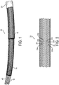
- Fig. 1 is a drawing depicting a perspective view of an exemplary hose assembly 10 in accordance with embodiments of the present invention.
- the hose assembly includes an inner hose component 12, a first or inner braid 14 of reinforcement fiber, and a second braid 16 of reinforcement fiber that is located outwardly in the hose assembly relative to the first braid 14.
- “Inner” versus “outer” in this context refers to the positioning of pertinent components relative to the space defined by the hose component in which the fluid flows, with the inner hose component being the innermost component.
- the first braid 14 extends around the inner hose component 12, and the second braid 16 extends around the first braid 14.
- Hose or “hose component” may refer to any generally tubular, elongated member or device and includes flexible, semi-flexible and rigid devices commonly referred to as “hoses,” “tubes,” “pipes” and the like. Hoses may have different cross-sections, and may have for example, round, oval, polygonal or other cross sectional shapes. Hoses may be of any material, including, for example, thermosetting, thermoplastic, metallic and non-metallic materials. Hoses may be single wall, multiple wall, reinforced or non-reinforced, and may include end fittings or no end fittings.
- common hose materials may include various rigid or semi-rigid materials that resist corrosion and have the strength capacity for the high pressures and flow rates associated with undersea applications.
- Example hose materials may include various polyamide materials with ranging amounts of plasticizers as are known in the art.
- the first braid 14 and the second braid 16 may have a "3 over 3" braid design of reinforcement fiber, with the first braid 14 covering an outer surface of and extending around the inner hose component 12, and the second braid 16 covering an outer surface of and extending around the first braid 14.
- Fig. 2 is a drawing depicting an exemplary 3 over 3 braid configuration 20 that generally may be employed in the first and second braids of the present invention.
- the term "3 over 3" refers to the pattern of weave of the fiber bundles that form the braid. Referring to Fig.
- a first fiber bundle 22 may include three adjacent fiber strands 22a, 22b, and 22c.
- a second fiber bundle 24 also may include three adjacent fiber strands 24a, 24b, and 24c.
- the three-fibered fibers bundles 22 and 24 are then weaved together in a patterned braid fashion to form the 3 over 3 braid configuration shown in Fig. 2 .
- an “aspect ratio” is a term that denotes a ratio of the wavelength (undulation length) of braid segments relative to the amplitude of the braid segments.
- the "wavelength” is defined as a distance along the braid path of one complete undulation, which equals the helix length of one carrier for one complete pitch over the complete undulations per helix length in one pitch.
- the "amplitude” is defined as the maximum radial difference of reinforcement for the undulation pattern, which equals the outermost braid radius minus the inner most braid radius.
- the wavelength, and thus the resultant aspect ratio differs in a conventional 2 over 2 braid design.
- the aspect ratio for the 3 over 3 braid design is 50% more than that of a 2 over 2 braid design generated under comparable circumstances.
- a larger aspect ratio is advantageous for reducing cross over points where stress accumulates, which must be balanced against the need for sufficient braid material for adequate reinforcement insofar as a higher aspect ratio generally may be achieved by reducing the braid thickness (i.e., a thinner braid may have a higher aspect ratio).
- the enhanced 3 over 3 braid design of the present invention reduces the number of fiber cross-over points, or in other words increases the aspect ratio of cross overs, substantially as compared to conventional 2 over 2 braid configurations as demonstrated by the above calculations.
- burst pressure refers to the maximum pressure achievable without hose assembly failure
- impulse life refers to cyclic pressure fatigue under the conditions of exposure.
- the referenced aspect ratio enhancement reduces fibers stress and yields increased burst pressure resistance of about 3-7% over exemplary configurations.
- the aspect ratio achieved by the 3 over 3 braid configuration of the present invention may be at least six, and preferably within a range of about 6.6 to 7.5, which is suitable for hose reinforcement in undersea drilling operations and other high pressure applications.
- each of the first braid 14 and second braid 16 individually may have the 3 over 3 braid configuration, and the two braids are layered on the inner hose component 12.
- the braids may be made of an aramid (aromatic polyamide) fiber material, and a para-aramid fiber material in a preferred embodiment.
- Aramid and para-aramid materials generally are corrosion resistant and high strength synthetic fiber materials. Examples of suitable aramid or para-aramid materials include Kevlar and Twaron.
- the first braid may have a first modulus and the second braid may have a second modulus that is different from the first modulus.
- the two braid layers may include in combination a high strength first inner braid 14 and a high modulus second braid 16 outward relative to the high strength first braid.
- the first braid 14 can be referred to as a high strength braid having a strength greater than a strength of the second braid 16.
- the second braid 16 may be referred to as a high modulus braid having a modulus greater than a modulus of the first braid 14.
- the second braid 16 may permit overall elongation to increase efficiency by having a higher modulus relative to the first braid 14.
- the braids are configured with such different modulus to work in tandem to optimize load sharing across the hose assembly 10. This is accomplished by utilizing the referenced aramid or para-aramid fibers optimized for high strength on the high strength first braid .
- the high modulus second braid utilizes a high modulus fiber that also may be aramid or para-aramid, otherwise selected so that the braid will absorb and take up a greater level of stress and better support the first braid.
- the braid layers may be modified relative to each other to enhance or optimize performance for particular conditions.
- the second braid layer 16 may be thinner than the first braid layer 14 so that second braid layer can have a greater aspect ratio than the aspect ratio of the first braid layer.
- the aspect ratio may be 6.6 to 7.5
- the higher aspect ratio of the second braid layer may be in the range of approximately 12 to 15.
- the aspect ratio of the second braid is at least 30% higher than the aspect ratio of the first braid. Having a thinner, higher aspect ratio second braid layer improves engagement of the two braid layers, which enhances the overall modulus of the assembly.
- the hose assembly 10 further may include an outer sheath layer 25 that extends around the second braid 16.
- the outer sheath layer may be made of any suitable elastomeric material, which may be reinforced, that acts as an outer protective covering for the hose assembly 10.
- Fig. 1 employs a design with two braid layers.
- a layered design of three braids may be utilized for enhanced reinforcement.
- the benefit of the third braid for enhanced reinforcement generally may be balanced against negatives of adding the third braid.
- a third braid may add cost, weight, and unwanted stiffness to the hose assembly. In the configuration of the present invention, therefore, the third braid layer often may not be present, but constitutes an option for applications in which even more enhanced reinforcement is desirable.
- a third braid layer may be added to the outer surface of the second braid layer 16, and the sheath 25 then covers the third braid layer.
- Fig. 3 is a drawing depicting a perspective view of the exemplary hose assembly 10 modified to have three braid layers in accordance with embodiments of the present invention, with the outer sheath 25 removed for convenient illustration.
- Fig. 3 shows a third braid layer 26 is added to the outer surface of the second braid layer 16, and thus the third braid extends around the second braid.
- the third braid layer 26 also is therefore located in the hose assembly 10 between the second braid layer 16 and the outer sheath, and thus the outer sheath extends around the third braid in a three-braid embodiment.
- the third braid 26 may have properties in common with the first braid 14 and the second braid 16.
- the third braid also may have a 3 over 3 braid design, and/or may be made of an aramid or para-aramid fiber material such as Kevlar or Twaron.
- the third braid layer 26 may be a high angle braid.
- a "high angle braid” as a braid in which the braid segments are oriented at an angle of at least 54.7 degrees relative to a neutral line corresponding to a longitudinal axis of the hose assembly in a direction of fluid flow.
- the high angle third braid segments may be applied at an angle of at least 55 degrees, and preferably 57 to 60 degrees, relative to the neutral line or longitudinal axis of the hose assembly.
- the high angle third braid may minimally add to impulse life, and has a principal purpose of providing increased burst pressure support when the first and second braids are highly loaded.
- the high angle nature of the third braid thus enhances the overall burst pressure resistance of the assembly, and a high modulus aramid or para-aramid fiber also may be used for the third braid to maximize loading capacity, with for example an EOB comparable to the second braid or about 2.5%.
- hose assembly fitting may be combined with an enhanced hose assembly fitting for connecting the hose assembly to suitable fluid system equipment.
- the hose assembly configuration of the present invention may work together with the fitting to enhance both burst pressure resistance and impulse life of the hose assembly, while maintaining effective engagement with fluid system equipment under high pressures and flow rates.
- a hose assembly fitting include an outer shell that is connected to a nipple that is located radially inward relative to the outer shell.
- the outer shell and the nipple define a groove spacing for receiving the hose assembly, and the outer shell is crimped toward the nipple to secure the hose assembly within the groove spacing.
- An inner surface of the outer shell includes blunt groove features that define the groove spacing, and a hose receiving end of the nipple is a threaded end including a plurality of threads.
- Fig. 4 is a schematic diagram depicting an exemplary hose fitting 30 in accordance with embodiments of the present invention.
- the hose fitting 30 includes an outer shell 32 that is connected to a nipple 34, the nipple 34 being located radially inward relative to the outer shell.
- the outer shell 32 may be threaded onto the nipple 34.
- the outer shell 32 and nipple 34 define a groove spacing 36 for receiving the hose assembly 10.
- the relative wide groove spacing 36 permits the hose assembly to move into the grooves and not push out of the fitting, which can distort the braiding.
- the outer shell may be crimped onto the hose assembly, such as by using a hydraulic press.
- the shell/nipple design is optimized for 8-die crimped fittings as are known in the art.
- the nipple 34 further may include a first fixing end 33 that is fixed to a fluid connector 35 that may be configured as a bookend joint.
- the fluid connector or bookend joint 35 permits connection of the hose assembly fitting to porting on fluid system equipment.
- the outer shell 32 may be made of a low yield strength stainless steel and may be annealed. This prevents spring back of the outer shell when crimped.
- the outer shell may include a tapered skirt 38 at an end of the outer shell opposite from an end 39 where the outer shell is threaded onto or otherwise connected to the nipple.
- the tapered skirt 38 particularly prevents early yarn fractures during burst and impulse testing.
- An inner surface of the outer shell includes blunt groove features 37 that define the groove spacing 36.
- the blunt nature of groove features 37 permits the outer sheath material to readily slide along the groove features without the hose assembly pushing out from the fitting.
- the blunt groove features 37 are less aggressive than conventional barbs, and thus have less of a tendency to cut into the outer sheath material thereby preventing water ingress into the hose assembly.
- the nipple 34 may be made of a suitable high strength material as are known in the art, such as a high strength metal material.
- a yield pressure for failure of the nipple may be greater than the burst pressure of the hose assembly, and preferably approximately 120% of the burst pressure of the hose assembly.
- a hose receiving end 40 of the nipple may extend from a nipple body 44.
- the nipple body 44 may have an external grooved surface 46. The grooved surface 46 allows for improved sealing, with the inner surface of the inner hose of the hose assembly.
- the hose assembly 10 and the hose assembly fitting 30 may be joined to form a hose system.
- the hose receiving end 40 of the nipple 34 is configured as a threaded end including a plurality of threads 42.
- the inner hose component 12 of the hose assembly 10 is configured as a carcass having a plurality of pitched grooves that interact with the threads of the hose receiving end of the nipple to secure the hose assembly 10 to the hose assembly fitting 30.
- An example of such pitched grooves is identified as element 43 in Fig. 1 .
- a characteristic of the hose carcass is that when twisted clockwise (if looking at the carcass end), the carcass essentially swells and the pitch of the grooves lengthens. Conversely, if twisted in a counter-clockwise direction, the carcass necks down and the pitch of the grooves shortens.
- the threads 42 of the nipple of the hose assembly fitting are designed to have a longer pitch than a pitch of the pitched grooves of the inner hose component carcass.
- the pitch of the nipple threads 42 is slightly longer than the carcass, there is a binding action between the carcass and nipple.
- the carcass wants to neck down and the pitch shorten, but this cannot occur due to the threads 42, which strongly secures the nipple 34 within the hose assembly 10.
- only three threads 42 may be needed for full engagement of the nipple and hose assembly to prevent separation of the nipple and hose assembly, although different numbers of threads may be employed as appropriate for any suitable application.
- An aspect of the invention is a hose assembly having an enhanced braided layer design.
- the hose assembly includes an inner hose component, a first braid of reinforcement fiber material that extends around the inner hose component, and a second braid of reinforcement fiber material that extends around the first braid.
- the first braid and the second braid each has a 3 over 3 braid design, and the first braid has a first modulus and the second braid has a second modulus that is different from the first modulus.
- An aspect ratio of the first braid and the second braid comprises a ratio of a wavelength of braid segments to an amplitude of braid segments, and the aspect ratio of the second braid is greater than the aspect ratio of the first braid.
- the aspect ratio of the first braid and the second braid is at least six.
- the aspect ratio of the second braid is at least 30% higher than the aspect ratio of the first braid.
- the first braid may be a high strength braid having a strength greater than a strength of the second braid.
- the second braid may be a high modulus braid having a modulus greater than a modulus of the first braid.
- the first braid and the second braid are made of an aramid fiber material or a para-aramid fiber material.
- the first braid and the second braid are made of para-aramid fiber.
- the hose assembly further includes a third braid of reinforcement fiber material that extends around the second braid, wherein the third braid has a 3 over 3 braid design.
- the third braid has a high angle configuration in which braid segments are oriented an angle of at least 55 degrees relative to a neutral line corresponding to a longitudinal axis of the hose assembly.
- the angle of the high angle configuration is 57 to 60 degrees.
- the third braid is made of an aramid fiber material or a para-aramid fiber material.
- the third braid is made of a para-aramid fiber.
- the hose assembly further includes an outer sheath that extends around the second braid.
- the hose assembly further includes an outer sheath that extends around the third braid.
- a hose assembly fitting for connecting a hose assembly to fluid system equipment is also disclosed.
- the hose assembly fitting includes an outer shell that is connected to a nipple that is located radially inward relative to the outer shell, the outer shell and the nipple defining a groove spacing for receiving the hose assembly, and the outer shell is crimped toward the nipple to secure the hose assembly within the groove spacing.
- An inner surface of the outer shell includes blunt groove features that define the groove spacing.
- a hose receiving end of the nipple is a threaded end including a plurality of threads.
- the hose assembly fitting may include one or more of the following features, either individually or in combination.
- the outer shell includes a tapered skirt at an end of the nipple opposite from an end where the outer shell is connected to the nipple.
- the hose assembly fitting further includes a fluid connector for connecting the hose assembly fitting to fluid system equipment, wherein the nipple includes a fixing end for fixing the nipple to the fluid connector.
- hose system including the hose assembly according to any of the embodiments, and the hose assembly fitting according to any of the examples.
- the inner hose component of the hose assembly is configured as a carcass having a plurality of pitched grooves that interact with the threads of the hose receiving end of the nipple to secure the hose assembly to the hose assembly fitting.
- the threads of the hose assembly fitting have a longer pitch than a pitch of the pitched grooves of the inner hose component of the hose assembly.
Landscapes
- Engineering & Computer Science (AREA)
- General Engineering & Computer Science (AREA)
- Mechanical Engineering (AREA)
- Rigid Pipes And Flexible Pipes (AREA)
- Supports For Pipes And Cables (AREA)
Description
- The present invention relates generally to hose configurations suitable for use in environments in which hoses may be subject to high pressures, such as for example in deep subsea applications or comparable.
- Hydraulic and other hoses may be subjected to substantial pressures in certain environments of use. In one particular exemplary application, hydraulic and other hoses may be employed in deep undersea oil and gas drilling operations, including in blow-off preventers that act as a safety feature that closes off a drilling operation in case of a catastrophic failure. Other undersea hose applications may include hydraulic hoses, flying leads, hotline hoses, and hoses used with subsea umbilicals.
- Hoses in undersea oil and gas drilling operations may experience enormous high external pressures, sometimes at 5000 psi and above, where 1 psi is about 0.07 bars (i.e. 1000 psi is about 70 bars), and often at pressures of 8000-9000 psi. At such pressures, there is a danger of hose failure if the hose is not designed to accommodate such pressure levels. Accordingly, hoses need to be collapse resistant when subjected to such pressures, and also must be highly impulse fatigue resistant to accommodate the impulse pressures of the fluids being transported through the hoses with high flow rates.
- US Patent Publication no.
US-2011/0036442A1 discloses a hose assembly which includes a core tube having an outer peripheral surface and which is formed from a fluoropolymer. The hose assembly also includes a first reinforcing layer disposed about the core tube and defining a plurality of first apertures, and a second reinforcing layer disposed about the first reinforcing layer and having an exterior surface and defining a plurality of second apertures. The hose assembly further includes a polymeric binder, formed from a binder composition, on the outer peripheral surface of the core tube, in the first and second apertures, and about the exterior surface of the second reinforcing layer to bond the first and second reinforcing layers to the core tube. - The present invention is an enhanced hose assembly configuration that provides a higher performance hose product as compared to conventional configurations, while still using readily available materials and manufacturing technology. In this manner, a hose assembly is configured to be both sufficiently collapse resistant and impulse pressure resistant for use particularly in undersea applications and other applications in which hose assemblies may be subjected to high pressures and flow rates. Generally, a high pressure hose assembly with maximized impulse life is achieved by a hose assembly design that minimizes stress on the hose reinforcement fiber layers, which can then be used in combination with a fitting that minimizes disruption and stresses at the attachment point of the hose assembly and fitting. The hose assembly configuration of the present invention thus may work together with a suitable fitting to enhance both burst pressure resistance and impulse life of the hose assembly.
- The hose assembly includes a "3 over 3" braid design of reinforcement fibers, which may be fixed to an outer surface of an inner hose component. Recent advancements in braider machine designs have yielded the capability to form an effective 3 over 3 braid design versus a traditional 2 over 2 braid design that is typical of conventional configurations. The enhanced 3 over 3 braid design reduces the number of fiber cross-over points, and increases the aspect ratio (wavelength over amplitude in the braid) of cross overs substantially over conventional configurations. This enhanced aspect ratio reduces fiber stress and yields increased burst of about 3-7%.
- The hose assembly further includes a two-braid design in which two layers of 3 over 3 braiding are provided, with each braid layer having a different modulus. The two braid layers may include in combination a high strength first braid (which may be an inner most braid layer) and a high modulus second braid which may be outward relative to the high strength first braid. To increase burst strength resistance and impulse life, the braids are configured with each braid layer having a different modulus so as to work in tandem to optimize load sharing across the hose assembly. This may be accomplished by utilizing aramid fibers optimized for high strength on the high strength first braid. Such aramid fibers have a maximum break strength and also have relative high stretch (e.g., "elongation at break", EOB=3.3%) as compared to the high modulus second braid. This higher stretch characteristic of the high strength first braid allows the first braid to better engage the high modulus second braid. The high modulus second braid utilizes a high modulus fiber selected so that the braid will absorb and take up a greater level of stress and better support the first braid. The high modulus fiber does not stretch much at break (e.g., EOB= 2.5%). This difference in stretch allows the braids to work in tandem to better share impulse load and achieve longer impulse life at higher pressures.
- The hose assembly described above may be combined with an enhanced fitting for connecting the hose assembly to suitable fluid system equipment. As referenced above, the hose assembly configuration of the present invention may work together with the fitting to enhance both burst pressure resistance and impulse life of the hose assembly while providing an effective connection to fluid system equipment in environments of high pressures and flow rates, such as for example may be experienced in undersea drilling operations.
- In exemplary embodiments, the hose assembly optionally may include an additional high angle third braid located in the assembly outwardly relative to the second braid. In particular, the high angle third braid may be applied with the braid segments being oriented at an angle of at least 55 degrees relative to a neutral line or longitudinal axis of the hose assembly. The high angle third braid may minimally add to impulse life, and has a principal purpose of providing increased burst pressure support when the first and second braids are highly loaded. The high angle nature of the third braid enhances the burst pressure resistance, and a high modulus fiber also may be used for the third braid to maximize loading capacity, with for example an EOB comparable to the second braid or about 2.5%.
- An aspect of the invention, therefore, is a hose assembly as claimed in claim 1. The hose assembly includes an inner hose component, a first braid of reinforcement fiber material that extends around the inner hose component, and a second braid of reinforcement fiber material that extends around the first braid. The first braid and the second braid each has a 3 over 3 braid design, and the first braid has a first modulus and the second braid has a second modulus that is different from the first modulus. The first braid may be a high strength braid having a strength greater than a strength of the second braid, and the second braid may be a high modulus braid having a modulus greater than a modulus of the first braid. The hose assembly optionally may have a third braid with a high angle configuration of the braid segments. The braid layers may be made of an aramid or para-aramid fiber material. The hose assembly may be combined with an enhanced fitting for securing the hose assembly to fluid system equipment.
- Optional further features of the hose assembly are defined in the dependent claims.
- These and further features of the present invention will be apparent with reference to the following description and attached drawings. In the description and drawings, particular embodiments of the invention have been disclosed in detail as being indicative of some of the ways in which the principles of the invention may be employed, but it is understood that the invention is not limited correspondingly in scope. Rather, the invention includes all changes, modifications and equivalents coming within the terms of the claims appended hereto. Features that are described and/or illustrated with respect to one embodiment may be used in the same way or in a similar way in one or more other embodiments and/or in combination with or instead of the features of the other embodiments.
-
-
Fig. 1 is a drawing depicting a perspective view of an exemplary hose assembly with two braid layers in accordance with embodiments of the present invention. -
Fig. 2 is a drawing depicting an exemplary 3 over 3 braid configuration. -
Fig. 3 is a drawing depicting a perspective view of an exemplary hose assembly with three braid layers in accordance with embodiments of the present invention. -
Fig. 4 is a schematic diagram depicting an exemplary hose fitting in accordance with embodiments of the present invention. - Embodiments of the present invention will now be described with reference to the drawings, wherein like reference numerals are used to refer to like elements throughout. It will be understood that the figures are not necessarily to scale.
- The present invention is a hose assembly that has enhanced burst pressure resistance and impulse life for high pressure applications, such as undersea oil and gas drilling applications, as compared to conventional configurations. Generally, in exemplary embodiments, the hose assembly may include an inner hose component, a first braid of reinforcement fiber material that extends around the inner hose component, and a second braid of reinforcement fiber material that extends around the first braid. The first braid and the second braid each have a 3 over 3 braid design, and the first braid has a first modulus and the second braid a second modulus that is different from the first modulus.
-
Fig. 1 is a drawing depicting a perspective view of anexemplary hose assembly 10 in accordance with embodiments of the present invention. As shown in the example ofFig. 1 , the hose assembly includes aninner hose component 12, a first orinner braid 14 of reinforcement fiber, and asecond braid 16 of reinforcement fiber that is located outwardly in the hose assembly relative to thefirst braid 14. "Inner" versus "outer" in this context refers to the positioning of pertinent components relative to the space defined by the hose component in which the fluid flows, with the inner hose component being the innermost component. Accordingly, thefirst braid 14 extends around theinner hose component 12, and thesecond braid 16 extends around thefirst braid 14. - It will be appreciated that the specific inner hose component depicted in
Fig. 1 is a non-limiting example. The term "hose" or "hose component" may refer to any generally tubular, elongated member or device and includes flexible, semi-flexible and rigid devices commonly referred to as "hoses," "tubes," "pipes" and the like. Hoses may have different cross-sections, and may have for example, round, oval, polygonal or other cross sectional shapes. Hoses may be of any material, including, for example, thermosetting, thermoplastic, metallic and non-metallic materials. Hoses may be single wall, multiple wall, reinforced or non-reinforced, and may include end fittings or no end fittings. In undersea hydraulic applications, common hose materials may include various rigid or semi-rigid materials that resist corrosion and have the strength capacity for the high pressures and flow rates associated with undersea applications. Example hose materials may include various polyamide materials with ranging amounts of plasticizers as are known in the art. - In exemplary embodiments, the
first braid 14 and thesecond braid 16 may have a "3 over 3" braid design of reinforcement fiber, with thefirst braid 14 covering an outer surface of and extending around theinner hose component 12, and thesecond braid 16 covering an outer surface of and extending around thefirst braid 14. As referenced above, recent advancements in braider machine designs have yielded the capability to form an effective 3 over 3 braid design versus a traditional 2 over 2 braid design that is typical of conventional configurations.Fig. 2 is a drawing depicting an exemplary 3 over 3braid configuration 20 that generally may be employed in the first and second braids of the present invention. The term "3 over 3" refers to the pattern of weave of the fiber bundles that form the braid. Referring toFig. 2 , afirst fiber bundle 22 may include threeadjacent fiber strands second fiber bundle 24 also may include threeadjacent fiber strands Fig. 2 . - As defined in the context of the current invention, an "aspect ratio" is a term that denotes a ratio of the wavelength (undulation length) of braid segments relative to the amplitude of the braid segments. As used in connection with braided designs, the "wavelength" is defined as a distance along the braid path of one complete undulation, which equals the helix length of one carrier for one complete pitch over the complete undulations per helix length in one pitch. The "amplitude" is defined as the maximum radial difference of reinforcement for the undulation pattern, which equals the outermost braid radius minus the inner most braid radius.
- As a typical numerical example, for a 24 carrier braider with helix length of 36 mm and a 3 over 3 braid pattern, the wavelength equals 36 / 4 = 9. A typical example for amplitude is an innermost braided layer with braid outside diameter of 18 mm and inner tube outside diameter of 12 mm. Amplitude for such example is calculated as (18 / 2) - (12 / 2) = 9 - 6 = 3. The aspect ratio for the 3 over 3 braid pattern is then the ratio of wavelength / amplitude = 9/3 = 3. By comparison, the wavelength, and thus the resultant aspect ratio, differs in a conventional 2 over 2 braid design. In a comparable numerical example for the same 24 carrier braider with helix length of 36 mm, the wavelength for a 2 over 2 braid pattern = 36 / 6 = 6. With the amplitude calculation yielding a comparable result of 3, the aspect ratio for the 2 over 2 braid pattern is wavelength / amplitude = 6/3 = 2. As shown by this example, therefore, the aspect ratio for the 3 over 3 braid design is 50% more than that of a 2 over 2 braid design generated under comparable circumstances.
- For reinforcement applications, a larger aspect ratio is advantageous for reducing cross over points where stress accumulates, which must be balanced against the need for sufficient braid material for adequate reinforcement insofar as a higher aspect ratio generally may be achieved by reducing the braid thickness (i.e., a thinner braid may have a higher aspect ratio). The enhanced 3 over 3 braid design of the present invention reduces the number of fiber cross-over points, or in other words increases the aspect ratio of cross overs, substantially as compared to conventional 2 over 2 braid configurations as demonstrated by the above calculations. In measuring hose assembly performance, burst pressure refers to the maximum pressure achievable without hose assembly failure, and impulse life refers to cyclic pressure fatigue under the conditions of exposure. The referenced aspect ratio enhancement reduces fibers stress and yields increased burst pressure resistance of about 3-7% over exemplary configurations. In exemplary embodiments, the aspect ratio achieved by the 3 over 3 braid configuration of the present invention may be at least six, and preferably within a range of about 6.6 to 7.5, which is suitable for hose reinforcement in undersea drilling operations and other high pressure applications.
- Referring again to
Fig. 1 , in exemplary embodiments each of thefirst braid 14 andsecond braid 16 individually may have the 3 over 3 braid configuration, and the two braids are layered on theinner hose component 12. The braids may be made of an aramid (aromatic polyamide) fiber material, and a para-aramid fiber material in a preferred embodiment. Aramid and para-aramid materials generally are corrosion resistant and high strength synthetic fiber materials. Examples of suitable aramid or para-aramid materials include Kevlar and Twaron. - In exemplary embodiments, the first braid may have a first modulus and the second braid may have a second modulus that is different from the first modulus. The two braid layers may include in combination a high strength first
inner braid 14 and a high modulussecond braid 16 outward relative to the high strength first braid. In other words, thefirst braid 14 can be referred to as a high strength braid having a strength greater than a strength of thesecond braid 16. In addition, thesecond braid 16 may be referred to as a high modulus braid having a modulus greater than a modulus of thefirst braid 14. - In this manner, the
second braid 16 may permit overall elongation to increase efficiency by having a higher modulus relative to thefirst braid 14. To increase burst pressure resistance and impulse life, the braids are configured with such different modulus to work in tandem to optimize load sharing across thehose assembly 10. This is accomplished by utilizing the referenced aramid or para-aramid fibers optimized for high strength on the high strength first braid . Such aramid fibers have a maximum break strength and also has relative high stretch (e.g., EOB=3.3%) as compared to the high modulus second braid. This higher stretch characteristic of the high strength first braid allows the first braid to better engage the high modulus second braid. The high modulus second braid utilizes a high modulus fiber that also may be aramid or para-aramid, otherwise selected so that the braid will absorb and take up a greater level of stress and better support the first braid. The high modulus fiber does not stretch much at break (e.g., EOB= 2.5%). This difference in stretch allows the braids to work in tandem to better share impulse load and achieve longer impulse life at higher pressures. - Configured as above, with high aspect ratio aramid or para-aramid braids, test pressures of about 26,000-31,000 psi have been achieved using a single braid layer. With the addition of the second braid layer, test pressures up to about 45,000 psi have been achieved. The braid layers may be modified relative to each other to enhance or optimize performance for particular conditions. For example, the
second braid layer 16 may be thinner than thefirst braid layer 14 so that second braid layer can have a greater aspect ratio than the aspect ratio of the first braid layer. In exemplary embodiments, as referenced above the aspect ratio may be 6.6 to 7.5, and the higher aspect ratio of the second braid layer may be in the range of approximately 12 to 15. The aspect ratio of the second braid is at least 30% higher than the aspect ratio of the first braid. Having a thinner, higher aspect ratio second braid layer improves engagement of the two braid layers, which enhances the overall modulus of the assembly. - The
hose assembly 10 further may include anouter sheath layer 25 that extends around thesecond braid 16. The outer sheath layer may be made of any suitable elastomeric material, which may be reinforced, that acts as an outer protective covering for thehose assembly 10. - The embodiment of
Fig. 1 employs a design with two braid layers. In certain applications, a layered design of three braids may be utilized for enhanced reinforcement. The benefit of the third braid for enhanced reinforcement generally may be balanced against negatives of adding the third braid. A third braid may add cost, weight, and unwanted stiffness to the hose assembly. In the configuration of the present invention, therefore, the third braid layer often may not be present, but constitutes an option for applications in which even more enhanced reinforcement is desirable. - In applications where benefits of a third braid outweigh the drawbacks, a third braid layer may be added to the outer surface of the
second braid layer 16, and thesheath 25 then covers the third braid layer.Fig. 3 is a drawing depicting a perspective view of theexemplary hose assembly 10 modified to have three braid layers in accordance with embodiments of the present invention, with theouter sheath 25 removed for convenient illustration. - In particular,
Fig. 3 shows athird braid layer 26 is added to the outer surface of thesecond braid layer 16, and thus the third braid extends around the second braid. Thethird braid layer 26 also is therefore located in thehose assembly 10 between thesecond braid layer 16 and the outer sheath, and thus the outer sheath extends around the third braid in a three-braid embodiment. Thethird braid 26 may have properties in common with thefirst braid 14 and thesecond braid 16. For example, the third braid also may have a 3 over 3 braid design, and/or may be made of an aramid or para-aramid fiber material such as Kevlar or Twaron. - In exemplary embodiments, the
third braid layer 26 may be a high angle braid. In the braiding art particularly as associated with hose assembly reinforcement braids, those of ordinary skill in art define a "high angle braid" as a braid in which the braid segments are oriented at an angle of at least 54.7 degrees relative to a neutral line corresponding to a longitudinal axis of the hose assembly in a direction of fluid flow. In embodiments of the present invention, the high angle third braid segments may be applied at an angle of at least 55 degrees, and preferably 57 to 60 degrees, relative to the neutral line or longitudinal axis of the hose assembly. The high angle third braid may minimally add to impulse life, and has a principal purpose of providing increased burst pressure support when the first and second braids are highly loaded. The high angle nature of the third braid thus enhances the overall burst pressure resistance of the assembly, and a high modulus aramid or para-aramid fiber also may be used for the third braid to maximize loading capacity, with for example an EOB comparable to the second braid or about 2.5%. - The hose assembly described above may be combined with an enhanced hose assembly fitting for connecting the hose assembly to suitable fluid system equipment. As referenced above, the hose assembly configuration of the present invention may work together with the fitting to enhance both burst pressure resistance and impulse life of the hose assembly, while maintaining effective engagement with fluid system equipment under high pressures and flow rates. Generally, embodiments of a hose assembly fitting include an outer shell that is connected to a nipple that is located radially inward relative to the outer shell. The outer shell and the nipple define a groove spacing for receiving the hose assembly, and the outer shell is crimped toward the nipple to secure the hose assembly within the groove spacing. An inner surface of the outer shell includes blunt groove features that define the groove spacing, and a hose receiving end of the nipple is a threaded end including a plurality of threads.
-
Fig. 4 is a schematic diagram depicting an exemplary hose fitting 30 in accordance with embodiments of the present invention. The hose fitting 30 includes anouter shell 32 that is connected to anipple 34, thenipple 34 being located radially inward relative to the outer shell. For example, theouter shell 32 may be threaded onto thenipple 34. - The
outer shell 32 andnipple 34 define agroove spacing 36 for receiving thehose assembly 10. The relative wide groove spacing 36 permits the hose assembly to move into the grooves and not push out of the fitting, which can distort the braiding. Once the hose assembly is inserted into thegroove spacing 36, the outer shell may be crimped onto the hose assembly, such as by using a hydraulic press. The shell/nipple design is optimized for 8-die crimped fittings as are known in the art. Thenipple 34 further may include a first fixing end 33 that is fixed to afluid connector 35 that may be configured as a bookend joint. The fluid connector or bookend joint 35 permits connection of the hose assembly fitting to porting on fluid system equipment. - The
outer shell 32 may be made of a low yield strength stainless steel and may be annealed. This prevents spring back of the outer shell when crimped. The outer shell may include a taperedskirt 38 at an end of the outer shell opposite from anend 39 where the outer shell is threaded onto or otherwise connected to the nipple. The taperedskirt 38 particularly prevents early yarn fractures during burst and impulse testing. An inner surface of the outer shell includes blunt groove features 37 that define thegroove spacing 36. The blunt nature of groove features 37 permits the outer sheath material to readily slide along the groove features without the hose assembly pushing out from the fitting. The blunt groove features 37 are less aggressive than conventional barbs, and thus have less of a tendency to cut into the outer sheath material thereby preventing water ingress into the hose assembly. - The
nipple 34 may be made of a suitable high strength material as are known in the art, such as a high strength metal material. In exemplary embodiments, a yield pressure for failure of the nipple may be greater than the burst pressure of the hose assembly, and preferably approximately 120% of the burst pressure of the hose assembly. Ahose receiving end 40 of the nipple may extend from anipple body 44. Thenipple body 44 may have an externalgrooved surface 46. Thegrooved surface 46 allows for improved sealing, with the inner surface of the inner hose of the hose assembly. - The
hose assembly 10 and the hose assembly fitting 30 may be joined to form a hose system. To enhance the secured fit of the hose assembly and the hose assembly fitting, thehose receiving end 40 of thenipple 34 is configured as a threaded end including a plurality ofthreads 42. In addition, theinner hose component 12 of thehose assembly 10 is configured as a carcass having a plurality of pitched grooves that interact with the threads of the hose receiving end of the nipple to secure thehose assembly 10 to the hose assembly fitting 30. An example of such pitched grooves is identified aselement 43 inFig. 1 . - A characteristic of the hose carcass is that when twisted clockwise (if looking at the carcass end), the carcass essentially swells and the pitch of the grooves lengthens. Conversely, if twisted in a counter-clockwise direction, the carcass necks down and the pitch of the grooves shortens. The
threads 42 of the nipple of the hose assembly fitting are designed to have a longer pitch than a pitch of the pitched grooves of the inner hose component carcass. When threading the nipple into the hose assembly carcass (right-hand thread), the carcass swells and the pitch elongates allowing the nipple to be threaded into in the inner hose. Since the pitch of thenipple threads 42 is slightly longer than the carcass, there is a binding action between the carcass and nipple. When a force to unscrew the nipple is applied in a counter-clock wise direction, the carcass wants to neck down and the pitch shorten, but this cannot occur due to thethreads 42, which strongly secures thenipple 34 within thehose assembly 10. In exemplary embodiments, only threethreads 42 may be needed for full engagement of the nipple and hose assembly to prevent separation of the nipple and hose assembly, although different numbers of threads may be employed as appropriate for any suitable application. - An aspect of the invention, therefore, is a hose assembly having an enhanced braided layer design. The hose assembly includes an inner hose component, a first braid of reinforcement fiber material that extends around the inner hose component, and a second braid of reinforcement fiber material that extends around the first braid. The first braid and the second braid each has a 3 over 3 braid design, and the first braid has a first modulus and the second braid has a second modulus that is different from the first modulus.
- An aspect ratio of the first braid and the second braid comprises a ratio of a wavelength of braid segments to an amplitude of braid segments, and the aspect ratio of the second braid is greater than the aspect ratio of the first braid.
- In an exemplary embodiment of the hose assembly, the aspect ratio of the first braid and the second braid is at least six.
- The aspect ratio of the second braid is at least 30% higher than the aspect ratio of the first braid.
- The first braid may be a high strength braid having a strength greater than a strength of the second braid.
- The second braid may be a high modulus braid having a modulus greater than a modulus of the first braid.
- In an exemplary embodiment of the hose assembly, the first braid and the second braid are made of an aramid fiber material or a para-aramid fiber material.
- In an exemplary embodiment of the hose assembly, the first braid and the second braid are made of para-aramid fiber.
- In an exemplary embodiment of the hose assembly, the hose assembly further includes a third braid of reinforcement fiber material that extends around the second braid, wherein the third braid has a 3 over 3 braid design.
- In an exemplary embodiment of the hose assembly, the third braid has a high angle configuration in which braid segments are oriented an angle of at least 55 degrees relative to a neutral line corresponding to a longitudinal axis of the hose assembly.
- In an exemplary embodiment of the hose assembly, the angle of the high angle configuration is 57 to 60 degrees.
- In an exemplary embodiment of the hose assembly, the third braid is made of an aramid fiber material or a para-aramid fiber material.
- In an exemplary embodiment of the hose assembly, the third braid is made of a para-aramid fiber.
- In an exemplary embodiment of the hose assembly, the hose assembly further includes an outer sheath that extends around the second braid.
- In an exemplary embodiment of the hose assembly, the hose assembly further includes an outer sheath that extends around the third braid.
- A hose assembly fitting for connecting a hose assembly to fluid system equipment is also disclosed. In exemplary hose assembly fittings, the hose assembly fitting includes an outer shell that is connected to a nipple that is located radially inward relative to the outer shell, the outer shell and the nipple defining a groove spacing for receiving the hose assembly, and the outer shell is crimped toward the nipple to secure the hose assembly within the groove spacing. An inner surface of the outer shell includes blunt groove features that define the groove spacing. A hose receiving end of the nipple is a threaded end including a plurality of threads. The hose assembly fitting may include one or more of the following features, either individually or in combination.
- In an exemplary hose assembly fitting, the outer shell includes a tapered skirt at an end of the nipple opposite from an end where the outer shell is connected to the nipple.
- In an exemplary hose assembly fitting, the hose assembly fitting further includes a fluid connector for connecting the hose assembly fitting to fluid system equipment, wherein the nipple includes a fixing end for fixing the nipple to the fluid connector.
- Another aspect of the invention is a hose system including the hose assembly according to any of the embodiments, and the hose assembly fitting according to any of the examples. In exemplary embodiments, the inner hose component of the hose assembly is configured as a carcass having a plurality of pitched grooves that interact with the threads of the hose receiving end of the nipple to secure the hose assembly to the hose assembly fitting.
- In an exemplary embodiment of the hose system, the threads of the hose assembly fitting have a longer pitch than a pitch of the pitched grooves of the inner hose component of the hose assembly.
Claims (15)
- A hose assembly (10) comprising:an inner hose component (12);a first braid (14) of reinforcement fiber material that extends around the inner hose component; anda second braid (16) of reinforcement fiber material that extends around the first braid;wherein the first braid and the second braid each has a 3 over 3 braid design;wherein the first braid has a first modulus and the second braid has a second modulus that is different from the first modulus;and wherein an aspect ratio of the first braid and the second braid comprises a ratio of a wavelength of braid segments to an amplitude of braid segments, and the aspect ratio of the second braid is at least 30% higher than the aspect ratio of the first braid.
- The hose assembly (10) of claim 1, wherein the aspect ratio of the first braid and the second braid is at least six.
- The hose assembly of either of claims 1 or 2, wherein the first braid has a strength greater than a strength of the second braid.
- The hose assembly of claim 3, wherein the second braid has a modulus greater than a modulus of the first braid.
- The hose assembly (10) of any of claims 1-4, wherein the first braid (14) and the second braid (16) are made of a para-aramid fiber material.
- The hose assembly (10) of any of claims 1-5, further comprising a third braid (26) of reinforcement fiber material that extends around the second braid (16), wherein the third braid has a 3 over 3 braid design.
- The hose assembly (10) of claim 6, wherein the third braid (26) has a high angle configuration in which braid segments are oriented an angle of at least 55 degrees relative to a neutral line corresponding to a longitudinal axis of the hose assembly.
- The hose assembly (10) of claim 7, wherein the angle of the high angle configuration is 57 to 60 degrees.
- The hose assembly (10) of any of claims 6-8, wherein the third braid (26) is made of a para-aramid fiber material.
- The hose assembly (10) of any of claims 1-9, further comprising an outer sheath (25) that extends around the second braid (16).
- The hose assembly (10) of any of claims 6-10, further comprising an outer sheath (25) that extends around the third braid (26).
- A hose system (10, 30) comprising:the hose assembly (10) according to any of claims 1-11; anda hose assembly fitting (30) for connecting the hose assembly to fluid system equipment, the hose assembly fitting comprising:an outer shell (32) that is connected to a nipple (34) that is located radially inward relative to the outer shell, the outer shell and the nipple defining a groove spacing (36) for receiving the hose assembly, and the outer shell is crimped toward the nipple to secure the hose assembly within the groove spacing;wherein an inner surface of the outer shell includes blunt groove features (37) that define the groove spacing; anda hose receiving end (40) of the nipple is a threaded end including a plurality of threads (42);wherein the inner hose component (12) of the hose assembly is configured as a carcass having a plurality of pitched grooves (43) that interact with the threads of the hose receiving end of the nipple to secure the hose assembly to the hose assembly fitting.
- The hose system (10, 30) of claim 12, wherein the threads (42) of the hose assembly fitting have a longer pitch than a pitch of the pitched groves (43) of the inner hose component (12) of the hose assembly (10).
- The hose system (10, 30) of claim 12, wherein the outer shell (32) includes a tapered skirt (38) at an end of the nipple opposite from an end where the outer shell is connected to the nipple (34).
- The hose system (10, 30) of either of claims 12 or 13, further comprising a fluid connector (35) for connecting the hose assembly fitting (30) to fluid system equipment, wherein the nipple (34) includes a fixing end (33) for fixing the nipple to the fluid connector.
Applications Claiming Priority (2)
| Application Number | Priority Date | Filing Date | Title |
|---|---|---|---|
| US201662407733P | 2016-10-13 | 2016-10-13 | |
| PCT/US2017/055820 WO2018071352A1 (en) | 2016-10-13 | 2017-10-10 | High performance aramid braided hose |
Publications (2)
| Publication Number | Publication Date |
|---|---|
| EP3526504A1 EP3526504A1 (en) | 2019-08-21 |
| EP3526504B1 true EP3526504B1 (en) | 2021-08-04 |
Family
ID=60153562
Family Applications (1)
| Application Number | Title | Priority Date | Filing Date |
|---|---|---|---|
| EP17787830.3A Active EP3526504B1 (en) | 2016-10-13 | 2017-10-10 | High performance aramid braided hose |
Country Status (4)
| Country | Link |
|---|---|
| US (1) | US11898662B2 (en) |
| EP (1) | EP3526504B1 (en) |
| BR (1) | BR112019007391B1 (en) |
| WO (1) | WO2018071352A1 (en) |
Families Citing this family (9)
| Publication number | Priority date | Publication date | Assignee | Title |
|---|---|---|---|---|
| US10690288B2 (en) | 2015-06-15 | 2020-06-23 | Other Lab, Llc | System and method for a conformable pressure vessel |
| US11000988B2 (en) | 2015-12-02 | 2021-05-11 | Other Lab, Llc | Systems and methods for liner braiding and resin application |
| WO2018081107A1 (en) * | 2016-10-24 | 2018-05-03 | Other Lab Llc | Fittings for compressed gas storage vessels |
| US20180283612A1 (en) | 2017-03-31 | 2018-10-04 | Other Lab, Llc | Tank filling system and method |
| IT201900000523A1 (en) * | 2019-01-11 | 2020-07-11 | Techinit S R L | Insert and fitting for flexible pipes, as well as a method for attaching a fitting to a flexible pipe |
| US12104718B2 (en) | 2021-02-17 | 2024-10-01 | Gamra Composites, Inc. | Fiber reinforced hoses, composite materials and articles, and related methods |
| US12145329B2 (en) | 2021-02-17 | 2024-11-19 | Gamra Composites, Inc. | Fiber reinforced composite materials, articles and related methods |
| DE102024118475B4 (en) | 2024-06-28 | 2026-03-26 | Zhejiang Tianti Rubber & Plastic Technology Co., Ltd. | High-pressure hose |
| US20260085777A1 (en) * | 2024-09-20 | 2026-03-26 | Li Chung Plastics Industry Co., Ltd. | Assembly Capable of Effectively Sealing Non-Metallic Tube Body |
Family Cites Families (25)
| Publication number | Priority date | Publication date | Assignee | Title |
|---|---|---|---|---|
| FR1372480A (en) | 1963-05-29 | 1964-09-18 | Device for electrifying fences | |
| FR1372180A (en) * | 1963-10-09 | 1964-09-11 | Aeroquip Ag | Flexible hose connection |
| US3990728A (en) | 1975-10-20 | 1976-11-09 | The Gates Rubber Company | Hose coupling |
| US4175992A (en) * | 1976-04-02 | 1979-11-27 | Caterpillar Tractor Co. | Method of making high pressure reinforced hydraulic hose |
| US4273160A (en) * | 1977-09-12 | 1981-06-16 | Parker-Hannifin Corporation | High pressure hose |
| US4343333A (en) * | 1979-08-27 | 1982-08-10 | Eaton Corporation | Fatigue resistant high pressure hose |
| US4369992A (en) | 1980-11-24 | 1983-01-25 | Aeroquip Corporation | Convoluted hose fitting |
| DE3045533C2 (en) | 1980-12-03 | 1984-05-24 | Aeroquip GmbH, 3510 Hann.Münden | Hose socket for pressure hoses |
| DE69604856T2 (en) * | 1995-04-28 | 2000-04-13 | The Yokohama Rubber Co., Ltd. | Reinforced pressure hose |
| US6838614B2 (en) | 2002-09-10 | 2005-01-04 | Ast Services, Llc | Hydraulic and electric umbilical connection for an inspection vehicle for inspecting a liquid-filled tank |
| JP4830143B2 (en) | 2003-03-05 | 2011-12-07 | ビーエイチピー・ビリトン・ペトローリアム・ピーティーワイ・リミテッド | Hose end fitting |
| GB0322529D0 (en) | 2003-09-26 | 2003-10-29 | Oceaneering Internat Services | Fluid conduit |
| JP2005114135A (en) * | 2003-10-10 | 2005-04-28 | Toyoda Gosei Co Ltd | Reinforced hose |
| US8153218B2 (en) * | 2003-12-17 | 2012-04-10 | Veyance Technologies, Inc. | Hose assembly having varied reinforcing layers |
| HU225934B1 (en) * | 2004-04-07 | 2008-01-28 | Phoenix Rubber Gumiipari Kft | High pressure hose reinforced by multi-ply inserts |
| US7614428B2 (en) | 2006-12-27 | 2009-11-10 | Veyance Technologies, Inc. | Power steering hose design for performance in high pressure and low to high volumeric expansion environments |
| WO2009034364A1 (en) | 2007-09-14 | 2009-03-19 | Bhp Billiton Petroleum Pty Ltd | Hose |
| US7694695B2 (en) * | 2008-02-26 | 2010-04-13 | The Gates Corporation | Controlled expansion hose |
| MX349103B (en) * | 2009-03-27 | 2017-07-11 | Parker Hannifin Corp | Compact high pressure rubber hose. |
| US8783300B2 (en) * | 2009-08-14 | 2014-07-22 | Kongsberg Actuation Systems Ii, Inc. | Hose assembly and method of forming the same |
| JP5612999B2 (en) | 2010-10-08 | 2014-10-22 | 東海ゴム工業株式会社 | Refrigerant transport hose |
| GB201109869D0 (en) | 2011-06-13 | 2011-07-27 | Oceaneering Internat Services Ltd | Improved umbilical with fatigue resistant fibres |
| JP5776598B2 (en) * | 2011-07-01 | 2015-09-09 | 日立金属株式会社 | Rubber hose manufacturing method, rubber hose, and rubber hose with terminal fitting |
| JP6003794B2 (en) * | 2013-05-02 | 2016-10-05 | 日立金属株式会社 | Rubber hose manufacturing method |
| JP2016537567A (en) * | 2013-10-02 | 2016-12-01 | イー・アイ・デュポン・ドウ・ヌムール・アンド・カンパニーE.I.Du Pont De Nemours And Company | Multi-layer reinforced hose |
-
2017
- 2017-10-10 US US16/340,804 patent/US11898662B2/en active Active
- 2017-10-10 BR BR112019007391-4A patent/BR112019007391B1/en active IP Right Grant
- 2017-10-10 WO PCT/US2017/055820 patent/WO2018071352A1/en not_active Ceased
- 2017-10-10 EP EP17787830.3A patent/EP3526504B1/en active Active
Non-Patent Citations (1)
| Title |
|---|
| None * |
Also Published As
| Publication number | Publication date |
|---|---|
| US11898662B2 (en) | 2024-02-13 |
| BR112019007391B1 (en) | 2022-08-23 |
| WO2018071352A1 (en) | 2018-04-19 |
| US20190264839A1 (en) | 2019-08-29 |
| EP3526504A1 (en) | 2019-08-21 |
| BR112019007391A2 (en) | 2019-07-02 |
Similar Documents
| Publication | Publication Date | Title |
|---|---|---|
| US11898662B2 (en) | High performance aramid braided hose | |
| US4384595A (en) | Hose construction | |
| EP3021026B1 (en) | High pressure pipe coupling construction | |
| EP3526437B1 (en) | Offshore installation | |
| US8499799B2 (en) | Flexible pipe with in-built end pieces | |
| JP2000035167A (en) | Kinking resistant high pressure hose structure having spirally wound composite extremely inside reinforcing layer | |
| NO337109B1 (en) | Flexible tube with a permeable outer sleeve and a method for making it | |
| US20090223586A1 (en) | Flexible Pipe | |
| US10619767B2 (en) | Tubular pipe with a composite holding strip | |
| US20150152983A1 (en) | Pressure armor with integral anti-collapse layer | |
| US9482372B2 (en) | Flexible unbonded pipe | |
| WO2016170360A1 (en) | Flexible pipe components and method of manufacture of flexible pipe | |
| US11739864B2 (en) | Hose having a tensile strength braided layer | |
| WO1980002186A1 (en) | Hose | |
| US11156311B2 (en) | Armour for flexible pipe comprising a one-way composite profile section and a reinforcing strip | |
| JP4964706B2 (en) | Pipe fitting | |
| JP7542328B2 (en) | hose | |
| EP1446603B1 (en) | A flexible pipe with a tensile reinforcement | |
| EP3677822B1 (en) | Hydraulic hose | |
| US11346470B2 (en) | Metal braided hose | |
| JP6720826B2 (en) | Hose for filling hydrogen | |
| EP3042112A1 (en) | A flexible pipe | |
| EP3390878B1 (en) | Gimbal hose | |
| US20170292639A1 (en) | Carbon Fiber Composite Reinforcement With Circumferential And Axial Interlocking |
Legal Events
| Date | Code | Title | Description |
|---|---|---|---|
| STAA | Information on the status of an ep patent application or granted ep patent |
Free format text: STATUS: UNKNOWN |
|
| STAA | Information on the status of an ep patent application or granted ep patent |
Free format text: STATUS: THE INTERNATIONAL PUBLICATION HAS BEEN MADE |
|
| PUAI | Public reference made under article 153(3) epc to a published international application that has entered the european phase |
Free format text: ORIGINAL CODE: 0009012 |
|
| STAA | Information on the status of an ep patent application or granted ep patent |
Free format text: STATUS: REQUEST FOR EXAMINATION WAS MADE |
|
| 17P | Request for examination filed |
Effective date: 20190322 |
|
| AK | Designated contracting states |
Kind code of ref document: A1 Designated state(s): AL AT BE BG CH CY CZ DE DK EE ES FI FR GB GR HR HU IE IS IT LI LT LU LV MC MK MT NL NO PL PT RO RS SE SI SK SM TR |
|
| AX | Request for extension of the european patent |
Extension state: BA ME |
|
| DAV | Request for validation of the european patent (deleted) | ||
| DAX | Request for extension of the european patent (deleted) | ||
| STAA | Information on the status of an ep patent application or granted ep patent |
Free format text: STATUS: EXAMINATION IS IN PROGRESS |
|
| 17Q | First examination report despatched |
Effective date: 20200520 |
|
| GRAP | Despatch of communication of intention to grant a patent |
Free format text: ORIGINAL CODE: EPIDOSNIGR1 |
|
| STAA | Information on the status of an ep patent application or granted ep patent |
Free format text: STATUS: GRANT OF PATENT IS INTENDED |
|
| INTG | Intention to grant announced |
Effective date: 20210311 |
|
| GRAS | Grant fee paid |
Free format text: ORIGINAL CODE: EPIDOSNIGR3 |
|
| GRAA | (expected) grant |
Free format text: ORIGINAL CODE: 0009210 |
|
| STAA | Information on the status of an ep patent application or granted ep patent |
Free format text: STATUS: THE PATENT HAS BEEN GRANTED |
|
| AK | Designated contracting states |
Kind code of ref document: B1 Designated state(s): AL AT BE BG CH CY CZ DE DK EE ES FI FR GB GR HR HU IE IS IT LI LT LU LV MC MK MT NL NO PL PT RO RS SE SI SK SM TR |
|
| REG | Reference to a national code |
Ref country code: GB Ref legal event code: FG4D |
|
| REG | Reference to a national code |
Ref country code: AT Ref legal event code: REF Ref document number: 1417312 Country of ref document: AT Kind code of ref document: T Effective date: 20210815 |
|
| REG | Reference to a national code |
Ref country code: CH Ref legal event code: EP |
|
| REG | Reference to a national code |
Ref country code: DE Ref legal event code: R096 Ref document number: 602017043447 Country of ref document: DE |
|
| REG | Reference to a national code |
Ref country code: IE Ref legal event code: FG4D |
|
| REG | Reference to a national code |
Ref country code: SE Ref legal event code: TRGR |
|
| REG | Reference to a national code |
Ref country code: NO Ref legal event code: T2 Effective date: 20210804 |
|
| REG | Reference to a national code |
Ref country code: LT Ref legal event code: MG9D |
|
| REG | Reference to a national code |
Ref country code: NL Ref legal event code: MP Effective date: 20210804 |
|
| REG | Reference to a national code |
Ref country code: AT Ref legal event code: MK05 Ref document number: 1417312 Country of ref document: AT Kind code of ref document: T Effective date: 20210804 |
|
| PG25 | Lapsed in a contracting state [announced via postgrant information from national office to epo] |
Ref country code: RS Free format text: LAPSE BECAUSE OF FAILURE TO SUBMIT A TRANSLATION OF THE DESCRIPTION OR TO PAY THE FEE WITHIN THE PRESCRIBED TIME-LIMIT Effective date: 20210804 Ref country code: HR Free format text: LAPSE BECAUSE OF FAILURE TO SUBMIT A TRANSLATION OF THE DESCRIPTION OR TO PAY THE FEE WITHIN THE PRESCRIBED TIME-LIMIT Effective date: 20210804 Ref country code: LT Free format text: LAPSE BECAUSE OF FAILURE TO SUBMIT A TRANSLATION OF THE DESCRIPTION OR TO PAY THE FEE WITHIN THE PRESCRIBED TIME-LIMIT Effective date: 20210804 Ref country code: AT Free format text: LAPSE BECAUSE OF FAILURE TO SUBMIT A TRANSLATION OF THE DESCRIPTION OR TO PAY THE FEE WITHIN THE PRESCRIBED TIME-LIMIT Effective date: 20210804 Ref country code: BG Free format text: LAPSE BECAUSE OF FAILURE TO SUBMIT A TRANSLATION OF THE DESCRIPTION OR TO PAY THE FEE WITHIN THE PRESCRIBED TIME-LIMIT Effective date: 20211104 Ref country code: PT Free format text: LAPSE BECAUSE OF FAILURE TO SUBMIT A TRANSLATION OF THE DESCRIPTION OR TO PAY THE FEE WITHIN THE PRESCRIBED TIME-LIMIT Effective date: 20211206 Ref country code: ES Free format text: LAPSE BECAUSE OF FAILURE TO SUBMIT A TRANSLATION OF THE DESCRIPTION OR TO PAY THE FEE WITHIN THE PRESCRIBED TIME-LIMIT Effective date: 20210804 Ref country code: FI Free format text: LAPSE BECAUSE OF FAILURE TO SUBMIT A TRANSLATION OF THE DESCRIPTION OR TO PAY THE FEE WITHIN THE PRESCRIBED TIME-LIMIT Effective date: 20210804 |
|
| PG25 | Lapsed in a contracting state [announced via postgrant information from national office to epo] |
Ref country code: PL Free format text: LAPSE BECAUSE OF FAILURE TO SUBMIT A TRANSLATION OF THE DESCRIPTION OR TO PAY THE FEE WITHIN THE PRESCRIBED TIME-LIMIT Effective date: 20210804 Ref country code: LV Free format text: LAPSE BECAUSE OF FAILURE TO SUBMIT A TRANSLATION OF THE DESCRIPTION OR TO PAY THE FEE WITHIN THE PRESCRIBED TIME-LIMIT Effective date: 20210804 Ref country code: GR Free format text: LAPSE BECAUSE OF FAILURE TO SUBMIT A TRANSLATION OF THE DESCRIPTION OR TO PAY THE FEE WITHIN THE PRESCRIBED TIME-LIMIT Effective date: 20211105 |
|
| PG25 | Lapsed in a contracting state [announced via postgrant information from national office to epo] |
Ref country code: NL Free format text: LAPSE BECAUSE OF FAILURE TO SUBMIT A TRANSLATION OF THE DESCRIPTION OR TO PAY THE FEE WITHIN THE PRESCRIBED TIME-LIMIT Effective date: 20210804 |
|
| PG25 | Lapsed in a contracting state [announced via postgrant information from national office to epo] |
Ref country code: DK Free format text: LAPSE BECAUSE OF FAILURE TO SUBMIT A TRANSLATION OF THE DESCRIPTION OR TO PAY THE FEE WITHIN THE PRESCRIBED TIME-LIMIT Effective date: 20210804 |
|
| REG | Reference to a national code |
Ref country code: DE Ref legal event code: R097 Ref document number: 602017043447 Country of ref document: DE |
|
| PG25 | Lapsed in a contracting state [announced via postgrant information from national office to epo] |
Ref country code: SM Free format text: LAPSE BECAUSE OF FAILURE TO SUBMIT A TRANSLATION OF THE DESCRIPTION OR TO PAY THE FEE WITHIN THE PRESCRIBED TIME-LIMIT Effective date: 20210804 Ref country code: SK Free format text: LAPSE BECAUSE OF FAILURE TO SUBMIT A TRANSLATION OF THE DESCRIPTION OR TO PAY THE FEE WITHIN THE PRESCRIBED TIME-LIMIT Effective date: 20210804 Ref country code: RO Free format text: LAPSE BECAUSE OF FAILURE TO SUBMIT A TRANSLATION OF THE DESCRIPTION OR TO PAY THE FEE WITHIN THE PRESCRIBED TIME-LIMIT Effective date: 20210804 Ref country code: EE Free format text: LAPSE BECAUSE OF FAILURE TO SUBMIT A TRANSLATION OF THE DESCRIPTION OR TO PAY THE FEE WITHIN THE PRESCRIBED TIME-LIMIT Effective date: 20210804 Ref country code: CZ Free format text: LAPSE BECAUSE OF FAILURE TO SUBMIT A TRANSLATION OF THE DESCRIPTION OR TO PAY THE FEE WITHIN THE PRESCRIBED TIME-LIMIT Effective date: 20210804 Ref country code: AL Free format text: LAPSE BECAUSE OF FAILURE TO SUBMIT A TRANSLATION OF THE DESCRIPTION OR TO PAY THE FEE WITHIN THE PRESCRIBED TIME-LIMIT Effective date: 20210804 |
|
| PLBE | No opposition filed within time limit |
Free format text: ORIGINAL CODE: 0009261 |
|
| STAA | Information on the status of an ep patent application or granted ep patent |
Free format text: STATUS: NO OPPOSITION FILED WITHIN TIME LIMIT |
|
| REG | Reference to a national code |
Ref country code: CH Ref legal event code: PL |
|
| REG | Reference to a national code |
Ref country code: BE Ref legal event code: MM Effective date: 20211031 |
|
| PG25 | Lapsed in a contracting state [announced via postgrant information from national office to epo] |
Ref country code: MC Free format text: LAPSE BECAUSE OF FAILURE TO SUBMIT A TRANSLATION OF THE DESCRIPTION OR TO PAY THE FEE WITHIN THE PRESCRIBED TIME-LIMIT Effective date: 20210804 |
|
| 26N | No opposition filed |
Effective date: 20220506 |
|
| PG25 | Lapsed in a contracting state [announced via postgrant information from national office to epo] |
Ref country code: LU Free format text: LAPSE BECAUSE OF NON-PAYMENT OF DUE FEES Effective date: 20211010 Ref country code: IT Free format text: LAPSE BECAUSE OF FAILURE TO SUBMIT A TRANSLATION OF THE DESCRIPTION OR TO PAY THE FEE WITHIN THE PRESCRIBED TIME-LIMIT Effective date: 20210804 Ref country code: BE Free format text: LAPSE BECAUSE OF NON-PAYMENT OF DUE FEES Effective date: 20211031 |
|
| PG25 | Lapsed in a contracting state [announced via postgrant information from national office to epo] |
Ref country code: SI Free format text: LAPSE BECAUSE OF FAILURE TO SUBMIT A TRANSLATION OF THE DESCRIPTION OR TO PAY THE FEE WITHIN THE PRESCRIBED TIME-LIMIT Effective date: 20210804 Ref country code: LI Free format text: LAPSE BECAUSE OF NON-PAYMENT OF DUE FEES Effective date: 20211031 Ref country code: CH Free format text: LAPSE BECAUSE OF NON-PAYMENT OF DUE FEES Effective date: 20211031 |
|
| PG25 | Lapsed in a contracting state [announced via postgrant information from national office to epo] |
Ref country code: IE Free format text: LAPSE BECAUSE OF NON-PAYMENT OF DUE FEES Effective date: 20211010 |
|
| P01 | Opt-out of the competence of the unified patent court (upc) registered |
Effective date: 20230524 |
|
| PG25 | Lapsed in a contracting state [announced via postgrant information from national office to epo] |
Ref country code: CY Free format text: LAPSE BECAUSE OF FAILURE TO SUBMIT A TRANSLATION OF THE DESCRIPTION OR TO PAY THE FEE WITHIN THE PRESCRIBED TIME-LIMIT Effective date: 20210804 |
|
| PG25 | Lapsed in a contracting state [announced via postgrant information from national office to epo] |
Ref country code: HU Free format text: LAPSE BECAUSE OF FAILURE TO SUBMIT A TRANSLATION OF THE DESCRIPTION OR TO PAY THE FEE WITHIN THE PRESCRIBED TIME-LIMIT; INVALID AB INITIO Effective date: 20171010 |
|
| PG25 | Lapsed in a contracting state [announced via postgrant information from national office to epo] |
Ref country code: MK Free format text: LAPSE BECAUSE OF FAILURE TO SUBMIT A TRANSLATION OF THE DESCRIPTION OR TO PAY THE FEE WITHIN THE PRESCRIBED TIME-LIMIT Effective date: 20210804 |
|
| PG25 | Lapsed in a contracting state [announced via postgrant information from national office to epo] |
Ref country code: MT Free format text: LAPSE BECAUSE OF FAILURE TO SUBMIT A TRANSLATION OF THE DESCRIPTION OR TO PAY THE FEE WITHIN THE PRESCRIBED TIME-LIMIT Effective date: 20210804 |
|
| PG25 | Lapsed in a contracting state [announced via postgrant information from national office to epo] |
Ref country code: TR Free format text: LAPSE BECAUSE OF FAILURE TO SUBMIT A TRANSLATION OF THE DESCRIPTION OR TO PAY THE FEE WITHIN THE PRESCRIBED TIME-LIMIT Effective date: 20210804 |
|
| PGFP | Annual fee paid to national office [announced via postgrant information from national office to epo] |
Ref country code: DE Payment date: 20251029 Year of fee payment: 9 |
|
| PGFP | Annual fee paid to national office [announced via postgrant information from national office to epo] |
Ref country code: GB Payment date: 20251027 Year of fee payment: 9 |
|
| PGFP | Annual fee paid to national office [announced via postgrant information from national office to epo] |
Ref country code: NO Payment date: 20251029 Year of fee payment: 9 |
|
| REG | Reference to a national code |
Ref country code: DE Ref legal event code: R082 Ref document number: 602017043447 Country of ref document: DE Representative=s name: DIPAS PATENTANWALTS GMBH, DE |
|
| PGFP | Annual fee paid to national office [announced via postgrant information from national office to epo] |
Ref country code: FR Payment date: 20251027 Year of fee payment: 9 |
|
| PGFP | Annual fee paid to national office [announced via postgrant information from national office to epo] |
Ref country code: SE Payment date: 20251027 Year of fee payment: 9 |