EP3526496B1 - Pump shaft packing gland and bushing - Google Patents
Pump shaft packing gland and bushing Download PDFInfo
- Publication number
- EP3526496B1 EP3526496B1 EP17790920.7A EP17790920A EP3526496B1 EP 3526496 B1 EP3526496 B1 EP 3526496B1 EP 17790920 A EP17790920 A EP 17790920A EP 3526496 B1 EP3526496 B1 EP 3526496B1
- Authority
- EP
- European Patent Office
- Prior art keywords
- gasket
- channel
- tubular portion
- disposed
- pump
- Prior art date
- Legal status (The legal status is an assumption and is not a legal conclusion. Google has not performed a legal analysis and makes no representation as to the accuracy of the status listed.)
- Active
Links
Images




Classifications
-
- F—MECHANICAL ENGINEERING; LIGHTING; HEATING; WEAPONS; BLASTING
- F16—ENGINEERING ELEMENTS AND UNITS; GENERAL MEASURES FOR PRODUCING AND MAINTAINING EFFECTIVE FUNCTIONING OF MACHINES OR INSTALLATIONS; THERMAL INSULATION IN GENERAL
- F16J—PISTONS; CYLINDERS; SEALINGS
- F16J15/00—Sealings
- F16J15/16—Sealings between relatively-moving surfaces
- F16J15/18—Sealings between relatively-moving surfaces with stuffing-boxes for elastic or plastic packings
-
- F—MECHANICAL ENGINEERING; LIGHTING; HEATING; WEAPONS; BLASTING
- F04—POSITIVE - DISPLACEMENT MACHINES FOR LIQUIDS; PUMPS FOR LIQUIDS OR ELASTIC FLUIDS
- F04C—ROTARY-PISTON, OR OSCILLATING-PISTON, POSITIVE-DISPLACEMENT MACHINES FOR LIQUIDS; ROTARY-PISTON, OR OSCILLATING-PISTON, POSITIVE-DISPLACEMENT PUMPS
- F04C15/00—Component parts, details or accessories of machines, pumps or pumping installations, not provided for in groups F04C2/00 - F04C14/00
- F04C15/0003—Sealing arrangements in rotary-piston machines or pumps
- F04C15/0034—Sealing arrangements in rotary-piston machines or pumps for other than the working fluid, i.e. the sealing arrangements are not between working chambers of the machine
- F04C15/0038—Shaft sealings specially adapted for rotary-piston machines or pumps
-
- F—MECHANICAL ENGINEERING; LIGHTING; HEATING; WEAPONS; BLASTING
- F16—ENGINEERING ELEMENTS AND UNITS; GENERAL MEASURES FOR PRODUCING AND MAINTAINING EFFECTIVE FUNCTIONING OF MACHINES OR INSTALLATIONS; THERMAL INSULATION IN GENERAL
- F16J—PISTONS; CYLINDERS; SEALINGS
- F16J15/00—Sealings
- F16J15/16—Sealings between relatively-moving surfaces
- F16J15/18—Sealings between relatively-moving surfaces with stuffing-boxes for elastic or plastic packings
- F16J15/182—Sealings between relatively-moving surfaces with stuffing-boxes for elastic or plastic packings with lubricating, cooling or draining means
- F16J15/183—Sealings between relatively-moving surfaces with stuffing-boxes for elastic or plastic packings with lubricating, cooling or draining means using a lantern ring
-
- F—MECHANICAL ENGINEERING; LIGHTING; HEATING; WEAPONS; BLASTING
- F16—ENGINEERING ELEMENTS AND UNITS; GENERAL MEASURES FOR PRODUCING AND MAINTAINING EFFECTIVE FUNCTIONING OF MACHINES OR INSTALLATIONS; THERMAL INSULATION IN GENERAL
- F16J—PISTONS; CYLINDERS; SEALINGS
- F16J15/00—Sealings
- F16J15/16—Sealings between relatively-moving surfaces
- F16J15/18—Sealings between relatively-moving surfaces with stuffing-boxes for elastic or plastic packings
- F16J15/184—Tightening mechanisms
-
- F—MECHANICAL ENGINEERING; LIGHTING; HEATING; WEAPONS; BLASTING
- F04—POSITIVE - DISPLACEMENT MACHINES FOR LIQUIDS; PUMPS FOR LIQUIDS OR ELASTIC FLUIDS
- F04B—POSITIVE-DISPLACEMENT MACHINES FOR LIQUIDS; PUMPS
- F04B53/00—Component parts, details or accessories not provided for in, or of interest apart from, groups F04B1/00 - F04B23/00 or F04B39/00 - F04B47/00
- F04B53/16—Casings; Cylinders; Cylinder liners or heads; Fluid connections
- F04B53/162—Adaptations of cylinders
- F04B53/164—Stoffing boxes
-
- F—MECHANICAL ENGINEERING; LIGHTING; HEATING; WEAPONS; BLASTING
- F16—ENGINEERING ELEMENTS AND UNITS; GENERAL MEASURES FOR PRODUCING AND MAINTAINING EFFECTIVE FUNCTIONING OF MACHINES OR INSTALLATIONS; THERMAL INSULATION IN GENERAL
- F16C—SHAFTS; FLEXIBLE SHAFTS; ELEMENTS OR CRANKSHAFT MECHANISMS; ROTARY BODIES OTHER THAN GEARING ELEMENTS; BEARINGS
- F16C33/00—Parts of bearings; Special methods for making bearings or parts thereof
- F16C33/72—Sealings
- F16C33/74—Sealings of sliding-contact bearings
Definitions
- Fluid pumps used in a variety of settings often utilize a packing seal system, which can comprise packing material and a packing gland, to mitigate loss of the transported fluid from the fluid transport system.
- packing seal system which can comprise packing material and a packing gland, to mitigate loss of the transported fluid from the fluid transport system.
- These sealing systems are typically implemented along a rotating shaft used to drive the pumping component.
- packing material can be compressed against a back seat, on a rotating shaft, by the packing gland and follower components.
- a separate bushing component may be disposed on the shaft, between the packing gland and packing material.
- the compressed packing material along with a pressurized lubricant and bushing, can help mitigate fluid loss along the shaft.
- US 4 478 423 A discloses an improved T-ring wiper seal and seal carrier assembly for use in the fluid end of a reciprocating pump.
- US 3 013 826 A discloses a packing assembly used to preventing fluid leakage around a moving shaft.
- a packing gland component and bushing component may be formed as a one-piece, packing gland-bushing component, instead of typical two-piece components.
- the packing gland-bushing component can have an internal seal that allows for use of lubricants at higher pressures.
- a face of the packing gland portion may have removal components that allows for easier removal of the packing gland-bushing component from a pump shaft.
- the one-piece packing gland-bushing may be configured to be used without packing material, essentially comprising merely a bushing component.
- the packing gland-bushing component may have a slip-fit configuration with the shaft of the pump.
- a plurality of O-rings may be used to provide a seal, and allow for pressurized lubricant to be introduced along the bushing portion, at higher pressures. In some configurations, this may allow for the elimination of packing material in the shaft seal.
- the invention concerns a device for sealing a pump shaft of a pump, according to claim 1, and a pump comprising such a device, according to claim 9. Further preferred embodiments are defined in the dependent claims.
- a one-piece, combination packing gland and bushing component can be used to seat in a shaft casing along a rotating pump shaft.
- the packing gland and bushing component can comprise a proximal end that is situated on the shaft near a pump motor coupler portion of the shaft, and a distal end that is situated distally on the shaft from the pump motor coupler.
- the packing gland and bushing component can further comprise a packing gland portion at the proximal end to provide for compression of packing material in the shaft casing.
- the packing gland and bushing component can comprise a bushing portion at the distal end in order to provide a bearing surface for the rotating shaft.
- the bushing portion can comprise an inner gasket channel that is disposed proximate a proximal end of the bushing portion.
- the inner gasket channel can be used hold a gasket between the inside of the bushing portion and the rotating shaft to mitigate leakage of a lubricant from the proximal end of the inside of the bushing portion.
- a packing material can be disposed proximate the distal end of the packing gland and bushing component to mitigate leakage of a fluid from a pumping chamber. The packing material can be subjected to compression force that is provided by the packing gland and bushing component.
- pumps can be coupled to a motor by a rotating shaft.
- the motor typically rotates the shaft, which, in turn, rotates a pump rotor to move the fluids through coupled conduits.
- the location at which the rotating pump shaft enters the pumping chamber, comprising the pump rotor offers a location for leakage of the pumped fluid from the pump chamber.
- a system can be devised for sealing a rotating pump shaft entrance to the pumping chamber.
- the pump can comprise a pump shaft casing, or pump shaft packing box, or the like, disposed proximally (e.g., proximally in relation to the connection of the shaft to the motor) from the entrance of the pump shaft to the pump chamber.
- the pump shaft is disposed inside the pump shaft casing, or pump shaft packing box, etc.
- FIGURES 1-5 illustrate one implementation of an example system for sealing a rotating pump shaft in a pump.
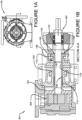
- FIGURE 1A illustrates an example pump 50, in an elevation, rear view from the pump's motor toward the pump rotor.
- FIGURE 1B illustrates one implementation of a system 100, showing the example pump 50 in a top a cut-away view, along the A-A line of FIGURE 1A .
- FIGURE 1C illustrates one implementation of a system 100, showing the example pump 50 in a close up of a portion of the top a cut-away view of FIGURE 1B .
- a one-piece, combination packing gland and bushing component 102 can be used to seat in a shaft casing 150 along a rotating pump shaft 152.
- the packing gland and bushing component 102 can comprise a proximal end 104 that is proximate a pump motor coupling portion 162 of the shaft 152. Further, the packing gland and bushing component 102 can comprise a distal end 106 that is distal from the pump motor coupling portion 162 of the shaft 152.
- the packing gland and bushing component 102 can comprise a packing gland portion 108 disposed at the proximal end 104.
- the packing gland portion 108 can provide for compression of packing material in the shaft casing 150.
- the packing gland and bushing component 102 can also comprise a bushing portion 110 that is disposed at the distal end 106.
- the bushing portion 110 can provide a bearing surface 114 for the rotating shaft 152.
- the bushing portion can comprise an inner gasket channel 116 that is disposed proximate a proximal end of the bushing portion 110.
- the inner gasket channel 116 can be used to hold a gasket between the inside of the bushing portion 110 and the rotating shaft 152 to mitigate leakage of a lubricant from the proximal end 104, from the inside of the bushing portion 110.
- the example system 100 can comprise packing material 112 that is disposed proximate the distal end 106 of the packing gland and bushing component 102.
- the packing material 112 can be used to mitigate leakage of a fluid from a pumping chamber 154. Further, in this implementation, the packing material 112 can be subjected to compression force provided by the packing gland and bushing component 102.
- the gland portion 104, of the packing gland and bushing component 102 can comprise two fastener couplers 302.
- the fastener couplers 302 can respectively be configured to receive a compression fastener 158 to facilitate compression of the packing material (e.g., against a packing retainer or rear seat of a packing chamber or shaft casing), such as by using the packing gland and bushing component 102.
- the pump can comprise a packing retainer, which may be removable from the pump rotor side of the shaft casing or packing chamber. In this way, for example, the packing material 112 may be removed (e.g., and replaced) without removal of the packing gland and bushing component 102.
- the combination packing gland and bushing component 102 may be used to replace current two-piece bushing and packing gland systems in the shaft casing of a fluid pump.
- two-piece packing gland systems which are often made of two different materials, can be more difficult to remove from the shaft casing, for maintenance, and/or replacement of packing material. That is, using the example system 100, both the packing gland and bushing portions 108, 110 can be removed at the same time; and a one-piece, combination packing gland and bushing component 102 can be easier and less costly to manufacture in a single unit (e.g., machined, formed, etc.).
- current and prior two-piece systems have two separate pieces that are manufactured separately (e.g., and sometimes using different materials), and may need to be removed separately.
- the location of the inner gasket channel 116, with an accompanying gasket e.g., O-ring
- FIGURES 2A, 2B , 3A, 3B , 4 , 5A, 5B, and 5C illustrate various views of one or more implementations of one or more portion of the example system 100, as may be utilized in an example pump 50.
- the packing gland and bushing component 102 can comprise an outer gasket channel 118 that is disposed proximate the proximal end 102 of the bushing portion 110.
- the outer gasket channel 118 can be used to hold an outer gasket 210 between the outside of the bushing portion 110 and a wall of the shaft casing 156.
- the outer gasket channel 118 with the outer gasket 210 can help mitigate leakage of lubricant (e.g., and/or pumped fluid) from the proximal end 104 of the packing gland and bushing component 102, around the external surface 204 of the bushing portion 110.
- lubricant e.g., and/or pumped fluid
- the packing gland and bushing component can comprise a lubricant channel 202 that is disposed around the external surface 204 of the bushing portion 110, distally on the bushing portion 110 from the inner gasket channel 116.
- the lubricant channel 202 can be configured to operably receive bushing lubricant 160, such as provided by a lubricant source (e.g., injector).
- the packing gland and bushing component 102 can comprise a lubricant port 206 that is disposed through a wall 306 of the bushing portion 110, between the lubricant channel 202 and the interior of the bushing 308.
- the lubricant port 206 can be configured to operably transport lubricant 160 from the lubricant channel 202 to the interior of the bushing portion 308.
- the pump may comprise a lubricant provider, such as lubrication pump, injector, or the like, that provides a lubricant source.
- the lubricant source can be fluidly coupled with a port located in the wall 156 of the shaft casing 150.
- the port located in the wall 156 of the shaft casing 150 may be aligned with the lubrication channel 202, thereby providing a source of lubricant to the lubrication channel 202.
- the lubrication port 206 can provide a fluid channel for the lubricant between the lubrication channel 202 and the interior of the bushing portion 308.
- the bearing surface 114 of the bushing portion 110 can be provided with lubrication, at least while the shaft 152 is operably rotating during operation of the pump 50.
- a location of the outer gasket channel 118, used with an accompanying gasket 210 can mitigate leakage of the lubricant to the proximal end 104 of the packing gland and bushing component 102, along its outer surface 204.
- the location of the inner gasket channel 116, used with an accompanying inner gasket 208 can mitigate leakage of the lubricant to the proximal end 104 of the packing gland and bushing component 102, along its inner surface (e.g., the bearing surface 114).
- the location of these gaskets 208, 218, in combination with the one-piece combination of the packing gland and bushing component 102 may allow for lubricant to be used at a higher pressure than prior.
- leakage of the pumped fluid from the pumping chamber 154 may also be mitigated by using higher lubricant pressures.
- the location of the gasket channel 116 and inner gasket 208 can provide a dynamic seal against the shaft 152.
- lubricant provided to the interior of the bushing portion 308 can help cool and lubricate the gasket 208.
- the gasket channel 116 and inner gasket 208 can also serve as a secondary containment to mitigate leakage from the pumping chamber 154, for example, if the packing material 112 would fail.
- the packing gland and bushing component 102 can comprise a packing gland and bushing removal component 304.
- the packing gland and bushing removal component 304 can be disposed on the packing gland portion 108 to facilitate removal of the packing gland and bushing component 102 from the pump shaft casing 150.
- the packing gland and bushing removal component 304 can comprise an access opening that allows a pulling tool to engage with the packing gland portion 108, to pull the packing gland and bushing component 102 from the pump shaft casing 150.
- the packing gland and bushing removal component 304 can comprise a threaded portion to further facilitate removal of the packing gland and bushing component 102.
- the access opening of the packing gland and bushing removal bushing removal component 304 to facilitate in removal.
- a pulling tool can be coupled with the jack screws to provide for easy removal of the packing gland and bushing component 102.
- FIGURES 6-11 illustrate one or more portions of an example device 600, in accordance with the invention, and one or more implementations of the example device 600 as used in an example pump 854.
- the example device 600 comprises a tubular portion 602.
- the tubular portion 602 comprises a distal end 604 that may be disposed adjacent a back seat 1052 of a pump shaft packing box 950.
- the example device 600 comprises a proximal end 606 that may be disposed adjacent a proximal end 952 of the pump shaft packing box 950. That is, for example, the length of the tubular portion 602 can be configured to fit (e.g., and fill entirely) the length of the pump shaft packing box 950.
- tubular portion 602 comprises an external diameter 702 that is sized to fit inside the pump shaft packing box 950, and an internal diameter 704 that is sized to receive a pump shaft 850. That is, the tubular portion 602 is configured to fit over the pump shaft 850, and to fit inside (e.g., and fill) the pump shaft packing box 950, such as in a slip-fit arrangement. In this way, for example, packing material may not be needed.
- the example device 600 comprises a flange 608 that is disposed at the proximal end 606 of the tubular portion 602.
- the flange comprises two fastener couplers 610, that are respectively configured to receive a fastener 852 (e.g., a compression fastener, such as 158 of FIGURE 1 ).
- the example device 600 comprises a first gasket channel 612 that is configured to receive a gasket.
- the first gasket channel 612 is disposed around the external surface 614 of tubular portion 602, proximate to the distal end 604.
- the example device 600 comprises a second gasket channel 616 that is configured to receive a gasket.
- the second gasket channel 616 is disposed around the external surface 614 of tubular portion 602 proximate to the proximal end 606.
- the example device 600 also comprises a third gasket channel 706 that is configured to receive a gasket.
- the third gasket channel 706 is disposed around the internal surface 618 of tubular portion 602, between the first gasket channel 612 and the second gasket channel 616.
- the example device 600 can comprise a fourth gasket channel 620 that is configured to receive a gasket.
- the fourth gasket channel 620 can be disposed around the internal surface 618 of tubular portion 602, proximate to the distal end 604. Further, in one implementation, the fourth gasket channel 620 can be disposed between the first gasket channel 612 and the distal end 604 of the tubular potion 602.
- a plurality of O-rings 902, 904, 906, 908 may be used as gaskets, to provide a slip-fit for the tubular portion on the pump shaft 850 in the pump shaft packing box 950.
- the plurality of O-rings can comprise a first O-ring 902 disposed in the first gasket channel 612; a second O-ring 904 disposed in the second gasket channel 616; and a third O-ring 906 disposed in the third gasket channel 706. Additionally, a fourth O-ring 908 can be disposed in the fourth gasket channel 620.
- the plurality of O-rings 902, 904, 906, 908 disposed in their respective gasket channels 612, 616, 706, 620 can not only facilitate the slip-fit of the tubular portion 602 on the shaft 850 in the packing box 950, but can also mitigate leakage of fluid.
- gaskets 906 and 908 may facilitate containment of lubricant 1050 between the shaft 850 and the inner surface 618 of the tubular portion 602 (e.g., the bearing surface); and may also mitigate leakage of pumped fluid along the inner surface 618 of the tubular portion 602 toward the proximal end 606.
- the gaskets 902 and 904 may facilitate containment of lubricant 1050 between the external surface 614 of the tubular portion 602 and the wall of the pump shaft packing box; and may further mitigate leakage of pumped fluid along the external surface 614 of the tubular portion 602 toward the proximal end 606.
- the proximal gasket 906 can provide a secondary containment of liquid from the pumping chamber (e.g., 154 of FIGURE 1 ) in the event that the distal gasket 908 were to fail.
- the example device 600 can comprise a lubrication channel 622 that is configured to operably receive lubricant.
- the lubrication channel 622 can be disposed around the external surface 614 of the tubular portion 602, between the first gasket channel 612 and the second gasket channel 616.
- the example device 600 can comprise a lubrication port 624 that is configured to operably transport lubricant 1050 between the lubrication channel 622 and the interior 618 of the tubular portion 602.
- the lubrication port 624 can be disposed through a wall 702 of the tubular portion 602, between the lubrication channel 622 and the interior 618 of the tubular portion 602.
- an external lubrication supply can be fluidly provided to the lubrication channel 622, which, in turn, fluidly provides the lubricant 1050 to the interior 618 of the tubular portion 602, by way of the lubrication port 624.
- the lubricant 1050 can be used to operably lubricate a bearing surface between the interior 618 of the tubular portion 602 and the pump shaft 850; and may also operably provide lubrication for the dynamic seals between the inner gaskets 906, 908 and the rotating pump shaft 850.
- the example device 600 can comprise a seal removal component 626 that is disposed on the flange 608.
- the seal removal component 626 can be configured to facilitate removal of the device 600 from the pump shaft packing box 950.
- the seal removal component 626 can comprise an access opening that allows a pulling tool to engage with the flange 608, to pull the example device 600 from the pump shaft packing box 950.
- the seal removal component 626 can comprise a threaded portion to further facilitate removal of the example device 600.
- the access opening of the seal removal component 626 may comprise internal threads that allows for engagement with an external threaded component.
- jack screws may be threaded into the seal removal component 626 to facilitate removal of the example device 600.
- a pulling tool can be coupled with the jack screws to provide for easy removal of the example device 600.
- a pump can be devised that provides for improved sealing of the pump shaft of the pump, and ease of maintenance of the pump seal.
- the pump 50 can comprise a pump shaft 152 that rotates.
- the rotation can be provided by a motor that is coupled to the shaft by way of a pump motor coupler 162.
- the pump 50 can comprise a pump rotor that is disposed in a pump chamber 154.
- the pump rotor 164 can be operably coupled with the pump shaft 152, and can be configured to move fluid as a result of the rotation of the shaft 152.
- the pump 50 can also comprise a shaft casing 150 that is disposed around the pump shaft 152 to hold fluid seal system 100.
- the pump 50 can comprise a fluid seal component 100 that is disposed between the pump shaft 152 and the shaft casing 150 to mitigate fluid leakage from the pump chamber 154.
- the fluid seal component 100 can comprise a one-piece, combination packing gland and bushing component 102 that comprises a proximal end 104 proximate the pump motor coupler 162, and a distal end 106 distal from the motor coupler 162.
- the packing gland and bushing component 102 can comprise a packing gland portion 108 at the proximal end 104.
- the gland portion 108 can comprise two fastener couplers 302, that are respectively configured to receive a compression fastener 158 to facilitate compression of packing material 112.
- the packing gland and bushing component 102 can also comprise a bushing portion 110 disposed at the distal end 106 that provides a bearing surface 114 for the rotating shaft 152. Further, the packing gland and bushing component 102 can comprise an inner gasket channel 116 that is disposed at a proximal end 104 of the interior 308 of the bushing portion 110. Additionally, the packing gland and bushing component 102 can comprise an inner gasket 208 that is disposed in the inner gasket channel 116 between the inside 308 of the bushing portion 110 and the rotating shaft 152. The inner gasket 208 can be configured to mitigate leakage of a lubricant from the inside of the bushing portion 110.
- the pump 50 can comprise packing material 112 that is disposed in the shaft casing 150 at the distal end 106 of the packing gland and bushing component 102.
- the packing material 112 can be subjected to compression force provided by the packing gland and bushing component 102, to mitigate leakage of fluid from the pumping chamber 154.
- the packing gland and bushing component 102 can comprise an outer gasket channel 118 that is disposed proximate the proximal end 104 of the bushing portion 110.
- the outer gasket channel 118 can be used to hold a gasket between the outside of the bushing portion 204 and a wall of the shaft casing 156.
- the outer gasket channel 118 can hold an outer gasket 210, such as an O-ring.
- the packing gland and bushing component 102 can comprise a lubricant channel 202 that is configured to operably receive bushing lubricant 160.
- the lubricant channel 202 can be disposed around the external surface 204 of the bushing portion 110 at a location that is distally from the inner gasket channel 116.
- a lubricant port 206 can be configure to operably transport lubricant 160 from the lubricant channel 202 to the interior 308 of the bushing portion 110, such as to the bearing surface 114.
- the lubricant port 206 can be disposed through a wall 306 of the bushing portion 110 between the lubricant channel 202 and the interior 308 of the bushing portion 110.
- the example 50 can comprise a threaded packing gland and bushing removal component 304 that is disposed on the packing gland portion 108.
- the threaded packing gland and bushing removal component 304 can be configured to facilitate removal of the packing gland and bushing component removal component from the pump shaft casing.
- a pulling tool or jack screws may be coupled with the packing gland and bushing removal component 304 for easy removal of the packing gland and bushing component 102 from the shaft casing 150.
- the word "exemplary” is used herein to mean serving as an example, instance or illustration. Any aspect or design described herein as “exemplary” is not necessarily to be construed as advantageous over other aspects or designs. Rather, use of the word exemplary is intended to present concepts in a concrete fashion.
- the term "or” is intended to mean an inclusive “or” rather than an exclusive “or.” That is, unless specified otherwise, or clear from context, "X employs A or B” is intended to mean any of the natural inclusive permutations. That is, if X employs A; X employs B; or X employs both A and B, then "X employs A or B" is satisfied under any of the foregoing instances.
- At least one of A and B and/or the like generally means A or B or both A and B.
- the articles “a” and “an” as used in this application and the appended claims may generally be construed to mean “one or more” unless specified otherwise or clear from context to be directed to a singular form.
Landscapes
- Engineering & Computer Science (AREA)
- General Engineering & Computer Science (AREA)
- Mechanical Engineering (AREA)
- Sealing Devices (AREA)
- Structures Of Non-Positive Displacement Pumps (AREA)
- Details And Applications Of Rotary Liquid Pumps (AREA)
- Sealing Of Bearings (AREA)
- Mechanical Sealing (AREA)
Description
- Fluid pumps used in a variety of settings often utilize a packing seal system, which can comprise packing material and a packing gland, to mitigate loss of the transported fluid from the fluid transport system. These sealing systems are typically implemented along a rotating shaft used to drive the pumping component. For example, packing material can be compressed against a back seat, on a rotating shaft, by the packing gland and follower components. Often, a separate bushing component may be disposed on the shaft, between the packing gland and packing material. In this way, for example, the compressed packing material, along with a pressurized lubricant and bushing, can help mitigate fluid loss along the shaft.
US 4 478 423 A discloses an improved T-ring wiper seal and seal carrier assembly for use in the fluid end of a reciprocating pump.
US 3 013 826 A discloses a packing assembly used to preventing fluid leakage around a moving shaft. - This Summary is provided to introduce a selection of concepts in a simplified form that are further described below in the Detailed Description. This Summary is not intended to identify key factors or essential features of the claimed subject matter, nor is it intended to be used to limit the scope of the claimed subject matter.
- One or more techniques and systems described herein can be utilized to help mitigate fluid loss or leakage from a fluid pump with a rotating shaft driving a pumping mechanism, such as in a gear pump, for example. In one implementation, a packing gland component and bushing component may be formed as a one-piece, packing gland-bushing component, instead of typical two-piece components. In this example, the packing gland-bushing component can have an internal seal that allows for use of lubricants at higher pressures. Further, in this implementation, a face of the packing gland portion may have removal components that allows for easier removal of the packing gland-bushing component from a pump shaft.
- As another example, the one-piece packing gland-bushing may be configured to be used without packing material, essentially comprising merely a bushing component. In this example, the packing gland-bushing component may have a slip-fit configuration with the shaft of the pump. For example, a plurality of O-rings may be used to provide a seal, and allow for pressurized lubricant to be introduced along the bushing portion, at higher pressures. In some configurations, this may allow for the elimination of packing material in the shaft seal.
- The invention concerns a device for sealing a pump shaft of a pump, according to claim 1, and a pump comprising such a device, according to claim 9. Further preferred embodiments are defined in the dependent claims.
- In one implementation of a system for sealing a pump shaft, a one-piece, combination packing gland and bushing component can be used to seat in a shaft casing along a rotating pump shaft. In this implementation, the packing gland and bushing component can comprise a proximal end that is situated on the shaft near a pump motor coupler portion of the shaft, and a distal end that is situated distally on the shaft from the pump motor coupler. The packing gland and bushing component can further comprise a packing gland portion at the proximal end to provide for compression of packing material in the shaft casing. Additionally, the packing gland and bushing component can comprise a bushing portion at the distal end in order to provide a bearing surface for the rotating shaft. In this implementation, the bushing portion can comprise an inner gasket channel that is disposed proximate a proximal end of the bushing portion. The inner gasket channel can be used hold a gasket between the inside of the bushing portion and the rotating shaft to mitigate leakage of a lubricant from the proximal end of the inside of the bushing portion. In this implementation, a packing material can be disposed proximate the distal end of the packing gland and bushing component to mitigate leakage of a fluid from a pumping chamber. The packing material can be subjected to compression force that is provided by the packing gland and bushing component.
- To the accomplishment of the foregoing and related ends, the following description and annexed drawings set forth certain illustrative aspects and implementations. These are indicative of but a few of the various ways in which one or more aspects may be employed. Other aspects, advantages and novel features of the disclosure will become apparent from the following detailed description when considered in conjunction with the annexed drawings.
-
-
FIGURE 1A is a component diagram illustrating a view of an example implementation of a pump where one or more portion of one or more systems described herein may be implemented. -
FIGURES 1B and1C are a component diagrams illustrating a cut-away view of an example implementation of a pump where anexample system 100, described herein, may be implemented. -
FIGURES 2A and 2B are component diagrams illustrating various views of one or more portions of one or more systems described herein. -
FIGURES 3A and 3B are component diagrams illustrating various views of one or more portions of one or more systems described herein. -
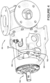
FIGURE 4 is a component diagram illustrating a view of an example implementation of a pump where one or more portion of one or more systems described herein may be implemented. -
FIGURE 5A is a component diagram illustrating a view of an example implementation of a pump where one or more portion of one or more systems described herein may be implemented. -
FIGURES 5B and 5C are a component diagrams illustrating a cut-away view of an example implementation of a pump where anexample system 100, described herein, may be implemented. -
FIGURE 6 is a component diagram illustrating a perspective view of anexample device 600 used to facilitate providing a seal in a pump. -
FIGURE 7 is a component diagram illustrating a perspective cut-away view of anexample device 600 used to facilitate providing a seal in a pump. -
FIGURE 8 is a component diagram illustrating a view of an example implementation of a pump where one or more portion of one or more devices described herein may be implemented. -
FIGURE 9 is a component diagram illustrating a cut-away view of an example implementation of a pump where one or more portion of one or more devices described herein may be implemented. -
FIGURE 10 is a component diagram illustrating a cut-away view of an example implementation of a pump where one or more portion of one or more devices described herein may be implemented. -
FIGURE 11 is a component diagram illustrating a close up of a cut-away view of an example implementation of a pump where one or more portion of one or more devices described herein may be implemented. - The claimed subject matter is now described with reference to the drawings, wherein like reference numerals are generally used to refer to like elements throughout. In the following description, for purposes of explanation, numerous specific details are set forth in order to provide a thorough understanding of the claimed subject matter. It may be evident, however, that the claimed subject matter may be practiced without these specific details. In other instances, structures and devices are shown in block diagram form in order to facilitate describing the claimed subject matter.
- As an example, pumps can be coupled to a motor by a rotating shaft. The motor typically rotates the shaft, which, in turn, rotates a pump rotor to move the fluids through coupled conduits. However, the location at which the rotating pump shaft enters the pumping chamber, comprising the pump rotor, offers a location for leakage of the pumped fluid from the pump chamber. A system can be devised for sealing a rotating pump shaft entrance to the pumping chamber. In one implementation, the pump can comprise a pump shaft casing, or pump shaft packing box, or the like, disposed proximally (e.g., proximally in relation to the connection of the shaft to the motor) from the entrance of the pump shaft to the pump chamber. In this implementation, the pump shaft is disposed inside the pump shaft casing, or pump shaft packing box, etc.
-
FIGURES 1-5 illustrate one implementation of an example system for sealing a rotating pump shaft in a pump.FIGURE 1A illustrates anexample pump 50, in an elevation, rear view from the pump's motor toward the pump rotor.FIGURE 1B illustrates one implementation of asystem 100, showing theexample pump 50 in a top a cut-away view, along the A-A line ofFIGURE 1A .FIGURE 1C illustrates one implementation of asystem 100, showing theexample pump 50 in a close up of a portion of the top a cut-away view ofFIGURE 1B . In this implementation, a one-piece, combination packing gland andbushing component 102 can be used to seat in ashaft casing 150 along a rotatingpump shaft 152. In this implementation, the packing gland andbushing component 102 can comprise aproximal end 104 that is proximate a pumpmotor coupling portion 162 of theshaft 152. Further, the packing gland andbushing component 102 can comprise adistal end 106 that is distal from the pumpmotor coupling portion 162 of theshaft 152. - Additionally, in this implementation, the packing gland and
bushing component 102 can comprise apacking gland portion 108 disposed at theproximal end 104. Thepacking gland portion 108 can provide for compression of packing material in theshaft casing 150. The packing gland andbushing component 102 can also comprise abushing portion 110 that is disposed at thedistal end 106. Thebushing portion 110 can provide abearing surface 114 for therotating shaft 152. In this implementation, the bushing portion can comprise aninner gasket channel 116 that is disposed proximate a proximal end of thebushing portion 110. Theinner gasket channel 116 can be used to hold a gasket between the inside of thebushing portion 110 and therotating shaft 152 to mitigate leakage of a lubricant from theproximal end 104, from the inside of thebushing portion 110. - As illustrated in
FIGURES 1B and1C , theexample system 100 can comprise packingmaterial 112 that is disposed proximate thedistal end 106 of the packing gland andbushing component 102. The packingmaterial 112 can be used to mitigate leakage of a fluid from apumping chamber 154. Further, in this implementation, the packingmaterial 112 can be subjected to compression force provided by the packing gland andbushing component 102. As illustrated inFIGURES 3A and 3B , with continued reference toFIGURES 1B and1C , in one implementation, thegland portion 104, of the packing gland andbushing component 102, can comprise twofastener couplers 302. In this implementation, thefastener couplers 302 can respectively be configured to receive acompression fastener 158 to facilitate compression of the packing material (e.g., against a packing retainer or rear seat of a packing chamber or shaft casing), such as by using the packing gland andbushing component 102. In one implementation, the pump can comprise a packing retainer, which may be removable from the pump rotor side of the shaft casing or packing chamber. In this way, for example, the packingmaterial 112 may be removed (e.g., and replaced) without removal of the packing gland andbushing component 102. - As an example, the combination packing gland and
bushing component 102 may be used to replace current two-piece bushing and packing gland systems in the shaft casing of a fluid pump. For example, two-piece packing gland systems, which are often made of two different materials, can be more difficult to remove from the shaft casing, for maintenance, and/or replacement of packing material. That is, using theexample system 100, both the packing gland andbushing portions bushing component 102 can be easier and less costly to manufacture in a single unit (e.g., machined, formed, etc.). Whereas current and prior two-piece systems have two separate pieces that are manufactured separately (e.g., and sometimes using different materials), and may need to be removed separately. Further, for example, the location of theinner gasket channel 116, with an accompanying gasket (e.g., O-ring), may allow for higher pressures of shaft lubricant pressure without causing typical lip seal failure of bushing found in current two-piece systems. -
FIGURES 2A, 2B ,3A, 3B ,4 ,5A, 5B, and 5C illustrate various views of one or more implementations of one or more portion of theexample system 100, as may be utilized in anexample pump 50. In one implementation, the packing gland andbushing component 102 can comprise anouter gasket channel 118 that is disposed proximate theproximal end 102 of thebushing portion 110. In this implementation, theouter gasket channel 118 can be used to hold anouter gasket 210 between the outside of thebushing portion 110 and a wall of theshaft casing 156. As an example, theouter gasket channel 118 with theouter gasket 210 can help mitigate leakage of lubricant (e.g., and/or pumped fluid) from theproximal end 104 of the packing gland andbushing component 102, around theexternal surface 204 of thebushing portion 110. - In one implementation, as illustrated in
FIGURES 2A and 2B , the packing gland and bushing component can comprise alubricant channel 202 that is disposed around theexternal surface 204 of thebushing portion 110, distally on thebushing portion 110 from theinner gasket channel 116. Thelubricant channel 202 can be configured to operably receivebushing lubricant 160, such as provided by a lubricant source (e.g., injector). Further, in this implementation, the packing gland andbushing component 102 can comprise alubricant port 206 that is disposed through awall 306 of thebushing portion 110, between thelubricant channel 202 and the interior of thebushing 308. Thelubricant port 206 can be configured to operablytransport lubricant 160 from thelubricant channel 202 to the interior of thebushing portion 308. - As one example, the pump (e.g., 50) may comprise a lubricant provider, such as lubrication pump, injector, or the like, that provides a lubricant source. In this example, the lubricant source can be fluidly coupled with a port located in the
wall 156 of theshaft casing 150. Further, in this example, the port located in thewall 156 of theshaft casing 150 may be aligned with thelubrication channel 202, thereby providing a source of lubricant to thelubrication channel 202. Additionally, thelubrication port 206 can provide a fluid channel for the lubricant between thelubrication channel 202 and the interior of thebushing portion 308. In this way, for example, the bearingsurface 114 of thebushing portion 110 can be provided with lubrication, at least while theshaft 152 is operably rotating during operation of thepump 50. - As one example, a location of the
outer gasket channel 118, used with an accompanyinggasket 210, can mitigate leakage of the lubricant to theproximal end 104 of the packing gland andbushing component 102, along itsouter surface 204. Further, in this example, the location of theinner gasket channel 116, used with an accompanyinginner gasket 208, can mitigate leakage of the lubricant to theproximal end 104 of the packing gland andbushing component 102, along its inner surface (e.g., the bearing surface 114). Additionally, the location of thesegaskets 208, 218, in combination with the one-piece combination of the packing gland andbushing component 102 may allow for lubricant to be used at a higher pressure than prior. In this way, leakage of the pumped fluid from thepumping chamber 154 may also be mitigated by using higher lubricant pressures. As one example, the location of thegasket channel 116 andinner gasket 208 can provide a dynamic seal against theshaft 152. In this example, lubricant provided to the interior of thebushing portion 308 can help cool and lubricate thegasket 208. Thegasket channel 116 andinner gasket 208 can also serve as a secondary containment to mitigate leakage from thepumping chamber 154, for example, if the packingmaterial 112 would fail. - In one implementation, as illustrated in
FIGURES 3A, 3B , and4 , the packing gland andbushing component 102 can comprise a packing gland andbushing removal component 304. In one implementation, the packing gland andbushing removal component 304 can be disposed on thepacking gland portion 108 to facilitate removal of the packing gland andbushing component 102 from thepump shaft casing 150. As an example, the packing gland andbushing removal component 304 can comprise an access opening that allows a pulling tool to engage with thepacking gland portion 108, to pull the packing gland andbushing component 102 from thepump shaft casing 150. - In one implementation, the packing gland and
bushing removal component 304 can comprise a threaded portion to further facilitate removal of the packing gland andbushing component 102. For example, the access opening of the packing gland and bushing removalbushing removal component 304 to facilitate in removal. As another example, a pulling tool can be coupled with the jack screws to provide for easy removal of the packing gland andbushing component 102. - In one aspect, a device may be devised that can be used for sealing a pump shaft of a pump.
FIGURES 6-11 illustrate one or more portions of anexample device 600, in accordance with the invention, and one or more implementations of theexample device 600 as used in anexample pump 854. According to the invention, as illustrated inFIGURES 6-10 , theexample device 600 comprises atubular portion 602. Thetubular portion 602 comprises adistal end 604 that may be disposed adjacent aback seat 1052 of a pumpshaft packing box 950. Further, according to the invention, theexample device 600 comprises aproximal end 606 that may be disposed adjacent aproximal end 952 of the pumpshaft packing box 950. That is, for example, the length of thetubular portion 602 can be configured to fit (e.g., and fill entirely) the length of the pumpshaft packing box 950. - According to the invention,
tubular portion 602 comprises anexternal diameter 702 that is sized to fit inside the pumpshaft packing box 950, and aninternal diameter 704 that is sized to receive apump shaft 850. That is, thetubular portion 602 is configured to fit over thepump shaft 850, and to fit inside (e.g., and fill) the pumpshaft packing box 950, such as in a slip-fit arrangement. In this way, for example, packing material may not be needed. - The
example device 600 comprises aflange 608 that is disposed at theproximal end 606 of thetubular portion 602. According to the invention, the flange comprises twofastener couplers 610, that are respectively configured to receive a fastener 852 (e.g., a compression fastener, such as 158 ofFIGURE 1 ). Further, theexample device 600 comprises afirst gasket channel 612 that is configured to receive a gasket. Thefirst gasket channel 612 is disposed around theexternal surface 614 oftubular portion 602, proximate to thedistal end 604. Additionally, theexample device 600 comprises asecond gasket channel 616 that is configured to receive a gasket. Thesecond gasket channel 616 is disposed around theexternal surface 614 oftubular portion 602 proximate to theproximal end 606. Theexample device 600 also comprises athird gasket channel 706 that is configured to receive a gasket. Thethird gasket channel 706 is disposed around theinternal surface 618 oftubular portion 602, between thefirst gasket channel 612 and thesecond gasket channel 616. - In one implementation, the
example device 600 can comprise afourth gasket channel 620 that is configured to receive a gasket. Thefourth gasket channel 620 can be disposed around theinternal surface 618 oftubular portion 602, proximate to thedistal end 604. Further, in one implementation, thefourth gasket channel 620 can be disposed between thefirst gasket channel 612 and thedistal end 604 of thetubular potion 602. In one implementation, a plurality of O-rings pump shaft 850 in the pumpshaft packing box 950. In this implementation, the plurality of O-rings can comprise a first O-ring 902 disposed in thefirst gasket channel 612; a second O-ring 904 disposed in thesecond gasket channel 616; and a third O-ring 906 disposed in thethird gasket channel 706. Additionally, a fourth O-ring 908 can be disposed in thefourth gasket channel 620. - As an example, as illustrated in
FIGURES 9-11 , the plurality of O-rings respective gasket channels tubular portion 602 on theshaft 850 in thepacking box 950, but can also mitigate leakage of fluid. For example,gaskets lubricant 1050 between theshaft 850 and theinner surface 618 of the tubular portion 602 (e.g., the bearing surface); and may also mitigate leakage of pumped fluid along theinner surface 618 of thetubular portion 602 toward theproximal end 606. As another example, thegaskets lubricant 1050 between theexternal surface 614 of thetubular portion 602 and the wall of the pump shaft packing box; and may further mitigate leakage of pumped fluid along theexternal surface 614 of thetubular portion 602 toward theproximal end 606. As another example, theproximal gasket 906 can provide a secondary containment of liquid from the pumping chamber (e.g., 154 ofFIGURE 1 ) in the event that thedistal gasket 908 were to fail. - The
example device 600 can comprise alubrication channel 622 that is configured to operably receive lubricant. In this implementation, thelubrication channel 622 can be disposed around theexternal surface 614 of thetubular portion 602, between thefirst gasket channel 612 and thesecond gasket channel 616. Further, theexample device 600 can comprise alubrication port 624 that is configured to operablytransport lubricant 1050 between thelubrication channel 622 and theinterior 618 of thetubular portion 602. In this implementation, thelubrication port 624 can be disposed through awall 702 of thetubular portion 602, between thelubrication channel 622 and theinterior 618 of thetubular portion 602. In this way, for example, an external lubrication supply can be fluidly provided to thelubrication channel 622, which, in turn, fluidly provides thelubricant 1050 to theinterior 618 of thetubular portion 602, by way of thelubrication port 624. Thelubricant 1050, for example, can be used to operably lubricate a bearing surface between the interior 618 of thetubular portion 602 and thepump shaft 850; and may also operably provide lubrication for the dynamic seals between theinner gaskets rotating pump shaft 850. - In one implementation, the
example device 600 can comprise aseal removal component 626 that is disposed on theflange 608. Theseal removal component 626 can be configured to facilitate removal of thedevice 600 from the pumpshaft packing box 950. For example, theseal removal component 626 can comprise an access opening that allows a pulling tool to engage with theflange 608, to pull theexample device 600 from the pumpshaft packing box 950. As another example, theseal removal component 626 can comprise a threaded portion to further facilitate removal of theexample device 600. For example, the access opening of theseal removal component 626 may comprise internal threads that allows for engagement with an external threaded component. In on example, jack screws may be threaded into theseal removal component 626 to facilitate removal of theexample device 600. As another example, a pulling tool can be coupled with the jack screws to provide for easy removal of theexample device 600. - In one aspect, a pump can be devised that provides for improved sealing of the pump shaft of the pump, and ease of maintenance of the pump seal. In this aspect, in one implementation, as illustrated in
FIGURES 1-5 , thepump 50 can comprise apump shaft 152 that rotates. For example, the rotation can be provided by a motor that is coupled to the shaft by way of apump motor coupler 162. Further, thepump 50 can comprise a pump rotor that is disposed in apump chamber 154. Thepump rotor 164 can be operably coupled with thepump shaft 152, and can be configured to move fluid as a result of the rotation of theshaft 152. Thepump 50 can also comprise ashaft casing 150 that is disposed around thepump shaft 152 to holdfluid seal system 100. - In this aspect, in one implementation, the
pump 50 can comprise afluid seal component 100 that is disposed between thepump shaft 152 and theshaft casing 150 to mitigate fluid leakage from thepump chamber 154. Thefluid seal component 100 can comprise a one-piece, combination packing gland andbushing component 102 that comprises aproximal end 104 proximate thepump motor coupler 162, and adistal end 106 distal from themotor coupler 162. The packing gland andbushing component 102 can comprise apacking gland portion 108 at theproximal end 104. Thegland portion 108 can comprise twofastener couplers 302, that are respectively configured to receive acompression fastener 158 to facilitate compression of packingmaterial 112. - The packing gland and
bushing component 102 can also comprise abushing portion 110 disposed at thedistal end 106 that provides abearing surface 114 for therotating shaft 152. Further, the packing gland andbushing component 102 can comprise aninner gasket channel 116 that is disposed at aproximal end 104 of theinterior 308 of thebushing portion 110. Additionally, the packing gland andbushing component 102 can comprise aninner gasket 208 that is disposed in theinner gasket channel 116 between the inside 308 of thebushing portion 110 and therotating shaft 152. Theinner gasket 208 can be configured to mitigate leakage of a lubricant from the inside of thebushing portion 110. In one implementation, thepump 50 can comprise packingmaterial 112 that is disposed in theshaft casing 150 at thedistal end 106 of the packing gland andbushing component 102. The packingmaterial 112 can be subjected to compression force provided by the packing gland andbushing component 102, to mitigate leakage of fluid from thepumping chamber 154. - In one implementation, in this aspect, the packing gland and
bushing component 102 can comprise anouter gasket channel 118 that is disposed proximate theproximal end 104 of thebushing portion 110. Theouter gasket channel 118 can be used to hold a gasket between the outside of thebushing portion 204 and a wall of theshaft casing 156. As an example, theouter gasket channel 118 can hold anouter gasket 210, such as an O-ring. - Further, the packing gland and
bushing component 102 can comprise alubricant channel 202 that is configured to operably receivebushing lubricant 160. In this implementation, thelubricant channel 202 can be disposed around theexternal surface 204 of thebushing portion 110 at a location that is distally from theinner gasket channel 116. Further, alubricant port 206 can be configure tooperably transport lubricant 160 from thelubricant channel 202 to theinterior 308 of thebushing portion 110, such as to thebearing surface 114. Thelubricant port 206 can be disposed through awall 306 of thebushing portion 110 between thelubricant channel 202 and theinterior 308 of thebushing portion 110. - In one implementation, in this aspect, the example 50 can comprise a threaded packing gland and
bushing removal component 304 that is disposed on thepacking gland portion 108. The threaded packing gland andbushing removal component 304 can be configured to facilitate removal of the packing gland and bushing component removal component from the pump shaft casing. For example, a pulling tool or jack screws, may be coupled with the packing gland andbushing removal component 304 for easy removal of the packing gland andbushing component 102 from theshaft casing 150. - Moreover, the word "exemplary" is used herein to mean serving as an example, instance or illustration. Any aspect or design described herein as "exemplary" is not necessarily to be construed as advantageous over other aspects or designs. Rather, use of the word exemplary is intended to present concepts in a concrete fashion. As used in this application, the term "or" is intended to mean an inclusive "or" rather than an exclusive "or." That is, unless specified otherwise, or clear from context, "X employs A or B" is intended to mean any of the natural inclusive permutations. That is, if X employs A; X employs B; or X employs both A and B, then "X employs A or B" is satisfied under any of the foregoing instances. Further, At least one of A and B and/or the like generally means A or B or both A and B. In addition, the articles "a" and "an" as used in this application and the appended claims may generally be construed to mean "one or more" unless specified otherwise or clear from context to be directed to a singular form.
- Although the subject matter has been described in language specific to structural features and/or methodological acts, it is to be understood that the subject matter defined in the appended claims is not necessarily limited to the specific features or acts described above. Rather, the specific features and acts described above are disclosed as example forms of implementing the claims.
- Also, although the disclosure has been shown and described with respect to one or more implementations, equivalent alterations and modifications will occur to others skilled in the art based upon a reading and understanding of this specification and the annexed drawings. The disclosure includes all such modifications and alterations and is limited only by the scope of the following claims. In particular regard to the various functions performed by the above described components (e.g., elements, resources, etc.), the terms used to describe such components are intended to correspond, unless otherwise indicated, to any component which performs the specified function of the described component (e.g., that is functionally equivalent), even though not structurally equivalent to the disclosed structure which performs the function in the herein illustrated exemplary implementations of the disclosure. In addition, while a particular feature of the disclosure may have been disclosed with respect to only one of several implementations, such feature may be combined with one or more other features of the other implementations as may be desired and advantageous for any given or particular application. Furthermore, to the extent that the terms "includes," "having," "has," "with," or variants thereof are used in either the detailed description or the claims, such terms are intended to be inclusive in a manner similar to the term "comprising."
- The implementations have been described, hereinabove. It will be apparent to those skilled in the art that the above methods and apparatuses may incorporate changes and modifications without departing from the general scope of this invention. It is intended to include all such modifications and alterations in so far as they come within the scope of the appended claims.
Claims (15)
- A device for sealing a pump shaft of a pump (50), comprising:a tubular portion (602) comprising:a distal end (604) to be disposed adjacent a back seat (1052) of a pump shaft packing box (950);a proximal end (606) to be disposed adjacent a proximal end (652) of the pump shaft packing box (950);an external diameter (702) sized to fit inside the pump shaft packing box (950); andan internal diameter (704) sized to receive a rotating pump shaft (850);a flange (608) disposed at the proximal end (606) of the tubular portion (602), the flange comprising two fastener couplers (610), respectively to receive a fastener (852);wherein the tubular portion (602) and the flange (608) are formed as one piece;a first gasket channel (612) to receive a gasket, the first gasket channel disposed around the external surface (614) of tubular portion (602) proximate the distal end (604);a second gasket channel (616) to receive a gasket, the second gasket channel disposed around the external surface (614) of tubular portion (602) proximate the proximal end (606); anda third gasket channel (706) to receive a gasket, the third gasket channel disposed around the internal surface (618) of tubular portion (602) between the first gasket channel (612) and the second gasket channel (616).
- The device of claim 1, comprising a fourth gasket channel (620) to receive a gasket, the fourth gasket channel disposed around the internal surface (618) of tubular portion (602) proximate the distal end (604).
- The device of claim 2, wherein the fourth gasket channel (618) is disposed between the first gasket channel (612) and the distal end (604) of the tubular portion (602).
- The device of claim 1, comprising a lubrication channel (622) to operably receive lubricant, the lubrication channel disposed around the external surface (614) of the tubular portion between the first gasket channel (612) and the second gasket channel (616).
- The device of claim 4, comprising a lubrication port (624) to operably transport lubricant between the lubrication channel (622) and the interior (618) of the tubular portion (602), the lubrication port disposed through a wall of the tubular portion between the lubrication channel and the interior of the tubular portion.
- The device of claim 1, comprising a plurality of O-rings to provide a slip-fit for the tubular portion on the pump shaft in the pump shaft packing box, the plurality of O-rings comprising:a first O-ring (902) disposed in the first gasket channel (612);a second O-ring (904) disposed in the second gasket channel (616); anda third O-ring (906) disposed in the third gasket channel (706).
- The device of claim 3, comprising a fourth O-ring (908) disposed in the fourth gasket channel (620).
- The device of claim 1, comprising a seal removal component (626) disposed on the flange (608), to facilitate removal of the device from the pump shaft packing box (950).
- A pump (854), comprising:a pump shaft (850) configured to rotate;a pump shaft packing box (950) having a back seat (1052) and a proximal end (652);a device for sealing the pump shaft (850) of the pump (854), the device comprising:a tubular portion (602) comprising:a distal end (604) disposed adjacent the back seat (1052) of the pump shaft packing box (950);a proximal end (606) disposed adjacent the proximal end (652) of the pump shaft packing box (950);wherein the tubular portion is fitted over the pump shaft (850) and inside the pump shaft packing box (950);a flange (608) disposed at the proximal end (606) of the tubular portion (602), the flange comprising two fastener couplers (610), respectively to receive a fastener (852);wherein the tubular portion (602) and the flange (608) are formed as one piece;a first gasket channel (612) to receive a gasket, the first gasket channel disposed around the external surface (614) of tubular portion (602) proximate the distal end (604);a first O-ring (902) disposed in the first gasket channel (612);a second gasket channel (616) to receive a gasket, the second gasket channel disposed around the external surface (614) of tubular portion (602) proximate the proximal end (606);a second O-ring (904) disposed in the second gasket channel (616);a third gasket channel (706) to receive a gasket, the third gasket channel disposed around the internal surface (618) of tubular portion (602) between the first gasket channel (612) and the second gasket channel (616); anda third O-ring (906) disposed in the third gasket channel (706);wherein the plurality of O-rings (902, 904, 906) provides a slip-fit for the tubular portion (602) on the pump shaft in the pump shaft packing box (950).
- The pump of claim 9, wherein the device comprises a fourth gasket channel (620) to receive a gasket, the fourth gasket channel disposed around the internal surface (618) of tubular portion (602) proximate the distal end (604).
- The pump of claim 10, wherein the fourth gasket channel (618) is disposed between the first gasket channel (612) and the distal end (604) of the tubular portion (602).
- The pump of any of claims 9 to 11, wherein the device comprises a lubrication channel (622) to operably receive lubricant, the lubrication channel disposed around the external surface (614) of the tubular portion between the first gasket channel (612) and the second gasket channel (616).
- The pump of claim 12, wherein the device comprises a lubrication port (624) to operably transport lubricant between the lubrication channel (622) and the interior (618) of the tubular portion (602), the lubrication port disposed through a wall of the tubular portion between the lubrication channel and the interior of the tubular portion.
- The pump of claim 10 or 11, wherein the device comprises a fourth O-ring (908) disposed in the fourth gasket channel (620).
- The pump of any of claims 9 to 14, wherein the device comprises a seal removal component (626) disposed on the flange (608), to facilitate removal of the device from the pump shaft packing box (950).
Applications Claiming Priority (3)
| Application Number | Priority Date | Filing Date | Title |
|---|---|---|---|
| US201662406472P | 2016-10-11 | 2016-10-11 | |
| US201762474217P | 2017-03-21 | 2017-03-21 | |
| PCT/US2017/056162 WO2018071555A1 (en) | 2016-10-11 | 2017-10-11 | Pump shaft packing gland and bushing |
Publications (2)
| Publication Number | Publication Date |
|---|---|
| EP3526496A1 EP3526496A1 (en) | 2019-08-21 |
| EP3526496B1 true EP3526496B1 (en) | 2024-12-18 |
Family
ID=60183134
Family Applications (1)
| Application Number | Title | Priority Date | Filing Date |
|---|---|---|---|
| EP17790920.7A Active EP3526496B1 (en) | 2016-10-11 | 2017-10-11 | Pump shaft packing gland and bushing |
Country Status (11)
| Country | Link |
|---|---|
| US (1) | US10760685B2 (en) |
| EP (1) | EP3526496B1 (en) |
| CA (1) | CA3040174C (en) |
| CL (1) | CL2019000939A1 (en) |
| CO (1) | CO2019004406A2 (en) |
| DK (1) | DK3526496T3 (en) |
| EC (1) | ECSP19033154A (en) |
| ES (1) | ES3008580T3 (en) |
| MX (1) | MX2019003974A (en) |
| PL (1) | PL3526496T3 (en) |
| WO (1) | WO2018071555A1 (en) |
Families Citing this family (7)
| Publication number | Priority date | Publication date | Assignee | Title |
|---|---|---|---|---|
| US11566616B2 (en) * | 2016-10-11 | 2023-01-31 | Viking Pump, Inc. | Pump shaft packing gland and bushing |
| CN112313435B (en) | 2018-06-18 | 2024-08-23 | 维京帕公司 | Double seal lubricated gland and swivel sleeve |
| US11739843B2 (en) | 2020-03-04 | 2023-08-29 | Seal-Ryt Corp. | Bearing extraction from a stuffing box of a rotary mechanical device |
| US11131317B1 (en) * | 2020-10-03 | 2021-09-28 | Ned T Foxglove | Hydraulic ram used for pump packing |
| US11703063B2 (en) | 2020-11-25 | 2023-07-18 | Viking Pump, Inc. | Pump gland with rotary dynamic seal |
| DE102021112742A1 (en) * | 2021-05-17 | 2022-11-17 | Hammelmann GmbH | Sealing device for a rod |
| EP4594659A1 (en) * | 2022-09-28 | 2025-08-06 | Viking Pump, Inc. | Rotating pump shaft barrier seal |
Citations (3)
| Publication number | Priority date | Publication date | Assignee | Title |
|---|---|---|---|---|
| US3975026A (en) * | 1975-02-14 | 1976-08-17 | Johns-Manville Corporation | Sealing cartridge for rotating shafts |
| US6382940B1 (en) * | 2000-07-18 | 2002-05-07 | George H. Blume | High pressure plunger pump housing and packing |
| CN103759010A (en) * | 2014-01-21 | 2014-04-30 | 中国成达工程有限公司 | Packing shaft seal structure for high-pressure reciprocation pump |
Family Cites Families (12)
| Publication number | Priority date | Publication date | Assignee | Title |
|---|---|---|---|---|
| US2486939A (en) * | 1944-08-02 | 1949-11-01 | Phillips Petroleum Co | Stuffing box |
| US3013826A (en) * | 1957-12-30 | 1961-12-19 | Douglas O Johnson | Packing assembly |
| US4440404A (en) * | 1982-08-09 | 1984-04-03 | Halliburton Company | Packing arrangement |
| US4478423A (en) * | 1984-04-18 | 1984-10-23 | Halliburton Company | Oil seal and unitized seal carrier for reciprocating shaft |
| JP2001248734A (en) * | 2000-03-07 | 2001-09-14 | Kurimoto Ltd | Sealing device for shaft such as valve stem |
| CA2366696A1 (en) * | 2002-01-03 | 2003-07-03 | Paul Hughes | Externally mountable spiral bushing |
| US6834862B2 (en) * | 2002-01-23 | 2004-12-28 | Mark R. Wilkinson | Shaft sealing system for a rotary mechanical device |
| JP2003227570A (en) * | 2002-02-05 | 2003-08-15 | Sumitomo Heavy Ind Ltd | Shaft sealing device |
| US20070273105A1 (en) * | 2004-03-11 | 2007-11-29 | Stanton Eddie N | Packing cartridges and pressure-dampening and voc-absorbing elements for plunger-type pumps |
| US8511219B2 (en) * | 2007-03-28 | 2013-08-20 | Clyde Union Inc. | Zero emissions reciprocating pump |
| US9188242B2 (en) | 2012-05-08 | 2015-11-17 | Control Components, Inc. | Low diffusivity barrier fluid packing system |
| US10072758B2 (en) * | 2015-11-09 | 2018-09-11 | Seal Ryt Corporation | Stuffing box body with integral diverted lantern ring |
-
2017
- 2017-10-11 ES ES17790920T patent/ES3008580T3/en active Active
- 2017-10-11 PL PL17790920.7T patent/PL3526496T3/en unknown
- 2017-10-11 WO PCT/US2017/056162 patent/WO2018071555A1/en not_active Ceased
- 2017-10-11 DK DK17790920.7T patent/DK3526496T3/en active
- 2017-10-11 US US15/730,347 patent/US10760685B2/en active Active
- 2017-10-11 CA CA3040174A patent/CA3040174C/en active Active
- 2017-10-11 EP EP17790920.7A patent/EP3526496B1/en active Active
- 2017-10-11 MX MX2019003974A patent/MX2019003974A/en unknown
-
2019
- 2019-04-08 CL CL2019000939A patent/CL2019000939A1/en unknown
- 2019-04-29 CO CONC2019/0004406A patent/CO2019004406A2/en unknown
- 2019-05-10 EC ECSENADI201933154A patent/ECSP19033154A/en unknown
Patent Citations (3)
| Publication number | Priority date | Publication date | Assignee | Title |
|---|---|---|---|---|
| US3975026A (en) * | 1975-02-14 | 1976-08-17 | Johns-Manville Corporation | Sealing cartridge for rotating shafts |
| US6382940B1 (en) * | 2000-07-18 | 2002-05-07 | George H. Blume | High pressure plunger pump housing and packing |
| CN103759010A (en) * | 2014-01-21 | 2014-04-30 | 中国成达工程有限公司 | Packing shaft seal structure for high-pressure reciprocation pump |
Also Published As
| Publication number | Publication date |
|---|---|
| EP3526496A1 (en) | 2019-08-21 |
| CO2019004406A2 (en) | 2019-07-31 |
| CA3040174A1 (en) | 2018-04-19 |
| US20180100583A1 (en) | 2018-04-12 |
| WO2018071555A1 (en) | 2018-04-19 |
| DK3526496T3 (en) | 2025-01-13 |
| ES3008580T3 (en) | 2025-03-24 |
| CA3040174C (en) | 2023-03-28 |
| CL2019000939A1 (en) | 2019-09-06 |
| MX2019003974A (en) | 2019-08-12 |
| US10760685B2 (en) | 2020-09-01 |
| ECSP19033154A (en) | 2019-07-31 |
| PL3526496T3 (en) | 2025-04-28 |
Similar Documents
| Publication | Publication Date | Title |
|---|---|---|
| US10760685B2 (en) | Pump shaft packing gland and bushing | |
| US11662027B2 (en) | Double seal lubricated packing gland and rotating sleeve | |
| US11566616B2 (en) | Pump shaft packing gland and bushing | |
| US6685191B2 (en) | Mechanical seal for rotating shaft | |
| DE112007002151T5 (en) | Seal for a turbine engine | |
| US9341175B2 (en) | Pump seal | |
| KR102055319B1 (en) | Oil free screw compressor | |
| US20060035746A1 (en) | Drive shaft assembly and method of separation | |
| CN212928176U (en) | System and device for sealing pump shaft, and pump | |
| CA2969760C (en) | Bearing isolator seal with enhanced rotor drive coupling | |
| CN106949086B (en) | A combined mechanical seal device | |
| US9927032B2 (en) | Direct drive assembly for pump assembly | |
| US12429137B2 (en) | Rotating pump shaft barrier seal | |
| US20240102471A1 (en) | Universal pump bracket | |
| US20170299060A1 (en) | Packing gland follower | |
| US20130069319A1 (en) | Remotely adjustable shaft seal | |
| HK40039239A (en) | Double seal lubricated packing gland and rotating sleeve | |
| FI120215B (en) | Pump seal part for use with pump bearing part | |
| CA2870963C (en) | Direct drive assembly for pump assembly | |
| HK40039239B (en) | Double seal lubricated packing gland and rotating sleeve |
Legal Events
| Date | Code | Title | Description |
|---|---|---|---|
| STAA | Information on the status of an ep patent application or granted ep patent |
Free format text: STATUS: UNKNOWN |
|
| STAA | Information on the status of an ep patent application or granted ep patent |
Free format text: STATUS: THE INTERNATIONAL PUBLICATION HAS BEEN MADE |
|
| PUAI | Public reference made under article 153(3) epc to a published international application that has entered the european phase |
Free format text: ORIGINAL CODE: 0009012 |
|
| STAA | Information on the status of an ep patent application or granted ep patent |
Free format text: STATUS: REQUEST FOR EXAMINATION WAS MADE |
|
| 17P | Request for examination filed |
Effective date: 20190412 |
|
| AK | Designated contracting states |
Kind code of ref document: A1 Designated state(s): AL AT BE BG CH CY CZ DE DK EE ES FI FR GB GR HR HU IE IS IT LI LT LU LV MC MK MT NL NO PL PT RO RS SE SI SK SM TR |
|
| AX | Request for extension of the european patent |
Extension state: BA ME |
|
| DAV | Request for validation of the european patent (deleted) | ||
| DAX | Request for extension of the european patent (deleted) | ||
| STAA | Information on the status of an ep patent application or granted ep patent |
Free format text: STATUS: EXAMINATION IS IN PROGRESS |
|
| 17Q | First examination report despatched |
Effective date: 20201110 |
|
| GRAP | Despatch of communication of intention to grant a patent |
Free format text: ORIGINAL CODE: EPIDOSNIGR1 |
|
| STAA | Information on the status of an ep patent application or granted ep patent |
Free format text: STATUS: GRANT OF PATENT IS INTENDED |
|
| INTG | Intention to grant announced |
Effective date: 20221024 |
|
| GRAJ | Information related to disapproval of communication of intention to grant by the applicant or resumption of examination proceedings by the epo deleted |
Free format text: ORIGINAL CODE: EPIDOSDIGR1 |
|
| STAA | Information on the status of an ep patent application or granted ep patent |
Free format text: STATUS: EXAMINATION IS IN PROGRESS |
|
| INTC | Intention to grant announced (deleted) | ||
| P01 | Opt-out of the competence of the unified patent court (upc) registered |
Effective date: 20230514 |
|
| GRAP | Despatch of communication of intention to grant a patent |
Free format text: ORIGINAL CODE: EPIDOSNIGR1 |
|
| STAA | Information on the status of an ep patent application or granted ep patent |
Free format text: STATUS: GRANT OF PATENT IS INTENDED |
|
| INTG | Intention to grant announced |
Effective date: 20240710 |
|
| GRAS | Grant fee paid |
Free format text: ORIGINAL CODE: EPIDOSNIGR3 |
|
| GRAA | (expected) grant |
Free format text: ORIGINAL CODE: 0009210 |
|
| STAA | Information on the status of an ep patent application or granted ep patent |
Free format text: STATUS: THE PATENT HAS BEEN GRANTED |
|
| AK | Designated contracting states |
Kind code of ref document: B1 Designated state(s): AL AT BE BG CH CY CZ DE DK EE ES FI FR GB GR HR HU IE IS IT LI LT LU LV MC MK MT NL NO PL PT RO RS SE SI SK SM TR |
|
| REG | Reference to a national code |
Ref country code: GB Ref legal event code: FG4D |
|
| REG | Reference to a national code |
Ref country code: CH Ref legal event code: EP |
|
| REG | Reference to a national code |
Ref country code: DE Ref legal event code: R096 Ref document number: 602017086843 Country of ref document: DE |
|
| REG | Reference to a national code |
Ref country code: DK Ref legal event code: T3 Effective date: 20250109 |
|
| REG | Reference to a national code |
Ref country code: IE Ref legal event code: FG4D |
|
| REG | Reference to a national code |
Ref country code: NL Ref legal event code: FP |
|
| REG | Reference to a national code |
Ref country code: ES Ref legal event code: FG2A Ref document number: 3008580 Country of ref document: ES Kind code of ref document: T3 Effective date: 20250324 |
|
| REG | Reference to a national code |
Ref country code: LT Ref legal event code: MG9D |
|
| PG25 | Lapsed in a contracting state [announced via postgrant information from national office to epo] |
Ref country code: HR Free format text: LAPSE BECAUSE OF FAILURE TO SUBMIT A TRANSLATION OF THE DESCRIPTION OR TO PAY THE FEE WITHIN THE PRESCRIBED TIME-LIMIT Effective date: 20241218 |
|
| PG25 | Lapsed in a contracting state [announced via postgrant information from national office to epo] |
Ref country code: FI Free format text: LAPSE BECAUSE OF FAILURE TO SUBMIT A TRANSLATION OF THE DESCRIPTION OR TO PAY THE FEE WITHIN THE PRESCRIBED TIME-LIMIT Effective date: 20241218 |
|
| PG25 | Lapsed in a contracting state [announced via postgrant information from national office to epo] |
Ref country code: BG Free format text: LAPSE BECAUSE OF FAILURE TO SUBMIT A TRANSLATION OF THE DESCRIPTION OR TO PAY THE FEE WITHIN THE PRESCRIBED TIME-LIMIT Effective date: 20241218 |
|
| PG25 | Lapsed in a contracting state [announced via postgrant information from national office to epo] |
Ref country code: NO Free format text: LAPSE BECAUSE OF FAILURE TO SUBMIT A TRANSLATION OF THE DESCRIPTION OR TO PAY THE FEE WITHIN THE PRESCRIBED TIME-LIMIT Effective date: 20250318 |
|
| PG25 | Lapsed in a contracting state [announced via postgrant information from national office to epo] |
Ref country code: LV Free format text: LAPSE BECAUSE OF FAILURE TO SUBMIT A TRANSLATION OF THE DESCRIPTION OR TO PAY THE FEE WITHIN THE PRESCRIBED TIME-LIMIT Effective date: 20241218 Ref country code: GR Free format text: LAPSE BECAUSE OF FAILURE TO SUBMIT A TRANSLATION OF THE DESCRIPTION OR TO PAY THE FEE WITHIN THE PRESCRIBED TIME-LIMIT Effective date: 20250319 |
|
| PG25 | Lapsed in a contracting state [announced via postgrant information from national office to epo] |
Ref country code: RS Free format text: LAPSE BECAUSE OF FAILURE TO SUBMIT A TRANSLATION OF THE DESCRIPTION OR TO PAY THE FEE WITHIN THE PRESCRIBED TIME-LIMIT Effective date: 20250318 |
|
| REG | Reference to a national code |
Ref country code: AT Ref legal event code: MK05 Ref document number: 1752461 Country of ref document: AT Kind code of ref document: T Effective date: 20241218 |
|
| PG25 | Lapsed in a contracting state [announced via postgrant information from national office to epo] |
Ref country code: SM Free format text: LAPSE BECAUSE OF FAILURE TO SUBMIT A TRANSLATION OF THE DESCRIPTION OR TO PAY THE FEE WITHIN THE PRESCRIBED TIME-LIMIT Effective date: 20241218 |
|
| PG25 | Lapsed in a contracting state [announced via postgrant information from national office to epo] |
Ref country code: IS Free format text: LAPSE BECAUSE OF FAILURE TO SUBMIT A TRANSLATION OF THE DESCRIPTION OR TO PAY THE FEE WITHIN THE PRESCRIBED TIME-LIMIT Effective date: 20250418 |
|
| PG25 | Lapsed in a contracting state [announced via postgrant information from national office to epo] |
Ref country code: PT Free format text: LAPSE BECAUSE OF FAILURE TO SUBMIT A TRANSLATION OF THE DESCRIPTION OR TO PAY THE FEE WITHIN THE PRESCRIBED TIME-LIMIT Effective date: 20250421 |
|
| PG25 | Lapsed in a contracting state [announced via postgrant information from national office to epo] |
Ref country code: EE Free format text: LAPSE BECAUSE OF FAILURE TO SUBMIT A TRANSLATION OF THE DESCRIPTION OR TO PAY THE FEE WITHIN THE PRESCRIBED TIME-LIMIT Effective date: 20241218 |
|
| PG25 | Lapsed in a contracting state [announced via postgrant information from national office to epo] |
Ref country code: RO Free format text: LAPSE BECAUSE OF FAILURE TO SUBMIT A TRANSLATION OF THE DESCRIPTION OR TO PAY THE FEE WITHIN THE PRESCRIBED TIME-LIMIT Effective date: 20241218 Ref country code: AT Free format text: LAPSE BECAUSE OF FAILURE TO SUBMIT A TRANSLATION OF THE DESCRIPTION OR TO PAY THE FEE WITHIN THE PRESCRIBED TIME-LIMIT Effective date: 20241218 |
|
| PG25 | Lapsed in a contracting state [announced via postgrant information from national office to epo] |
Ref country code: SK Free format text: LAPSE BECAUSE OF FAILURE TO SUBMIT A TRANSLATION OF THE DESCRIPTION OR TO PAY THE FEE WITHIN THE PRESCRIBED TIME-LIMIT Effective date: 20241218 |
|
| PG25 | Lapsed in a contracting state [announced via postgrant information from national office to epo] |
Ref country code: CZ Free format text: LAPSE BECAUSE OF FAILURE TO SUBMIT A TRANSLATION OF THE DESCRIPTION OR TO PAY THE FEE WITHIN THE PRESCRIBED TIME-LIMIT Effective date: 20241218 |
|
| PG25 | Lapsed in a contracting state [announced via postgrant information from national office to epo] |
Ref country code: SE Free format text: LAPSE BECAUSE OF FAILURE TO SUBMIT A TRANSLATION OF THE DESCRIPTION OR TO PAY THE FEE WITHIN THE PRESCRIBED TIME-LIMIT Effective date: 20241218 |
|
| REG | Reference to a national code |
Ref country code: DE Ref legal event code: R097 Ref document number: 602017086843 Country of ref document: DE |
|
| PLBE | No opposition filed within time limit |
Free format text: ORIGINAL CODE: 0009261 |
|
| STAA | Information on the status of an ep patent application or granted ep patent |
Free format text: STATUS: NO OPPOSITION FILED WITHIN TIME LIMIT |
|
| REG | Reference to a national code |
Ref country code: CH Ref legal event code: L10 Free format text: ST27 STATUS EVENT CODE: U-0-0-L10-L00 (AS PROVIDED BY THE NATIONAL OFFICE) Effective date: 20251029 |
|
| REG | Reference to a national code |
Ref country code: CH Ref legal event code: U11 Free format text: ST27 STATUS EVENT CODE: U-0-0-U10-U11 (AS PROVIDED BY THE NATIONAL OFFICE) Effective date: 20251101 |
|
| PGFP | Annual fee paid to national office [announced via postgrant information from national office to epo] |
Ref country code: NL Payment date: 20251021 Year of fee payment: 9 |
|
| 26N | No opposition filed |
Effective date: 20250919 |
|
| PGFP | Annual fee paid to national office [announced via postgrant information from national office to epo] |
Ref country code: DE Payment date: 20251021 Year of fee payment: 9 |
|
| PGFP | Annual fee paid to national office [announced via postgrant information from national office to epo] |
Ref country code: GB Payment date: 20251022 Year of fee payment: 9 |
|
| PGFP | Annual fee paid to national office [announced via postgrant information from national office to epo] |
Ref country code: DK Payment date: 20251027 Year of fee payment: 9 Ref country code: IT Payment date: 20251024 Year of fee payment: 9 |
|
| PGFP | Annual fee paid to national office [announced via postgrant information from national office to epo] |
Ref country code: FR Payment date: 20251030 Year of fee payment: 9 |
|
| PGFP | Annual fee paid to national office [announced via postgrant information from national office to epo] |
Ref country code: BE Payment date: 20251021 Year of fee payment: 9 |
|
| PGFP | Annual fee paid to national office [announced via postgrant information from national office to epo] |
Ref country code: CH Payment date: 20251101 Year of fee payment: 9 |
|
| PGFP | Annual fee paid to national office [announced via postgrant information from national office to epo] |
Ref country code: PL Payment date: 20251002 Year of fee payment: 9 |
|
| PGFP | Annual fee paid to national office [announced via postgrant information from national office to epo] |
Ref country code: ES Payment date: 20251216 Year of fee payment: 9 |