EP3525361A1 - Method and device for beamforming - Google Patents
Method and device for beamforming Download PDFInfo
- Publication number
- EP3525361A1 EP3525361A1 EP17857801.9A EP17857801A EP3525361A1 EP 3525361 A1 EP3525361 A1 EP 3525361A1 EP 17857801 A EP17857801 A EP 17857801A EP 3525361 A1 EP3525361 A1 EP 3525361A1
- Authority
- EP
- European Patent Office
- Prior art keywords
- ues
- forming
- broadcast beam
- location information
- broadcast
- Prior art date
- Legal status (The legal status is an assumption and is not a legal conclusion. Google has not performed a legal analysis and makes no representation as to the accuracy of the status listed.)
- Granted
Links
Images


Classifications
-
- H—ELECTRICITY
- H04—ELECTRIC COMMUNICATION TECHNIQUE
- H04B—TRANSMISSION
- H04B7/00—Radio transmission systems, i.e. using radiation field
- H04B7/02—Diversity systems; Multi-antenna system, i.e. transmission or reception using multiple antennas
- H04B7/04—Diversity systems; Multi-antenna system, i.e. transmission or reception using multiple antennas using two or more spaced independent antennas
- H04B7/0413—MIMO systems
- H04B7/0456—Selection of precoding matrices or codebooks, e.g. using matrices antenna weighting
- H04B7/0482—Adaptive codebooks
-
- H—ELECTRICITY
- H04—ELECTRIC COMMUNICATION TECHNIQUE
- H04B—TRANSMISSION
- H04B7/00—Radio transmission systems, i.e. using radiation field
- H04B7/02—Diversity systems; Multi-antenna system, i.e. transmission or reception using multiple antennas
- H04B7/04—Diversity systems; Multi-antenna system, i.e. transmission or reception using multiple antennas using two or more spaced independent antennas
- H04B7/06—Diversity systems; Multi-antenna system, i.e. transmission or reception using multiple antennas using two or more spaced independent antennas at the transmitting station
- H04B7/0613—Diversity systems; Multi-antenna system, i.e. transmission or reception using multiple antennas using two or more spaced independent antennas at the transmitting station using simultaneous transmission
- H04B7/0615—Diversity systems; Multi-antenna system, i.e. transmission or reception using multiple antennas using two or more spaced independent antennas at the transmitting station using simultaneous transmission of weighted versions of same signal
- H04B7/0617—Diversity systems; Multi-antenna system, i.e. transmission or reception using multiple antennas using two or more spaced independent antennas at the transmitting station using simultaneous transmission of weighted versions of same signal for beam forming
-
- H—ELECTRICITY
- H04—ELECTRIC COMMUNICATION TECHNIQUE
- H04B—TRANSMISSION
- H04B7/00—Radio transmission systems, i.e. using radiation field
- H04B7/02—Diversity systems; Multi-antenna system, i.e. transmission or reception using multiple antennas
- H04B7/04—Diversity systems; Multi-antenna system, i.e. transmission or reception using multiple antennas using two or more spaced independent antennas
- H04B7/06—Diversity systems; Multi-antenna system, i.e. transmission or reception using multiple antennas using two or more spaced independent antennas at the transmitting station
-
- H—ELECTRICITY
- H04—ELECTRIC COMMUNICATION TECHNIQUE
- H04B—TRANSMISSION
- H04B7/00—Radio transmission systems, i.e. using radiation field
- H04B7/02—Diversity systems; Multi-antenna system, i.e. transmission or reception using multiple antennas
- H04B7/04—Diversity systems; Multi-antenna system, i.e. transmission or reception using multiple antennas using two or more spaced independent antennas
- H04B7/08—Diversity systems; Multi-antenna system, i.e. transmission or reception using multiple antennas using two or more spaced independent antennas at the receiving station
- H04B7/0891—Space-time diversity
- H04B7/0897—Space-time diversity using beamforming per multi-path, e.g. to cope with different directions of arrival [DOA] at different multi-paths
-
- H—ELECTRICITY
- H04—ELECTRIC COMMUNICATION TECHNIQUE
- H04L—TRANSMISSION OF DIGITAL INFORMATION, e.g. TELEGRAPHIC COMMUNICATION
- H04L25/00—Baseband systems
- H04L25/02—Details ; arrangements for supplying electrical power along data transmission lines
- H04L25/0202—Channel estimation
- H04L25/0224—Channel estimation using sounding signals
- H04L25/0228—Channel estimation using sounding signals with direct estimation from sounding signals
-
- H—ELECTRICITY
- H04—ELECTRIC COMMUNICATION TECHNIQUE
- H04L—TRANSMISSION OF DIGITAL INFORMATION, e.g. TELEGRAPHIC COMMUNICATION
- H04L25/00—Baseband systems
- H04L25/02—Details ; arrangements for supplying electrical power along data transmission lines
- H04L25/0202—Channel estimation
- H04L25/024—Channel estimation channel estimation algorithms
- H04L25/0242—Channel estimation channel estimation algorithms using matrix methods
- H04L25/0248—Eigen-space methods
-
- H—ELECTRICITY
- H04—ELECTRIC COMMUNICATION TECHNIQUE
- H04W—WIRELESS COMMUNICATION NETWORKS
- H04W16/00—Network planning, e.g. coverage or traffic planning tools; Network deployment, e.g. resource partitioning or cells structures
- H04W16/24—Cell structures
- H04W16/28—Cell structures using beam steering
-
- H—ELECTRICITY
- H04—ELECTRIC COMMUNICATION TECHNIQUE
- H04W—WIRELESS COMMUNICATION NETWORKS
- H04W64/00—Locating users or terminals or network equipment for network management purposes, e.g. mobility management
- H04W64/003—Locating users or terminals or network equipment for network management purposes, e.g. mobility management locating network equipment
-
- H—ELECTRICITY
- H04—ELECTRIC COMMUNICATION TECHNIQUE
- H04B—TRANSMISSION
- H04B7/00—Radio transmission systems, i.e. using radiation field
- H04B7/02—Diversity systems; Multi-antenna system, i.e. transmission or reception using multiple antennas
- H04B7/04—Diversity systems; Multi-antenna system, i.e. transmission or reception using multiple antennas using two or more spaced independent antennas
- H04B7/0413—MIMO systems
-
- H—ELECTRICITY
- H04—ELECTRIC COMMUNICATION TECHNIQUE
- H04L—TRANSMISSION OF DIGITAL INFORMATION, e.g. TELEGRAPHIC COMMUNICATION
- H04L5/00—Arrangements affording multiple use of the transmission path
- H04L5/003—Arrangements for allocating sub-channels of the transmission path
- H04L5/0048—Allocation of pilot signals, i.e. of signals known to the receiver
- H04L5/005—Allocation of pilot signals, i.e. of signals known to the receiver of common pilots, i.e. pilots destined for multiple users or terminals
-
- Y—GENERAL TAGGING OF NEW TECHNOLOGICAL DEVELOPMENTS; GENERAL TAGGING OF CROSS-SECTIONAL TECHNOLOGIES SPANNING OVER SEVERAL SECTIONS OF THE IPC; TECHNICAL SUBJECTS COVERED BY FORMER USPC CROSS-REFERENCE ART COLLECTIONS [XRACs] AND DIGESTS
- Y02—TECHNOLOGIES OR APPLICATIONS FOR MITIGATION OR ADAPTATION AGAINST CLIMATE CHANGE
- Y02D—CLIMATE CHANGE MITIGATION TECHNOLOGIES IN INFORMATION AND COMMUNICATION TECHNOLOGIES [ICT], I.E. INFORMATION AND COMMUNICATION TECHNOLOGIES AIMING AT THE REDUCTION OF THEIR OWN ENERGY USE
- Y02D30/00—Reducing energy consumption in communication networks
- Y02D30/70—Reducing energy consumption in communication networks in wireless communication networks
Definitions
- the present invention relates to the field of communications, and particularly to a beam-forming method and apparatus.
- Massive Multiple-Input Multiple-Output is one of important characteristics in Time-Division Long-Term Evolution (TD-LTE) technical evolution (4.5G), and characterized in flexible network deployment, easiness to select a site, enhanced coverage, lower interference, and an extended capacity.
- TD-LTE Time-Division Long-Term Evolution
- 4G technical evolution
- the average spectrum efficiency of a cell is improved by installing hundreds of antennas (e.g., 128 or more antennas) in a base station
- antennas e.g., 128 or more antennas
- channels of UEs are increasingly orthogonal to each other, interference between the UEs are disappearing, and the signal to noise ratio of each UE is improved effectively due to a significant array gain, thus supporting data transmission by more UEs on the same time-frequency resources, and improving the average spectrum efficiency of the cell.
- legacy MIMO there are typically fixed weighting phases for respective dipoles in the vertical direction of respective antenna elements, and thus fixed downward-inclination angles, and respective antenna elements in the horizontal direction are weighted dynamically for dynamic MIMO in the horizontal direction, thus resulting in 2D MIMO.
- MIMO in both the horizontal direction and the vertical direction (3D MIMO) is realizable, thus further improving the number of available spatial dimensions of MIMO, so as to improve the spectrum efficiency of a wireless communication system in a space with one more dimension as illustrated in Fig.2 .
- a weight of broadcast beam-forming can be adjusted dynamically according to the locations of UEs, and of course, this can only be applicable to a Physical Downlink Shared Channel (PDSCH) demodulated using a UE-specific Reference Signal (URS), and for a Physical Downlink Control Channel (PDCCH), a Physical Control Format Indicator Channel (PCFICH), a Physical Downlink Shared Channel (PDSCH), etc., demodulated using a Common Reference Signal (CRS), since the CRS is a cell-level parameter, in order to apply to all the UEs in the coverage area of the cell, the weight of broadcast beam-forming can not be designed for some UE, but the directivity and the coverage area of a broadcast beam shall apply to all the UEs in the cell.
- CRS Common Reference Signal
- weights of broadcast beam-forming of antennas available from some antenna manufactures are as follows: amplitudes of respective antennas in the vertical direction at +45 degrees are [0.45, 1, 0.9, 0.4, 0.4, 0.9, 1, 0.45], and their phases are [0, 90, 165, -120, -190, 175, 90, -10]; and amplitudes of respective antennas in the horizontal direction are [0.35, 0.65, 1, 1, 0.35, 0.65, 1, 1], and their phases are [0, -172, 2, 12, 0, -172, 2, 12], where weights of broadcast beam-forming at -45 degrees are the same as those at +45 degrees.
- an antenna in a darker color represents an antenna in the polarization direction of +45 degrees
- an antenna in a lighter color represents an antenna in the polarization direction of -45 degrees.
- amplitudes of a first column of eight antennas in the vertical direction are [0.1575, 0.35, 0.315, 0.14, 0.315, 0.35, 0.1575]
- amplitudes of a second column of eight antennas are [0.2925, 0.65, 0.585, 0.26, 0.26, 0.585, 0.65, 0.2925]
- amplitudes of a third column of eight antennas are [0.45, 1, 0.9, 0.4, 0.4, 0.9, 1, 0.45]
- amplitudes of a fourth column of eight antennas are [0.45, 1, 0.9, 0.4, 0.4, 0.9, 1, 0.45].
- many of them are far below 1, and there is such a serious loss of power that the performance of the channels demodulated using a CRS will be degraded seriously.
- Embodiments of the invention provide a beam-forming method and apparatus, to perform beam-forming according to location information of UEs, so as to guarantee high coverage performance of a broadcast beam, and to avoid a significant loss of power arising from a too low amplitude of weight of broadcast beam-forming, which covers the entire coverage area of a cell.
- the location information of the UEs is determined, and beam-forming is performed according to the location information of the UEs, so that high coverage performance of a broadcast beam can be guaranteed to thereby avoid a significant loss of power arising from a too low amplitude of weight of broadcast beam-forming covering the entire coverage area of a cell.
- the method further includes: selecting an initial broadcast beam so that the UEs access a network using the initial broadcast beam.
- the determining the location information of UEs includes: making a statistics of Angles of Arrival (AOA) in the horizontal direction, and Elevations of Arrival (EOA) of the UEs according to a Sounding Reference Signal (SRS).
- AOA Angles of Arrival
- EOA Elevations of Arrival
- SRS Sounding Reference Signal
- Optionally performing beam-forming according to the location information of the UEs includes:
- the method further includes:
- the UEs in different clusters are scheduled in a time-division mode using the same weight of broadcast beam-forming at a preset periodicity.
- the first unit is further configured to select an initial broadcast beam so that the UEs access a network using the initial broadcast beam, before the location information of the UEs is determined.
- the first unit is configured: to make a statistics of Angles of Arrival (AOA) in the horizontal direction, and Elevations of Arrival (EOA) of the UEs according to a Sounding Reference Signal (SRS).
- AOA Angles of Arrival
- EOA Elevations of Arrival
- SRS Sounding Reference Signal
- the second unit is configured:
- the second unit is further configured:
- the second unit is configured to schedule the UEs in different clusters in a time-division mode using the same weight of broadcast beam-forming at a preset periodicity.
- An embodiment of the invention provides another beam-forming apparatus including: a processor and a memory, wherein the processor is configured to read and execute program in the memory to perform the method according to any one of the embodiments above of the invention.
- An embodiment of the invention provides a computer storage medium storing computer executable instructions configured to cause the computer to perform the method according to any one of the embodiments above of the invention.
- the embodiments of the invention provide a beam-forming method and apparatus, to perform beam-forming according to location information of UEs, so as to guarantee high coverage performance of a broadcast beam, and to avoid a significant loss of power arising from a too low amplitude of weight of broadcast beam-forming covering the entire coverage area of a cell.
- a flexible vertical coverage area can be provided with massive MIMO, but a design of a broadcast beam is closely related to a coverage scenario, it is very difficult to select an appropriate vertical beam width and downward-inclination angle precisely.
- the embodiments of the invention generally address the problem in a massive MIMO scenario that the performance of a control channel may be degraded due to a significant loss of a beam-forming factor of broadcast beam covering all the locations in a coverage area, so the embodiments of the invention provide how to select an appropriate weight of beam-forming according to the location distribution of UEs so as to guarantee high coverage performance.
- a flexible broadcast beam across frames is possible with massive MIMO, so in the embodiments of the invention, the location distribution of UEs can be statistically determined, and an appropriate broadcast beam-forming factor can be selected according to the characteristic of the location distribution of the UEs, so that the same weight of broadcast beam-forming can be selected for the UEs in the same location distribution, and the UEs in different 1 distributions can be distinguished in a time-division mode.
- a beam-forming method includes the following steps.
- the step S101 is to determine location information of UEs.
- the step S102 is to perform beam-forming according to the location information of the UEs.
- the location information of the UEs is determined, and beam-forming is performed according to the location information of the UEs, so that high coverage performance of the broadcast beam can be guaranteed, to thereby avoid a significant loss of power arising from a too low amplitude of the weight of broadcast beam-forming covering the entire area of a cell.
- the method further includes: selecting an initial broadcast beam so that the UEs access a network using the initial broadcast beam.
- Optionally determining the location information of the UEs includes: making a statistics of Angles of Arrival (AOA) in the horizontal direction and Elevations of Arrival (EOA) of the UEs according to a Sounding Reference Signal (SRS).
- AOA Angles of Arrival
- EOA Elevations of Arrival
- SRS Sounding Reference Signal
- performing beam-forming according to the location information of the UE includes: determining a beam-forming factor in the horizontal direction of the broadcast beam according to the AOA of the UE; determining a beam-forming factor in the vertical direction of the broadcast beam according to the EOA of the UE; and determining a weight of broadcast beam-forming according to the beam-forming factor in the horizontal direction, and the beam-forming factor in the vertical direction.
- the method further includes: clustering a plurality of UEs; and scheduling the UEs in the same cluster using the same weight of broadcast beam-forming.
- the UEs in different clusters are scheduled using the same weight of broadcast beam-forming in a time-division mode at a preset periodicity.
- a specific flow includes the following steps.
- the first step is to select an initial broadcast beam.
- the base station can select an initial broadcast beam, where both the horizontal width and the vertical width of the beam are large, and for example, the horizontal width is 65 degrees, and the vertical width is 30 degrees, to thereby guarantee a large coverage range for initial accesses of the UEs.
- the second step is to determine an AOA distribution in the horizontal direction, and an EOA distribution in the vertical direction of the UE(s).
- a statistics of the AOA distribution in the horizontal direction, and the EOA distribution in the vertical direction of the accessing UE is made according to a Sounding Reference Signal (SRS) while the UE is being served.
- SRS Sounding Reference Signal
- the AOA distribution in the horizontal direction of the UE lies between 0 to 30 degrees
- the EOA distribution in the vertical direction of the UE lies between 30 degrees to 60 degrees.
- the third step is to calculate a weight of broadcast beam-forming dynamically according to the AOA distribution and the EOA distribution of the UE.
- the AOA of the UE may be selected as 20 degrees; and if the EOA distribution in the horizontal direction of the UE lies between 30 degrees to 60 degrees, then the EOA of the UE may be selected as 50 degrees.
- a forming vector in the horizontal direction is calculated in the following steps.
- SRS Sounding Reference Signal
- the step b is to calculate an eigenvector of the AOA as exp ⁇ 1 i ⁇ 2 ⁇ sin( AOA ) . ( d 0 - d ) ⁇ , where d is a preset spacing between adjacent antennas, d 0 is a preset distance between any one of the antennas and the center of all the antennas, and both d and d 0 are preset constants; and 1i in the equation represents a complex number, i.e., sqrt(-1), and the AOA in the equation is 20 degrees, for example.
- the step c is to correlate the eigenvector of the AOA with the largest eigenvalue vector to obtain an index corresponding to a largest AOA
- the two vectors are the mostly highly correlated with each other, and there is an eigenvector of each AOA index, where the two vectors are conjugated and multiplied with each other, and the largest product thereof is the index corresponding to the largest AOA.
- the step d is to determine the forming vector in the horizontal direction from the index, where each AOA corresponds to one eigenvector, as defined in the equation above of the eigenvector of the AOA.
- Alike the forming vector in the vertical direction can be determined from the EOA.
- the weight of broadcast beam-forming can be determined as the Kronecker product of the forming vector in the horizontal direction, and the forming vector in the vertical direction.
- the directivity and the width of the broadcast beam are determined according to the AOA and EOA distribution of the UE under some criterion, and vertical angles of the broadcast beam of 90% of the UEs are distributed in the angle range of 10 degrees to 20 degrees, so the direction of the main lobe of the broadcast beam can point at the central angle of the angle range, i.e., 15 degrees, and the vertical beam width of the broadcast beam is selected as 10 degrees; a corresponding weight in the vertical direction is generated accordingly, and alike a weight in the horizontal direction can be generated in the equation exp ⁇ 1 i ⁇ 2 ⁇ sin( AOA ) ⁇ ( d 0 - d ) ⁇ of the AOA, where firstly the vector in the vertical direction, and the vector in the horizontal direction are generated respectively in the equation of the AOA, and then the weight of broadcast beam-forming is determined as their Kronecker product.
- the AOA distribution in the horizontal direction, and the EOA distribution in the vertical direction of the UE are determined in the second step above so that the AOA value and the EOA value are calculated using an SRS, and specifically the eigenvector and the AOA vector are correlated, and the index of the angle when their correlation value is largest is determined.
- the distributions of the AOA in the horizontal direction, and the EOA in the vertical direction are analyzed respectively, and it is determined whether the UEs can be clustered, that is, whether the UEs lie in some range. Whether the UEs can be clustered can be determined by determining whether the AOA distribution of the UEs lies in some angle range, e.g., the range of 0 to 30 degrees, and only when the UEs can be clustered, then the UEs can be assigned to a cluster; otherwise, the UEs cannot be assigned to any cluster.
- some angle range e.g., the range of 0 to 30 degrees
- the UEs can be clustered (or grouped) under some criterion according to the AOA distributions and the EOA distributions of the UEs, and for example, the UEs with their AOAs distributed between 0 and 30 degrees are assigned to one cluster, and the UEs with their AOAs distributed between 30 degrees and 60 degrees are assigned to another cluster.
- AOA and EOA distributes of the UEs in the same cluster, where there are the same AOA distribution and the same EOA distribution thereof, so corresponding weights of broadcast beam-forming are generated according to the central angles and the angle widths of angle ranges of the respective clusters (that is, the weight of broadcast beam-forming is determined as the Kronecker product as described above).
- the UEs with the different weights of broadcast beam-forming can be scheduled in different sub-frames in a time-division mode. Since the UEs may perform channel estimation using preceding and succeeding downlink sub-frames, they can be scheduled in the time-division mode at a periodicity of 5ms, for example.
- a building covered with massive MIMO includes different floors with different angle distributions in different clusters, and UEs in the different clusters are scheduled at different instances of time, so that a cell can be virtually split vertically.
- D represents a downlink sub-frame
- S represents a special sub-frame
- U represents an uplink sub-frame
- UEs in a cluster 1 are scheduled in four consecutive downlink sub-frames between the first two U
- UEs in a cluster 2 are scheduled in four consecutive downlink sub-frames between another two U.
- an embodiment of the invention provides a beam-forming apparatus including the followings.
- a first unit 11 is configured to determine location information of UEs.
- a second unit 12 is configured to perform beam-forming according to the location information of the UEs.
- the first unit is further configured to select an initial broadcast beam so that the UEs access a network using the initial broadcast beam, before the location information of the UEs is determined.
- the first unit is configured: to make a statistics of Angles of Arrival (AOA) in the horizontal direction, and Elevations of Arrival (EOA) of the UEs according to a Sounding Reference Signal (SRS).
- AOA Angles of Arrival
- EOA Elevations of Arrival
- SRS Sounding Reference Signal
- the second unit is configured: to determine beam-forming factors in the horizontal direction of the broadcast beam according to the AOA of the UEs; to determine beam-forming factors in the vertical direction of the broadcast beam according to the EOA of the UEs; and to determine weights of broadcast beam-forming according to the beam-forming factors in the horizontal direction, and the beam-forming factors in the vertical direction.
- the second unit is further configured: to cluster the plurality of UEs are clustered; and to schedule the UEs in the same cluster using the same weight of broadcast beam-forming.
- the second unit is configured to schedule the UEs in different clusters in a time-division mode using the same weight of broadcast beam-forming at a preset periodicity.
- Either of the units above can be embodied as a processor.
- the beam-forming apparatus can be a base station at the network side, for example.
- an embodiment of the invention provides another beam-forming apparatus including the followings.
- a processor 500 is configured to read and execute program in a memory 502: to determine location information of UEs; and to perform beam-forming according to the location information of the UEs.
- the processor 500 is further configured to select an initial broadcast beam so that the UEs access a network using the initial broadcast beam, before the location information of the UEs is determined.
- the processor 500 configured to determine the location information of the UEs is configured: to make a statistics of Angles of Arrival (AOA) in the horizontal direction, and Elevations of Arrival (EOA) of the UE according to a Sounding Reference Signal (SRS).
- AOA Angles of Arrival
- EOA Elevations of Arrival
- SRS Sounding Reference Signal
- the processor 500 configured to perform beam-forming according to the location information of the UEs is configured: to determine beam-forming factors in the horizontal direction of the broadcast beam according to the AOA of the UEs; to determine forming factors in the vertical direction of the broadcast beam according to the EOA of the UEs; and to determine weights of broadcast beam-forming according to the beam-forming factors in the horizontal direction, and the beam-forming factors in the vertical direction.
- the processor 500 is further configured: to cluster the plurality of UEs; and to schedule the UEs in the same cluster using the same weight of broadcast beam-forming.
- the processor 500 is configured to schedule the UEs in different clusters in a time-division mode using the same weight of broadcast beam-forming at a preset periodicity.
- a transceiver 510 is configured to receive and transmit data under the control of the processor 500.
- the transceiver 510 in this embodiment is optional but not necessary.
- the bus architecture can include any number of interconnecting buses and bridges to particularly link together various circuits including one or more processors represented by the processor 500, and one or more memories represented by the memory 520.
- the bus architecture can further link together various other circuits, e.g., a peripheral device, a manostat, a power management circuit, etc., all of which are well known in the art, so a further description thereof will be omitted in this context.
- the bus interface serves as an interface.
- the transceiver 510 can be a number of elements, e.g., a transmitter and a receiver, which are units for communication with various other devices over a transmission medium.
- the processor 500 is responsible for managing the bus architecture and performing normal processes, and the memory 520 can store data for use by the processor 500 in performing the operations.
- the processor 500 can be a Central Processing Unit (CPU), an Application-Specific Integrated Circuit (ASIC), a Field-Programmable Gate Array (FPGA), or a Complex Programmable Logic Device (CPLD).
- CPU Central Processing Unit
- ASIC Application-Specific Integrated Circuit
- FPGA Field-Programmable Gate Array
- CPLD Complex Programmable Logic Device
- An embodiment of the invention provides a computer storage medium configured to store computer program instructions, to be executed by the apparatus above, including program for performing the beam-forming method above.
- the computer storage medium can be any computer accessible available medium or data storage device including but not limited to a magnetic memory (e.g., a floppy disk, a hard disk, a magnetic tape, a Magnetic-Optical (MO) disk, etc.), an optical memory (e.g., a CD, a DVD, a BD, an HVD, etc.), a semiconductor memory (e.g., an ROM, an EPROM, an EEPROM, a nonvolatile memory (NAND FLASH), a Solid State Disk (SSD), etc.), etc.
- a magnetic memory e.g., a floppy disk, a hard disk, a magnetic tape, a Magnetic-Optical (MO) disk, etc.
- an optical memory e.g., a CD, a DVD, a BD, an HVD, etc.
- a semiconductor memory e.g., an ROM, an EPROM, an EEPROM, a nonvolatile memory (NAND FLASH),
- the beam weight is selected dynamically according to the real distribution characteristic of the UEs ,so that the main lobe of the broadcast beam points to the center of the coverage area including the UEs, and the beam width can cover the majority of the UEs; and when the distributed UEs do not lie in a cluster, the different clusters of UEs can be scheduled at different instances of time in a time-division mode, so that a cell can be virtually split vertically. Furthermore in order to enable the UEs to estimate their channels using preceding and succeeding sub-frames, they can be scheduled at a periodicity of 5ms while being spaced by an uplink sub-frame.
- the appropriate vertical beam and downward-inclination angles can be selected according to the location distribution of the UEs without substantially any loss of the weight of broadcast beam-forming to thereby guarantee high coverage performance, so as to avoid a significant loss of power arising from a too low amplitude of weight of broadcast beam-forming covering the entire coverage area of the cell, which would otherwise have hindered the UEs from perceiving the channels demodulated using a CRS, e.g., a PDCCH, a PCFICH, a PHICH, a PDSCH, etc., because the performance is degraded due to a significant loss of power arising from a too low amplitude of weight of a broadcast beam covering the entire coverage area of the cell.
- a CRS e.g., a PDCCH, a PCFICH, a PHICH, a PDSCH, etc.
- a statistics of the location distribution of the UEs is made so that one broadcast beam is applied to the UEs lying between 0 and 30 degrees, and the other broadcast beam is applied to the UEs lying between 30 degrees and 60 degrees, and in this way, the beams are narrowed, and the energy thereof is concentrated to thereby guarantee high coverage performance of the broadcast beam, so as to avoid a significant loss of power arising from a too low amplitude of weight of broadcast beam-forming coveraging the entire coverage area of a cell.
- the embodiments of the invention can be embodied as a method, a system or a computer program product. Therefore the invention can be embodied in the form of an all-hardware embodiment, an all-software embodiment or an embodiment of software and hardware in combination. Furthermore the invention can be embodied in the form of a computer program product embodied in one or more computer useable storage mediums (including but not limited to a disk memory, a CD-ROM, an optical memory, etc.) in which computer useable program codes are contained.
- a computer useable storage mediums including but not limited to a disk memory, a CD-ROM, an optical memory, etc.
- These computer program instructions can also be stored into a computer readable memory capable of directing the computer or the other programmable data processing device to operate in a specific manner so that the instructions stored in the computer readable memory create an article of manufacture including instruction means which perform the functions specified in the flow(s) of the flow chart and/or the block(s) of the block diagram.
- These computer program instructions can also be loaded onto the computer or the other programmable data processing device so that a series of operational steps are performed on the computer or the other programmable data processing device to create a computer implemented process so that the instructions executed on the computer or the other programmable device provide steps for performing the functions specified in the flow(s) of the flow chart and/or the block(s) of the block diagram.
Landscapes
- Engineering & Computer Science (AREA)
- Computer Networks & Wireless Communication (AREA)
- Signal Processing (AREA)
- Power Engineering (AREA)
- Physics & Mathematics (AREA)
- Mathematical Physics (AREA)
- Mobile Radio Communication Systems (AREA)
- Radio Transmission System (AREA)
Abstract
Description
- This application claims priority to Chinese Patent Application No.
201610881732.5 - The present invention relates to the field of communications, and particularly to a beam-forming method and apparatus.
- Massive Multiple-Input Multiple-Output (MIMO) is one of important characteristics in Time-Division Long-Term Evolution (TD-LTE) technical evolution (4.5G), and characterized in flexible network deployment, easiness to select a site, enhanced coverage, lower interference, and an extended capacity.
- With massive MIMO, the average spectrum efficiency of a cell is improved by installing hundreds of antennas (e.g., 128 or more antennas) in a base station As illustrated in
Fig.1 , when there are more and more antennas of the base station, channels of UEs are increasingly orthogonal to each other, interference between the UEs are disappearing, and the signal to noise ratio of each UE is improved effectively due to a significant array gain, thus supporting data transmission by more UEs on the same time-frequency resources, and improving the average spectrum efficiency of the cell. - On the other hand, another advantage of 3D-MIMO over legacy antennas is that MIMO in the horizontal and vertical directions is realizable with a two-dimension array of antennas.
- In legacy MIMO, there are typically fixed weighting phases for respective dipoles in the vertical direction of respective antenna elements, and thus fixed downward-inclination angles, and respective antenna elements in the horizontal direction are weighted dynamically for dynamic MIMO in the horizontal direction, thus resulting in 2D MIMO. When different dipoles or antenna elements in the horizontal and vertical directions throughout the array of antennas are weighted in phase and amplitude dynamically and controllably, then MIMO in both the horizontal direction and the vertical direction (3D MIMO) is realizable, thus further improving the number of available spatial dimensions of MIMO, so as to improve the spectrum efficiency of a wireless communication system in a space with one more dimension as illustrated in
Fig.2 . - With massive MIMO, a weight of broadcast beam-forming can be adjusted dynamically according to the locations of UEs, and of course, this can only be applicable to a Physical Downlink Shared Channel (PDSCH) demodulated using a UE-specific Reference Signal (URS), and for a Physical Downlink Control Channel (PDCCH), a Physical Control Format Indicator Channel (PCFICH), a Physical Downlink Shared Channel (PDSCH), etc., demodulated using a Common Reference Signal (CRS), since the CRS is a cell-level parameter, in order to apply to all the UEs in the coverage area of the cell, the weight of broadcast beam-forming can not be designed for some UE, but the directivity and the coverage area of a broadcast beam shall apply to all the UEs in the cell.
- Taking 64 antennas as an example, in order to guarantee a coverage of 65 degrees in the horizontal and vertical directions, weights of broadcast beam-forming of antennas available from some antenna manufactures are as follows: amplitudes of respective antennas in the vertical direction at +45 degrees are [0.45, 1, 0.9, 0.4, 0.4, 0.9, 1, 0.45], and their phases are [0, 90, 165, -120, -190, 175, 90, -10]; and amplitudes of respective antennas in the horizontal direction are [0.35, 0.65, 1, 1, 0.35, 0.65, 1, 1], and their phases are [0, -172, 2, 12, 0, -172, 2, 12], where weights of broadcast beam-forming at -45 degrees are the same as those at +45 degrees. As illustrated in
Fig.3 , an antenna in a darker color represents an antenna in the polarization direction of +45 degrees, and an antenna in a lighter color represents an antenna in the polarization direction of -45 degrees. - From the Kronecker products of the weights of broadcast beam-forming in the horizontal and vertical directions, amplitudes of a first column of eight antennas in the vertical direction are [0.1575, 0.35, 0.315, 0.14, 0.315, 0.35, 0.1575], amplitudes of a second column of eight antennas are [0.2925, 0.65, 0.585, 0.26, 0.26, 0.585, 0.65, 0.2925], amplitudes of a third column of eight antennas are [0.45, 1, 0.9, 0.4, 0.4, 0.9, 1, 0.45], and amplitudes of a fourth column of eight antennas are [0.45, 1, 0.9, 0.4, 0.4, 0.9, 1, 0.45]. As can be apparent from the amplitudes of these weighted antennas, many of them are far below 1, and there is such a serious loss of power that the performance of the channels demodulated using a CRS will be degraded seriously.
- In summary, only the preconfigured weights of broadcast beam-forming is used to cover the entire coverage area of the cell in the prior art, thus in order to enable the broadcast beam to cover all the locations in the coverage area of the cell, there is such an inevitable loss of energy of the broadcast beam, and the loss may become significant as the number of antennas is increasing.
- Embodiments of the invention provide a beam-forming method and apparatus, to perform beam-forming according to location information of UEs, so as to guarantee high coverage performance of a broadcast beam, and to avoid a significant loss of power arising from a too low amplitude of weight of broadcast beam-forming, which covers the entire coverage area of a cell.
- An embodiment of the invention provides a beam-forming method including:
- determining location information of a plurality of UEs; and
- performing beam-forming according to the location information of the UEs.
- With this method, the location information of the UEs is determined, and beam-forming is performed according to the location information of the UEs, so that high coverage performance of a broadcast beam can be guaranteed to thereby avoid a significant loss of power arising from a too low amplitude of weight of broadcast beam-forming covering the entire coverage area of a cell.
- Optionally before the location information of the UEs is determined, the method further includes:
selecting an initial broadcast beam so that the UEs access a network using the initial broadcast beam. - Optionally the determining the location information of UEs includes:
making a statistics of Angles of Arrival (AOA) in the horizontal direction, and Elevations of Arrival (EOA) of the UEs according to a Sounding Reference Signal (SRS). - Optionally performing beam-forming according to the location information of the UEs includes:
- determining beam-forming factors in the horizontal direction of the broadcast beam according to the AOA of the UEs;
- determining beam-forming factors in the vertical direction of the broadcast beam according to the EOA of the UEs; and
- determining weights of broadcast beam-forming according to the beam-forming factors in the horizontal direction, and the beam-forming factors in the vertical direction.
- Optionally the method further includes:
- clustering the plurality of UEs; and
- scheduling the UEs in a same cluster using a same weight of broadcast beam-forming.
- Optionally the UEs in different clusters are scheduled in a time-division mode using the same weight of broadcast beam-forming at a preset periodicity.
- An embodiment of the invention provides a beam-forming apparatus including:
- a first unit configured to determine location information of a plurality of UEs; and
- a second unit configured to perform beam-forming according to the location information of the UEs.
- Optionally the first unit is further configured to select an initial broadcast beam so that the UEs access a network using the initial broadcast beam, before the location information of the UEs is determined.
- Optionally the first unit is configured:
to make a statistics of Angles of Arrival (AOA) in the horizontal direction, and Elevations of Arrival (EOA) of the UEs according to a Sounding Reference Signal (SRS). - Optionally the second unit is configured:
- to determine beam-forming factors in the horizontal direction of the broadcast beam according to the AOA of the UEs;
- to determine beam-forming factors in the vertical direction of the broadcast beam according to the EOA of the UEs; and
- to determine weights of broadcast beam-forming according to the beam-forming factors in the horizontal direction, and the beam-forming factors in the vertical direction.
- Optionally the second unit is further configured:
- to cluster the plurality of UEs; and
- to schedule the UEs in a same cluster using a same weight of broadcast beam-forming.
- Optionally the second unit is configured to schedule the UEs in different clusters in a time-division mode using the same weight of broadcast beam-forming at a preset periodicity.
- An embodiment of the invention provides another beam-forming apparatus including: a processor and a memory, wherein the processor is configured to read and execute program in the memory to perform the method according to any one of the embodiments above of the invention.
- An embodiment of the invention provides a computer storage medium storing computer executable instructions configured to cause the computer to perform the method according to any one of the embodiments above of the invention.
- In order to make the technical solutions of the embodiments of the invention more apparent, the drawings to which reference is to be made in the description of the embodiments will be introduced below in brief, and apparently the embodiments to be described below are only some embodiments of the invention. Those ordinarily skilled in the art can further drive other drawings from these drawings without any inventive effort.
-
Fig.1 is a schematic diagram of performance comparison between massive MIMO and legacy MIMO in the prior art in terms of the number of accessing UEs; -
Fig.2 is a schematic diagram of coverage comparison between massive MIMO and legacy MIMO in the prior art; -
Fig.3 is a schematic diagram of the distribution of 64 antennas in the prior art; -
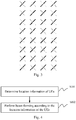
Fig.4 is a schematic flow chart of a beam-forming method according to an embodiment of the invention; -
Fig.5 is a schematic diagram of scheduling schemes of different clusters of UEs according to an embodiment of the invention; -
Fig.6 is a schematic structural diagram of a beam-forming apparatus according to an embodiment of the invention; and -
Fig.7 is a schematic structural diagram of another beam-forming apparatus according to an embodiment of the invention. - The embodiments of the invention provide a beam-forming method and apparatus, to perform beam-forming according to location information of UEs, so as to guarantee high coverage performance of a broadcast beam, and to avoid a significant loss of power arising from a too low amplitude of weight of broadcast beam-forming covering the entire coverage area of a cell.
- A flexible vertical coverage area can be provided with massive MIMO, but a design of a broadcast beam is closely related to a coverage scenario, it is very difficult to select an appropriate vertical beam width and downward-inclination angle precisely. The embodiments of the invention generally address the problem in a massive MIMO scenario that the performance of a control channel may be degraded due to a significant loss of a beam-forming factor of broadcast beam covering all the locations in a coverage area, so the embodiments of the invention provide how to select an appropriate weight of beam-forming according to the location distribution of UEs so as to guarantee high coverage performance.
- A flexible broadcast beam across frames is possible with massive MIMO, so in the embodiments of the invention, the location distribution of UEs can be statistically determined, and an appropriate broadcast beam-forming factor can be selected according to the characteristic of the location distribution of the UEs, so that the same weight of broadcast beam-forming can be selected for the UEs in the same location distribution, and the UEs in different 1 distributions can be distinguished in a time-division mode.
- Referring to
Fig.4 , a beam-forming method according to an embodiment of the invention includes the following steps. - The step S101 is to determine location information of UEs.
- The step S102 is to perform beam-forming according to the location information of the UEs.
- With this method, the location information of the UEs is determined, and beam-forming is performed according to the location information of the UEs, so that high coverage performance of the broadcast beam can be guaranteed, to thereby avoid a significant loss of power arising from a too low amplitude of the weight of broadcast beam-forming covering the entire area of a cell.
- Optionally before the location information of the UEs is determined, the method further includes: selecting an initial broadcast beam so that the UEs access a network using the initial broadcast beam.
- Optionally determining the location information of the UEs includes: making a statistics of Angles of Arrival (AOA) in the horizontal direction and Elevations of Arrival (EOA) of the UEs according to a Sounding Reference Signal (SRS).
- Optionally, for each UE, performing beam-forming according to the location information of the UE includes: determining a beam-forming factor in the horizontal direction of the broadcast beam according to the AOA of the UE; determining a beam-forming factor in the vertical direction of the broadcast beam according to the EOA of the UE; and determining a weight of broadcast beam-forming according to the beam-forming factor in the horizontal direction, and the beam-forming factor in the vertical direction.
- Optionally the method further includes: clustering a plurality of UEs; and scheduling the UEs in the same cluster using the same weight of broadcast beam-forming.
- Optionally the UEs in different clusters are scheduled using the same weight of broadcast beam-forming in a time-division mode at a preset periodicity.
- For example, a specific flow includes the following steps.
- The first step is to select an initial broadcast beam.
- The base station can select an initial broadcast beam, where both the horizontal width and the vertical width of the beam are large, and for example, the horizontal width is 65 degrees, and the vertical width is 30 degrees, to thereby guarantee a large coverage range for initial accesses of the UEs.
- The second step is to determine an AOA distribution in the horizontal direction, and an EOA distribution in the vertical direction of the UE(s).
- Specifically after the UE accesses the network, a statistics of the AOA distribution in the horizontal direction, and the EOA distribution in the vertical direction of the accessing UE is made according to a Sounding Reference Signal (SRS) while the UE is being served. For example, the AOA distribution in the horizontal direction of the UE lies between 0 to 30 degrees, and the EOA distribution in the vertical direction of the UE lies between 30 degrees to 60 degrees.
- The third step is to calculate a weight of broadcast beam-forming dynamically according to the AOA distribution and the EOA distribution of the UE.
- For example, if the AOA distribution in the horizontal direction of the UE lies between 0 to 30 degrees, then the AOA of the UE may be selected as 20 degrees; and if the EOA distribution in the horizontal direction of the UE lies between 30 degrees to 60 degrees, then the EOA of the UE may be selected as 50 degrees.
- After the AOA and the EOA are determined, a forming vector in the horizontal direction is calculated in the following steps.
- The step a is to calculate R=H'∗H from Sounding Reference Signal (SRS) information H on antennas in the horizontal direction, where R is a correlation matrix, and to perform Singular Value Decomposition (SVD) on R to obtain the largest eigenvalue vector.
- The step b is to calculate an eigenvector of the AOA as exp {1i·2π·sin(AOA) . (d 0 - d)}, where d is a preset spacing between adjacent antennas, d0 is a preset distance between any one of the antennas and the center of all the antennas, and both d and d0 are preset constants; and 1i in the equation represents a complex number, i.e., sqrt(-1), and the AOA in the equation is 20 degrees, for example.
- The step c is to correlate the eigenvector of the AOA with the largest eigenvalue vector to obtain an index corresponding to a largest AOA Specifically the two vectors are the mostly highly correlated with each other, and there is an eigenvector of each AOA index, where the two vectors are conjugated and multiplied with each other, and the largest product thereof is the index corresponding to the largest AOA.
- The step d is to determine the forming vector in the horizontal direction from the index, where each AOA corresponds to one eigenvector, as defined in the equation above of the eigenvector of the AOA.
- Alike the forming vector in the vertical direction can be determined from the EOA.
- The weight of broadcast beam-forming can be determined as the Kronecker product of the forming vector in the horizontal direction, and the forming vector in the vertical direction.
- For example, the directivity and the width of the broadcast beam (the values and the ranges of the AOA and the EOA) are determined according to the AOA and EOA distribution of the UE under some criterion, and vertical angles of the broadcast beam of 90% of the UEs are distributed in the angle range of 10 degrees to 20 degrees, so the direction of the main lobe of the broadcast beam can point at the central angle of the angle range, i.e., 15 degrees, and the vertical beam width of the broadcast beam is selected as 10 degrees; a corresponding weight in the vertical direction is generated accordingly, and alike a weight in the horizontal direction can be generated in the equation exp{1i·2π·sin(AOA)·(d 0-d)} of the AOA, where firstly the vector in the vertical direction, and the vector in the horizontal direction are generated respectively in the equation of the AOA, and then the weight of broadcast beam-forming is determined as their Kronecker product.
- It shall be noted that the AOA distribution in the horizontal direction, and the EOA distribution in the vertical direction of the UE are determined in the second step above so that the AOA value and the EOA value are calculated using an SRS, and specifically the eigenvector and the AOA vector are correlated, and the index of the angle when their correlation value is largest is determined.
- Furthermore there are AOA in the horizontal direction, and EOA in the vertical direction of UE due to 3D-MIMO, so the distributions of the AOA in the horizontal direction, and the EOA in the vertical direction are analyzed respectively, and it is determined whether the UEs can be clustered, that is, whether the UEs lie in some range. Whether the UEs can be clustered can be determined by determining whether the AOA distribution of the UEs lies in some angle range, e.g., the range of 0 to 30 degrees, and only when the UEs can be clustered, then the UEs can be assigned to a cluster; otherwise, the UEs cannot be assigned to any cluster.
- Optionally the UEs can be clustered (or grouped) under some criterion according to the AOA distributions and the EOA distributions of the UEs, and for example, the UEs with their AOAs distributed between 0 and 30 degrees are assigned to one cluster, and the UEs with their AOAs distributed between 30 degrees and 60 degrees are assigned to another cluster.
- There are the same angle (AOA and EOA) distributes of the UEs in the same cluster, where there are the same AOA distribution and the same EOA distribution thereof, so corresponding weights of broadcast beam-forming are generated according to the central angles and the angle widths of angle ranges of the respective clusters (that is, the weight of broadcast beam-forming is determined as the Kronecker product as described above).
- Since there are different weights of broadcast beam-forming for the UEs in different clusters, the UEs with the different weights of broadcast beam-forming can be scheduled in different sub-frames in a time-division mode. Since the UEs may perform channel estimation using preceding and succeeding downlink sub-frames, they can be scheduled in the time-division mode at a periodicity of 5ms, for example.
- By way of an example, a building covered with massive MIMO includes different floors with different angle distributions in different clusters, and UEs in the different clusters are scheduled at different instances of time, so that a cell can be virtually split vertically. Referring to
Fig.5 , D represents a downlink sub-frame, S represents a special sub-frame, and U represents an uplink sub-frame; and UEs in a cluster 1 are scheduled in four consecutive downlink sub-frames between the first two U, and UEs in a cluster 2 are scheduled in four consecutive downlink sub-frames between another two U. - In correspondence to the method above, referring to
Fig.6 , an embodiment of the invention provides a beam-forming apparatus including the followings. - A
first unit 11 is configured to determine location information of UEs. - A
second unit 12 is configured to perform beam-forming according to the location information of the UEs. - Optionally the first unit is further configured to select an initial broadcast beam so that the UEs access a network using the initial broadcast beam, before the location information of the UEs is determined.
- Optionally the first unit is configured: to make a statistics of Angles of Arrival (AOA) in the horizontal direction, and Elevations of Arrival (EOA) of the UEs according to a Sounding Reference Signal (SRS).
- Optionally the second unit is configured: to determine beam-forming factors in the horizontal direction of the broadcast beam according to the AOA of the UEs; to determine beam-forming factors in the vertical direction of the broadcast beam according to the EOA of the UEs; and to determine weights of broadcast beam-forming according to the beam-forming factors in the horizontal direction, and the beam-forming factors in the vertical direction.
- Optionally the second unit is further configured: to cluster the plurality of UEs are clustered; and to schedule the UEs in the same cluster using the same weight of broadcast beam-forming.
- Optionally the second unit is configured to schedule the UEs in different clusters in a time-division mode using the same weight of broadcast beam-forming at a preset periodicity.
- Either of the units above can be embodied as a processor.
- The beam-forming apparatus can be a base station at the network side, for example.
- Referring to
Fig.7 , an embodiment of the invention provides another beam-forming apparatus including the followings. - A
processor 500 is configured to read and execute program in a memory 502: to determine location information of UEs; and to perform beam-forming according to the location information of the UEs. - Optionally the
processor 500 is further configured to select an initial broadcast beam so that the UEs access a network using the initial broadcast beam, before the location information of the UEs is determined. - Optionally the
processor 500 configured to determine the location information of the UEs is configured: to make a statistics of Angles of Arrival (AOA) in the horizontal direction, and Elevations of Arrival (EOA) of the UE according to a Sounding Reference Signal (SRS). - Optionally the
processor 500 configured to perform beam-forming according to the location information of the UEs is configured: to determine beam-forming factors in the horizontal direction of the broadcast beam according to the AOA of the UEs; to determine forming factors in the vertical direction of the broadcast beam according to the EOA of the UEs; and to determine weights of broadcast beam-forming according to the beam-forming factors in the horizontal direction, and the beam-forming factors in the vertical direction. - Optionally the
processor 500 is further configured: to cluster the plurality of UEs; and to schedule the UEs in the same cluster using the same weight of broadcast beam-forming. - Optionally the
processor 500 is configured to schedule the UEs in different clusters in a time-division mode using the same weight of broadcast beam-forming at a preset periodicity. - A
transceiver 510 is configured to receive and transmit data under the control of theprocessor 500. Of course, thetransceiver 510 in this embodiment is optional but not necessary. - Here in
Fig.7 , the bus architecture can include any number of interconnecting buses and bridges to particularly link together various circuits including one or more processors represented by theprocessor 500, and one or more memories represented by thememory 520. The bus architecture can further link together various other circuits, e.g., a peripheral device, a manostat, a power management circuit, etc., all of which are well known in the art, so a further description thereof will be omitted in this context. The bus interface serves as an interface. Thetransceiver 510 can be a number of elements, e.g., a transmitter and a receiver, which are units for communication with various other devices over a transmission medium. Theprocessor 500 is responsible for managing the bus architecture and performing normal processes, and thememory 520 can store data for use by theprocessor 500 in performing the operations. - The
processor 500 can be a Central Processing Unit (CPU), an Application-Specific Integrated Circuit (ASIC), a Field-Programmable Gate Array (FPGA), or a Complex Programmable Logic Device (CPLD). - An embodiment of the invention provides a computer storage medium configured to store computer program instructions, to be executed by the apparatus above, including program for performing the beam-forming method above.
- The computer storage medium can be any computer accessible available medium or data storage device including but not limited to a magnetic memory (e.g., a floppy disk, a hard disk, a magnetic tape, a Magnetic-Optical (MO) disk, etc.), an optical memory (e.g., a CD, a DVD, a BD, an HVD, etc.), a semiconductor memory (e.g., an ROM, an EPROM, an EEPROM, a nonvolatile memory (NAND FLASH), a Solid State Disk (SSD), etc.), etc.
- In summary, in the embodiments of the invention, the beam weight is selected dynamically according to the real distribution characteristic of the UEs ,so that the main lobe of the broadcast beam points to the center of the coverage area including the UEs, and the beam width can cover the majority of the UEs; and when the distributed UEs do not lie in a cluster, the different clusters of UEs can be scheduled at different instances of time in a time-division mode, so that a cell can be virtually split vertically. Furthermore in order to enable the UEs to estimate their channels using preceding and succeeding sub-frames, they can be scheduled at a periodicity of 5ms while being spaced by an uplink sub-frame. In the embodiments of the invention, the appropriate vertical beam and downward-inclination angles (AOA, EOA) can be selected according to the location distribution of the UEs without substantially any loss of the weight of broadcast beam-forming to thereby guarantee high coverage performance, so as to avoid a significant loss of power arising from a too low amplitude of weight of broadcast beam-forming covering the entire coverage area of the cell, which would otherwise have hindered the UEs from perceiving the channels demodulated using a CRS, e.g., a PDCCH, a PCFICH, a PHICH, a PDSCH, etc., because the performance is degraded due to a significant loss of power arising from a too low amplitude of weight of a broadcast beam covering the entire coverage area of the cell. As compared with the prior art in which a uniform vector of broadcast beam-forming is selected as 30 degrees in the vertical direction, and 65 degrees in the horizontal direction without taking any location distribution of UEs into account, in the embodiments of the invention, a statistics of the location distribution of the UEs is made so that one broadcast beam is applied to the UEs lying between 0 and 30 degrees, and the other broadcast beam is applied to the UEs lying between 30 degrees and 60 degrees, and in this way, the beams are narrowed, and the energy thereof is concentrated to thereby guarantee high coverage performance of the broadcast beam, so as to avoid a significant loss of power arising from a too low amplitude of weight of broadcast beam-forming coveraging the entire coverage area of a cell.
- Those skilled in the art shall appreciate that the embodiments of the invention can be embodied as a method, a system or a computer program product. Therefore the invention can be embodied in the form of an all-hardware embodiment, an all-software embodiment or an embodiment of software and hardware in combination. Furthermore the invention can be embodied in the form of a computer program product embodied in one or more computer useable storage mediums (including but not limited to a disk memory, a CD-ROM, an optical memory, etc.) in which computer useable program codes are contained.
- The invention has been described in a flow chart and/or a block diagram of the method, the device (system) and the computer program product according to the embodiments of the invention. It shall be appreciated that respective flows and/or blocks in the flow chart and/or the block diagram and combinations of the flows and/or the blocks in the flow chart and/or the block diagram can be embodied in computer program instructions. These computer program instructions can be loaded onto a general-purpose computer, a specific-purpose computer, an embedded processor or a processor of another programmable data processing device to produce a machine so that the instructions executed on the computer or the processor of the other programmable data processing device create means for performing the functions specified in the flow(s) of the flow chart and/or the block(s) of the block diagram.
- These computer program instructions can also be stored into a computer readable memory capable of directing the computer or the other programmable data processing device to operate in a specific manner so that the instructions stored in the computer readable memory create an article of manufacture including instruction means which perform the functions specified in the flow(s) of the flow chart and/or the block(s) of the block diagram.
- These computer program instructions can also be loaded onto the computer or the other programmable data processing device so that a series of operational steps are performed on the computer or the other programmable data processing device to create a computer implemented process so that the instructions executed on the computer or the other programmable device provide steps for performing the functions specified in the flow(s) of the flow chart and/or the block(s) of the block diagram.
- Although the preferred embodiments of the invention have been described, those skilled in the art benefiting from the underlying inventive concept can make additional modifications and variations to these embodiments. Therefore the appended claims are intended to be construed as encompassing the preferred embodiments and all the modifications and variations coming into the scope of the invention.
- Evidently those skilled in the art can make various modifications and variations to the invention without departing from the spirit and scope of the invention. Thus the invention is also intended to encompass these modifications and variations thereto so long as the modifications and variations come into the scope of the claims appended to the invention and their equivalents.
Claims (14)
- A beam-forming method, comprising:determining location information of a plurality of UEs; andperforming beam-forming according to the location information of the UEs.
- The method according to claim 1, wherein before the location information of the UEs is determined, the method further comprises:
selecting an initial broadcast beam so that the UEs access a network using the initial broadcast beam. - The method according to claim 2, wherein the determining the location information of UEs comprises:
making a statistics of Angles of Arrival, AOA, in the horizontal direction, and Elevations of Arrival, EOA, of the UEs according to a Sounding Reference Signal, SRS. - The method according to claim 3, wherein performing beam-forming according to the location information of the UEs comprises:determining beam-forming factors in the horizontal direction of the broadcast beam according to the AOA of the UEs;determining beam-forming factors in the vertical direction of the broadcast beam according to the EOA of the UEs; anddetermining weights of broadcast beam-forming according to the beam-forming factors in the horizontal direction, and the beam-forming factors in the vertical direction.
- The method according to claim 1, further comprising:clustering the plurality of UEs; andscheduling the UEs in a same cluster using a same weight of broadcast beam-forming.
- The method according to claim 5, wherein the UEs in different clusters are scheduled in a time-division mode using the same weight of broadcast beam-forming at a preset periodicity.
- A beam-forming apparatus, comprising:a first unit configured to determine location information of a plurality of UEs; anda second unit configured to perform beam-forming according to the location information of the UEs.
- The apparatus according to claim 7, wherein the first unit is further configured to select an initial broadcast beam so that the UEs access a network using the initial broadcast beam, before the location information of the UEs is determined.
- The apparatus according to claim 8, wherein the first unit is configured:
to make a statistics of Angles of Arrival, AOA, in the horizontal direction, and Elevations of Arrival, EOA, of the UEs according to a Sounding Reference Signal, SRS. - The apparatus according to claim 9, wherein the second unit is configured:to determine beam-forming factors in the horizontal direction of the broadcast beam according to the AOA of the UEs;to determine beam-forming factors in the vertical direction of the broadcast beam according to the EOA of the UEs; andto determine weights of broadcast beam-forming according to the beam-forming factors in the horizontal direction, and the beam-forming factors in the vertical direction.
- The apparatus according to claim 7, wherein the second unit is further configured:to cluster the plurality of UEs; andto schedule the UEs in a same cluster using a same weight of broadcast beam-forming.
- The apparatus according to claim 11, wherein the second unit is configured to schedule the UEs in different clusters in a time-division mode using the same weight of broadcast beam-forming at a preset periodicity.
- A beam-forming apparatus, comprising: a processor and a memory, wherein the processor is configured to read and execute program in the memory to perform the method according to any one of claims 1 to 6.
- A computer storage medium, comprising computer executable instructions configured to cause a computer to perform the method according to any one of claims 1 to 6.
Applications Claiming Priority (2)
| Application Number | Priority Date | Filing Date | Title |
|---|---|---|---|
| CN201610881732.5A CN107919896B (en) | 2016-10-09 | 2016-10-09 | Beam forming method and device |
| PCT/CN2017/098308 WO2018064920A1 (en) | 2016-10-09 | 2017-08-21 | Method and device for beamforming |
Publications (3)
| Publication Number | Publication Date |
|---|---|
| EP3525361A1 true EP3525361A1 (en) | 2019-08-14 |
| EP3525361A4 EP3525361A4 (en) | 2019-08-28 |
| EP3525361B1 EP3525361B1 (en) | 2025-03-12 |
Family
ID=61831633
Family Applications (1)
| Application Number | Title | Priority Date | Filing Date |
|---|---|---|---|
| EP17857801.9A Active EP3525361B1 (en) | 2016-10-09 | 2017-08-21 | Method and device for beamforming |
Country Status (4)
| Country | Link |
|---|---|
| US (1) | US10686507B2 (en) |
| EP (1) | EP3525361B1 (en) |
| CN (1) | CN107919896B (en) |
| WO (1) | WO2018064920A1 (en) |
Cited By (1)
| Publication number | Priority date | Publication date | Assignee | Title |
|---|---|---|---|---|
| EP3799325A1 (en) * | 2019-09-26 | 2021-03-31 | Telefonica, S.A. | Method and device for generating broadcast beams in massive mimo systems |
Families Citing this family (10)
| Publication number | Priority date | Publication date | Assignee | Title |
|---|---|---|---|---|
| WO2019080119A1 (en) * | 2017-10-27 | 2019-05-02 | 华为技术有限公司 | Method and apparatus for adjusting broadcast beam domains |
| CN112385151B (en) * | 2018-07-10 | 2022-07-29 | 华为技术有限公司 | Beam forming method and device, base station and storage medium |
| CN113271549B (en) * | 2020-02-17 | 2024-04-30 | 中兴通讯股份有限公司 | Method and device for sending weights, storage medium and electronic device |
| JP7011682B2 (en) * | 2020-06-08 | 2022-01-27 | Kddi株式会社 | Control devices, control methods, and programs that improve the utilization efficiency of Massive MIMO. |
| WO2022034692A1 (en) * | 2020-08-14 | 2022-02-17 | 日本電信電話株式会社 | Beam forming predicting device, method, and program |
| CN112351439B (en) * | 2020-10-28 | 2021-06-22 | 上海擎昆信息科技有限公司 | SSB broadcast beam optimization method and system |
| CN115441910A (en) * | 2021-06-01 | 2022-12-06 | 中兴通讯股份有限公司 | Antenna, antenna control method, and storage medium |
| CN114884548B (en) * | 2022-03-31 | 2025-08-29 | 上海瀚讯信息技术股份有限公司 | Self-adaptive beam tracking method |
| CN115243195B (en) * | 2022-07-20 | 2024-12-03 | 中国电信股份有限公司 | Broadcast beam realization method, base station, storage medium and communication equipment |
| EP4415277A1 (en) | 2023-01-25 | 2024-08-14 | Nokia Solutions and Networks Oy | Selection of set of analog beamforming weights for hybrid beamforming within wireless networks |
Family Cites Families (15)
| Publication number | Priority date | Publication date | Assignee | Title |
|---|---|---|---|---|
| US6232918B1 (en) * | 1997-01-08 | 2001-05-15 | Us Wireless Corporation | Antenna array calibration in wireless communication systems |
| US5852630A (en) * | 1997-07-17 | 1998-12-22 | Globespan Semiconductor, Inc. | Method and apparatus for a RADSL transceiver warm start activation procedure with precoding |
| DE10004000A1 (en) * | 2000-01-29 | 2001-08-02 | Bosch Gmbh Robert | Mobile communication system |
| KR101836207B1 (en) * | 2011-09-02 | 2018-04-19 | 엘지이노텍 주식회사 | Device and method for beamforming of antenna |
| CA2858171C (en) * | 2011-12-15 | 2017-12-05 | Intel Corporation | Use of location information in multi-radio devices for mmwave beamforming |
| KR102109655B1 (en) * | 2012-02-23 | 2020-05-12 | 한국전자통신연구원 | Method for multi-input multi-output communication in a large-scale antenna system |
| US9100146B2 (en) * | 2012-03-08 | 2015-08-04 | Alcatel Lucent | Virtual sectorization using an active anntenna array |
| WO2014139174A1 (en) * | 2013-03-15 | 2014-09-18 | Qualcomm Incorporated | Improved random access procedure with beamforming in lte |
| US9755797B2 (en) * | 2013-12-26 | 2017-09-05 | Mediatek Singapore Pte. Ltd. | Localization-based beamforming scheme for systems with multiple antennas |
| US10555309B2 (en) * | 2014-07-17 | 2020-02-04 | Lg Electronics Inc. | Method and device for transmitting downlink signal in wireless communication system |
| CN104779986B (en) * | 2015-04-07 | 2018-07-17 | 西安交通大学 | Using disturbance coordination method between the multiple cell of three-dimensional wave beam forming in 3D-MIMO systems |
| CN105099534A (en) * | 2015-08-22 | 2015-11-25 | 西安电子科技大学 | Positioning information assistance-based massive multi-input multi-output beamforming method |
| US9769828B2 (en) * | 2015-11-10 | 2017-09-19 | Fortinet, Inc. | Optimization of MU-MIMO beamforming in a wi-fi communication network based on mobility profiles |
| CN105634578A (en) * | 2015-12-29 | 2016-06-01 | 九派逐浪(北京)网络通讯技术股份有限公司 | Beam forming device, intelligent antenna and wireless communication equipment |
| CN108886389B (en) * | 2016-04-06 | 2020-10-27 | 华为技术有限公司 | Method and apparatus for transmitting control information in wireless communication network |
-
2016
- 2016-10-09 CN CN201610881732.5A patent/CN107919896B/en active Active
-
2017
- 2017-08-21 US US16/340,684 patent/US10686507B2/en active Active
- 2017-08-21 WO PCT/CN2017/098308 patent/WO2018064920A1/en not_active Ceased
- 2017-08-21 EP EP17857801.9A patent/EP3525361B1/en active Active
Cited By (2)
| Publication number | Priority date | Publication date | Assignee | Title |
|---|---|---|---|---|
| EP3799325A1 (en) * | 2019-09-26 | 2021-03-31 | Telefonica, S.A. | Method and device for generating broadcast beams in massive mimo systems |
| US11038562B2 (en) | 2019-09-26 | 2021-06-15 | Telefónica, S.A. | Method and device for generating broadcast beams in massive MIMO systems |
Also Published As
| Publication number | Publication date |
|---|---|
| WO2018064920A1 (en) | 2018-04-12 |
| CN107919896B (en) | 2020-05-05 |
| US10686507B2 (en) | 2020-06-16 |
| CN107919896A (en) | 2018-04-17 |
| EP3525361B1 (en) | 2025-03-12 |
| EP3525361A4 (en) | 2019-08-28 |
| US20190296813A1 (en) | 2019-09-26 |
Similar Documents
| Publication | Publication Date | Title |
|---|---|---|
| US10686507B2 (en) | Method and device for beamforming | |
| EP3140921B1 (en) | Beam forming using an antenna arrangement | |
| US9960828B2 (en) | Beam forming using an antenna arrangement | |
| EP4030636A2 (en) | Beamforming of beams | |
| EP3110033B1 (en) | Dual-stream beamforming method and device | |
| EP3522583A1 (en) | Antenna beam management method and related device | |
| EP2975778A1 (en) | Method and device for reporting channel state information in wireless communication system | |
| US11638256B2 (en) | Method and system for performing beam sweeping using multiple polarization | |
| US10848220B2 (en) | Compressing and decompressing beamspace coefficients | |
| EP4708720A2 (en) | Methods of csi-rs beamforming in angle-delay domains for type ii port selection codebook | |
| KR101290918B1 (en) | Communication system for using interference alignment scheme in multicell environment | |
| US12028147B2 (en) | Method and network node for uplink beam management | |
| US9450654B2 (en) | Multi-user multiple input multiple output (MIMO) communication with distributed antenna systems in wireless networks | |
| US9325401B2 (en) | Beamforming from multiple transmission sites | |
| JP7189336B2 (en) | Interference reduction method in communication device | |
| WO2024020951A1 (en) | Beamforming scheme | |
| US11043996B2 (en) | Managing transmission of a cell-specific reference signal | |
| KR102363565B1 (en) | Apparatus and method for transmitting and receiving reference signal in a wireless communication system using mimo and system thereof | |
| US12244376B2 (en) | Beamforming scheme in higher rank transmission | |
| GB2642881A (en) | Beam quality metric based on Gram matrix | |
| US20230269677A1 (en) | Beam pattern management for controlling radiated power levels and spatial priority | |
| WO2024175168A1 (en) | Method, network node, and computer program for downlink interference suppression in an access network |
Legal Events
| Date | Code | Title | Description |
|---|---|---|---|
| STAA | Information on the status of an ep patent application or granted ep patent |
Free format text: STATUS: THE INTERNATIONAL PUBLICATION HAS BEEN MADE |
|
| PUAI | Public reference made under article 153(3) epc to a published international application that has entered the european phase |
Free format text: ORIGINAL CODE: 0009012 |
|
| STAA | Information on the status of an ep patent application or granted ep patent |
Free format text: STATUS: REQUEST FOR EXAMINATION WAS MADE |
|
| 17P | Request for examination filed |
Effective date: 20190417 |
|
| AK | Designated contracting states |
Kind code of ref document: A1 Designated state(s): AL AT BE BG CH CY CZ DE DK EE ES FI FR GB GR HR HU IE IS IT LI LT LU LV MC MK MT NL NO PL PT RO RS SE SI SK SM TR |
|
| AX | Request for extension of the european patent |
Extension state: BA ME |
|
| A4 | Supplementary search report drawn up and despatched |
Effective date: 20190731 |
|
| RIC1 | Information provided on ipc code assigned before grant |
Ipc: H04B 7/0456 20170101ALI20190725BHEP Ipc: H04L 25/02 20060101ALI20190725BHEP Ipc: H04B 7/06 20060101AFI20190725BHEP Ipc: H04B 7/08 20060101ALI20190725BHEP Ipc: H04W 16/28 20090101ALI20190725BHEP |
|
| DAV | Request for validation of the european patent (deleted) | ||
| DAX | Request for extension of the european patent (deleted) | ||
| STAA | Information on the status of an ep patent application or granted ep patent |
Free format text: STATUS: EXAMINATION IS IN PROGRESS |
|
| 17Q | First examination report despatched |
Effective date: 20201113 |
|
| GRAP | Despatch of communication of intention to grant a patent |
Free format text: ORIGINAL CODE: EPIDOSNIGR1 |
|
| STAA | Information on the status of an ep patent application or granted ep patent |
Free format text: STATUS: GRANT OF PATENT IS INTENDED |
|
| INTG | Intention to grant announced |
Effective date: 20241118 |
|
| GRAS | Grant fee paid |
Free format text: ORIGINAL CODE: EPIDOSNIGR3 |
|
| GRAA | (expected) grant |
Free format text: ORIGINAL CODE: 0009210 |
|
| STAA | Information on the status of an ep patent application or granted ep patent |
Free format text: STATUS: THE PATENT HAS BEEN GRANTED |
|
| AK | Designated contracting states |
Kind code of ref document: B1 Designated state(s): AL AT BE BG CH CY CZ DE DK EE ES FI FR GB GR HR HU IE IS IT LI LT LU LV MC MK MT NL NO PL PT RO RS SE SI SK SM TR |
|
| REG | Reference to a national code |
Ref country code: GB Ref legal event code: FG4D |
|
| REG | Reference to a national code |
Ref country code: CH Ref legal event code: EP |
|
| REG | Reference to a national code |
Ref country code: DE Ref legal event code: R096 Ref document number: 602017088333 Country of ref document: DE |
|
| REG | Reference to a national code |
Ref country code: IE Ref legal event code: FG4D |
|
| PG25 | Lapsed in a contracting state [announced via postgrant information from national office to epo] |
Ref country code: RS Free format text: LAPSE BECAUSE OF FAILURE TO SUBMIT A TRANSLATION OF THE DESCRIPTION OR TO PAY THE FEE WITHIN THE PRESCRIBED TIME-LIMIT Effective date: 20250612 |
|
| PG25 | Lapsed in a contracting state [announced via postgrant information from national office to epo] |
Ref country code: FI Free format text: LAPSE BECAUSE OF FAILURE TO SUBMIT A TRANSLATION OF THE DESCRIPTION OR TO PAY THE FEE WITHIN THE PRESCRIBED TIME-LIMIT Effective date: 20250312 |
|
| PG25 | Lapsed in a contracting state [announced via postgrant information from national office to epo] |
Ref country code: ES Free format text: LAPSE BECAUSE OF FAILURE TO SUBMIT A TRANSLATION OF THE DESCRIPTION OR TO PAY THE FEE WITHIN THE PRESCRIBED TIME-LIMIT Effective date: 20250312 |
|
| REG | Reference to a national code |
Ref country code: LT Ref legal event code: MG9D |
|
| PG25 | Lapsed in a contracting state [announced via postgrant information from national office to epo] |
Ref country code: NO Free format text: LAPSE BECAUSE OF FAILURE TO SUBMIT A TRANSLATION OF THE DESCRIPTION OR TO PAY THE FEE WITHIN THE PRESCRIBED TIME-LIMIT Effective date: 20250612 |
|
| PG25 | Lapsed in a contracting state [announced via postgrant information from national office to epo] |
Ref country code: HR Free format text: LAPSE BECAUSE OF FAILURE TO SUBMIT A TRANSLATION OF THE DESCRIPTION OR TO PAY THE FEE WITHIN THE PRESCRIBED TIME-LIMIT Effective date: 20250312 |
|
| REG | Reference to a national code |
Ref country code: NL Ref legal event code: MP Effective date: 20250312 |
|
| PG25 | Lapsed in a contracting state [announced via postgrant information from national office to epo] |
Ref country code: LV Free format text: LAPSE BECAUSE OF FAILURE TO SUBMIT A TRANSLATION OF THE DESCRIPTION OR TO PAY THE FEE WITHIN THE PRESCRIBED TIME-LIMIT Effective date: 20250312 |
|
| PG25 | Lapsed in a contracting state [announced via postgrant information from national office to epo] |
Ref country code: GR Free format text: LAPSE BECAUSE OF FAILURE TO SUBMIT A TRANSLATION OF THE DESCRIPTION OR TO PAY THE FEE WITHIN THE PRESCRIBED TIME-LIMIT Effective date: 20250613 Ref country code: BG Free format text: LAPSE BECAUSE OF FAILURE TO SUBMIT A TRANSLATION OF THE DESCRIPTION OR TO PAY THE FEE WITHIN THE PRESCRIBED TIME-LIMIT Effective date: 20250312 |
|
| REG | Reference to a national code |
Ref country code: AT Ref legal event code: MK05 Ref document number: 1775904 Country of ref document: AT Kind code of ref document: T Effective date: 20250312 |
|
| PG25 | Lapsed in a contracting state [announced via postgrant information from national office to epo] |
Ref country code: NL Free format text: LAPSE BECAUSE OF FAILURE TO SUBMIT A TRANSLATION OF THE DESCRIPTION OR TO PAY THE FEE WITHIN THE PRESCRIBED TIME-LIMIT Effective date: 20250312 |
|
| PG25 | Lapsed in a contracting state [announced via postgrant information from national office to epo] |
Ref country code: SE Free format text: LAPSE BECAUSE OF FAILURE TO SUBMIT A TRANSLATION OF THE DESCRIPTION OR TO PAY THE FEE WITHIN THE PRESCRIBED TIME-LIMIT Effective date: 20250312 |
|
| PG25 | Lapsed in a contracting state [announced via postgrant information from national office to epo] |
Ref country code: SM Free format text: LAPSE BECAUSE OF FAILURE TO SUBMIT A TRANSLATION OF THE DESCRIPTION OR TO PAY THE FEE WITHIN THE PRESCRIBED TIME-LIMIT Effective date: 20250312 |
|
| PG25 | Lapsed in a contracting state [announced via postgrant information from national office to epo] |
Ref country code: PT Free format text: LAPSE BECAUSE OF FAILURE TO SUBMIT A TRANSLATION OF THE DESCRIPTION OR TO PAY THE FEE WITHIN THE PRESCRIBED TIME-LIMIT Effective date: 20250714 |
|
| PGFP | Annual fee paid to national office [announced via postgrant information from national office to epo] |
Ref country code: DE Payment date: 20250820 Year of fee payment: 9 |
|
| PG25 | Lapsed in a contracting state [announced via postgrant information from national office to epo] |
Ref country code: PL Free format text: LAPSE BECAUSE OF FAILURE TO SUBMIT A TRANSLATION OF THE DESCRIPTION OR TO PAY THE FEE WITHIN THE PRESCRIBED TIME-LIMIT Effective date: 20250312 Ref country code: IT Free format text: LAPSE BECAUSE OF FAILURE TO SUBMIT A TRANSLATION OF THE DESCRIPTION OR TO PAY THE FEE WITHIN THE PRESCRIBED TIME-LIMIT Effective date: 20250312 |
|
| PGFP | Annual fee paid to national office [announced via postgrant information from national office to epo] |
Ref country code: GB Payment date: 20250820 Year of fee payment: 9 |
|
| PG25 | Lapsed in a contracting state [announced via postgrant information from national office to epo] |
Ref country code: AT Free format text: LAPSE BECAUSE OF FAILURE TO SUBMIT A TRANSLATION OF THE DESCRIPTION OR TO PAY THE FEE WITHIN THE PRESCRIBED TIME-LIMIT Effective date: 20250312 |
|
| PGFP | Annual fee paid to national office [announced via postgrant information from national office to epo] |
Ref country code: FR Payment date: 20250828 Year of fee payment: 9 |
|
| PG25 | Lapsed in a contracting state [announced via postgrant information from national office to epo] |
Ref country code: EE Free format text: LAPSE BECAUSE OF FAILURE TO SUBMIT A TRANSLATION OF THE DESCRIPTION OR TO PAY THE FEE WITHIN THE PRESCRIBED TIME-LIMIT Effective date: 20250312 Ref country code: CZ Free format text: LAPSE BECAUSE OF FAILURE TO SUBMIT A TRANSLATION OF THE DESCRIPTION OR TO PAY THE FEE WITHIN THE PRESCRIBED TIME-LIMIT Effective date: 20250312 |
|
| PG25 | Lapsed in a contracting state [announced via postgrant information from national office to epo] |
Ref country code: RO Free format text: LAPSE BECAUSE OF FAILURE TO SUBMIT A TRANSLATION OF THE DESCRIPTION OR TO PAY THE FEE WITHIN THE PRESCRIBED TIME-LIMIT Effective date: 20250312 |
|
| PG25 | Lapsed in a contracting state [announced via postgrant information from national office to epo] |
Ref country code: SK Free format text: LAPSE BECAUSE OF FAILURE TO SUBMIT A TRANSLATION OF THE DESCRIPTION OR TO PAY THE FEE WITHIN THE PRESCRIBED TIME-LIMIT Effective date: 20250312 |
|
| PG25 | Lapsed in a contracting state [announced via postgrant information from national office to epo] |
Ref country code: IS Free format text: LAPSE BECAUSE OF FAILURE TO SUBMIT A TRANSLATION OF THE DESCRIPTION OR TO PAY THE FEE WITHIN THE PRESCRIBED TIME-LIMIT Effective date: 20250712 |
|
| REG | Reference to a national code |
Ref country code: DE Ref legal event code: R097 Ref document number: 602017088333 Country of ref document: DE |
|
| PG25 | Lapsed in a contracting state [announced via postgrant information from national office to epo] |
Ref country code: DK Free format text: LAPSE BECAUSE OF FAILURE TO SUBMIT A TRANSLATION OF THE DESCRIPTION OR TO PAY THE FEE WITHIN THE PRESCRIBED TIME-LIMIT Effective date: 20250312 |
|
| PLBE | No opposition filed within time limit |
Free format text: ORIGINAL CODE: 0009261 |
|
| STAA | Information on the status of an ep patent application or granted ep patent |
Free format text: STATUS: NO OPPOSITION FILED WITHIN TIME LIMIT |
|
| REG | Reference to a national code |
Ref country code: CH Ref legal event code: L10 Free format text: ST27 STATUS EVENT CODE: U-0-0-L10-L00 (AS PROVIDED BY THE NATIONAL OFFICE) Effective date: 20260121 |
|
| 26N | No opposition filed |
Effective date: 20251215 |
|
| REG | Reference to a national code |
Ref country code: CH Ref legal event code: H13 Free format text: ST27 STATUS EVENT CODE: U-0-0-H10-H13 (AS PROVIDED BY THE NATIONAL OFFICE) Effective date: 20260324 |
|
| PG25 | Lapsed in a contracting state [announced via postgrant information from national office to epo] |
Ref country code: MC Free format text: LAPSE BECAUSE OF FAILURE TO SUBMIT A TRANSLATION OF THE DESCRIPTION OR TO PAY THE FEE WITHIN THE PRESCRIBED TIME-LIMIT Effective date: 20250312 |
|
| PG25 | Lapsed in a contracting state [announced via postgrant information from national office to epo] |
Ref country code: LU Free format text: LAPSE BECAUSE OF NON-PAYMENT OF DUE FEES Effective date: 20250821 |
|
| PG25 | Lapsed in a contracting state [announced via postgrant information from national office to epo] |
Ref country code: CH Free format text: LAPSE BECAUSE OF NON-PAYMENT OF DUE FEES Effective date: 20250831 |