EP3525283A1 - Antenna device and reading system - Google Patents
Antenna device and reading system Download PDFInfo
- Publication number
- EP3525283A1 EP3525283A1 EP19156872.4A EP19156872A EP3525283A1 EP 3525283 A1 EP3525283 A1 EP 3525283A1 EP 19156872 A EP19156872 A EP 19156872A EP 3525283 A1 EP3525283 A1 EP 3525283A1
- Authority
- EP
- European Patent Office
- Prior art keywords
- antenna element
- reading apparatus
- reading
- wireless tag
- antenna
- Prior art date
- Legal status (The legal status is an assumption and is not a legal conclusion. Google has not performed a legal analysis and makes no representation as to the accuracy of the status listed.)
- Granted
Links
Images




Classifications
-
- G—PHYSICS
- G06—COMPUTING OR CALCULATING; COUNTING
- G06K—GRAPHICAL DATA READING; PRESENTATION OF DATA; RECORD CARRIERS; HANDLING RECORD CARRIERS
- G06K7/00—Methods or arrangements for sensing record carriers, e.g. for reading patterns
- G06K7/10—Methods or arrangements for sensing record carriers, e.g. for reading patterns by electromagnetic radiation, e.g. optical sensing; by corpuscular radiation
- G06K7/10009—Methods or arrangements for sensing record carriers, e.g. for reading patterns by electromagnetic radiation, e.g. optical sensing; by corpuscular radiation sensing by radiation using wavelengths larger than 0.1 mm, e.g. radio-waves or microwaves
- G06K7/10316—Methods or arrangements for sensing record carriers, e.g. for reading patterns by electromagnetic radiation, e.g. optical sensing; by corpuscular radiation sensing by radiation using wavelengths larger than 0.1 mm, e.g. radio-waves or microwaves using at least one antenna particularly designed for interrogating the wireless record carriers
-
- G—PHYSICS
- G06—COMPUTING OR CALCULATING; COUNTING
- G06K—GRAPHICAL DATA READING; PRESENTATION OF DATA; RECORD CARRIERS; HANDLING RECORD CARRIERS
- G06K7/00—Methods or arrangements for sensing record carriers, e.g. for reading patterns
- G06K7/10—Methods or arrangements for sensing record carriers, e.g. for reading patterns by electromagnetic radiation, e.g. optical sensing; by corpuscular radiation
- G06K7/10009—Methods or arrangements for sensing record carriers, e.g. for reading patterns by electromagnetic radiation, e.g. optical sensing; by corpuscular radiation sensing by radiation using wavelengths larger than 0.1 mm, e.g. radio-waves or microwaves
- G06K7/10297—Methods or arrangements for sensing record carriers, e.g. for reading patterns by electromagnetic radiation, e.g. optical sensing; by corpuscular radiation sensing by radiation using wavelengths larger than 0.1 mm, e.g. radio-waves or microwaves arrangements for handling protocols designed for non-contact record carriers such as RFIDs NFCs, e.g. ISO/IEC 14443 and 18092
-
- G—PHYSICS
- G06—COMPUTING OR CALCULATING; COUNTING
- G06K—GRAPHICAL DATA READING; PRESENTATION OF DATA; RECORD CARRIERS; HANDLING RECORD CARRIERS
- G06K7/00—Methods or arrangements for sensing record carriers, e.g. for reading patterns
- G06K7/0004—Hybrid readers
-
- H—ELECTRICITY
- H01—ELECTRIC ELEMENTS
- H01Q—ANTENNAS, i.e. RADIO AERIALS
- H01Q1/00—Details of, or arrangements associated with, antennas
- H01Q1/12—Supports; Mounting means
- H01Q1/14—Supports; Mounting means for wire or other non-rigid radiating elements
-
- H—ELECTRICITY
- H01—ELECTRIC ELEMENTS
- H01Q—ANTENNAS, i.e. RADIO AERIALS
- H01Q1/00—Details of, or arrangements associated with, antennas
- H01Q1/12—Supports; Mounting means
- H01Q1/22—Supports; Mounting means by structural association with other equipment or articles
- H01Q1/2208—Supports; Mounting means by structural association with other equipment or articles associated with components used in interrogation type services, i.e. in systems for information exchange between an interrogator/reader and a tag/transponder, e.g. in Radio Frequency Identification [RFID] systems
- H01Q1/2216—Supports; Mounting means by structural association with other equipment or articles associated with components used in interrogation type services, i.e. in systems for information exchange between an interrogator/reader and a tag/transponder, e.g. in Radio Frequency Identification [RFID] systems used in interrogator/reader equipment
-
- H—ELECTRICITY
- H01—ELECTRIC ELEMENTS
- H01Q—ANTENNAS, i.e. RADIO AERIALS
- H01Q19/00—Combinations of primary active antenna elements and units with secondary devices, e.g. with quasi-optical devices, for giving the antenna a desired directional characteristic
- H01Q19/10—Combinations of primary active antenna elements and units with secondary devices, e.g. with quasi-optical devices, for giving the antenna a desired directional characteristic using reflecting surfaces
- H01Q19/106—Combinations of primary active antenna elements and units with secondary devices, e.g. with quasi-optical devices, for giving the antenna a desired directional characteristic using reflecting surfaces using two or more intersecting plane surfaces, e.g. corner reflector antennas
-
- G—PHYSICS
- G06—COMPUTING OR CALCULATING; COUNTING
- G06K—GRAPHICAL DATA READING; PRESENTATION OF DATA; RECORD CARRIERS; HANDLING RECORD CARRIERS
- G06K19/00—Record carriers for use with machines and with at least a part designed to carry digital markings
- G06K19/06—Record carriers for use with machines and with at least a part designed to carry digital markings characterised by the kind of the digital marking, e.g. shape, nature, code
- G06K19/067—Record carriers with conductive marks, printed circuits or semiconductor circuit elements, e.g. credit or identity cards also with resonating or responding marks without active components
- G06K19/07—Record carriers with conductive marks, printed circuits or semiconductor circuit elements, e.g. credit or identity cards also with resonating or responding marks without active components with integrated circuit chips
- G06K19/0723—Record carriers with conductive marks, printed circuits or semiconductor circuit elements, e.g. credit or identity cards also with resonating or responding marks without active components with integrated circuit chips the record carrier comprising an arrangement for non-contact communication, e.g. wireless communication circuits on transponder cards, non-contact smart cards or RFIDs
Definitions
- Embodiments described herein relate generally to an antenna device and a reading system.
- a wireless tag reading apparatus that reads and writes information from and into a wireless tag, such as a radio frequency identification (RFID) tag, an electronic tag, and a transponder.
- RFID radio frequency identification
- the wireless tag is embedded in a portable article, such as a card and a smartphone.
- a connection is established and information is exchanged therebetween.
- One of the objects of the present invention is to improve prior art techniques and overcome at least some of the prior art problems as for instance above illustrated.
- an antenna device of a reading apparatus configured to read a wireless tag, the device comprising: a housing; an antenna element bent and extending in first and second directions within the housing; a first conductor that covers a bottom surface of the antenna element; and a second conductor that covers one or more of side surfaces of the antenna element on a major angle side thereof.
- the antenna element is bent at a right angle and the major angle is 270 degrees.
- the device according to the first aspect of the invention further comprises a branching circuit, wherein the antenna element comprises first and second portions extending in the first and second directions, respectively, and the branching circuit is configured to output an analog signal to each of the first and second portions.
- the branching circuit outputs the signal in response to a signal transmitted from a transmitter of the reading apparatus.
- the branching circuit outputs a signal to a receiver of the reading apparatus when a signal from the wireless tag is received by the antenna element.
- the housing has a rectangular shape, and the first and second directions are parallel to two adjacent side surfaces of the housing.
- the antenna element is a substrate antenna formed on a substrate within the housing.
- the housing has an opening partially surrounded by the antenna element.
- the opening has a rectangular shape.
- the wireless tag is an RFID tag.
- a reading system comprising a first reading apparatus configured to read a symbol code by using a laser beam; and a second reading apparatus configured to read a wireless tag and comprising: a housing, an antenna element bent and extending in first and second directions within the housing, a first conductor that covers a bottom surface of the antenna element, and a second conductor that covers one or more of side surfaces of the antenna element on a major angle side thereof.
- the housing of the second reading apparatus has an opening, and the first reading apparatus is located in the opening.
- the symbol code and the wireless tag are printed and attached to an article sold in a grocery store.
- the antenna element is bent at a right angle and the major angle is 270 degrees.
- the second reading apparatus comprises a branching circuit
- the antenna elements comprise first and second portions extending in the first and second directions
- the branching circuit is configured to output an analog signal to each of the first and second portions.
- the second reading apparatus comprises a transmitter, and the branching circuit outputs the signal in response to a signal transmitted from the transmitter.
- the second reading apparatus comprises a receiver, and the branching circuit outputs a signal to the receiver when a signal from the wireless tag is received by the antenna element.
- the housing has a rectangular shape, and the first and second directions are parallel to two adjacent side surfaces of the housing.
- the antenna element is a substrate antenna formed on a substrate within the housing.
- the housing has an opening partially surrounded by the antenna element.
- the opening has a rectangular shape.
- One or more embodiments provide an antenna device and a reading system capable of reducing deterioration of radiation characteristics of radio waves.
- an antenna device of a reading apparatus configured to read a wireless tag.
- the antenna device includes a housing, an antenna element bent and extending in first and second directions within the housing, a first conductor that covers a bottom surface of the antenna element, and a second conductor that covers one or more of side surfaces of the antenna element on a major angle side thereof.
- Embodiments of an antenna device and a reading system will be described in detail below with reference to the accompanying drawings.
- the embodiments to be described below are directed to the antenna device and the reading system but are not limited to the described configuration, specifications, and the like thereof.
- the antenna and the reading system of one of the embodiments are applied to a point of sales (POS) terminal connected to an antenna that transmits and receives radio waves to and from a wireless tag at a store such as a supermarket and the like.
- POS point of sales
- FIG. 1 is a diagram showing a reading system 1 according to the present embodiment.
- the reading system 1 includes a POS terminal 10, a code symbol reading apparatus 20, and a wireless tag reading apparatus 30.
- the POS terminal 10 is communicably connected to the code symbol reading apparatus 20 and the wireless tag reading apparatus 30.
- the reading system 1 reads a code symbol 41 included in an article 4 or a wireless tag 42 included in an article 4 by each apparatus.
- the POS terminal 10 is an information processing apparatus that executes sales registration for registering commodities to be sold and checkout processing of commodities registered through sales registration.
- the POS terminal 10 requests the code symbol reading apparatus 20 and the wireless tag reading apparatus 30 to execute reading processing of a reading target. Then, the POS terminal 10 receives the execution result of the reading processing from the code symbol reading apparatus 20 and the wireless tag reading apparatus 30.
- the code symbol reading apparatus 20 is a reading apparatus that reads the code symbol 41 such as a bar code, a two-dimensional code, and the like.
- the code symbol reading apparatus 20 reads the code symbol 41 with reflected light by, for example, radiating a laser beam.
- the code symbol reading apparatus 20 executes reading processing when receiving a request to execute reading processing from the POS terminal 10. Then, the code symbol reading apparatus 20 transmits the reading result by the reading processing to the POS terminal 10.
- the wireless tag reading apparatus 30 is a reading apparatus that executes reading and writing of various kinds of information to and from the wireless tag 42 by executing wireless communication with the wireless tag 42 called a radio frequency identification (RFID) tag, an electronic tag, or a responder.
- RFID radio frequency identification
- the wireless tag reading apparatus 30 receives a request to execute the reading processing from the POS terminal 10, the wireless tag reading apparatus 30 transmits a radio wave for reading the wireless tag 42.
- the wireless tag reading apparatus 30 receives various kinds of information stored in the wireless tag 42 from the wireless tag 42. In this manner, the wireless tag reading apparatus 30 executes the reading processing. Then, the wireless tag reading apparatus 30 transmits the reading result by the reading processing to the POS terminal 10.
- FIG. 2 is a perspective view showing an example of the antenna 31.
- the antenna 31 includes a rectangular housing 311 having a hollow portion 312.
- the code symbol reading apparatus 20 is disposed in the hollow portion 312.
- the code symbol reading apparatus 20 radiates a laser beam for reading the code symbol 41, for example, toward the front surface or the left side surface in FIG. 2 .
- the hollow portion 312 shown in FIG. 2 has a rectangular shape, but may have a circular shape or may have a shape conformed to the shape of the code symbol reading apparatus 20.
- the antenna 31 includes an antenna element 313 branching into two directions inside the housing 311.
- the antenna element 313 is, for example, a substrate antenna formed on a substrate.
- the antenna element 313 extending in an X direction shown in FIG. 2 will be referred to as a first antenna element 314.
- the antenna element 313 extending in a Y direction shown in FIG. 2 is referred to as a second antenna element 315.
- the wireless tag reading apparatus 30 is disposed on the right front side of an operator as seen from the operator holding the wireless tag 42. Then, the operator holds the wireless tag 42 in his or her right hand and holds the wireless tag 42 over the antenna 31 from above. In this case, the operator holds the wireless tag 42 from the direction of the front side or the left side of the housing 311. Therefore, the wireless tag reading apparatus 30 reads the wireless tag 42 possessed by the hand entering from the direction of the front side or the left side of the housing 311.
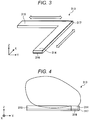
- FIG. 3 is a diagram showing an example of a direction of a current flowing through the first antenna element 314 and the second antenna element 315.
- FIG. 4 is a front view for showing an example of a reading area formed by the antenna 31.
- FIG. 5 is a left side view showing an example of a reading area formed by the antenna 31.
- the first antenna element 314 has a rectangular shape extending in the X direction.
- the second antenna element 315 has a rectangular shape extending in the Y direction.
- the first antenna element 314 and the second antenna element 315 form a conjugate angle at the ends of the antenna elements. More specifically, the first antenna element 314 and the second antenna element 315 are disposed so that the angle formed by the first and second antenna elements is a substantially right angle.
- the bottom surface of the antenna element 313 is covered with a bottom surface conductor portion 316.
- a part of the side surface of the antenna element 313 is covered with a side surface conductor portion 317. More specifically, among the common angles formed by the first antenna element 314 and the second antenna element 315, the side surface on the major angle side (i.e., side of the antenna element 313 where the angle formed by the first antenna element 314 and the second antenna element 315 is greater than 180 degrees) is covered with the side surface conductor portion 317.
- the bottom surface conductor portion 316 and the side surface conductor portion 317 are formed of a conductor such as a metal.
- a high-frequency signal current flows through the first antenna element 314 in the X direction, that is, in the longitudinal direction of the first antenna element 314. Therefore, the first antenna element 314 radiates a linearly polarized wave in a direction orthogonal to the direction in which the high-frequency signal current flows, that is, in the Y direction.
- a high-frequency signal current flows through the second antenna element 315 in the Y direction, that is, in the longitudinal direction of the second antenna element 315. Therefore, the second antenna element 315 radiates a linearly polarized wave in a direction orthogonal to the direction in which the high-frequency signal current flows, that is, in the Y direction. That is, the first antenna element 314 and the second antenna element 315 radiate radio waves with a phase difference of 90 degrees.
- the bottom surface of the antenna element 313 is covered with the bottom surface conductor portion 316, and the side surface on the major angle side is covered with the side surface conductor portion 317.
- the bottom surface conductor portion 316 and the side surface conductor portion 317 reflect radio waves radiated from the antenna element 313 so that radiation of radio waves in the direction of the bottom surface side and the direction of the major angle side is reduced and radio waves are strengthened in the upward and inferior side direction.
- the first antenna element 314 radiates radio waves in the upward and inferior angle side direction to form a reading area of the wireless tag 42.
- the second antenna element 315 radiates radio waves in the upward and inferior angle side direction to form a reading area of the wireless tag 42. That is, the antenna element 313 may form a reading area in an area where the wireless tag 42 is supposed to be held.
- the wireless tag 42 may not communicate.
- the first antenna element 314 and the second antenna element 315 radiate linearly polarized waves so that the waves are substantially orthogonal to each other. Therefore, the first antenna element 314 and the second antenna element 315 may improve the communication accuracy.
- the code symbol reading apparatus 20 is disposed in the hollow portion 312. That is, the code symbol reading apparatus 20 is disposed inside the vertex formed by the first antenna element 314 and the second antenna element 315. Then, the code symbol reading apparatus 20 radiates the laser light for reading the code symbol 41 toward the front surface, the left side surface, or the like in FIG. 2 .
- the antenna element 313 forms a reading area in the areas shown in FIGS. 4 and 5 . Therefore, since the reading area of the code symbol reading apparatus 20 and the reading area of the wireless tag reading apparatus 30 are overlapped, both the apparatuses may execute reading processing by holding the article 4 once.
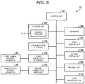
- FIG. 6 is a block diagram showing an example of a hardware configuration of the POS terminal 10.
- the POS terminal 10 includes a control unit 101, a storage unit 102, a communication interface 103, a first connection interface 104, a second connection interface 105, a keyboard 106, a first display unit 107, a second display unit 108, a printing unit 109, and a card reader/writer 110.
- the control unit 101 is a computer that controls the overall operation of the POS terminal 10 and performs various functions of the POS terminal 10.
- the control unit 101 includes a central processing unit (CPU), a read only memory (ROM), and a random access memory (RAM).
- the CPU comprehensively controls the operation of the POS terminal 10.
- the ROM is a storage medium that stores various programs and data.
- the RAM is a storage medium that temporarily stores various programs and various data. Then, the CPU executes a program stored in the ROM or the storage unit 102 or the like with the RAM as a work area.
- the storage unit 102 is a storage device such as a hard disk drive (HDD) or a solid state drive (SSD) .
- the storage unit 102 stores a control program 111.
- the control program 111 is a program for causing the operating system or the functions of the POS terminal 10 to be executed.
- the control program 111 includes a program for exercising the characteristic functions according to the present embodiment.
- the communication interface 103 is an interface for communicating with various apparatus connected to the network.
- the first connection interface 104 is an interface for communicating with the code symbol reading apparatus 20.
- the second connection interface 105 is an interface for communicating with the wireless tag reading apparatus 30.
- the keyboard 106 includes various keys for operating the POS terminal 10.
- the first display unit 107 is a liquid crystal display device or the like having a touch panel stacked on a display surface. For example, the first display unit 107 displays various screens to a clerk of the store.
- the second display unit 108 is a liquid crystal display apparatus or the like in which a touch panel is stacked on the display surface. For example, the second display unit 108 displays various screens for customers.
- the printing unit 109 is a printer that prints a receipt or the like showing transaction details, point status, and the like on paper.
- the card reader/writer 110 is an apparatus that reads and writes information stored in a storage medium such as a magnetic material attached to a card.
- FIG. 7 is a block diagram showing an example of a hardware configuration of the code symbol reading apparatus 20.
- the code symbol reading apparatus 20 includes a control unit 201, a connection interface 202, and a scanner 203.
- the control unit 201 is a computer that controls the overall operation of the code symbol reading apparatus 20 and performs various functions of the code symbol reading apparatus 20.
- the control unit 201 includes a CPU, a ROM, and a RAM.
- the CPU comprehensively controls the operation of the code symbol reading apparatus 20.
- the ROM is a storage medium that stores various programs and data.
- the RAM is a storage medium that temporarily stores various programs and various data. Then, the CPU executes a program stored in a storage medium such as a ROM with the RAM as a work area.
- connection interface 202 is an interface for communicating with the POS terminal 10.
- the scanner 203 radiates light and receives the reflected light. As a result, the scanner 203 reads the code symbol 41 or the like.
- FIG. 8 is a block diagram showing an example of a hardware configuration of the wireless tag reading apparatus 30.
- the wireless tag reading apparatus 30 includes a control circuit 301, a connection interface 302, a transmission circuit 303, a reception circuit 304, and an antenna 31. Further, the antenna 31 includes a first antenna element 314, a second antenna element 315, and a branching circuit 319.
- the control circuit 301 is a computer that controls the overall operation of the wireless tag reading apparatus 30 and performs various functions of the wireless tag reading apparatus 30.
- the control circuit 301 includes a CPU, a ROM, and a RAM.
- the CPU comprehensively controls the operation of the wireless tag reading apparatus 30.
- the ROM is a storage medium that stores various programs and data.
- the RAM is a storage medium that temporarily stores various programs and various data. Then, the CPU executes a program stored in a storage medium such as a ROM with the RAM as a work area.
- connection interface 302 is an interface for communicating with the POS terminal 10.
- the transmission circuit 303 includes an encoding circuit, a modulation circuit, a filter circuit, and an amplifier circuit.
- the transmission circuit 303 converts the digital signals output from the control circuit by these circuits into high-frequency analog signals. Then, the transmission circuit 303 outputs a high-frequency analog signal.
- the reception circuit 304 includes a demodulation circuit, a filter circuit, and a decoding circuit.
- the reception circuit 304 converts high-frequency analog signals output from the first antenna element 314 or the second antenna element 315 by these circuits into digital signals. Then, the reception circuit 304 outputs digital signals.
- the branching circuit 319 is an electronic circuit that outputs a high-frequency analog signal in each direction branched into two directions, that is, the first antenna element 314 and the second antenna element 315. More specifically, the branching circuit 319 outputs the high-frequency analog signal input from the transmission circuit 303 to the first antenna element 314 and the second antenna element 315. In addition, the branching circuit 319 outputs the high-frequency analog signal input from the first antenna element 314 and the second antenna element 315 to the reception circuit 304.
- FIG. 9 is a block diagram showing an example of a hardware configuration of the wireless tag 42.
- the wireless tag 42 includes an antenna 421, a transmission/reception circuit 422, and a storage unit 423.
- the antenna 421 transmits and receives radio waves and the like.
- the transmission/reception circuit 422 generates electric power by electromagnetic induction or the like by using radio waves received by the antenna 421. Then, the transmission/reception circuit 422 executes reading processing and writing processing by using the generated power.
- the transmission/reception circuit 422 causes the information of the storage unit 423 to be transmitted to the antenna 421.
- the transmission/reception circuit 422 writes the information included in the received radio wave into the storage unit 423.
- the storage unit 423 is a nonvolatile rewritable storage medium that may store information even when power is not supplied.
- the storage unit 423 stores, for example, an identification code identifying the wireless tag 42.
- the storage unit 423 may store any information instead of or in addition to the identification code.
- FIG. 10 is a block diagram showing an example of the functional configuration of each apparatus of the reading system 1.
- the control unit 101 of the POS terminal 10 loads the control program 111 stored in the storage unit 102 onto the RAM and operates according to the control program 111 to generate respective functional units shown in FIG. 10 on the RAM.
- the control unit 101 of the POS terminal 10 includes a connection control unit 1001, a commodity registration unit 1002, a checkout processing unit 1003, a reading management unit 1004, and an output control unit 1005 as functional units.
- connection control unit 1001 controls the first connection interface 104 to execute communication with the code symbol reading apparatus 20.
- connection control unit 1001 controls the second connection interface 105 to execute communication with the wireless tag reading apparatus 30.
- the commodity registration unit 1002 controls sales registration of commodities to be sold. When a commodity code identifying a commodity is input, the commodity registration unit 1002 registers the commodity specified by the commodity code.
- the checkout processing unit 1003 controls the checkout processing of the commodities registered by the commodity registration unit 1002. For example, the checkout processing unit 1003 calculates the total price of commodities registered by the commodity registration unit 1002. In addition, the checkout processing unit 1003 calculates the change by subtracting the total price from the amount received from a customer.
- the reading management unit 1004 controls reading processing by the code symbol reading apparatus 20 and the wireless tag reading apparatus 30. For example, when receiving an operation or the like to start the reading processing, the reading management unit 1004 causes the connection control unit 1001 to transmit a read start request for requesting the start of reading processing.
- the reading management unit 1004 may cause the reading apparatus of both the code symbol reading apparatus 20 and the wireless tag reading apparatus 30 to transmit read start requests at once or may cause the both the reading apparatuses to transmit a read start request separately.
- the reading management unit 1004 causes the connection control unit 1001 to transmit a read end request for requesting the end of the reading processing, for example, in the case of reading an operation of ending the reading processing or a reading result of the reading processing.
- the reading management unit 1004 specifies the article 4 held over by using the reading result received by the connection control unit 1001. For example, the reading management unit 1004 specifies the article 4 held from the information included in the reading result of either one of the reading result of the code symbol reading apparatus 20 and the reading result of the wireless tag reading apparatus 30. In addition, the reading management unit 1004 may specify the article 4 held over on the condition that the same information is included in both the reading result of the code symbol reading apparatus 20 and the reading result of the wireless tag reading apparatus 30.
- the reading management unit 1004 may specify that the article 4 is held over the composite result of the reading result of the code symbol reading apparatus 20 and the reading result of the wireless tag reading apparatus 30.
- the time limit may be specified by the reading result of the code symbol reading apparatus 20 and the type of the coupon may be specified by the reading result of the wireless tag reading apparatus 30.
- the output control unit 1005 outputs the reading result.
- the output control unit 1005 controls the first display unit 107 and the second display unit 108 to display and output the reading result.
- the output control unit 1005 controls the printing unit 109 to print out the reading result.
- the control unit 201 of the code symbol reading apparatus 20 loads the program stored in the ROM onto the RAM and operates according to the program to generate the respective functional units shown in FIG. 10 on the RAM.
- the control unit 201 of the code symbol reading apparatus 20 includes a connection control unit 2001 and a reading control unit 2002 as functional units.
- connection control unit 2001 controls the connection interface 202 to execute communication with the POS terminal 10.
- the reading control unit 2002 controls the scanner 203 to execute reading processing. For example, the reading control unit 2002 starts reading processing when the connection control unit 2001 receives a read start request. When reading the code symbol 41, the reading control unit 2002 causes the connection control unit 2001 to transmit the reading result including the information included in the read code symbol 41. When the connection control unit 2001 receives the read end request, the reading control unit 2002 ends the reading processing.
- the control circuit 301 of the wireless tag reading apparatus 30 loads the program stored in the ROM onto the RAM and operates according to the program to generate the respective functional units shown in FIG. 10 on the RAM.
- the control circuit 301 of the wireless tag reading apparatus 30 includes a connection control unit 3001 and a reading control unit 3002 as functional units.
- connection control unit 3001 controls the connection interface 302 to execute communication with the POS terminal 10.
- the reading control unit 3002 controls the transmission circuit 303, the reception circuit 304, and the antenna 31 to execute reading processing. For example, the reading control unit 3002 starts reading processing when the connection control unit 3001 receives a read start request.
- the reading control unit 3002 causes the connection control unit 3001 to transmit the reading result including the read information when the reading processing is ended.
- the connection control unit 3001 receives the read end request, the reading control unit 3002 ends the reading processing.
- the antenna element 313 extends in two directions and includes the first antenna element 314 and the second antenna element 315. That is, the antenna element 313 is not disposed in the vicinity where the operator holding the wireless tag 42 holds the wireless tag 42. Further, the bottom surface of the antenna element 313 is covered with the bottom surface conductor portion 316 formed of a conductor. In addition, a part of the side surface of the antenna element 313 is covered with the side surface conductor portion 317. Therefore, the antenna 31 forms a read area having high radio field intensity above the inner sides of the first antenna element 314 and the second antenna element 315. Therefore, the antenna 31 of the wireless tag reading apparatus 30 according to the present embodiment may reduce deterioration of the radiation characteristics of radio waves.
- the second reading apparatus is not limited to the code symbol reading apparatus 20, but may be another reading apparatus.
- the second reading apparatus may be a reading apparatus that reads the wireless tag 42 corresponding to a frequency band different from that of the wireless tag reading apparatus 30 as the first reading apparatus.
- the first antenna element 314 and the second antenna element 315 form a single structure of the antenna element 313.
- the first antenna element 314 and the second antenna element 315 may be separate antenna elements.
- the programs to be executed by each device of the above embodiment or modification examples are assumed to be provided by being incorporated in advance in a storage medium (ROM or storage unit) included in each device, but are not limited thereto.
- the programs may be configured to be recorded and provided in a computer-readable recording medium such as a CD-ROM, a flexible disk (FD), a CD-R, a digital versatile disk (DVD) or the like in a file in an installable format or an executable format.
- the storage medium is not limited to a medium independent of a computer or an embedded system, but includes a storage medium in which a program transmitted by a LAN, the Internet, or the like is downloaded and stored or temporarily stored.
- programs to be executed by each device of the above embodiment or modification examples may be stored on a computer connected to a network such as the Internet and configured to be provided by being downloaded via the network, and configured to be provided or distributed via the network as the Internet.
Landscapes
- Engineering & Computer Science (AREA)
- Physics & Mathematics (AREA)
- Toxicology (AREA)
- Health & Medical Sciences (AREA)
- Computer Vision & Pattern Recognition (AREA)
- Artificial Intelligence (AREA)
- General Physics & Mathematics (AREA)
- Theoretical Computer Science (AREA)
- Electromagnetism (AREA)
- General Health & Medical Sciences (AREA)
- Computer Networks & Wireless Communication (AREA)
- Computer Security & Cryptography (AREA)
- Cash Registers Or Receiving Machines (AREA)
- Variable-Direction Aerials And Aerial Arrays (AREA)
Abstract

Description
- This application is based upon and claims the benefit of priority from Japanese Patent Application No.
2018-022792, filed in February 13, 2018 - Embodiments described herein relate generally to an antenna device and a reading system.
- In the related art, there is known a wireless tag reading apparatus that reads and writes information from and into a wireless tag, such as a radio frequency identification (RFID) tag, an electronic tag, and a transponder.
- For example, the wireless tag is embedded in a portable article, such as a card and a smartphone. When such an article is held over an antenna of the reading apparatus, a connection is established and information is exchanged therebetween.
- However, since a human hand is a dielectric, when the hand is brought close to the antenna, the radiation of the radio waves from the reader is hindered, which results in failure of connection. Thus, a technique of reducing such deterioration is desired.
- One of the objects of the present invention is to improve prior art techniques and overcome at least some of the prior art problems as for instance above illustrated.
- According to a first aspect of the invention, it is provided an antenna device of a reading apparatus configured to read a wireless tag, the device comprising: a housing; an antenna element bent and extending in first and second directions within the housing; a first conductor that covers a bottom surface of the antenna element; and a second conductor that covers one or more of side surfaces of the antenna element on a major angle side thereof.
- Optionally, in the device according to the first aspect of the invention, the antenna element is bent at a right angle and the major angle is 270 degrees.
- Optionally, the device according to the first aspect of the invention further comprises a branching circuit, wherein the antenna element comprises first and second portions extending in the first and second directions, respectively, and the branching circuit is configured to output an analog signal to each of the first and second portions.
- Optionally, in the device according to the first aspect of the invention, the branching circuit outputs the signal in response to a signal transmitted from a transmitter of the reading apparatus.
- Optionally, in the device according to the first aspect of the invention, the branching circuit outputs a signal to a receiver of the reading apparatus when a signal from the wireless tag is received by the antenna element.
- Optionally, in the device according to the first aspect of the invention, the housing has a rectangular shape, and the first and second directions are parallel to two adjacent side surfaces of the housing.
- Optionally, in the device according to the first aspect of the invention, the antenna element is a substrate antenna formed on a substrate within the housing.
- Optionally, in the device according to the first aspect of the invention, the the housing has an opening partially surrounded by the antenna element.
- Optionally, in the device according to the first aspect of the invention, the opening has a rectangular shape.
- Optionally, in the device according to the first aspect of the invention, the wireless tag is an RFID tag.
- According to a second aspect of the invention, it is provided a reading system comprising a first reading apparatus configured to read a symbol code by using a laser beam; and a second reading apparatus configured to read a wireless tag and comprising: a housing, an antenna element bent and extending in first and second directions within the housing, a first conductor that covers a bottom surface of the antenna element, and a second conductor that covers one or more of side surfaces of the antenna element on a major angle side thereof.
- Optionally, in the system according to the second aspect of the invention, the housing of the second reading apparatus has an opening, and the first reading apparatus is located in the opening.
- Optionally, in the system according to the second aspect of the invention, the symbol code and the wireless tag are printed and attached to an article sold in a grocery store.
- Optionally, in the system according to the second aspect of the invention, the antenna element is bent at a right angle and the major angle is 270 degrees.
- Optionally, in the system according to the second aspect of the invention, the second reading apparatus comprises a branching circuit, the antenna elements comprise first and second portions extending in the first and second directions, and the branching circuit is configured to output an analog signal to each of the first and second portions.
- Optionally, in the system according to the second aspect of the invention, the second reading apparatus comprises a transmitter, and the branching circuit outputs the signal in response to a signal transmitted from the transmitter.
- Optionally, in the system according to the second aspect of the invention, the second reading apparatus comprises a receiver, and the branching circuit outputs a signal to the receiver when a signal from the wireless tag is received by the antenna element.
- Optionally, in the system according to the second aspect of the invention, the housing has a rectangular shape, and the first and second directions are parallel to two adjacent side surfaces of the housing.
- Optionally, in the system according to the second aspect of the invention, the antenna element is a substrate antenna formed on a substrate within the housing.
- Optionally, in the system according to the second aspect of the invention, the housing has an opening partially surrounded by the antenna element.
- Optionally, in the system according to the second aspect of the invention the opening has a rectangular shape.
-
-
FIG. 1 is a diagram showing a reading system according to an embodiment. -
FIG. 2 is a perspective view of an antenna. -
FIG. 3 is a diagram showing an example of a direction of a current flowing through a first antenna element and a second antenna element. -
FIG. 4 is a front view showing an example of a reading area formed by the antenna. -
FIG. 5 is a left side view showing an example of a reading area formed by the antenna. -
FIG. 6 is a block diagram showing an example of a hardware configuration of a POS terminal. -
FIG. 7 is a block diagram showing an example of a hardware configuration of a code symbol reading apparatus. -
FIG. 8 is a block diagram showing an example of a hardware configuration of a wireless tag reading apparatus. -
FIG. 9 is a block diagram showing an example of a hardware configuration of a wireless tag. -
FIG. 10 is a block diagram showing an example of a functional configuration of each apparatus included in the reading system. - One or more embodiments provide an antenna device and a reading system capable of reducing deterioration of radiation characteristics of radio waves.
- According to one embodiment, there is provided an antenna device of a reading apparatus configured to read a wireless tag. The antenna device includes a housing, an antenna element bent and extending in first and second directions within the housing, a first conductor that covers a bottom surface of the antenna element, and a second conductor that covers one or more of side surfaces of the antenna element on a major angle side thereof..
- Embodiments of an antenna device and a reading system will be described in detail below with reference to the accompanying drawings. The embodiments to be described below are directed to the antenna device and the reading system but are not limited to the described configuration, specifications, and the like thereof. The antenna and the reading system of one of the embodiments are applied to a point of sales (POS) terminal connected to an antenna that transmits and receives radio waves to and from a wireless tag at a store such as a supermarket and the like.
-
FIG. 1 is a diagram showing a reading system 1 according to the present embodiment. The reading system 1 includes aPOS terminal 10, a codesymbol reading apparatus 20, and a wirelesstag reading apparatus 30. ThePOS terminal 10 is communicably connected to the codesymbol reading apparatus 20 and the wirelesstag reading apparatus 30. The reading system 1 reads acode symbol 41 included in anarticle 4 or awireless tag 42 included in anarticle 4 by each apparatus. - The
POS terminal 10 is an information processing apparatus that executes sales registration for registering commodities to be sold and checkout processing of commodities registered through sales registration. In addition, thePOS terminal 10 requests the codesymbol reading apparatus 20 and the wirelesstag reading apparatus 30 to execute reading processing of a reading target. Then, thePOS terminal 10 receives the execution result of the reading processing from the codesymbol reading apparatus 20 and the wirelesstag reading apparatus 30. - The code
symbol reading apparatus 20 is a reading apparatus that reads thecode symbol 41 such as a bar code, a two-dimensional code, and the like. The codesymbol reading apparatus 20 reads thecode symbol 41 with reflected light by, for example, radiating a laser beam. The codesymbol reading apparatus 20 executes reading processing when receiving a request to execute reading processing from thePOS terminal 10. Then, the codesymbol reading apparatus 20 transmits the reading result by the reading processing to thePOS terminal 10. - The wireless
tag reading apparatus 30 is a reading apparatus that executes reading and writing of various kinds of information to and from thewireless tag 42 by executing wireless communication with thewireless tag 42 called a radio frequency identification (RFID) tag, an electronic tag, or a responder. When the wirelesstag reading apparatus 30 receives a request to execute the reading processing from thePOS terminal 10, the wirelesstag reading apparatus 30 transmits a radio wave for reading thewireless tag 42. In addition, the wirelesstag reading apparatus 30 receives various kinds of information stored in thewireless tag 42 from thewireless tag 42. In this manner, the wirelesstag reading apparatus 30 executes the reading processing. Then, the wirelesstag reading apparatus 30 transmits the reading result by the reading processing to thePOS terminal 10. - Next, an
antenna 31 of the wirelesstag reading apparatus 30 will be described. Here,FIG. 2 is a perspective view showing an example of theantenna 31. - The
antenna 31 includes arectangular housing 311 having ahollow portion 312. In thehollow portion 312, the codesymbol reading apparatus 20 is disposed. The codesymbol reading apparatus 20 radiates a laser beam for reading thecode symbol 41, for example, toward the front surface or the left side surface inFIG. 2 . In addition, thehollow portion 312 shown inFIG. 2 has a rectangular shape, but may have a circular shape or may have a shape conformed to the shape of the codesymbol reading apparatus 20. - The
antenna 31 includes anantenna element 313 branching into two directions inside thehousing 311. Theantenna element 313 is, for example, a substrate antenna formed on a substrate. Hereinafter, theantenna element 313 extending in an X direction shown inFIG. 2 will be referred to as afirst antenna element 314. In addition, theantenna element 313 extending in a Y direction shown inFIG. 2 is referred to as asecond antenna element 315. - In the present embodiment, the wireless
tag reading apparatus 30 is disposed on the right front side of an operator as seen from the operator holding thewireless tag 42. Then, the operator holds thewireless tag 42 in his or her right hand and holds thewireless tag 42 over theantenna 31 from above. In this case, the operator holds thewireless tag 42 from the direction of the front side or the left side of thehousing 311. Therefore, the wirelesstag reading apparatus 30 reads thewireless tag 42 possessed by the hand entering from the direction of the front side or the left side of thehousing 311. - Next, the
antenna element 313 will be described in detail. -
FIG. 3 is a diagram showing an example of a direction of a current flowing through thefirst antenna element 314 and thesecond antenna element 315.FIG. 4 is a front view for showing an example of a reading area formed by theantenna 31.FIG. 5 is a left side view showing an example of a reading area formed by theantenna 31. - The
first antenna element 314 has a rectangular shape extending in the X direction. Thesecond antenna element 315 has a rectangular shape extending in the Y direction. Thefirst antenna element 314 and thesecond antenna element 315 form a conjugate angle at the ends of the antenna elements. More specifically, thefirst antenna element 314 and thesecond antenna element 315 are disposed so that the angle formed by the first and second antenna elements is a substantially right angle. - The bottom surface of the
antenna element 313 is covered with a bottomsurface conductor portion 316. In addition, in theantenna element 313, a part of the side surface of theantenna element 313 is covered with a sidesurface conductor portion 317. More specifically, among the common angles formed by thefirst antenna element 314 and thesecond antenna element 315, the side surface on the major angle side (i.e., side of theantenna element 313 where the angle formed by thefirst antenna element 314 and thesecond antenna element 315 is greater than 180 degrees) is covered with the sidesurface conductor portion 317. The bottomsurface conductor portion 316 and the sidesurface conductor portion 317 are formed of a conductor such as a metal. - A high-frequency signal current flows through the
first antenna element 314 in the X direction, that is, in the longitudinal direction of thefirst antenna element 314. Therefore, thefirst antenna element 314 radiates a linearly polarized wave in a direction orthogonal to the direction in which the high-frequency signal current flows, that is, in the Y direction. In addition, a high-frequency signal current flows through thesecond antenna element 315 in the Y direction, that is, in the longitudinal direction of thesecond antenna element 315. Therefore, thesecond antenna element 315 radiates a linearly polarized wave in a direction orthogonal to the direction in which the high-frequency signal current flows, that is, in the Y direction. That is, thefirst antenna element 314 and thesecond antenna element 315 radiate radio waves with a phase difference of 90 degrees. - In addition, the bottom surface of the
antenna element 313 is covered with the bottomsurface conductor portion 316, and the side surface on the major angle side is covered with the sidesurface conductor portion 317. The bottomsurface conductor portion 316 and the sidesurface conductor portion 317 reflect radio waves radiated from theantenna element 313 so that radiation of radio waves in the direction of the bottom surface side and the direction of the major angle side is reduced and radio waves are strengthened in the upward and inferior side direction. As a result, as shown inFIG. 4 , thefirst antenna element 314 radiates radio waves in the upward and inferior angle side direction to form a reading area of thewireless tag 42. Similarly, as shown inFIG. 5 , thesecond antenna element 315 radiates radio waves in the upward and inferior angle side direction to form a reading area of thewireless tag 42. That is, theantenna element 313 may form a reading area in an area where thewireless tag 42 is supposed to be held. - Here, when linearly polarized waves are radiated from one direction, depending on the orientation of the antenna 421 (see
FIG. 9 ) of thewireless tag 42, thewireless tag 42 may not communicate. However, thefirst antenna element 314 and thesecond antenna element 315 radiate linearly polarized waves so that the waves are substantially orthogonal to each other. Therefore, thefirst antenna element 314 and thesecond antenna element 315 may improve the communication accuracy. - In addition, the code
symbol reading apparatus 20 is disposed in thehollow portion 312. That is, the codesymbol reading apparatus 20 is disposed inside the vertex formed by thefirst antenna element 314 and thesecond antenna element 315. Then, the codesymbol reading apparatus 20 radiates the laser light for reading thecode symbol 41 toward the front surface, the left side surface, or the like inFIG. 2 . In addition, theantenna element 313 forms a reading area in the areas shown inFIGS. 4 and5 . Therefore, since the reading area of the codesymbol reading apparatus 20 and the reading area of the wirelesstag reading apparatus 30 are overlapped, both the apparatuses may execute reading processing by holding thearticle 4 once. - Next, the hardware configuration of each apparatus included in the reading system 1 will be described.
-
FIG. 6 is a block diagram showing an example of a hardware configuration of thePOS terminal 10. ThePOS terminal 10 includes a control unit 101, astorage unit 102, acommunication interface 103, afirst connection interface 104, asecond connection interface 105, akeyboard 106, a first display unit 107, asecond display unit 108, aprinting unit 109, and a card reader/writer 110. - The control unit 101 is a computer that controls the overall operation of the
POS terminal 10 and performs various functions of thePOS terminal 10. The control unit 101 includes a central processing unit (CPU), a read only memory (ROM), and a random access memory (RAM). The CPU comprehensively controls the operation of thePOS terminal 10. The ROM is a storage medium that stores various programs and data. The RAM is a storage medium that temporarily stores various programs and various data. Then, the CPU executes a program stored in the ROM or thestorage unit 102 or the like with the RAM as a work area. - The
storage unit 102 is a storage device such as a hard disk drive (HDD) or a solid state drive (SSD) . Thestorage unit 102 stores acontrol program 111. Thecontrol program 111 is a program for causing the operating system or the functions of thePOS terminal 10 to be executed. Thecontrol program 111 includes a program for exercising the characteristic functions according to the present embodiment. - The
communication interface 103 is an interface for communicating with various apparatus connected to the network. - The
first connection interface 104 is an interface for communicating with the codesymbol reading apparatus 20. Thesecond connection interface 105 is an interface for communicating with the wirelesstag reading apparatus 30. - The
keyboard 106 includes various keys for operating thePOS terminal 10. - The first display unit 107 is a liquid crystal display device or the like having a touch panel stacked on a display surface. For example, the first display unit 107 displays various screens to a clerk of the store. The
second display unit 108 is a liquid crystal display apparatus or the like in which a touch panel is stacked on the display surface. For example, thesecond display unit 108 displays various screens for customers. - The
printing unit 109 is a printer that prints a receipt or the like showing transaction details, point status, and the like on paper. The card reader/writer 110 is an apparatus that reads and writes information stored in a storage medium such as a magnetic material attached to a card. -
FIG. 7 is a block diagram showing an example of a hardware configuration of the codesymbol reading apparatus 20. The codesymbol reading apparatus 20 includes acontrol unit 201, aconnection interface 202, and ascanner 203. - The
control unit 201 is a computer that controls the overall operation of the codesymbol reading apparatus 20 and performs various functions of the codesymbol reading apparatus 20. Thecontrol unit 201 includes a CPU, a ROM, and a RAM. The CPU comprehensively controls the operation of the codesymbol reading apparatus 20. The ROM is a storage medium that stores various programs and data. The RAM is a storage medium that temporarily stores various programs and various data. Then, the CPU executes a program stored in a storage medium such as a ROM with the RAM as a work area. - The
connection interface 202 is an interface for communicating with thePOS terminal 10. - The
scanner 203 radiates light and receives the reflected light. As a result, thescanner 203 reads thecode symbol 41 or the like. -
FIG. 8 is a block diagram showing an example of a hardware configuration of the wirelesstag reading apparatus 30. The wirelesstag reading apparatus 30 includes acontrol circuit 301, aconnection interface 302, a transmission circuit 303, areception circuit 304, and anantenna 31. Further, theantenna 31 includes afirst antenna element 314, asecond antenna element 315, and a branching circuit 319. - The
control circuit 301 is a computer that controls the overall operation of the wirelesstag reading apparatus 30 and performs various functions of the wirelesstag reading apparatus 30. Thecontrol circuit 301 includes a CPU, a ROM, and a RAM. The CPU comprehensively controls the operation of the wirelesstag reading apparatus 30. The ROM is a storage medium that stores various programs and data. The RAM is a storage medium that temporarily stores various programs and various data. Then, the CPU executes a program stored in a storage medium such as a ROM with the RAM as a work area. - The
connection interface 302 is an interface for communicating with thePOS terminal 10. - The transmission circuit 303 includes an encoding circuit, a modulation circuit, a filter circuit, and an amplifier circuit. The transmission circuit 303 converts the digital signals output from the control circuit by these circuits into high-frequency analog signals. Then, the transmission circuit 303 outputs a high-frequency analog signal.
- The
reception circuit 304 includes a demodulation circuit, a filter circuit, and a decoding circuit. Thereception circuit 304 converts high-frequency analog signals output from thefirst antenna element 314 or thesecond antenna element 315 by these circuits into digital signals. Then, thereception circuit 304 outputs digital signals. - The branching circuit 319 is an electronic circuit that outputs a high-frequency analog signal in each direction branched into two directions, that is, the
first antenna element 314 and thesecond antenna element 315. More specifically, the branching circuit 319 outputs the high-frequency analog signal input from the transmission circuit 303 to thefirst antenna element 314 and thesecond antenna element 315. In addition, the branching circuit 319 outputs the high-frequency analog signal input from thefirst antenna element 314 and thesecond antenna element 315 to thereception circuit 304. -
FIG. 9 is a block diagram showing an example of a hardware configuration of thewireless tag 42. Thewireless tag 42 includes an antenna 421, a transmission/reception circuit 422, and astorage unit 423. - The antenna 421 transmits and receives radio waves and the like.
- The transmission/
reception circuit 422 generates electric power by electromagnetic induction or the like by using radio waves received by the antenna 421. Then, the transmission/reception circuit 422 executes reading processing and writing processing by using the generated power. - In addition, when the antenna 421 receives a radio wave for reading the information stored in the
wireless tag 42, the transmission/reception circuit 422 causes the information of thestorage unit 423 to be transmitted to the antenna 421. When the antenna 421 receives a radio wave for writing information to thewireless tag 42, the transmission/reception circuit 422 writes the information included in the received radio wave into thestorage unit 423. - The
storage unit 423 is a nonvolatile rewritable storage medium that may store information even when power is not supplied. Thestorage unit 423 stores, for example, an identification code identifying thewireless tag 42. Thestorage unit 423 may store any information instead of or in addition to the identification code. - Next, the functions of the respective apparatuses included in the reading system 1 will be described. Here,
FIG. 10 is a block diagram showing an example of the functional configuration of each apparatus of the reading system 1. - The control unit 101 of the
POS terminal 10 loads thecontrol program 111 stored in thestorage unit 102 onto the RAM and operates according to thecontrol program 111 to generate respective functional units shown inFIG. 10 on the RAM. Specifically, the control unit 101 of thePOS terminal 10 includes aconnection control unit 1001, a commodity registration unit 1002, a checkout processing unit 1003, areading management unit 1004, and anoutput control unit 1005 as functional units. - The
connection control unit 1001 controls thefirst connection interface 104 to execute communication with the codesymbol reading apparatus 20. In addition, theconnection control unit 1001 controls thesecond connection interface 105 to execute communication with the wirelesstag reading apparatus 30. - The commodity registration unit 1002 controls sales registration of commodities to be sold. When a commodity code identifying a commodity is input, the commodity registration unit 1002 registers the commodity specified by the commodity code.
- The checkout processing unit 1003 controls the checkout processing of the commodities registered by the commodity registration unit 1002. For example, the checkout processing unit 1003 calculates the total price of commodities registered by the commodity registration unit 1002. In addition, the checkout processing unit 1003 calculates the change by subtracting the total price from the amount received from a customer.
- The
reading management unit 1004 controls reading processing by the codesymbol reading apparatus 20 and the wirelesstag reading apparatus 30. For example, when receiving an operation or the like to start the reading processing, thereading management unit 1004 causes theconnection control unit 1001 to transmit a read start request for requesting the start of reading processing. Thereading management unit 1004 may cause the reading apparatus of both the codesymbol reading apparatus 20 and the wirelesstag reading apparatus 30 to transmit read start requests at once or may cause the both the reading apparatuses to transmit a read start request separately. Thereading management unit 1004 causes theconnection control unit 1001 to transmit a read end request for requesting the end of the reading processing, for example, in the case of reading an operation of ending the reading processing or a reading result of the reading processing. - In addition, the
reading management unit 1004 specifies thearticle 4 held over by using the reading result received by theconnection control unit 1001. For example, thereading management unit 1004 specifies thearticle 4 held from the information included in the reading result of either one of the reading result of the codesymbol reading apparatus 20 and the reading result of the wirelesstag reading apparatus 30. In addition, thereading management unit 1004 may specify thearticle 4 held over on the condition that the same information is included in both the reading result of the codesymbol reading apparatus 20 and the reading result of the wirelesstag reading apparatus 30. - In addition, the
reading management unit 1004 may specify that thearticle 4 is held over the composite result of the reading result of the codesymbol reading apparatus 20 and the reading result of the wirelesstag reading apparatus 30. For example, when thearticle 4 to be read is a coupon with time limit, the time limit may be specified by the reading result of the codesymbol reading apparatus 20 and the type of the coupon may be specified by the reading result of the wirelesstag reading apparatus 30. - The
output control unit 1005 outputs the reading result. For example, theoutput control unit 1005 controls the first display unit 107 and thesecond display unit 108 to display and output the reading result. In addition, theoutput control unit 1005 controls theprinting unit 109 to print out the reading result. - The
control unit 201 of the codesymbol reading apparatus 20 loads the program stored in the ROM onto the RAM and operates according to the program to generate the respective functional units shown inFIG. 10 on the RAM. Specifically, thecontrol unit 201 of the codesymbol reading apparatus 20 includes aconnection control unit 2001 and areading control unit 2002 as functional units. - The
connection control unit 2001 controls theconnection interface 202 to execute communication with thePOS terminal 10. - The
reading control unit 2002 controls thescanner 203 to execute reading processing. For example, thereading control unit 2002 starts reading processing when theconnection control unit 2001 receives a read start request. When reading thecode symbol 41, thereading control unit 2002 causes theconnection control unit 2001 to transmit the reading result including the information included in theread code symbol 41. When theconnection control unit 2001 receives the read end request, thereading control unit 2002 ends the reading processing. - The
control circuit 301 of the wirelesstag reading apparatus 30 loads the program stored in the ROM onto the RAM and operates according to the program to generate the respective functional units shown inFIG. 10 on the RAM. Specifically, thecontrol circuit 301 of the wirelesstag reading apparatus 30 includes aconnection control unit 3001 and areading control unit 3002 as functional units. - The
connection control unit 3001 controls theconnection interface 302 to execute communication with thePOS terminal 10. - The
reading control unit 3002 controls the transmission circuit 303, thereception circuit 304, and theantenna 31 to execute reading processing. For example, thereading control unit 3002 starts reading processing when theconnection control unit 3001 receives a read start request. - The
reading control unit 3002 causes theconnection control unit 3001 to transmit the reading result including the read information when the reading processing is ended. When theconnection control unit 3001 receives the read end request, thereading control unit 3002 ends the reading processing. - As described above, according to the
antenna 31 of the wirelesstag reading apparatus 30 according to the present embodiment, theantenna element 313 extends in two directions and includes thefirst antenna element 314 and thesecond antenna element 315. That is, theantenna element 313 is not disposed in the vicinity where the operator holding thewireless tag 42 holds thewireless tag 42. Further, the bottom surface of theantenna element 313 is covered with the bottomsurface conductor portion 316 formed of a conductor. In addition, a part of the side surface of theantenna element 313 is covered with the sidesurface conductor portion 317. Therefore, theantenna 31 forms a read area having high radio field intensity above the inner sides of thefirst antenna element 314 and thesecond antenna element 315. Therefore, theantenna 31 of the wirelesstag reading apparatus 30 according to the present embodiment may reduce deterioration of the radiation characteristics of radio waves. - While certain embodiments have been described, these embodiments have been presented by way of example only, and are not intended to limit the scope of the inventions. Indeed, the novel embodiments described herein may be embodied in a variety of other forms; furthermore, various omissions, substitutions and changes in the form of the embodiments described herein may be made without departing from the scope of the inventions. The accompanying claims and their equivalents are intended to cover such forms or modifications as would fall within the scope of the inventions as defined by the appended claims.
- In addition, in the above embodiment, the case of the code
symbol reading apparatus 20 has been described as an example of the second reading apparatus. However, the second reading apparatus is not limited to the codesymbol reading apparatus 20, but may be another reading apparatus. For example, the second reading apparatus may be a reading apparatus that reads thewireless tag 42 corresponding to a frequency band different from that of the wirelesstag reading apparatus 30 as the first reading apparatus. - In addition, in the above embodiment, the
first antenna element 314 and thesecond antenna element 315 form a single structure of theantenna element 313. However, thefirst antenna element 314 and thesecond antenna element 315 may be separate antenna elements. - The programs to be executed by each device of the above embodiment or modification examples are assumed to be provided by being incorporated in advance in a storage medium (ROM or storage unit) included in each device, but are not limited thereto. For example, the programs may be configured to be recorded and provided in a computer-readable recording medium such as a CD-ROM, a flexible disk (FD), a CD-R, a digital versatile disk (DVD) or the like in a file in an installable format or an executable format. Further, the storage medium is not limited to a medium independent of a computer or an embedded system, but includes a storage medium in which a program transmitted by a LAN, the Internet, or the like is downloaded and stored or temporarily stored.
- In addition, the programs to be executed by each device of the above embodiment or modification examples may be stored on a computer connected to a network such as the Internet and configured to be provided by being downloaded via the network, and configured to be provided or distributed via the network as the Internet.
Claims (15)
- An antenna device of a reading apparatus configured to read a wireless tag, the device comprising:a housing;an antenna element bent and extending in first and second directions within the housing;a first conductor that covers a bottom surface of the antenna element; anda second conductor that covers one or more of side surfaces of the antenna element on a major angle side thereof.
- The device according to claim 1, wherein
the antenna element is bent at a right angle and the major angle is 270 degrees. - The device according to claim 1 or 2, further comprising:a branching circuit, whereinthe antenna element comprises first and second portions extending in the first and second directions, respectively, andthe branching circuit is configured to output an analog signal to each of the first and second portions.
- The device according to claim 3, wherein
the branching circuit outputs the signal in response to a signal transmitted from a transmitter of the reading apparatus. - The device according to claim 5, wherein
the branching circuit outputs a signal to a receiver of the reading apparatus when a signal from the wireless tag is received by the antenna element. - The device according to any of claims 1 to 5, whereinthe housing has a rectangular shape, andthe first and second directions are parallel to two adjacent side surfaces of the housing.
- The device according to any of claims 1 to 6, wherein
the antenna element is a substrate antenna formed on a substrate within the housing. - The device according to any of claims 1 to 7, wherein
the housing has an opening partially surrounded by the antenna element. - The device according to claim 8, wherein
the opening has a rectangular shape. - The device according to any of claims 1 to 9, wherein
the wireless tag is an RFID tag. - A reading system comprising:a first reading apparatus configured to read a symbol code by using a laser beam; anda second reading apparatus configured to read a wireless tag and comprising:a housing,an antenna element bent and extending in first and second directions within the housing,a first conductor that covers a bottom surface of the antenna element, anda second conductor that covers one or more of side surfaces of the antenna element on a major angle side thereof.
- The system according to claim 11, wherein
the housing of the second reading apparatus has an opening, and
the first reading apparatus is located in the opening. - The system according to claim 11 or 12, wherein
the symbol code and the wireless tag are printed and attached to an article sold in a grocery store. - The system according to any of claims 11 to 13, wherein
the antenna element is bent at a right angle and the major angle is 270 degrees. - The system according to any of claims 11 to 14, wherein
the second reading apparatus comprises a branching circuit,
the antenna elements comprise first and second portions extending in the first and second directions, and
the branching circuit is configured to output an analog signal to each of the first and second portions.
Applications Claiming Priority (1)
| Application Number | Priority Date | Filing Date | Title |
|---|---|---|---|
| JP2018022792A JP7010719B2 (en) | 2018-02-13 | 2018-02-13 | Reading system |
Publications (2)
| Publication Number | Publication Date |
|---|---|
| EP3525283A1 true EP3525283A1 (en) | 2019-08-14 |
| EP3525283B1 EP3525283B1 (en) | 2021-10-27 |
Family
ID=65443667
Family Applications (1)
| Application Number | Title | Priority Date | Filing Date |
|---|---|---|---|
| EP19156872.4A Not-in-force EP3525283B1 (en) | 2018-02-13 | 2019-02-13 | Antenna device and reading system |
Country Status (3)
| Country | Link |
|---|---|
| US (2) | US10747969B2 (en) |
| EP (1) | EP3525283B1 (en) |
| JP (1) | JP7010719B2 (en) |
Families Citing this family (2)
| Publication number | Priority date | Publication date | Assignee | Title |
|---|---|---|---|---|
| JP7010719B2 (en) * | 2018-02-13 | 2022-01-26 | 東芝テック株式会社 | Reading system |
| JP7433920B2 (en) * | 2020-01-16 | 2024-02-20 | 東芝テック株式会社 | Wireless tag reader |
Citations (1)
| Publication number | Priority date | Publication date | Assignee | Title |
|---|---|---|---|---|
| US20170373373A1 (en) * | 2016-06-24 | 2017-12-28 | Toshiba Tec Kabushiki Kaisha | Antenna apparatus |
Family Cites Families (18)
| Publication number | Priority date | Publication date | Assignee | Title |
|---|---|---|---|---|
| JPH04134910A (en) * | 1990-09-26 | 1992-05-08 | Shinko Electric Co Ltd | Antenna system |
| US6056199A (en) * | 1995-09-25 | 2000-05-02 | Intermec Ip Corporation | Method and apparatus for storing and reading data |
| US6371375B1 (en) * | 1995-09-25 | 2002-04-16 | Intermec Ip Corp. | Method and apparatus for associating data with a wireless memory device |
| WO2004084344A1 (en) | 2003-03-18 | 2004-09-30 | Sony Ericsson Mobile Communications Ab | Compact diversity antenna |
| JP2005286755A (en) | 2004-03-30 | 2005-10-13 | Matsushita Electric Ind Co Ltd | Chip antenna |
| JP4690758B2 (en) | 2005-03-28 | 2011-06-01 | 東芝テック株式会社 | Desktop wireless tag reading system and wireless tag reading control method |
| US7222785B2 (en) * | 2005-08-16 | 2007-05-29 | Toshiba Tec Kabushiki Kaisha | Commodity information registering apparatus and commodity information registering method |
| JP4845578B2 (en) | 2006-04-19 | 2011-12-28 | 株式会社日本自動車部品総合研究所 | Information terminal equipment |
| JP2009105503A (en) * | 2007-10-19 | 2009-05-14 | Toshiba Corp | Circularly polarized antenna device, semiconductor module, and wireless device |
| JP5227820B2 (en) | 2009-01-26 | 2013-07-03 | 古河電気工業株式会社 | Radar system antenna |
| US20130059553A1 (en) | 2010-05-21 | 2013-03-07 | Nec Corporation | Antenna apparatus, antenna system, and method of adjusting antenna apparatus |
| WO2011145268A1 (en) * | 2010-05-21 | 2011-11-24 | 日本電気株式会社 | Antenna device and adjusting method thereof |
| JP5913773B2 (en) * | 2013-11-21 | 2016-04-27 | レノボ・シンガポール・プライベート・リミテッド | Antennas and portable electronic devices used for near field communication |
| JP2016129320A (en) | 2015-01-09 | 2016-07-14 | 富士通株式会社 | Antenna device |
| SG10201607014SA (en) * | 2016-08-23 | 2018-03-28 | Mastercard Asia Pacific Pte Ltd | Method and system for payment status verification |
| JP2019050521A (en) * | 2017-09-11 | 2019-03-28 | 株式会社東芝 | Antenna apparatus, wireless communication apparatus and signal transmission method |
| JP7010719B2 (en) * | 2018-02-13 | 2022-01-26 | 東芝テック株式会社 | Reading system |
| DE102019103102B4 (en) * | 2019-02-08 | 2021-09-30 | Sick Ag | Antenna for an RFID reader and method for identifying a role |
-
2018
- 2018-02-13 JP JP2018022792A patent/JP7010719B2/en not_active Expired - Fee Related
-
2019
- 2019-02-01 US US16/265,933 patent/US10747969B2/en active Active
- 2019-02-13 EP EP19156872.4A patent/EP3525283B1/en not_active Not-in-force
-
2020
- 2020-07-07 US US16/923,024 patent/US11295097B2/en not_active Expired - Fee Related
Patent Citations (1)
| Publication number | Priority date | Publication date | Assignee | Title |
|---|---|---|---|---|
| US20170373373A1 (en) * | 2016-06-24 | 2017-12-28 | Toshiba Tec Kabushiki Kaisha | Antenna apparatus |
Non-Patent Citations (3)
| Title |
|---|
| AGNEESSENS SAM ET AL: "Compact Half Diamond Dual-Band Textile HMSIW On-Body Antenna", IEEE TRANSACTIONS ON ANTENNAS AND PROPAGATION, IEEE SERVICE CENTER, PISCATAWAY, NJ, US, vol. 62, no. 5, 26 February 2014 (2014-02-26), pages 2374 - 2381, XP011547136, ISSN: 0018-926X, [retrieved on 20140501], DOI: 10.1109/TAP.2014.2308526 * |
| KUMAR KUNDAN ET AL: "Broadband Dual Circularly Polarized Substrate Integrated Waveguide Antenna", IEEE ANTENNAS AND WIRELESS PROPAGATION LETTERS, vol. 16, 26 September 2017 (2017-09-26), pages 2971 - 2974, XP011672853, ISSN: 1536-1225, [retrieved on 20171107], DOI: 10.1109/LAWP.2017.2756093 * |
| SYLVAIN PFLAUM ET AL: "Planar inverted F antenna circularly polarized for RFID applications", ANTENNAS AND PROPAGATION SOCIETY INTERNATIONAL SYMPOSIUM (APSURSI), 2012 IEEE, IEEE, 8 July 2012 (2012-07-08), pages 1 - 2, XP032472362, ISBN: 978-1-4673-0461-0, DOI: 10.1109/APS.2012.6349342 * |
Also Published As
| Publication number | Publication date |
|---|---|
| US20190251305A1 (en) | 2019-08-15 |
| US11295097B2 (en) | 2022-04-05 |
| US20200334427A1 (en) | 2020-10-22 |
| JP2019140549A (en) | 2019-08-22 |
| EP3525283B1 (en) | 2021-10-27 |
| US10747969B2 (en) | 2020-08-18 |
| JP7010719B2 (en) | 2022-01-26 |
Similar Documents
| Publication | Publication Date | Title |
|---|---|---|
| JP7375127B2 (en) | Communication device and communication method | |
| US7902984B2 (en) | Single frequency low power RFID device | |
| US20090289116A1 (en) | Handheld combination bar code and rfid reader with integrated electronics and antenna | |
| EP2595087B1 (en) | Encoded information reading terminal with multi directional antenna | |
| US20100134252A1 (en) | Polarized RFID Antenna with Spatial Diversity | |
| US11295097B2 (en) | Antenna device and reading system | |
| JP5149928B2 (en) | Information processing apparatus, wireless tag reader, and program | |
| US9892297B2 (en) | Arrangement for, and method of, processing products associated with RFID tags and bar code symbols at the same workstation | |
| EP3285201B1 (en) | Reading device and control program for reading device | |
| JP2018028849A (en) | Reading device and program | |
| KR20060038353A (en) | Radiofrequency Identification System with Selectable Backscattering Parameters | |
| US20170330426A1 (en) | Arrangement for, and method of, processing products associated with rfid tags and bar code symbols in the same workstation | |
| CN113892213B (en) | Apparatus, system, and method associated with an RFID tag reader assembly for use in a bar code reader | |
| US20190180062A1 (en) | Wireless tag reading apparatus and wireless tag reading method | |
| JP7206426B2 (en) | Antenna and reading system | |
| JP4887183B2 (en) | Shopping basket and checkout system using this basket | |
| EP3825900B1 (en) | Information processing device, information processing system, and method | |
| JP2006157593A (en) | Rfid communication system and wireless communication device | |
| US20130300538A1 (en) | Rfid tag reader and method for reading an rfid tag | |
| Proffitt II | Experimental investigation to inform optimal configurations for dynamic near-field passive uhf rfid systems | |
| CN118783076A (en) | RFID antennas, RFID tags and RFID systems | |
| JP2022125082A (en) | Cash register system and cash register settlement method | |
| JP2007089005A (en) | Contactless communication system |
Legal Events
| Date | Code | Title | Description |
|---|---|---|---|
| PUAI | Public reference made under article 153(3) epc to a published international application that has entered the european phase |
Free format text: ORIGINAL CODE: 0009012 |
|
| STAA | Information on the status of an ep patent application or granted ep patent |
Free format text: STATUS: THE APPLICATION HAS BEEN PUBLISHED |
|
| STAA | Information on the status of an ep patent application or granted ep patent |
Free format text: STATUS: REQUEST FOR EXAMINATION WAS MADE |
|
| AK | Designated contracting states |
Kind code of ref document: A1 Designated state(s): AL AT BE BG CH CY CZ DE DK EE ES FI FR GB GR HR HU IE IS IT LI LT LU LV MC MK MT NL NO PL PT RO RS SE SI SK SM TR |
|
| AX | Request for extension of the european patent |
Extension state: BA ME |
|
| 17P | Request for examination filed |
Effective date: 20190719 |
|
| RBV | Designated contracting states (corrected) |
Designated state(s): AL AT BE BG CH CY CZ DE DK EE ES FI FR GB GR HR HU IE IS IT LI LT LU LV MC MK MT NL NO PL PT RO RS SE SI SK SM TR |
|
| STAA | Information on the status of an ep patent application or granted ep patent |
Free format text: STATUS: EXAMINATION IS IN PROGRESS |
|
| 17Q | First examination report despatched |
Effective date: 20200529 |
|
| RIC1 | Information provided on ipc code assigned before grant |
Ipc: G06K 7/10 20060101ALI20210422BHEP Ipc: G06K 7/00 20060101ALI20210422BHEP Ipc: H01Q 19/10 20060101ALI20210422BHEP Ipc: H01Q 1/22 20060101AFI20210422BHEP |
|
| GRAP | Despatch of communication of intention to grant a patent |
Free format text: ORIGINAL CODE: EPIDOSNIGR1 |
|
| STAA | Information on the status of an ep patent application or granted ep patent |
Free format text: STATUS: GRANT OF PATENT IS INTENDED |
|
| INTG | Intention to grant announced |
Effective date: 20210608 |
|
| GRAS | Grant fee paid |
Free format text: ORIGINAL CODE: EPIDOSNIGR3 |
|
| GRAA | (expected) grant |
Free format text: ORIGINAL CODE: 0009210 |
|
| STAA | Information on the status of an ep patent application or granted ep patent |
Free format text: STATUS: THE PATENT HAS BEEN GRANTED |
|
| AK | Designated contracting states |
Kind code of ref document: B1 Designated state(s): AL AT BE BG CH CY CZ DE DK EE ES FI FR GB GR HR HU IE IS IT LI LT LU LV MC MK MT NL NO PL PT RO RS SE SI SK SM TR |
|
| REG | Reference to a national code |
Ref country code: GB Ref legal event code: FG4D |
|
| REG | Reference to a national code |
Ref country code: CH Ref legal event code: EP |
|
| REG | Reference to a national code |
Ref country code: AT Ref legal event code: REF Ref document number: 1442665 Country of ref document: AT Kind code of ref document: T Effective date: 20211115 |
|
| REG | Reference to a national code |
Ref country code: DE Ref legal event code: R096 Ref document number: 602019008585 Country of ref document: DE |
|
| REG | Reference to a national code |
Ref country code: IE Ref legal event code: FG4D |
|
| REG | Reference to a national code |
Ref country code: LT Ref legal event code: MG9D |
|
| REG | Reference to a national code |
Ref country code: NL Ref legal event code: MP Effective date: 20211027 |
|
| REG | Reference to a national code |
Ref country code: AT Ref legal event code: MK05 Ref document number: 1442665 Country of ref document: AT Kind code of ref document: T Effective date: 20211027 |
|
| PG25 | Lapsed in a contracting state [announced via postgrant information from national office to epo] |
Ref country code: RS Free format text: LAPSE BECAUSE OF FAILURE TO SUBMIT A TRANSLATION OF THE DESCRIPTION OR TO PAY THE FEE WITHIN THE PRESCRIBED TIME-LIMIT Effective date: 20211027 Ref country code: LT Free format text: LAPSE BECAUSE OF FAILURE TO SUBMIT A TRANSLATION OF THE DESCRIPTION OR TO PAY THE FEE WITHIN THE PRESCRIBED TIME-LIMIT Effective date: 20211027 Ref country code: FI Free format text: LAPSE BECAUSE OF FAILURE TO SUBMIT A TRANSLATION OF THE DESCRIPTION OR TO PAY THE FEE WITHIN THE PRESCRIBED TIME-LIMIT Effective date: 20211027 Ref country code: BG Free format text: LAPSE BECAUSE OF FAILURE TO SUBMIT A TRANSLATION OF THE DESCRIPTION OR TO PAY THE FEE WITHIN THE PRESCRIBED TIME-LIMIT Effective date: 20220127 Ref country code: AT Free format text: LAPSE BECAUSE OF FAILURE TO SUBMIT A TRANSLATION OF THE DESCRIPTION OR TO PAY THE FEE WITHIN THE PRESCRIBED TIME-LIMIT Effective date: 20211027 |
|
| PG25 | Lapsed in a contracting state [announced via postgrant information from national office to epo] |
Ref country code: IS Free format text: LAPSE BECAUSE OF FAILURE TO SUBMIT A TRANSLATION OF THE DESCRIPTION OR TO PAY THE FEE WITHIN THE PRESCRIBED TIME-LIMIT Effective date: 20220227 Ref country code: SE Free format text: LAPSE BECAUSE OF FAILURE TO SUBMIT A TRANSLATION OF THE DESCRIPTION OR TO PAY THE FEE WITHIN THE PRESCRIBED TIME-LIMIT Effective date: 20211027 Ref country code: PT Free format text: LAPSE BECAUSE OF FAILURE TO SUBMIT A TRANSLATION OF THE DESCRIPTION OR TO PAY THE FEE WITHIN THE PRESCRIBED TIME-LIMIT Effective date: 20220228 Ref country code: PL Free format text: LAPSE BECAUSE OF FAILURE TO SUBMIT A TRANSLATION OF THE DESCRIPTION OR TO PAY THE FEE WITHIN THE PRESCRIBED TIME-LIMIT Effective date: 20211027 Ref country code: NO Free format text: LAPSE BECAUSE OF FAILURE TO SUBMIT A TRANSLATION OF THE DESCRIPTION OR TO PAY THE FEE WITHIN THE PRESCRIBED TIME-LIMIT Effective date: 20220127 Ref country code: NL Free format text: LAPSE BECAUSE OF FAILURE TO SUBMIT A TRANSLATION OF THE DESCRIPTION OR TO PAY THE FEE WITHIN THE PRESCRIBED TIME-LIMIT Effective date: 20211027 Ref country code: LV Free format text: LAPSE BECAUSE OF FAILURE TO SUBMIT A TRANSLATION OF THE DESCRIPTION OR TO PAY THE FEE WITHIN THE PRESCRIBED TIME-LIMIT Effective date: 20211027 Ref country code: HR Free format text: LAPSE BECAUSE OF FAILURE TO SUBMIT A TRANSLATION OF THE DESCRIPTION OR TO PAY THE FEE WITHIN THE PRESCRIBED TIME-LIMIT Effective date: 20211027 Ref country code: GR Free format text: LAPSE BECAUSE OF FAILURE TO SUBMIT A TRANSLATION OF THE DESCRIPTION OR TO PAY THE FEE WITHIN THE PRESCRIBED TIME-LIMIT Effective date: 20220128 Ref country code: ES Free format text: LAPSE BECAUSE OF FAILURE TO SUBMIT A TRANSLATION OF THE DESCRIPTION OR TO PAY THE FEE WITHIN THE PRESCRIBED TIME-LIMIT Effective date: 20211027 |
|
| REG | Reference to a national code |
Ref country code: DE Ref legal event code: R097 Ref document number: 602019008585 Country of ref document: DE |
|
| PG25 | Lapsed in a contracting state [announced via postgrant information from national office to epo] |
Ref country code: SM Free format text: LAPSE BECAUSE OF FAILURE TO SUBMIT A TRANSLATION OF THE DESCRIPTION OR TO PAY THE FEE WITHIN THE PRESCRIBED TIME-LIMIT Effective date: 20211027 Ref country code: SK Free format text: LAPSE BECAUSE OF FAILURE TO SUBMIT A TRANSLATION OF THE DESCRIPTION OR TO PAY THE FEE WITHIN THE PRESCRIBED TIME-LIMIT Effective date: 20211027 Ref country code: RO Free format text: LAPSE BECAUSE OF FAILURE TO SUBMIT A TRANSLATION OF THE DESCRIPTION OR TO PAY THE FEE WITHIN THE PRESCRIBED TIME-LIMIT Effective date: 20211027 Ref country code: EE Free format text: LAPSE BECAUSE OF FAILURE TO SUBMIT A TRANSLATION OF THE DESCRIPTION OR TO PAY THE FEE WITHIN THE PRESCRIBED TIME-LIMIT Effective date: 20211027 Ref country code: DK Free format text: LAPSE BECAUSE OF FAILURE TO SUBMIT A TRANSLATION OF THE DESCRIPTION OR TO PAY THE FEE WITHIN THE PRESCRIBED TIME-LIMIT Effective date: 20211027 Ref country code: CZ Free format text: LAPSE BECAUSE OF FAILURE TO SUBMIT A TRANSLATION OF THE DESCRIPTION OR TO PAY THE FEE WITHIN THE PRESCRIBED TIME-LIMIT Effective date: 20211027 |
|
| PLBE | No opposition filed within time limit |
Free format text: ORIGINAL CODE: 0009261 |
|
| STAA | Information on the status of an ep patent application or granted ep patent |
Free format text: STATUS: NO OPPOSITION FILED WITHIN TIME LIMIT |
|
| PG25 | Lapsed in a contracting state [announced via postgrant information from national office to epo] |
Ref country code: MC Free format text: LAPSE BECAUSE OF FAILURE TO SUBMIT A TRANSLATION OF THE DESCRIPTION OR TO PAY THE FEE WITHIN THE PRESCRIBED TIME-LIMIT Effective date: 20211027 |
|
| 26N | No opposition filed |
Effective date: 20220728 |
|
| REG | Reference to a national code |
Ref country code: CH Ref legal event code: PL |
|
| REG | Reference to a national code |
Ref country code: BE Ref legal event code: MM Effective date: 20220228 |
|
| PG25 | Lapsed in a contracting state [announced via postgrant information from national office to epo] |
Ref country code: LU Free format text: LAPSE BECAUSE OF NON-PAYMENT OF DUE FEES Effective date: 20220213 Ref country code: AL Free format text: LAPSE BECAUSE OF FAILURE TO SUBMIT A TRANSLATION OF THE DESCRIPTION OR TO PAY THE FEE WITHIN THE PRESCRIBED TIME-LIMIT Effective date: 20211027 |
|
| PG25 | Lapsed in a contracting state [announced via postgrant information from national office to epo] |
Ref country code: SI Free format text: LAPSE BECAUSE OF FAILURE TO SUBMIT A TRANSLATION OF THE DESCRIPTION OR TO PAY THE FEE WITHIN THE PRESCRIBED TIME-LIMIT Effective date: 20211027 |
|
| PG25 | Lapsed in a contracting state [announced via postgrant information from national office to epo] |
Ref country code: LI Free format text: LAPSE BECAUSE OF NON-PAYMENT OF DUE FEES Effective date: 20220228 Ref country code: IE Free format text: LAPSE BECAUSE OF NON-PAYMENT OF DUE FEES Effective date: 20220213 Ref country code: CH Free format text: LAPSE BECAUSE OF NON-PAYMENT OF DUE FEES Effective date: 20220228 |
|
| PG25 | Lapsed in a contracting state [announced via postgrant information from national office to epo] |
Ref country code: BE Free format text: LAPSE BECAUSE OF NON-PAYMENT OF DUE FEES Effective date: 20220228 |
|
| PG25 | Lapsed in a contracting state [announced via postgrant information from national office to epo] |
Ref country code: IT Free format text: LAPSE BECAUSE OF FAILURE TO SUBMIT A TRANSLATION OF THE DESCRIPTION OR TO PAY THE FEE WITHIN THE PRESCRIBED TIME-LIMIT Effective date: 20211027 |
|
| PGFP | Annual fee paid to national office [announced via postgrant information from national office to epo] |
Ref country code: GB Payment date: 20231221 Year of fee payment: 6 |
|
| PGFP | Annual fee paid to national office [announced via postgrant information from national office to epo] |
Ref country code: FR Payment date: 20231212 Year of fee payment: 6 |
|
| PG25 | Lapsed in a contracting state [announced via postgrant information from national office to epo] |
Ref country code: MK Free format text: LAPSE BECAUSE OF FAILURE TO SUBMIT A TRANSLATION OF THE DESCRIPTION OR TO PAY THE FEE WITHIN THE PRESCRIBED TIME-LIMIT Effective date: 20211027 Ref country code: CY Free format text: LAPSE BECAUSE OF FAILURE TO SUBMIT A TRANSLATION OF THE DESCRIPTION OR TO PAY THE FEE WITHIN THE PRESCRIBED TIME-LIMIT Effective date: 20211027 |
|
| PGFP | Annual fee paid to national office [announced via postgrant information from national office to epo] |
Ref country code: DE Payment date: 20231220 Year of fee payment: 6 |
|
| PG25 | Lapsed in a contracting state [announced via postgrant information from national office to epo] |
Ref country code: HU Free format text: LAPSE BECAUSE OF FAILURE TO SUBMIT A TRANSLATION OF THE DESCRIPTION OR TO PAY THE FEE WITHIN THE PRESCRIBED TIME-LIMIT; INVALID AB INITIO Effective date: 20190213 |
|
| PG25 | Lapsed in a contracting state [announced via postgrant information from national office to epo] |
Ref country code: TR Free format text: LAPSE BECAUSE OF FAILURE TO SUBMIT A TRANSLATION OF THE DESCRIPTION OR TO PAY THE FEE WITHIN THE PRESCRIBED TIME-LIMIT Effective date: 20211027 |
|
| PG25 | Lapsed in a contracting state [announced via postgrant information from national office to epo] |
Ref country code: MT Free format text: LAPSE BECAUSE OF FAILURE TO SUBMIT A TRANSLATION OF THE DESCRIPTION OR TO PAY THE FEE WITHIN THE PRESCRIBED TIME-LIMIT Effective date: 20211027 |
|
| REG | Reference to a national code |
Ref country code: DE Ref legal event code: R119 Ref document number: 602019008585 Country of ref document: DE |
|
| GBPC | Gb: european patent ceased through non-payment of renewal fee |
Effective date: 20250213 |
|
| PG25 | Lapsed in a contracting state [announced via postgrant information from national office to epo] |
Ref country code: DE Free format text: LAPSE BECAUSE OF NON-PAYMENT OF DUE FEES Effective date: 20250902 |
|
| PG25 | Lapsed in a contracting state [announced via postgrant information from national office to epo] |
Ref country code: GB Free format text: LAPSE BECAUSE OF NON-PAYMENT OF DUE FEES Effective date: 20250213 |
|
| PG25 | Lapsed in a contracting state [announced via postgrant information from national office to epo] |
Ref country code: FR Free format text: LAPSE BECAUSE OF NON-PAYMENT OF DUE FEES Effective date: 20250228 |