EP3525275A1 - Frame body, cell frame, cell stack, and redox flow battery - Google Patents
Frame body, cell frame, cell stack, and redox flow battery Download PDFInfo
- Publication number
- EP3525275A1 EP3525275A1 EP16913642.1A EP16913642A EP3525275A1 EP 3525275 A1 EP3525275 A1 EP 3525275A1 EP 16913642 A EP16913642 A EP 16913642A EP 3525275 A1 EP3525275 A1 EP 3525275A1
- Authority
- EP
- European Patent Office
- Prior art keywords
- frame body
- cell
- frame
- thin region
- shape
- Prior art date
- Legal status (The legal status is an assumption and is not a legal conclusion. Google has not performed a legal analysis and makes no representation as to the accuracy of the status listed.)
- Granted
Links
Images




Classifications
-
- H—ELECTRICITY
- H01—ELECTRIC ELEMENTS
- H01M—PROCESSES OR MEANS, e.g. BATTERIES, FOR THE DIRECT CONVERSION OF CHEMICAL ENERGY INTO ELECTRICAL ENERGY
- H01M8/00—Fuel cells; Manufacture thereof
- H01M8/02—Details
- H01M8/0271—Sealing or supporting means around electrodes, matrices or membranes
- H01M8/0273—Sealing or supporting means around electrodes, matrices or membranes with sealing or supporting means in the form of a frame
-
- H—ELECTRICITY
- H01—ELECTRIC ELEMENTS
- H01M—PROCESSES OR MEANS, e.g. BATTERIES, FOR THE DIRECT CONVERSION OF CHEMICAL ENERGY INTO ELECTRICAL ENERGY
- H01M8/00—Fuel cells; Manufacture thereof
- H01M8/18—Regenerative fuel cells, e.g. redox flow batteries or secondary fuel cells
- H01M8/184—Regeneration by electrochemical means
- H01M8/188—Regeneration by electrochemical means by recharging of redox couples containing fluids; Redox flow type batteries
-
- H—ELECTRICITY
- H01—ELECTRIC ELEMENTS
- H01M—PROCESSES OR MEANS, e.g. BATTERIES, FOR THE DIRECT CONVERSION OF CHEMICAL ENERGY INTO ELECTRICAL ENERGY
- H01M4/00—Electrodes
- H01M4/86—Inert electrodes with catalytic activity, e.g. for fuel cells
-
- H—ELECTRICITY
- H01—ELECTRIC ELEMENTS
- H01M—PROCESSES OR MEANS, e.g. BATTERIES, FOR THE DIRECT CONVERSION OF CHEMICAL ENERGY INTO ELECTRICAL ENERGY
- H01M50/00—Constructional details or processes of manufacture of the non-active parts of electrochemical cells other than fuel cells, e.g. hybrid cells
- H01M50/70—Arrangements for stirring or circulating the electrolyte
-
- H—ELECTRICITY
- H01—ELECTRIC ELEMENTS
- H01M—PROCESSES OR MEANS, e.g. BATTERIES, FOR THE DIRECT CONVERSION OF CHEMICAL ENERGY INTO ELECTRICAL ENERGY
- H01M8/00—Fuel cells; Manufacture thereof
- H01M8/02—Details
- H01M8/0202—Collectors; Separators, e.g. bipolar separators; Interconnectors
-
- H—ELECTRICITY
- H01—ELECTRIC ELEMENTS
- H01M—PROCESSES OR MEANS, e.g. BATTERIES, FOR THE DIRECT CONVERSION OF CHEMICAL ENERGY INTO ELECTRICAL ENERGY
- H01M8/00—Fuel cells; Manufacture thereof
- H01M8/02—Details
- H01M8/0202—Collectors; Separators, e.g. bipolar separators; Interconnectors
- H01M8/0247—Collectors; Separators, e.g. bipolar separators; Interconnectors characterised by the form
-
- H—ELECTRICITY
- H01—ELECTRIC ELEMENTS
- H01M—PROCESSES OR MEANS, e.g. BATTERIES, FOR THE DIRECT CONVERSION OF CHEMICAL ENERGY INTO ELECTRICAL ENERGY
- H01M8/00—Fuel cells; Manufacture thereof
- H01M8/24—Grouping of fuel cells, e.g. stacking of fuel cells
- H01M8/241—Grouping of fuel cells, e.g. stacking of fuel cells with solid or matrix-supported electrolytes
- H01M8/242—Grouping of fuel cells, e.g. stacking of fuel cells with solid or matrix-supported electrolytes comprising framed electrodes or intermediary frame-like gaskets
-
- H—ELECTRICITY
- H01—ELECTRIC ELEMENTS
- H01M—PROCESSES OR MEANS, e.g. BATTERIES, FOR THE DIRECT CONVERSION OF CHEMICAL ENERGY INTO ELECTRICAL ENERGY
- H01M8/00—Fuel cells; Manufacture thereof
- H01M8/24—Grouping of fuel cells, e.g. stacking of fuel cells
- H01M8/2455—Grouping of fuel cells, e.g. stacking of fuel cells with liquid, solid or electrolyte-charged reactants
-
- H—ELECTRICITY
- H01—ELECTRIC ELEMENTS
- H01M—PROCESSES OR MEANS, e.g. BATTERIES, FOR THE DIRECT CONVERSION OF CHEMICAL ENERGY INTO ELECTRICAL ENERGY
- H01M8/00—Fuel cells; Manufacture thereof
- H01M8/24—Grouping of fuel cells, e.g. stacking of fuel cells
- H01M8/2465—Details of groupings of fuel cells
-
- H—ELECTRICITY
- H01—ELECTRIC ELEMENTS
- H01M—PROCESSES OR MEANS, e.g. BATTERIES, FOR THE DIRECT CONVERSION OF CHEMICAL ENERGY INTO ELECTRICAL ENERGY
- H01M4/00—Electrodes
- H01M4/86—Inert electrodes with catalytic activity, e.g. for fuel cells
- H01M2004/8678—Inert electrodes with catalytic activity, e.g. for fuel cells characterised by the polarity
- H01M2004/8684—Negative electrodes
-
- H—ELECTRICITY
- H01—ELECTRIC ELEMENTS
- H01M—PROCESSES OR MEANS, e.g. BATTERIES, FOR THE DIRECT CONVERSION OF CHEMICAL ENERGY INTO ELECTRICAL ENERGY
- H01M4/00—Electrodes
- H01M4/86—Inert electrodes with catalytic activity, e.g. for fuel cells
- H01M2004/8678—Inert electrodes with catalytic activity, e.g. for fuel cells characterised by the polarity
- H01M2004/8689—Positive electrodes
-
- Y—GENERAL TAGGING OF NEW TECHNOLOGICAL DEVELOPMENTS; GENERAL TAGGING OF CROSS-SECTIONAL TECHNOLOGIES SPANNING OVER SEVERAL SECTIONS OF THE IPC; TECHNICAL SUBJECTS COVERED BY FORMER USPC CROSS-REFERENCE ART COLLECTIONS [XRACs] AND DIGESTS
- Y02—TECHNOLOGIES OR APPLICATIONS FOR MITIGATION OR ADAPTATION AGAINST CLIMATE CHANGE
- Y02E—REDUCTION OF GREENHOUSE GAS [GHG] EMISSIONS, RELATED TO ENERGY GENERATION, TRANSMISSION OR DISTRIBUTION
- Y02E60/00—Enabling technologies; Technologies with a potential or indirect contribution to GHG emissions mitigation
- Y02E60/10—Energy storage using batteries
-
- Y—GENERAL TAGGING OF NEW TECHNOLOGICAL DEVELOPMENTS; GENERAL TAGGING OF CROSS-SECTIONAL TECHNOLOGIES SPANNING OVER SEVERAL SECTIONS OF THE IPC; TECHNICAL SUBJECTS COVERED BY FORMER USPC CROSS-REFERENCE ART COLLECTIONS [XRACs] AND DIGESTS
- Y02—TECHNOLOGIES OR APPLICATIONS FOR MITIGATION OR ADAPTATION AGAINST CLIMATE CHANGE
- Y02E—REDUCTION OF GREENHOUSE GAS [GHG] EMISSIONS, RELATED TO ENERGY GENERATION, TRANSMISSION OR DISTRIBUTION
- Y02E60/00—Enabling technologies; Technologies with a potential or indirect contribution to GHG emissions mitigation
- Y02E60/30—Hydrogen technology
- Y02E60/50—Fuel cells
Definitions
- the thin region 30 is formed so as to have a sectional shape in which corner portions (refer to the dotted lines) of the rectangle are C-chamfered.
- the value of a chamfering length C is not particularly limited as long as it is 1/2 or less of the thickness of the cell frame 3.
- the chamfering length C is preferably 0.1 mm or more and 2.5 mm or less, more preferably 1.0 mm or more and 1.5 mm or less.
Landscapes
- Chemical & Material Sciences (AREA)
- Chemical Kinetics & Catalysis (AREA)
- Electrochemistry (AREA)
- General Chemical & Material Sciences (AREA)
- Life Sciences & Earth Sciences (AREA)
- Engineering & Computer Science (AREA)
- Manufacturing & Machinery (AREA)
- Sustainable Development (AREA)
- Sustainable Energy (AREA)
- Fuel Cell (AREA)
Abstract
Description
- The present invention relates to a frame body, a cell frame, a cell stack, and a redox flow battery.
-
Patent Literature 1 describes a cell stack in which a cell frame including a bipolar plate, a positive electrode, a membrane, a negative electrode, and a cell frame are repeatedly stacked, and the stack body is sandwiched between supply/drainage plates; and a redox flow battery including the cell stack. The cell frames include a bipolar plate and a frame body disposed on the outer periphery of the bipolar plate. In this configuration, a single cell is formed between the bipolar plates of adjacent cell frames. - PTL 1: Japanese Unexamined Patent Application Publication No.
2015-79738 - A frame body according to the present disclosure is
a frame body for a cell frame of a redox flow battery,
the frame body including an outer peripheral portion,
the outer peripheral portion including a thin region whose thickness gradually decreases in a direction from a center of the frame body toward an outer periphery of the frame body. - A cell frame according to the present disclosure includes
the frame body according to the present disclosure, and a bipolar plate supported by the frame body. - A cell stack according to the present disclosure includes
the cell frame according to the present disclosure. - A redox flow battery according to the present disclosure includes
the cell stack according to the present disclosure. -
-
Figure 1 illustrates the principle of operations of a redox flow battery according toEmbodiment 1. -
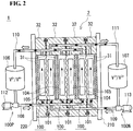
Figure 2 is a schematic configuration view of a redox flow battery according toEmbodiment 1. -
Figure 3 is a schematic configuration view of a cell stack according toEmbodiment 1. -
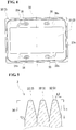
Figure 4 is a plan view of a cell frame according toEmbodiment 1. -
Figure 5 is a partial longitudinal sectional view of a cell stack according toEmbodiment 1. -
Figure 6 is a partial longitudinal sectional view of a cell stack according toEmbodiment 2. -
Figure 7 is a partial longitudinal sectional view of a cell stack according toEmbodiment 3. -
Figure 8 is a partial longitudinal sectional view of a cell stack according to Embodiment 4. -
Figure 9 is a partial longitudinal sectional view of a cell stack according to Embodiment 5. -
Figure 10 is a partial longitudinal sectional view of a cell stack according to Embodiment 6. -
Figure 11 is a plan view of a cell frame according to Embodiment 7. -
Figure 12 is a plan view of a cell frame according to Embodiment 8. -
Figure 13 is a plan view of a cell frame according to Embodiment 9. Description of Embodiments - The frame body of an existing cell frame has a rectangular shape in a section taken in the thickness direction of the outer peripheral portion of the frame body viewed in plan. As a result, for example, when plural cell frames are stacked and when the plural cell frames stacked are fastened, a corner portion constituting the outer edge of the frame body of one of adjacent cell frames may damage the frame body of the other cell frame. Since cell frames of a cell stack are often produced by injection molding of injecting resin into a mold, cell frames may break due to such damage caused by corner portions.
- Accordingly, an object of the present disclosure is to provide a frame body and a cell frame that are less likely to be damaged during stacking or during fastening. Another object of the present disclosure is to provide a cell stack in which stacked cell frames are less likely to be damaged. Still another object of the present disclosure is to provide a redox flow battery including a cell stack in which cell frames are less likely to be damaged.
- A frame body and a cell frame according to the present disclosure are less likely to be damaged during stacking. In a cell stack and a redox flow battery according to the present disclosure, the frame bodies of cell frames constituting the cell stack and the redox flow battery are less likely to be damaged.
- Features of embodiments according to the invention of the present application will be first listed and described.
- <1> A frame body according to an embodiment is
a frame body for a cell frame of a redox flow battery,
the frame body including an outer peripheral portion,
the outer peripheral portion including a thin region whose thickness gradually decreases in a direction from a center of the frame body toward an outer periphery of the frame body.
The frame body having such a configuration enables, during stacking of plural cell frames or during fastening of the stacked cell frames, suppression of contact between a portion constituting the outer edge of the frame body of one of adjacent cell frames, and the frame body of the other cell frame, to thereby suppress damaging to the other cell frame. This enables avoidance of problems due to the damaged frame body of a cell frame, for example, a problem of leakage of an electrolyte from between adjacent cell frames. Incidentally, the thin region may be formed along the whole periphery of the outer peripheral portion, or the thin region may be formed in a portion of the outer peripheral portion. - <2> The frame body according to the embodiment may have a configuration in which,
in a section taken along a plane passing through the center of the frame body and extending in a thickness direction of the frame body, the thin region has a sectional shape that is a pencil-down shape.
The thin region is formed so as to have a sectional shape that is a pencil-down shape, which enables effective suppression of contact between a portion constituting the outer edge of the frame body of one of adjacent cell frames, and the frame body of the other cell frame, to thereby effectively suppress damaging to the other cell frame. - <3> The frame body according to the embodiment may have a configuration in which,
in a section taken along a plane passing through the center of the frame body and extending in a thickness direction of the frame body, the thin region has a sectional shape that is a rectangular shape having rounded corner portions.
The thin region is formed so as to have a sectional shape that is a rectangular shape having rounded corner portions, which enables effective suppression of contact between a portion constituting the outer edge of the frame body of one of adjacent cell frames, and the frame body of the other cell frame, to thereby effectively suppress damaging to the other cell frame. - <4> The frame body according to the embodiment may have a configuration in which,
in a section taken along a plane passing through the center of the frame body and extending in a thickness direction of the frame body, the thin region has a sectional shape that is a rectangular shape having C-chamfered corner portions.
The thin region is formed so as to have a sectional shape that is a rectangular shape having C-chamfered corner portions, which enables effective suppression of contact between a portion constituting the outer edge of the frame body of one of adjacent cell frames, and the frame body of the other cell frame, to thereby effectively suppress damaging to the other cell frame. - <5> The frame body according to the embodiment may have a configuration in which,
in a section taken along a plane passing through the center of the frame body and extending in a thickness direction of the frame body, the thin region has a sectional shape that is solely constituted by a curve.
At least a portion of the outer peripheral portion is rounded, which enables effective suppression of contact between a portion constituting the outer edge of the frame body of one of adjacent cell frames, and the frame body of the other cell frame, to thereby effectively suppress damaging to the other cell frame. - <6> A cell frame according to an embodiment includes
the frame body according to the embodiment, and a bipolar plate supported by the frame body.
The cell frame having such a configuration enables, during stacking of plural cell frames or during fastening of the stacked cell frames, suppression of contact between a portion constituting the outer edge of the frame body of one of adjacent cell frames, and the frame body of the other cell frame, to thereby suppress damaging to the other cell frame. This enables avoidance of problems due to the damaged frame body of a cell frame, for example, a problem of leakage of an electrolyte from between adjacent cell frames. - <7> A cell stack according to an embodiment includes
the cell frame according to the embodiment.
In the cell stack according to the embodiment, stacked cell frames serving as one of the constituent elements are less likely to be damaged. This enables avoidance of problems due to a damaged cell frame, for example, a problem of leakage of an electrolyte from between adjacent cell frames when the cell stack according to the embodiment is used to constitute a redox flow battery. - <8> A redox flow battery according to an embodiment includes
the cell stack according to the embodiment. - The redox flow battery according to the embodiment is a redox flow battery including a cell stack in which cell frames are less likely to be damaged. As a result, the redox flow battery according to the embodiment is a redox flow battery that enables avoidance of problems due to a damaged cell frame, for example, a problem of leakage of an electrolyte from between adjacent cell frames.
- Hereinafter, redox flow batteries (RF batteries) according to embodiments will be described. However, the present invention is not limited to the configurations illustrated in the embodiments. The present invention is defined by Claims and is intended to embrace all the modifications within the meaning and range of equivalency of the Claims.
- An RF battery according to
Embodiment 1 will be described on the basis ofFig. 1 to Fig. 5 . - The RF battery is one of electrolyte-circulation storage batteries, and is used for storage of electricity of new energy from solar photovoltaic power generation and wind power generation. As illustrated in
Fig. 1 , which illustrates the principle of operations of anRF battery 1, theRF battery 1 is a battery configured to be charged and discharged by means of the difference between the oxidation-reduction potential of active material ions contained in a positive electrode electrolyte, and the oxidation-reduction potential of active material ions contained in a negative electrode electrolyte. TheRF battery 1 includes acell 100, which is divided, by amembrane 101 permeable to hydrogen ions, into apositive electrode cell 102 and anegative electrode cell 103. - The
positive electrode cell 102 includes apositive electrode 104 therein; and, to thepositive electrode cell 102, a positiveelectrode electrolyte tank 106 storing a positive electrode electrolyte is connected viaducts duct 108 is equipped with apump 112. Thesemembers electrode circulation mechanism 100P configured to circulate the positive electrode electrolyte. Similarly, thenegative electrode cell 103 includes anegative electrode 105 therein; and, to thenegative electrode cell 103, a negativeelectrode electrolyte tank 107 storing a negative electrode electrolyte is connected viaducts duct 109 is equipped with apump 113. Thesemembers electrode circulation mechanism 100N configured to circulate the negative electrode electrolyte. The electrolytes stored in thetanks cells pumps pumps - The
cell 100 is normally formed within a structure referred to as acell stack 2, which is illustrated inFig. 2 andFig. 3 . Thecell stack 2 is constituted by sandwiching a stack structure referred to as a substack 200 (Fig. 3 ), from its both sides by twoend plates substack 200 with a fastening mechanism 230 (in the configuration provided as an example inFig. 3 ,plural substacks 200 are used). - Such a substack 200 (
Fig. 3 ) has a configuration in which thecell frame 3, thepositive electrode 104, themembrane 101, thenegative electrode 105, and thecell frame 3 are repeatedly stacked, and the stack body is sandwiched between supply/drainage plates 190 and 190 (refer to the lower drawing inFig. 3 ; omitted inFig. 2 ). Such acell frame 3 includes aframe body 32 having a through window and abipolar plate 31, which covers the through window. Thepositive electrode 104 is disposed so as to be in contact with one of the surfaces of thebipolar plate 31, and thenegative electrode 105 is disposed so as to be in contact with the other surface of thebipolar plate 31. In this configuration, asingle cell 100 is formed between thebipolar plates 31 of adjacent cell frames 3. - Supply and drainage of electrolytes through the supply/
drainage plates cell 100 are performed withliquid supply manifolds liquid drainage manifolds cell frame 3. The positive electrode electrolyte is supplied through theliquid supply manifold 33, then through an inlet slit formed in one surface of the cell frame 3 (the surface illustrated as being exposed in the drawing), to thepositive electrode 104; and the positive electrode electrolyte is drained through an outlet slit formed in an upper portion of thecell frame 3 to theliquid drainage manifold 35. Similarly, the negative electrode electrolyte is supplied through theliquid supply manifold 34, then through an inlet slit (represented by broken lines) formed in the other surface of the cell frame 3 (the surface illustrated as being hidden in the drawing), to thenegative electrode 105; and the negative electrode electrolyte is drained through an outlet slit (represented by broken lines) formed in an upper portion of thecell frame 3 to theliquid drainage manifold 36. Loop-shapedsealing members 37 such as O-rings or flat gaskets are individually disposed between the cell frames 3 to suppress leakage of electrolytes from thesubstack 200. - The
frame body 32 of thecell frame 3 is an injection-molded body produced by injection molding. Whensuch frame bodies 32 have an outer-periphery sectional shape that is rectangular and plural cell frames 3 are stacked, a corner portion of the rectangle constituting the outer edge of theframe body 32 of one of adjacent cell frames 3 may come into contact with theframe body 32 of theother cell frame 3 and may damage theframe body 32 of theother cell frame 3. When theframe body 32 of such acell frame 3 is damaged, for example, broken, problems such as leakage of an electrolyte from thecell stack 2 may occur. - In order to address such problems, the
RF battery 1 of this example is provided such that the cell frames 3 in thecell stack 2 have a thin region. The thin region will be described in detail on the basis ofFig. 4 and Fig. 5 . -
Figure 4 is a plan view of thecell frame 3 according toEmbodiment 1. In this example, a direction in which the liquid supply manifold 33 (34) and the liquid drainage manifold 36 (35) are separated from each other, that is, the vertical direction in the drawing ofFig. 4 , is the length direction of theframe body 32; a direction in which theliquid supply manifold 33 and theliquid supply manifold 34 are separated from each other, that is, the horizontal direction in the drawing, is the width direction of theframe body 32; and the depth direction in the drawing is the thickness direction of theframe body 32. A sealinggroove 37s, which surrounds the outer periphery of themanifolds 33 to 36 of thecell frame 3, is a groove into which the sealingmember 37 inFig. 3 is inserted. Incidentally,Fig. 4 illustrates mere examples and does not particularly place limitations in terms of the shapes and positions of themanifolds 33 to 36 and the shapes and arrangements of the inlet slits and the outlet slits extending from themanifolds 33 to 36 to thebipolar plate 31. - In
Fig. 4 , theframe body 32 of thecell frame 3 according to this embodiment includes a thin region 30 (region on the outer-edge side beyond the double dot-dashed line), which has, in plan view, a predetermined width from the outer edge toward the inside.
Thethin region 30 is a region whose thickness gradually decreases from its formation start position (the position marked with the double dot-dashed line) on the center side of thecell frame 3, toward the outer edge. The width of thethin region 30, that is, the distance from the position marked with the double dot-dashed line to the outer edge, is preferably 0.1 mm or more and 100 mm or less, more preferably 1 mm or more and 80 mm or less, or 5 mm or more and 50 mm or less. - Such
thin regions 30 provided in theframe bodies 32 of cell frames 3 enable, during stacking of the plural cell frames 3 or during fastening of the stacked cell frames 3, suppression of contact between a portion constituting the outer edge of theframe body 32 of one of adjacent cell frames 3, and theframe body 32 of theother cell frame 3, to thereby suppress damaging to theother cell frame 3. This enables avoidance of problems due to the damagedframe body 32 of acell frame 3, for example, a problem of leakage of an electrolyte from between adjacent cell frames 3. - The sectional shape of the
thin region 30 in the thickness direction of thecell frame 3 is not particularly limited as long as the thickness of the sectional shape gradually decreases toward the outer edge. An example of the sectional shape of thethin region 30 will be described on the basis ofFig. 5. Figure 5 illustrates a portion of a section taken along a line represented by the single dot-dashed line inFig. 4 (a portion of a section passing through the center of theframe body 32 and extending in the thickness direction of the frame body 32). - In the example illustrated in
Fig. 5 , thethin region 30 is formed so as to have a sectional shape that is a pencil-down shape. The pencil-down shape is a tapered shape that is similar to the tip portion of a pencil. In this example, the tip of the pencil-down shape is rounded. Thus, a length L1, in a direction along the flat surfaces of thecell frame 3, from a formation start position to an outer edge of thethin region 30, is larger than a length L2, in the thickness direction of thecell frame 3, from a formation start position to an outer edge of thethin region 30. The length L1 is not particularly limited as long as it is at least 5 mm shorter than the length from the outer edge to the sealinggroove 37s inFig. 4 . For example, the length L1 is preferably 1 mm or more and 30 mm or less, more preferably 5 mm or more and 10 mm or less. The length L2 is not particularly limited as long as it is 1/2 or less of the thickness of thecell frame 3. For example, the length L2 is preferably 0.1 mm or more and 2.5 mm or less, more preferably 1 mm or more and 1.5 mm or less. - In the configuration of this example, the boundary portions (refer to the white arrow) between the
thin region 30 and the flat surface portions are preferably provided so as to have curved surfaces (curves in the section). The boundary portions are provided so as to have curved surfaces, which enables suppression of damaging by a boundary portion of one of adjacent cell frames 3 to theother cell frame 3. - In
Embodiment 2, the configuration of acell stack 2 including cell frames 3 having athin region 30 having a sectional shape different from that inEmbodiment 1 will be described on the basis ofFig. 6 . The same configuration as inEmbodiment 1 may be employed except for the sectional shape of thethin region 30. - In the example illustrated in
Fig. 6 , thethin region 30 is formed so as to have a sectional shape in which corner portions (refer to the dotted lines) of the rectangle are rounded. The value of a rounding radius R is not particularly limited as long as it is 1/2 or less of the thickness of thecell frame 3. For example, the rounding radius R is preferably 0.1 mm or more and 2.5 mm or less, more preferably 1.0 mm or more and 1.5 mm or less. - In
Embodiment 3, the configuration of acell stack 2 including cell frames 3 having athin region 30 having a sectional shape different from the sectional shapes inEmbodiments Fig. 7 . The same configuration as inEmbodiment 1 may be employed except for the sectional shape of thethin region 30. - In the example illustrated in
Fig. 7 , thethin region 30 is formed so as to have a sectional shape in which corner portions (refer to the dotted lines) of the rectangle are C-chamfered. The value of a chamfering length C is not particularly limited as long as it is 1/2 or less of the thickness of thecell frame 3. For example, the chamfering length C is preferably 0.1 mm or more and 2.5 mm or less, more preferably 1.0 mm or more and 1.5 mm or less. - In the configuration of this example, the boundary portions (refer to the white arrow) between the
thin region 30 and the flat surface portions are preferably provided so as to have curved surfaces (curves in the section). The boundary portions are provided so as to have curved surfaces, which enables suppression of damaging by a boundary portion of one of adjacent cell frames 3 to theother cell frame 3. - In Embodiment 4, a
cell stack 2 including cell frames 3 having athin region 30 having a sectional shape solely constituted by a curve will be described on the basis ofFig. 8 . - In the example illustrated in
Fig. 8 , thethin region 30 is formed so as to have a sectional shape that is a semicircular (that is, curved) shape. Such a configuration also enables suppression of damaging by a boundary portion of one of adjacent cell frames 3 to theother cell frame 3. - Incidentally, the sectional shape of the
thin region 30 is not limited to a semicircular shape as long as the sectional shape is solely constituted by a curve. For example, the sectional shape may be a semi-elliptical shape, or may be a shape in which the linear portions of the pencil-down shape inFig. 5 are rounded. - In Embodiment 5, the configuration of a
cell stack 2 including cell frames 3 having athin region 30 having a sectional shape different from the sectional shapes inEmbodiments 1 to 4 will be described on the basis ofFig. 9 . - In the example illustrated in
Fig. 9 , thethin region 30 is formed so as to have, in the thickness direction, inclination of only one surface of the outer peripheral portion of theframe body 32 of such acell frame 3. Thus, thethin region 30 is formed so as to have a sectional shape that is a trapezoidal shape. Such a configuration also enables suppression of damaging in adjacent cell frames 3. - In
Embodiments 1 to 5, the widths of thethin regions 30 formed (lengths from the formation start positions to the outer edges of the thin regions 30) are the same. In Embodiment 6, an example in which cell frames 3 have different widths ofthin regions 30 formed will be described on the basis ofFig. 10 . - As illustrated in
Fig. 10 , between adjacent cell frames 3, the widths of thethin regions 30 formed are different. This enables suppression of damaging in adjacent cell frames 3. In this example, the cell frames 3 on the left and on the right havethin regions 30 having a C-chamfered shape, and thecell frame 3 in the middle has athin region 30 having a pencil-down shape; however, this combination places no limitations on the combination of cell frames 3. Cell frames 3 according toEmbodiments 1 to 5 may be appropriately combined to constitute acell stack 2. - The shape of the
cell frame 3 is not limited to the shape inFig. 4 , and may be, for example, the shape illustrated inFig. 11 . - In the
cell frame 3 inFig. 11 ,slits frame body 32 substantially have a J-shape. Specifically, the slits extend outwardly from positions on the lateral side surfaces of thebipolar plate 31, and then bend inwardly and individually join themanifolds - In such cell frames 3 having the shape, formation of
thin regions 30 according toEmbodiments 1 to 6 also enables suppression of damaging to theframe bodies 32. - Alternatively, the
cell frame 3 may be provided so as to have the shape illustrated inFig. 12 . In thecell frame 3 inFig. 12 ,slits frame body 32 intricately bend in the vertical direction and in the horizontal direction and respectively join themanifolds - In such cell frames 3 having the shape, formation of
thin regions 30 according toEmbodiments 1 to 6 also enables suppression of damaging to theframe bodies 32. - Alternatively, the
cell frame 3 may be provided so as to have the shape illustrated inFig. 13 . Thecell frame 3 inFig. 13 has no slits extending from themanifolds bipolar plate 31. Instead, slits are formed in agasket 39 disposed between adjacent cell frames 3. Thegasket 39 inFig. 13 is agasket 39 that is disposed on a surface (that is illustrated as being exposed in the drawing) of thecell frame 3. Thisgasket 39 includesmanifolds inlet slit 33s, which has a cutout shape and joins the manifold 33; and anoutlet slit 35s, which has a cutout shape and joins the manifold 35. Incidentally, a gasket 39 (not shown) that is disposed on a surface (that is illustrated as being hidden in the drawing) of thecell frame 3, includesmanifolds inlet slit 34s, which has a cutout shape and joins the manifold 34; and anoutlet slit 36s, which has a cutout shape and joins the manifold 36. - In such cell frames 3 having the shape, formation of
thin regions 30 according toEmbodiments 1 to 6 also enables suppression of damaging to theframe bodies 32. -
Embodiments 1 to 9 described each relate to acell frame 3 in which a length of theframe body 32 in the width direction (the horizontal direction in the drawing) is larger than a length of theframe body 32 in the length direction (the vertical direction in the drawing). Alternatively, a cell frame may also be provided so as to have a larger size in the length direction than in the width direction. - Alternatively, a cell frame may also be provided so as to have the same length in the length direction and in the width direction.
-
- 1 RF battery (redox flow battery)
- 2 cell stack (cell stack)
- 3 cell frame
- 30 thin region; 31 bipolar plate; 32 frame body
- 33 and 34 liquid supply manifolds; 35 and 36 liquid drainage manifolds
- 33s and 34s inlet slits; 35s and 36s outlet slits
- 37 sealing member; 37s sealing groove
- 39 gasket
- 100 cell; 101 membrane; 102 positive electrode cell; 103 negative electrode cell
- 100P positive electrode circulation mechanism; 100N negative electrode circulation mechanism
- 104 positive electrode; 105 negative electrode; 106 positive electrode electrolyte tank
- 107 negative electrode electrolyte tank; 108, 109, 110, and 111 ducts
- 112 and 113 pumps
- 190 supply/drainage plate; 200 substack
- 210 and 220 end plates
- 230 fastening mechanism
Claims (8)
- A frame body for a cell frame of a redox flow battery,
the frame body comprising an outer peripheral portion,
the outer peripheral portion including a thin region whose thickness gradually decreases in a direction from a center of the frame body toward an outer periphery of the frame body. - The frame body according to Claim 1, wherein, in a section taken along a plane passing through the center of the frame body and extending in a thickness direction of the frame body, the thin region has a sectional shape that is a pencil-down shape.
- The frame body according to Claim 1, wherein, in a section taken along a plane passing through the center of the frame body and extending in a thickness direction of the frame body, the thin region has a sectional shape that is a rectangular shape having rounded corner portions.
- The frame body according to Claim 1, wherein, in a section taken along a plane passing through the center of the frame body and extending in a thickness direction of the frame body, the thin region has a sectional shape that is a rectangular shape having C-chamfered corner portions.
- The frame body according to Claim 1, wherein, in a section taken along a plane passing through the center of the frame body and extending in a thickness direction of the frame body, the thin region has a sectional shape that is solely constituted by a curve.
- A cell frame comprising the frame body according to any one of Claim 1 to Claim 5, and a bipolar plate supported by the frame body.
- A cell stack comprising the cell frame according to Claim 6.
- A redox flow battery comprising the cell stack according to Claim 7.
Applications Claiming Priority (1)
| Application Number | Priority Date | Filing Date | Title |
|---|---|---|---|
| PCT/JP2016/079679 WO2018066094A1 (en) | 2016-10-05 | 2016-10-05 | Frame body, cell frame, cell stack, and redox flow battery |
Publications (3)
| Publication Number | Publication Date |
|---|---|
| EP3525275A1 true EP3525275A1 (en) | 2019-08-14 |
| EP3525275A4 EP3525275A4 (en) | 2019-11-06 |
| EP3525275B1 EP3525275B1 (en) | 2022-08-31 |
Family
ID=59814696
Family Applications (1)
| Application Number | Title | Priority Date | Filing Date |
|---|---|---|---|
| EP16913642.1A Active EP3525275B1 (en) | 2016-10-05 | 2016-10-05 | Frame body, cell frame, cell stack, and redox flow battery |
Country Status (9)
| Country | Link |
|---|---|
| US (1) | US10431843B2 (en) |
| EP (1) | EP3525275B1 (en) |
| JP (1) | JP6731167B2 (en) |
| KR (1) | KR20190055013A (en) |
| CN (2) | CN107919486B (en) |
| AU (1) | AU2016420290B2 (en) |
| DE (1) | DE202017104643U1 (en) |
| TW (1) | TWI731132B (en) |
| WO (1) | WO2018066094A1 (en) |
Families Citing this family (1)
| Publication number | Priority date | Publication date | Assignee | Title |
|---|---|---|---|---|
| WO2025154350A1 (en) * | 2024-01-19 | 2025-07-24 | 住友電気工業株式会社 | Frame body, cell frame, battery cell, cell stack, and redox flow battery system |
Family Cites Families (11)
| Publication number | Priority date | Publication date | Assignee | Title |
|---|---|---|---|---|
| US5508131A (en) * | 1994-04-07 | 1996-04-16 | Globe-Union Inc. | Injection molded battery containment for bipolar batteries |
| DE4442285C1 (en) * | 1994-11-28 | 1996-02-08 | Siemens Ag | Stack of fuel cells with frame around electrodes and membranes for electric vehicle drive fuel-cell battery |
| CN2727974Y (en) * | 2003-07-18 | 2005-09-21 | 中南大学 | Frame for redox flow battery assembly |
| JP2006324117A (en) * | 2005-05-18 | 2006-11-30 | Sumitomo Electric Ind Ltd | Electrolyte circulating battery |
| GB0913836D0 (en) * | 2009-08-07 | 2009-09-16 | Afc Energy Plc | Fuel cell |
| JP5732241B2 (en) * | 2010-12-03 | 2015-06-10 | Udトラックス株式会社 | Power storage cell, power storage device, and vehicle equipped with power storage device |
| JP5477672B2 (en) | 2011-03-31 | 2014-04-23 | 住友電気工業株式会社 | Cell frame for electrolyte flow type battery, cell stack for electrolyte flow type battery, and electrolyte flow type battery |
| FR2996361B1 (en) * | 2012-10-03 | 2017-02-17 | Air Liquide | SEALING DEVICE FOR FUEL CELL, CELL AND FUEL CELL COMPRISING SUCH A DEVICE |
| JP6478284B2 (en) | 2013-06-06 | 2019-03-06 | Necエナジーデバイス株式会社 | Battery module |
| JP6098998B2 (en) | 2013-09-12 | 2017-03-22 | 住友電気工業株式会社 | Battery cell stack and redox flow battery |
| US20150125768A1 (en) * | 2013-11-07 | 2015-05-07 | Enervault Corporation | Cell and Cell Block Configurations for Redox Flow Battery Systems |
-
2016
- 2016-10-05 EP EP16913642.1A patent/EP3525275B1/en active Active
- 2016-10-05 US US15/549,109 patent/US10431843B2/en active Active
- 2016-10-05 AU AU2016420290A patent/AU2016420290B2/en active Active
- 2016-10-05 WO PCT/JP2016/079679 patent/WO2018066094A1/en not_active Ceased
- 2016-10-05 JP JP2018505483A patent/JP6731167B2/en active Active
- 2016-10-05 KR KR1020187006360A patent/KR20190055013A/en not_active Withdrawn
-
2017
- 2017-08-01 TW TW106125827A patent/TWI731132B/en active
- 2017-08-03 DE DE202017104643.5U patent/DE202017104643U1/en not_active Expired - Lifetime
- 2017-09-28 CN CN201710895787.6A patent/CN107919486B/en active Active
- 2017-09-28 CN CN201721263081.XU patent/CN208336385U/en not_active Expired - Fee Related
Also Published As
| Publication number | Publication date |
|---|---|
| US10431843B2 (en) | 2019-10-01 |
| EP3525275A4 (en) | 2019-11-06 |
| KR20190055013A (en) | 2019-05-22 |
| WO2018066094A1 (en) | 2018-04-12 |
| CN208336385U (en) | 2019-01-04 |
| US20180248216A1 (en) | 2018-08-30 |
| AU2016420290A1 (en) | 2018-04-19 |
| CN107919486B (en) | 2021-07-13 |
| DE202017104643U1 (en) | 2017-08-21 |
| AU2016420290B2 (en) | 2022-06-02 |
| TW201814951A (en) | 2018-04-16 |
| JPWO2018066094A1 (en) | 2019-07-18 |
| TWI731132B (en) | 2021-06-21 |
| EP3525275B1 (en) | 2022-08-31 |
| CN107919486A (en) | 2018-04-17 |
| JP6731167B2 (en) | 2020-07-29 |
Similar Documents
| Publication | Publication Date | Title |
|---|---|---|
| EP3113272B1 (en) | Frame body, cell frame for redox flow battery, and redox flow battery | |
| EP3528327B1 (en) | Bipolar plate, cell frame, cell stack, and redox flow cell | |
| US10566644B2 (en) | Battery cell and redox flow battery | |
| EP3217461A1 (en) | Galvanic cell and redox flow cell | |
| CN107919487B (en) | Frame bodies, cell frames, cell stacks, and redox flow batteries | |
| EP3217459B1 (en) | Electrolyte-circulation battery | |
| JP6836723B2 (en) | Cell frame, cell stack, and redox flow batteries | |
| EP3553863B1 (en) | Redox flow battery | |
| TW202002377A (en) | Bipolar plate, cell frame, cell stack, and redox flow battery | |
| JP6765642B2 (en) | Bipolar plate, cell frame, cell stack, and redox flow battery | |
| JP2017010791A (en) | Cell frame, cell stack and redox flow cell | |
| EP3525275A1 (en) | Frame body, cell frame, cell stack, and redox flow battery | |
| JP7101771B2 (en) | Bipolar plate, cell frame, cell stack, and redox flow battery | |
| WO2018066093A1 (en) | Cell stack and redox flow battery |
Legal Events
| Date | Code | Title | Description |
|---|---|---|---|
| STAA | Information on the status of an ep patent application or granted ep patent |
Free format text: STATUS: UNKNOWN |
|
| STAA | Information on the status of an ep patent application or granted ep patent |
Free format text: STATUS: THE INTERNATIONAL PUBLICATION HAS BEEN MADE |
|
| PUAI | Public reference made under article 153(3) epc to a published international application that has entered the european phase |
Free format text: ORIGINAL CODE: 0009012 |
|
| STAA | Information on the status of an ep patent application or granted ep patent |
Free format text: STATUS: REQUEST FOR EXAMINATION WAS MADE |
|
| 17P | Request for examination filed |
Effective date: 20180302 |
|
| AK | Designated contracting states |
Kind code of ref document: A1 Designated state(s): AL AT BE BG CH CY CZ DE DK EE ES FI FR GB GR HR HU IE IS IT LI LT LU LV MC MK MT NL NO PL PT RO RS SE SI SK SM TR |
|
| AX | Request for extension of the european patent |
Extension state: BA ME |
|
| A4 | Supplementary search report drawn up and despatched |
Effective date: 20191007 |
|
| RIC1 | Information provided on ipc code assigned before grant |
Ipc: H01M 8/18 20060101AFI20190930BHEP Ipc: H01M 8/02 20160101ALI20190930BHEP |
|
| DAV | Request for validation of the european patent (deleted) | ||
| DAX | Request for extension of the european patent (deleted) | ||
| GRAP | Despatch of communication of intention to grant a patent |
Free format text: ORIGINAL CODE: EPIDOSNIGR1 |
|
| STAA | Information on the status of an ep patent application or granted ep patent |
Free format text: STATUS: GRANT OF PATENT IS INTENDED |
|
| INTG | Intention to grant announced |
Effective date: 20220530 |
|
| GRAS | Grant fee paid |
Free format text: ORIGINAL CODE: EPIDOSNIGR3 |
|
| GRAA | (expected) grant |
Free format text: ORIGINAL CODE: 0009210 |
|
| STAA | Information on the status of an ep patent application or granted ep patent |
Free format text: STATUS: THE PATENT HAS BEEN GRANTED |
|
| AK | Designated contracting states |
Kind code of ref document: B1 Designated state(s): AL AT BE BG CH CY CZ DE DK EE ES FI FR GB GR HR HU IE IS IT LI LT LU LV MC MK MT NL NO PL PT RO RS SE SI SK SM TR |
|
| REG | Reference to a national code |
Ref country code: CH Ref legal event code: EP Ref country code: GB Ref legal event code: FG4D |
|
| REG | Reference to a national code |
Ref country code: AT Ref legal event code: REF Ref document number: 1515956 Country of ref document: AT Kind code of ref document: T Effective date: 20220915 Ref country code: DE Ref legal event code: R096 Ref document number: 602016074749 Country of ref document: DE |
|
| REG | Reference to a national code |
Ref country code: IE Ref legal event code: FG4D |
|
| REG | Reference to a national code |
Ref country code: LT Ref legal event code: MG9D |
|
| REG | Reference to a national code |
Ref country code: NL Ref legal event code: MP Effective date: 20220831 |
|
| PG25 | Lapsed in a contracting state [announced via postgrant information from national office to epo] |
Ref country code: SE Free format text: LAPSE BECAUSE OF FAILURE TO SUBMIT A TRANSLATION OF THE DESCRIPTION OR TO PAY THE FEE WITHIN THE PRESCRIBED TIME-LIMIT Effective date: 20220831 Ref country code: RS Free format text: LAPSE BECAUSE OF FAILURE TO SUBMIT A TRANSLATION OF THE DESCRIPTION OR TO PAY THE FEE WITHIN THE PRESCRIBED TIME-LIMIT Effective date: 20220831 Ref country code: NO Free format text: LAPSE BECAUSE OF FAILURE TO SUBMIT A TRANSLATION OF THE DESCRIPTION OR TO PAY THE FEE WITHIN THE PRESCRIBED TIME-LIMIT Effective date: 20221130 Ref country code: LV Free format text: LAPSE BECAUSE OF FAILURE TO SUBMIT A TRANSLATION OF THE DESCRIPTION OR TO PAY THE FEE WITHIN THE PRESCRIBED TIME-LIMIT Effective date: 20220831 Ref country code: LT Free format text: LAPSE BECAUSE OF FAILURE TO SUBMIT A TRANSLATION OF THE DESCRIPTION OR TO PAY THE FEE WITHIN THE PRESCRIBED TIME-LIMIT Effective date: 20220831 Ref country code: FI Free format text: LAPSE BECAUSE OF FAILURE TO SUBMIT A TRANSLATION OF THE DESCRIPTION OR TO PAY THE FEE WITHIN THE PRESCRIBED TIME-LIMIT Effective date: 20220831 |
|
| PG25 | Lapsed in a contracting state [announced via postgrant information from national office to epo] |
Ref country code: PL Free format text: LAPSE BECAUSE OF FAILURE TO SUBMIT A TRANSLATION OF THE DESCRIPTION OR TO PAY THE FEE WITHIN THE PRESCRIBED TIME-LIMIT Effective date: 20220831 Ref country code: IS Free format text: LAPSE BECAUSE OF FAILURE TO SUBMIT A TRANSLATION OF THE DESCRIPTION OR TO PAY THE FEE WITHIN THE PRESCRIBED TIME-LIMIT Effective date: 20221231 Ref country code: HR Free format text: LAPSE BECAUSE OF FAILURE TO SUBMIT A TRANSLATION OF THE DESCRIPTION OR TO PAY THE FEE WITHIN THE PRESCRIBED TIME-LIMIT Effective date: 20220831 Ref country code: GR Free format text: LAPSE BECAUSE OF FAILURE TO SUBMIT A TRANSLATION OF THE DESCRIPTION OR TO PAY THE FEE WITHIN THE PRESCRIBED TIME-LIMIT Effective date: 20221201 |
|
| PG25 | Lapsed in a contracting state [announced via postgrant information from national office to epo] |
Ref country code: SM Free format text: LAPSE BECAUSE OF FAILURE TO SUBMIT A TRANSLATION OF THE DESCRIPTION OR TO PAY THE FEE WITHIN THE PRESCRIBED TIME-LIMIT Effective date: 20220831 Ref country code: RO Free format text: LAPSE BECAUSE OF FAILURE TO SUBMIT A TRANSLATION OF THE DESCRIPTION OR TO PAY THE FEE WITHIN THE PRESCRIBED TIME-LIMIT Effective date: 20220831 Ref country code: PT Free format text: LAPSE BECAUSE OF FAILURE TO SUBMIT A TRANSLATION OF THE DESCRIPTION OR TO PAY THE FEE WITHIN THE PRESCRIBED TIME-LIMIT Effective date: 20230102 Ref country code: ES Free format text: LAPSE BECAUSE OF FAILURE TO SUBMIT A TRANSLATION OF THE DESCRIPTION OR TO PAY THE FEE WITHIN THE PRESCRIBED TIME-LIMIT Effective date: 20220831 Ref country code: DK Free format text: LAPSE BECAUSE OF FAILURE TO SUBMIT A TRANSLATION OF THE DESCRIPTION OR TO PAY THE FEE WITHIN THE PRESCRIBED TIME-LIMIT Effective date: 20220831 Ref country code: CZ Free format text: LAPSE BECAUSE OF FAILURE TO SUBMIT A TRANSLATION OF THE DESCRIPTION OR TO PAY THE FEE WITHIN THE PRESCRIBED TIME-LIMIT Effective date: 20220831 |
|
| PG25 | Lapsed in a contracting state [announced via postgrant information from national office to epo] |
Ref country code: SK Free format text: LAPSE BECAUSE OF FAILURE TO SUBMIT A TRANSLATION OF THE DESCRIPTION OR TO PAY THE FEE WITHIN THE PRESCRIBED TIME-LIMIT Effective date: 20220831 Ref country code: MC Free format text: LAPSE BECAUSE OF FAILURE TO SUBMIT A TRANSLATION OF THE DESCRIPTION OR TO PAY THE FEE WITHIN THE PRESCRIBED TIME-LIMIT Effective date: 20220831 Ref country code: EE Free format text: LAPSE BECAUSE OF FAILURE TO SUBMIT A TRANSLATION OF THE DESCRIPTION OR TO PAY THE FEE WITHIN THE PRESCRIBED TIME-LIMIT Effective date: 20220831 |
|
| REG | Reference to a national code |
Ref country code: CH Ref legal event code: PL |
|
| REG | Reference to a national code |
Ref country code: DE Ref legal event code: R097 Ref document number: 602016074749 Country of ref document: DE |
|
| P01 | Opt-out of the competence of the unified patent court (upc) registered |
Effective date: 20230515 |
|
| REG | Reference to a national code |
Ref country code: BE Ref legal event code: MM Effective date: 20221031 |
|
| PG25 | Lapsed in a contracting state [announced via postgrant information from national office to epo] |
Ref country code: NL Free format text: LAPSE BECAUSE OF FAILURE TO SUBMIT A TRANSLATION OF THE DESCRIPTION OR TO PAY THE FEE WITHIN THE PRESCRIBED TIME-LIMIT Effective date: 20220831 Ref country code: LU Free format text: LAPSE BECAUSE OF NON-PAYMENT OF DUE FEES Effective date: 20221005 Ref country code: AL Free format text: LAPSE BECAUSE OF FAILURE TO SUBMIT A TRANSLATION OF THE DESCRIPTION OR TO PAY THE FEE WITHIN THE PRESCRIBED TIME-LIMIT Effective date: 20220831 |
|
| PLBE | No opposition filed within time limit |
Free format text: ORIGINAL CODE: 0009261 |
|
| STAA | Information on the status of an ep patent application or granted ep patent |
Free format text: STATUS: NO OPPOSITION FILED WITHIN TIME LIMIT |
|
| PG25 | Lapsed in a contracting state [announced via postgrant information from national office to epo] |
Ref country code: LI Free format text: LAPSE BECAUSE OF NON-PAYMENT OF DUE FEES Effective date: 20221031 Ref country code: FR Free format text: LAPSE BECAUSE OF NON-PAYMENT OF DUE FEES Effective date: 20221031 Ref country code: CH Free format text: LAPSE BECAUSE OF NON-PAYMENT OF DUE FEES Effective date: 20221031 |
|
| 26N | No opposition filed |
Effective date: 20230601 |
|
| PG25 | Lapsed in a contracting state [announced via postgrant information from national office to epo] |
Ref country code: SI Free format text: LAPSE BECAUSE OF FAILURE TO SUBMIT A TRANSLATION OF THE DESCRIPTION OR TO PAY THE FEE WITHIN THE PRESCRIBED TIME-LIMIT Effective date: 20220831 |
|
| PG25 | Lapsed in a contracting state [announced via postgrant information from national office to epo] |
Ref country code: BE Free format text: LAPSE BECAUSE OF NON-PAYMENT OF DUE FEES Effective date: 20221031 |
|
| PG25 | Lapsed in a contracting state [announced via postgrant information from national office to epo] |
Ref country code: IE Free format text: LAPSE BECAUSE OF NON-PAYMENT OF DUE FEES Effective date: 20221005 |
|
| REG | Reference to a national code |
Ref country code: AT Ref legal event code: UEP Ref document number: 1515956 Country of ref document: AT Kind code of ref document: T Effective date: 20220831 |
|
| PG25 | Lapsed in a contracting state [announced via postgrant information from national office to epo] |
Ref country code: HU Free format text: LAPSE BECAUSE OF FAILURE TO SUBMIT A TRANSLATION OF THE DESCRIPTION OR TO PAY THE FEE WITHIN THE PRESCRIBED TIME-LIMIT; INVALID AB INITIO Effective date: 20161005 |
|
| PG25 | Lapsed in a contracting state [announced via postgrant information from national office to epo] |
Ref country code: CY Free format text: LAPSE BECAUSE OF FAILURE TO SUBMIT A TRANSLATION OF THE DESCRIPTION OR TO PAY THE FEE WITHIN THE PRESCRIBED TIME-LIMIT Effective date: 20220831 |
|
| PG25 | Lapsed in a contracting state [announced via postgrant information from national office to epo] |
Ref country code: MK Free format text: LAPSE BECAUSE OF FAILURE TO SUBMIT A TRANSLATION OF THE DESCRIPTION OR TO PAY THE FEE WITHIN THE PRESCRIBED TIME-LIMIT Effective date: 20220831 Ref country code: IT Free format text: LAPSE BECAUSE OF FAILURE TO SUBMIT A TRANSLATION OF THE DESCRIPTION OR TO PAY THE FEE WITHIN THE PRESCRIBED TIME-LIMIT Effective date: 20220831 |
|
| PG25 | Lapsed in a contracting state [announced via postgrant information from national office to epo] |
Ref country code: BG Free format text: LAPSE BECAUSE OF FAILURE TO SUBMIT A TRANSLATION OF THE DESCRIPTION OR TO PAY THE FEE WITHIN THE PRESCRIBED TIME-LIMIT Effective date: 20220831 |
|
| PG25 | Lapsed in a contracting state [announced via postgrant information from national office to epo] |
Ref country code: MT Free format text: LAPSE BECAUSE OF FAILURE TO SUBMIT A TRANSLATION OF THE DESCRIPTION OR TO PAY THE FEE WITHIN THE PRESCRIBED TIME-LIMIT Effective date: 20220831 |
|
| PGFP | Annual fee paid to national office [announced via postgrant information from national office to epo] |
Ref country code: AT Payment date: 20240925 Year of fee payment: 9 |
|
| PGFP | Annual fee paid to national office [announced via postgrant information from national office to epo] |
Ref country code: GB Payment date: 20250828 Year of fee payment: 10 |
|
| PG25 | Lapsed in a contracting state [announced via postgrant information from national office to epo] |
Ref country code: TR Free format text: LAPSE BECAUSE OF FAILURE TO SUBMIT A TRANSLATION OF THE DESCRIPTION OR TO PAY THE FEE WITHIN THE PRESCRIBED TIME-LIMIT Effective date: 20220831 |
|
| PGFP | Annual fee paid to national office [announced via postgrant information from national office to epo] |
Ref country code: DE Payment date: 20250902 Year of fee payment: 10 |