EP3525224A1 - Electrical assembly - Google Patents
Electrical assembly Download PDFInfo
- Publication number
- EP3525224A1 EP3525224A1 EP18155802.4A EP18155802A EP3525224A1 EP 3525224 A1 EP3525224 A1 EP 3525224A1 EP 18155802 A EP18155802 A EP 18155802A EP 3525224 A1 EP3525224 A1 EP 3525224A1
- Authority
- EP
- European Patent Office
- Prior art keywords
- armature
- inductive coil
- actuator
- latching
- latching member
- Prior art date
- Legal status (The legal status is an assumption and is not a legal conclusion. Google has not performed a legal analysis and makes no representation as to the accuracy of the status listed.)
- Withdrawn
Links
Images


Classifications
-
- E—FIXED CONSTRUCTIONS
- E05—LOCKS; KEYS; WINDOW OR DOOR FITTINGS; SAFES
- E05B—LOCKS; ACCESSORIES THEREFOR; HANDCUFFS
- E05B47/00—Operating or controlling locks or other fastening devices by electric or magnetic means
- E05B47/0001—Operating or controlling locks or other fastening devices by electric or magnetic means with electric actuators; Constructional features thereof
- E05B47/0002—Operating or controlling locks or other fastening devices by electric or magnetic means with electric actuators; Constructional features thereof with electromagnets
-
- H—ELECTRICITY
- H01—ELECTRIC ELEMENTS
- H01H—ELECTRIC SWITCHES; RELAYS; SELECTORS; EMERGENCY PROTECTIVE DEVICES
- H01H47/00—Circuit arrangements not adapted to a particular application of the relay and designed to obtain desired operating characteristics or to provide energising current
- H01H47/002—Monitoring or fail-safe circuits
-
- E—FIXED CONSTRUCTIONS
- E05—LOCKS; KEYS; WINDOW OR DOOR FITTINGS; SAFES
- E05B—LOCKS; ACCESSORIES THEREFOR; HANDCUFFS
- E05B47/00—Operating or controlling locks or other fastening devices by electric or magnetic means
- E05B2047/0048—Circuits, feeding, monitoring
- E05B2047/0067—Monitoring
- E05B2047/0069—Monitoring bolt position
-
- H—ELECTRICITY
- H01—ELECTRIC ELEMENTS
- H01H—ELECTRIC SWITCHES; RELAYS; SELECTORS; EMERGENCY PROTECTIVE DEVICES
- H01H47/00—Circuit arrangements not adapted to a particular application of the relay and designed to obtain desired operating characteristics or to provide energising current
- H01H47/002—Monitoring or fail-safe circuits
- H01H2047/006—Detecting unwanted movement of contacts and applying pulses to coil for restoring to normal status
-
- H—ELECTRICITY
- H01—ELECTRIC ELEMENTS
- H01H—ELECTRIC SWITCHES; RELAYS; SELECTORS; EMERGENCY PROTECTIVE DEVICES
- H01H47/00—Circuit arrangements not adapted to a particular application of the relay and designed to obtain desired operating characteristics or to provide energising current
- H01H2047/009—Circuit arrangements not adapted to a particular application of the relay and designed to obtain desired operating characteristics or to provide energising current with self learning features, e.g. measuring the attracting current for a relay and memorising it
Definitions
- This invention relates to an electrical assembly and to a method of operating an electrical assembly, particularly for use in switching relay applications.
- a latching device with a latching member moveable between first and second positions, where the latching member may be held in either or both of the first and second positions.
- Such a device may be used to selectively open and close an electrical circuit.
- an electrical assembly comprising:
- the invention is applicable to electrical assemblies with a latching member configured to be positionable in two or more different positions, i.e. the latching member is not limited to being positionable in only the first and second positions.
- the latching member may be moveable by the actuator to the first position, the second position and at least one other position.
- the provision of the operating state detection unit and the controller in the electrical assembly of the invention enables the selective movement of the latching member to the selected one of the first and second positions following the occurrence of the abnormal operating state. This allows the position of the latching member to be controlled so that the latching device is in a desired state when the latching device is restored to a normal operating state. This is advantageous in applications where the latching device is required to be in a certain state in order to improve the performance of or prevent damage to the latching device and/or associated equipment.
- the actuator may be an electrically operated actuator which is configured to be electrically connectable to an electrical power source to allow a power supply from the electrical power source to the actuator.
- the operating state detection unit may include a power supply detection unit, and the abnormal operating state may include a turn-off or loss of power supply from the electrical power source to the actuator.
- the turn-off or loss of power supply from the electrical power source to the actuator may be intentional or unexpected, and may be scheduled or unscheduled.
- the provision of the power supply detection unit and the controller in the electrical assembly of the invention enables the selective movement of the latching member to the selected one of the first and second positions following the turn-off or loss of power supply. This allows the position of the latching member to be controlled so that the latching device is in a desired state when the power supply from the electrical power source to the actuator is restored. This is advantageous in applications where the latching device is required to be in a certain state upon power-on in order to improve the performance of or prevent damage to the latching device and/or associated equipment.
- the absence of the aforementioned power supply detection unit and controller means that the turn-off or loss of power supply would prevent the operation of the actuator to move the latching member to the selected position.
- the latching member can only be maintained in its last position, thus resulting in the latching device having an uncontrolled state upon power-on. This runs the risk of degrading the performance of or damaging the latching device and/or associated equipment.
- a conventional non-latching device is designed to have a fixed state in the event of a turn-off or loss of power supply, which avoids the problem associated with the conventional latching device having an uncontrolled state upon power-on.
- the conventional non-latching device has the downside of requiring a constant supply of power in its energised position and therefore a higher operating temperature when compared to a latching device.
- the ability of the invention to provide a configurable position of the latching member following the turn-off or loss of power supply enables a latching device to replace the conventional non-latching device while avoiding the problem associated with the conventional latching device having an uncontrolled state upon power-on, thus providing the benefits of reduced power consumption and lower operating temperature associated with latching devices which improves performance and reliability.
- This may be advantageously applied to, for example, applications with power saving requirements or with critical power dissipation and/or operating temperature requirements, since the invention enables the latching device to operate with reduced power dissipation and thereby run at cooler temperatures in comparison to the conventional non-latching device.
- the ability of the invention to control the position of the latching member following the turn-off or loss of power supply allows the latching device of the invention to be used in new ways, such as in applications requiring a controlled state of the latching device upon power-on.
- the latching device of the invention is provided with multiple controlled states following the turn-off or loss of power supply, unlike the conventional non-latching device which is limited to a fixed state following the turn-off or loss of power supply.
- the electrical assembly may include a position detection unit, wherein the position detection unit includes a sensing device configured to detect the position of the latching member, and the position detection unit may be configured to communicate the detected position of the latching member to the controller.
- the controller to decide whether it is necessary to drive the actuator to move the latching member to the selected one of the first and second positions in response to the detection of the abnormal operating state. If the latching member is not in a desired position, then the controller drives the actuator to move the latching member to the selected position. If the latching member is already in a desired position, then there is no need for the actuator to move the latching member to the selected position. This is particularly advantageous for when the latching member has multiple stable positions but only one or some, but not all, of the multiple stable positions are desirable for the latching member when there is an abnormal operating state of the latching device.
- the latching device may experience an unexpected event, such as an application of an external mechanical force to the latching member, which could result in an accidental change in position of the latching member.
- the operating state detection unit may include the position detection unit.
- the abnormal operating state may include a mismatch between the detected position of the latching member and a target position of the latching member.
- Configuration of the electrical assembly of the invention in this manner enables the detection of the change in position of the latching member, which in turn allows the controller to correct the position of the latching member to match the target position of the latching member. This allows the latching device to resume normal operation instead of being in a state which could negatively affect the performance of or cause damage to the latching device and/or associated equipment.
- the invention is applicable to electrical assemblies based on different configurations of latching devices for use in a wide range of applications. Non-limiting examples of such electrical assemblies are described as follows.
- the latching member may include an armature
- the actuator may include an inductive coil, the armature arranged to be moveable between the first and second positions when the inductive coil is energised.
- the sensing device may be configured to detect an inductance of the inductive coil or a characteristic that corresponds to the inductance of the inductive coil, the position detection unit further configured to determine the position of the armature based on the detected inductance or the detected characteristic.
- the ability to confirm the mechanical position of an armature permits the invention to provide information on the state of the latching device.
- Having a position detection unit capable of detecting an inductance of the inductive coil or a characteristic that corresponds to the inductance of the inductive coil, and determining the position of the armature based on the detected inductance or the detected characteristic provides a reliable and cost-effective way of confirming the position of the armature.
- the inductance of the inductive coil is influenced by the position of the armature since the armature affects the magnetic circuit of the coil. As such, detecting the inductance of the inductive coil or a characteristic that corresponds to the inductance of the inductive coil permits the position of the armature to be determined.
- Detecting an inductance of the inductive coil means that the inductance of the inductive coil is directly obtained. Detecting a characteristic that corresponds to the inductance of the inductive coil means that a value that corresponds to the inductance of the inductive coil, e.g. current, time, rate of change of current, rate of change of voltage or voltage, is obtained.
- the electrical assembly may include a local power source configured to selectively supply power to one or more components of the electrical assembly.
- the local power source may be configured to supply power for operating the operating state detection unit, the controller and/or any other component of the electrical assembly mentioned in this specification. This provides a reliable means for enabling the driving of the actuator to move the latching member to the selected one of the first and second positions in response to the detection of the abnormal operating state.
- the latching device may be a latching switching device, such as a relay, a circuit breaker or any other type of switching device.
- the latching member may include at least one contact element.
- the invention is particularly useful for applications in which the latching relay is required to be in a certain state following the occurrence of the abnormal operating state. For example, there may be a need to ensure that the latching relay is in a certain state following the occurrence of the abnormal operating state so that an associated electrical circuit is in a preferred standby configuration while waiting for the restoration of the normal operating state of the latching device. This not only optimises the performance of the electrical circuit while on standby, but also prevents the undesirable scenario of the electrical circuit being in the wrong configuration, which could potentially damage the electrical circuit and/or associated equipment.
- the latching device may be an electromechanical actuator, a trip coil solenoid or any other type of non-switching device.
- a method of operating an electrical assembly comprising a latching device including a latching member configured to be positionable in a first position and a second position, the latching device further including an actuator configured to selectively move the latching member between the first and second positions, the method comprising the steps of:
- the actuator may be an electrically operated actuator which is configured to be electrically connectable to an electrical power source to allow a power supply from the electrical power source to the actuator.
- the abnormal operating state may include a turn-off or loss of power supply from the electrical power source to the actuator.
- the method of the invention may include the step of detecting the position of the latching member.
- the abnormal operating state may include a mismatch between the detected position of the latching member and a target position of the latching member.
- the latching member may include an armature
- the actuator may include an inductive coil, the armature arranged to be moveable between the first and second positions when the inductive coil is energised.
- the method of the invention may include the steps of detecting an inductance of the inductive coil or a characteristic that corresponds to the inductance of the inductive coil, and determining the position of the armature based on the detected inductance or the detected characteristic.
- the method of the invention may include the step of selectively supplying power from a local power source to one or more components of the electrical assembly.
- the latching device may be a switching device, an electromechanical actuator, a trip coil solenoid or any other type of non-switching device.
- FIG. 1 An electrical assembly according to an embodiment of the invention is shown in Figure 1 and is designated generally by the reference numeral 10.
- the electrical assembly 10 includes a latching device in the form of a latching relay 12. As such, the electrical assembly 10 is a switching assembly 10 in the embodiment shown. In other embodiments of the invention, the latching device may instead be a non-switching device, such as an electromechanical actuator or a trip coil solenoid.
- the latching relay 12 includes an inductive coil 14 and an armature 16.
- the armature 16 is arranged to be moveable between first and second positions when the inductive coil 14 is energised.
- the armature 16 includes a moveable contact 17 which is moveable with the armature 16 between the first and second positions.
- the moveable contact 17 is mechanically linked to the armature 16 e.g. via a pivot.
- the moveable contact 17 may not be mechanically linked to the armature 16 and may instead be mechanically linked to another part of the switching assembly 10 which permits movement of the moveable contact 17 when the armature 16 abuts the moveable contact 17.
- the armature 16 may be integrally formed with the moveable contact 17.
- the inductive coil 14 forms part of an input circuit 18, and the armature 16 (in particular the moveable contact 17) forms part of an output circuit 20.
- the input circuit 18 operates at a lower current than the output circuit 20.
- the output circuit 20 may instead operate at a lower or the same current as the input circuit 18.
- the inductive coil 14 forms part of an output circuit while the armature 16 (in particular, the moveable contact 17) forms part of an input circuit.
- Figure 1 shows the armature 16 in the first position wherein the armature 16 has moved the moveable contact 17 to an open position relative to a fixed contact 21 of the output circuit 20 such that current is prevented from flowing through the output circuit 20.
- Figure 3 shows the armature 16 in the second position wherein the armature 16 has moved the moveable contact 17 to a closed position relative to the fixed contact 21 of the output circuit 20 such that current is permitted to flow through the output circuit 20.
- the latching relay 12 may be a "normally open” device wherein the armature 16 is in the first position by default. In other embodiments however the latching relay 12 may instead be a "normally closed” device wherein the armature 16 is in the second position by default.
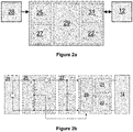
- the electrical assembly 10 further includes a controller, a power supply detection unit 25, a position detection unit 22, and a local power source 27, as shown in Figure 2a .
- the controller includes a processor 29 and a relay driver 31.
- the local power source 27 is in the form of an energy-storing capacitor which supplies power to the position detection unit 22 and the controller. In other embodiments, the capacitor may be replaced by a battery or by another independent power source.
- the position detection unit 22 is configured to detect an inductance of the inductive coil 14 or a characteristic that corresponds to an inductance of the inductive coil 14.
- the position detection unit 22 is further configured to determine the position of the armature 16 based on the detected inductance or detected characteristic, and to communicate the detected position of the armature 16 to the processor 29 via an electrical signal.
- the switching assembly 10 further still includes a control unit 24 which is configured to control the voltage across the inductive coil 14 so as to apply a voltage step to the inductive coil 14.
- control unit 24 is configured to control the magnitude of the voltage step so that the voltage across the inductive coil 14 is controlled at a value that maintains the position of the armature 16, i.e. it does not cause movement of the armature 16.
- the magnitude of the voltage step applied to the inductive coil 14 may be controlled so that the voltage across the inductive coil 14 is controlled at a value lower than the voltage required to move the armature 16 between the first and second positions.
- the magnitude of the voltage step applied to the inductive coil 14 may be controlled so that the voltage across the inductive coil 14 is controlled at a value equal to or higher than the voltage required to move the armature 16 but is applied to the inductive coil 14 for an amount of time that is not long enough to influence the position of the armature 16 at that value.
- a voltage step lower than the voltage required to move the armature 16 could be applied while the inductive coil 14 is de-energised (i.e. while there is no current flow through the inductive coil 14).
- Another option would be to apply a nominal voltage step but for a very short duration with respect to the mechanical inertia of the latching device 12 such that the mechanical inertia of the armature 16 will not allow the armature 16 to move.
- the nominal voltage could then be applied while the inductive coil 14 is either energised or de-energised.
- a voltage step could be applied while the inductive coil 14 is energised (i.e. while there is a current flow through the inductive coil 14). Such a voltage step could be applied in several ways such that the voltage across the inductive coil 14 is increased (e.g. doubled), thus increasing the force on the armature 16 being held in the current position. Alternatively, the voltage step could be applied for a short period of time. Any other type of voltage step pattern can be applied which does not move the armature 16 out of position.
- the position detection unit 22 is configured to detect the inductance of the inductive coil 14 or a characteristic that corresponds to the inductance of the inductive coil 14 in response to the voltage step being applied to the inductive coil 14 by the control unit 24.
- the position detection unit 22 is configured to detect a characteristic that corresponds to the inductance of the inductive coil 14.
- the position detection unit 22 is configured to monitor a rate of change of current of the inductive coil 14 when the voltage step is applied to the inductive coil 14.
- the position detection unit 22 may instead be configured to directly detect the inductance of the inductive coil 14.
- Such a relationship can be utilised when applying the voltage step v ( t ) to the inductive coil and monitoring the rate of change of current di dt of the inductive coil 14 to detect the inductance L of the inductive coil 14.
- the position detection unit 22 includes a sensing device which senses the current of the inductive coil 14.
- the sensing device in the embodiment shown is part of a voltage comparator unit 23, which not only senses the current of the inductive coil 14 via a voltage measurement, but also compares the voltage measurement to a voltage threshold.
- the voltage comparator unit 23 may instead be a current comparator which directly measures the current of the inductive coil 14 and compares it with a current threshold.
- the voltage comparator 23 may instead be an inductance comparator which directly measures the inductance of the inductive coil 14 and compares it with an inductance threshold.
- the position detection unit 22 also includes a timing unit (not shown) which detects a time interval for the current of the inductive coil 14 to reach a current threshold when the voltage step is applied.
- the current threshold may be a final steady state current value or may instead be a predetermined current threshold.
- the voltage comparator unit 23 forms part of a higher-level comparator (not shown) which is configured to compare the detected characteristic with a reference characteristic threshold.
- the detected characteristic is compared with a reference characteristic value. In other embodiments of the invention, the detected characteristic may be compared with a reference characteristic range.
- the detected characteristic may be a rate of change of current across the inductive coil 14 which is compared to a reference rate of change of current value.
- the detected characteristic may instead be a rate of change of voltage across the inductive coil 14 which is compared to a reference rate of change of voltage value.
- the detected characteristic may instead be a time interval for the current (or voltage) across the inductive coil 14 to reach the threshold current (or voltage) value which is then compared to a reference time interval value.
- the timing unit may set a fixed time for the current of the inductive coil 14 to be measured by the sensing device.
- the current, or rate of change of current, after the fixed time may then be compared to a reference current, or rate of change of current, value so as to determine the position of the armature 16.
- the switching assembly 10 includes a calibration unit (not shown) which performs a self-calibration of the switching assembly 10 by measuring the characteristic that corresponds to the inductance of the inductive coil 14 with the armature 16 in the first and second positions (or any other possible positions of the armature 16).
- the switching assembly 10 may include a self-calibration circuit (not shown) with software which will command the latching device 12 to move the armature 16 to one of the first and second positions and then measure the inductance (or a characteristic thereof) in each of the positions.
- a reference characteristic value will then be computed by the calibration unit. Once the reference characteristic value is computed by the calibration unit, that reference characteristic value will be used to decide the position of the armature 16 by comparing the detected characteristic with the reference characteristic value.
- the reference characteristic value is determined externally to the switching assembly 10 and is instead stored and/or hardcoded into the latching device 12.
- the latching device 12 in the embodiment shown is an electromechanical relay, in particular a latching relay 26 which is configured to selectively hold the armature 16 in position when the inductive coil 14 is de-energised.
- the latching relay 26 may also be known in the art as an "impulse”, "keep” or “stay” relay.
- the latching relay 26 may include two opposing inductive coils 14 with an over-centre spring or permanent magnet to hold the armature 16 in position after the inductive coil 14 is de-energised, wherein a pulse to one inductive coil 14 moves the armature 16 to the first position and a pulse to the opposite inductive coil 14 moves the armature 16 to the second position.
- the position detection unit 22 is preferably configured to detect the characteristic that corresponds to the inductance of the inductive coil 14 when the inductive coil 14 is de-energised.
- the latching relay 26 includes first and second independent inductive coils S, R.
- the first coil S is known as a “set coil” and the second coil is known as a “reset coil”.
- the input circuit 18 is connected to the first and second inductive coils S, R such that a current can be separately supplied to the first and second inductive coils S, R so as to separately energise the inductive coils S, R, and thus move the armature 16 to one of the first and second positions.
- an electrical power source 28 is connected into and out of the input circuit 18 via a supply switching element 30 in order to allow a power supply from the electrical power source 28 to the first and second inductive coils S, R.
- the input circuit 18 also includes a first coil switching element 32 and a second coil switching element 34. To energise the first inductive coil S, both the supply switching element 30 and the first coil switching element 32 must be closed while the second coil switching element 34 is open. To energise the second inductive coil R, both the supply switching element 30 and the second coil switching element 34 must be closed while the first coil switching element 32 is open.
- Switching of the supply switching element 30 and the first and second coil switching elements 32, 34 is controlled by the control unit 24.
- the input circuit 18 further includes a resistive element 36 which is connected in parallel with the first coil switching element 32.
- the resistive element 36 permits the detecting unit 22 to sense the current of the first inductive coil S since it permits the voltage across the resistive element 36 to be measured, which is proportional to the current of the first inductive coil S.
- the position detection unit 22 and the control unit 24 may form part of the same unit or may instead be separate units.
- the latching device 12 may include a fewer or higher number of inductive coils 14.
- the latching relay 12 may be replaced by a different type of latching switching device such as a circuit breaker.
- the latching device 12 may further include one or more magnetic cores (not shown) around which a respective inductive coil 14 is wrapped.
- the or each magnetic core may be a piece of ferromagnetic material such as iron.
- the control unit 24 closes both the supply switching element 30 and the first inductive coil switching element 32 for a predetermined amount of time to permit a current to flow through the first inductive coil S so as to energise the first inductive coil S enough to move the armature 16.
- the armature 16 is moved by the energised first inductive coil S from the first position by which the moveable contact 17 is in an open position relative to the output circuit 20 (i.e. the "reset position") to the second position by which the moveable contact 17 is in a closed position relative to the output circuit 20 (i.e. the "set position").
- the control unit 24 then opens the supply switching element 30 and the first inductive coil switching element 32, thus ceasing the current flow through the first inductive coil S which de-energises the first inductive coil S.
- the latching device 12 shown is a latching relay 26
- the armature 16 is held in the second position (i.e. the last position of the armature 16) while the first inductive coil S is de-energised.
- the control unit 24 closes both the supply switching element 30 and the second inductive coil switching element 34 for a predetermined amount of time to permit a current to flow through the second inductive coil R so as to energise the second inductive coil R enough to move the armature 16.
- the armature 16 is moved by the energised second inductive coil R from the second position to the first position.
- the control unit 24 then opens the supply switching element 30 and the second inductive coil switching element 34, thus ceasing the current flow through the second inductive coil R which de-energises the second inductive coil R.
- the latching device 12 shown is a latching relay 26
- the armature 16 is held in the first position (i.e. the last position of the armature 16) while the second inductive coil R is de-energised.
- a turn-off or loss of power supply from the electrical power source 28 to the first and second inductive coils S, R may take place, whereby such a turn-off or loss of power supply may be intentional or unexpected or may be scheduled or unscheduled.
- the power supply detection unit 25 is configured to detect a turn-off or loss of power supply from the electrical power source 28 to the first and second inductive coils S, R, and to communicate information about the turn-off or loss of power supply to the processor 29.
- FIG. 2b shows an exemplary implementation of the power supply detection unit 25 in which an anode side of a diode is connected to the electrical power source 28, a cathode side of the diode is connected to the processor 29, and a voltage divider is connected across the electrical power source 28 at the anode side of the diode, with a mid-point between a pair of resistors of the voltage divider being connected to the processor 29.
- the capacitor 27 is connected between the cathode side of the diode and the processor 29. Upon turn-off or loss of the power supply from the electrical power source 28, the anode side of the diode goes to 0 which can be sensed by the processor 29 through the voltage divider. Meanwhile the arrangement of the capacitor 27 permits the processor 29 to draw power from the capacitor 27 to enable its operation.
- the power supply detection unit 25 may implemented in a different manner.
- the power supply detection unit 25 may be implemented as a dedicated integrated power supply monitoring integrated circuit, which can be powered by the capacitor 27.
- the processor 29 is configured to receive the information about the turn-off or loss of power supply from the power supply detection unit 22, and to send a command to the relay driver 31 to drive either of the first and second inductive coils S, R in order to move the armature 16 from its last position (which is either of the first and second positions) to the other of the first and second positions.
- the driving of the first or second inductive coil S, R is carried out by drawing power from the capacitor 27 to energise the first or second inductive coil S, R. It is envisaged that the power for energising the first or second inductive coil S, R may be instead drawn from another independent power source, such as a battery.
- the controller is configured to selectively drive the inductive coils S, R to move the armature 16 to a selected one of the first and second positions in response to the detection of the turn-off or loss of power supply.
- the position detection unit 22 can be used to determine the position of the armature 16, which will then be communicated to the processor 29. This enables the processor to decide whether it is necessary to command the relay driver 31 to drive either of the first and second inductive coils S, R in order to move the armature 16. If the armature 16 is not in a desired position, then the processor 29 commands the relay driver 31 to drive either of the first and second inductive coils S, R in order to move the armature 16 to the other position. If the armature 16 is already in a desired position, then there is no need to drive either of the first and second inductive coils S, R to move the armature 16 to the other position.
- the control unit 24 is implemented to apply the voltage step to the first inductive coil S.
- the voltage step does not influence the present position of the armature 16. This might be achieved by the voltage step being kept lower than the voltage required to move the armature 16 between the first and second positions, or by the voltage step being applied for an amount of time that does not permit the armature 16 to move between the first and second positions.
- the voltage step is applied by the control unit 24 closing the supply switching element 30 so that current starts to flow through the first inductive coil S and the resistive element 36. As the current flow builds up the voltage V m across the resistive element 36 also increases.
- the timing unit activates.
- the comparator unit 23 which in this embodiment is a voltage comparator, compares the voltage V m across the resistive element 36 to a voltage threshold V th . When the voltage V m across the resistive element 36 reaches the voltage threshold V th , the comparator unit 23 will output a toggle, e.g. it will output a high digital signal V o .
- the timing unit deactivates once the comparator unit 23 outputs the digital signal, i.e. it stops timing. Thus a time interval for the voltage V m across the resistive element 36 to reach the voltage threshold V th is obtained.
- the amount of time it takes for the voltage V m across the resistive element 36 to reach the voltage threshold V th is dependent on the time it takes for the current to build up across the first inductive coil S, which in turn is dependent on the inductance of the first inductive coil S. In this way, a characteristic that corresponds to the inductance of the first inductive coil S is detected.
- the position detection unit 22 compares the time interval obtained by the timing unit (i.e. the detected characteristic) to a reference time interval value (i.e. the reference characteristic threshold - which in this case is a value) to determine the position of the armature 16.
- a reference time interval value i.e. the reference characteristic threshold - which in this case is a value
- the voltage threshold V th may be a final steady state voltage value.
- the voltage threshold V th may instead be another voltage which is pre-measured and indicative of the armature 16 being in a particular position.
- the position detection unit 22 may instead calculate the rate of change of current during the time interval and then compare the rate of change of current (i.e. the detected characteristic) to a rate of change of current reference value (i.e. the reference characteristic threshold) to determine the position of the armature 16.
- the position detection unit 22 may instead calculate the rate of change of voltage during the time interval and then compare the rate of change of voltage (i.e. the detected characteristic) to a rate of change of voltage reference value (i.e. the reference characteristic threshold) to determine the position of the armature 16.
- the position detection unit 22 may instead measure the current during the time interval and then compare the measured current (i.e. the detected characteristic) to a current reference value (i.e. the reference characteristic threshold) to determine the position of the armature 16.
- the position detection unit 22 may instead calculate the inductance (using the equation as set out previously in the application) or directly detect the inductance of the first inductive coil S and then compare the detected inductance to a reference inductance value (i.e. the reference inductance threshold) to determine the position of the armature 16.
- a reference inductance value i.e. the reference inductance threshold
- the timing unit may stop after a pre-determined time interval and the position detection unit 22 may measure the current, voltage, rate of change of current or rate of change of voltage at the end of the time interval (i.e. the detected characteristic). The measured current, voltage, rate of change of current or rate of change of voltage may then be compared to a reference current, reference voltage, reference rate of change of current, or reference rate of change of voltage value (i.e. the reference characteristic threshold) so as to determine the position of the armature 16.
- a reference current, reference voltage, reference rate of change of current, or reference rate of change of voltage value i.e. the reference characteristic threshold
- the steps outlined above are for use with a particular type of latching relay 26 as shown in the figures which includes two inductive coil windings.
- the same idea of detecting the inductance (or a characteristic thereof) of the inductive coil 14 in order to determine the position of the armature 16 can be applied to any other relay or relay like devices, such as actuators, circuit breakers etc. by implementing an identical or similar position detection unit 22 without affecting the normal operation of the latching device 12, and also to any other device that includes an inductive coil and an armature, with the armature arranged to be moveable between first and second positions when the inductive coil is energised.
- the configuration of the switching assembly 10 of Figures 1 and 3 therefore enables the selective movement of the armature 16 to the selected one of the first and second positions following the turn-off or loss of power supply, which enables the control of the position of the armature 16 to ensure that the switching relay 12 is in a certain state following the turn-off or loss of power supply so that the output circuit 20 is in a preferred standby configuration when the power supply from the electrical power source 28 to the inductive coils S, R is restored.
- This not only allows the switching relay 12 to be used in new ways, such as in applications requiring a controlled state of the switching relay 12 upon power-on, but also provides the switching relay 12 with multiple controlled states following the turn-off or loss of power supply.
- the invention enables the switching relay 12 to replace the conventional non-latching relay while avoiding the problem associated with the conventional latching relay having an uncontrolled state upon power-on, thus providing the benefits of reduced power consumption and lower operating temperature associated with latching relays which improves performance and reliability.
- the latching device 12 may experience an unexpected event, such as the application of excessive mechanical shock or vibration to the latching device 12, which could result in an accidental change in position of the armature 16.
- the position detection unit 22 is configured to detect the position of the armature 16 and communicate the detected position of the armature 16 to the processor 29.
- the processor 29 is programmed to obtain the target position of the armature 16 from, for example, an internal memory, an internal hard-coded data source, or an external data source.
- the target position of the armature 16 at a given point in time depends on the requirements of the operation of the latching device 12.
- the processor 29 then compares the detected position of the armature 16 and the target position of the armature 16, and decides whether it is necessary to command the relay driver 31 to drive either of the first and second inductive coils S, R in order to move the armature 16.
- the processor 29 commands the relay driver 31 to drive either of the first and second inductive coils S, R in order to move the armature 16 to the other position. If the detected position of the armature 16 is the same as the target position of the armature 16, then there is no need to drive either of the first and second inductive coils S, R to move the armature 16 to the other position.
- the switching assembly 10 of Figures 1 and 3 is therefore capable of initialising a corrective action to enable the selective movement of the armature 16 to a selected one of the first and second positions in response to an unexpected change in the position of the armature 16, which allows the latching device 12 to resume normal operation instead of being in a state which could negatively affect the performance of or cause damage to the latching device 12 and/or associated equipment.
- the switching assembly may be configured to enable the selective movement of the armature to the selected one of the first and second positions in response to one, instead of both, of: the turn-off or loss of power supply; and the mismatch between the detected position of the armature and the target position of the armature.
- the power supply detection unit may be omitted from the switching assembly.
- the invention is also applicable to other abnormal operating states of the latching device in addition to the aforementioned turn-off or loss of power supply and the mismatch between the detected position of the armature 16 and the target position of the armature, where the switching assembly is required to enable the selective movement of the armature to a selected one of the first and second positions following the occurrence of the abnormal operating state(s).
Landscapes
- Physics & Mathematics (AREA)
- Electromagnetism (AREA)
- Relay Circuits (AREA)
Abstract
There is provided an electrical assembly comprising:a latching device (12) including a latching member configured to be positionable in a first position and a second position, the latching device (12) further including an actuator configured to selectively move the latching member between the first and second positions;an operating state detection unit (22,25) configured to detect an abnormal operating state of the latching device (12); anda controller configured to selectively drive the actuator to move the latching member to a selected one of the first and second positions in response to the detection of the abnormal operating state.
Description
- This invention relates to an electrical assembly and to a method of operating an electrical assembly, particularly for use in switching relay applications.
- It is known to use a latching device with a latching member moveable between first and second positions, where the latching member may be held in either or both of the first and second positions. Such a device may be used to selectively open and close an electrical circuit.
- According to a first aspect of the invention, there is provided an electrical assembly comprising:
- a latching device including a latching member configured to be positionable in a first position and a second position, the latching device further including an actuator configured to selectively move the latching member between the first and second positions;
- an operating state detection unit configured to detect an abnormal operating state of the latching device; and
- a controller configured to selectively drive the actuator to move the latching member to a selected one of the first and second positions in response to the detection of the abnormal operating state.
- It will be understood that the invention is applicable to electrical assemblies with a latching member configured to be positionable in two or more different positions, i.e. the latching member is not limited to being positionable in only the first and second positions. For example, the latching member may be moveable by the actuator to the first position, the second position and at least one other position.
- The provision of the operating state detection unit and the controller in the electrical assembly of the invention enables the selective movement of the latching member to the selected one of the first and second positions following the occurrence of the abnormal operating state. This allows the position of the latching member to be controlled so that the latching device is in a desired state when the latching device is restored to a normal operating state. This is advantageous in applications where the latching device is required to be in a certain state in order to improve the performance of or prevent damage to the latching device and/or associated equipment.
- In embodiments of the invention, the actuator may be an electrically operated actuator which is configured to be electrically connectable to an electrical power source to allow a power supply from the electrical power source to the actuator. In such embodiments, the operating state detection unit may include a power supply detection unit, and the abnormal operating state may include a turn-off or loss of power supply from the electrical power source to the actuator.
- It will be understood that the turn-off or loss of power supply from the electrical power source to the actuator may be intentional or unexpected, and may be scheduled or unscheduled.
- The provision of the power supply detection unit and the controller in the electrical assembly of the invention enables the selective movement of the latching member to the selected one of the first and second positions following the turn-off or loss of power supply. This allows the position of the latching member to be controlled so that the latching device is in a desired state when the power supply from the electrical power source to the actuator is restored. This is advantageous in applications where the latching device is required to be in a certain state upon power-on in order to improve the performance of or prevent damage to the latching device and/or associated equipment.
- In contrast, as seen in electrical assemblies with conventional latching devices, the absence of the aforementioned power supply detection unit and controller means that the turn-off or loss of power supply would prevent the operation of the actuator to move the latching member to the selected position. As a result, the latching member can only be maintained in its last position, thus resulting in the latching device having an uncontrolled state upon power-on. This runs the risk of degrading the performance of or damaging the latching device and/or associated equipment.
- A conventional non-latching device is designed to have a fixed state in the event of a turn-off or loss of power supply, which avoids the problem associated with the conventional latching device having an uncontrolled state upon power-on. On the other hand the conventional non-latching device has the downside of requiring a constant supply of power in its energised position and therefore a higher operating temperature when compared to a latching device. The ability of the invention to provide a configurable position of the latching member following the turn-off or loss of power supply enables a latching device to replace the conventional non-latching device while avoiding the problem associated with the conventional latching device having an uncontrolled state upon power-on, thus providing the benefits of reduced power consumption and lower operating temperature associated with latching devices which improves performance and reliability. This may be advantageously applied to, for example, applications with power saving requirements or with critical power dissipation and/or operating temperature requirements, since the invention enables the latching device to operate with reduced power dissipation and thereby run at cooler temperatures in comparison to the conventional non-latching device.
- In addition the ability of the invention to control the position of the latching member following the turn-off or loss of power supply allows the latching device of the invention to be used in new ways, such as in applications requiring a controlled state of the latching device upon power-on.
- Furthermore, by way of the invention permitting the positioning of the latching member in either of the first and second positions following the turn-off or loss of power supply, the latching device of the invention is provided with multiple controlled states following the turn-off or loss of power supply, unlike the conventional non-latching device which is limited to a fixed state following the turn-off or loss of power supply.
- In further embodiments of the invention, the electrical assembly may include a position detection unit, wherein the position detection unit includes a sensing device configured to detect the position of the latching member, and the position detection unit may be configured to communicate the detected position of the latching member to the controller.
- This enables the controller to decide whether it is necessary to drive the actuator to move the latching member to the selected one of the first and second positions in response to the detection of the abnormal operating state. If the latching member is not in a desired position, then the controller drives the actuator to move the latching member to the selected position. If the latching member is already in a desired position, then there is no need for the actuator to move the latching member to the selected position. This is particularly advantageous for when the latching member has multiple stable positions but only one or some, but not all, of the multiple stable positions are desirable for the latching member when there is an abnormal operating state of the latching device.
- During its operation, the latching device may experience an unexpected event, such as an application of an external mechanical force to the latching member, which could result in an accidental change in position of the latching member.
- In embodiments of the invention employing the use of a position detection unit, the operating state detection unit may include the position detection unit. In such embodiments, the abnormal operating state may include a mismatch between the detected position of the latching member and a target position of the latching member.
- Configuration of the electrical assembly of the invention in this manner enables the detection of the change in position of the latching member, which in turn allows the controller to correct the position of the latching member to match the target position of the latching member. This allows the latching device to resume normal operation instead of being in a state which could negatively affect the performance of or cause damage to the latching device and/or associated equipment.
- The invention is applicable to electrical assemblies based on different configurations of latching devices for use in a wide range of applications. Non-limiting examples of such electrical assemblies are described as follows.
- In embodiments of the invention, the latching member may include an armature, and the actuator may include an inductive coil, the armature arranged to be moveable between the first and second positions when the inductive coil is energised.
- In such embodiments employing the use of the aforementioned position detection unit, the sensing device may be configured to detect an inductance of the inductive coil or a characteristic that corresponds to the inductance of the inductive coil, the position detection unit further configured to determine the position of the armature based on the detected inductance or the detected characteristic.
- The ability to confirm the mechanical position of an armature permits the invention to provide information on the state of the latching device. Having a position detection unit capable of detecting an inductance of the inductive coil or a characteristic that corresponds to the inductance of the inductive coil, and determining the position of the armature based on the detected inductance or the detected characteristic provides a reliable and cost-effective way of confirming the position of the armature.
- The inductance of the inductive coil is influenced by the position of the armature since the armature affects the magnetic circuit of the coil. As such, detecting the inductance of the inductive coil or a characteristic that corresponds to the inductance of the inductive coil permits the position of the armature to be determined.
- Detecting an inductance of the inductive coil means that the inductance of the inductive coil is directly obtained. Detecting a characteristic that corresponds to the inductance of the inductive coil means that a value that corresponds to the inductance of the inductive coil, e.g. current, time, rate of change of current, rate of change of voltage or voltage, is obtained.
- Optionally the electrical assembly may include a local power source configured to selectively supply power to one or more components of the electrical assembly. The local power source may be configured to supply power for operating the operating state detection unit, the controller and/or any other component of the electrical assembly mentioned in this specification. This provides a reliable means for enabling the driving of the actuator to move the latching member to the selected one of the first and second positions in response to the detection of the abnormal operating state.
- In further embodiments of the invention, the latching device may be a latching switching device, such as a relay, a circuit breaker or any other type of switching device. In such embodiments, the latching member may include at least one contact element.
- The invention is particularly useful for applications in which the latching relay is required to be in a certain state following the occurrence of the abnormal operating state. For example, there may be a need to ensure that the latching relay is in a certain state following the occurrence of the abnormal operating state so that an associated electrical circuit is in a preferred standby configuration while waiting for the restoration of the normal operating state of the latching device. This not only optimises the performance of the electrical circuit while on standby, but also prevents the undesirable scenario of the electrical circuit being in the wrong configuration, which could potentially damage the electrical circuit and/or associated equipment.
- Alternatively the latching device may be an electromechanical actuator, a trip coil solenoid or any other type of non-switching device.
- According to a second aspect of the invention, there is provided a method of operating an electrical assembly, the electrical assembly comprising a latching device including a latching member configured to be positionable in a first position and a second position, the latching device further including an actuator configured to selectively move the latching member between the first and second positions, the method comprising the steps of:
- detecting an abnormal operating state of the latching device; and
- selectively driving the actuator to move the latching member to a selected one of the first and second positions in response to the detection of the abnormal operating state.
- The advantages of the electrical assembly of the first aspect of the invention and its embodiments apply mutatis mutandis to the method of the second aspect of the invention and its embodiments.
- In embodiments of the second aspect of the invention, the actuator may be an electrically operated actuator which is configured to be electrically connectable to an electrical power source to allow a power supply from the electrical power source to the actuator. In such embodiments, the abnormal operating state may include a turn-off or loss of power supply from the electrical power source to the actuator.
- In further embodiments of the second aspect of the invention, the method of the invention may include the step of detecting the position of the latching member. In such embodiments, the abnormal operating state may include a mismatch between the detected position of the latching member and a target position of the latching member.
- In the method of the invention, the latching member may include an armature, and the actuator may include an inductive coil, the armature arranged to be moveable between the first and second positions when the inductive coil is energised.
- The method of the invention may include the steps of detecting an inductance of the inductive coil or a characteristic that corresponds to the inductance of the inductive coil, and determining the position of the armature based on the detected inductance or the detected characteristic.
- The method of the invention may include the step of selectively supplying power from a local power source to one or more components of the electrical assembly.
- In the method of the invention, the latching device may be a switching device, an electromechanical actuator, a trip coil solenoid or any other type of non-switching device.
- A preferred embodiment of the invention will now be described, by way of a non-limiting example, with reference to the accompanying drawings in which:
-
Figure 1 shows a schematic view of an electrical assembly according to an embodiment of the invention with an armature in a first position; and -
Figures 2a and 2b show schematic views of a controller, a power supply detection unit, a position detection unit and a local power source of the electrical assembly ofFigure 1 ; and -
Figure 3 shows a schematic view of the electrical assembly ofFigure 1 with the armature in a second position. - An electrical assembly according to an embodiment of the invention is shown in
Figure 1 and is designated generally by thereference numeral 10. - The
electrical assembly 10 includes a latching device in the form of a latchingrelay 12. As such, theelectrical assembly 10 is a switchingassembly 10 in the embodiment shown. In other embodiments of the invention, the latching device may instead be a non-switching device, such as an electromechanical actuator or a trip coil solenoid. - The latching
relay 12 includes aninductive coil 14 and anarmature 16. Thearmature 16 is arranged to be moveable between first and second positions when theinductive coil 14 is energised. - The
armature 16 includes amoveable contact 17 which is moveable with thearmature 16 between the first and second positions. In the embodiment shown, themoveable contact 17 is mechanically linked to thearmature 16 e.g. via a pivot. In other embodiments of the invention, themoveable contact 17 may not be mechanically linked to thearmature 16 and may instead be mechanically linked to another part of the switchingassembly 10 which permits movement of themoveable contact 17 when thearmature 16 abuts themoveable contact 17. - In still other embodiments of the invention, the
armature 16 may be integrally formed with themoveable contact 17. - The
inductive coil 14 forms part of aninput circuit 18, and the armature 16 (in particular the moveable contact 17) forms part of anoutput circuit 20. In the embodiment shown, theinput circuit 18 operates at a lower current than theoutput circuit 20. In other embodiments of the invention theoutput circuit 20 may instead operate at a lower or the same current as theinput circuit 18. In further other embodiments of the invention theinductive coil 14 forms part of an output circuit while the armature 16 (in particular, the moveable contact 17) forms part of an input circuit. -
Figure 1 shows thearmature 16 in the first position wherein thearmature 16 has moved themoveable contact 17 to an open position relative to a fixedcontact 21 of theoutput circuit 20 such that current is prevented from flowing through theoutput circuit 20. -
Figure 3 shows thearmature 16 in the second position wherein thearmature 16 has moved themoveable contact 17 to a closed position relative to the fixedcontact 21 of theoutput circuit 20 such that current is permitted to flow through theoutput circuit 20. - The latching
relay 12 may be a "normally open" device wherein thearmature 16 is in the first position by default. In other embodiments however the latchingrelay 12 may instead be a "normally closed" device wherein thearmature 16 is in the second position by default. - The
electrical assembly 10 further includes a controller, a powersupply detection unit 25, aposition detection unit 22, and alocal power source 27, as shown inFigure 2a . The controller includes aprocessor 29 and arelay driver 31. Thelocal power source 27 is in the form of an energy-storing capacitor which supplies power to theposition detection unit 22 and the controller. In other embodiments, the capacitor may be replaced by a battery or by another independent power source. - The
position detection unit 22 is configured to detect an inductance of theinductive coil 14 or a characteristic that corresponds to an inductance of theinductive coil 14. Theposition detection unit 22 is further configured to determine the position of thearmature 16 based on the detected inductance or detected characteristic, and to communicate the detected position of thearmature 16 to theprocessor 29 via an electrical signal. - The switching
assembly 10 further still includes acontrol unit 24 which is configured to control the voltage across theinductive coil 14 so as to apply a voltage step to theinductive coil 14. - In particular, the
control unit 24 is configured to control the magnitude of the voltage step so that the voltage across theinductive coil 14 is controlled at a value that maintains the position of thearmature 16, i.e. it does not cause movement of thearmature 16. - The magnitude of the voltage step applied to the
inductive coil 14 may be controlled so that the voltage across theinductive coil 14 is controlled at a value lower than the voltage required to move thearmature 16 between the first and second positions. Alternatively, the magnitude of the voltage step applied to theinductive coil 14 may be controlled so that the voltage across theinductive coil 14 is controlled at a value equal to or higher than the voltage required to move thearmature 16 but is applied to theinductive coil 14 for an amount of time that is not long enough to influence the position of thearmature 16 at that value. - A voltage step lower than the voltage required to move the
armature 16 could be applied while theinductive coil 14 is de-energised (i.e. while there is no current flow through the inductive coil 14). Another option would be to apply a nominal voltage step but for a very short duration with respect to the mechanical inertia of the latchingdevice 12 such that the mechanical inertia of thearmature 16 will not allow thearmature 16 to move. The nominal voltage could then be applied while theinductive coil 14 is either energised or de-energised. - A voltage step could be applied while the
inductive coil 14 is energised (i.e. while there is a current flow through the inductive coil 14). Such a voltage step could be applied in several ways such that the voltage across theinductive coil 14 is increased (e.g. doubled), thus increasing the force on thearmature 16 being held in the current position. Alternatively, the voltage step could be applied for a short period of time. Any other type of voltage step pattern can be applied which does not move thearmature 16 out of position. - The
position detection unit 22 is configured to detect the inductance of theinductive coil 14 or a characteristic that corresponds to the inductance of theinductive coil 14 in response to the voltage step being applied to theinductive coil 14 by thecontrol unit 24. - In the embodiment shown, the
position detection unit 22 is configured to detect a characteristic that corresponds to the inductance of theinductive coil 14. In particular, theposition detection unit 22 is configured to monitor a rate of change of current of theinductive coil 14 when the voltage step is applied to theinductive coil 14. Theposition detection unit 22 may instead be configured to directly detect the inductance of theinductive coil 14. - The relationship between the inductance of an electrical circuit, the current through the circuit and the voltage across the circuit is shown below:

- Such a relationship can be utilised when applying the voltage step v(t) to the inductive coil and monitoring the rate of change of current

inductive coil 14 to detect the inductance L of theinductive coil 14. - The
position detection unit 22 includes a sensing device which senses the current of theinductive coil 14. The sensing device in the embodiment shown is part of avoltage comparator unit 23, which not only senses the current of theinductive coil 14 via a voltage measurement, but also compares the voltage measurement to a voltage threshold. Thevoltage comparator unit 23 may instead be a current comparator which directly measures the current of theinductive coil 14 and compares it with a current threshold. Thevoltage comparator 23 may instead be an inductance comparator which directly measures the inductance of theinductive coil 14 and compares it with an inductance threshold. - The
position detection unit 22 also includes a timing unit (not shown) which detects a time interval for the current of theinductive coil 14 to reach a current threshold when the voltage step is applied. The current threshold may be a final steady state current value or may instead be a predetermined current threshold. - The
voltage comparator unit 23 forms part of a higher-level comparator (not shown) which is configured to compare the detected characteristic with a reference characteristic threshold. In the embodiment shown, the detected characteristic is compared with a reference characteristic value. In other embodiments of the invention, the detected characteristic may be compared with a reference characteristic range. - The detected characteristic may be a rate of change of current across the
inductive coil 14 which is compared to a reference rate of change of current value. The detected characteristic may instead be a rate of change of voltage across theinductive coil 14 which is compared to a reference rate of change of voltage value. - The detected characteristic may instead be a time interval for the current (or voltage) across the
inductive coil 14 to reach the threshold current (or voltage) value which is then compared to a reference time interval value. - Alternatively, the timing unit may set a fixed time for the current of the
inductive coil 14 to be measured by the sensing device. The current, or rate of change of current, after the fixed time may then be compared to a reference current, or rate of change of current, value so as to determine the position of thearmature 16. - To obtain the reference characteristic value to which the detected characteristic is compared, the switching
assembly 10 includes a calibration unit (not shown) which performs a self-calibration of the switchingassembly 10 by measuring the characteristic that corresponds to the inductance of theinductive coil 14 with thearmature 16 in the first and second positions (or any other possible positions of the armature 16). The switchingassembly 10 may include a self-calibration circuit (not shown) with software which will command the latchingdevice 12 to move thearmature 16 to one of the first and second positions and then measure the inductance (or a characteristic thereof) in each of the positions. A reference characteristic value will then be computed by the calibration unit. Once the reference characteristic value is computed by the calibration unit, that reference characteristic value will be used to decide the position of thearmature 16 by comparing the detected characteristic with the reference characteristic value. - In an alternative embodiment of the invention, the reference characteristic value is determined externally to the switching
assembly 10 and is instead stored and/or hardcoded into the latchingdevice 12. - The latching
device 12 in the embodiment shown is an electromechanical relay, in particular a latching relay 26 which is configured to selectively hold thearmature 16 in position when theinductive coil 14 is de-energised. The latching relay 26 may also be known in the art as an "impulse", "keep" or "stay" relay. - How a latching relay 26 holds an
armature 16 in position is known in the art. For example, the latching relay 26 may include two opposinginductive coils 14 with an over-centre spring or permanent magnet to hold thearmature 16 in position after theinductive coil 14 is de-energised, wherein a pulse to oneinductive coil 14 moves thearmature 16 to the first position and a pulse to the oppositeinductive coil 14 moves thearmature 16 to the second position. - The
position detection unit 22 is preferably configured to detect the characteristic that corresponds to the inductance of theinductive coil 14 when theinductive coil 14 is de-energised. - Returning to the embodiment shown in the figures, the latching relay 26 includes first and second independent inductive coils S, R. The first coil S is known as a "set coil" and the second coil is known as a "reset coil".
- The
input circuit 18 is connected to the first and second inductive coils S, R such that a current can be separately supplied to the first and second inductive coils S, R so as to separately energise the inductive coils S, R, and thus move thearmature 16 to one of the first and second positions. - In particular, an
electrical power source 28 is connected into and out of theinput circuit 18 via asupply switching element 30 in order to allow a power supply from theelectrical power source 28 to the first and second inductive coils S, R. Theinput circuit 18 also includes a firstcoil switching element 32 and a secondcoil switching element 34. To energise the first inductive coil S, both thesupply switching element 30 and the firstcoil switching element 32 must be closed while the secondcoil switching element 34 is open. To energise the second inductive coil R, both thesupply switching element 30 and the secondcoil switching element 34 must be closed while the firstcoil switching element 32 is open. - Switching of the
supply switching element 30 and the first and secondcoil switching elements control unit 24. - The
input circuit 18 further includes aresistive element 36 which is connected in parallel with the firstcoil switching element 32. Theresistive element 36 permits the detectingunit 22 to sense the current of the first inductive coil S since it permits the voltage across theresistive element 36 to be measured, which is proportional to the current of the first inductive coil S. - The
position detection unit 22 and thecontrol unit 24 may form part of the same unit or may instead be separate units. - In other embodiments of the invention, the latching
device 12 may include a fewer or higher number ofinductive coils 14. In further embodiments of the invention, the latchingrelay 12 may be replaced by a different type of latching switching device such as a circuit breaker. - The latching
device 12 may further include one or more magnetic cores (not shown) around which a respectiveinductive coil 14 is wrapped. The or each magnetic core may be a piece of ferromagnetic material such as iron. - To move the
armature 16 from the first position (Figure 1 ) to the second position (Figure 3 ), thecontrol unit 24 closes both thesupply switching element 30 and the first inductivecoil switching element 32 for a predetermined amount of time to permit a current to flow through the first inductive coil S so as to energise the first inductive coil S enough to move thearmature 16. Thearmature 16 is moved by the energised first inductive coil S from the first position by which themoveable contact 17 is in an open position relative to the output circuit 20 (i.e. the "reset position") to the second position by which themoveable contact 17 is in a closed position relative to the output circuit 20 (i.e. the "set position"). - The
control unit 24 then opens thesupply switching element 30 and the first inductivecoil switching element 32, thus ceasing the current flow through the first inductive coil S which de-energises the first inductive coil S. - Since the latching
device 12 shown is a latching relay 26, thearmature 16 is held in the second position (i.e. the last position of the armature 16) while the first inductive coil S is de-energised. - To move the
armature 16 from the second position (Figure 3 ) back to the first position (Figure 1 ), thecontrol unit 24 closes both thesupply switching element 30 and the second inductivecoil switching element 34 for a predetermined amount of time to permit a current to flow through the second inductive coil R so as to energise the second inductive coil R enough to move thearmature 16. Thearmature 16 is moved by the energised second inductive coil R from the second position to the first position. - The
control unit 24 then opens thesupply switching element 30 and the second inductivecoil switching element 34, thus ceasing the current flow through the second inductive coil R which de-energises the second inductive coil R. - Again, since the latching
device 12 shown is a latching relay 26, thearmature 16 is held in the first position (i.e. the last position of the armature 16) while the second inductive coil R is de-energised. - During the operation of the latching
device 12, a turn-off or loss of power supply from theelectrical power source 28 to the first and second inductive coils S, R may take place, whereby such a turn-off or loss of power supply may be intentional or unexpected or may be scheduled or unscheduled. - The power
supply detection unit 25 is configured to detect a turn-off or loss of power supply from theelectrical power source 28 to the first and second inductive coils S, R, and to communicate information about the turn-off or loss of power supply to theprocessor 29. -
Figure 2b shows an exemplary implementation of the powersupply detection unit 25 in which an anode side of a diode is connected to theelectrical power source 28, a cathode side of the diode is connected to theprocessor 29, and a voltage divider is connected across theelectrical power source 28 at the anode side of the diode, with a mid-point between a pair of resistors of the voltage divider being connected to theprocessor 29. In addition thecapacitor 27 is connected between the cathode side of the diode and theprocessor 29. Upon turn-off or loss of the power supply from theelectrical power source 28, the anode side of the diode goes to 0 which can be sensed by theprocessor 29 through the voltage divider. Meanwhile the arrangement of thecapacitor 27 permits theprocessor 29 to draw power from thecapacitor 27 to enable its operation. - It is envisaged that, in other embodiments, the power
supply detection unit 25 may implemented in a different manner. For example, the powersupply detection unit 25 may be implemented as a dedicated integrated power supply monitoring integrated circuit, which can be powered by thecapacitor 27. - The
processor 29 is configured to receive the information about the turn-off or loss of power supply from the powersupply detection unit 22, and to send a command to therelay driver 31 to drive either of the first and second inductive coils S, R in order to move thearmature 16 from its last position (which is either of the first and second positions) to the other of the first and second positions. The driving of the first or second inductive coil S, R is carried out by drawing power from thecapacitor 27 to energise the first or second inductive coil S, R. It is envisaged that the power for energising the first or second inductive coil S, R may be instead drawn from another independent power source, such as a battery. In this manner the controller is configured to selectively drive the inductive coils S, R to move thearmature 16 to a selected one of the first and second positions in response to the detection of the turn-off or loss of power supply. - Optionally the
position detection unit 22 can be used to determine the position of thearmature 16, which will then be communicated to theprocessor 29. This enables the processor to decide whether it is necessary to command therelay driver 31 to drive either of the first and second inductive coils S, R in order to move thearmature 16. If thearmature 16 is not in a desired position, then theprocessor 29 commands therelay driver 31 to drive either of the first and second inductive coils S, R in order to move thearmature 16 to the other position. If thearmature 16 is already in a desired position, then there is no need to drive either of the first and second inductive coils S, R to move thearmature 16 to the other position. - In order to detect the position of the
armature 16, thecontrol unit 24 is implemented to apply the voltage step to the first inductive coil S. The voltage step does not influence the present position of thearmature 16. This might be achieved by the voltage step being kept lower than the voltage required to move thearmature 16 between the first and second positions, or by the voltage step being applied for an amount of time that does not permit thearmature 16 to move between the first and second positions. - In the embodiment shown, the voltage step is applied by the
control unit 24 closing thesupply switching element 30 so that current starts to flow through the first inductive coil S and theresistive element 36. As the current flow builds up the voltage Vm across theresistive element 36 also increases. - When the
supply switching element 30 is closed, the timing unit activates. - The
comparator unit 23, which in this embodiment is a voltage comparator, compares the voltage Vm across theresistive element 36 to a voltage threshold Vth. When the voltage Vm across theresistive element 36 reaches the voltage threshold Vth, thecomparator unit 23 will output a toggle, e.g. it will output a high digital signal Vo. - The timing unit deactivates once the
comparator unit 23 outputs the digital signal, i.e. it stops timing. Thus a time interval for the voltage Vm across theresistive element 36 to reach the voltage threshold Vth is obtained. - The amount of time it takes for the voltage Vm across the
resistive element 36 to reach the voltage threshold Vth is dependent on the time it takes for the current to build up across the first inductive coil S, which in turn is dependent on the inductance of the first inductive coil S. In this way, a characteristic that corresponds to the inductance of the first inductive coil S is detected. - The
position detection unit 22 then compares the time interval obtained by the timing unit (i.e. the detected characteristic) to a reference time interval value (i.e. the reference characteristic threshold - which in this case is a value) to determine the position of thearmature 16. - The voltage threshold Vth may be a final steady state voltage value. The voltage threshold Vth may instead be another voltage which is pre-measured and indicative of the
armature 16 being in a particular position. - In other embodiments of the invention, the
position detection unit 22 may instead calculate the rate of change of current during the time interval and then compare the rate of change of current (i.e. the detected characteristic) to a rate of change of current reference value (i.e. the reference characteristic threshold) to determine the position of thearmature 16. - In further embodiments of the invention, the
position detection unit 22 may instead calculate the rate of change of voltage during the time interval and then compare the rate of change of voltage (i.e. the detected characteristic) to a rate of change of voltage reference value (i.e. the reference characteristic threshold) to determine the position of thearmature 16. - In further still embodiments of the invention, the
position detection unit 22 may instead measure the current during the time interval and then compare the measured current (i.e. the detected characteristic) to a current reference value (i.e. the reference characteristic threshold) to determine the position of thearmature 16. - In further still embodiments of the invention, the
position detection unit 22 may instead calculate the inductance (using the equation as set out previously in the application) or directly detect the inductance of the first inductive coil S and then compare the detected inductance to a reference inductance value (i.e. the reference inductance threshold) to determine the position of thearmature 16. - In further still embodiments of the invention, the timing unit may stop after a pre-determined time interval and the
position detection unit 22 may measure the current, voltage, rate of change of current or rate of change of voltage at the end of the time interval (i.e. the detected characteristic). The measured current, voltage, rate of change of current or rate of change of voltage may then be compared to a reference current, reference voltage, reference rate of change of current, or reference rate of change of voltage value (i.e. the reference characteristic threshold) so as to determine the position of thearmature 16. - The steps outlined above are for use with a particular type of latching relay 26 as shown in the figures which includes two inductive coil windings. However, the same idea of detecting the inductance (or a characteristic thereof) of the
inductive coil 14 in order to determine the position of thearmature 16 can be applied to any other relay or relay like devices, such as actuators, circuit breakers etc. by implementing an identical or similarposition detection unit 22 without affecting the normal operation of the latchingdevice 12, and also to any other device that includes an inductive coil and an armature, with the armature arranged to be moveable between first and second positions when the inductive coil is energised. - The configuration of the switching
assembly 10 ofFigures 1 and3 therefore enables the selective movement of thearmature 16 to the selected one of the first and second positions following the turn-off or loss of power supply, which enables the control of the position of thearmature 16 to ensure that the switchingrelay 12 is in a certain state following the turn-off or loss of power supply so that theoutput circuit 20 is in a preferred standby configuration when the power supply from theelectrical power source 28 to the inductive coils S, R is restored. This not only allows the switchingrelay 12 to be used in new ways, such as in applications requiring a controlled state of the switchingrelay 12 upon power-on, but also provides the switchingrelay 12 with multiple controlled states following the turn-off or loss of power supply. In addition the invention enables the switchingrelay 12 to replace the conventional non-latching relay while avoiding the problem associated with the conventional latching relay having an uncontrolled state upon power-on, thus providing the benefits of reduced power consumption and lower operating temperature associated with latching relays which improves performance and reliability. - In addition, during its operation, the latching
device 12 may experience an unexpected event, such as the application of excessive mechanical shock or vibration to the latchingdevice 12, which could result in an accidental change in position of thearmature 16. - As detailed above, the
position detection unit 22 is configured to detect the position of thearmature 16 and communicate the detected position of thearmature 16 to theprocessor 29. - The
processor 29 is programmed to obtain the target position of thearmature 16 from, for example, an internal memory, an internal hard-coded data source, or an external data source. The target position of thearmature 16 at a given point in time depends on the requirements of the operation of the latchingdevice 12. Theprocessor 29 then compares the detected position of thearmature 16 and the target position of thearmature 16, and decides whether it is necessary to command therelay driver 31 to drive either of the first and second inductive coils S, R in order to move thearmature 16. If there is a mismatch between the detected position of thearmature 16 and the target position of thearmature 16, then theprocessor 29 commands therelay driver 31 to drive either of the first and second inductive coils S, R in order to move thearmature 16 to the other position. If the detected position of thearmature 16 is the same as the target position of thearmature 16, then there is no need to drive either of the first and second inductive coils S, R to move thearmature 16 to the other position. - The switching
assembly 10 ofFigures 1 and3 is therefore capable of initialising a corrective action to enable the selective movement of thearmature 16 to a selected one of the first and second positions in response to an unexpected change in the position of thearmature 16, which allows the latchingdevice 12 to resume normal operation instead of being in a state which could negatively affect the performance of or cause damage to the latchingdevice 12 and/or associated equipment. - It is envisaged that, in other embodiments of the invention, the switching assembly may be configured to enable the selective movement of the armature to the selected one of the first and second positions in response to one, instead of both, of: the turn-off or loss of power supply; and the mismatch between the detected position of the armature and the target position of the armature. For the latter in which the switching assembly is configured to be responsive to the mismatch between the detected position of the armature and the target position of the armature, the power supply detection unit may be omitted from the switching assembly.
- It will be appreciated that the invention is also applicable to other abnormal operating states of the latching device in addition to the aforementioned turn-off or loss of power supply and the mismatch between the detected position of the
armature 16 and the target position of the armature, where the switching assembly is required to enable the selective movement of the armature to a selected one of the first and second positions following the occurrence of the abnormal operating state(s).
Claims (15)
- An electrical assembly (10) comprising:a latching device (12) including a latching member (16) configured to be positionable in a first position and a second position, the latching device (12) further including an actuator (14) configured to selectively move the latching member (16) between the first and second positions;an operating state detection unit (22,25) configured to detect an abnormal operating state of the latching device (12); anda controller configured to selectively drive the actuator (14) to move the latching member (16) to a selected one of the first and second positions in response to the detection of the abnormal operating state.
- An electrical assembly (10) according to Claim 1 wherein the actuator (14) is an electrically operated actuator (14) which is configured to be electrically connectable to an electrical power source (28) to allow a power supply from the electrical power source (28) to the actuator (14), the operating state detection unit includes a power supply detection unit (25), and the abnormal operating state includes a turn-off or loss of power supply from the electrical power source (28) to the actuator (14).
- An electrical assembly (10) according to Claim 1 or Claim 2 including a position detection unit (22), wherein the position detection unit (22) includes a sensing device configured to detect the position of the latching member (16), and the position detection unit (22) is configured to communicate the detected position of the latching member (16) to the controller.
- An electrical assembly (10) according to Claim 3 wherein the operating state detection unit includes the position detection unit (22), and the abnormal operating state includes a mismatch between the detected position of the latching member (16) and a target position of the latching member (16).
- An electrical assembly (10) according to any one of the preceding claims wherein the latching member (16) includes an armature (16), and the actuator (14) includes an inductive coil (14), the armature (16) arranged to be moveable between the first and second positions when the inductive coil (14) is energised.
- An electrical assembly (10) according to Claim 5 when dependent from either Claim 3 or Claim 4 wherein the sensing device is configured to detect an inductance of the inductive coil (14) or a characteristic that corresponds to the inductance of the inductive coil (14), the position detection unit (22) further configured to determine the position of the armature (16) based on the detected inductance or the detected characteristic.
- An electrical assembly (10) according to any one of the preceding claims including a local power source (27) configured to selectively supply power to one or more components of the electrical assembly (10).
- An electrical assembly (10) according to any one of the preceding claims wherein the latching device (12) is a switching device, an electromechanical actuator or a trip coil solenoid.
- A method of operating an electrical assembly (10), the electrical assembly (10) comprising a latching device (12) including a latching member (16) configured to be positionable in a first position and a second position, the latching device (12) further including an actuator (14) configured to selectively move the latching member (16) between the first and second positions, the method comprising the steps of:detecting an abnormal operating state of the latching device (12); andselectively driving the actuator (14) to move the latching member (16) to a selected one of the first and second positions in response to the detection of the abnormal operating state.
- A method according to Claim 9 wherein the actuator (14) is an electrically operated actuator (14) which is configured to be electrically connectable to an electrical power source (28) to allow a power supply from the electrical power source (28) to the actuator (14), and the abnormal operating state includes a turn-off or loss of power supply from the electrical power source (28) to the actuator (14).
- A method according to Claim 9 or Claim 10 including the step of detecting the position of the latching member (16).
- A method according to Claim 11 wherein the abnormal operating state includes a mismatch between the detected position of the latching member (16) and a target position of the latching member (16).
- A method according to any one of Claims 9 to 12 wherein the latching member (16) includes an armature (16), and the actuator (14) includes an inductive coil (14), the armature (16) arranged to be moveable between the first and second positions when the inductive coil (14) is energised.
- A method according to Claim 13 when dependent from either Claim 11 or Claim 12, the method including the steps of detecting an inductance of the inductive coil (14) or a characteristic that corresponds to the inductance of the inductive coil (14), and determining the position of the armature (16) based on the detected inductance or the detected characteristic.
- A method according to any one of Claims 9 to 14 including the step of selectively supplying power from a local power source (27) to one or more components of the electrical assembly (10).
Priority Applications (3)
| Application Number | Priority Date | Filing Date | Title |
|---|---|---|---|
| EP18155802.4A EP3525224A1 (en) | 2018-02-08 | 2018-02-08 | Electrical assembly |
| CA3032855A CA3032855A1 (en) | 2018-02-08 | 2019-02-06 | An electrical assembly |
| US16/271,045 US11499341B2 (en) | 2018-02-08 | 2019-02-08 | Electrical assembly |
Applications Claiming Priority (1)
| Application Number | Priority Date | Filing Date | Title |
|---|---|---|---|
| EP18155802.4A EP3525224A1 (en) | 2018-02-08 | 2018-02-08 | Electrical assembly |
Publications (1)
| Publication Number | Publication Date |
|---|---|
| EP3525224A1 true EP3525224A1 (en) | 2019-08-14 |
Family
ID=61188698
Family Applications (1)
| Application Number | Title | Priority Date | Filing Date |
|---|---|---|---|
| EP18155802.4A Withdrawn EP3525224A1 (en) | 2018-02-08 | 2018-02-08 | Electrical assembly |
Country Status (3)
| Country | Link |
|---|---|
| US (1) | US11499341B2 (en) |
| EP (1) | EP3525224A1 (en) |
| CA (1) | CA3032855A1 (en) |
Families Citing this family (1)
| Publication number | Priority date | Publication date | Assignee | Title |
|---|---|---|---|---|
| JP7520077B2 (en) * | 2022-07-25 | 2024-07-22 | 矢崎総業株式会社 | Relay Control Device |
Citations (1)
| Publication number | Priority date | Publication date | Assignee | Title |
|---|---|---|---|---|
| EP3312549A1 (en) * | 2016-10-21 | 2018-04-25 | General Electric Technology GmbH | An electrical assembly |
Family Cites Families (14)
| Publication number | Priority date | Publication date | Assignee | Title |
|---|---|---|---|---|
| US4648253A (en) * | 1985-05-13 | 1987-03-10 | American Institutional Maintenance Corporation | Cell lock |
| US5911460A (en) * | 1997-02-25 | 1999-06-15 | Georgia Tech Research Corp. | Jamb pocket latch bolt assembly release apparatus |
| DE102007035218A1 (en) * | 2007-07-25 | 2009-01-29 | Keba Ag | Electrically automated unlocking lock, especially for locker-like storage systems |
| DE202009005020U1 (en) * | 2009-07-14 | 2010-12-16 | Dewert Antriebs- Und Systemtechnik Gmbh | First-fail-safe electromotive furniture drive |
| US9617757B2 (en) * | 2010-02-25 | 2017-04-11 | Sargent Manufacturing Company | Locking device with configurable electrical connector key and internal circuit board for electronic door locks |
| US8325039B2 (en) * | 2010-02-25 | 2012-12-04 | Sargent Manufacturing Company | Locking device with embedded circuit board |
| US8686869B2 (en) * | 2010-12-29 | 2014-04-01 | Secureall Corporation | Alignment-related operation and position sensing of electronic and other locks and other objects |
| CA3000158C (en) * | 2012-07-13 | 2021-05-18 | Schlage Lock Company Llc | Electronic door lock assembly preload compensation system |
| US9316022B2 (en) * | 2012-12-18 | 2016-04-19 | Stanley Security Solutions, Inc. | Lock assembly having lock position sensor |
| US9447609B2 (en) * | 2013-03-15 | 2016-09-20 | August Home, Inc. | Mobile device that detects tappings/vibrations which are used to lock or unlock a door |
| US9850684B2 (en) * | 2014-07-17 | 2017-12-26 | Schlage Lock Company Llc | Sensor assemblies for locks |
| US9574375B2 (en) * | 2014-11-07 | 2017-02-21 | Kevin Henderson | Electronic lock |
| US11761242B2 (en) * | 2015-04-14 | 2023-09-19 | Hanchett Entry Systems, Inc. | Electric strike including a biasing mechanism for a keeper support bracket |
| US10704293B2 (en) * | 2015-12-01 | 2020-07-07 | Spectrum Brands, Inc. | Electronic lock with misalignment scoring system |
-
2018
- 2018-02-08 EP EP18155802.4A patent/EP3525224A1/en not_active Withdrawn
-
2019
- 2019-02-06 CA CA3032855A patent/CA3032855A1/en active Pending
- 2019-02-08 US US16/271,045 patent/US11499341B2/en active Active
Patent Citations (1)
| Publication number | Priority date | Publication date | Assignee | Title |
|---|---|---|---|---|
| EP3312549A1 (en) * | 2016-10-21 | 2018-04-25 | General Electric Technology GmbH | An electrical assembly |
Also Published As
| Publication number | Publication date |
|---|---|
| US20190242156A1 (en) | 2019-08-08 |
| CA3032855A1 (en) | 2019-08-08 |
| US11499341B2 (en) | 2022-11-15 |
Similar Documents
| Publication | Publication Date | Title |
|---|---|---|
| CN110914933B (en) | Diagnostic apparatus and method for solenoid valve | |
| KR101932287B1 (en) | Method for diagnosing an operating state of a contactor and contactor for implementing said method | |
| EP3147923B1 (en) | Electromagnet drive device | |
| JP2005534189A (en) | Process for determining the position of a control element of an electrically drivable actuator, associated circuit and apparatus | |
| CN108417441B (en) | Circuit arrangement for operating at least one relay | |
| US6211665B1 (en) | Solenoid motion detection circuit | |
| US9048049B2 (en) | Electromagnetic opening/closing device | |
| US9425012B2 (en) | Electromagnetic operation device for vacuum circuit breaker | |
| US11499341B2 (en) | Electrical assembly | |
| US20060098375A1 (en) | Apparatus and method of controlling the closing action of a contactor | |
| EP3312549B1 (en) | An electrical assembly | |
| KR100857638B1 (en) | Method and apparatus for controlling electromagnetic consumer | |
| EP3893259B1 (en) | Systems and methods for controlling contactor open time | |
| JPH04186705A (en) | Checking method for operation of solenoid | |
| EP3069364B1 (en) | Method for controlling a contactor device, and control unit | |
| JP2018056116A (en) | Actuator device, associated actuator device and method for controlling associated switching unit | |
| US12387894B2 (en) | Method and apparatus for handling contactor / relay contact bounce under transient conditions | |
| US6781810B1 (en) | Reduced tensioning time for electronically controlled switch contactors | |
| CN112805796B (en) | Low power solenoid with power down detection and automatic re-energizing | |
| Pithadia | Driving solenoid coils efficiently in switchgear applications | |
| CN114278735A (en) | Control system and control method for electronic expansion valve |
Legal Events
| Date | Code | Title | Description |
|---|---|---|---|
| PUAI | Public reference made under article 153(3) epc to a published international application that has entered the european phase |
Free format text: ORIGINAL CODE: 0009012 |
|
| STAA | Information on the status of an ep patent application or granted ep patent |
Free format text: STATUS: THE APPLICATION HAS BEEN PUBLISHED |
|
| AK | Designated contracting states |
Kind code of ref document: A1 Designated state(s): AL AT BE BG CH CY CZ DE DK EE ES FI FR GB GR HR HU IE IS IT LI LT LU LV MC MK MT NL NO PL PT RO RS SE SI SK SM TR |
|
| AX | Request for extension of the european patent |
Extension state: BA ME |
|
| STAA | Information on the status of an ep patent application or granted ep patent |
Free format text: STATUS: THE APPLICATION IS DEEMED TO BE WITHDRAWN |
|
| 18D | Application deemed to be withdrawn |
Effective date: 20200215 |