EP3525189A1 - Traffic control system - Google Patents
Traffic control system Download PDFInfo
- Publication number
- EP3525189A1 EP3525189A1 EP19153508.7A EP19153508A EP3525189A1 EP 3525189 A1 EP3525189 A1 EP 3525189A1 EP 19153508 A EP19153508 A EP 19153508A EP 3525189 A1 EP3525189 A1 EP 3525189A1
- Authority
- EP
- European Patent Office
- Prior art keywords
- traffic
- controller
- vehicle
- circuit
- signal
- Prior art date
- Legal status (The legal status is an assumption and is not a legal conclusion. Google has not performed a legal analysis and makes no representation as to the accuracy of the status listed.)
- Granted
Links
Images


Classifications
-
- G—PHYSICS
- G08—SIGNALLING
- G08G—TRAFFIC CONTROL SYSTEMS
- G08G1/00—Traffic control systems for road vehicles
- G08G1/01—Detecting movement of traffic to be counted or controlled
- G08G1/0104—Measuring and analyzing of parameters relative to traffic conditions
- G08G1/0137—Measuring and analyzing of parameters relative to traffic conditions for specific applications
- G08G1/0145—Measuring and analyzing of parameters relative to traffic conditions for specific applications for active traffic flow control
-
- B—PERFORMING OPERATIONS; TRANSPORTING
- B60—VEHICLES IN GENERAL
- B60W—CONJOINT CONTROL OF VEHICLE SUB-UNITS OF DIFFERENT TYPE OR DIFFERENT FUNCTION; CONTROL SYSTEMS SPECIALLY ADAPTED FOR HYBRID VEHICLES; ROAD VEHICLE DRIVE CONTROL SYSTEMS FOR PURPOSES NOT RELATED TO THE CONTROL OF A PARTICULAR SUB-UNIT
- B60W30/00—Purposes of road vehicle drive control systems not related to the control of a particular sub-unit, e.g. of systems using conjoint control of vehicle sub-units
- B60W30/14—Adaptive cruise control
- B60W30/16—Control of distance between vehicles, e.g. keeping a distance to preceding vehicle
- B60W30/165—Automatically following the path of a preceding lead vehicle, e.g. "electronic tow-bar"
-
- G—PHYSICS
- G06—COMPUTING OR CALCULATING; COUNTING
- G06V—IMAGE OR VIDEO RECOGNITION OR UNDERSTANDING
- G06V20/00—Scenes; Scene-specific elements
- G06V20/50—Context or environment of the image
- G06V20/56—Context or environment of the image exterior to a vehicle by using sensors mounted on the vehicle
- G06V20/58—Recognition of moving objects or obstacles, e.g. vehicles or pedestrians; Recognition of traffic objects, e.g. traffic signs, traffic lights or roads
- G06V20/584—Recognition of moving objects or obstacles, e.g. vehicles or pedestrians; Recognition of traffic objects, e.g. traffic signs, traffic lights or roads of vehicle lights or traffic lights
-
- G—PHYSICS
- G08—SIGNALLING
- G08G—TRAFFIC CONTROL SYSTEMS
- G08G1/00—Traffic control systems for road vehicles
- G08G1/01—Detecting movement of traffic to be counted or controlled
- G08G1/0104—Measuring and analyzing of parameters relative to traffic conditions
- G08G1/0108—Measuring and analyzing of parameters relative to traffic conditions based on the source of data
- G08G1/0112—Measuring and analyzing of parameters relative to traffic conditions based on the source of data from the vehicle, e.g. floating car data [FCD]
-
- G—PHYSICS
- G08—SIGNALLING
- G08G—TRAFFIC CONTROL SYSTEMS
- G08G1/00—Traffic control systems for road vehicles
- G08G1/01—Detecting movement of traffic to be counted or controlled
- G08G1/0104—Measuring and analyzing of parameters relative to traffic conditions
- G08G1/0125—Traffic data processing
- G08G1/0133—Traffic data processing for classifying traffic situation
-
- G—PHYSICS
- G08—SIGNALLING
- G08G—TRAFFIC CONTROL SYSTEMS
- G08G1/00—Traffic control systems for road vehicles
- G08G1/07—Controlling traffic signals
-
- G—PHYSICS
- G08—SIGNALLING
- G08G—TRAFFIC CONTROL SYSTEMS
- G08G1/00—Traffic control systems for road vehicles
- G08G1/07—Controlling traffic signals
- G08G1/087—Override of traffic control, e.g. by signal transmitted by an emergency vehicle
-
- G—PHYSICS
- G08—SIGNALLING
- G08G—TRAFFIC CONTROL SYSTEMS
- G08G1/00—Traffic control systems for road vehicles
- G08G1/09—Arrangements for giving variable traffic instructions
- G08G1/0962—Arrangements for giving variable traffic instructions having an indicator mounted inside the vehicle, e.g. giving voice messages
- G08G1/09623—Systems involving the acquisition of information from passive traffic signs by means mounted on the vehicle
-
- G—PHYSICS
- G08—SIGNALLING
- G08G—TRAFFIC CONTROL SYSTEMS
- G08G1/00—Traffic control systems for road vehicles
- G08G1/09—Arrangements for giving variable traffic instructions
- G08G1/0962—Arrangements for giving variable traffic instructions having an indicator mounted inside the vehicle, e.g. giving voice messages
- G08G1/0965—Arrangements for giving variable traffic instructions having an indicator mounted inside the vehicle, e.g. giving voice messages responding to signals from another vehicle, e.g. emergency vehicle
-
- G—PHYSICS
- G08—SIGNALLING
- G08G—TRAFFIC CONTROL SYSTEMS
- G08G1/00—Traffic control systems for road vehicles
- G08G1/09—Arrangements for giving variable traffic instructions
- G08G1/0962—Arrangements for giving variable traffic instructions having an indicator mounted inside the vehicle, e.g. giving voice messages
- G08G1/0967—Systems involving transmission of highway information, e.g. weather, speed limits
- G08G1/096733—Systems involving transmission of highway information, e.g. weather, speed limits where a selection of the information might take place
- G08G1/09675—Systems involving transmission of highway information, e.g. weather, speed limits where a selection of the information might take place where a selection from the received information takes place in the vehicle
-
- G—PHYSICS
- G08—SIGNALLING
- G08G—TRAFFIC CONTROL SYSTEMS
- G08G1/00—Traffic control systems for road vehicles
- G08G1/09—Arrangements for giving variable traffic instructions
- G08G1/0962—Arrangements for giving variable traffic instructions having an indicator mounted inside the vehicle, e.g. giving voice messages
- G08G1/0967—Systems involving transmission of highway information, e.g. weather, speed limits
- G08G1/096766—Systems involving transmission of highway information, e.g. weather, speed limits where the system is characterised by the origin of the information transmission
- G08G1/096783—Systems involving transmission of highway information, e.g. weather, speed limits where the system is characterised by the origin of the information transmission where the origin of the information is a roadside individual element
Definitions
- This disclosure generally relates to a traffic control system, and more particularly relates to a traffic control system that changes a traffic-state.
- a traffic control system comprises a detector configured to detect a traffic-state proximate to a host-vehicle, said traffic-state characterized as inhibiting traffic-flow; and a first-controller-circuit configured to communicate with the detector and a traffic-signal, said traffic-signal configured to control traffic-flow through an intersection, wherein the first-controller-circuit sends a request to the traffic-signal to operate to a signal-state that changes the traffic-state.
- the detector may detect at least one vehicle stopped at the traffic-signal, in accordance with the detection of the at least one vehicle stopped at the traffic-signal the first-controller-circuit sending the request to operate the traffic-signal in a proceed-state until the at least one vehicle proceeds through the intersection.
- the traffic control system may further comprise a second-controller-circuit steering the host-vehicle, wherein the at least one vehicle includes the host-vehicle.
- the detector may detect at least one vehicle approaching the traffic-signal, in accordance with the detection of the at least one vehicle approaching the traffic-signal the first-controller-circuit sending the request to operate the traffic-signal in a proceed-state until the at least one vehicle proceeds through the intersection.
- the traffic control system may further comprise a second-controller-circuit steering the host-vehicle, wherein the at least one vehicle includes the host-vehicle.
- the first-controller-circuit may determine whether the traffic-signal indicates a stop-state; a third-controller-circuit may determine whether a left-hand-turn maneuver can be completed without colliding with or impeding other traffic; and in accordance with the determination by the third-controller-circuit that the left-hand-turn maneuver can be completed without colliding with or impeding other traffic, a second-controller-circuit steering the host-vehicle executing the left-hand-turn maneuver (38) through the intersection.
- the first-controller-circuit may determine whether the traffic-signal indicates a stop-state; a third-controller-circuit may determine whether a pass-through maneuver can be completed without colliding with or impeding other traffic; and in accordance with the determination by the third-controller-circuit that the pass-through maneuver can be completed without colliding with or impeding other traffic, a second-controller-circuit steering the host-vehicle executing the pass-through maneuver through the intersection.
- a method of operating the traffic control system comprises: detecting, with a detector, a traffic-state proximate to a host-vehicle, said traffic-state characterized as inhibiting traffic-flow and requesting, with a first-controller-circuit configured to communicate with the detector and a traffic-signal, said traffic-signal configured to control traffic-flow through an intersection, the traffic-signal to operate to a signal-state that changes the traffic-state.
- the detector may detect at least one vehicle stopped at the traffic-signal, in accordance with the detection of the at least one vehicle stopped at the traffic-signal the first-controller-circuit sending the request to operate the traffic-signal in a proceed-state until the at least one vehicle proceeds through the intersection.
- the traffic control method may further comprise a second-controller-circuit steering the host-vehicle, wherein the at least one vehicle includes the host-vehicle.
- the detector may detect at least one vehicle approaching the traffic-signal, in accordance with the detection of the at least one vehicle approaching the traffic-signal the first-controller-circuit sending the request to operate the traffic-signal in a proceed-state until the at least one vehicle proceeds through the intersection.
- the traffic control method may further comprise a second-controller-circuit steering the host-vehicle, wherein the at least one vehicle includes the host-vehicle.
- the first-controller-circuit may determine whether the traffic-signal indicates a stop-state; a third-controller-circuit may determine whether a left-hand-turn maneuver can be completed without colliding with or impeding other traffic; and in accordance with the determination by the third-controller-circuit that the left-hand-turn maneuver can be completed without colliding with or impeding other traffic, a second-controller-circuit steering the host-vehicle executing the left-hand-turn maneuver through the intersection.
- the first-controller-circuit may determines whether the traffic-signal indicates a stop-state; a third-controller-circuit may determine whether a pass-through maneuver can be completed without colliding with or impeding other traffic; and in accordance with the determination by the third-controller-circuit that the pass-through maneuver can be completed without colliding with or impeding other traffic, a second-controller-circuit steering the host-vehicle executing the pass-through maneuver through the intersection.
- a traffic control system comprises a means of detecting a traffic-state characterized as inhibiting traffic-flow; and a controlling means configured to communicate with the means of detecting the traffic-state and a traffic-signal, said traffic-signal configured to control traffic-flow through an intersection, wherein the controlling means sends a request to the traffic-signal to operate to a signal-state that changes the traffic-state.
- Fig. 1 illustrates a non-limiting example of a traffic control system 10, hereafter referred to as the system 10, installed on a host-vehicle 12.
- the system 10 in an improvement over other traffic control systems because the system 10 changes a traffic-state 20 on a roadway 16.
- the system 10 includes a detector 18 configured to detect the traffic-state 20 proximate to the host-vehicle 12 where the traffic-state 20 is characterized as inhibiting traffic-flow 14.
- inhibiting traffic-flow 14 includes any scenario where traffic is moving at speeds below posted speed limits (e.g. less than 60%).
- the detector 18 is a camera mounted on the host-vehicle 12. In other embodiments contemplated, but not shown, the camera may be remotely mounted to a traffic-infrastructure, such as a traffic-signal 22 or a lamp-post, and in communication with the host-vehicle 12.
- the detector 18 may be a ranging-sensor, such as a radar and/or a lidar mounted to the host-vehicle 12 or remotely mounted and in communication with the host-vehicle 12.
- the detector 18 may detect indications from the traffic-signal 22, such as a color of an illuminated lamp, a position of the illuminated lamp on the traffic-signal 22, or a feature of the illuminated lamp (e.g. an arrow shape or lettering) that indicate the a right-of-way.
- the host-vehicle 12 receives wireless communication(s) from the traffic-signal 22 indicating the current state of the traffic-signal 22, e.g., a color of an illuminated lamp or a feature of the illuminated lamp (e.g. an arrow shape or lettering) that indicate the right-of-way.
- the system 10 also includes a first-controller-circuit 24 configured to communicate with the detector 18 and the traffic-signal 22.
- the detector 18 may be hard-wired to the first-controller-circuit 24 in the host-vehicle 12 or may communicate through a wireless connection.
- the first-controller-circuit 24 may communicate with the traffic-signal 22 using any communication protocol including, but not limited to, dedicated short-range communications (DSRC), or other protocols that conform to standards such as IEEE 1609, SAE J2735, SAE J2945, or Cellular Vehicle-to-Everything ("V2X").
- DSRC dedicated short-range communications
- V2X Cellular Vehicle-to-Everything
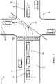
- Fig. 2 illustrates an example of one embodiment of the present invention.
- the traffic-state 20 includes a group of three vehicles stopped at an intersection in a left-turn-lane 26. While the host-vehicle 12 is the last vehicle in the group of three vehicles the detector 18 detects the traffic-signal 22 operating in a stop-state 27, as well as detecting the other vehicles ahead of the host-vehicle 12.
- the traffic-signal 22 is elevated above the center of the intersection and is configured to control traffic-flow 14 through the intersection.
- the traffic-signal 22 alternates the traffic-flow 14 between intersecting through-lanes 28 and/or turn-lanes (i.e.
- the traffic-signal 22 may be a conventional traffic-light that includes colored lamps or other indicia that accord the right-of-way to vehicles and/or pedestrians as well as a traffic-light capable of wirelessly communicating with at least the host-vehicle 12.
- the first-controller-circuit 24 requests 32 the traffic-signal 22 to operate in a proceed-state 36 until the host-vehicle 12 proceeds through the intersection by executing a left-hand-turn maneuver 38. Once the first-controller-circuit 24 determines that the host-vehicle 12 has completed the left-hand-turn maneuver 38, the first-controller-circuit 24 may request 32 the traffic-signal 22 to return to its normal operating condition.
- the system 10 may also include a second-controller-circuit 40 that is configured to operate the host-vehicle 12 in an automated mode characterized by the second-controller-circuit 40 steering the host-vehicle 12.
- first-controller-circuit 24 and second-controller circuit 40 may be separate circuity, be the same circuitry, subsystems of one another, or any combination thereof.
- the functions performed by first-controller-circuit 24 and second-controller circuit 40 may be handled by each individual controller-circuit or distributed between the two, e.g., load balancing.
- the term automated-mode is not meant to suggest that fully automated or autonomous operation of the host-vehicle 12 is required.
- the second-controller-circuit 40 may steer the host-vehicle 12 in the automated mode executing the left-hand-turn maneuver 38 through the intersection as described above.
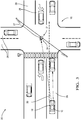
- Fig. 3 illustrates an example of one embodiment of the present invention - the example includes the traffic-state 20 where the detector 18 detects the host-vehicle 12 approaching the traffic-signal 22 (i.e. driving toward the intersection) and another vehicle stopped at the traffic-signal 22.
- the host-vehicle 12 and the other-vehicle are in a same through-lane 28.
- the detector 18 detects the traffic-signal 22 operating in the stop-state 27 for traffic-flow 14 traveling in the same direction as the host-vehicle 12.
- the first-controller-circuit 24 sends the request 32 to operate the traffic-signal 22 in the proceed-state 36 until the host-vehicle 12 proceeds through the intersection by executing a pass-through maneuver 42.
- first-controller-circuit 24 may request 32 the traffic-signal 22 to return to its normal operating condition.
- the second-controller-circuit 40 may also steer the host-vehicle 12 in the automated mode executing the pass-through maneuver 42 through the intersection as described above.
- first-controller-circuit 24 and second-controller circuit 40 may be separate circuity, be the same circuitry, subsystems of one another, or any combination thereof.
- the functions performed by first-controller-circuit 24 and second-controller circuit 40 may be handled by each individual controller-circuit or distributed between the two, e.g., load balancing.
- the first-controller-circuit 24 determines whether the traffic-signal 22 indicates the stop-state 27 and a third-controller-circuit 44 determines whether the left-hand-turn maneuver 38 (or the pass-through maneuver 42) can be completed without colliding with or impeding other traffic.
- the third-controller-circuit 44 may use data from the detector 18 and/or other sensors in communication with the system 10 to determine the local vehicle and pedestrian traffic in proximity to the intersection.
- the other sensors may be installed on the host-vehicle 12, on another vehicle, or may be part of the traffic-infrastructure, and may communicate using any communication protocol including, but not limited to, dedicated short-range communications (DSRC), or other protocols that conform to standards such as IEEE 1609, SAE J2735, SAE J2945, or Cellular V2X.
- DSRC dedicated short-range communications
- the second-controller-circuit 40 may steer the host-vehicle 12 executing the left-hand-turn maneuver 38 (or the pass-through maneuver 42) through the intersection.
- the first-controller-circuit 24 may communicate to other vehicles and/or the traffic-infrastructure the intent to perform the left-hand-turn maneuver 38 (or the pass-through maneuver 42) without the traffic-signal 22 according the right-of-way to the host-vehicle 12.
- This communication may inform the other vehicles of the event and alert the other vehicles not to follow the host-vehicle 12, as it is not uncommon for drivers of non-automated vehicles to follow a lead-vehicle through an intersection without the drivers visually checking for approaching cross-traffic.
- the first-controller-circuit 24, the second-controller-circuit 40, and the third-controller-circuit 44 may include a processor (not shown) such as a microprocessor or other control circuitry such as analog and/or digital control circuitry including an application specific integrated circuit (ASIC) for processing data as should be evident to those in the art.
- the controller-circuits may include a memory (not specifically shown), including non-volatile memory, such as electrically erasable programmable read-only memory (EEPROM) for storing one or more routines, thresholds, and captured data.
- EEPROM electrically erasable programmable read-only memory
- the one or more routines may be executed by the processors to perform steps for determining if the traffic-state 20 exists based on signals received by the first-controller-circuit 24 from the detector 18, as described above.
- the controller-circuits may be distributed throughout the host-vehicle 12 and communicate with one another through a vehicle wiring harness, or may be housed in a common enclosure. As will be appreciated, the controller-circuits may be separate circuity, be the same circuitry, subsystems of one another, or any combination thereof. As also will be appreciated, the functions performed by the controller-circuits may be handled by each individual controller-circuit or distributed between the three, e.g., load balancing.
- Fig. 4 illustrates another embodiment of a traffic control method 100.
- the traffic control method 100 is an improvement over other traffic control methods because the traffic control method 100 changes a traffic-state 20 on a roadway 16.
- Step 102 DETECT TRAFFIC-STATE, includes detecting, with a detector 18, a traffic-state 20 proximate to a host-vehicle 12 where the traffic-state 20 is characterized as inhibiting traffic-flow 14 as described above.
- the detector 18 may detect at least one vehicle stopped at a traffic-signal 22, where the traffic-signal 22 is configured to control traffic-flow 14 through an intersection.
- Step 104 DETERMINE TRAFFIC-STATE, includes determining that the traffic-state 20 has occurred, with a first-controller-circuit 24 configured to communicate with the detector 18 and the traffic-signal 22.
- Step 106 includes sending a request 32, with the first-controller-circuit 24, to the traffic-signal 22 to operate to a signal-state 34 that changes the traffic-state 20.
- the first-controller-circuit 24 may request 32 to operate the traffic-signal 22 in a proceed-state 36 until the at least one vehicle proceeds through the intersection.
- Step 108 DETERMINE DRIVING MANEUVER EXECUTION, includes determining, with a third-controller-circuit 44 in communication with the first-controller-circuit 24, whether a particular driving-maneuver may be completed without colliding with or impeding other traffic.
- the particular driving maneuvers include, but are not limited to, a left-hand-turn maneuver 38 and a pass-through maneuver 42.
- Step 110 includes steering the host-vehicle 12, with a second-controller-circuit 40 in communication with the first-controller-circuit 24, through the intersection in accordance with the determination by the third-controller-circuit 44 that the particular driving maneuver can be completed without colliding with or impeding other traffic.
- a traffic control system 10 (the system 10), controller-circuits, and a method 100 of operating the system 10 are provided.
- the system 10 is an improvement over other traffic control systems because the system 10 changes the traffic-state 20, which may improve overall traffic-flow 14 on a roadway 16.
Landscapes
- General Physics & Mathematics (AREA)
- Physics & Mathematics (AREA)
- Analytical Chemistry (AREA)
- Chemical & Material Sciences (AREA)
- Engineering & Computer Science (AREA)
- Emergency Management (AREA)
- Business, Economics & Management (AREA)
- Life Sciences & Earth Sciences (AREA)
- Atmospheric Sciences (AREA)
- Mechanical Engineering (AREA)
- Transportation (AREA)
- Automation & Control Theory (AREA)
- Multimedia (AREA)
- Theoretical Computer Science (AREA)
- Traffic Control Systems (AREA)
Abstract
Description
- This disclosure generally relates to a traffic control system, and more particularly relates to a traffic control system that changes a traffic-state.
- According to one embodiment of the invention, A traffic control system, comprises a detector configured to detect a traffic-state proximate to a host-vehicle, said traffic-state characterized as inhibiting traffic-flow; and a first-controller-circuit configured to communicate with the detector and a traffic-signal, said traffic-signal configured to control traffic-flow through an intersection, wherein the first-controller-circuit sends a request to the traffic-signal to operate to a signal-state that changes the traffic-state.
- The detector may detect at least one vehicle stopped at the traffic-signal, in accordance with the detection of the at least one vehicle stopped at the traffic-signal the first-controller-circuit sending the request to operate the traffic-signal in a proceed-state until the at least one vehicle proceeds through the intersection. The traffic control system may further comprise a second-controller-circuit steering the host-vehicle, wherein the at least one vehicle includes the host-vehicle.
- The detector may detect at least one vehicle approaching the traffic-signal, in accordance with the detection of the at least one vehicle approaching the traffic-signal the first-controller-circuit sending the request to operate the traffic-signal in a proceed-state until the at least one vehicle proceeds through the intersection.
- The traffic control system may further comprise a second-controller-circuit steering the host-vehicle, wherein the at least one vehicle includes the host-vehicle.
- The first-controller-circuit may determine whether the traffic-signal indicates a stop-state; a third-controller-circuit may determine whether a left-hand-turn maneuver can be completed without colliding with or impeding other traffic; and in accordance with the determination by the third-controller-circuit that the left-hand-turn maneuver can be completed without colliding with or impeding other traffic, a second-controller-circuit steering the host-vehicle executing the left-hand-turn maneuver (38) through the intersection.
- The first-controller-circuit may determine whether the traffic-signal indicates a stop-state; a third-controller-circuit may determine whether a pass-through maneuver can be completed without colliding with or impeding other traffic; and in accordance with the determination by the third-controller-circuit that the pass-through maneuver can be completed without colliding with or impeding other traffic, a second-controller-circuit steering the host-vehicle executing the pass-through maneuver through the intersection.
- According to the invention, a method of operating the traffic control system comprises: detecting, with a detector, a traffic-state proximate to a host-vehicle, said traffic-state characterized as inhibiting traffic-flow and requesting, with a first-controller-circuit configured to communicate with the detector and a traffic-signal, said traffic-signal configured to control traffic-flow through an intersection, the traffic-signal to operate to a signal-state that changes the traffic-state.
- The detector may detect at least one vehicle stopped at the traffic-signal, in accordance with the detection of the at least one vehicle stopped at the traffic-signal the first-controller-circuit sending the request to operate the traffic-signal in a proceed-state until the at least one vehicle proceeds through the intersection.
- The traffic control method may further comprise a second-controller-circuit steering the host-vehicle, wherein the at least one vehicle includes the host-vehicle. The detector may detect at least one vehicle approaching the traffic-signal, in accordance with the detection of the at least one vehicle approaching the traffic-signal the first-controller-circuit sending the request to operate the traffic-signal in a proceed-state until the at least one vehicle proceeds through the intersection.
- The traffic control method may further comprise a second-controller-circuit steering the host-vehicle, wherein the at least one vehicle includes the host-vehicle.
- The first-controller-circuit may determine whether the traffic-signal indicates a stop-state; a third-controller-circuit may determine whether a left-hand-turn maneuver can be completed without colliding with or impeding other traffic; and in accordance with the determination by the third-controller-circuit that the left-hand-turn maneuver can be completed without colliding with or impeding other traffic, a second-controller-circuit steering the host-vehicle executing the left-hand-turn maneuver through the intersection.
- The first-controller-circuit may determines whether the traffic-signal indicates a stop-state; a third-controller-circuit may determine whether a pass-through maneuver can be completed without colliding with or impeding other traffic; and in accordance with the determination by the third-controller-circuit that the pass-through maneuver can be completed without colliding with or impeding other traffic, a second-controller-circuit steering the host-vehicle executing the pass-through maneuver through the intersection.
- According to another embodiment of the invention, a traffic control system comprises a means of detecting a traffic-state characterized as inhibiting traffic-flow; and
a controlling means configured to communicate with the means of detecting the traffic-state and a traffic-signal, said traffic-signal configured to control traffic-flow through an intersection, wherein the controlling means sends a request to the traffic-signal to operate to a signal-state that changes the traffic-state. - The present invention will now be described, by way of example with reference to the accompanying drawings, in which:
-
Fig. 1 is an illustration of a traffic control system in accordance with one embodiment; -
Fig. 2 is an illustration of a traffic-state in accordance with one embodiment; -
Fig. 3 is an illustration of another traffic-state in accordance with one embodiment; and -
Fig. 4 is a flowchart illustrating a traffic control method in accordance with one embodiment. -
Fig. 1 illustrates a non-limiting example of atraffic control system 10, hereafter referred to as thesystem 10, installed on a host-vehicle 12. As will be described in more detail below, thesystem 10 in an improvement over other traffic control systems because thesystem 10 changes a traffic-state 20 on aroadway 16. - The
system 10 includes adetector 18 configured to detect the traffic-state 20 proximate to the host-vehicle 12 where the traffic-state 20 is characterized as inhibiting traffic-flow 14. As used herein, inhibiting traffic-flow 14 includes any scenario where traffic is moving at speeds below posted speed limits (e.g. less than 60%). In the example illustrated inFig. 1 , thedetector 18 is a camera mounted on the host-vehicle 12. In other embodiments contemplated, but not shown, the camera may be remotely mounted to a traffic-infrastructure, such as a traffic-signal 22 or a lamp-post, and in communication with the host-vehicle 12. In yet another embodiment (not shown), thedetector 18 may be a ranging-sensor, such as a radar and/or a lidar mounted to the host-vehicle 12 or remotely mounted and in communication with the host-vehicle 12. Thedetector 18 may detect indications from the traffic-signal 22, such as a color of an illuminated lamp, a position of the illuminated lamp on the traffic-signal 22, or a feature of the illuminated lamp (e.g. an arrow shape or lettering) that indicate the a right-of-way. In additional embodiments, the host-vehicle 12 receives wireless communication(s) from the traffic-signal 22 indicating the current state of the traffic-signal 22, e.g., a color of an illuminated lamp or a feature of the illuminated lamp (e.g. an arrow shape or lettering) that indicate the right-of-way. - The
system 10 also includes a first-controller-circuit 24 configured to communicate with thedetector 18 and the traffic-signal 22. Thedetector 18 may be hard-wired to the first-controller-circuit 24 in the host-vehicle 12 or may communicate through a wireless connection. The first-controller-circuit 24 may communicate with the traffic-signal 22 using any communication protocol including, but not limited to, dedicated short-range communications (DSRC), or other protocols that conform to standards such as IEEE 1609, SAE J2735, SAE J2945, or Cellular Vehicle-to-Everything ("V2X"). -
Fig. 2 illustrates an example of one embodiment of the present invention. In the example, the traffic-state 20 includes a group of three vehicles stopped at an intersection in a left-turn-lane 26. While the host-vehicle 12 is the last vehicle in the group of three vehicles thedetector 18 detects the traffic-signal 22 operating in a stop-state 27, as well as detecting the other vehicles ahead of the host-vehicle 12. The traffic-signal 22 is elevated above the center of the intersection and is configured to control traffic-flow 14 through the intersection. The traffic-signal 22 alternates the traffic-flow 14 between intersecting through-lanes 28 and/or turn-lanes (i.e. left-turn-lanes 26 and/or right-turn-lanes (not specifically shown) depending on the local traffic laws) as will be described in more detail below. The traffic-signal 22 may be a conventional traffic-light that includes colored lamps or other indicia that accord the right-of-way to vehicles and/or pedestrians as well as a traffic-light capable of wirelessly communicating with at least the host-vehicle 12. - In the example illustrated in
Fig. 2 , the first-controller-circuit 24requests 32 the traffic-signal 22 to operate in a proceed-state 36 until the host-vehicle 12 proceeds through the intersection by executing a left-hand-turn maneuver 38. Once the first-controller-circuit 24 determines that the host-vehicle 12 has completed the left-hand-turn maneuver 38, the first-controller-circuit 24 may request 32 the traffic-signal 22 to return to its normal operating condition. - The
system 10 may also include a second-controller-circuit 40 that is configured to operate the host-vehicle 12 in an automated mode characterized by the second-controller-circuit 40 steering the host-vehicle 12. As will be appreciated, first-controller-circuit 24 and second-controller circuit 40 may be separate circuity, be the same circuitry, subsystems of one another, or any combination thereof. As also will be appreciated, the functions performed by first-controller-circuit 24 and second-controller circuit 40 may be handled by each individual controller-circuit or distributed between the two, e.g., load balancing. As used herein, the term automated-mode is not meant to suggest that fully automated or autonomous operation of the host-vehicle 12 is required. It is contemplated that the teachings presented herein are applicable to instances where the host-vehicle 12 is entirely manually operated by a human and the automation is merely providing emergency vehicle controls to the human. The second-controller-circuit 40 may steer the host-vehicle 12 in the automated mode executing the left-hand-turn maneuver 38 through the intersection as described above. -
Fig. 3 illustrates an example of one embodiment of the present invention - the example includes the traffic-state 20 where thedetector 18 detects the host-vehicle 12 approaching the traffic-signal 22 (i.e. driving toward the intersection) and another vehicle stopped at the traffic-signal 22. The host-vehicle 12 and the other-vehicle are in a same through-lane 28. Thedetector 18 detects the traffic-signal 22 operating in the stop-state 27 for traffic-flow 14 traveling in the same direction as the host-vehicle 12. The first-controller-circuit 24 sends therequest 32 to operate the traffic-signal 22 in the proceed-state 36 until the host-vehicle 12 proceeds through the intersection by executing a pass-throughmaneuver 42. Once the first-controller-circuit 24 determines that the host-vehicle 12 has completed the pass-throughmaneuver 42, the first-controller-circuit 24 may request 32 the traffic-signal 22 to return to its normal operating condition. The second-controller-circuit 40 may also steer the host-vehicle 12 in the automated mode executing the pass-throughmaneuver 42 through the intersection as described above. As will be appreciated, first-controller-circuit 24 and second-controller circuit 40 may be separate circuity, be the same circuitry, subsystems of one another, or any combination thereof. As also will be appreciated, the functions performed by first-controller-circuit 24 and second-controller circuit 40 may be handled by each individual controller-circuit or distributed between the two, e.g., load balancing. - There may exist situations at intersections where the traffic-
signal 22 is unable to communicate with the first-controller-circuit 24, due to equipment limitations of the traffic-infrastructure or other communications-related issues. In such situations, the first-controller-circuit 24 determines whether the traffic-signal 22 indicates the stop-state 27 and a third-controller-circuit 44 determines whether the left-hand-turn maneuver 38 (or the pass-through maneuver 42) can be completed without colliding with or impeding other traffic. The third-controller-circuit 44 may use data from thedetector 18 and/or other sensors in communication with thesystem 10 to determine the local vehicle and pedestrian traffic in proximity to the intersection. The other sensors may be installed on the host-vehicle 12, on another vehicle, or may be part of the traffic-infrastructure, and may communicate using any communication protocol including, but not limited to, dedicated short-range communications (DSRC), or other protocols that conform to standards such as IEEE 1609, SAE J2735, SAE J2945, or Cellular V2X. In accordance with the determination by the third-controller-circuit 44 that the left-hand-turn maneuver 38 (or the pass-through maneuver 42) can be completed without colliding with or impeding other traffic, the second-controller-circuit 40 may steer the host-vehicle 12 executing the left-hand-turn maneuver 38 (or the pass-through maneuver 42) through the intersection. The first-controller-circuit 24 may communicate to other vehicles and/or the traffic-infrastructure the intent to perform the left-hand-turn maneuver 38 (or the pass-through maneuver 42) without the traffic-signal 22 according the right-of-way to the host-vehicle 12. This communication may inform the other vehicles of the event and alert the other vehicles not to follow the host-vehicle 12, as it is not uncommon for drivers of non-automated vehicles to follow a lead-vehicle through an intersection without the drivers visually checking for approaching cross-traffic. - The first-controller-
circuit 24, the second-controller-circuit 40, and the third-controller-circuit 44 (hereafter referred to collectively as the "controller-circuits") may include a processor (not shown) such as a microprocessor or other control circuitry such as analog and/or digital control circuitry including an application specific integrated circuit (ASIC) for processing data as should be evident to those in the art. The controller-circuits may include a memory (not specifically shown), including non-volatile memory, such as electrically erasable programmable read-only memory (EEPROM) for storing one or more routines, thresholds, and captured data. The one or more routines may be executed by the processors to perform steps for determining if the traffic-state 20 exists based on signals received by the first-controller-circuit 24 from thedetector 18, as described above. The controller-circuits may be distributed throughout the host-vehicle 12 and communicate with one another through a vehicle wiring harness, or may be housed in a common enclosure. As will be appreciated, the controller-circuits may be separate circuity, be the same circuitry, subsystems of one another, or any combination thereof. As also will be appreciated, the functions performed by the controller-circuits may be handled by each individual controller-circuit or distributed between the three, e.g., load balancing. -
Fig. 4 illustrates another embodiment of atraffic control method 100. Thetraffic control method 100 is an improvement over other traffic control methods because thetraffic control method 100 changes a traffic-state 20 on aroadway 16. -
Step 102, DETECT TRAFFIC-STATE, includes detecting, with adetector 18, a traffic-state 20 proximate to a host-vehicle 12 where the traffic-state 20 is characterized as inhibiting traffic-flow 14 as described above. Thedetector 18 may detect at least one vehicle stopped at a traffic-signal 22, where the traffic-signal 22 is configured to control traffic-flow 14 through an intersection. -
Step 104, DETERMINE TRAFFIC-STATE, includes determining that the traffic-state 20 has occurred, with a first-controller-circuit 24 configured to communicate with thedetector 18 and the traffic-signal 22. -
Step 106, SEND REQUEST, includes sending arequest 32, with the first-controller-circuit 24, to the traffic-signal 22 to operate to a signal-state 34 that changes the traffic-state 20. In accordance with the detection of the at least one vehicle stopped at the traffic-signal 22 the first-controller-circuit 24 may request 32 to operate the traffic-signal 22 in a proceed-state 36 until the at least one vehicle proceeds through the intersection. -
Step 108, DETERMINE DRIVING MANEUVER EXECUTION, includes determining, with a third-controller-circuit 44 in communication with the first-controller-circuit 24, whether a particular driving-maneuver may be completed without colliding with or impeding other traffic. The particular driving maneuvers include, but are not limited to, a left-hand-turn maneuver 38 and a pass-throughmaneuver 42. -
Step 110, STEER HOST-VEHICLE, includes steering the host-vehicle 12, with a second-controller-circuit 40 in communication with the first-controller-circuit 24, through the intersection in accordance with the determination by the third-controller-circuit 44 that the particular driving maneuver can be completed without colliding with or impeding other traffic. - Accordingly, a traffic control system 10 (the system 10), controller-circuits, and a
method 100 of operating thesystem 10 are provided. Thesystem 10 is an improvement over other traffic control systems because thesystem 10 changes the traffic-state 20, which may improve overall traffic-flow 14 on aroadway 16. - While this invention has been described in terms of the preferred embodiments thereof, it is not intended to be so limited, but rather only to the extent set forth in the claims that follow. Moreover, the use of the terms first, second, etc. does not denote any order of importance or operation, but rather the terms first, second, etc. are used to distinguish one element from another. Furthermore, the use of the terms a, an, etc. do not denote a limitation of quantity, but rather denote the presence of at least one of the referenced items. Additionally, directional terms such as upper, lower, etc. do not denote any particular orientation, but rather the terms upper, lower, etc. are used to distinguish one element from another and locational establish a relationship between the various elements.
Claims (14)
- A traffic control system (10), comprising:a detector (18) configured to detect a traffic-state (20) proximate to a host-vehicle (12), said traffic-state (20) characterized as inhibiting traffic-flow (14); anda first-controller-circuit (24) configured to communicate with the detector (18) and a traffic-signal (22), said traffic-signal (22) configured to control traffic-flow (14) through an intersection, wherein the first-controller-circuit (24) sends a request (32) to the traffic-signal (22) to operate to a signal-state (34) that changes the traffic-state (20).
- The traffic control system (10) in accordance with claim 1, wherein the detector (18) detects at least one vehicle stopped at the traffic-signal (22), in accordance with the detection of the at least one vehicle stopped at the traffic-signal (22) the first-controller-circuit (24) sending the request (32) to operate the traffic-signal (22) in a proceed-state (36) until the at least one vehicle proceeds through the intersection.
- The traffic control system (10) in accordance with claim 2, further comprising a second-controller-circuit (40) steering the host-vehicle (12), wherein the at least one vehicle includes the host-vehicle (12).
- The traffic control system (10) in accordance with any one of claims 1-3, wherein the detector (18) detects at least one vehicle approaching the traffic-signal (22), in accordance with the detection of the at least one vehicle approaching the traffic-signal (22) the first-controller-circuit (24) sending the request (32) to operate the traffic-signal (22) in a proceed-state (36) until the at least one vehicle proceeds through the intersection.
- The traffic control system (10) in accordance with claim 4, further comprising a second-controller-circuit (40) steering the host-vehicle (12), wherein the at least one vehicle includes the host-vehicle (12).
- The traffic control system (10) in accordance with any one of claims 1-5, wherein:the first-controller-circuit (24) determines whether the traffic-signal (22) indicates a stop-state (27);a third-controller-circuit (44) determines whether a left-hand-turn maneuver (38) can be completed without colliding with or impeding other traffic; andin accordance with the determination by the third-controller-circuit (44) that the left-hand-turn maneuver (38) can be completed without colliding with or impeding other traffic, a second-controller-circuit (40) steering the host-vehicle (12) executing the left-hand-turn maneuver (38) through the intersection.
- The traffic control system (10) in accordance with any one of claims 1-5, wherein:the first-controller-circuit (24) determines whether the traffic-signal (22) indicates a stop-state (27);a third-controller-circuit (44) determines whether a pass-through maneuver (42) can be completed without colliding with or impeding other traffic; andin accordance with the determination by the third-controller-circuit (44) that the pass-through maneuver (42) can be completed without colliding with or impeding other traffic, a second-controller-circuit (40) steering the host-vehicle (12) executing the pass-through maneuver (42) through the intersection.
- A method (100) of operating the traffic control system (10) of any one of the preceding claims, comprising:detecting (102), with the detector (18), the traffic-state (20) proximate to the host-vehicle (12), said traffic-state (20) characterized as inhibiting traffic-flow (14); andrequesting (106), with the first-controller-circuit (24) configured to communicate with the detector (18) and the traffic-signal (22), said traffic-signal (22) configured to control traffic-flow (14) through an intersection, the traffic-signal (22) to operate to the signal-state (34) that changes the traffic-state (20).
- The method (100) in accordance with claim 8, wherein the detector (18) detects (102) at least one vehicle stopped at the traffic-signal (22), in accordance with the detection of the at least one vehicle stopped at the traffic-signal (22) the first-controller-circuit (24) sending (106) the request (32) to operate the traffic-signal (22) in a proceed-state (36) until the at least one vehicle proceeds through the intersection.
- The method (100) in accordance with claim 9, further comprising a second-controller-circuit (40) steering (110) the host-vehicle (12), wherein the at least one vehicle includes the host-vehicle (12).
- The method (100) in accordance with any one of claims 8-10, wherein the detector (18) detects (102) at least one vehicle approaching the traffic-signal (22), in accordance with the detection of the at least one vehicle approaching the traffic-signal (22) the first-controller-circuit (24) sending (106) the request (32) to operate the traffic-signal (22) in a proceed-state (36) until the at least one vehicle proceeds through the intersection.
- The method (100) in accordance with claim 11, further comprising a second-controller-circuit (40) steering (110) the host-vehicle (12), wherein the at least one vehicle includes the host-vehicle (12).
- The method (100) in accordance with any one of claims 8-12, wherein:the first-controller-circuit (24) determines (104) whether the traffic-signal (22) indicates a stop-state (27);a third-controller-circuit (44) determines (108) whether a left-hand-turn maneuver (38) can be completed without colliding with or impeding other traffic; andin accordance with the determination by the third-controller-circuit (44) that the left-hand-turn maneuver (38) can be completed without colliding with or impeding other traffic, a second-controller-circuit (40) steering (110) the host-vehicle (12) executing the left-hand-turn maneuver (38) through the intersection.
- The method (100) in accordance with any one of claims 8-12, wherein:the first-controller-circuit (24) determines (104) whether the traffic-signal (22) indicates a stop-state (27);a third-controller-circuit (44) determines (108) whether a pass-through maneuver (42) can be completed without colliding with or impeding other traffic; andin accordance with the determination by the third-controller-circuit (44) that the pass-through maneuver (42) can be completed without colliding with or impeding other traffic, a second-controller-circuit (40) steering (110) the host-vehicle (12) executing the pass-through maneuver (42) through the intersection.
Applications Claiming Priority (2)
| Application Number | Priority Date | Filing Date | Title |
|---|---|---|---|
| US201862627401P | 2018-02-07 | 2018-02-07 | |
| US15/897,639 US10192433B1 (en) | 2018-02-07 | 2018-02-15 | Traffic control system |
Publications (2)
| Publication Number | Publication Date |
|---|---|
| EP3525189A1 true EP3525189A1 (en) | 2019-08-14 |
| EP3525189B1 EP3525189B1 (en) | 2024-04-03 |
Family
ID=65032193
Family Applications (1)
| Application Number | Title | Priority Date | Filing Date |
|---|---|---|---|
| EP19153508.7A Active EP3525189B1 (en) | 2018-02-07 | 2019-01-24 | Traffic control system |
Country Status (3)
| Country | Link |
|---|---|
| US (1) | US10192433B1 (en) |
| EP (1) | EP3525189B1 (en) |
| CN (1) | CN110120158B (en) |
Families Citing this family (4)
| Publication number | Priority date | Publication date | Assignee | Title |
|---|---|---|---|---|
| US11122852B2 (en) | 2018-05-31 | 2021-09-21 | Nike, Inc. | Intelligent electronic footwear and logic for navigation assistance by automated tactile, audio, and visual feedback |
| US10334906B1 (en) * | 2018-05-31 | 2019-07-02 | Nike, Inc. | Intelligent electronic footwear and control logic for automated infrastructure-based pedestrian tracking |
| CN112950941B (en) * | 2021-02-10 | 2021-09-28 | 珠海市鸿瑞信息技术股份有限公司 | Attack early warning analysis system based on big data |
| WO2022190290A1 (en) * | 2021-03-10 | 2022-09-15 | 日本電気株式会社 | Traffic signal control equipment, traffic signal device control method, and program recording medium |
Citations (7)
| Publication number | Priority date | Publication date | Assignee | Title |
|---|---|---|---|---|
| DE102007000634B3 (en) * | 2007-11-06 | 2009-04-30 | Signalbau Huber Gmbh | Traffic signal system for use in determined traffic junction, has control device determining path for vehicle at junction, where system is controlled such that lane is cleared from non-prioritized vehicles and traffic flows are blocked |
| US20090174571A1 (en) * | 2008-01-07 | 2009-07-09 | Mckenna Louis H | Navigation apparatus having emergency warning system |
| US20100309023A1 (en) * | 2009-06-05 | 2010-12-09 | Alexander Busch | Traffic Control System |
| US20110304476A1 (en) * | 2010-06-15 | 2011-12-15 | David Randal Johnson | Control of Traffic Signal Phases |
| US20150371538A1 (en) * | 2014-06-19 | 2015-12-24 | Global Traffic Technologies, Llc | Adaptive traffic signal preemption |
| US20160055746A1 (en) * | 2014-01-28 | 2016-02-25 | Hti Ip, Llc | Driver-controllable traffic signal |
| WO2017184236A1 (en) * | 2016-04-22 | 2017-10-26 | Delphi Technologies, Inc. | Automated vehicle operation based on observed movement of other vehicles |
Family Cites Families (15)
| Publication number | Priority date | Publication date | Assignee | Title |
|---|---|---|---|---|
| CH682855A5 (en) * | 1990-04-04 | 1993-11-30 | Christian Rittener Rueff | Remote control of traffic lights for emergency vehicles - has emitter in parallel with vehicle siren and which transmits digital coded signal to receiver that triggers relay to switch traffic lights to red |
| US5202683A (en) * | 1991-06-24 | 1993-04-13 | Minnesota Mining And Manufacturing Company | Optical traffic preemption detector |
| CA2178339C (en) * | 1994-01-07 | 2006-08-22 | Timothy J. Hall | Gps-based traffic control preemption system |
| CA2302998A1 (en) * | 2000-03-23 | 2001-09-23 | Harold Gordon Reeve | Emergency vehicle traffic signal control |
| DE60125249D1 (en) * | 2001-10-01 | 2007-01-25 | Dave Gross | TRAFFIC SIGNAL PREAMBLE FOR EMERGENCY VEHICLES AND COLLISION PREVENTION SYSTEM |
| JP2007506161A (en) * | 2003-09-15 | 2007-03-15 | カリフォルニア インスティテュート オブ テクノロジー | Long distance priority use and major traffic route clearance transfer system to respond to emergencies |
| CN101587648A (en) * | 2008-05-20 | 2009-11-25 | 奥城同立科技开发(北京)有限公司 | Method for controlling prior-vehicle prior-release at traffic crossing |
| CN101901549B (en) * | 2010-08-17 | 2012-07-04 | 哈尔滨工业大学 | Multi-emergency vehicle signal priority control device at single-point signalized crossing |
| CN102622901B (en) * | 2011-01-30 | 2013-12-25 | 李志恒 | Control system for providing priority signal for special vehicle and method thereof |
| CN102110372B (en) * | 2011-03-04 | 2013-04-24 | 哈尔滨工业大学 | Method for controlling signal priority of emergency vehicle at intersection based on two-stage optimization process |
| CN102402863B (en) * | 2011-10-28 | 2013-08-28 | 东南大学 | Signal priority control system and method for ensuring bus circulation |
| CN102521993B (en) * | 2011-12-23 | 2014-04-30 | 北京易华录信息技术股份有限公司 | Specific vehicle crossing signal priority control system and method thereof |
| CN103035129B (en) * | 2012-12-19 | 2014-06-25 | 江苏省智通交通科技有限公司 | Special vehicle signal priority control method based on global position system (GPS) |
| CN104064042B (en) * | 2014-07-02 | 2017-01-25 | 重庆市城投金卡信息产业股份有限公司 | Intelligent traffic management method and intelligent traffic management system supporting emergency rescue |
| CN104240525B (en) * | 2014-08-28 | 2016-03-16 | 公安部交通管理科学研究所 | There is the road traffic signal controller system of tramcar priority control function |
-
2018
- 2018-02-15 US US15/897,639 patent/US10192433B1/en active Active
-
2019
- 2019-01-24 EP EP19153508.7A patent/EP3525189B1/en active Active
- 2019-02-01 CN CN201910105455.2A patent/CN110120158B/en active Active
Patent Citations (7)
| Publication number | Priority date | Publication date | Assignee | Title |
|---|---|---|---|---|
| DE102007000634B3 (en) * | 2007-11-06 | 2009-04-30 | Signalbau Huber Gmbh | Traffic signal system for use in determined traffic junction, has control device determining path for vehicle at junction, where system is controlled such that lane is cleared from non-prioritized vehicles and traffic flows are blocked |
| US20090174571A1 (en) * | 2008-01-07 | 2009-07-09 | Mckenna Louis H | Navigation apparatus having emergency warning system |
| US20100309023A1 (en) * | 2009-06-05 | 2010-12-09 | Alexander Busch | Traffic Control System |
| US20110304476A1 (en) * | 2010-06-15 | 2011-12-15 | David Randal Johnson | Control of Traffic Signal Phases |
| US20160055746A1 (en) * | 2014-01-28 | 2016-02-25 | Hti Ip, Llc | Driver-controllable traffic signal |
| US20150371538A1 (en) * | 2014-06-19 | 2015-12-24 | Global Traffic Technologies, Llc | Adaptive traffic signal preemption |
| WO2017184236A1 (en) * | 2016-04-22 | 2017-10-26 | Delphi Technologies, Inc. | Automated vehicle operation based on observed movement of other vehicles |
Also Published As
| Publication number | Publication date |
|---|---|
| US10192433B1 (en) | 2019-01-29 |
| CN110120158B (en) | 2022-05-27 |
| CN110120158A (en) | 2019-08-13 |
| EP3525189B1 (en) | 2024-04-03 |
Similar Documents
| Publication | Publication Date | Title |
|---|---|---|
| US11067987B2 (en) | Driving assistance method and driving assistance device | |
| CN111918804B (en) | Automotive driver assistance | |
| EP3296976A1 (en) | Automated-vehicle safe-stop-zone mapping system | |
| US8730260B2 (en) | Obstacle information notification apparatus for vehicle | |
| EP3525189B1 (en) | Traffic control system | |
| US11619942B2 (en) | Controlling an autonomous vehicle when the autonomous vehicle is outside of its operational design domain | |
| US10025316B1 (en) | Automated vehicle safe stop zone use notification system | |
| EP3399330A1 (en) | Visually obstructed object detection for automated vehicle using v2v/v2i communications | |
| EP3158549B1 (en) | Adaptive traffic signal preemption | |
| CN104106103A (en) | driving aids | |
| US20180156625A1 (en) | Automated-vehicle pickup-location evaluation system | |
| US20210383693A1 (en) | Device and method for controlling vehicle | |
| EP3436324A1 (en) | Cooperative automated vehicle system | |
| KR101362706B1 (en) | Method for runnability ensuring the vhicle's straight in complex lanes system | |
| US11488476B2 (en) | Detection system and method | |
| CN103562979B (en) | Road-to-vehicle communication system and driving support system | |
| EP3483022B1 (en) | Travel control method and travel control device | |
| EP3524935B1 (en) | Vehicle perception-data gathering system and method | |
| JP5200568B2 (en) | In-vehicle device, vehicle running support system | |
| WO2017146881A1 (en) | Conflict-resolution system for operating an automated vehicle | |
| CN109671296B (en) | Automated Vehicle Safety System to Protect Pedestrians | |
| EP3560785A1 (en) | System and method to notify operator of host-vehicle of takeover-event in another-vehicle | |
| CN112740220A (en) | System and method for traffic light identification | |
| CN105599767A (en) | Roundabout detecting arrangement | |
| EP3379201A1 (en) | Automated vehicle safe stop zone use notification system |
Legal Events
| Date | Code | Title | Description |
|---|---|---|---|
| PUAI | Public reference made under article 153(3) epc to a published international application that has entered the european phase |
Free format text: ORIGINAL CODE: 0009012 |
|
| STAA | Information on the status of an ep patent application or granted ep patent |
Free format text: STATUS: THE APPLICATION HAS BEEN PUBLISHED |
|
| AK | Designated contracting states |
Kind code of ref document: A1 Designated state(s): AL AT BE BG CH CY CZ DE DK EE ES FI FR GB GR HR HU IE IS IT LI LT LU LV MC MK MT NL NO PL PT RO RS SE SI SK SM TR |
|
| AX | Request for extension of the european patent |
Extension state: BA ME |
|
| STAA | Information on the status of an ep patent application or granted ep patent |
Free format text: STATUS: REQUEST FOR EXAMINATION WAS MADE |
|
| 17P | Request for examination filed |
Effective date: 20200213 |
|
| RBV | Designated contracting states (corrected) |
Designated state(s): AL AT BE BG CH CY CZ DE DK EE ES FI FR GB GR HR HU IE IS IT LI LT LU LV MC MK MT NL NO PL PT RO RS SE SI SK SM TR |
|
| STAA | Information on the status of an ep patent application or granted ep patent |
Free format text: STATUS: EXAMINATION IS IN PROGRESS |
|
| 17Q | First examination report despatched |
Effective date: 20210709 |
|
| RAP3 | Party data changed (applicant data changed or rights of an application transferred) |
Owner name: APTIV TECHNOLOGIES LIMITED |
|
| REG | Reference to a national code |
Ref country code: DE Ref legal event code: R079 Free format text: PREVIOUS MAIN CLASS: G08G0001010000 Ipc: G08G0001087000 Ref document number: 602019049281 Country of ref document: DE |
|
| RIC1 | Information provided on ipc code assigned before grant |
Ipc: G06V 20/58 20220101ALI20230912BHEP Ipc: G08G 1/0967 20060101ALI20230912BHEP Ipc: G08G 1/0965 20060101ALI20230912BHEP Ipc: G08G 1/0962 20060101ALI20230912BHEP Ipc: G08G 1/01 20060101ALI20230912BHEP Ipc: G08G 1/087 20060101AFI20230912BHEP |
|
| GRAP | Despatch of communication of intention to grant a patent |
Free format text: ORIGINAL CODE: EPIDOSNIGR1 |
|
| STAA | Information on the status of an ep patent application or granted ep patent |
Free format text: STATUS: GRANT OF PATENT IS INTENDED |
|
| INTG | Intention to grant announced |
Effective date: 20231024 |
|
| GRAS | Grant fee paid |
Free format text: ORIGINAL CODE: EPIDOSNIGR3 |
|
| GRAA | (expected) grant |
Free format text: ORIGINAL CODE: 0009210 |
|
| STAA | Information on the status of an ep patent application or granted ep patent |
Free format text: STATUS: THE PATENT HAS BEEN GRANTED |
|
| P01 | Opt-out of the competence of the unified patent court (upc) registered |
Effective date: 20240205 |
|
| AK | Designated contracting states |
Kind code of ref document: B1 Designated state(s): AL AT BE BG CH CY CZ DE DK EE ES FI FR GB GR HR HU IE IS IT LI LT LU LV MC MK MT NL NO PL PT RO RS SE SI SK SM TR |
|
| REG | Reference to a national code |
Ref country code: GB Ref legal event code: FG4D |
|
| REG | Reference to a national code |
Ref country code: CH Ref legal event code: EP |
|
| REG | Reference to a national code |
Ref country code: IE Ref legal event code: FG4D |
|
| REG | Reference to a national code |
Ref country code: DE Ref legal event code: R096 Ref document number: 602019049281 Country of ref document: DE |
|
| REG | Reference to a national code |
Ref country code: LT Ref legal event code: MG9D |
|
| REG | Reference to a national code |
Ref country code: NL Ref legal event code: MP Effective date: 20240403 |
|
| REG | Reference to a national code |
Ref country code: AT Ref legal event code: MK05 Ref document number: 1673243 Country of ref document: AT Kind code of ref document: T Effective date: 20240403 |
|
| PG25 | Lapsed in a contracting state [announced via postgrant information from national office to epo] |
Ref country code: NL Free format text: LAPSE BECAUSE OF FAILURE TO SUBMIT A TRANSLATION OF THE DESCRIPTION OR TO PAY THE FEE WITHIN THE PRESCRIBED TIME-LIMIT Effective date: 20240403 |
|
| PG25 | Lapsed in a contracting state [announced via postgrant information from national office to epo] |
Ref country code: NL Free format text: LAPSE BECAUSE OF FAILURE TO SUBMIT A TRANSLATION OF THE DESCRIPTION OR TO PAY THE FEE WITHIN THE PRESCRIBED TIME-LIMIT Effective date: 20240403 |
|
| PG25 | Lapsed in a contracting state [announced via postgrant information from national office to epo] |
Ref country code: IS Free format text: LAPSE BECAUSE OF FAILURE TO SUBMIT A TRANSLATION OF THE DESCRIPTION OR TO PAY THE FEE WITHIN THE PRESCRIBED TIME-LIMIT Effective date: 20240803 |
|
| PG25 | Lapsed in a contracting state [announced via postgrant information from national office to epo] |
Ref country code: BG Free format text: LAPSE BECAUSE OF FAILURE TO SUBMIT A TRANSLATION OF THE DESCRIPTION OR TO PAY THE FEE WITHIN THE PRESCRIBED TIME-LIMIT Effective date: 20240403 |
|
| PG25 | Lapsed in a contracting state [announced via postgrant information from national office to epo] |
Ref country code: HR Free format text: LAPSE BECAUSE OF FAILURE TO SUBMIT A TRANSLATION OF THE DESCRIPTION OR TO PAY THE FEE WITHIN THE PRESCRIBED TIME-LIMIT Effective date: 20240403 Ref country code: FI Free format text: LAPSE BECAUSE OF FAILURE TO SUBMIT A TRANSLATION OF THE DESCRIPTION OR TO PAY THE FEE WITHIN THE PRESCRIBED TIME-LIMIT Effective date: 20240403 |
|
| PG25 | Lapsed in a contracting state [announced via postgrant information from national office to epo] |
Ref country code: GR Free format text: LAPSE BECAUSE OF FAILURE TO SUBMIT A TRANSLATION OF THE DESCRIPTION OR TO PAY THE FEE WITHIN THE PRESCRIBED TIME-LIMIT Effective date: 20240704 |
|
| PG25 | Lapsed in a contracting state [announced via postgrant information from national office to epo] |
Ref country code: PT Free format text: LAPSE BECAUSE OF FAILURE TO SUBMIT A TRANSLATION OF THE DESCRIPTION OR TO PAY THE FEE WITHIN THE PRESCRIBED TIME-LIMIT Effective date: 20240805 |
|
| PG25 | Lapsed in a contracting state [announced via postgrant information from national office to epo] |
Ref country code: ES Free format text: LAPSE BECAUSE OF FAILURE TO SUBMIT A TRANSLATION OF THE DESCRIPTION OR TO PAY THE FEE WITHIN THE PRESCRIBED TIME-LIMIT Effective date: 20240403 |
|
| PG25 | Lapsed in a contracting state [announced via postgrant information from national office to epo] |
Ref country code: CZ Free format text: LAPSE BECAUSE OF FAILURE TO SUBMIT A TRANSLATION OF THE DESCRIPTION OR TO PAY THE FEE WITHIN THE PRESCRIBED TIME-LIMIT Effective date: 20240403 |
|
| PG25 | Lapsed in a contracting state [announced via postgrant information from national office to epo] |
Ref country code: AT Free format text: LAPSE BECAUSE OF FAILURE TO SUBMIT A TRANSLATION OF THE DESCRIPTION OR TO PAY THE FEE WITHIN THE PRESCRIBED TIME-LIMIT Effective date: 20240403 |
|
| PG25 | Lapsed in a contracting state [announced via postgrant information from national office to epo] |
Ref country code: PL Free format text: LAPSE BECAUSE OF FAILURE TO SUBMIT A TRANSLATION OF THE DESCRIPTION OR TO PAY THE FEE WITHIN THE PRESCRIBED TIME-LIMIT Effective date: 20240403 |
|
| PG25 | Lapsed in a contracting state [announced via postgrant information from national office to epo] |
Ref country code: LV Free format text: LAPSE BECAUSE OF FAILURE TO SUBMIT A TRANSLATION OF THE DESCRIPTION OR TO PAY THE FEE WITHIN THE PRESCRIBED TIME-LIMIT Effective date: 20240403 |
|
| PG25 | Lapsed in a contracting state [announced via postgrant information from national office to epo] |
Ref country code: PT Free format text: LAPSE BECAUSE OF FAILURE TO SUBMIT A TRANSLATION OF THE DESCRIPTION OR TO PAY THE FEE WITHIN THE PRESCRIBED TIME-LIMIT Effective date: 20240805 Ref country code: PL Free format text: LAPSE BECAUSE OF FAILURE TO SUBMIT A TRANSLATION OF THE DESCRIPTION OR TO PAY THE FEE WITHIN THE PRESCRIBED TIME-LIMIT Effective date: 20240403 Ref country code: NO Free format text: LAPSE BECAUSE OF FAILURE TO SUBMIT A TRANSLATION OF THE DESCRIPTION OR TO PAY THE FEE WITHIN THE PRESCRIBED TIME-LIMIT Effective date: 20240703 Ref country code: LV Free format text: LAPSE BECAUSE OF FAILURE TO SUBMIT A TRANSLATION OF THE DESCRIPTION OR TO PAY THE FEE WITHIN THE PRESCRIBED TIME-LIMIT Effective date: 20240403 Ref country code: IS Free format text: LAPSE BECAUSE OF FAILURE TO SUBMIT A TRANSLATION OF THE DESCRIPTION OR TO PAY THE FEE WITHIN THE PRESCRIBED TIME-LIMIT Effective date: 20240803 Ref country code: HR Free format text: LAPSE BECAUSE OF FAILURE TO SUBMIT A TRANSLATION OF THE DESCRIPTION OR TO PAY THE FEE WITHIN THE PRESCRIBED TIME-LIMIT Effective date: 20240403 Ref country code: GR Free format text: LAPSE BECAUSE OF FAILURE TO SUBMIT A TRANSLATION OF THE DESCRIPTION OR TO PAY THE FEE WITHIN THE PRESCRIBED TIME-LIMIT Effective date: 20240704 Ref country code: FI Free format text: LAPSE BECAUSE OF FAILURE TO SUBMIT A TRANSLATION OF THE DESCRIPTION OR TO PAY THE FEE WITHIN THE PRESCRIBED TIME-LIMIT Effective date: 20240403 Ref country code: ES Free format text: LAPSE BECAUSE OF FAILURE TO SUBMIT A TRANSLATION OF THE DESCRIPTION OR TO PAY THE FEE WITHIN THE PRESCRIBED TIME-LIMIT Effective date: 20240403 Ref country code: CZ Free format text: LAPSE BECAUSE OF FAILURE TO SUBMIT A TRANSLATION OF THE DESCRIPTION OR TO PAY THE FEE WITHIN THE PRESCRIBED TIME-LIMIT Effective date: 20240403 Ref country code: BG Free format text: LAPSE BECAUSE OF FAILURE TO SUBMIT A TRANSLATION OF THE DESCRIPTION OR TO PAY THE FEE WITHIN THE PRESCRIBED TIME-LIMIT Effective date: 20240403 Ref country code: AT Free format text: LAPSE BECAUSE OF FAILURE TO SUBMIT A TRANSLATION OF THE DESCRIPTION OR TO PAY THE FEE WITHIN THE PRESCRIBED TIME-LIMIT Effective date: 20240403 Ref country code: RS Free format text: LAPSE BECAUSE OF FAILURE TO SUBMIT A TRANSLATION OF THE DESCRIPTION OR TO PAY THE FEE WITHIN THE PRESCRIBED TIME-LIMIT Effective date: 20240703 |
|
| REG | Reference to a national code |
Ref country code: DE Ref legal event code: R097 Ref document number: 602019049281 Country of ref document: DE |
|
| PG25 | Lapsed in a contracting state [announced via postgrant information from national office to epo] |
Ref country code: DK Free format text: LAPSE BECAUSE OF FAILURE TO SUBMIT A TRANSLATION OF THE DESCRIPTION OR TO PAY THE FEE WITHIN THE PRESCRIBED TIME-LIMIT Effective date: 20240403 |
|
| PG25 | Lapsed in a contracting state [announced via postgrant information from national office to epo] |
Ref country code: EE Free format text: LAPSE BECAUSE OF FAILURE TO SUBMIT A TRANSLATION OF THE DESCRIPTION OR TO PAY THE FEE WITHIN THE PRESCRIBED TIME-LIMIT Effective date: 20240403 |
|
| PG25 | Lapsed in a contracting state [announced via postgrant information from national office to epo] |
Ref country code: RO Free format text: LAPSE BECAUSE OF FAILURE TO SUBMIT A TRANSLATION OF THE DESCRIPTION OR TO PAY THE FEE WITHIN THE PRESCRIBED TIME-LIMIT Effective date: 20240403 Ref country code: SK Free format text: LAPSE BECAUSE OF FAILURE TO SUBMIT A TRANSLATION OF THE DESCRIPTION OR TO PAY THE FEE WITHIN THE PRESCRIBED TIME-LIMIT Effective date: 20240403 |
|
| PG25 | Lapsed in a contracting state [announced via postgrant information from national office to epo] |
Ref country code: SM Free format text: LAPSE BECAUSE OF FAILURE TO SUBMIT A TRANSLATION OF THE DESCRIPTION OR TO PAY THE FEE WITHIN THE PRESCRIBED TIME-LIMIT Effective date: 20240403 |
|
| PG25 | Lapsed in a contracting state [announced via postgrant information from national office to epo] |
Ref country code: SM Free format text: LAPSE BECAUSE OF FAILURE TO SUBMIT A TRANSLATION OF THE DESCRIPTION OR TO PAY THE FEE WITHIN THE PRESCRIBED TIME-LIMIT Effective date: 20240403 Ref country code: SK Free format text: LAPSE BECAUSE OF FAILURE TO SUBMIT A TRANSLATION OF THE DESCRIPTION OR TO PAY THE FEE WITHIN THE PRESCRIBED TIME-LIMIT Effective date: 20240403 Ref country code: RO Free format text: LAPSE BECAUSE OF FAILURE TO SUBMIT A TRANSLATION OF THE DESCRIPTION OR TO PAY THE FEE WITHIN THE PRESCRIBED TIME-LIMIT Effective date: 20240403 Ref country code: EE Free format text: LAPSE BECAUSE OF FAILURE TO SUBMIT A TRANSLATION OF THE DESCRIPTION OR TO PAY THE FEE WITHIN THE PRESCRIBED TIME-LIMIT Effective date: 20240403 Ref country code: DK Free format text: LAPSE BECAUSE OF FAILURE TO SUBMIT A TRANSLATION OF THE DESCRIPTION OR TO PAY THE FEE WITHIN THE PRESCRIBED TIME-LIMIT Effective date: 20240403 |
|
| PLBE | No opposition filed within time limit |
Free format text: ORIGINAL CODE: 0009261 |
|
| STAA | Information on the status of an ep patent application or granted ep patent |
Free format text: STATUS: NO OPPOSITION FILED WITHIN TIME LIMIT |
|
| 26N | No opposition filed |
Effective date: 20250106 |
|
| PG25 | Lapsed in a contracting state [announced via postgrant information from national office to epo] |
Ref country code: SI Free format text: LAPSE BECAUSE OF FAILURE TO SUBMIT A TRANSLATION OF THE DESCRIPTION OR TO PAY THE FEE WITHIN THE PRESCRIBED TIME-LIMIT Effective date: 20240403 |
|
| REG | Reference to a national code |
Ref country code: DE Ref legal event code: R081 Ref document number: 602019049281 Country of ref document: DE Owner name: APTIV TECHNOLOGIES AG, CH Free format text: FORMER OWNER: APTIV TECHNOLOGIES LIMITED, ST. MICHAEL, BB |
|
| REG | Reference to a national code |
Ref country code: CH Ref legal event code: PL |
|
| PG25 | Lapsed in a contracting state [announced via postgrant information from national office to epo] |
Ref country code: SE Free format text: LAPSE BECAUSE OF FAILURE TO SUBMIT A TRANSLATION OF THE DESCRIPTION OR TO PAY THE FEE WITHIN THE PRESCRIBED TIME-LIMIT Effective date: 20240403 |
|
| PG25 | Lapsed in a contracting state [announced via postgrant information from national office to epo] |
Ref country code: MC Free format text: LAPSE BECAUSE OF FAILURE TO SUBMIT A TRANSLATION OF THE DESCRIPTION OR TO PAY THE FEE WITHIN THE PRESCRIBED TIME-LIMIT Effective date: 20240403 Ref country code: LU Free format text: LAPSE BECAUSE OF NON-PAYMENT OF DUE FEES Effective date: 20250124 |
|
| PG25 | Lapsed in a contracting state [announced via postgrant information from national office to epo] |
Ref country code: BE Free format text: LAPSE BECAUSE OF NON-PAYMENT OF DUE FEES Effective date: 20250131 |
|
| PG25 | Lapsed in a contracting state [announced via postgrant information from national office to epo] |
Ref country code: CH Free format text: LAPSE BECAUSE OF NON-PAYMENT OF DUE FEES Effective date: 20250131 |
|
| REG | Reference to a national code |
Ref country code: BE Ref legal event code: MM Effective date: 20250131 |
|
| PG25 | Lapsed in a contracting state [announced via postgrant information from national office to epo] |
Ref country code: IE Free format text: LAPSE BECAUSE OF NON-PAYMENT OF DUE FEES Effective date: 20250124 |
|
| PG25 | Lapsed in a contracting state [announced via postgrant information from national office to epo] |
Ref country code: IT Free format text: LAPSE BECAUSE OF FAILURE TO SUBMIT A TRANSLATION OF THE DESCRIPTION OR TO PAY THE FEE WITHIN THE PRESCRIBED TIME-LIMIT Effective date: 20240403 |
|
| PGFP | Annual fee paid to national office [announced via postgrant information from national office to epo] |
Ref country code: GB Payment date: 20260112 Year of fee payment: 8 |
|
| PGFP | Annual fee paid to national office [announced via postgrant information from national office to epo] |
Ref country code: DE Payment date: 20251217 Year of fee payment: 8 |
|
| PGFP | Annual fee paid to national office [announced via postgrant information from national office to epo] |
Ref country code: FR Payment date: 20260107 Year of fee payment: 8 |