EP3525029A1 - Variable power optical system, optical device, and production method for variable power optical system - Google Patents
Variable power optical system, optical device, and production method for variable power optical system Download PDFInfo
- Publication number
- EP3525029A1 EP3525029A1 EP17858485.0A EP17858485A EP3525029A1 EP 3525029 A1 EP3525029 A1 EP 3525029A1 EP 17858485 A EP17858485 A EP 17858485A EP 3525029 A1 EP3525029 A1 EP 3525029A1
- Authority
- EP
- European Patent Office
- Prior art keywords
- lens group
- lens
- negative
- negative lens
- group
- Prior art date
- Legal status (The legal status is an assumption and is not a legal conclusion. Google has not performed a legal analysis and makes no representation as to the accuracy of the status listed.)
- Granted
Links
Images

























































Classifications
-
- G—PHYSICS
- G02—OPTICS
- G02B—OPTICAL ELEMENTS, SYSTEMS OR APPARATUS
- G02B15/00—Optical objectives with means for varying the magnification
- G02B15/14—Optical objectives with means for varying the magnification by axial movement of one or more lenses or groups of lenses relative to the image plane for continuously varying the equivalent focal length of the objective
- G02B15/16—Optical objectives with means for varying the magnification by axial movement of one or more lenses or groups of lenses relative to the image plane for continuously varying the equivalent focal length of the objective with interdependent non-linearly related movements between one lens or lens group, and another lens or lens group
- G02B15/20—Optical objectives with means for varying the magnification by axial movement of one or more lenses or groups of lenses relative to the image plane for continuously varying the equivalent focal length of the objective with interdependent non-linearly related movements between one lens or lens group, and another lens or lens group having an additional movable lens or lens group for varying the objective focal length
-
- G—PHYSICS
- G02—OPTICS
- G02B—OPTICAL ELEMENTS, SYSTEMS OR APPARATUS
- G02B15/00—Optical objectives with means for varying the magnification
- G02B15/14—Optical objectives with means for varying the magnification by axial movement of one or more lenses or groups of lenses relative to the image plane for continuously varying the equivalent focal length of the objective
- G02B15/16—Optical objectives with means for varying the magnification by axial movement of one or more lenses or groups of lenses relative to the image plane for continuously varying the equivalent focal length of the objective with interdependent non-linearly related movements between one lens or lens group, and another lens or lens group
- G02B15/177—Optical objectives with means for varying the magnification by axial movement of one or more lenses or groups of lenses relative to the image plane for continuously varying the equivalent focal length of the objective with interdependent non-linearly related movements between one lens or lens group, and another lens or lens group having a negative front lens or group of lenses
-
- G—PHYSICS
- G02—OPTICS
- G02B—OPTICAL ELEMENTS, SYSTEMS OR APPARATUS
- G02B13/00—Optical objectives specially designed for the purposes specified below
- G02B13/18—Optical objectives specially designed for the purposes specified below with lenses having one or more non-spherical faces, e.g. for reducing geometrical aberration
-
- G—PHYSICS
- G02—OPTICS
- G02B—OPTICAL ELEMENTS, SYSTEMS OR APPARATUS
- G02B27/00—Optical systems or apparatus not provided for by any of the groups G02B1/00 - G02B26/00, G02B30/00
- G02B27/64—Imaging systems using optical elements for stabilisation of the lateral and angular position of the image
- G02B27/646—Imaging systems using optical elements for stabilisation of the lateral and angular position of the image compensating for small deviations, e.g. due to vibration or shake
Definitions
- the present invention relates to a zoom optical system, optical apparatus using the zoom optical system, and a method for manufacturing the zoom optical system.
- Patent literature 1 Japanese Laid-Open Patent Publication No. 11-316342(A )
- a zoom optical system comprises: a first negative lens group having a negative refractive power; and a second negative lens group disposed closer to an image than the first negative lens group, and a distance between the first negative lens group and the second negative lens group changes during zooming, and the first negative lens group is movable so that at least a part thereof has a displacement component in a direction perpendicular to the optical axis. At least a part of the second negative lens group is movable along the optical axis during focusing.
- a zoom optical system comprises: a first lens group having a positive refractive power, a second lens group disposed closer to an image than the first lens group and having a negative refractive power, a third lens group disposed closer to an image than the second lens group and having a positive refractive power, and a fourth lens group disposed closer to an image than the third lens group and having a negative refractive power, and a distance between the first lens group and the second lens group changes, a distance between the second lens group and the third lens group changes, a distance between the third lens group and the fourth lens group changes during zooming, the second lens group includes at least partly a vibration proof group movable so as to have a displacement component in a direction perpendicular to an optical axis, the fourth lens group includes a positive lens and a negative lens disposed in order from an object, an air distance is present between the positive lens and the negative lens, and the following conditional expressions, 0.001 ⁇ Dpn / ⁇ f 4 ⁇ 0.
- a zoom optical system comprises: a first lens group having a positive refractive power, a second lens group disposed closer to an image than the first lens group and having a negative refractive power, a third lens group disposed closer to an image than the second lens group and having a positive refractive power, and a following group (or succeeding group) disposed closer to an image than the third lens group and consisting of at least one lens group, and a distance between the first lens group and the second lens group changes, a distance between the second lens group and the third lens group changes, a distance between the third lens group and the following group changes during zooming, any one of the first lens group, the second lens group, the third lens group, and the following group includes at least partly a vibration proof group movable so as to have a displacement component in a direction perpendicular to an optical axis, the vibration proof group consists of a positive lens, a first negative lens, and a second negative lens disposed in order from an object, an air distance is present between the positive
- An optical apparatus includes the zoom optical system mounted thereon.
- a method for manufacturing a zoom optical system is a method of manufacturing a zoom optical system comprising: a first negative lens group having a negative refractive power; and a second negative lens group disposed closer to an image than the first negative lens group, and a distance between the first negative lens group and the second negative lens group changes during zooming, the first negative lens group is movable at least partly so as to have a displacement component in a direction perpendicular to an optical axis, at least part of the second negative lens group is movable along the optical axis during focusing, and each lens is disposed within a lens barrel so as to satisfy the following conditional expression, 0.50 ⁇ fGb / fGa ⁇ 2.60 where,
- a method for manufacturing a zoom optical system is a method of manufacturing a zoom optical system comprising: a first lens group having a positive refractive power, a second lens group disposed closer to an image than the first lens group and having a negative refractive power, a third lens group disposed closer to an image than the second lens group and having a positive refractive power, and a fourth lens group disposed closer to an image than the third lens group and having a negative refractive power, and a distance between the first lens group and the second lens group changes, a distance between the second lens group and the third lens group changes, a distance between the third lens group and the fourth lens group changes during zooming, the second lens group includes at least partly a vibration proof group movable so as to have a displacement component in a direction perpendicular to an optical axis, the fourth lens group includes a positive lens and a negative lens disposed in order from an object, an air distance is present between the positive lens and the negative lens, and each lens is disposed within a
- a method for manufacturing a zoom optical system is a method of manufacturing a zoom optical system comprising: a first lens group having a positive refractive power, a second lens group disposed closer to an image than the first lens group and having a negative refractive power, a third lens group disposed closer to an image than the second lens group and having a positive refractive power, and a following group disposed closer to an image than the third lens group and consisting of at least one lens group, and a distance between the first lens group and the second lens group changes, a distance between the second lens group and the third lens group changes, a distance between the third lens group and the following group changes during zooming, any one of the first lens group, the second lens group, the third lens group, and the following group includes at least partly a vibration proof group movable so as to have a displacement component in a direction perpendicular to an optical axis, the vibration proof group consists of a positive lens, a first negative lens, and a second negative lens disposed in order from
- a zoom optical system ZL (1) as an example of the zoom optical system (zoom lens) ZL according to the first embodiment includes: as illustrated in FIG. 1 , a first negative lens group (second lens group G2) having a negative refractive power, and a second negative lens group (fourth lens group G4) disposed closer to an image than the first negative lens group.
- a distance between the first negative lens group and the second negative lens group changes.
- At least part of the first negative lens group is movable so as to have a displacement component in a direction perpendicular to an optical axis.
- At least part of the second negative lens group is movable along the optical axis during focusing.
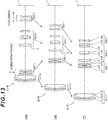
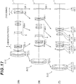
- the zoom optical system ZL according to the first embodiment may be a zoom optical system ZL (2) illustrated in FIG. 5 , may be a zoom optical system ZL (3) illustrated in FIG. 9 ; may be a zoom optical system ZL (4) illustrated in FIG. 13 ; may be a zoom optical system ZL (5) illustrated in FIG. 17 ; and may be a zoom optical system ZL (6) illustrated in FIG. 21 .
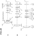
- the zoom optical system ZL of the first embodiment may be a zoom optical system ZL (7) illustrated in FIG. 25 ; may be a zoom optical system ZL (8) illustrated in FIG. 29 ; may be a zoom optical system ZL (9) illustrated in FIG. 33 ; may be a zoom optical system ZL (10) illustrated in FIG.
- zoom optical system ZL (11) illustrated in FIG. 41 .
- groups from the zoom optical system ZL (2) to ZL (11) illustrated in FIG. 5 or other drawings are configured in the same manner as the zoom optical system ZL (1) illustrated in FIG. 1 .
- the zoom optical system ZL according to the first embodiment having the configuration described above satisfies the following conditional expression. Accordingly, an optical performance in a wide angle end state is improved, and thus a telephoto type zoom optical system having a wider angle of view is achieved.
- a zoom optical system suitable for imaging a video 0.50 ⁇ fGb / fGa ⁇ 2.60 where,
- the conditional expression (1) is a conditional expression for defining an adequate range for a ratio of focal lengths between the second negative lens group (fourth lens group G4) and the first negative lens group (second lens group G2).
- a corresponding value of the conditional expression (1) exceeds an upper limit value, the power (refractive power) of the first negative lens group is too much stronger than the power of the second negative lens group, which makes it difficult to correct spherical aberration and coma aberration in the telephoto end state.
- the upper limit value of the conditional expression (1) is preferably set to 2.40, and more preferably to 2.10.
- the lower limit value of the conditional expression (1) is preferably set to 0.60, and more preferably to 0.70.
- the first negative lens group (second lens group G2) preferably includes at least partly a vibration proof group movable so as to have a displacement component in a direction perpendicular to an optical axis, and satisfies the following conditional expression (2). 0.93 ⁇ fVR / fGa ⁇ 2.50 where fVR : a focal length of the vibration proof group.
- the conditional expression (2) is a conditional expression for defining an adequate range for a ratio of focal lengths between the vibration proof group and the first negative lens group (second lens group G2).
- the conditional expression (2) correction of the eccentric coma aberration and the eccentric curvature of field when the shake compensation is performed may be successfully corrected.
- the lateral chromatic aberration and the distortion in the wide angle end state may be successfully corrected.
- the power of the first negative lens group is secured without increasing the power of the vibration proof group too much so that a zooming rate may be gained. For example, a zooming rate of three times or more, preferably, a zooming rate of four times of more may be achieved.
- the upper limit value of the conditional expression (2) is preferably set to 2.10, and more preferably to 1.70.
- the lower limit value of the conditional expression (2) is preferably set to 1.00.
- the second negative lens group (fourth lens group G4) preferably comprises a positive lens and a negative lens which are disposed in order from an object, and an air distance is present between the positive lens and the negative lens, and satisfies the following conditional expression (3). 0.001 ⁇ Dpn / ⁇ fGb ⁇ 0.400 where Dpn : an air distance between the positive lens and the negative lens in the second negative lens group.
- the conditional expression (3) is a conditional expression for defining an adequate range for an air distance between the positive lens and the negative lens in the second negative lens group (fourth lens group G4). By satisfying the conditional expression (3), a successful aberration correction is achieved. In addition, since manufacture sensitivity of the second negative lens group is lowered, the zoom optical system ZL is easily manufactured.
- the upper limit value of the conditional expression (3) is preferably set to 0.300, and more preferably to 0.200.
- the lower limit value of the conditional expression (3) is preferably set to 0.003, and more preferably to 0.005.
- the first negative lens group (second lens group G2) may include at least partly a vibration proof group movable so as to have a displacement component in a direction perpendicular to an optical axis
- the vibration proof group may consist of a positive lens, a first negative lens, and a second negative lens disposed in order from an object, an air distance may be present between the positive lens and the first negative lens, and an air distance may be present between the first negative lens and the second negative lens.
- the eccentric coma aberration and the eccentric curvature of field when the shake compensation is performed may be successfully corrected.
- the lateral chromatic aberration and the distortion in the wide angle end state may be successfully corrected.
- a positive lens is disposed on an object side with respect to the first negative lens and the second negative lens, and thus reduction in diameter of the vibration proof group is enabled.
- the zoom optical system ZL according to the first embodiment includes: an intermediate lens group (third lens group G3) disposed between the first negative lens group (second lens group G2) and the second negative lens group (fourth lens group G4), and the distance between the first negative lens group and the intermediate lens group changes, and the distance between the intermediate lens group and the second negative lens group changes during zooming. Accordingly, the distance between the first negative lens group and the intermediate lens group changes, and the distance between the intermediate lens group and the second negative lens group changes during zooming, and thus a high zooming rate is obtained.
- an intermediate lens group third lens group G3 disposed between the first negative lens group (second lens group G2) and the second negative lens group (fourth lens group G4)
- the zoom optical system ZL according to the first embodiment includes: an object side lens group (first lens group G1) disposed on the object side with respect to the first negative lens group (second lens group G2) and having a positive refractive power, and the distance between the object side lens group and the first negative lens group changes during zooming. Accordingly, the distance between the object side lens group and the first negative lens group changes during zooming, and thus a high zooming rate is achieved.
- first lens group G1 disposed on the object side with respect to the first negative lens group (second lens group G2) and having a positive refractive power
- the zoom optical system ZL according to the first embodiment includes: an image side lens group (fifth lens group G5) disposed closer to an image than the second negative lens group (fourth lens group G4), and the distance between the second negative lens group and the image side lens group changes during zooming. Accordingly, the distance between the second negative lens group and the image side lens group changes during zooming, and thus a high zooming rate is achieved.
- the zoom optical system ZL according to the first embodiment includes: an intermediate lens group (third lens group G3) disposed between the first negative lens group (second lens group G2) and the second negative lens group (fourth lens group G4), and the distance between the first negative lens group and the intermediate lens group changes, and the distance between the intermediate lens group and the second negative lens group changes during zooming, and an aperture stop S is disposed between the first negative lens group and the intermediate lens group. Accordingly, the astigmatism, the coma aberration, and the lateral chromatic aberration may be successfully corrected.
- the zoom optical system ZL includes: an intermediate lens group (third lens group G3) disposed between the first negative lens group (second lens group G2) and the second negative lens group (fourth lens group G4), and the distance between the first negative lens group and the intermediate lens group changes, and the distance between the intermediate lens group and the second negative lens group changes during zooming, and the intermediate lens group consists of the object side subgroup having a positive refractive power and the image side subgroup having a positive refractive power disposed in order from an object, and when a lens component including a negative lens is disposed at a position closest to the object in the image side subgroup (in each example of the following description, the object side subgroup and the image side subgroup in such a case are referred to as first object side subgroup and first image side subgroup), the following conditional expression (4) is satisfied. 0.60 ⁇ fa / fb ⁇ 1.20 where
- the conditional expression (4) is a conditional expression for defining an adequate range for a ratio of focal lengths between the object side subgroup and the image side subgroup of the intermediate lens group (third lens group G3). By satisfying the conditional expression (4), the axial chromatic aberration and the spherical aberration are successfully corrected. It should be noted that, in each embodiment, the lens component indicates a single lens or a cemented lens.
- the upper limit value of the conditional expression (4) is preferably set to 1.00, and more preferably to 0.80.
- the lower limit value of the conditional expression (4) is preferably set to 0.08, and more preferably to 0.10.
- the zoom optical system ZL includes: an intermediate lens group (third lens group G3) disposed between the first negative lens group (second lens group G2) and the second negative lens group (fourth lens group G4), and the distance between the first negative lens group and the intermediate lens group changes, and the distance between the intermediate lens group and the second negative lens group changes during zooming, and the intermediate lens group consists of the object side subgroup having a positive refractive power and the image side subgroup having a positive refractive power disposed in order from an object, and when the air distance between the object side subgroup and the image side subgroup is the maximum air distance between the air distance between lenses in the intermediate lens group, (in each example of the following description, the object side subgroup and the image side subgroup in such a case are referred to as second object side subgroup and second image side subgroup), the following conditional expression (5) is satisfied. 0.60 ⁇ f ⁇ ⁇ / f ⁇ ⁇ 1.20 where
- the conditional expression (5) is a conditional expression for defining an adequate range for a ratio of focal lengths between the object side subgroup and the image side subgroup of the intermediate lens group (third lens group G3).
- the upper limit value of the conditional expression (5) is preferably set to 2.20, and more preferably to 1.80.
- the lower limit value of the conditional expression (5) is preferably set to 0.08, and more preferably to 0.10.
- the first negative lens group (second lens group G2) may include partly a vibration proof group movable so as to have a displacement component in a direction perpendicular to an optical axis
- the first negative lens group may consist of a negative subgroup having a negative refractive power and the vibration proof group described above and having a negative refractive power disposed in order from an object
- a lens component including a positive lens may be disposed at a position closest to the image in the vibration proof group. Accordingly, the eccentric coma aberration and the eccentric curvature of field when the shake compensation is performed may be successfully corrected. Also, the lateral chromatic aberration and the distortion in the wide angle end state may be successfully corrected.
- the zoom optical system ZL according to the first embodiment includes: an intermediate lens group (third lens group G3) disposed between the first negative lens group (second lens group G2) and the second negative lens group (fourth lens group G4), and the distance between the first negative lens group and the intermediate lens group changes, and the distance between the intermediate lens group and the second negative lens group changes during zooming, and the following conditional expression (6) is satisfied. 0.40 ⁇ fGc / ⁇ fGa ⁇ 2.60 where,
- the conditional expression (6) is a conditional expression for defining an adequate range for a ratio of focal lengths between the intermediate lens group (third lens group G3) and the first negative lens group (second lens group G2).
- a corresponding value of the conditional expression (6) exceeds an upper limit value, the power of the first negative lens group is too much stronger than the power of the intermediate lens group, which makes it difficult to correct the astigmatism in the wide angle end state.
- the upper limit value of the conditional expression (6) is preferably set to 2.20, and more preferably to 1.80.
- the lower limit value of the conditional expression (6) is preferably set to 0.55, and more preferably to 0.70.
- the zoom optical system ZL according to the first embodiment includes: an intermediate lens group (third lens group G3) disposed between the first negative lens group (second lens group G2) and the second negative lens group (fourth lens group G4), and the distance between the first negative lens group and the intermediate lens group changes, and the distance between the intermediate lens group and the second negative lens group changes during zooming, and the following conditional expression (7) is satisfied. 0.20 ⁇ fGc / ⁇ fGb ⁇ 2.40 where,
- the conditional expression (7) is a conditional expression for defining an adequate range for a ratio of focal lengths between the intermediate lens group (third lens group G3) and the second negative lens group (fourth lens group G4).
- a corresponding value of the conditional expression (7) exceeds an upper limit value, the power of the second negative lens group is too much stronger than the power of the intermediate lens group, which makes it difficult to correct the coma aberration in the wide angle end state.
- the upper limit value of the conditional expression (7) is preferably set to 2.00, and more preferably to 1.60.
- the lower limit value of the conditional expression (7) is preferably set to 0.30, and more preferably to 0.40.
- the zoom optical system ZL according to the first embodiment includes: an object side lens group (first lens group G1) disposed on the object side with respect to the first negative lens group (second lens group G2) and having a positive refractive power, and the distance between the object side lens group and the first negative lens group changes during zooming, and the following conditional expression (8) is satisfied. 0.30 ⁇ mda / fw ⁇ 2.30 where
- the conditional expression (8) is a conditional expression for defining an adequate range for variable magnification burden of the first negative lens group (second lens group G2).
- the upper limit value of the conditional expression (8) is preferably set to 1.90, and more preferably to 1.50.
- the lower limit value of the conditional expression (8) is preferably set to 0.40, and more preferably to 0.50.
- the zoom optical system ZL according to the first embodiment includes: an intermediate lens group (third lens group G3) disposed between the first negative lens group (second lens group G2) and the second negative lens group (fourth lens group G4), and the distance between the first negative lens group and the intermediate lens group changes, and the distance between the intermediate lens group and the second negative lens group changes during zooming, and the following conditional expression (9) is satisfied.
- an intermediate lens group third lens group G3 disposed between the first negative lens group (second lens group G2) and the second negative lens group (fourth lens group G4)
- the conditional expression (9) is a conditional expression for achieving both the variable magnification burden and the aberration correction effect of the second negative lens group (fourth lens group G4).
- the corresponding value of the conditional expression (9) exceeds the upper limit value, the amount of change (absolute value) in distance between the intermediate lens group (third lens group G3) and the second negative lens group (fourth lens group G4) increases. Therefore, the variable magnification burden of the second negative lens group increases, which makes it difficult to correct spherical aberration in the telephoto end state and astigmatism in the wide angle end state.
- the upper limit value of the conditional expression (9) is preferably set to 0.650, and more preferably to 0.550.
- the lower limit value of the conditional expression (9) undergoes the lower limit value, the amount of change (absolute value) in distance between the intermediate lens group and the second negative lens group decreases, and thus the aberration correction effect of change in distance between the intermediate lens group and the second negative lens group is less likely achieved. Therefore, achievement of both the aberration correction in the telephoto end state and the aberration correction in the wide angle end state is difficult, which makes it difficult to correct the spherical aberration and astigmatism in the wide angle end state.
- the lower limit value of the conditional expression (9) is preferably set to 0.065, and more preferably to 0.080.
- the zoom optical system ZL includes: an aperture stop S disposed between the first negative lens group (second lens group G2) and the second negative lens group (fourth lens group G4), and a lens group (third lens group G3) having a positive lens component disposed so as to oppose the image side of the aperture stop S, and a distance between the first negative lens group and a lens group having a positive lens component changes, a distance between the lens group having the positive lens component and the second negative lens group changes during zooming, and the following conditional expression (10) is satisfied. 0.40 ⁇ fp / fGp ⁇ 3.60 where
- the conditional expression (10) is a conditional expression defining an adequate range of a focal length of the positive lens component disposed so as to oppose the image side of the aperture stop S.
- the upper limit value of the conditional expression (10) is preferably set to 3.00, and more preferably to 2.60.
- the lower limit value of the conditional expression (10) is preferably set to 0.50, and more preferably to 0.60.
- the zoom optical system ZL includes: an aperture stop S disposed between the first negative lens group (second lens group G2) and the second negative lens group (fourth lens group G4), and a lens group (third lens group G3) having a positive lens component disposed so as to oppose the image side of the aperture stop S, and a distance between the first negative lens group and a lens group having a positive lens component changes, a distance between the lens group having the positive lens component and the second negative lens group changes during zooming, and the following conditional expression (11) is satisfied. 0.40 ⁇ LS / LGp ⁇ 0.90 where
- the conditional expression (11) is a conditional expression defining an adequate range of the thickness of the lens group having the positive lens component on the optical axis.
- the upper limit value of the conditional expression (11) is preferably set to 0.80, and more preferably to 0.70.
- the lower limit value of the conditional expression (11) is preferably set to 0.42, and more preferably to 0.435.
- the zoom optical system ZL includes: an aperture stop S disposed between the first negative lens group (second lens group G2) and the second negative lens group (fourth lens group G4), and a lens group (third lens group G3) having a positive lens component disposed so as to oppose the image side of the aperture stop S, and a distance between the first negative lens group and a lens group having a positive lens component changes, a distance between the lens group having the positive lens component and the second negative lens group changes during zooming, and at least one lens surface of the positive lens component has an aspherical surface, and the following conditional expression (12) is satisfied. 0.15 ⁇ 100 ⁇ ⁇ / ⁇ ⁇ 1.30 where
- the conditional expression (12) is a conditional expression defining an adequate range of an aspherical amount (sag amount) of the positive lens component disposed so as to oppose the image side of the aperture stop S.
- the effective diameter of the lens surface on the object side in the positive lens component or the effective diameter of the lens surface on the image side becomes the maximum effective diameter upon focusing on infinity in the telephoto end state.
- the aspherical surface may be formed only on the lens surface on the object side of the positive lens component, may be formed only on the lens surface on the image side of the positive lens component, or may be formed on lens surfaces on both sides of the positive lens component. In other words, as described above, the aspherical surface needs only be formed on at least one of the lens surfaces of the positive lens component.
- the upper limit value of the conditional expression (12) is preferably set to 1.00, and more preferably to 0.80.
- the lower limit value of the conditional expression (12) is preferably set to 0.20, and more preferably to 0.25.
- An optical apparatus is configured with the zoom optical system having a configuration described above.
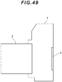
- a camera (optical apparatus) provided with the zoom optical system ZL according to the first embodiment will be described with reference to FIG. 49 .
- the camera 1 is a digital camera provided with the zoom optical system according to the embodiment described above as an imaging lens 2 as illustrated in FIG. 49 .
- light from an object (subject) not illustrated is converged by the imaging lens 2, and reaches an image pickup device 3. Accordingly, light from the subject is imaged by the image pickup device 3, and is recorded in a memory, not illustrated, as a subject image.
- a photographer is allowed to photograph the subject by the camera 1 in this manner.
- the camera may be a mirror-less camera, or may be a single lens reflex type camera having a quick return mirror.
- the zoom optical system ZL according to the first embodiment as the imaging lens, an optical apparatus having an improved optical performance in the wide angle end state and having a wider angle of view is achieved.
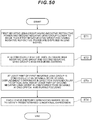
- a first negative lens group (second lens group G2) having a negative refractive power and a second negative lens group (fourth lens group G4) closer to an image than the first negative lens group and having a negative refractive power are disposed in a lens barrel (Step ST1). It is configured that the distance between the first negative lens group and the second negative lens group is changed during zooming (Step ST2).
- At least part of the first negative lens group is configured to be movable so as to have a displacement component in a direction perpendicular to the optical axis, and at least part of the second negative lens group is configured to be movable along the optical axis during focusing (Step ST3).
- each lens is arranged within a lens barrel so as to satisfy at least the aforementioned conditional expression (1) (Step ST4). According to the manufacturing method as described above, the optical performance in a wide angle end state is improved, and thus a telephoto type zoom optical system having a wider angle of view may be manufactured.
- a zoom optical system ZL (1) as an example of the zoom optical system (zoom lens) ZL according to the second embodiment comprises: as illustrated in FIG. 1 , a first lens group G1 having a positive refractive power, a second lens group G2 disposed closer to an image than the first lens group G1 and having a negative refractive power, a third lens group G3 disposed closer to an image than the second lens group G2 and having a positive refractive power, and a fourth lens group G4 disposed closer to an image than the third lens group G3 and having a negative refractive power.
- the second lens group G2 may be configured to include at least partly a vibration proof group movable so as to have a displacement component in a direction perpendicular to an optical axis.
- the fourth lens group G4 is configured to include a positive lens and a negative lens disposed in order from an object. It should be noted that an air distance is present between the positive lens and the negative lens.
- the zoom optical system ZL according to the second embodiment may be a zoom optical system ZL (2) illustrated in FIG. 5 , may be a zoom optical system ZL (3) illustrated in FIG. 9 ; may be a zoom optical system ZL (4) illustrated in FIG. 13 ; may be a zoom optical system ZL (5) illustrated in FIG. 17 ; and may be a zoom optical system ZL (6) illustrated in FIG. 21 .
- the zoom optical system ZL according to the second embodiment may be a zoom optical system ZL (7) illustrated in FIG. 25 ; may be a zoom optical system ZL (8) illustrated in FIG. 29 ; may be a zoom optical system ZL (9) illustrated in FIG. 33 ; may be a zoom optical system ZL (10) illustrated in FIG.
- zoom optical system ZL (11) illustrated in FIG. 41 .
- groups from the zoom optical system ZL (2) to ZL (11) illustrated in FIG. 5 or other drawings are configured in the same manner as the zoom optical system ZL (1) illustrated in FIG. 1 .
- the zoom optical system ZL according to the second embodiment having the configuration described above satisfies the following conditional expressions. Accordingly, a telephoto type zoom optical system having a higher zooming rate is achieved. 0.001 ⁇ Dpn / ⁇ f 4 ⁇ 0.400 0.93 ⁇ fVR / f 2 ⁇ 2.50 where
- the conditional expression (13) is a conditional expression for defining an adequate range for an air distance between the positive lens and the negative lens in the fourth lens group G4.
- the upper limit value of the conditional expression (13) is preferably set to 0.300, and more preferably to 0.200.
- the lower limit value of the conditional expression (13) is preferably set to 0.003, and more preferably to 0.005.
- the conditional expression (14) is a conditional expression for defining an adequate range for a ratio of focal lengths between the vibration proof group and the second lens group G2.
- the upper limit value of the conditional expression (14) is preferably set to 2.10, and more preferably to 1.70.
- the lower limit value of the conditional expression (14) is preferably set to 1.00.
- the zoom optical system ZL during focusing, at least part of the lenses in the fourth lens group G4 move along the optical axis. Accordingly, variations in chromatic aberration and variation in spherical aberration during focusing may be successfully corrected.
- the following conditional expression (15) is satisfied. 0.40 ⁇ f 4 / f 2 ⁇ 4.00
- the conditional expression (15) is a conditional expression for defining an adequate range for a ratio of focal lengths between the fourth lens group G4 and the second lens group G2.
- a corresponding value of the conditional expression (15) exceeds an upper limit value, the power (refractive power) of the second lens group G2 is too much stronger than the power of the fourth lens group G4, which makes it difficult to correct spherical aberration and coma aberration in the telephoto end state.
- the upper limit value of the conditional expression (15) is preferably set to 3.25, and more preferably to 2.50.
- the lower limit value of the conditional expression (15) is preferably set to 0.55, and more preferably to 0.70.
- an aperture stop S is disposed between the second lens group G2 and the third lens group G3. Accordingly, the astigmatism, the coma aberration, and the lateral chromatic aberration may be successfully corrected.
- the zoom optical system ZL when the third lens group G3 consists of an object side subgroup having a positive refractive power and an image side subgroup having a positive refractive power disposed in order from an object, and a lens component including the negative lens is disposed at a position closest to the object in the image side subgroup, (in each example of the following description, the object side subgroup and the image side subgroup in such a case are referred to as first object side subgroup and first image side subgroup), the following conditional expression (16) is satisfied. 0.06 ⁇ f 3 ⁇ a / f 3 ⁇ b ⁇ 1.20 where
- conditional expression (16) is a conditional expression for defining an adequate range for a ratio of focal lengths between the object side subgroup and the image side subgroup in the third lens group G3.
- the upper limit value of the conditional expression (16) is preferably set to 1.00, and more preferably to 0.80.
- the lower limit value of the conditional expression (16) is preferably set to 0.08, and more preferably to 0.10.
- the third lens group G3 consists of the object side subgroup having a positive refractive power and the image side subgroup having a positive refractive power disposed in order from an object, and when the air distance between the object side subgroup and the image side subgroup is the maximum air distance between the distance between lenses in the third lens group G3, (in each example of the following description, the object side subgroup and the image side subgroup in such a case are referred to as second object side subgroup and second image side subgroup), the following conditional expression (17) is satisfied. 0.06 ⁇ f 3 ⁇ ⁇ / f 3 ⁇ ⁇ ⁇ 2.60 where
- conditional expression (17) is a conditional expression for defining an adequate range for a ratio of focal lengths between the object side subgroup and the image side subgroup in the third lens group G3.
- the upper limit value of the conditional expression (17) is preferably set to 2.20, and more preferably to 1.80.
- the lower limit value of the conditional expression (17) is preferably set to 0.08, and more preferably to 0.10.
- the second lens group G2 may consist of a negative subgroup having a negative refractive power and the vibration proof group described above and having a negative refractive power disposed in order from an object, and a lens component including a positive lens may be disposed at a position closest to the image in the vibration proof group. Accordingly, the eccentric coma aberration and the eccentric curvature of field when the shake compensation is performed may be successfully corrected. Also, the lateral chromatic aberration and the distortion in the wide angle end state may be successfully corrected.
- the vibration proof group may consist of a positive lens, a first negative lens, and a second negative lens disposed in order from an object, an air distance may be present between the positive lens and the first negative lens, and an air distance may be present between the first negative lens and the second negative lens. Accordingly, the eccentric coma aberration and the eccentric curvature of field when the shake compensation is performed may be successfully corrected. Also, the lateral chromatic aberration and the distortion in the wide angle end state may be successfully corrected.
- the following conditional expression (18) is satisfied. 0.40 ⁇ f 3 / ⁇ f 2 ⁇ 2.60 where,
- the conditional expression (18) is a conditional expression for defining an adequate range for a ratio of focal lengths between the third lens group G3 and the second lens group G2.
- a corresponding value of the conditional expression (18) exceeds an upper limit value, the power of the second lens group G2 is too much stronger than the power of the third lens group G3, which makes it difficult to correct the astigmatism in the wide angle end state.
- the upper limit value of the conditional expression (18) is preferably set to 2.20, and more preferably to 1.80.
- the lower limit value of the conditional expression (18) is preferably set to 0.55, and more preferably to 0.70.
- the following conditional expression (19) is satisfied. 0.20 ⁇ f 3 / ⁇ f 4 ⁇ 2.40
- the conditional expression (19) is a conditional expression for defining an adequate range for a ratio of focal lengths between the third lens group G3 and the fourth lens group G4.
- a corresponding value of the conditional expression (19) exceeds an upper limit value, the power of the fourth lens group G4 is too much stronger than the power of the third lens group G3, which makes it difficult to correct the coma aberration in the wide angle end state.
- the upper limit value of the conditional expression (19) is preferably set to 2.00, and more preferably to 1.60.
- the lower limit value of the conditional expression (19) is preferably set to 0.30, and more preferably to 0.40.
- the following conditional expression (20) is satisfied. 0.30 ⁇ m 12 / fw ⁇ 2.30 where,
- the conditional expression (20) is a conditional expression for defining an adequate range for variable magnification burden of the second lens group G2.
- the upper limit value of the conditional expression (20) is preferably set to 1.90, and more preferably to 1.50.
- the lower limit value of the conditional expression (20) is preferably set to 0.40, and more preferably to 0.50.
- the following conditional expression (21) is satisfied. 0.050 ⁇ m 34 / fw ⁇ 0.750
- the conditional expression (21) is a conditional expression for achieving both the variable magnification burden and the aberration correction effect of the fourth lens group G4.
- the corresponding value of the conditional expression (21) exceeds the upper limit value, the amount of change (absolute value) in distance between the third lens group G3 and the fourth lens group G4 increases. Therefore, the variable magnification burden of the fourth lens group G4 increases, which makes it difficult to correct spherical aberration in the telephoto end state and astigmatism in the wide angle end state.
- the upper limit value of the conditional expression (21) is preferably set to 0.650, and more preferably to 0.550.
- the lower limit value of the corresponding value of the conditional expression (21) undergoes the lower limit value, the amount of change (absolute value) in distance between the third lens group G3 and the fourth lens group G4 decreases, and thus the aberration correction effect of change in distance between the third lens group G3 and the fourth lens group G4 is less likely achieved. Therefore, achievement of both the aberration correction in the telephoto end state and the aberration correction in the wide angle end state is difficult, which makes it difficult to correct the spherical aberration and astigmatism in the wide angle end state.
- the lower limit value of the conditional expression (21) is preferably set to 0.065, and more preferably to 0.080.
- An optical apparatus is configured with the zoom optical system having a configuration described above.
- a camera (optical apparatus) provided with the zoom optical system ZL according to the second embodiment will be described with reference to FIG. 49 .
- the camera 1 is a digital camera provided with the zoom optical system according to the embodiment described above as an imaging lens 2 as illustrated in FIG. 49 .
- light from an object (subject) not illustrated is converged by the imaging lens 2, and reaches an image pickup device 3. Accordingly, light from the subject is imaged by the image pickup device 3, and is recorded in a memory, not illustrated, as a subject image.
- a photographer is allowed to photograph the subject by the camera 1 in this manner.
- the camera may be a mirror-less camera, or may be a single lens reflex type camera having a quick return mirror.
- the zoom optical system ZL according to the second embodiment as the imaging lens, an optical apparatus having a higher zooming rate is achieved.
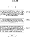
- the first lens group G1 having a positive refractive power, the second lens group G2 closer to an image than the first lens group G1 and having a negative refractive power, the third lens group G3 closer to an image than the second lens group G2 and having a positive refractive power, and the fourth lens group G4 closer to an image than the third lens group G3 and having a negative refractive power are arranged (Step ST11).
- a vibration proof group movable so as to have a displacement component in a direction perpendicular to an optical axis is provided on at least part of the second lens group G2.
- a positive lens and a negative lens are arranged in order from an object and an air distance is present between the positive lens and the negative lens (Step ST13).
- each lens is arranged within a lens barrel so as to satisfy at least the aforementioned conditional expression (13) and the conditional expression (14) (Step ST14).
- a telephoto type zoom optical system having a higher zooming rate is manufactured.
- a zoom optical system ZL (9) as an example of the zoom optical system (zoom lens) ZL according to the third embodiment comprises: as illustrated in FIG. 33 , a first lens group G1 having a positive refractive power, a second lens group G2 disposed closer to an image than the first lens group G1 and having a negative refractive power, a third lens group G3 disposed closer to an image than the second lens group G2 and having a positive refractive power, and a following group GR disposed closer to an image than the third lens group G3 and consisting of at least one lens group (fourth lens group G4 and fifth lens group G5).
- a distance between the first lens group G1 and the second lens group G2 changes, a distance between the second lens group G2 and the third lens group G3 changes, and a distance between the third lens group G3 and the following group GR changes during zooming.
- any one of the first lens group G1, the second lens group G2, the third lens group G3, and the following group GR is configured to include a vibration proof group movable so as to have a displacement component in a direction perpendicular to an optical axis.
- the vibration proof group consists of a positive lens, a first negative lens, and a second negative lens disposed in order from an object. It should be noted that an air distance is present between the positive lens and the first negative lens, and an air distance is present between the first negative lens and the second negative lens. Accordingly, a telephoto type zoom optical system having a small-sized vibration proof group is achieved.
- the zoom optical system ZL according to the third embodiment may be a zoom optical system ZL (10) illustrated in FIG. 37 ; may be a zoom optical system ZL (11) illustrated in FIG. 41 ; and may be a zoom optical system ZL (12) illustrated in FIG. 45 . It should be noted that groups from the zoom optical system ZL (10) to ZL (12) illustrated in FIG. 37 or other drawings are configured in the same manner as the zoom optical system ZL (9) illustrated in FIG. 33 .
- the second lens group G2 consists of the aforementioned vibration proof group. Accordingly, the eccentric coma aberration and the eccentric curvature of field when the shake compensation is performed may be successfully corrected. Also, the lateral chromatic aberration and the distortion in the wide angle end state may be successfully corrected.
- the following group GR includes a fourth lens group G4 disposed closer to an image than the third lens group G3, and at least part of lenses in the fourth lens group G4 moves along the optical axis during focusing. Accordingly, variations in chromatic aberration and variation in spherical aberration during focusing may be successfully corrected.
- the following group GR includes a fourth lens group G4 disposed closer to an image than the third lens group G3, and the following conditional expression (22) is satisfied. 0.40 ⁇ f 4 / ⁇ f 2 ⁇ 4.00 where,
- the conditional expression (22) is a conditional expression for defining an adequate range for a ratio of focal lengths between the fourth lens group G4 and the second lens group G2.
- a corresponding value of the conditional expression (22) exceeds an upper limit value, the power (refractive power) of the second lens group G2 is too much stronger than the power of the fourth lens group G4, which makes it difficult to correct spherical aberration and coma aberration in the telephoto end state.
- the upper limit value of the conditional expression (22) is preferably set to 3.30, and more preferably to 2.70.
- the lower limit value of the conditional expression (22) is preferably set to 0.60, and more preferably to 0.80.
- an aperture stop S is disposed between the second lens group G2 and the third lens group G3. Accordingly, the astigmatism, the coma aberration, and the lateral chromatic aberration may be successfully corrected.
- the third lens group G3 consists of the object side subgroup having a positive refractive power and the image side subgroup having a positive refractive power disposed in order from an object, and when a lens component including a negative lens is disposed at a position closest to the object in the image side subgroup, (in each example of the following description, the object side subgroup and the image side subgroup in such a case are referred to as first object side subgroup and first image side subgroup), the following conditional expression (23) is satisfied. 0.08 ⁇ f 3 ⁇ a / f 3 ⁇ b ⁇ 1.20 where,
- the conditional expression (23) is a conditional expression for defining an adequate range for a ratio of focal lengths between the object side subgroup and the image side subgroup in the third lens group G3.
- the lens component indicates a single lens or a cemented lens.
- the upper limit value of the conditional expression (23) is preferably set to 1.00, and more preferably to 0.80.
- the lower limit value of the conditional expression (23) is preferably set to 0.09, and more preferably to 0.10.
- the third lens group G3 consists of the object side subgroup having a positive refractive power and the image side subgroup having a positive refractive power disposed in order from an object, and when the air distance between the object side subgroup and the image side subgroup is the maximum air distance between the air distance between lenses in the third lens group G3, (in each example of the following description, the object side subgroup and the image side subgroup in such a case are referred to as second object side subgroup and second image side subgroup), the following conditional expression (24) is satisfied. 0.40 ⁇ f 3 ⁇ ⁇ / f 3 ⁇ ⁇ ⁇ 1.40 where,
- the conditional expression (24) is a conditional expression for defining an adequate range for a ratio of focal lengths between the object side subgroup and the image side subgroup in the third lens group G3.
- the upper limit value of the conditional expression (24) is preferably set to 1.15, and more preferably to 0.90.
- the lower limit value of the conditional expression (24) is preferably set to 0.05, and more preferably to 0.06.
- the following group GR includes a fourth lens group G4 disposed closer to an image than the third lens group G3, and the fourth lens group G4 includes a positive lens and a negative lens disposed in order from an object, and an air distance is present between the positive lens and the negative lens. Accordingly, variations in chromatic aberration and variation in spherical aberration during focusing may be successfully corrected.
- the following conditional expression (25) is satisfied. 0.40 ⁇ f 3 / ⁇ f 2 ⁇ 2.60 where,
- the conditional expression (25) is a conditional expression for defining an adequate range for a ratio of focal lengths between the third lens group G3 and the second lens group G2.
- a corresponding value of the conditional expression (25) exceeds an upper limit value, the power of the second lens group G2 is too much stronger than the power of the third lens group G3, which makes it difficult to correct the astigmatism in the wide angle end state.
- the upper limit value of the conditional expression (25) is preferably set to 2.20, and more preferably to 1.80.
- the lower limit value of the conditional expression (25) is preferably set to 0.55, and more preferably to 0.70.
- the following group GR includes a fourth lens group G4 disposed closer to an image than the third lens group G3, and the following conditional expression (26) is satisfied. 0.10 ⁇ f 3 / f 4 ⁇ 1.50 where,
- the conditional expression (26) is a conditional expression for defining an adequate range for a ratio of focal lengths between the third lens group G3 and the fourth lens group G4.
- a corresponding value of the conditional expression (26) exceeds an upper limit value, the power of the fourth lens group G4 is too much stronger than the power of the third lens group G3, which makes it difficult to correct the coma aberration in the wide angle end state.
- the upper limit value of the conditional expression (26) is preferably set to 1.25, and more preferably to 1.00.
- the lower limit value of the conditional expression (26) is preferably set to 0.20, and more preferably to 0.30.
- the following conditional expression (27) is satisfied. 0.30 ⁇ m 12 / fw ⁇ 2.30 where,
- the conditional expression (27) is a conditional expression for defining an adequate range for variable magnification burden of the second lens group G2.
- the upper limit value of the conditional expression (27) is preferably set to 1.90, and more preferably to 1.50.
- the lower limit value of the conditional expression (27) is preferably set to 0.50, and more preferably to 0.70.
- the following group GR includes a fourth lens group G4 disposed closer to an image than the third lens group G3, and the following conditional expression (28) is satisfied. 0.080 ⁇ m 34 / fw ⁇ 0.800 where,
- the conditional expression (28) is a conditional expression for achieving both the variable magnification burden and the aberration correction effect of the fourth lens group G4.
- the corresponding value of the conditional expression (28) exceeds the upper limit value, the amount of change (absolute value) in distance between the third lens group G3 and the fourth lens group G4 increases. Therefore, the variable magnification burden of the fourth lens group G4 increases, which makes it difficult to correct spherical aberration in the telephoto end state and astigmatism in the wide angle end state.
- the upper limit value of the conditional expression (28) is preferably set to 0.650, and more preferably to 0.500.
- the lower limit value of the conditional expression (28) undergoes the lower limit value, the amount of change (absolute value) in distance between the third lens group G3 and the fourth lens group G4 decreases, and thus the aberration correction effect of change in distance between the third lens group G3 and the fourth lens group G4 is less likely achieved. Therefore, achievement of both the aberration correction in the telephoto end state and the aberration correction in the wide angle end state is difficult, which makes it difficult to correct the spherical aberration and astigmatism in the wide angle end state.
- the lower limit value of the conditional expression (28) is preferably set to 0.130, and more preferably to 0.180.
- An optical apparatus is configured with the zoom optical system having a configuration described above.
- a camera (optical apparatus) provided with the zoom optical system ZL according to the third embodiment will be described with reference to FIG. 49 .
- the camera 1 is a digital camera provided with the zoom optical system according to the embodiment described above as an imaging lens 2 as illustrated in FIG. 49 .
- light from an object (subject) not illustrated is converged by the imaging lens 2, and reaches an image pickup device 3. Accordingly, light from the subject is imaged by the image pickup device 3, and is recorded in a memory, not illustrated, as a subject image.
- a photographer is allowed to photograph the subject by the camera 1 in this manner.
- the camera may be a mirror-less camera, or may be a single lens reflex type camera having a quick return mirror.
- the zoom optical system ZL according to the third embodiment as the imaging lens, a small-sized optical apparatus including a small-sized vibration proof group is achieved.
- the first lens group G1 having a positive refractive power, the second lens group G2 closer to an image than the first lens group G1 and having a negative refractive power, the third lens group G3 closer to an image than the second lens group G2 and having a positive refractive power, and the following group GR consisting of at least one lens group closer to an image than the third lens group G3 are disposed in a lens barrel (Step ST21).
- Step ST22 it is configured that a distance between the first lens group G1 and the second lens group G2 changes, a distance between the second lens group G2 and the third lens group G3 changes, and a distance between the third lens group G3 and the following group GR changes during zooming (Step ST22).
- any one of the first lens group G1, the second lens group G2, the third lens group G3, and the following group GR includes a vibration proof group movable so as to have a displacement component in a direction perpendicular to an optical axis
- the vibration proof group may consist of a positive lens, a first negative lens, and a second negative lens disposed in order from an object, and each lens is disposed within a lens barrel so that an air distance is present between the positive lens and the first negative lens and an air distance is present between the first negative lens and the second negative lens.
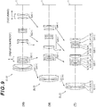
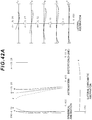
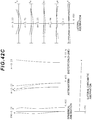
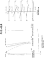
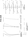
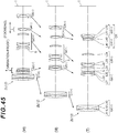
- FIG. 1 , FIG. 5 , FIG. 9 , FIG. 13 , FIG. 17 , FIG. 21 , FIG. 25 , FIG. 29 , FIG. 33 , FIG. 37 , FIG. 41 , and FIG. 45 are cross-sectional views illustrating configurations and distributions of refractive power of the zoom optical system ZL ⁇ ZL (1) to ZL (12) ⁇ according to Examples 1 to 12.
- Each cross-sectional view illustrate positions of the respective lens groups when zooming from the wide angle end state (W) via the intermediate focal length state (M) to the telephoto end state (T) is performed.
- Arrows in the middle parts of these drawings indicate directions of movement of the first to fourth lens groups G1 to G4 (or the fifth lens group G5) when zooming (zooming operation) from the wide angle end state through the intermediate focal length state to the telephoto end state is performed.
- a direction of movement of the fourth lens group G4 for focusing from an infinity to a short distant object as a zooming group is indicated by an arrow associated with a term "FOCUSING".
- a direction of movement of at least part of the second lens group G2 for correcting an image blur as a vibration proof group is indicated by an arrow associated with a term "VIBRATION PROOF".
- each lens group is indicated by a combination of a sign G and a number
- each lens is indicated by a combination of a sign L and a number.
- the lens groups are indicated by using combinations of the sign and the number independently from example to example. Therefore, even when the combination of the same sign and the number are used in examples, it does not mean that they have the same configuration.
- Tables 1 to 12 are shown below. Among these tables, Table 1 shows data of Example 1, Table 2 shows data of Example 2, Table 3 shows data of Example 3, Table 4 shows data of Example 4, Table 5 shows data of Example 5, Table 6 shows data of Example 6, Table 7 shows data of Example 7, Table 8 shows data of Example 8, Table 9 shows data of Example 9, Table 10 shows data of Example 10, Table 11 shows data of Example 11, and Table 12 shows data of Example 12.
- f represents a focal length of a whole lens system
- FNO represents F number
- 2 ⁇ represents the angle of view (unit is degree (°) and ⁇ is a half angle of view)
- Y represents the maximum image height.
- TL represents a distance obtained by adding BF to a distance from a lens forefront surface to a lens last surface on an optical axis upon focusing on infinity
- BF indicates an air equivalent distance (back focus) from the lens last surface to an image surface I on the optical axis upon focusing on infinity.
- ⁇ represents a maximum effective diameter of a lens surface on the object side in a positive lens component of the third lens group disposed so as to oppose the image side of the aperture stop
- ⁇ represents an absolute value of a difference between an aspherical amount at a position corresponding to the maximum effective diameter of the lens surface on the object side in the positive lens component and an aspherical amount at a position corresponding to the maximum effective diameter of the lens surface on the image side in the positive lens component.
- the surface numbers indicate the orders of the optical surfaces from the object side along the direction of the traveling of the rays
- the sign R indicates a radius of curvature of each optical surface (a positive value is allocated to the surface where the center of curvature is located on the image side)
- the sign D represents a distance to the next lens surface, which corresponds to the distance from each optical surface to the next optical surface (or an image surface) on the optical axis
- the sign nd indicates the refractive index of a material of the optical member for d-line
- the sign vd indicates an abbe number with reference to the d-line of the material of the optical member.
- the lens surface is an aspherical surface, the surface number is asterisked, and a paraxial radius of curvature is shown in a column of the radius of curvature R.
- X(y) represents a distance (sag amount) along the direction of the optical axis from a tangent surface at a vertex of the aspherical surface to a position on the aspherical surface at a height y
- R represents a radius of curvature (paraxial radius of curvature) of a reference spherical surface
- ⁇ represents a conical coefficient
- Ai represents an i th order aspherical coefficient.
- E-n represents " ⁇ 10 -n ".
- 1.234E - 05 1.234 ⁇ 10 -5 .
- the 2nd order aspherical coefficient A2 is 0, and notation of which is omitted.
- X y y 2 / R / 1 + 1 ⁇ ⁇ ⁇ y 2 / R 2 1 / 2 + A 4 ⁇ y 4 + A 6 ⁇ y 6 + A 8 ⁇ y 8 + A 10 ⁇ y 10
- the unit "mm" is generally used for the focal length f, the radius of curvature R, the distance to the next lens surface D, and other lengths in all data values.
- the optical system is not limited thereto because the optical system achieves an equivalent optical performance even when the optical system is proportionally enlarged or proportionally contracted.
- FIG. 1 is a drawing illustrating a lens configuration of a zoom optical system according to Example 1.
- the zoom optical system ZL (1) according to Example 1 consists of, in order from an object, a first lens group G1 having a positive refractive power, a second lens group G2 having a negative refractive power, an aperture stop S, a third lens group G3 having a positive refractive power, and a fourth lens group G4 having a negative refractive power.
- W wide angle end state
- T telephoto end state
- the first to fourth lens groups G1 to G4 move in the directions indicated by the arrows shown in FIG. 1 .
- the first lens group G1 corresponds to the object side lens group in the first embodiment.
- the second lens group G2 corresponds to the first negative lens group in the first embodiment.
- the third lens group G3 corresponds to the intermediate lens group in the first embodiment.
- the fourth lens group G4 corresponds to the second negative lens group in the first embodiment. Sign (+) or (-) accompanied with each lens group indicate the refractive power of each lens group, which applies to all other examples described below.
- the zoom optical system ZL (1) according to Example 1 focusing from the infinity to the short distant object is achieved by moving all the lenses in the fourth lens group G4 to the image side along the optical axis. Also, in the zoom optical system ZL (1) according to Example 1, the second negative lens L22 in the second lens group G2, the third negative lens L23, and the positive lens L24 constitute the vibration proof group movable in the direction perpendicular to the optical axis, and corrects a displacement of an imaging position due to camera shake or the like (image blur on the image surface I).
- the moving lens group for shake compensation may simply move in a direction perpendicular to the optical axis by (f ⁇ tan ⁇ )/K.
- the vibration proof coefficient is -1.16
- the focal length is 51.50 mm. Therefore, the amount of movement of the vibration-proof lens group for correcting the rotational blur of 0.38° is -0.29 mm.
- the vibration proof coefficient In the intermediate focal length state of Example 1, the vibration proof coefficient is -2.13, the focal length is 146.99 mm. Therefore, the amount of movement of the vibration-proof lens group for correcting the rotational blur of 0.30° is -0.36 mm. In the telephoto end state of Example 1, the vibration proof coefficient is -3.07, the focal length is 242.50 mm. Therefore, the amount of movement of the vibration-proof lens group for correcting the rotational blur of 0.30° is -0.41 mm.
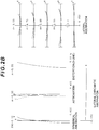
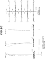
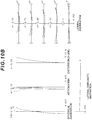
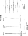
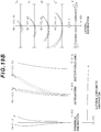
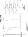
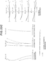
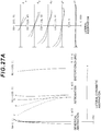
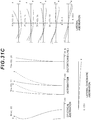
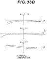
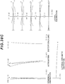
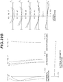
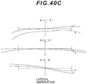
- FIG. 2A , FIG. 2B and FIG. 2C are each an aberration graph illustrating aberrations upon focusing on infinity in a wide angle end state, in an intermediate focal length state, and in a telephoto end state of the zoom optical system having a vibration proof function according to Example 1.
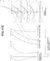
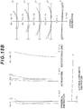
- FIG. 3A , FIG. 3B and FIG. 3C are each an aberration graph illustrating aberrations upon focusing on short distance (close range) in a wide angle end state, in an intermediate focal length state, and in a telephoto end state of the zoom optical system having a vibration proof function according to Example 1.
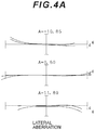
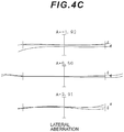
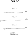
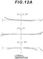
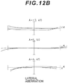
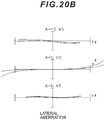
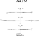
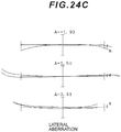
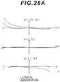
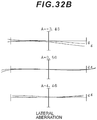
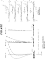
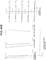
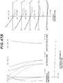
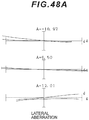
- FIG. 4A , FIG. 4B , and FIG. 4C are each a meridional lateral aberration graph when shake compensation is performed in the wide angle end state, in the intermediate focal length state, and in the telephoto end state of the zoom optical system having a vibration proof function according to Example 1.
- FNO indicates an F number
- A indicates a half angle of view.
- NA indicates a numerical aperture
- HO indicates the object height.
- the values of the numerical aperture corresponding to the maximum aperture are shown in the spherical aberration graphs, and the maximum values of the object height are shown respectively in the astigmatism graphs and in the distortion graphs, and the values of the respective object height are shown in the lateral aberration graphs.
- A indicates a half angle of view.
- the values of the half angle of view are shown.
- the zoom optical system according to Example 1 has an excellent image forming performance capable of correcting various aberrations successfully from the wide angle end state to the telephoto end state, and also has an excellent image forming performance also upon focusing on a short distant object.
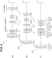
- FIG. 5 is a drawing illustrating a lens configuration of a zoom optical system according to Example 2.
- the zoom optical system ZL (2) according to Example 2 consists of, in order from an object, a first lens group G1 having a positive refractive power; a second lens group G2 having a negative refractive power; an aperture stop S; a third lens group G3 having a positive refractive power; and a fourth lens group G4 having a negative refractive power.
- W wide angle end state
- T telephoto end state
- the first to fourth lens groups G1 to G4 move in the directions indicated by the arrows shown in FIG. 5 .
- the first lens group G1 corresponds to the object side lens group in the first embodiment.
- the second lens group G2 corresponds to the first negative lens group in the first embodiment.
- the third lens group G3 corresponds to the intermediate lens group in the first embodiment.
- the fourth lens group G4 corresponds to the second negative lens group in the first embodiment.
- the first lens group G1, the second lens group G2 and the fourth lens group G4 have the same configuration as in Example 1, so that the same signs as those in Example 1 are allocated, and detailed descriptions of these lenses will be omitted.
- the third lens group G3 consists of, in order from an object, a meniscus shaped first positive lens L31 having a convex surface facing the object, the second positive lens L32 meniscus shaped facing a convex surface thereof to the object side, a cemented lens consisting of a meniscus shaped negative lens L33 having a convex surface facing the object and a third lens L34 having a biconvex shape, and a fourth positive lens L35 having a biconvex shape.
- the aperture stop S is provided near the object side of the third lens group G3, and moves integrally with the third lens group G3 during zooming.
- a lens surface on the object side of the first positive lens L31 has an aspherical surface, and is disposed on the image side of the aperture stop S so as to face the aperture stop S.
- the first positive lens L31 and the second positive lens L32 constitute the first object side subgroup
- the negative lens L33, the third lens L34, and the fourth positive lens L35 constitute the first image side subgroup.
- the first positive lens L31 and the second positive lens L32 constitute the second object side subgroup
- the negative lens L33, the third lens L34, and the fourth positive lens L35 constitute the second image side subgroup.
- the zoom optical system ZL (2) according to Example 2 focusing from the infinity to the short distant object is achieved by moving all the lenses in the fourth lens group G4 to the image side along the optical axis. Also, in the zoom optical system ZL (2) according to Example 2, the second negative lens L22 in the second lens group G2, the third negative lens L23, and the positive lens L24 constitute the vibration proof group movable in the direction perpendicular to the optical axis, and corrects a displacement of an imaging position due to camera shake or the like (image blur on the image surface I).
- the moving lens group for shake compensation may simply move in a direction perpendicular to the optical axis by (f ⁇ tan ⁇ )/K.
- the vibration proof coefficient is -1.21
- the focal length is 51.50 mm. Therefore, the amount of movement of the vibration-proof lens group for correcting the rotational blur of 0.38° is -0.28 mm.
- the vibration proof coefficient is -2.18, the focal length is 147.00 mm. Therefore, the amount of movement of the vibration-proof lens group for correcting the rotational blur of 0.30° is -0.35 mm.
- the vibration proof coefficient is -3.12, the focal length is 242.51 mm. Therefore, the amount of movement of the vibration-proof lens group for correcting the rotational blur of 0.30° is -0.41 mm.
- FIG. 6A , FIG. 6B and FIG. 6C are each an aberration graph illustrating aberrations upon focusing on infinity in a wide angle end state, in an intermediate focal length state, and in a telephoto end state of the zoom optical system having a vibration proof function according to Example 2.
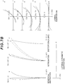
- FIG. 7A , FIG. 7B and FIG. 7C are each an aberration graph illustrating aberrations upon focusing on short distance (close range) in a wide angle end state, in an intermediate focal length state, and in a telephoto end state of the zoom optical system having a vibration proof function according to Example 2.
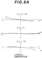
- Example 8C are each a meridional lateral aberration graph when shake compensation is performed in the wide angle end state, in the intermediate focal length state, and in the telephoto end state of the zoom optical system having a vibration proof function according to Example 2. It is apparent from respective aberration graphs that the zoom optical system according to Example 2 has an excellent image forming performance capable of correcting various aberrations successfully from the wide angle end state to the telephoto end state, and also has an excellent image forming performance also upon focusing on a short distant object.
- FIG. 9 is a drawing illustrating a lens configuration of a zoom optical system according to Example 3.
- the zoom optical system ZL (3) according to Example 3 consists of, in order from an object, a first lens group G1 having a positive refractive power, a second lens group G2 having a negative refractive power, an aperture stop S, a third lens group G3 having a positive refractive power, and a fourth lens group G4 having a negative refractive power.
- W wide angle end state
- T telephoto end state
- the first to fourth lens groups G1 to G4 move in the directions indicated by the arrows shown in FIG. 9 .
- the first lens group G1 corresponds to the object side lens group in the first embodiment.
- the second lens group G2 corresponds to the first negative lens group in the first embodiment.
- the third lens group G3 corresponds to the intermediate lens group in the first embodiment.
- the fourth lens group G4 corresponds to the second negative lens group in the first embodiment.
- the first lens group G1, the second lens group G2 and the fourth lens group G4 have the same configuration as in Example 1, so that the same signs as those in Example 1 are allocated, and detailed descriptions of these lenses will be omitted.
- the third lens group G3 consists of, in order from an object, a cemented lens consisting of a first positive lens L31 having a biconvex shape and a first negative lens L32 having a biconcave shape, a cemented lens consisting of a meniscus shaped second negative lens L33 having a convex surface facing the object, and a second positive lens L34 having a biconvex shape, and a third positive lens L35 having a biconvex shape.
- the aperture stop S is provided near the object side of the third lens group G3, and moves integrally with the third lens group G3 during zooming.
- a lens surface on the object side of the first positive lens L31 has an aspherical surface, and is disposed on the image side of the aperture stop S so as to face the aperture stop S.
- the first positive lens L31 and the first negative lens L32 constitute the first object side subgroup
- the second negative lens L33, the second positive lens L34, and the third positive lens L35 constitute the first image side subgroup.
- the first positive lens L31 and the first negative lens L32 constitute the second object side subgroup
- the second negative lens L33, the second positive lens L34, and the third positive lens L35 constitute the second image side subgroup.
- the zoom optical system ZL (3) according to Example 3 focusing from the infinity to the short distant object is achieved by moving all the lenses in the fourth lens group G4 to the image side along the optical axis. Also, in the zoom optical system ZL (3) according to Example 3, the second negative lens L22 in the second lens group G2, the third negative lens L23, and the positive lens L24 constitute the vibration proof group movable in the direction perpendicular to the optical axis, and corrects a displacement of an imaging position due to camera shake or the like (image blur on the image surface I).
- the moving lens group for shake compensation may simply move in a direction perpendicular to the optical axis by (f ⁇ tan ⁇ )/K.
- the vibration proof coefficient is -1.14
- the focal length is 51.49 mm. Therefore, the amount of movement of the vibration-proof lens group for correcting the rotational blur of 0.38° is -0.30 mm.
- the vibration proof coefficient is -2.09, the focal length is 146.98 mm. Therefore, the amount of movement of the vibration-proof lens group for correcting the rotational blur of 0.30° is -0.37 mm.
- the vibration proof coefficient is -3.01, the focal length is 242.46 mm. Therefore, the amount of movement of the vibration-proof lens group for correcting the rotational blur of 0.30° is -0.42 mm.
- FIG. 10A , FIG. 10B and FIG. 10C are each an aberration graph illustrating aberrations upon focusing on infinity in a wide angle end state, in an intermediate focal length state, and in a telephoto end state of the zoom optical system having a vibration proof function according to Example 3.
- FIG. 11A , FIG. 11B and FIG. 11C are each an aberration graph illustrating aberrations upon focusing on short distance (close range) in a wide angle end state, in an intermediate focal length state, and in a telephoto end state of the zoom optical system having a vibration proof function according to Example 3.
- the zoom optical system according to Example 3 has an excellent image forming performance capable of correcting various aberrations successfully from the wide angle end state to the telephoto end state, and also has an excellent image forming performance also upon focusing on a short distant object.
- FIG. 13 is a drawing illustrating a lens configuration of a zoom optical system according to Example 4.
- the zoom optical system ZL (4) according to Example 4 consists of, in order from an object, a first lens group G1 having a positive refractive power, a second lens group G2 having a negative refractive power, an aperture stop S, a third lens group G3 having a positive refractive power, and a fourth lens group G4 having a negative refractive power.
- W wide angle end state
- T telephoto end state
- the first to fourth lens groups G1 to G4 move in the directions indicated by the arrows shown in FIG. 13 .
- the first lens group G1 corresponds to the object side lens group in the first embodiment.
- the second lens group G2 corresponds to the first negative lens group in the first embodiment.
- the third lens group G3 corresponds to the intermediate lens group in the first embodiment.
- the fourth lens group G4 corresponds to the second negative lens group in the first embodiment.
- the first lens group G1 and the fourth lens group G4 have the same configuration as in the first embodiment, so that the same reference signs as those in Example 1 are allocated, and detailed descriptions of these lenses will be omitted.
- the second lens group G2 consists of, in order from an object, a meniscus shaped first negative lens L21 having a convex surface facing the object, the second negative lens L22 having a biconcave shape, and a meniscus shaped positive lens L23 having a convex surface facing the object.
- the first negative lens L21, the second negative lens L22, and the positive lens L23 constitute the vibration proof group.
- the third lens group G3 consists of, in order from an object, a meniscus shaped first positive lens L31 having a convex surface facing the object, a cemented lens consisting of a meniscus shaped negative lens L32 having a convex surface facing the object and a second positive lens L33 having a biconvex shape, and a third positive lens L34 having a biconvex shape.
- the aperture stop S is provided near the object side of the third lens group G3, and moves integrally with the third lens group G3 during zooming.
- a lens surface on the object side of the first positive lens L31 has an aspherical surface, and is disposed on the image side of the aperture stop S so as to face the aperture stop S.
- the first positive lens L31 constitutes the first object side subgroup
- the negative lens L32, the second positive lens L33, and the third positive lens L34 constitute the first image side subgroup.
- the first positive lens L31 constitutes the second object side subgroup
- the negative lens L32, the second positive lens L33, and the third positive lens L34 constitute the second image side subgroup.
- zoom optical system ZL (4) according to Example 4 focusing from the infinity to the short distant object is achieved by moving all the lenses in the fourth lens group G4 to the image side. Also, in the zoom optical system ZL (4) according to Example 4, all the lenses in the second lens group G2 constitute the vibration proof group movable in the direction perpendicular to the optical axis, and corrects a displacement of an imaging position due to camera shake or the like (image blur on the image surface I) .
- the moving lens group for shake compensation may simply move in a direction perpendicular to the optical axis by (f ⁇ tan ⁇ )/K.
- the vibration proof coefficient is -1.11
- the focal length is 51.50 mm. Therefore, the amount of movement of the vibration-proof lens group for correcting the rotational blur of 0.38° is -0.30 mm.
- the vibration proof coefficient is -2.06, the focal length is 146.99 mm. Therefore, the amount of movement of the vibration-proof lens group for correcting the rotational blur of 0.30° is -0.37 mm.
- the vibration proof coefficient is -3.00, the focal length is 242.48 mm. Therefore, the amount of movement of the vibration-proof lens group for correcting the rotational blur of 0.30° is -0.42 mm.
- FIG. 14A , FIG. 14B and FIG. 14C are each an aberration graph illustrating aberrations upon focusing on infinity in a wide angle end state, in an intermediate focal length state, and in a telephoto end state of the zoom optical system having a vibration proof function according to Example 4.
- FIG. 15A , FIG. 15B and FIG. 15C are each an aberration graph illustrating aberrations upon focusing on short distance (close range) in a wide angle end state, in an intermediate focal length state, and in a telephoto end state of the zoom optical system having a vibration proof function according to Example 4.
- 16C are each a meridional lateral aberration graph when shake compensation is performed in the wide angle end state, in the intermediate focal length state, and in the telephoto end state of the zoom optical system having a vibration proof function according to Example 4. It is apparent from respective aberration graphs that the zoom optical system according to Example 4 has an excellent image forming performance capable of correcting various aberrations successfully from the wide angle end state to the telephoto end state, and also has an excellent image forming performance also upon focusing on a short distant object.
- FIG. 17 is a drawing illustrating a lens configuration of a zoom optical system according to Example 5.
- the zoom optical system ZL (5) according to Example 5 consists of, in order from an object, a first lens group G1 having a positive refractive power, a second lens group G2 having a negative refractive power, an aperture stop S, a third lens group G3 having a positive refractive power, a fourth lens group G4 having a negative refractive power, and a fifth lens group G5 having a negative refractive power.
- the first lens group G1 corresponds to the object side lens group in the first embodiment.
- the second lens group G2 corresponds to the first negative lens group in the first embodiment.
- the third lens group G3 corresponds to the intermediate lens group in the first embodiment.
- the fourth lens group G4 corresponds to the second negative lens group in the first embodiment.
- the fifth lens group G5 corresponds to the image side lens group in the first embodiment.
- the zoom optical system ZL (5) according to Example 5 focusing from the infinity to the short distant object is achieved by moving all the lenses in the fourth lens group G4 to the image side along the optical axis. Also, in the zoom optical system ZL (5) according to Example 5, the second negative lens L22 in the second lens group G2, the third negative lens L23, and the positive lens L24 constitute the vibration proof group movable in the direction perpendicular to the optical axis, and corrects a displacement of an imaging position due to camera shake or the like (image blur on the image surface I).
- the moving lens group for shake compensation may simply move in a direction perpendicular to the optical axis by (f ⁇ tan ⁇ )/K.
- the vibration proof coefficient is -1.21
- the focal length is 51.50 mm. Therefore, the amount of movement of the vibration-proof lens group for correcting the rotational blur of 0.38° is -0.28 mm.
- the vibration proof coefficient is -2.14, the focal length is 146.99 mm. Therefore, the amount of movement of the vibration-proof lens group for correcting the rotational blur of 0.30° is -0.36 mm.
- the vibration proof coefficient is -3.08, the focal length is 242.48 mm. Therefore, the amount of movement of the vibration-proof lens group for correcting the rotational blur of 0.30° is -0.41 mm.
- FIG. 18A , FIG. 18B and FIG. 18C are each an aberration graph illustrating aberrations upon focusing on infinity in a wide angle end state, in an intermediate focal length state, and in a telephoto end state of the zoom optical system having a vibration proof function according to Example 5.
- FIG. 19A , FIG. 19B and FIG. 19C are each an aberration graph illustrating aberrations upon focusing on short distance (close range) in a wide angle end state, in an intermediate focal length state, and in a telephoto end state of the zoom optical system having a vibration proof function according to Example 5.
- the zoom optical system according to Example 5 has an excellent image forming performance capable of correcting various aberrations successfully from the wide angle end state to the telephoto end state, and also has an excellent image forming performance also upon focusing on a short distant object.
- FIG. 21 is a drawing illustrating a lens configuration of a zoom optical system according to Example 6.
- the zoom optical system ZL (6) according to Example 6 consists of, in order from an object, a first lens group G1 having a positive refractive power, a second lens group G2 having a negative refractive power, an aperture stop S, a third lens group G3 having a positive refractive power, a fourth lens group G4 having a negative refractive power, and a fifth lens group G5 having a positive refractive power.
- the first lens group G1 corresponds to the object side lens group in the first embodiment.
- the second lens group G2 corresponds to the first negative lens group in the first embodiment.
- the third lens group G3 corresponds to the intermediate lens group in the first embodiment.
- the fourth lens group G4 corresponds to the second negative lens group in the first embodiment.
- the fifth lens group G5 corresponds to the image side lens group in the first embodiment.
- zoom optical system ZL (6) according to Example 6 focusing from the infinity to the short distant object is achieved by moving all the lenses in the fourth lens group G4 to the image side along the optical axis. Also, in the zoom optical system ZL (6) according to Example 6, all the lenses in the second lens group G2 constitute the vibration proof group movable in the direction perpendicular to the optical axis, and corrects a displacement of an imaging position due to camera shake or the like (image blur on the image surface I).
- the moving lens group for shake compensation may simply move in a direction perpendicular to the optical axis by (f ⁇ tan ⁇ )/K.
- the vibration proof coefficient is -1.18
- the focal length is 51.50 mm. Therefore, the amount of movement of the vibration-proof lens group for correcting the rotational blur of 0.38° is -0.29 mm.
- the vibration proof coefficient is -2.12, the focal length is 147.00 mm. Therefore, the amount of movement of the vibration-proof lens group for correcting the rotational blur of 0.30° is -0.36 mm.
- the vibration proof coefficient is -3.02, the focal length is 242.50 mm. Therefore, the amount of movement of the vibration-proof lens group for correcting the rotational blur of 0.30° is -0.42 mm.
- FIG. 22A , FIG. 22B and FIG. 22C are each an aberration graph illustrating aberrations upon focusing on infinity in a wide angle end state, in an intermediate focal length state, and in a telephoto end state of the zoom optical system having a vibration proof function according to Example 6.
- FIG. 23A , FIG. 23B and FIG. 23C are each an aberration graph illustrating aberrations upon focusing on short distance (close range) in a wide angle end state, in an intermediate focal length state, and in a telephoto end state of the zoom optical system having a vibration proof function according to Example 6.
- the zoom optical system according to Example 6 has an excellent image forming performance capable of correcting various aberrations successfully from the wide angle end state to the telephoto end state, and also has an excellent image forming performance also upon focusing on a short distant object.
- FIG. 25 is a drawing illustrating a lens configuration of a zoom optical system according to Example 7.
- the zoom optical system ZL (7) according to Example 7 consists of, in order from an object, a first lens group G1 having a positive refractive power, a second lens group G2 having a negative refractive power, an aperture stop S, a third lens group G3 having a positive refractive power, a fourth lens group G4 having a negative refractive power, and a fifth lens group G5 having a positive refractive power.
- the first lens group G1 corresponds to the object side lens group in the first embodiment.
- the second lens group G2 corresponds to the first negative lens group in the first embodiment.
- the third lens group G3 corresponds to the intermediate lens group in the first embodiment.
- the fourth lens group G4 corresponds to the second negative lens group in the first embodiment.
- the fifth lens group G5 corresponds to the image side lens group in the first embodiment.
- zoom optical system ZL (7) according to Example 7 focusing from the infinity to the short distant object is achieved by moving all the lenses in the fourth lens group G4 to the image side along the optical axis. Also, in the zoom optical system ZL (7) according to Example 7, all the lenses in the second lens group G2 constitute the vibration proof group movable in the direction perpendicular to the optical axis, and corrects a displacement of an imaging position due to camera shake or the like (image blur on the image surface I).
- the moving lens group for shake compensation may simply move in a direction perpendicular to the optical axis by (f ⁇ tan ⁇ )/K.
- the vibration proof coefficient is -1.04
- the focal length is 51.50 mm. Therefore, the amount of movement of the vibration-proof lens group for correcting the rotational blur of 0.38° is -0.33 mm.
- the vibration proof coefficient is -1.92, the focal length is 146.99 mm. Therefore, the amount of movement of the vibration-proof lens group for correcting the rotational blur of 0.30° is -0.40 mm.
- the vibration proof coefficient is -2.87, the focal length is 242.46 mm. Therefore, the amount of movement of the vibration-proof lens group for correcting the rotational blur of 0.30° is -0.44 mm.
- FIG. 26A , FIG. 26B and FIG. 26C are each an aberration graph illustrating aberrations upon focusing on infinity in a wide angle end state, in an intermediate focal length state, and in a telephoto end state of the zoom optical system having a vibration proof function according to Example 7.
- FIG. 27A , FIG. 27B and FIG. 27C are each an aberration graph illustrating aberrations upon focusing on short distance (close range) in a wide angle end state, in an intermediate focal length state, and in a telephoto end state of the zoom optical system having a vibration proof function according to Example 7.
- the zoom optical system according to Example 7 has an excellent image forming performance capable of correcting various aberrations successfully from the wide angle end state to the telephoto end state, and also has an excellent image forming performance also upon focusing on a short distant object.
- FIG. 29 is a drawing illustrating a lens configuration of a zoom optical system according to Example 8.
- the zoom optical system ZL (8) according to Example 8 consists of, in order from an object, a first lens group G1 having a positive refractive power, a second lens group G2 having a negative refractive power, an aperture stop S, a third lens group G3 having a positive refractive power, a fourth lens group G4 having a negative refractive power, and a fifth lens group G5 having a positive refractive power.
- the first lens group G1 corresponds to the object side lens group in the first embodiment.
- the second lens group G2 corresponds to the first negative lens group in the first embodiment.
- the third lens group G3 corresponds to the intermediate lens group in the first embodiment.
- the fourth lens group G4 corresponds to the second negative lens group in the first embodiment.
- the fifth lens group G5 corresponds to the image side lens group in the first embodiment.
- zoom optical system ZL (8) according to Example 8 focusing from the infinity to the short distant object is achieved by moving all the lenses in the fourth lens group G4 to the image side along the optical axis. Also, in the zoom optical system ZL (8) according to Example 8, all the lenses in the second lens group G2 constitute the vibration proof group movable in the direction perpendicular to the optical axis, and corrects a displacement of an imaging position due to camera shake or the like (image blur on the image surface I).
- the moving lens group for shake compensation may simply move in a direction perpendicular to the optical axis by (f ⁇ tan ⁇ )/K.
- the vibration proof coefficient is -1.02
- the focal length is 51.50 mm. Therefore, the amount of movement of the vibration-proof lens group for correcting the rotational blur of 0.38° is -0.33 mm.
- the vibration proof coefficient is -1.86, the focal length is 147.00 mm. Therefore, the amount of movement of the vibration-proof lens group for correcting the rotational blur of 0.30° is -0.41 mm.
- the vibration proof coefficient is -2.68, the focal length is 242.50 mm. Therefore, the amount of movement of the vibration-proof lens group for correcting the rotational blur of 0.30° is -0.47 mm.
- FIG. 30A , FIG. 30B and FIG. 30C are each an aberration graph illustrating aberrations upon focusing on infinity in a wide angle end state, in an intermediate focal length state, and in a telephoto end state of the zoom optical system having a vibration proof function according to Example 8.
- FIG. 31A , FIG. 31B and FIG. 31C are each an aberration graph illustrating aberrations upon focusing on short distance (close range) in a wide angle end state, in an intermediate focal length state, and in a telephoto end state of the zoom optical system having a vibration proof function according to Example 8.
- 32C are each a meridional lateral aberration graph when shake compensation is performed in the wide angle end state, in the intermediate focal length state, and in the telephoto end state of the zoom optical system having a vibration proof function according to Example 8. It is apparent from respective aberration graphs that the zoom optical system according to Example 8 has an excellent image forming performance capable of correcting various aberrations successfully from the wide angle end state to the telephoto end state, and also has an excellent image forming performance also upon focusing on a short distant object.
- FIG. 33 is a drawing illustrating a lens configuration of a zoom optical system according to Example 9.
- the zoom optical system ZL (9) according to Example 9 consists of, in order from an object, a first lens group G1 having a positive refractive power; a second lens group G2 having a negative refractive power; an aperture stop S; a third lens group G3 having a positive refractive power; a fourth lens group G4 having a negative refractive power, and a fifth lens group G5 having a negative refractive power.
- the first to fifth lens groups G1 to G5 move in the directions indicated by the arrows shown in FIG. 33 .
- the third lens group G3 and the fifth lens group G5 move synchronously.
- the first lens group G1 corresponds to the object side lens group in the first embodiment.
- the second lens group G2 corresponds to the first negative lens group in the first embodiment.
- the third lens group G3 corresponds to the intermediate lens group in the first embodiment.
- the fourth lens group G4 corresponds to the second negative lens group in the first embodiment.
- the fifth lens group G5 corresponds to the image side lens group in the first embodiment.
- the fourth lens group G4 and the fifth lens group G5 constitute the following group GR in the third embodiment.
- zoom optical system ZL (9) according to Example 9 focusing from the infinity to the short distant object is achieved by moving all the lenses in the fourth lens group G4 to the image side along the optical axis. Also, in the zoom optical system ZL (9) according to Example 9, all the lenses in the second lens group G2 constitute the vibration proof group movable in the direction perpendicular to the optical axis, and corrects a displacement of an imaging position due to camera shake or the like (image blur on the image surface I).
- the moving lens group for shake compensation may simply move in a direction perpendicular to the optical axis by (f ⁇ tan ⁇ )/K.
- the vibration proof coefficient is -1.14
- the focal length is 51.25 mm. Therefore, the amount of movement of the vibration-proof lens group for correcting the rotational blur of 0.38° is -0.29 mm.
- the vibration proof coefficient is -2.14, the focal length is 150.00 mm. Therefore, the amount of movement of the vibration-proof lens group for correcting the rotational blur of 0.30° is -0.37 mm. In the telephoto end state of Example 9, the vibration proof coefficient is -3.00, the focal length is 243.75 mm. Therefore, the amount of movement of the vibration-proof lens group for correcting the rotational blur of 0.30° is -0.42 mm.
- FIG. 34A , FIG. 34B and FIG. 34C are each an aberration graph illustrating aberrations upon focusing on infinity in a wide angle end state, in an intermediate focal length state, and in a telephoto end state of the zoom optical system having a vibration proof function according to Example 9.
- FIG. 35A , FIG. 35B and FIG. 35C are each an aberration graph illustrating aberrations upon focusing on short distance (close range) in a wide angle end state, in an intermediate focal length state, and in a telephoto end state of the zoom optical system having a vibration proof function according to Example 9.
- 36C are each a meridional lateral aberration graph when shake compensation is performed in the wide angle end state, in the intermediate focal length state, and in the telephoto end state of the zoom optical system having a vibration proof function according to Example 9. It is apparent from respective aberration graphs that the zoom optical system according to Example 9 has an excellent image forming performance capable of correcting various aberrations successfully from the wide angle end state to the telephoto end state, and also has an excellent image forming performance also upon focusing on a short distant object.
- FIG. 37 is a drawing illustrating a lens configuration of a zoom optical system according to Example 10.
- the zoom optical system ZL (10) according to Example 10 consists of, in order from an object, a first lens group G1 having a positive refractive power, a second lens group G2 having a negative refractive power, an aperture stop S, a third lens group G3 having a positive refractive power, a fourth lens group G4 having a negative refractive power, and a fifth lens group G5 having a negative refractive power.
- the first to fifth lens groups G1 to G5 move in the directions indicated by the arrows shown in FIG. 37 .
- the third lens group G3 and the fifth lens group G5 move synchronously.
- the first lens group G1 corresponds to the object side lens group in the first embodiment.
- the second lens group G2 corresponds to the first negative lens group in the first embodiment.
- the third lens group G3 corresponds to the intermediate lens group in the first embodiment.
- the fourth lens group G4 corresponds to the second negative lens group in the first embodiment.
- the fifth lens group G5 corresponds to the image side lens group in the first embodiment.
- the fourth lens group G4 and the fifth lens group G5 constitute the following group GR in the third embodiment.
- zoom optical system ZL (10) according to Example 10 focusing from the infinity to the short distant object is achieved by moving all the lenses in the fourth lens group G4 to the image side along the optical axis. Also, in the zoom optical system ZL (10) according to Example 10, all the lenses in the second lens group G2 constitute the vibration proof group movable in the direction perpendicular to the optical axis, and corrects a displacement of an imaging position due to camera shake or the like (image blur on the image surface I).
- the moving lens group for shake compensation may simply move in a direction perpendicular to the optical axis by (f ⁇ tan ⁇ )/K.
- the vibration proof coefficient is -1.15
- the focal length is 51.25 mm. Therefore, the amount of movement of the vibration-proof lens group for correcting the rotational blur of 0.38° is -0.29 mm.
- the vibration proof coefficient In the intermediate focal length state of Example 10, the vibration proof coefficient is -2.17, the focal length is 150.00 mm. Therefore, the amount of movement of the vibration-proof lens group for correcting the rotational blur of 0.30° is -0.36 mm. In the telephoto end state of Example 10, the vibration proof coefficient is -3.00, the focal length is 243.75 mm. Therefore, the amount of movement of the vibration-proof lens group for correcting the rotational blur of 0.30° is -0.42 mm.
- FIG. 38A , FIG. 38B and FIG. 38C are each an aberration graph illustrating aberrations upon focusing on infinity in a wide angle end state, in an intermediate focal length state, and in a telephoto end state of the zoom optical system having a vibration proof function according to Example 10.
- FIG. 39A , FIG. 39B and FIG. 39C are each an aberration graph illustrating aberrations upon focusing on short distance (close range) in a wide angle end state, in an intermediate focal length state, and in a telephoto end state of the zoom optical system having a vibration proof function according to Example 10.
- the zoom optical system according to Example 10 has an excellent image forming performance capable of correcting various aberrations successfully from the wide angle end state to the telephoto end state, and also has an excellent image forming performance also upon focusing on a short distant object.
- FIG. 41 is a drawing illustrating a lens configuration of a zoom optical system according to Example 11.
- the zoom optical system ZL (11) according to Example 11 consists of, in order from an object, a first lens group G1 having a positive refractive power, a second lens group G2 having a negative refractive power, an aperture stop S, a third lens group G3 having a positive refractive power, a fourth lens group G4 having a negative refractive power, and a fifth lens group G5 having a positive refractive power.
- the first to fifth lens groups G1 to G5 move in the directions indicated by the arrows shown in FIG. 41 .
- the third lens group G3 and the fifth lens group G5 move synchronously.
- the first lens group G1 corresponds to the object side lens group in the first embodiment.
- the second lens group G2 corresponds to the first negative lens group in the first embodiment.
- the third lens group G3 corresponds to the intermediate lens group in the first embodiment.
- the fourth lens group G4 corresponds to the second negative lens group in the first embodiment.
- the fifth lens group G5 corresponds to the image side lens group in the first embodiment.
- the fourth lens group G4 and the fifth lens group G5 constitute the following group GR in the third embodiment.
- zoom optical system ZL (11) according to Example 11 focusing from the infinity to the short distant object is achieved by moving all the lenses in the fourth lens group G4 to the image side along the optical axis. Also, in the zoom optical system ZL (11) according to Example 11, all the lenses in the second lens group G2 constitute the vibration proof group movable in the direction perpendicular to the optical axis, and corrects a displacement of an imaging position due to camera shake or the like (image blur on the image surface I).
- the moving lens group for shake compensation may simply move in a direction perpendicular to the optical axis by (f ⁇ tan ⁇ )/K.
- the vibration proof coefficient is -1.13
- the focal length is 51.25 mm. Therefore, the amount of movement of the vibration-proof lens group for correcting the rotational blur of 0.38° is -0.30 mm.
- the vibration proof coefficient is -2.10, the focal length is 150.00 mm. Therefore, the amount of movement of the vibration-proof lens group for correcting the rotational blur of 0.30° is -0.37 mm. In the telephoto end state of Example 11, the vibration proof coefficient is -3.00, the focal length is 243.75 mm. Therefore, the amount of movement of the vibration-proof lens group for correcting the rotational blur of 0.30° is -0.42 mm.
- FIG. 42A , FIG. 42B and FIG. 42C are each an aberration graph illustrating aberrations upon focusing on infinity in a wide angle end state, in an intermediate focal length state, and in a telephoto end state of the zoom optical system having a vibration proof function according to Example 11.
- FIG. 43A , FIG. 43B and FIG. 43C are each an aberration graph illustrating aberrations upon focusing on short distance (close range) in a wide angle end state, in an intermediate focal length state, and in a telephoto end state of the zoom optical system having a vibration proof function according to Example 11.
- Example 44C are each a meridional lateral aberration graph when shake compensation is performed in the wide angle end state, in the intermediate focal length state, and in the telephoto end state of the zoom optical system having a vibration proof function according to Example 11. It is apparent from respective aberration graphs that the zoom optical system according to Example 11 has an excellent image forming performance capable of correcting various aberrations successfully from the wide angle end state to the telephoto end state, and also has an excellent image forming performance also upon focusing on a short distant object.
- FIG. 45 is a drawing illustrating a lens configuration of a zoom optical system according to Example 12.
- the zoom optical system ZL (12) according to Example 12 consists of, in order from an object, a first lens group G1 having a positive refractive power, a second lens group G2 having a negative refractive power, an aperture stop S, a third lens group G3 having a positive refractive power, a fourth lens group G4 having a positive refractive power, and a fifth lens group G5 having a negative refractive power.
- the first to fifth lens groups G1 to G5 move in the directions indicated by the arrows shown in FIG. 45 .
- the third lens group G3 and the fifth lens group G5 move synchronously.
- the fourth lens group G4 and the fifth lens group G5 constitute the following group GR in the third embodiment.
- zoom optical system ZL (12) according to Example 12 focusing from the infinity to the short distant object is achieved by moving all the lenses in the fourth lens group G4 to the image side along the optical axis. Also, in the zoom optical system ZL (12) according to Example 12, all the lenses in the second lens group G2 constitute the vibration proof group movable in the direction perpendicular to the optical axis, and corrects a displacement of an imaging position due to camera shake or the like (image blur on the image surface I).
- the moving lens group for shake compensation may simply move in a direction perpendicular to the optical axis by (f ⁇ tan ⁇ )/K.
- the vibration proof coefficient is -1.04
- the focal length is 51.25 mm. Therefore, the amount of movement of the vibration-proof lens group for correcting the rotational blur of 0.38° is -0.32 mm.
- the vibration proof coefficient is -2.19, the focal length is 150.00 mm. Therefore, the amount of movement of the vibration-proof lens group for correcting the rotational blur of 0.30° is -0.36 mm. In the telephoto end state of Example 12, the vibration proof coefficient is -3.00, the focal length is 243.75 mm. Therefore, the amount of movement of the vibration-proof lens group for correcting the rotational blur of 0.30° is -0.42 mm.
- FIG. 46A , FIG. 46B and FIG. 46C are each an aberration graph illustrating aberrations upon focusing on infinity in a wide angle end state, in an intermediate focal length state, and in a telephoto end state of the zoom optical system having a vibration proof function according to Example 12.
- FIG. 47A , FIG. 47B and FIG. 47C are each an aberration graph illustrating aberrations upon focusing on short distance (close range) in a wide angle end state, in an intermediate focal length state, and in a telephoto end state of the zoom optical system having a vibration proof function according to Example 12.
- Example 48C are each a meridional lateral aberration graph when shake compensation is performed in the wide angle end state, in the intermediate focal length state, and in the telephoto end state of the zoom optical system having a vibration proof function according to Example 12. It is apparent from respective aberration graphs that the zoom optical system according to Example 12 has an excellent image forming performance capable of correcting various aberrations successfully from the wide angle end state to the telephoto end state, and also has an excellent image forming performance also upon focusing on a short distant object.
- Examples 1 to 11 the optical performance in the wide angle end state is improved, and thus a telephoto type zoom optical system having a wider angle of view is achieved. According to Examples 1 to 11, a telephoto type zoom optical system having a higher zooming rate is achieved. According to the Examples 9 to 12, a telephoto type zoom optical system having a small-sized vibration proof group is achieved.
- each example described above shows a specific example of each embodiment, and the embodiments are not limited thereto.
- zoom optical systems with other number of groups for example, 6 groups
- a configuration in which two or more lens groups having positive or negative refractive power disposed closer to an image than the second negative lens group is also applicable.
- the lens group means a portion having at least one lens separated at an air distance that varies during zooming of the lens group.
- the focusing lens group may be configured to focus from an infinite distant object to a short distant object by moving a single or a plurality of lens groups or a partial lens group in the optical axis direction instead of the at least part of lenses in the second negative lens group.
- the focusing lens group may be applied to autofocusing, and is also suitable to the motor driving for autofocusing (using a stepping motor or the like).
- the amount of change of the image surface at the time of focusing during imaging a movie may be suppressed by reducing an image surface movement coefficient by specifying the focal length of the second negative lens group to an adequate range.
- the lens surface may be formed of a spherical surface or a flat surface, or even of an aspherical surface.
- aberration correction by using an aspherical surface for a positive lens component arranged so as to oppose the image side of the aperture stop enables reduction of the number of lenses of the lens group including the aperture stop (or the lens group disposed so as to oppose the image side of the aperture stop in the case where the aperture stop moves solely during zooming).
- adjustment of aberration correction and manufacture sensitivity is enabled by using the aspherical surface for the positive lens component disposed so as to oppose the image side of the aperture stop and also by using an air distance in the lens group including the aperture stop (or the lens group disposed so as to oppose the image side of the aperture stop in the case where the aperture stop moves solely during zooming).
- the lens surface is a spherical surface or a flat surface, machining and assembly adjustment are easy. It is therefore preferable because deterioration of optical performance due to errors in machining and assembly adjustment is prevented. In addition, it is preferable because deterioration of descriptive performance is not much even when the image surface is displaced.
- the aspherical surface may be any of an aspherical surface formed by grinding, a glass mold aspherical surface formed of glass into an aspherical shape by a mold, and a composite type aspherical surface fabricated by forming a resin into an aspherical surface shape on a surface of glass.
- the lens surface may be a diffraction surface, and the lenses may be gradient index lenses (GRIN lenses) or plastic lenses.
- the aperture stop is preferably disposed between the second lens group and the third lens group, but may be disposed in the third lens group or on the image side of the third lens group. Alternatively, a member as the aperture stop may not be provided and a lens frame may be used instead to perform the role of the aperture stop.
- Each lens surface may be coated with an antireflection film having a high transmittance in a wide wavelength region for reducing flare and ghost and achieving a high contrast optical performance. Accordingly, the flare and the ghost may be reduced, and a high optical performance with a high contrast is achieved.
Landscapes
- Physics & Mathematics (AREA)
- General Physics & Mathematics (AREA)
- Optics & Photonics (AREA)
- Nonlinear Science (AREA)
- Lenses (AREA)
- Adjustment Of Camera Lenses (AREA)
- Camera Bodies And Camera Details Or Accessories (AREA)
Abstract

where,
fGa : a focal length of the first negative lens group (G2), and
fGb : a focal length of the second negative lens group (G4).
Description
- The present invention relates to a zoom optical system, optical apparatus using the zoom optical system, and a method for manufacturing the zoom optical system.
- Conventionally, a zoom optical system equipped with a vibration proof group for correcting image blur has been proposed (see, for example, Patent Literature 1). However, in a zoom optical system equipped with a vibration proof group, a wider angle of view is required. Also, in a zoom optical system equipped with a vibration proof group, a higher zooming rate is required. Also, in a zoom optical system equipped with a vibration proof group, achieving a small size of the vibration proof group is required.
- Patent literature 1: Japanese Laid-Open Patent Publication No.
11-316342(A - A zoom optical system according to a first aspect comprises: a first negative lens group having a negative refractive power; and a second negative lens group disposed closer to an image than the first negative lens group, and a distance between the first negative lens group and the second negative lens group changes during zooming, and the first negative lens group is movable so that at least a part thereof has a displacement component in a direction perpendicular to the optical axis. At least a part of the second negative lens group is movable along the optical axis during focusing. These lens groups satisfy the following conditional expressions,

- fGa : a focal length of the first negative lens group and,
- fGb : a focal length of the second negative lens group.
- A zoom optical system according to a second aspect comprises: a first lens group having a positive refractive power, a second lens group disposed closer to an image than the first lens group and having a negative refractive power, a third lens group disposed closer to an image than the second lens group and having a positive refractive power, and a fourth lens group disposed closer to an image than the third lens group and having a negative refractive power, and a distance between the first lens group and the second lens group changes, a distance between the second lens group and the third lens group changes, a distance between the third lens group and the fourth lens group changes during zooming, the second lens group includes at least partly a vibration proof group movable so as to have a displacement component in a direction perpendicular to an optical axis, the fourth lens group includes a positive lens and a negative lens disposed in order from an object, an air distance is present between the positive lens and the negative lens, and the following conditional expressions,


where - Dpn : an air distance between the positive lens and the negative lens in the fourth lens group,
- f4 : a focal length of the fourth lens group,
- fVR : a focal length of the vibration proof group, and
- f2 : a focal length of the second lens group.
- A zoom optical system according to a third aspect comprises: a first lens group having a positive refractive power, a second lens group disposed closer to an image than the first lens group and having a negative refractive power, a third lens group disposed closer to an image than the second lens group and having a positive refractive power, and a following group (or succeeding group) disposed closer to an image than the third lens group and consisting of at least one lens group, and a distance between the first lens group and the second lens group changes, a distance between the second lens group and the third lens group changes, a distance between the third lens group and the following group changes during zooming, any one of the first lens group, the second lens group, the third lens group, and the following group includes at least partly a vibration proof group movable so as to have a displacement component in a direction perpendicular to an optical axis, the vibration proof group consists of a positive lens, a first negative lens, and a second negative lens disposed in order from an object, an air distance is present between the positive lens and the first negative lens, and an air distance is present between the first negative lens and the second negative lens.
- An optical apparatus according to a fourth aspect includes the zoom optical system mounted thereon.
- A method for manufacturing a zoom optical system according to a fifth aspect is a method of manufacturing a zoom optical system comprising: a first negative lens group having a negative refractive power; and a second negative lens group disposed closer to an image than the first negative lens group, and a distance between the first negative lens group and the second negative lens group changes during zooming, the first negative lens group is movable at least partly so as to have a displacement component in a direction perpendicular to an optical axis, at least part of the second negative lens group is movable along the optical axis during focusing, and each lens is disposed within a lens barrel so as to satisfy the following conditional expression,

- fGa : a focal length of the first negative lens group and,
- fGb : a focal length of the second negative lens group.
- A method for manufacturing a zoom optical system according to a sixth aspect is a method of manufacturing a zoom optical system comprising: a first lens group having a positive refractive power, a second lens group disposed closer to an image than the first lens group and having a negative refractive power, a third lens group disposed closer to an image than the second lens group and having a positive refractive power, and a fourth lens group disposed closer to an image than the third lens group and having a negative refractive power, and a distance between the first lens group and the second lens group changes, a distance between the second lens group and the third lens group changes, a distance between the third lens group and the fourth lens group changes during zooming, the second lens group includes at least partly a vibration proof group movable so as to have a displacement component in a direction perpendicular to an optical axis, the fourth lens group includes a positive lens and a negative lens disposed in order from an object, an air distance is present between the positive lens and the negative lens, and each lens is disposed within a lens barrel so as to satisfy the following conditional expressions,


- Dpn : an air distance between the positive lens and the negative lens in the fourth lens group,
- f4 : a focal length of the fourth lens group,
- fVR : a focal length of the vibration proof group, and
- f2 : a focal length of the second lens group.
- A method for manufacturing a zoom optical system according to a seventh aspect is a method of manufacturing a zoom optical system comprising: a first lens group having a positive refractive power, a second lens group disposed closer to an image than the first lens group and having a negative refractive power, a third lens group disposed closer to an image than the second lens group and having a positive refractive power, and a following group disposed closer to an image than the third lens group and consisting of at least one lens group, and a distance between the first lens group and the second lens group changes, a distance between the second lens group and the third lens group changes, a distance between the third lens group and the following group changes during zooming, any one of the first lens group, the second lens group, the third lens group, and the following group includes at least partly a vibration proof group movable so as to have a displacement component in a direction perpendicular to an optical axis, the vibration proof group consists of a positive lens, a first negative lens, and a second negative lens disposed in order from an object, and each lens is disposed within a lens barrel so that an air distance is present between the positive lens and the first negative lens and an air distance is present between the first negative lens and the second negative lens.
-
-
FIG. 1 is a drawing illustrating a lens configuration of a zoom optical system according to Example 1; -
FIG. 2A ,FIG. 2B andFIG. 2C are each an aberration graph illustrating aberrations upon focusing on infinity in a wide angle end state, in an intermediate focal length state, and in a telephoto end state of the zoom optical system according to Example 1; -
FIG. 3A ,FIG. 3B , andFIG. 3C are each an aberration graph illustrating aberrations upon focusing on a short distant object in the wide angle end state, in the intermediate focal length state, and in the telephoto end state of the zoom optical system according to Example 1; -
FIG. 4A ,FIG. 4B , andFIG. 4C are each a meridional lateral (or transverse) aberration graph when shake compensation is performed in the wide angle end state, in the intermediate focal length state, and in the telephoto end state of the zoom optical system according to Example 1; -
FIG. 5 is a drawing illustrating a lens configuration of a zoom optical system according to Example 2; -
FIG. 6A ,FIG. 6B andFIG. 6C are each an aberration graph illustrating aberrations upon focusing on infinity in a wide angle end state, in an intermediate focal length state, and in a telephoto end state of the zoom optical system according to Example 2; -
FIG. 7A ,FIG. 7B , andFIG. 7C are each an aberration graph illustrating aberrations upon focusing on a short distant object in a wide angle end state, in an intermediate focal length state, and in a telephoto end state of the zoom optical system according to Example 2; -
FIG. 8A ,FIG. 8B , andFIG. 8C are each a meridional lateral aberration graph when shake compensation is performed in the wide angle end state, in the intermediate focal length state, and in the telephoto end state of the zoom optical system according to Example 2; -
FIG. 9 is a drawing illustrating a lens configuration of a zoom optical system according to Example 3; -
FIG. 10A ,FIG. 10B , andFIG. 10C are each an aberration graph illustrating aberrations upon focusing on infinity in a wide angle end state, in an intermediate focal length state, and in a telephoto end state of the zoom optical system according to Example 3; -
FIG. 11A ,FIG. 11B andFIG. 11C are each an aberration graph illustrating aberrations upon focusing on a short distant object in a wide angle end state, in an intermediate focal length state, and in a telephoto end state of the zoom optical system according to Example 3; -
FIG. 12A ,FIG. 12B , andFIG. 12C are each a meridional lateral aberration graph when shake compensation is performed in the wide angle end state, in the intermediate focal length state, and in the telephoto end state of the zoom optical system according to Example 3; -
FIG. 13 is a drawing illustrating a lens configuration of a zoom optical system according to Example 4; -
FIG. 14A ,FIG. 14B , andFIG. 14C are each an aberration graph illustrating aberrations upon focusing on infinity in a wide angle end state, in an intermediate focal length state, and in a telephoto end state of the zoom optical system according to Example 4; -
FIG. 15A ,FIG. 15B , andFIG. 15C are each an aberration graph illustrating aberrations upon focusing on a short distant object in a wide angle end state, in an intermediate focal length state, and in a telephoto end state of the zoom optical system according to Example 4; -
FIG. 16A ,FIG. 16B , andFIG. 16C are each a meridional lateral aberration graph when shake compensation is performed in the wide angle end state, in the intermediate focal length state, and in the telephoto end state of the zoom optical system according to Example 4; -
FIG. 17 is a drawing illustrating a lens configuration of a zoom optical system according to Example 5; -
FIG. 18A ,FIG. 18B , andFIG. 18C are each an aberration graph illustrating aberrations upon focusing on infinity in a wide angle end state, in an intermediate focal length state, and in a telephoto end state of the zoom optical system according to Example 5; -
FIG. 19A ,FIG. 19B , andFIG. 19C are each an aberration graph illustrating aberrations upon focusing on a short distant object in a wide angle end state, in an intermediate focal length state, and in a telephoto end state of the zoom optical system according to Example 5; -
FIG. 20A ,FIG. 20B , andFIG. 20C are each a meridional lateral aberration graph when shake compensation is performed in the wide angle end state, in the intermediate focal length state, and in the telephoto end state of the zoom optical system according to Example 5; -
FIG. 21 is a drawing illustrating a lens configuration of a zoom optical system according to Example 6; -
FIG. 22A ,FIG. 22B , andFIG. 22C are each an aberration graph illustrating aberrations upon focusing on infinity in a wide angle end state, in an intermediate focal length state, and in a telephoto end state of the zoom optical system according to Example 6; -
FIG. 23A ,FIG. 23B , andFIG. 23C are each an aberration graph illustrating aberrations upon focusing on a short distant object in a wide angle end state, in an intermediate focal length state, and in a telephoto end state of the zoom optical system according to Example 6; -
FIG. 24A ,FIG. 24B , andFIG. 24C are each a meridional lateral aberration graph when shake compensation is performed in the wide angle end state, in the intermediate focal length state, and in the telephoto end state of the zoom optical system according to Example 6; -
FIG. 25 is a drawing illustrating a lens configuration of a zoom optical system according to Example 7; -
FIG. 26A ,FIG. 26B , andFIG. 26C are each an aberration graph illustrating aberrations upon focusing on infinity in a wide angle end state, in an intermediate focal length state, and in a telephoto end state of the zoom optical system according to Example 7; -
FIG. 27A ,FIG. 27B , andFIG. 27C are each an aberration graph illustrating aberrations upon focusing on a short distant object in a wide angle end state, in an intermediate focal length state, and in a telephoto end state of the zoom optical system according to Example 7; -
FIG. 28A ,FIG. 28B , andFIG. 28C are each a meridional lateral aberration graph when shake compensation is performed in the wide angle end state, in the intermediate focal length state, and in the telephoto end state of the zoom optical system according to Example 7; -
FIG. 29 is a drawing illustrating a lens configuration of a zoom optical system according to an Example 8; -
FIG. 30A ,FIG. 30B , andFIG. 30C are each an aberration graph illustrating aberrations upon focusing on infinity in a wide angle end state, in an intermediate focal length state, and in a telephoto end state of the zoom optical system according to Example 8; -
FIG. 31A ,FIG. 31B , andFIG. 31C are each an aberration graph illustrating aberrations upon focusing on a short distant object in a wide angle end state, in an intermediate focal length state, and in a telephoto end state of the zoom optical system according to Example 8; -
FIG. 32A ,FIG. 32B , andFIG. 32C are each a meridional lateral aberration graph when shake compensation is performed in the wide angle end state, in the intermediate focal length state, and in the telephoto end state of the zoom optical system according to Example 8; -
FIG. 33 is a drawing illustrating a lens configuration of a zoom optical system according to Example 9; -
FIG. 34A ,FIG. 34B , andFIG. 34C are each an aberration graph illustrating aberrations upon focusing on infinity in a wide angle end state, in an intermediate focal length state, and in a telephoto end state of the zoom optical system according to Example 9; -
FIG. 35A ,FIG. 35B , andFIG. 35C are each an aberration graph illustrating aberrations upon focusing on a short distant object in a wide angle end state, in an intermediate focal length state, and in a telephoto end state of the zoom optical system according to Example 9; -
FIG. 36A ,FIG. 36B , andFIG. 36C are each a meridional lateral aberration graph when shake compensation is performed in the wide angle end state, in the intermediate focal length state, and in the telephoto end state of the zoom optical system according to Example 9; -
FIG. 37 is a drawing illustrating a lens configuration of a zoom optical system according to Example 10; -
FIG. 38A ,FIG. 38B , andFIG. 38C are each an aberration graph illustrating aberrations upon focusing on infinity in a wide angle end state, in an intermediate focal length state, and in a telephoto end state of the zoom optical system according to Example 10; -
FIG. 39A ,FIG. 39B , andFIG. 39C are each an aberration graph illustrating aberrations upon focusing on a short distant object in a wide angle end state, in an intermediate focal length state, and in a telephoto end state of the zoom optical system according to Example 10; -
FIG. 40A ,FIG. 40B , andFIG. 40C are each a meridional lateral aberration graph when shake compensation is performed in the wide angle end state, in the intermediate focal length state, and in the telephoto end state of the zoom optical system according to Example 10; -
FIG. 41 is a drawing illustrating a lens configuration of a zoom optical system according to an Example 11; -
FIG. 42A ,FIG. 42B , andFIG. 42C are each an aberration graph illustrating aberrations upon focusing on infinity in a wide angle end state, in an intermediate focal length state, and in a telephoto end state of the zoom optical system according to Example 11; -
FIG. 43A ,FIG. 43B , andFIG. 43C are each an aberration graph illustrating aberrations upon focusing on a short distant object in a wide angle end state, in an intermediate focal length state, and in a telephoto end state of the zoom optical system according to Example 11; -
FIG. 44A ,FIG. 44B , andFIG. 44C are each a meridional lateral aberration graph when shake compensation is performed in the wide angle end state, in the intermediate focal length state, and in the telephoto end state of the zoom optical system according to Example 11; -
FIG. 45 is a drawing illustrating a lens configuration of a zoom optical system according to Example 12; -
FIG. 46A ,FIG. 46B , andFIG. 46C are each an aberration graph illustrating aberrations upon focusing on infinity in a wide angle end state, in an intermediate focal length state, and in a telephoto end state of the zoom optical system according to Example 12; -
FIG. 47A ,FIG. 47B , andFIG. 47C are each an aberration graph illustrating aberrations upon focusing on a short distant object in a wide angle end state, in an intermediate focal length state, and in a telephoto end state of the zoom optical system according to Example 12; -
FIG. 48A ,FIG. 48B , andFIG. 48C are each a meridional lateral aberration graph when shake compensation is performed in the wide angle end state, in the intermediate focal length state, and in the telephoto end state of the zoom optical system according to Example 12; -
FIG. 49 is a drawing illustrating a configuration of a camera provided with the zoom optical system according to each embodiment; -
FIG. 50 is a flowchart illustrating a method for manufacturing a zoom optical system according to a first embodiment; -
FIG. 51 is a flowchart illustrating a method for manufacturing a zoom optical system according to a second embodiment; and -
FIG. 52 is a flowchart illustrating a method for manufacturing a zoom optical system according to a third embodiment. - A zoom optical system and an optical apparatus according to the first embodiment will now be described with reference to the drawings. A zoom optical system ZL (1) as an example of the zoom optical system (zoom lens) ZL according to the first embodiment includes: as illustrated in
FIG. 1 , a first negative lens group (second lens group G2) having a negative refractive power, and a second negative lens group (fourth lens group G4) disposed closer to an image than the first negative lens group. During zooming, a distance between the first negative lens group and the second negative lens group changes. At least part of the first negative lens group is movable so as to have a displacement component in a direction perpendicular to an optical axis. At least part of the second negative lens group is movable along the optical axis during focusing. - The zoom optical system ZL according to the first embodiment may be a zoom optical system ZL (2) illustrated in
FIG. 5 , may be a zoom optical system ZL (3) illustrated inFIG. 9 ; may be a zoom optical system ZL (4) illustrated inFIG. 13 ; may be a zoom optical system ZL (5) illustrated inFIG. 17 ; and may be a zoom optical system ZL (6) illustrated inFIG. 21 . The zoom optical system ZL of the first embodiment may be a zoom optical system ZL (7) illustrated inFIG. 25 ; may be a zoom optical system ZL (8) illustrated inFIG. 29 ; may be a zoom optical system ZL (9) illustrated inFIG. 33 ; may be a zoom optical system ZL (10) illustrated inFIG. 37 ; and may be a zoom optical system ZL (11) illustrated inFIG. 41 . It should be noted that groups from the zoom optical system ZL (2) to ZL (11) illustrated inFIG. 5 or other drawings are configured in the same manner as the zoom optical system ZL (1) illustrated inFIG. 1 . - The zoom optical system ZL according to the first embodiment having the configuration described above satisfies the following conditional expression. Accordingly, an optical performance in a wide angle end state is improved, and thus a telephoto type zoom optical system having a wider angle of view is achieved. In addition, by adjusting the power of the second negative lens group while balancing the powers of the first negative lens group and the second negative lens group, a zoom optical system suitable for imaging a video is achieved.

- fGa : a focal length of the first negative lens group, and
- fGb : a focal length of the second negative lens group.
- The conditional expression (1) is a conditional expression for defining an adequate range for a ratio of focal lengths between the second negative lens group (fourth lens group G4) and the first negative lens group (second lens group G2). When a corresponding value of the conditional expression (1) exceeds an upper limit value, the power (refractive power) of the first negative lens group is too much stronger than the power of the second negative lens group, which makes it difficult to correct spherical aberration and coma aberration in the telephoto end state. In order to ensure the effect of this embodiment, the upper limit value of the conditional expression (1) is preferably set to 2.40, and more preferably to 2.10.
- When the corresponding value of the conditional expression (1) undergoes a lower limit value, the power of the second negative lens group is too much stronger than the power of the first negative lens group, which makes it difficult to correct astigmatism in the wide angle end state and spherical aberration in the telephoto end state. In order to ensure the effect of this embodiment, the lower limit value of the conditional expression (1) is preferably set to 0.60, and more preferably to 0.70.
- In the zoom optical system ZL according to the first embodiment, the first negative lens group (second lens group G2) preferably includes at least partly a vibration proof group movable so as to have a displacement component in a direction perpendicular to an optical axis, and satisfies the following conditional expression (2).

fVR : a focal length of the vibration proof group. - The conditional expression (2) is a conditional expression for defining an adequate range for a ratio of focal lengths between the vibration proof group and the first negative lens group (second lens group G2). By satisfying the conditional expression (2), correction of the eccentric coma aberration and the eccentric curvature of field when the shake compensation is performed may be successfully corrected. Also, the lateral chromatic aberration and the distortion in the wide angle end state may be successfully corrected. In addition, the power of the first negative lens group is secured without increasing the power of the vibration proof group too much so that a zooming rate may be gained. For example, a zooming rate of three times or more, preferably, a zooming rate of four times of more may be achieved.
- When a corresponding value of the conditional expression (2) exceeds an upper limit value, the power of the first negative lens group is too much stronger than the power of the vibration proof group, which makes it difficult to correct lateral chromatic aberration and distortion in the wide angle end state. In order to ensure the effect of this embodiment, the upper limit value of the conditional expression (2) is preferably set to 2.10, and more preferably to 1.70.
- When the corresponding value of the conditional expression (2) undergoes the lower limit value, the power of the vibration proof group is too much stronger than the power of the first negative lens group, which makes it difficult to correct the eccentric coma aberration and the eccentric curvature of field when shake compensation is performed. In order to ensure the effect of this embodiment, the lower limit value of the conditional expression (2) is preferably set to 1.00.
- In the zoom optical system ZL according to the first embodiment, the second negative lens group (fourth lens group G4) preferably comprises a positive lens and a negative lens which are disposed in order from an object, and an air distance is present between the positive lens and the negative lens, and satisfies the following conditional expression (3).

Dpn : an air distance between the positive lens and the negative lens in the second negative lens group. - The conditional expression (3) is a conditional expression for defining an adequate range for an air distance between the positive lens and the negative lens in the second negative lens group (fourth lens group G4). By satisfying the conditional expression (3), a successful aberration correction is achieved. In addition, since manufacture sensitivity of the second negative lens group is lowered, the zoom optical system ZL is easily manufactured.
- When the corresponding value of the conditional expression (3) exceeds the upper limit value, the air distance between the positive lens and the negative lens in the second negative lens group increases, which makes it difficult to correct the astigmatism in the wide angle end state. In order to ensure the effect of this embodiment, the upper limit value of the conditional expression (3) is preferably set to 0.300, and more preferably to 0.200.
- When the corresponding value of the conditional expression (3) undergoes the lower limit value, the air distance between the positive lens and the negative lens in the second negative lens group decreases, which makes it difficult to correct the coma aberration in the telephoto end state. In order to ensure the effect of this embodiment, the lower limit value of the conditional expression (3) is preferably set to 0.003, and more preferably to 0.005.
- In the zoom optical system ZL according to the first embodiment, the first negative lens group (second lens group G2) may include at least partly a vibration proof group movable so as to have a displacement component in a direction perpendicular to an optical axis, the vibration proof group may consist of a positive lens, a first negative lens, and a second negative lens disposed in order from an object, an air distance may be present between the positive lens and the first negative lens, and an air distance may be present between the first negative lens and the second negative lens. Accordingly, the eccentric coma aberration and the eccentric curvature of field when the shake compensation is performed may be successfully corrected. Also, the lateral chromatic aberration and the distortion in the wide angle end state may be successfully corrected. Also, in the vibration proof group, a positive lens is disposed on an object side with respect to the first negative lens and the second negative lens, and thus reduction in diameter of the vibration proof group is enabled.
- Preferably, the zoom optical system ZL according to the first embodiment includes: an intermediate lens group (third lens group G3) disposed between the first negative lens group (second lens group G2) and the second negative lens group (fourth lens group G4), and the distance between the first negative lens group and the intermediate lens group changes, and the distance between the intermediate lens group and the second negative lens group changes during zooming. Accordingly, the distance between the first negative lens group and the intermediate lens group changes, and the distance between the intermediate lens group and the second negative lens group changes during zooming, and thus a high zooming rate is obtained.
- Preferably, the zoom optical system ZL according to the first embodiment includes: an object side lens group (first lens group G1) disposed on the object side with respect to the first negative lens group (second lens group G2) and having a positive refractive power, and the distance between the object side lens group and the first negative lens group changes during zooming. Accordingly, the distance between the object side lens group and the first negative lens group changes during zooming, and thus a high zooming rate is achieved.
- Preferably, the zoom optical system ZL according to the first embodiment includes: an image side lens group (fifth lens group G5) disposed closer to an image than the second negative lens group (fourth lens group G4), and the distance between the second negative lens group and the image side lens group changes during zooming. Accordingly, the distance between the second negative lens group and the image side lens group changes during zooming, and thus a high zooming rate is achieved.
- Preferably, the zoom optical system ZL according to the first embodiment includes: an intermediate lens group (third lens group G3) disposed between the first negative lens group (second lens group G2) and the second negative lens group (fourth lens group G4), and the distance between the first negative lens group and the intermediate lens group changes, and the distance between the intermediate lens group and the second negative lens group changes during zooming, and an aperture stop S is disposed between the first negative lens group and the intermediate lens group. Accordingly, the astigmatism, the coma aberration, and the lateral chromatic aberration may be successfully corrected.
- Preferably, the zoom optical system ZL according to the first embodiment includes: an intermediate lens group (third lens group G3) disposed between the first negative lens group (second lens group G2) and the second negative lens group (fourth lens group G4), and the distance between the first negative lens group and the intermediate lens group changes, and the distance between the intermediate lens group and the second negative lens group changes during zooming, and the intermediate lens group consists of the object side subgroup having a positive refractive power and the image side subgroup having a positive refractive power disposed in order from an object, and when a lens component including a negative lens is disposed at a position closest to the object in the image side subgroup (in each example of the following description, the object side subgroup and the image side subgroup in such a case are referred to as first object side subgroup and first image side subgroup), the following conditional expression (4) is satisfied.

- fa :
- a focal length of object side subgroup, and
- fb :
- a focal length of image side subgroup.
- The conditional expression (4) is a conditional expression for defining an adequate range for a ratio of focal lengths between the object side subgroup and the image side subgroup of the intermediate lens group (third lens group G3). By satisfying the conditional expression (4), the axial chromatic aberration and the spherical aberration are successfully corrected. It should be noted that, in each embodiment, the lens component indicates a single lens or a cemented lens.
- When the corresponding value of the conditional expression (4) exceeds the upper limit value, the power of the image side subgroup is too much stronger than the power of the object side subgroup, which makes it difficult to correct the axial chromatic aberration. In order to ensure the effect of this embodiment, the upper limit value of the conditional expression (4) is preferably set to 1.00, and more preferably to 0.80.
- When the corresponding value of the conditional expression (4) undergoes the lower limit value, the power of the object side subgroup is too much stronger than the power of the image side subgroup, which makes it difficult to correct the spherical aberration. In order to ensure the effect of this embodiment, the lower limit value of the conditional expression (4) is preferably set to 0.08, and more preferably to 0.10.
- Preferably, the zoom optical system ZL according to the first embodiment includes: an intermediate lens group (third lens group G3) disposed between the first negative lens group (second lens group G2) and the second negative lens group (fourth lens group G4), and the distance between the first negative lens group and the intermediate lens group changes, and the distance between the intermediate lens group and the second negative lens group changes during zooming, and the intermediate lens group consists of the object side subgroup having a positive refractive power and the image side subgroup having a positive refractive power disposed in order from an object, and when the air distance between the object side subgroup and the image side subgroup is the maximum air distance between the air distance between lenses in the intermediate lens group, (in each example of the following description, the object side subgroup and the image side subgroup in such a case are referred to as second object side subgroup and second image side subgroup), the following conditional expression (5) is satisfied.

- fα :
- a focal length of object side subgroup, and
- fβ :
- a focal length of image side subgroup.
- The conditional expression (5) is a conditional expression for defining an adequate range for a ratio of focal lengths between the object side subgroup and the image side subgroup of the intermediate lens group (third lens group G3). By satisfying the conditional expression (5), the axial chromatic aberration and the spherical aberration are successfully corrected.
- When the corresponding value of the conditional expression (5) exceeds the upper limit value, the power of the image side subgroup is too much stronger than the power of the object side subgroup, which makes it difficult to correct the axial chromatic aberration. In order to ensure the effect of this embodiment, the upper limit value of the conditional expression (5) is preferably set to 2.20, and more preferably to 1.80.
- When the corresponding value of the conditional expression (5) undergoes the lower limit value, the power of the object side subgroup is too much stronger than the power of the image side subgroup, which makes it difficult to correct the spherical aberration. In order to ensure the effect of this embodiment, the lower limit value of the conditional expression (5) is preferably set to 0.08, and more preferably to 0.10.
- In the zoom optical system ZL according to the first embodiment, the first negative lens group (second lens group G2) may include partly a vibration proof group movable so as to have a displacement component in a direction perpendicular to an optical axis, the first negative lens group may consist of a negative subgroup having a negative refractive power and the vibration proof group described above and having a negative refractive power disposed in order from an object, and a lens component including a positive lens may be disposed at a position closest to the image in the vibration proof group. Accordingly, the eccentric coma aberration and the eccentric curvature of field when the shake compensation is performed may be successfully corrected. Also, the lateral chromatic aberration and the distortion in the wide angle end state may be successfully corrected.
- Preferably, the zoom optical system ZL according to the first embodiment includes: an intermediate lens group (third lens group G3) disposed between the first negative lens group (second lens group G2) and the second negative lens group (fourth lens group G4), and the distance between the first negative lens group and the intermediate lens group changes, and the distance between the intermediate lens group and the second negative lens group changes during zooming, and the following conditional expression (6) is satisfied.

- fGc :
- a focal length of an intermediate lens group.
- The conditional expression (6) is a conditional expression for defining an adequate range for a ratio of focal lengths between the intermediate lens group (third lens group G3) and the first negative lens group (second lens group G2). When a corresponding value of the conditional expression (6) exceeds an upper limit value, the power of the first negative lens group is too much stronger than the power of the intermediate lens group, which makes it difficult to correct the astigmatism in the wide angle end state. In order to ensure the effect of this embodiment, the upper limit value of the conditional expression (6) is preferably set to 2.20, and more preferably to 1.80.
- When a corresponding value of the conditional expression (6) undergoes a lower limit value, the power of the intermediate lens group is too much stronger than the power of the first negative lens group, which makes it difficult to correct the astigmatism in the telephoto end state. In order to ensure the effect of this embodiment, the lower limit value of the conditional expression (6) is preferably set to 0.55, and more preferably to 0.70.
- Preferably, the zoom optical system ZL according to the first embodiment includes: an intermediate lens group (third lens group G3) disposed between the first negative lens group (second lens group G2) and the second negative lens group (fourth lens group G4), and the distance between the first negative lens group and the intermediate lens group changes, and the distance between the intermediate lens group and the second negative lens group changes during zooming, and the following conditional expression (7) is satisfied.

- fGc :
- a focal length of an intermediate lens group.
- The conditional expression (7) is a conditional expression for defining an adequate range for a ratio of focal lengths between the intermediate lens group (third lens group G3) and the second negative lens group (fourth lens group G4). When a corresponding value of the conditional expression (7) exceeds an upper limit value, the power of the second negative lens group is too much stronger than the power of the intermediate lens group, which makes it difficult to correct the coma aberration in the wide angle end state. In order to ensure the effect of this embodiment, the upper limit value of the conditional expression (7) is preferably set to 2.00, and more preferably to 1.60.
- When a corresponding value of the conditional expression (7) undergoes a lower limit value, the power of the intermediate lens group is too much stronger than the power of the second negative lens group, which makes it difficult to correct the astigmatism in the telephoto end state. In order to ensure the effect of this embodiment, the lower limit value of the conditional expression (7) is preferably set to 0.30, and more preferably to 0.40.
- Preferably, the zoom optical system ZL according to the first embodiment includes: an object side lens group (first lens group G1) disposed on the object side with respect to the first negative lens group (second lens group G2) and having a positive refractive power, and the distance between the object side lens group and the first negative lens group changes during zooming, and the following conditional expression (8) is satisfied.

- |mda| : an absolute value of the amount of change in distance from a lens surface closest to an image in the object side lens group to a lens surface closest to an object in the first negative lens group on the optical axis during zooming from the wide angle end state to the telephoto end state, and
- fw : a focal length of the zoom optical system ZL in the wide angle end state.
- The conditional expression (8) is a conditional expression for defining an adequate range for variable magnification burden of the first negative lens group (second lens group G2). When the corresponding value of the conditional expression (8) exceeds the upper limit value, the amount of change (absolute value) in distance between the object side lens group (first lens group G1) and the first negative lens group (second lens group G2) increases. Therefore, the variable magnification burden of the first negative lens group increases, which makes it difficult to correct the coma aberration and the curvature of field. In order to ensure the effect of this embodiment, the upper limit value of the conditional expression (8) is preferably set to 1.90, and more preferably to 1.50.
- When the corresponding value of the conditional expression (8) undergoes the lower limit value, the amount of change (absolute value) in distance between the object side lens group and the first negative lens group is too small to secure a high zooming rate. In order to secure a zooming rate in a state in which the corresponding value of the conditional expression (8) undergoes the lower limit value, the power of the first negative lens group needs to be stronger, which makes it difficult to correct the spherical aberration and the coma aberration. In order to ensure the effect of this embodiment, the lower limit value of the conditional expression (8) is preferably set to 0.40, and more preferably to 0.50.
- Preferably, the zoom optical system ZL according to the first embodiment includes: an intermediate lens group (third lens group G3) disposed between the first negative lens group (second lens group G2) and the second negative lens group (fourth lens group G4), and the distance between the first negative lens group and the intermediate lens group changes, and the distance between the intermediate lens group and the second negative lens group changes during zooming, and the following conditional expression (9) is satisfied.

- |mcb| : an absolute value of the amount of change in distance from a lens surface closest to an image in the intermediate lens group to a lens surface closest to an object in the second negative lens group on the optical axis during zooming from the wide angle end state to the telephoto end state, and
- fw : a focal length of the zoom optical system ZL in the wide angle end state.
- The conditional expression (9) is a conditional expression for achieving both the variable magnification burden and the aberration correction effect of the second negative lens group (fourth lens group G4). When the corresponding value of the conditional expression (9) exceeds the upper limit value, the amount of change (absolute value) in distance between the intermediate lens group (third lens group G3) and the second negative lens group (fourth lens group G4) increases. Therefore, the variable magnification burden of the second negative lens group increases, which makes it difficult to correct spherical aberration in the telephoto end state and astigmatism in the wide angle end state. In order to ensure the effect of this embodiment, the upper limit value of the conditional expression (9) is preferably set to 0.650, and more preferably to 0.550.
- When the lower limit value of the corresponding value of the conditional expression (9) undergoes the lower limit value, the amount of change (absolute value) in distance between the intermediate lens group and the second negative lens group decreases, and thus the aberration correction effect of change in distance between the intermediate lens group and the second negative lens group is less likely achieved. Therefore, achievement of both the aberration correction in the telephoto end state and the aberration correction in the wide angle end state is difficult, which makes it difficult to correct the spherical aberration and astigmatism in the wide angle end state. In order to ensure the effect of this embodiment, the lower limit value of the conditional expression (9) is preferably set to 0.065, and more preferably to 0.080.
- Preferably, the zoom optical system ZL according to the first embodiment includes: an aperture stop S disposed between the first negative lens group (second lens group G2) and the second negative lens group (fourth lens group G4), and a lens group (third lens group G3) having a positive lens component disposed so as to oppose the image side of the aperture stop S, and a distance between the first negative lens group and a lens group having a positive lens component changes, a distance between the lens group having the positive lens component and the second negative lens group changes during zooming, and the following conditional expression (10) is satisfied.

- fp : a focal length of the positive lens component, and
- fGp : a focal length of the lens group having the positive lens component.
- The conditional expression (10) is a conditional expression defining an adequate range of a focal length of the positive lens component disposed so as to oppose the image side of the aperture stop S. When the corresponding value of the conditional expression (10) exceeds the upper limit value, the power of the positive lens component decreases, which makes it difficult to correct the spherical aberration and the coma aberration. In order to ensure the effect of this embodiment, the upper limit value of the conditional expression (10) is preferably set to 3.00, and more preferably to 2.60.
- When the corresponding value of the conditional expression (10) undergoes the lower limit value, the power of the positive lens component increases, and thus, which is advantageous for correction of various aberrations such as spherical aberration as a representative example. However, it is not preferable because deterioration of optical performance becomes prominent when the positive lens component is deviated due to assembly accuracy at the time of manufacture. In order to ensure the effect of this embodiment, the lower limit value of the conditional expression (10) is preferably set to 0.50, and more preferably to 0.60.
- Preferably, the zoom optical system ZL according to the first embodiment includes: an aperture stop S disposed between the first negative lens group (second lens group G2) and the second negative lens group (fourth lens group G4), and a lens group (third lens group G3) having a positive lens component disposed so as to oppose the image side of the aperture stop S, and a distance between the first negative lens group and a lens group having a positive lens component changes, a distance between the lens group having the positive lens component and the second negative lens group changes during zooming, and the following conditional expression (11) is satisfied.

- LS : a sum of air distances on the image side of the positive lens component in the lens group having the positive lens component, and
- LGp : a thickness of the lens group having the positive lens component on the optical axis.
- The conditional expression (11) is a conditional expression defining an adequate range of the thickness of the lens group having the positive lens component on the optical axis. When the corresponding value of the conditional expression (11) exceeds the upper limit value, the power of the lens surface closer to an image than the positive lens component becomes stronger in the lens group having the positive lens component, which makes it difficult to correct the coma aberration in the telephoto end state and the astigmatism in the wide angle end state. In order to ensure the effect of this embodiment, the upper limit value of the conditional expression (11) is preferably set to 0.80, and more preferably to 0.70.
- When the corresponding value of the conditional expression (11) undergoes the lower limit value, the power of the lens surface closer to an image than the positive lens component becomes weaker in the lens group having the positive lens component, which makes it difficult to correct the coma aberration in the telephoto end state and the astigmatism in the wide angle end state. In order to ensure the effect of this embodiment, the lower limit value of the conditional expression (11) is preferably set to 0.42, and more preferably to 0.435.
- Preferably, the zoom optical system ZL according to the first embodiment includes: an aperture stop S disposed between the first negative lens group (second lens group G2) and the second negative lens group (fourth lens group G4), and a lens group (third lens group G3) having a positive lens component disposed so as to oppose the image side of the aperture stop S, and a distance between the first negative lens group and a lens group having a positive lens component changes, a distance between the lens group having the positive lens component and the second negative lens group changes during zooming, and at least one lens surface of the positive lens component has an aspherical surface, and the following conditional expression (12) is satisfied.

- ϕ : a maximum effective diameter of the lens surface on the object side of the positive lens component, and
- Δ : an absolute value between a difference between the aspherical amount at a position corresponding to the maximum effective diameter of the lens surface on the object side in the positive lens component and the aspherical amount at a position corresponding to the maximum effective diameter of the lens surface on the image side in the positive lens component.
- The conditional expression (12) is a conditional expression defining an adequate range of an aspherical amount (sag amount) of the positive lens component disposed so as to oppose the image side of the aperture stop S. It should be noted that the effective diameter of the lens surface on the object side in the positive lens component or the effective diameter of the lens surface on the image side becomes the maximum effective diameter upon focusing on infinity in the telephoto end state. However, the invention is not limited thereto. Also, the aspherical surface may be formed only on the lens surface on the object side of the positive lens component, may be formed only on the lens surface on the image side of the positive lens component, or may be formed on lens surfaces on both sides of the positive lens component. In other words, as described above, the aspherical surface needs only be formed on at least one of the lens surfaces of the positive lens component.
- When the corresponding value of the conditional expression (12) exceeds the upper limit value, the aspherical amount of the positive lens component increases, and thus, which is advantageous for correction of various aberrations such as spherical aberration as a representative example. However, it is not preferable because deterioration of optical performance becomes prominent when the positive lens component is deviated due to assembly accuracy at the time of manufacture. In order to ensure the effect of this embodiment, the upper limit value of the conditional expression (12) is preferably set to 1.00, and more preferably to 0.80.
- When the corresponding value of the conditional expression (12) undergoes the lower limit value, the aspherical amount of the positive lens component decreases, which makes it difficult to correct the spherical aberration and the coma aberration. In order to ensure the effect of this embodiment, the lower limit value of the conditional expression (12) is preferably set to 0.20, and more preferably to 0.25.
- An optical apparatus according to the first embodiment is configured with the zoom optical system having a configuration described above. As a specific example, a camera (optical apparatus) provided with the zoom optical system ZL according to the first embodiment will be described with reference to
FIG. 49 . Thecamera 1 is a digital camera provided with the zoom optical system according to the embodiment described above as animaging lens 2 as illustrated inFIG. 49 . In thiscamera 1, light from an object (subject) not illustrated is converged by theimaging lens 2, and reaches animage pickup device 3. Accordingly, light from the subject is imaged by theimage pickup device 3, and is recorded in a memory, not illustrated, as a subject image. A photographer is allowed to photograph the subject by thecamera 1 in this manner. It should be noted that the camera may be a mirror-less camera, or may be a single lens reflex type camera having a quick return mirror. In this configuration, by mounting the zoom optical system ZL according to the first embodiment as the imaging lens, an optical apparatus having an improved optical performance in the wide angle end state and having a wider angle of view is achieved. - Subsequently, an outline of a method for manufacturing the zoom optical system ZL according to the first embodiment will be described with reference to
FIG. 50 . First, a first negative lens group (second lens group G2) having a negative refractive power and a second negative lens group (fourth lens group G4) closer to an image than the first negative lens group and having a negative refractive power are disposed in a lens barrel (Step ST1). It is configured that the distance between the first negative lens group and the second negative lens group is changed during zooming (Step ST2). At least part of the first negative lens group is configured to be movable so as to have a displacement component in a direction perpendicular to the optical axis, and at least part of the second negative lens group is configured to be movable along the optical axis during focusing (Step ST3). In addition, each lens is arranged within a lens barrel so as to satisfy at least the aforementioned conditional expression (1) (Step ST4). According to the manufacturing method as described above, the optical performance in a wide angle end state is improved, and thus a telephoto type zoom optical system having a wider angle of view may be manufactured. - Next, a zoom optical system and an optical apparatus according to a second embodiment will now be described with reference to the drawings. A zoom optical system ZL (1) as an example of the zoom optical system (zoom lens) ZL according to the second embodiment comprises: as illustrated in
FIG. 1 , a first lens group G1 having a positive refractive power, a second lens group G2 disposed closer to an image than the first lens group G1 and having a negative refractive power, a third lens group G3 disposed closer to an image than the second lens group G2 and having a positive refractive power, and a fourth lens group G4 disposed closer to an image than the third lens group G3 and having a negative refractive power. A distance between the first lens group G1 and the second lens croup G2 changes, a distance between the second lens group G2 and the third lens group G3 changes, and a distance between the third lens group G3 and the fourth lens group G4 changes during zooming. The second lens group G2 may be configured to include at least partly a vibration proof group movable so as to have a displacement component in a direction perpendicular to an optical axis. The fourth lens group G4 is configured to include a positive lens and a negative lens disposed in order from an object. It should be noted that an air distance is present between the positive lens and the negative lens. - The zoom optical system ZL according to the second embodiment may be a zoom optical system ZL (2) illustrated in
FIG. 5 , may be a zoom optical system ZL (3) illustrated inFIG. 9 ; may be a zoom optical system ZL (4) illustrated inFIG. 13 ; may be a zoom optical system ZL (5) illustrated inFIG. 17 ; and may be a zoom optical system ZL (6) illustrated inFIG. 21 . Also, the zoom optical system ZL according to the second embodiment may be a zoom optical system ZL (7) illustrated inFIG. 25 ; may be a zoom optical system ZL (8) illustrated inFIG. 29 ; may be a zoom optical system ZL (9) illustrated inFIG. 33 ; may be a zoom optical system ZL (10) illustrated inFIG. 37 ; and may be a zoom optical system ZL (11) illustrated inFIG. 41 . It should be noted that groups from the zoom optical system ZL (2) to ZL (11) illustrated inFIG. 5 or other drawings are configured in the same manner as the zoom optical system ZL (1) illustrated inFIG. 1 . - The zoom optical system ZL according to the second embodiment having the configuration described above satisfies the following conditional expressions. Accordingly, a telephoto type zoom optical system having a higher zooming rate is achieved.


- Dpn : an air distance between the positive lens and the negative lens in the fourth lens group G4,
- f4 : a focal length of the fourth lens group G4,
- fVR : a focal length of the vibration proof group, and
- f2 : a focal length of the second lens group G2.
- The conditional expression (13) is a conditional expression for defining an adequate range for an air distance between the positive lens and the negative lens in the fourth lens group G4. When the corresponding value of the conditional expression (13) exceeds the upper limit value, the air distance between the positive lens and the negative lens in the fourth lens group G4 increases, which makes it difficult to correct the astigmatism in the wide angle end state. In order to ensure the effect of this embodiment, the upper limit value of the conditional expression (13) is preferably set to 0.300, and more preferably to 0.200.
- When the corresponding value of the conditional expression (13) undergoes the lower limit value, the air distance between the positive lens and the negative lens in the fourth lens group G4 decreases, which makes it difficult to correct the coma aberration in the telephoto end state. In order to ensure the effect of this embodiment, the lower limit value of the conditional expression (13) is preferably set to 0.003, and more preferably to 0.005.
- The conditional expression (14) is a conditional expression for defining an adequate range for a ratio of focal lengths between the vibration proof group and the second lens group G2. By satisfying the conditional expression (14), the eccentric coma aberration and the eccentric curvature of field when the shake compensation is performed may be successfully corrected. Also, the lateral chromatic aberration and the distortion in the wide angle end state may be successfully corrected.
- When a corresponding value of the conditional expression (14) exceeds an upper limit value, the power of the second lens group G2 is too much stronger than the power of the vibration proof group, which makes it difficult to correct lateral chromatic aberration and distortion in the wide angle end state. In order to ensure the effect of this embodiment, the upper limit value of the conditional expression (14) is preferably set to 2.10, and more preferably to 1.70.
- When the corresponding value of the conditional expression (14) undergoes the lower limit value, the power of the vibration proof group is too much stronger than the power of the second lens group G2, which makes it difficult to correct the eccentric coma aberration and the eccentric curvature of field when shake compensation is performed. In order to ensure the effect of this embodiment, the lower limit value of the conditional expression (14) is preferably set to 1.00.
- Preferably, in the zoom optical system ZL according to the second embodiment, during focusing, at least part of the lenses in the fourth lens group G4 move along the optical axis. Accordingly, variations in chromatic aberration and variation in spherical aberration during focusing may be successfully corrected.
- Preferably, in the zoom optical system ZL according to the second embodiment, the following conditional expression (15) is satisfied.

- f4 : a focal length of the fourth lens group G4, and
- f2 : a focal length of the second lens group G2.
- The conditional expression (15) is a conditional expression for defining an adequate range for a ratio of focal lengths between the fourth lens group G4 and the second lens group G2. When a corresponding value of the conditional expression (15) exceeds an upper limit value, the power (refractive power) of the second lens group G2 is too much stronger than the power of the fourth lens group G4, which makes it difficult to correct spherical aberration and coma aberration in the telephoto end state. In order to ensure the effect of this embodiment, the upper limit value of the conditional expression (15) is preferably set to 3.25, and more preferably to 2.50.
- When the corresponding value of the conditional expression (15) undergoes a lower limit value, the power of the fourth lens group G4 is too much stronger than the power of the second lens group G2, which makes it difficult to correct astigmatism in the wide angle end state and spherical aberration in the telephoto end state. In order to ensure the effect of this embodiment, the lower limit value of the conditional expression (15) is preferably set to 0.55, and more preferably to 0.70.
- Preferably, in the zoom optical system ZL according to the second embodiment, an aperture stop S is disposed between the second lens group G2 and the third lens group G3. Accordingly, the astigmatism, the coma aberration, and the lateral chromatic aberration may be successfully corrected.
- Preferably, in the zoom optical system ZL according to the second embodiment, when the third lens group G3 consists of an object side subgroup having a positive refractive power and an image side subgroup having a positive refractive power disposed in order from an object, and a lens component including the negative lens is disposed at a position closest to the object in the image side subgroup, (in each example of the following description, the object side subgroup and the image side subgroup in such a case are referred to as first object side subgroup and first image side subgroup), the following conditional expression (16) is satisfied.

- f3a :
- a focal length of object side subgroup, and
- f3b :
- a focal length of image side subgroup.
- The conditional expression (16) is a conditional expression for defining an adequate range for a ratio of focal lengths between the object side subgroup and the image side subgroup in the third lens group G3. By satisfying the conditional expression (16), the axial chromatic aberration and the spherical aberration are successfully corrected.
- When the corresponding value of the conditional expression (16) exceeds the upper limit value, the power of the image side subgroup is too much stronger than the power of the object side subgroup, which makes it difficult to correct the axial chromatic aberration. In order to ensure the effect of this embodiment, the upper limit value of the conditional expression (16) is preferably set to 1.00, and more preferably to 0.80.
- When the corresponding value of the conditional expression (16) undergoes the lower limit value, the power of the object side subgroup is too much stronger than the power of the image side subgroup, which makes it difficult to correct the spherical aberration. In order to ensure the effect of this embodiment, the lower limit value of the conditional expression (16) is preferably set to 0.08, and more preferably to 0.10.
- Preferably, in the zoom optical system ZL according to the second embodiment, the third lens group G3 consists of the object side subgroup having a positive refractive power and the image side subgroup having a positive refractive power disposed in order from an object, and when the air distance between the object side subgroup and the image side subgroup is the maximum air distance between the distance between lenses in the third lens group G3, (in each example of the following description, the object side subgroup and the image side subgroup in such a case are referred to as second object side subgroup and second image side subgroup), the following conditional expression (17) is satisfied.

- f3α :
- a focal length of object side subgroup, and
- f3β :
- a focal length of image side subgroup.
- The conditional expression (17) is a conditional expression for defining an adequate range for a ratio of focal lengths between the object side subgroup and the image side subgroup in the third lens group G3. By satisfying the conditional expression (17), the axial chromatic aberration and the spherical aberration are successfully corrected.
- When the corresponding value of the conditional expression (17) exceeds the upper limit value, the power of the image side subgroup is too much stronger than the power of the object side subgroup, which makes it difficult to correct the axial chromatic aberration. In order to ensure the effect of this embodiment, the upper limit value of the conditional expression (17) is preferably set to 2.20, and more preferably to 1.80.
- When the corresponding value of the conditional expression (17) undergoes the lower limit value, the power of the object side subgroup is too much stronger than the power of the image side subgroup, which makes it difficult to correct the spherical aberration. In order to ensure the effect of this embodiment, the lower limit value of the conditional expression (17) is preferably set to 0.08, and more preferably to 0.10.
- In the zoom optical system ZL according to the second embodiment, the second lens group G2 may consist of a negative subgroup having a negative refractive power and the vibration proof group described above and having a negative refractive power disposed in order from an object, and a lens component including a positive lens may be disposed at a position closest to the image in the vibration proof group. Accordingly, the eccentric coma aberration and the eccentric curvature of field when the shake compensation is performed may be successfully corrected. Also, the lateral chromatic aberration and the distortion in the wide angle end state may be successfully corrected.
- In the zoom optical system ZL according to the second embodiment, the vibration proof group may consist of a positive lens, a first negative lens, and a second negative lens disposed in order from an object, an air distance may be present between the positive lens and the first negative lens, and an air distance may be present between the first negative lens and the second negative lens. Accordingly, the eccentric coma aberration and the eccentric curvature of field when the shake compensation is performed may be successfully corrected. Also, the lateral chromatic aberration and the distortion in the wide angle end state may be successfully corrected.
- Preferably, in the zoom optical system ZL according to the second embodiment, the following conditional expression (18) is satisfied.

- f3 :
- a focal length of the third lens group G3, and
- f2 :
- a focal length of the second lens group G2.
- The conditional expression (18) is a conditional expression for defining an adequate range for a ratio of focal lengths between the third lens group G3 and the second lens group G2. When a corresponding value of the conditional expression (18) exceeds an upper limit value, the power of the second lens group G2 is too much stronger than the power of the third lens group G3, which makes it difficult to correct the astigmatism in the wide angle end state. In order to ensure the effect of this embodiment, the upper limit value of the conditional expression (18) is preferably set to 2.20, and more preferably to 1.80.
- When a corresponding value of the conditional expression (18) undergoes a lower limit value, the power of the third lens group G3 is too much stronger than the power of the second lens group G2, which makes it difficult to correct the astigmatism in the telephoto end state. In order to ensure the effect of this embodiment, the lower limit value of the conditional expression (18) is preferably set to 0.55, and more preferably to 0.70.
- Preferably, in the zoom optical system ZL according to the second embodiment, the following conditional expression (19) is satisfied.

- f3 :
- a focal length of the third lens group G3, and
- f4 :
- a focal length of the fourth lens group G4.
- The conditional expression (19) is a conditional expression for defining an adequate range for a ratio of focal lengths between the third lens group G3 and the fourth lens group G4. When a corresponding value of the conditional expression (19) exceeds an upper limit value, the power of the fourth lens group G4 is too much stronger than the power of the third lens group G3, which makes it difficult to correct the coma aberration in the wide angle end state. In order to ensure the effect of this embodiment, the upper limit value of the conditional expression (19) is preferably set to 2.00, and more preferably to 1.60.
- When a corresponding value of the conditional expression (19) undergoes a lower limit value, the power of the third lens group G3 is too much stronger than the power of the fourth lens group G4, which makes it difficult to correct the astigmatism in the telephoto end state. In order to ensure the effect of this embodiment, the lower limit value of the conditional expression (19) is preferably set to 0.30, and more preferably to 0.40.
- Preferably, in the zoom optical system ZL according to the second embodiment, the following conditional expression (20) is satisfied.

- |m12| : an absolute value of the amount of change in distance from a lens surface closest to an image in the first lens group G1 to a lens surface closest to an object in the second lens group G2 on the optical axis during zooming from the wide angle end state to the telephoto end state, and
- fw : a focal length of the zoom optical system ZL in the wide angle end state.
- The conditional expression (20) is a conditional expression for defining an adequate range for variable magnification burden of the second lens group G2. When the corresponding value of the conditional expression (20) exceeds the upper limit value, the amount of change (absolute value) in distance between the first lens group G1 and the second lens group G2 increases. Therefore, the variable magnification burden of the second lens group G2 increases, which makes it difficult to correct the coma aberration and the curvature of field. In order to ensure the effect of this embodiment, the upper limit value of the conditional expression (20) is preferably set to 1.90, and more preferably to 1.50.
- When the corresponding value of the conditional expression (20) undergoes the lower limit value, the amount of change (absolute value) in distance between the first lens group G1 and the second lens group G2 is too small to secure a high zooming rate. In order to secure a zooming rate in a state in which the corresponding value of the conditional expression (20) undergoes the lower limit value, the power of the second lens group G2 needs to be stronger, which makes it difficult to correct the spherical aberration and the coma aberration. In order to ensure the effect of this embodiment, the lower limit value of the conditional expression (20) is preferably set to 0.40, and more preferably to 0.50.
- Preferably, in the zoom optical system ZL according to the second embodiment, the following conditional expression (21) is satisfied.

- |m34| : an absolute value of the amount of change in distance from a lens surface closest to an image in the third lens group G3 to a lens surface closest to an object in the fourth lens group G4 on the optical axis during zooming from the wide angle end state to the telephoto end state, and
- fw : a focal length of the zoom optical system ZL in the wide angle end state.
- The conditional expression (21) is a conditional expression for achieving both the variable magnification burden and the aberration correction effect of the fourth lens group G4. When the corresponding value of the conditional expression (21) exceeds the upper limit value, the amount of change (absolute value) in distance between the third lens group G3 and the fourth lens group G4 increases. Therefore, the variable magnification burden of the fourth lens group G4 increases, which makes it difficult to correct spherical aberration in the telephoto end state and astigmatism in the wide angle end state. In order to ensure the effect of this embodiment, the upper limit value of the conditional expression (21) is preferably set to 0.650, and more preferably to 0.550.
- When the lower limit value of the corresponding value of the conditional expression (21) undergoes the lower limit value, the amount of change (absolute value) in distance between the third lens group G3 and the fourth lens group G4 decreases, and thus the aberration correction effect of change in distance between the third lens group G3 and the fourth lens group G4 is less likely achieved. Therefore, achievement of both the aberration correction in the telephoto end state and the aberration correction in the wide angle end state is difficult, which makes it difficult to correct the spherical aberration and astigmatism in the wide angle end state. In order to ensure the effect of this embodiment, the lower limit value of the conditional expression (21) is preferably set to 0.065, and more preferably to 0.080.
- An optical apparatus according to the second embodiment is configured with the zoom optical system having a configuration described above. As a specific example, a camera (optical apparatus) provided with the zoom optical system ZL according to the second embodiment will be described with reference to
FIG. 49 . Thecamera 1 is a digital camera provided with the zoom optical system according to the embodiment described above as animaging lens 2 as illustrated inFIG. 49 . In thiscamera 1, light from an object (subject) not illustrated is converged by theimaging lens 2, and reaches animage pickup device 3. Accordingly, light from the subject is imaged by theimage pickup device 3, and is recorded in a memory, not illustrated, as a subject image. A photographer is allowed to photograph the subject by thecamera 1 in this manner. It should be noted that the camera may be a mirror-less camera, or may be a single lens reflex type camera having a quick return mirror. In this configuration, by mounting the zoom optical system ZL according to the second embodiment as the imaging lens, an optical apparatus having a higher zooming rate is achieved. - Subsequently, an outline of a method for manufacturing the zoom optical system ZL according to the second embodiment will be described with reference to
FIG. 51 . First, in a lens barrel, the first lens group G1 having a positive refractive power, the second lens group G2 closer to an image than the first lens group G1 and having a negative refractive power, the third lens group G3 closer to an image than the second lens group G2 and having a positive refractive power, and the fourth lens group G4 closer to an image than the third lens group G3 and having a negative refractive power are arranged (Step ST11). Then, it is configured that a distance between the first lens group G1 and the second lens group G2 changes, a distance between the second lens group G2 and the third lens group G3 changes, and the distance between the third lens group G3 and the fourth lens group G4 changes during zooming (Step ST12). Also, a vibration proof group movable so as to have a displacement component in a direction perpendicular to an optical axis is provided on at least part of the second lens group G2. Further, in the fourth lens group G4, a positive lens and a negative lens are arranged in order from an object and an air distance is present between the positive lens and the negative lens (Step ST13). In addition, each lens is arranged within a lens barrel so as to satisfy at least the aforementioned conditional expression (13) and the conditional expression (14) (Step ST14). With such a manufacturing method, a telephoto type zoom optical system having a higher zooming rate is manufactured. - Next, a zoom optical system and an optical apparatus according to a third embodiment will now be described with reference to the drawings. A zoom optical system ZL (9) as an example of the zoom optical system (zoom lens) ZL according to the third embodiment comprises: as illustrated in
FIG. 33 , a first lens group G1 having a positive refractive power, a second lens group G2 disposed closer to an image than the first lens group G1 and having a negative refractive power, a third lens group G3 disposed closer to an image than the second lens group G2 and having a positive refractive power, and a following group GR disposed closer to an image than the third lens group G3 and consisting of at least one lens group (fourth lens group G4 and fifth lens group G5). A distance between the first lens group G1 and the second lens group G2 changes, a distance between the second lens group G2 and the third lens group G3 changes, and a distance between the third lens group G3 and the following group GR changes during zooming. - Any one of the first lens group G1, the second lens group G2, the third lens group G3, and the following group GR is configured to include a vibration proof group movable so as to have a displacement component in a direction perpendicular to an optical axis. The vibration proof group consists of a positive lens, a first negative lens, and a second negative lens disposed in order from an object. It should be noted that an air distance is present between the positive lens and the first negative lens, and an air distance is present between the first negative lens and the second negative lens. Accordingly, a telephoto type zoom optical system having a small-sized vibration proof group is achieved.
- The zoom optical system ZL according to the third embodiment may be a zoom optical system ZL (10) illustrated in
FIG. 37 ; may be a zoom optical system ZL (11) illustrated inFIG. 41 ; and may be a zoom optical system ZL (12) illustrated inFIG. 45 . It should be noted that groups from the zoom optical system ZL (10) to ZL (12) illustrated inFIG. 37 or other drawings are configured in the same manner as the zoom optical system ZL (9) illustrated inFIG. 33 . - Preferably, in the zoom optical system ZL according to the third embodiment, the second lens group G2 consists of the aforementioned vibration proof group. Accordingly, the eccentric coma aberration and the eccentric curvature of field when the shake compensation is performed may be successfully corrected. Also, the lateral chromatic aberration and the distortion in the wide angle end state may be successfully corrected.
- Preferably, in the zoom optical system ZL according to the third embodiment, the following group GR includes a fourth lens group G4 disposed closer to an image than the third lens group G3, and at least part of lenses in the fourth lens group G4 moves along the optical axis during focusing. Accordingly, variations in chromatic aberration and variation in spherical aberration during focusing may be successfully corrected.
- Preferably, in the zoom optical system ZL according to the third embodiment, the following group GR includes a fourth lens group G4 disposed closer to an image than the third lens group G3, and the following conditional expression (22) is satisfied.

- f4 :
- a focal length of the fourth lens group G4, and
- f2 :
- a focal length of the second lens group G2.
- The conditional expression (22) is a conditional expression for defining an adequate range for a ratio of focal lengths between the fourth lens group G4 and the second lens group G2. When a corresponding value of the conditional expression (22) exceeds an upper limit value, the power (refractive power) of the second lens group G2 is too much stronger than the power of the fourth lens group G4, which makes it difficult to correct spherical aberration and coma aberration in the telephoto end state. In order to ensure the effect of this embodiment, the upper limit value of the conditional expression (22) is preferably set to 3.30, and more preferably to 2.70.
- When the corresponding value of the conditional expression (22) undergoes a lower limit value, the power of the fourth lens group G4 is too much stronger than the power of the second lens group G2, which makes it difficult to correct astigmatism in the wide angle end state and spherical aberration in the telephoto end state. In order to ensure the effect of this embodiment, the lower limit value of the conditional expression (22) is preferably set to 0.60, and more preferably to 0.80.
- Preferably, in the zoom optical system ZL according to the third embodiment, an aperture stop S is disposed between the second lens group G2 and the third lens group G3. Accordingly, the astigmatism, the coma aberration, and the lateral chromatic aberration may be successfully corrected.
- Preferably, in the zoom optical system ZL according to the third embodiment, the third lens group G3 consists of the object side subgroup having a positive refractive power and the image side subgroup having a positive refractive power disposed in order from an object, and when a lens component including a negative lens is disposed at a position closest to the object in the image side subgroup, (in each example of the following description, the object side subgroup and the image side subgroup in such a case are referred to as first object side subgroup and first image side subgroup), the following conditional expression (23) is satisfied.

- f3a :
- a focal length of object side subgroup, and
- f3b :
- a focal length of image side subgroup.
- The conditional expression (23) is a conditional expression for defining an adequate range for a ratio of focal lengths between the object side subgroup and the image side subgroup in the third lens group G3. By satisfying the conditional expression (23), the axial chromatic aberration and the spherical aberration are successfully corrected. In this embodiment, the lens component indicates a single lens or a cemented lens.
- When the corresponding value of the conditional expression (23) exceeds the upper limit value, the power of the image side subgroup is too much stronger than the power of the object side subgroup, which makes it difficult to correct the axial chromatic aberration. In order to ensure the effect of this embodiment, the upper limit value of the conditional expression (23) is preferably set to 1.00, and more preferably to 0.80.
- When the corresponding value of the conditional expression (23) undergoes the lower limit value, the power of the object side subgroup is too much stronger than the power of the image side subgroup, which makes it difficult to correct the spherical aberration. In order to ensure the effect of this embodiment, the lower limit value of the conditional expression (23) is preferably set to 0.09, and more preferably to 0.10.
- Preferably, in the zoom optical system ZL according to the third embodiment, the third lens group G3 consists of the object side subgroup having a positive refractive power and the image side subgroup having a positive refractive power disposed in order from an object, and when the air distance between the object side subgroup and the image side subgroup is the maximum air distance between the air distance between lenses in the third lens group G3, (in each example of the following description, the object side subgroup and the image side subgroup in such a case are referred to as second object side subgroup and second image side subgroup), the following conditional expression (24) is satisfied.

- f3α :
- a focal length of object side subgroup, and
- f3β :
- a focal length of image side subgroup.
- The conditional expression (24) is a conditional expression for defining an adequate range for a ratio of focal lengths between the object side subgroup and the image side subgroup in the third lens group G3. By satisfying the conditional expression (24), the axial chromatic aberration and the spherical aberration are successfully corrected.
- When the corresponding value of the conditional expression (24) exceeds the upper limit value, the power of the image side subgroup is too much stronger than the power of the object side subgroup, which makes it difficult to correct the axial chromatic aberration. In order to ensure the effect of this embodiment, the upper limit value of the conditional expression (24) is preferably set to 1.15, and more preferably to 0.90.
- When the corresponding value of the conditional expression (24) undergoes the lower limit value, the power of the object side subgroup is too much stronger than the power of the image side subgroup, which makes it difficult to correct the spherical aberration. In order to ensure the effect of this embodiment, the lower limit value of the conditional expression (24) is preferably set to 0.05, and more preferably to 0.06.
- Preferably, in the zoom optical system ZL according to the third embodiment, the following group GR includes a fourth lens group G4 disposed closer to an image than the third lens group G3, and the fourth lens group G4 includes a positive lens and a negative lens disposed in order from an object, and an air distance is present between the positive lens and the negative lens. Accordingly, variations in chromatic aberration and variation in spherical aberration during focusing may be successfully corrected.
- Preferably, in the zoom optical system ZL according to the third embodiment, the following conditional expression (25) is satisfied.

- f3 :
- a focal length of the third lens group G3, and
- f2 :
- a focal length of the second lens group G2.
- The conditional expression (25) is a conditional expression for defining an adequate range for a ratio of focal lengths between the third lens group G3 and the second lens group G2. When a corresponding value of the conditional expression (25) exceeds an upper limit value, the power of the second lens group G2 is too much stronger than the power of the third lens group G3, which makes it difficult to correct the astigmatism in the wide angle end state. In order to ensure the effect of this embodiment, the upper limit value of the conditional expression (25) is preferably set to 2.20, and more preferably to 1.80.
- When a corresponding value of the conditional expression (25) undergoes a lower limit value, the power of the third lens group G3 is too much stronger than the power of the second lens group G2, which makes it difficult to correct the astigmatism in the telephoto end state. In order to ensure the effect of this embodiment, the lower limit value of the conditional expression (25) is preferably set to 0.55, and more preferably to 0.70.
- Preferably, in the zoom optical system ZL according to the third embodiment, the following group GR includes a fourth lens group G4 disposed closer to an image than the third lens group G3, and the following conditional expression (26) is satisfied.

- f3 :
- a focal length of the third lens group G3, and
- f4 :
- a focal length of the fourth lens group G4.
- The conditional expression (26) is a conditional expression for defining an adequate range for a ratio of focal lengths between the third lens group G3 and the fourth lens group G4. When a corresponding value of the conditional expression (26) exceeds an upper limit value, the power of the fourth lens group G4 is too much stronger than the power of the third lens group G3, which makes it difficult to correct the coma aberration in the wide angle end state. In order to ensure the effect of this embodiment, the upper limit value of the conditional expression (26) is preferably set to 1.25, and more preferably to 1.00.
- When a corresponding value of the conditional expression (26) undergoes a lower limit value, the power of the third lens group G3 is too much stronger than the power of the fourth lens group G4, which makes it difficult to correct the astigmatism in the telephoto end state. In order to ensure the effect of this embodiment, the lower limit value of the conditional expression (26) is preferably set to 0.20, and more preferably to 0.30.
- Preferably, in the zoom optical system ZL according to the third embodiment, the following conditional expression (27) is satisfied.

- |m12| : an absolute value of the amount of change in distance from a lens surface closest to an image in the first lens group G1 to a lens surface closest to an object in the second lens group G2 on the optical axis during zooming from the wide angle end state to the telephoto end state, and
- fw : a focal length of the zoom optical system ZL in the wide angle end state.
- The conditional expression (27) is a conditional expression for defining an adequate range for variable magnification burden of the second lens group G2. When the corresponding value of the conditional expression (27) exceeds the upper limit value, the amount of change (absolute value) in distance between the first lens group G1 and the second lens group G2 increases. Therefore, the variable magnification burden of the second lens group G2 increases, which makes it difficult to correct the coma aberration and the curvature of field. In order to ensure the effect of this embodiment, the upper limit value of the conditional expression (27) is preferably set to 1.90, and more preferably to 1.50.
- When the corresponding value of the conditional expression (27) undergoes the lower limit value, the amount of change (absolute value) in distance between the first lens group G1 and the second lens group G2 is too small to secure a high zooming rate. In order to secure a zooming rate in a state in which the corresponding value of the conditional expression (27) undergoes the lower limit value, the power of the second lens group G2 needs to be stronger, which makes it difficult to correct the spherical aberration and the coma aberration. In order to ensure the effect of this embodiment, the lower limit value of the conditional expression (27) is preferably set to 0.50, and more preferably to 0.70.
- Preferably, in the zoom optical system ZL according to the third embodiment, the following group GR includes a fourth lens group G4 disposed closer to an image than the third lens group G3, and the following conditional expression (28) is satisfied.

- |m34| : an absolute value of the amount of change in distance from a lens surface closest to an image in the third lens group G3 to a lens surface closest to an object in the fourth lens group G4 on the optical axis during zooming from the wide angle end state to the telephoto end state, and
- fw : a focal length of the zoom optical system ZL in the wide angle end state.
- The conditional expression (28) is a conditional expression for achieving both the variable magnification burden and the aberration correction effect of the fourth lens group G4. When the corresponding value of the conditional expression (28) exceeds the upper limit value, the amount of change (absolute value) in distance between the third lens group G3 and the fourth lens group G4 increases. Therefore, the variable magnification burden of the fourth lens group G4 increases, which makes it difficult to correct spherical aberration in the telephoto end state and astigmatism in the wide angle end state. In order to ensure the effect of this embodiment, the upper limit value of the conditional expression (28) is preferably set to 0.650, and more preferably to 0.500.
- When the lower limit value of the corresponding value of the conditional expression (28) undergoes the lower limit value, the amount of change (absolute value) in distance between the third lens group G3 and the fourth lens group G4 decreases, and thus the aberration correction effect of change in distance between the third lens group G3 and the fourth lens group G4 is less likely achieved. Therefore, achievement of both the aberration correction in the telephoto end state and the aberration correction in the wide angle end state is difficult, which makes it difficult to correct the spherical aberration and astigmatism in the wide angle end state. In order to ensure the effect of this embodiment, the lower limit value of the conditional expression (28) is preferably set to 0.130, and more preferably to 0.180.
- An optical apparatus according to the third embodiment is configured with the zoom optical system having a configuration described above. As a specific example, a camera (optical apparatus) provided with the zoom optical system ZL according to the third embodiment will be described with reference to
FIG. 49 . Thecamera 1 is a digital camera provided with the zoom optical system according to the embodiment described above as animaging lens 2 as illustrated inFIG. 49 . In thiscamera 1, light from an object (subject) not illustrated is converged by theimaging lens 2, and reaches animage pickup device 3. Accordingly, light from the subject is imaged by theimage pickup device 3, and is recorded in a memory, not illustrated, as a subject image. A photographer is allowed to photograph the subject by thecamera 1 in this manner. It should be noted that the camera may be a mirror-less camera, or may be a single lens reflex type camera having a quick return mirror. In this configuration, by mounting the zoom optical system ZL according to the third embodiment as the imaging lens, a small-sized optical apparatus including a small-sized vibration proof group is achieved. - Subsequently, an outline of a method for manufacturing the zoom optical system ZL according to the third embodiment will be described with reference to
FIG. 52 . First, the first lens group G1 having a positive refractive power, the second lens group G2 closer to an image than the first lens group G1 and having a negative refractive power, the third lens group G3 closer to an image than the second lens group G2 and having a positive refractive power, and the following group GR consisting of at least one lens group closer to an image than the third lens group G3 are disposed in a lens barrel (Step ST21). Then, it is configured that a distance between the first lens group G1 and the second lens group G2 changes, a distance between the second lens group G2 and the third lens group G3 changes, and a distance between the third lens group G3 and the following group GR changes during zooming (Step ST22). Also, any one of the first lens group G1, the second lens group G2, the third lens group G3, and the following group GR includes a vibration proof group movable so as to have a displacement component in a direction perpendicular to an optical axis, the vibration proof group may consist of a positive lens, a first negative lens, and a second negative lens disposed in order from an object, and each lens is disposed within a lens barrel so that an air distance is present between the positive lens and the first negative lens and an air distance is present between the first negative lens and the second negative lens. (Step ST23). With such a manufacturing method, a telephoto type zoom optical system having a small-sized vibration proof group is manufactured. - Hereinafter, the zoom optical system (telephoto type zoom lens) ZL according to examples in each embodiment will be described with reference to the drawings. It should be noted that examples corresponding to the first embodiment and the second embodiment are Examples 1 to 11, and examples corresponding to the third embodiment are Examples 9 to 12.
FIG. 1 ,FIG. 5 ,FIG. 9 ,FIG. 13 ,FIG. 17 ,FIG. 21 ,FIG. 25 ,FIG. 29 ,FIG. 33 ,FIG. 37 ,FIG. 41 , andFIG. 45 are cross-sectional views illustrating configurations and distributions of refractive power of the zoom optical system ZL {ZL (1) to ZL (12)} according to Examples 1 to 12. Each cross-sectional view illustrate positions of the respective lens groups when zooming from the wide angle end state (W) via the intermediate focal length state (M) to the telephoto end state (T) is performed. Arrows in the middle parts of these drawings indicate directions of movement of the first to fourth lens groups G1 to G4 (or the fifth lens group G5) when zooming (zooming operation) from the wide angle end state through the intermediate focal length state to the telephoto end state is performed. In addition, a direction of movement of the fourth lens group G4 for focusing from an infinity to a short distant object as a zooming group is indicated by an arrow associated with a term "FOCUSING". A direction of movement of at least part of the second lens group G2 for correcting an image blur as a vibration proof group is indicated by an arrow associated with a term "VIBRATION PROOF". - In these drawings (
FIG. 1 ,FIG. 5 ,FIG. 9 ,FIG. 13 ,FIG. 17 ,FIG. 21 ,FIG. 25 ,FIG. 29 ,FIG. 33 ,FIG. 37 ,FIG. 41 , andFIG. 45 ), each lens group is indicated by a combination of a sign G and a number, and each lens is indicated by a combination of a sign L and a number. In this case, in order to avoid complication by increases of type and number of the signs and the numbers, the lens groups are indicated by using combinations of the sign and the number independently from example to example. Therefore, even when the combination of the same sign and the number are used in examples, it does not mean that they have the same configuration. - Tables 1 to 12 are shown below. Among these tables, Table 1 shows data of Example 1, Table 2 shows data of Example 2, Table 3 shows data of Example 3, Table 4 shows data of Example 4, Table 5 shows data of Example 5, Table 6 shows data of Example 6, Table 7 shows data of Example 7, Table 8 shows data of Example 8, Table 9 shows data of Example 9, Table 10 shows data of Example 10, Table 11 shows data of Example 11, and Table 12 shows data of Example 12. In each example, a d-line (wavelength λ =587.6 nm) and a g-line (wavelength λ = 435.8 nm) are selected as objects of calculation of an aberration feature.
- In tables of [General Data], f represents a focal length of a whole lens system, FNO represents F number, 2ω represents the angle of view (unit is degree (°) and ω is a half angle of view), and Y represents the maximum image height. TL represents a distance obtained by adding BF to a distance from a lens forefront surface to a lens last surface on an optical axis upon focusing on infinity, and BF indicates an air equivalent distance (back focus) from the lens last surface to an image surface I on the optical axis upon focusing on infinity. It should be noted that these values are indicated for the respective zooming states, that is, the wide angle end (W), the intermediate focal length (M) and the telephoto end (T) . In the tables [General Data], ϕ represents a maximum effective diameter of a lens surface on the object side in a positive lens component of the third lens group disposed so as to oppose the image side of the aperture stop, Δ represents an absolute value of a difference between an aspherical amount at a position corresponding to the maximum effective diameter of the lens surface on the object side in the positive lens component and an aspherical amount at a position corresponding to the maximum effective diameter of the lens surface on the image side in the positive lens component.
- In the table of [Lens Data], the surface numbers indicate the orders of the optical surfaces from the object side along the direction of the traveling of the rays, the sign R indicates a radius of curvature of each optical surface (a positive value is allocated to the surface where the center of curvature is located on the image side), and the sign D represents a distance to the next lens surface, which corresponds to the distance from each optical surface to the next optical surface (or an image surface) on the optical axis, the sign nd indicates the refractive index of a material of the optical member for d-line, and the sign vd indicates an abbe number with reference to the d-line of the material of the optical member. The sign "oo" of the radius of curvature indicates a flat surface or an opening, and (Aperture) S indicates an aperture stop S, respectively. Notation of the refractive index of air "nd= 1.00000" is omitted. When the lens surface is an aspherical surface, the surface number is asterisked, and a paraxial radius of curvature is shown in a column of the radius of curvature R.
- In the tables of [Aspherical Data], the shapes of the aspherical surfaces listed in [Lens Data] are expressed by the following expression (a). In the following expression (a), X(y) represents a distance (sag amount) along the direction of the optical axis from a tangent surface at a vertex of the aspherical surface to a position on the aspherical surface at a height y, R represents a radius of curvature (paraxial radius of curvature) of a reference spherical surface, κ represents a conical coefficient, and Ai represents an ith order aspherical coefficient. "E-n" represents "× 10-n". For example, 1.234E - 05 = 1.234 × 10⁻⁵. It should be noted that the 2nd order aspherical coefficient A2 is 0, and notation of which is omitted.

- In the tables of [Lens Group Data], starting surfaces (the surface closest to the object) and the focal lengths of the first to fourth lens groups G1 to G4 (or the fifth lens group G5) are shown.
- In the tables of [Variable Distance Data], distances to the next lens surface of surface numbers which are indicated as "variable" in terms of distance to the next lens surface in the tables of [Lens Data] . Shown here are distances to the next lens surface in the respective zooming states, that is, in the wide angle end (W), the intermediate focal length (M), and the telephoto end (T) when in focus to infinity and short distance, respectively.
- In the tables of [Conditional Expression Corresponding Value], values corresponding to the aforementioned conditional expressions (1) to (28) are shown.
- In the following description, the unit "mm" is generally used for the focal length f, the radius of curvature R, the distance to the next lens surface D, and other lengths in all data values. However, the optical system is not limited thereto because the optical system achieves an equivalent optical performance even when the optical system is proportionally enlarged or proportionally contracted.
- The description given thus far about the tables are common to all the examples, and the overlapped description will be omitted in the following description.
- Example 1 will be described with reference to
FIG. 1 to FIG. 4 and Table 1.FIG. 1 is a drawing illustrating a lens configuration of a zoom optical system according to Example 1. The zoom optical system ZL (1) according to Example 1 consists of, in order from an object, a first lens group G1 having a positive refractive power, a second lens group G2 having a negative refractive power, an aperture stop S, a third lens group G3 having a positive refractive power, and a fourth lens group G4 having a negative refractive power. For zooming from the wide angle end state (W) to the telephoto end state (T), the first to fourth lens groups G1 to G4 move in the directions indicated by the arrows shown inFIG. 1 . The first lens group G1 corresponds to the object side lens group in the first embodiment. The second lens group G2 corresponds to the first negative lens group in the first embodiment. The third lens group G3 corresponds to the intermediate lens group in the first embodiment. The fourth lens group G4 corresponds to the second negative lens group in the first embodiment. Sign (+) or (-) accompanied with each lens group indicate the refractive power of each lens group, which applies to all other examples described below. - The first lens group G1 consists of, in order from an object, a meniscus shaped first positive lens L11 having a convex surface facing the object and a cemented lens consisting of a meniscus shaped negative lens L12 having a convex surface facing the object and a second positive lens L13 having a biconvex shape.
- The second lens group G2 consists of, in order from an object, a meniscus shaped first negative lens L21 having a convex surface facing the object, a second negative lens L22 having a biconcave shape, and a cemented lens consisting of a third negative lens L23 having a biconcave shape and a positive lens L24 having a biconvex shape. In this example, the first negative lens L21 constitutes the negative subgroup, and the second negative lens L22, a third negative lens L23, and the positive lens L24 constitute the vibration proof group.
- The third lens group G3 consists of, in order from an object, a first positive lens L31 having a flat-convex shape having a convex surface facing the object, a cemented lens consisting of a meniscus shaped negative lens L32 having a convex surface facing the object and a second positive lens L33 having a biconvex shape, and a third positive lens L34 having a biconvex shape. The aperture stop S is provided near the object side of the third lens group G3, and moves integrally with the third lens group G3 during zooming. A lens surface on the object side of the first positive lens L31 has an aspherical surface, and is disposed on the image side of the aperture stop S so as to face the aperture stop S. In this example, the first positive lens L31 constitutes the first object side subgroup, and the negative lens L32, the second positive lens L33, and the third positive lens L34 constitute the first image side subgroup. In the same manner, the first positive lens L31 constitutes the second object side subgroup, and the negative lens L32, the second positive lens L33, and the third positive lens L34 constitute the second image side subgroup.
- The fourth lens group G4 consists of, in order from an object, a positive lens L41 meniscus shaped with a convex surface facing the image side, and a negative lens L42 having a biconcave shape disposed at an air distance from the positive lens L41. An image surface I is disposed on the image side of the fourth lens group G4.
- In the zoom optical system ZL (1) according to Example 1, focusing from the infinity to the short distant object is achieved by moving all the lenses in the fourth lens group G4 to the image side along the optical axis. Also, in the zoom optical system ZL (1) according to Example 1, the second negative lens L22 in the second lens group G2, the third negative lens L23, and the positive lens L24 constitute the vibration proof group movable in the direction perpendicular to the optical axis, and corrects a displacement of an imaging position due to camera shake or the like (image blur on the image surface I).
- It should be noted that, in order to correct a rotational blur at an angle θ with a lens having, in the whole system, a focal length f and a vibration proof coefficient (ratio of the amount of movement of the image on the imaging surface with respect to the amount of movement of the moving lens group in the shake compensation) K, the moving lens group for shake compensation may simply move in a direction perpendicular to the optical axis by (f·tan θ)/K. In the wide angle end state of Example 1, the vibration proof coefficient is -1.16, the focal length is 51.50 mm. Therefore, the amount of movement of the vibration-proof lens group for correcting the rotational blur of 0.38° is -0.29 mm. In the intermediate focal length state of Example 1, the vibration proof coefficient is -2.13, the focal length is 146.99 mm. Therefore, the amount of movement of the vibration-proof lens group for correcting the rotational blur of 0.30° is -0.36 mm. In the telephoto end state of Example 1, the vibration proof coefficient is -3.07, the focal length is 242.50 mm. Therefore, the amount of movement of the vibration-proof lens group for correcting the rotational blur of 0.30° is -0.41 mm.
- In Table 1 shown below, data values of the zoom optical system according to Example 1 will be shown.
(Table 1) [General Data] zooming rate 4.71 ϕ 20.3200 Δ 0.0952 W M T f 51.50 146.99 242.50 FNO 4.49 5.35 6.35 2ω 32.0 11.0 6.8 Y 14.75 14.75 14.75 TL 137.496 160.260 176.460 BF 19.642 42.682 69.906 [Lens Data] Surface Number R D nd νd 1 62.65940 3.856 1.51680 63.9 2 154.73019 0.150 3 60.57662 2.000 1.89190 37.1 4 35.51015 7.425 1.49782 82.6 5 -265.34719 D5(variable) 6 101.41493 1.500 1.49782 82.6 7 42.78933 2.880 8 -95.81122 1.500 1.75500 52.3 9 95.81122 2.600 10 -57.21453 1.500 1.77250 49.6 11 45.10341 3.196 1.80809 22.7 12 -332.69479 D12(variable) 13 ∞ 1.000 (Aperture S) 14* 25.99484 3.973 1.59201 67.0 15 ∞ 14.392 16 125.51396 1.500 2.00069 25.5 17 23.07932 3.872 1.49782 82.6 18 -67.48646 2.834 19 98.90402 2.608 1.80194 26.4 20 -98.90402 D20(variable) 21 -66.56598 2.765 1.85895 22.7 22 -32.47980 4.143 23 -26.59956 1.500 1.77250 49.6 24 105.53899 BF [Aspherical Data] Fourteenth Surface κ=1.00000E+00 A4=-8.52477E-06,A6=-4.03131E-09,A8=1.30869E-11,A10=-1.23416E-13 [Lens Group Data] Group Starting Surface Focal Length G1 1 95.53 G2 6 -29.71 G3 14 37.42 G4 21 -47.67 [Variable Distance Data] W M T W M T Infinity Infinity Infinity Short Distance Short Distance Short Distance f 51.50 146.99 242.50 - - - Magnification - - - -0.0548 -0.1467 -0.2554 D0 ∞ ∞ ∞ 862.00 839.18 823.00 D5 2.500 30.824 37.428 2.500 30.824 37.428 D12 28.894 10.857 1.750 28.894 10.857 1.750 D20 21.267 10.703 2.182 24.716 21.048 16.950 BF 19.642 42.682 69.906 16.193 32.337 55.138 -





-
FIG. 2A ,FIG. 2B andFIG. 2C are each an aberration graph illustrating aberrations upon focusing on infinity in a wide angle end state, in an intermediate focal length state, and in a telephoto end state of the zoom optical system having a vibration proof function according to Example 1.FIG. 3A ,FIG. 3B andFIG. 3C are each an aberration graph illustrating aberrations upon focusing on short distance (close range) in a wide angle end state, in an intermediate focal length state, and in a telephoto end state of the zoom optical system having a vibration proof function according to Example 1.FIG. 4A ,FIG. 4B , andFIG. 4C are each a meridional lateral aberration graph when shake compensation is performed in the wide angle end state, in the intermediate focal length state, and in the telephoto end state of the zoom optical system having a vibration proof function according to Example 1. - In each aberration graph in
FIG. 2A to FIG. 2C , FNO indicates an F number, and A indicates a half angle of view. It should be noted that the values of the F number corresponding to the maximum aperture are shown in the spherical aberration graphs, and the maximum values of the half angle of view are shown respectively in the astigmatism graphs and in the distortion graphs, and the values of the respective half angle of views are shown in the lateral aberration graphs. In each aberration graph inFIG. 3A to FIG. 3C , NA indicates a numerical aperture, and HO indicates the object height. It should be noted that the values of the numerical aperture corresponding to the maximum aperture are shown in the spherical aberration graphs, and the maximum values of the object height are shown respectively in the astigmatism graphs and in the distortion graphs, and the values of the respective object height are shown in the lateral aberration graphs. In each aberration graph inFIG. 4A to FIG. 4C , A indicates a half angle of view. It should be noted that, in the lateral aberration graph, the values of the half angle of view are shown. In each aberration graph, d indicates a d-line (wavelength λ =587.6 nm), and g indicates a g-line (wavelength λ =435.8 nm). In the astigmatism graphs, solid lines indicate a sagittal image surface, and broken lines indicate a meridional image surface, respectively. It should be noted that the same reference signs as this example are used in the following aberration graphs of the respective examples described below as well, and overlapped description will be omitted. - It is apparent from respective aberration graphs that the zoom optical system according to Example 1 has an excellent image forming performance capable of correcting various aberrations successfully from the wide angle end state to the telephoto end state, and also has an excellent image forming performance also upon focusing on a short distant object.
- Example 2 will be described with reference to
FIG. 5 to FIG. 8 and Table 2.FIG. 5 is a drawing illustrating a lens configuration of a zoom optical system according to Example 2. The zoom optical system ZL (2) according to Example 2 consists of, in order from an object, a first lens group G1 having a positive refractive power; a second lens group G2 having a negative refractive power; an aperture stop S; a third lens group G3 having a positive refractive power; and a fourth lens group G4 having a negative refractive power. For zooming from the wide angle end state (W) to the telephoto end state (T), the first to fourth lens groups G1 to G4 move in the directions indicated by the arrows shown inFIG. 5 . The first lens group G1 corresponds to the object side lens group in the first embodiment. The second lens group G2 corresponds to the first negative lens group in the first embodiment. The third lens group G3 corresponds to the intermediate lens group in the first embodiment. The fourth lens group G4 corresponds to the second negative lens group in the first embodiment. In Example 2, the first lens group G1, the second lens group G2 and the fourth lens group G4 have the same configuration as in Example 1, so that the same signs as those in Example 1 are allocated, and detailed descriptions of these lenses will be omitted. - The third lens group G3 consists of, in order from an object, a meniscus shaped first positive lens L31 having a convex surface facing the object, the second positive lens L32 meniscus shaped facing a convex surface thereof to the object side, a cemented lens consisting of a meniscus shaped negative lens L33 having a convex surface facing the object and a third lens L34 having a biconvex shape, and a fourth positive lens L35 having a biconvex shape. The aperture stop S is provided near the object side of the third lens group G3, and moves integrally with the third lens group G3 during zooming. A lens surface on the object side of the first positive lens L31 has an aspherical surface, and is disposed on the image side of the aperture stop S so as to face the aperture stop S. In this example, the first positive lens L31 and the second positive lens L32 constitute the first object side subgroup, and the negative lens L33, the third lens L34, and the fourth positive lens L35 constitute the first image side subgroup. In the same manner, the first positive lens L31 and the second positive lens L32 constitute the second object side subgroup, and the negative lens L33, the third lens L34, and the fourth positive lens L35 constitute the second image side subgroup.
- In the zoom optical system ZL (2) according to Example 2, focusing from the infinity to the short distant object is achieved by moving all the lenses in the fourth lens group G4 to the image side along the optical axis. Also, in the zoom optical system ZL (2) according to Example 2, the second negative lens L22 in the second lens group G2, the third negative lens L23, and the positive lens L24 constitute the vibration proof group movable in the direction perpendicular to the optical axis, and corrects a displacement of an imaging position due to camera shake or the like (image blur on the image surface I).
- It should be noted that, in order to correct a rotational blur at an angle θ with a lens having, in the whole system, a focal length f and a vibration proof coefficient (ratio of the amount of movement of the image on the imaging surface with respect to the amount of movement of the moving lens group in the shake compensation) K, the moving lens group for shake compensation may simply move in a direction perpendicular to the optical axis by (f·tan θ)/K. In the wide angle end state of Example 2, the vibration proof coefficient is -1.21, the focal length is 51.50 mm. Therefore, the amount of movement of the vibration-proof lens group for correcting the rotational blur of 0.38° is -0.28 mm. In the intermediate focal length state of Example 2, the vibration proof coefficient is -2.18, the focal length is 147.00 mm. Therefore, the amount of movement of the vibration-proof lens group for correcting the rotational blur of 0.30° is -0.35 mm. In the telephoto end state of Example 2, the vibration proof coefficient is -3.12, the focal length is 242.51 mm. Therefore, the amount of movement of the vibration-proof lens group for correcting the rotational blur of 0.30° is -0.41 mm.
- In Table 2 shown below, data values of the zoom optical system according to Example 2 will be shown.
(Table 2) [General Data] zooming rate 4.71 ϕ 20.0640 Δ 0.0763 W M T f 51.50 147.00 242.51 FNO 4.49 5.33 6.35 2ω 32.0 11.0 6.8 Y 14.75 14.75 14.75 TL 135.610 159.663 176.402 BF 19.521 41.599 68.637 [Lens Data] Surface Number R D nd νd 1 63.13584 4.009 1.51680 63.9 2 169.41882 0.150 3 58.78287 2.000 1.90004 36.3 4 35.74722 7.264 1.49782 82.6 5 -369.04726 D5(variable) 6 129.61183 1.500 1.48749 70.3 7 44.54195 5.235 8 -87.39254 1.500 1.82128 39.3 9 72.63040 2.572 10 -48.97929 1.500 1.75500 52.3 11 47.83568 3.376 1.80809 22.7 12 -113.72334 D12(variable) 13 ∞ 1.000 (Aperture S) 14* 28.00000 3.189 1.59201 67.0 15 83.02809 0.150 16 36.24963 3.196 1.49289 69.9 17 264.57441 12.166 18 232.65896 1.500 2.00100 29.1 19 21.43772 3.929 1.49782 82.6 20 -55.47598 2.145 21 75.79063 2.613 1.83238 31.6 22 -129.42011 D22(variable) 23 -64.66082 2.812 1.80809 22.7 24 -30.79887 3.516 25 -26.32863 1.500 1.76127 51.3 26 100.00000 BF [Aspherical Data] Fourteenth Surface κ=1.00000E+00 A4=-7.36136E-06,A6=-2.03409E-09,A8=1.41855E-11,A10=-1.07528E-13 [Lens Group Data] Group Starting Surface Focal Length G1 1 94.01 G2 6 -27.89 G3 14 35.97 G4 23 -47.07 [Variable Distance Data] W M T W M T Infinity Infinity Infinity Short Distance Short Distance Short Distance f 51.50 147.00 242.51 - - - Magnification - - - -0.0552 -0.1470 -0.2564 D0 ∞ ∞ ∞ 857.82 833.68 816.97 D5 2.003 30.544 36.912 2.003 30.544 36.912 D12 26.003 9.906 1.750 26.003 9.906 1.750 D22 21.260 10.791 2.282 24.584 21.180 16.994 BF 19.521 41.599 68.637 16.212 31.316 54.243 -


-
FIG. 6A ,FIG. 6B andFIG. 6C are each an aberration graph illustrating aberrations upon focusing on infinity in a wide angle end state, in an intermediate focal length state, and in a telephoto end state of the zoom optical system having a vibration proof function according to Example 2.FIG. 7A ,FIG. 7B andFIG. 7C are each an aberration graph illustrating aberrations upon focusing on short distance (close range) in a wide angle end state, in an intermediate focal length state, and in a telephoto end state of the zoom optical system having a vibration proof function according to Example 2.FIG. 8A ,FIG. 8B , andFIG. 8C are each a meridional lateral aberration graph when shake compensation is performed in the wide angle end state, in the intermediate focal length state, and in the telephoto end state of the zoom optical system having a vibration proof function according to Example 2. It is apparent from respective aberration graphs that the zoom optical system according to Example 2 has an excellent image forming performance capable of correcting various aberrations successfully from the wide angle end state to the telephoto end state, and also has an excellent image forming performance also upon focusing on a short distant object. - Example 3 will be described with reference to
FIG. 9 to FIG. 12 and Table 3.FIG. 9 is a drawing illustrating a lens configuration of a zoom optical system according to Example 3. The zoom optical system ZL (3) according to Example 3 consists of, in order from an object, a first lens group G1 having a positive refractive power, a second lens group G2 having a negative refractive power, an aperture stop S, a third lens group G3 having a positive refractive power, and a fourth lens group G4 having a negative refractive power. For zooming from the wide angle end state (W) to the telephoto end state (T), the first to fourth lens groups G1 to G4 move in the directions indicated by the arrows shown inFIG. 9 . The first lens group G1 corresponds to the object side lens group in the first embodiment. The second lens group G2 corresponds to the first negative lens group in the first embodiment. The third lens group G3 corresponds to the intermediate lens group in the first embodiment. The fourth lens group G4 corresponds to the second negative lens group in the first embodiment. In Example 3, the first lens group G1, the second lens group G2 and the fourth lens group G4 have the same configuration as in Example 1, so that the same signs as those in Example 1 are allocated, and detailed descriptions of these lenses will be omitted. - The third lens group G3 consists of, in order from an object, a cemented lens consisting of a first positive lens L31 having a biconvex shape and a first negative lens L32 having a biconcave shape, a cemented lens consisting of a meniscus shaped second negative lens L33 having a convex surface facing the object, and a second positive lens L34 having a biconvex shape, and a third positive lens L35 having a biconvex shape. The aperture stop S is provided near the object side of the third lens group G3, and moves integrally with the third lens group G3 during zooming. A lens surface on the object side of the first positive lens L31 has an aspherical surface, and is disposed on the image side of the aperture stop S so as to face the aperture stop S. In this example, the first positive lens L31 and the first negative lens L32 constitute the first object side subgroup, and the second negative lens L33, the second positive lens L34, and the third positive lens L35 constitute the first image side subgroup. In the same manner, the first positive lens L31 and the first negative lens L32 constitute the second object side subgroup, and the second negative lens L33, the second positive lens L34, and the third positive lens L35 constitute the second image side subgroup.
- In the zoom optical system ZL (3) according to Example 3, focusing from the infinity to the short distant object is achieved by moving all the lenses in the fourth lens group G4 to the image side along the optical axis. Also, in the zoom optical system ZL (3) according to Example 3, the second negative lens L22 in the second lens group G2, the third negative lens L23, and the positive lens L24 constitute the vibration proof group movable in the direction perpendicular to the optical axis, and corrects a displacement of an imaging position due to camera shake or the like (image blur on the image surface I).
- It should be noted that, in order to correct a rotational blur at an angle θ with a lens having, in the whole system, a focal length f and a vibration proof coefficient (ratio of the amount of movement of the image on the imaging surface with respect to the amount of movement of the moving lens group in the shake compensation) K, the moving lens group for shake compensation may simply move in a direction perpendicular to the optical axis by (f·tan θ)/K. In the wide angle end state of Example 3, the vibration proof coefficient is -1.14, the focal length is 51.49 mm. Therefore, the amount of movement of the vibration-proof lens group for correcting the rotational blur of 0.38° is -0.30 mm. In the intermediate focal length state of Example 3, the vibration proof coefficient is -2.09, the focal length is 146.98 mm. Therefore, the amount of movement of the vibration-proof lens group for correcting the rotational blur of 0.30° is -0.37 mm. In the telephoto end state of Example 3, the vibration proof coefficient is -3.01, the focal length is 242.46 mm. Therefore, the amount of movement of the vibration-proof lens group for correcting the rotational blur of 0.30° is -0.42 mm.
- In Table 3 shown below, data values of the zoom optical system according to Example 3 will be shown.
(Table 3) [General Data] zooming rate 4.71 ϕ 20.4220 Δ 0.0884 W M T f 51.49 146.98 242.46 FNO 4.49 5.35 6.35 2ω 32.0 11.0 6.8 Y 14.75 14.75 14.75 TL 137.501 160.239 176.433 BF 19.721 43.125 70.648 [Lens Data] Surface Number R D nd νd 1 62.50796 3.877 1.51680 63.9 2 160.82600 0.150 3 60.93270 2.000 1.89190 37.1 4 35.47039 7.429 1.49782 82.6 5 -263.78226 D5(variable) 6 143.24691 1.500 1.49782 82.6 7 45.94533 2.613 8 -93.19985 1.500 1.75500 52.3 9 98.93609 2.600 10 -59.00326 1.500 1.75500 52.3 11 49.53829 3.099 1.80809 22.7 12 -395.65819 D12(variable) 13 ∞ 1.000 (Aperture S) 14* 26.40000 4.435 1.61557 64.2 15 -108.15758 1.500 1.65055 33.0 16 1060.50670 14.393 17 131.84354 1.500 2.00100 29.1 18 23.34947 3.867 1.49782 82.6 19 -62.51733 0.405 20 73.98240 2.633 1.76320 29.5 21 -140.65166 D21(variable) 22 -69.02433 2.770 1.85895 22.7 23 -32.89941 4.169 24 -26.76944 1.500 1.77250 49.6 25 105.64282 BF [Aspherical Data] Fourteenth Surface κ=1.00000E+00 A4=-7.74297E-06,A6=-3.79343E-09,A8=1.13866E-11,A10=-1.06621E-13 [Lens Group Data] Group Starting Surface Focal Length G1 1 95.01 G2 6 -29.65 G3 14 37.08 G4 22 -48.44 [Variable Distance Data] W M T W M T Infinity Infinity Infinity Short Distance Short Distance Short Distance f 51.49 146.98 242.46 - - - Magnification - - - -0.0551 -0.1485 -0.2603 D0 ∞ ∞ ∞ 856.43 833.62 817.43 D5 2.623 30.816 37.312 2.623 30.816 37.312 D12 29.110 11.057 1.750 29.110 11.057 1.750 D21 21.608 10.801 2.284 25.143 21.325 17.367 BF 19.721 43.125 70.648 16.202 32.708 55.893 -





-
FIG. 10A ,FIG. 10B andFIG. 10C are each an aberration graph illustrating aberrations upon focusing on infinity in a wide angle end state, in an intermediate focal length state, and in a telephoto end state of the zoom optical system having a vibration proof function according to Example 3.FIG. 11A ,FIG. 11B andFIG. 11C are each an aberration graph illustrating aberrations upon focusing on short distance (close range) in a wide angle end state, in an intermediate focal length state, and in a telephoto end state of the zoom optical system having a vibration proof function according to Example 3.FIG. 12A ,FIG. 12B , andFIG. 12C are each a meridional lateral aberration graph when shake compensation is performed in the wide angle end state, in the intermediate focal length state, and in the telephoto end state of the zoom optical system having a vibration proof function according to Example 3. It is apparent from respective aberration graphs that the zoom optical system according to Example 3 has an excellent image forming performance capable of correcting various aberrations successfully from the wide angle end state to the telephoto end state, and also has an excellent image forming performance also upon focusing on a short distant object. - Example 4 will be described with reference to
FIG. 13 to FIG. 16 and Table 4.FIG. 13 is a drawing illustrating a lens configuration of a zoom optical system according to Example 4. The zoom optical system ZL (4) according to Example 4 consists of, in order from an object, a first lens group G1 having a positive refractive power, a second lens group G2 having a negative refractive power, an aperture stop S, a third lens group G3 having a positive refractive power, and a fourth lens group G4 having a negative refractive power. For zooming from the wide angle end state (W) to the telephoto end state (T), the first to fourth lens groups G1 to G4 move in the directions indicated by the arrows shown inFIG. 13 . The first lens group G1 corresponds to the object side lens group in the first embodiment. The second lens group G2 corresponds to the first negative lens group in the first embodiment. The third lens group G3 corresponds to the intermediate lens group in the first embodiment. The fourth lens group G4 corresponds to the second negative lens group in the first embodiment. In Example 4, the first lens group G1 and the fourth lens group G4 have the same configuration as in the first embodiment, so that the same reference signs as those in Example 1 are allocated, and detailed descriptions of these lenses will be omitted. - The second lens group G2 consists of, in order from an object, a meniscus shaped first negative lens L21 having a convex surface facing the object, the second negative lens L22 having a biconcave shape, and a meniscus shaped positive lens L23 having a convex surface facing the object. In this example, the first negative lens L21, the second negative lens L22, and the positive lens L23 (that is, all the lenses in the second lens group G2) constitute the vibration proof group.
- The third lens group G3 consists of, in order from an object, a meniscus shaped first positive lens L31 having a convex surface facing the object, a cemented lens consisting of a meniscus shaped negative lens L32 having a convex surface facing the object and a second positive lens L33 having a biconvex shape, and a third positive lens L34 having a biconvex shape. The aperture stop S is provided near the object side of the third lens group G3, and moves integrally with the third lens group G3 during zooming. A lens surface on the object side of the first positive lens L31 has an aspherical surface, and is disposed on the image side of the aperture stop S so as to face the aperture stop S. In this example, the first positive lens L31 constitutes the first object side subgroup, and the negative lens L32, the second positive lens L33, and the third positive lens L34 constitute the first image side subgroup. In the same manner, the first positive lens L31 constitutes the second object side subgroup, and the negative lens L32, the second positive lens L33, and the third positive lens L34 constitute the second image side subgroup.
- In the zoom optical system ZL (4) according to Example 4, focusing from the infinity to the short distant object is achieved by moving all the lenses in the fourth lens group G4 to the image side. Also, in the zoom optical system ZL (4) according to Example 4, all the lenses in the second lens group G2 constitute the vibration proof group movable in the direction perpendicular to the optical axis, and corrects a displacement of an imaging position due to camera shake or the like (image blur on the image surface I) .
- It should be noted that, in order to correct a rotational blur at an angle θ with a lens having, in the whole system, a focal length f and a vibration proof coefficient (ratio of the amount of movement of the image on the imaging surface with respect to the amount of movement of the moving lens group in the shake compensation) K, the moving lens group for shake compensation may simply move in a direction perpendicular to the optical axis by (f·tan θ)/K. In the wide angle end state of Example 4, the vibration proof coefficient is -1.11, the focal length is 51.50 mm. Therefore, the amount of movement of the vibration-proof lens group for correcting the rotational blur of 0.38° is -0.30 mm. In the intermediate focal length state of Example 4, the vibration proof coefficient is -2.06, the focal length is 146.99 mm. Therefore, the amount of movement of the vibration-proof lens group for correcting the rotational blur of 0.30° is -0.37 mm. In the telephoto end state of Example 4, the vibration proof coefficient is -3.00, the focal length is 242.48 mm. Therefore, the amount of movement of the vibration-proof lens group for correcting the rotational blur of 0.30° is -0.42 mm.
- In Table 4 shown below, data values of the zoom optical system according to Example 4 will be shown.
(Table 4) [General Data] zooming rate 4.71 ϕ 21.2780 Δ 0.0828 W M T f 51.50 146.99 242.48 FNO 4.49 5.19 6.35 2ω 32.6 11.2 6.8 Y 14.75 14.75 14.75 TL 144.334 161.305 179.008 BF 20.073 36.479 65.178 [Lens Data] Surface Number R D nd νd 1 78.55125 2.800 1.48749 70.3 2 111.14411 0.150 3 63.92316 2.000 1.91082 35.2 4 42.96816 7.327 1.49782 82.6 5 -291.62059 D5(variable) 6 1504.08930 1.500 1.71476 54.4 7 66.05775 2.065 8 -53.66495 1.500 1.61800 63.3 9 40.89287 0.277 10 42.28895 2.955 1.80809 22.7 11 141.93243 D11(variable) 12 ∞ 1.000 (Aperture S) 13* 25.82873 4.154 1.61881 63.9 14 958.79702 9.656 15 116.29028 1.500 2.00100 29.1 16 21.19932 4.178 1.49782 82.6 17 -79.19840 7.501 18 86.66199 2.649 1.78408 26.5 19 -168.51191 D19(variable) 20 -79.67614 2.749 1.80809 22.7 21 -33.68051 4.721 22 -26.62702 1.500 1.83481 42.7 23 109.98588 BF [Aspherical Data] Thirteenth Surface κ=1.00000E+00 A4=-5.91135E-06,A6=-4.94128E-09,A8=1.13438E-11,A10=-9.44997E-14 [Lens Group Data] Group Starting Surface Focal Length G1 1 121.71 G2 6 -41.86 G3 13 41.24 G4 20 -43.85 [Variable Distance Data] W M T W M T Infinity Infinity Infinity Short Distance Short Distance Short Distance f 51.50 146.99 242.48 - - - Magnification - - - -0.0557 -0.1430 -0.2573 D0 ∞ ∞ ∞ 849.10 832.12 814.43 D5 1.668 40.693 48.933 1.668 40.693 48.933 D11 44.006 12.587 2.432 44.006 12.587 2.432 D19 18.405 11.365 2.283 21.531 23.518 17.138 BF 20.073 36.479 65.178 16.962 24.425 50.643 -











-
FIG. 14A ,FIG. 14B andFIG. 14C are each an aberration graph illustrating aberrations upon focusing on infinity in a wide angle end state, in an intermediate focal length state, and in a telephoto end state of the zoom optical system having a vibration proof function according to Example 4.FIG. 15A ,FIG. 15B andFIG. 15C are each an aberration graph illustrating aberrations upon focusing on short distance (close range) in a wide angle end state, in an intermediate focal length state, and in a telephoto end state of the zoom optical system having a vibration proof function according to Example 4.FIG. 16A ,FIG. 16B , andFIG. 16C are each a meridional lateral aberration graph when shake compensation is performed in the wide angle end state, in the intermediate focal length state, and in the telephoto end state of the zoom optical system having a vibration proof function according to Example 4. It is apparent from respective aberration graphs that the zoom optical system according to Example 4 has an excellent image forming performance capable of correcting various aberrations successfully from the wide angle end state to the telephoto end state, and also has an excellent image forming performance also upon focusing on a short distant object. - Example 5 will be described with reference to
FIG. 17 to FIG. 20 and Table 5.FIG. 17 is a drawing illustrating a lens configuration of a zoom optical system according to Example 5. The zoom optical system ZL (5) according to Example 5 consists of, in order from an object, a first lens group G1 having a positive refractive power, a second lens group G2 having a negative refractive power, an aperture stop S, a third lens group G3 having a positive refractive power, a fourth lens group G4 having a negative refractive power, and a fifth lens group G5 having a negative refractive power. For zooming from the wide angle end state (W) to the telephoto end state (T), the first to fourth lens groups G1 to G4 move in the directions indicated by the arrows shown inFIG. 17 , and the fifth lens group G5 is secured. The first lens group G1 corresponds to the object side lens group in the first embodiment. The second lens group G2 corresponds to the first negative lens group in the first embodiment. The third lens group G3 corresponds to the intermediate lens group in the first embodiment. The fourth lens group G4 corresponds to the second negative lens group in the first embodiment. The fifth lens group G5 corresponds to the image side lens group in the first embodiment. - The first lens group G1 consists of, in order from an object, a meniscus shaped first positive lens L11 having a convex surface facing the object and a cemented lens consisting of a meniscus shaped negative lens L12 having a convex surface facing the object and a second positive lens L13 having a biconvex shape.
- The second lens group G2 consists of, in order from an object, a meniscus shaped first negative lens L21 having a convex surface facing the object, a second negative lens L22 having a biconcave shape, and a cemented lens consisting of a third negative lens L23 having a biconcave shape and a positive lens L24 having a biconvex shape. In this example, the first negative lens L21 constitutes the negative subgroup, and the second negative lens L22, a third negative lens L23, and the positive lens L24 constitute the vibration proof group.
- The third lens group G3 consists of, in order from an object, a first positive lens L31 having a biconvex shape, a cemented lens consisting of a negative lens L32 having a biconcave shape and a second positive lens L33 having a biconvex shape, and a third positive lens L34 having a biconvex shape. The aperture stop S is provided near the object side of the third lens group G3, and moves integrally with the third lens group G3 during zooming. A lens surface on the object side of the first positive lens L31 has an aspherical surface, and is disposed on the image side of the aperture stop S so as to face the aperture stop S. In this example, the first positive lens L31 constitutes the first object side subgroup, and the negative lens L32, the second positive lens L33, and the third positive lens L34 constitute the first image side subgroup. In the same manner, the first positive lens L31 constitutes the second object side subgroup, and the negative lens L32, the second positive lens L33, and the third positive lens L34 constitute the second image side subgroup.
- The fourth lens group G4 consists of, in order from an object, a positive lens L41 meniscus shaped with a convex surface facing the image side, and a negative lens L42 having a biconcave shape disposed at an air distance from the positive lens L41.
- The fifth lens group G5 consists of a negative lens L51 meniscus shaped with a convex surface facing the image side. An image surface I is disposed on the image side of the fifth lens group G5.
- In the zoom optical system ZL (5) according to Example 5, focusing from the infinity to the short distant object is achieved by moving all the lenses in the fourth lens group G4 to the image side along the optical axis. Also, in the zoom optical system ZL (5) according to Example 5, the second negative lens L22 in the second lens group G2, the third negative lens L23, and the positive lens L24 constitute the vibration proof group movable in the direction perpendicular to the optical axis, and corrects a displacement of an imaging position due to camera shake or the like (image blur on the image surface I).
- It should be noted that, in order to correct a rotational blur at an angle θ with a lens having, in the whole system, a focal length f and a vibration proof coefficient (ratio of the amount of movement of the image on the imaging surface with respect to the amount of movement of the moving lens group in the shake compensation) K, the moving lens group for shake compensation may simply move in a direction perpendicular to the optical axis by (f·tan θ)/K. In the wide angle end state of Example 5, the vibration proof coefficient is -1.21, the focal length is 51.50 mm. Therefore, the amount of movement of the vibration-proof lens group for correcting the rotational blur of 0.38° is -0.28 mm. In the intermediate focal length state of Example 5, the vibration proof coefficient is -2.14, the focal length is 146.99 mm. Therefore, the amount of movement of the vibration-proof lens group for correcting the rotational blur of 0.30° is -0.36 mm. In the telephoto end state of Example 5, the vibration proof coefficient is -3.08, the focal length is 242.48 mm. Therefore, the amount of movement of the vibration-proof lens group for correcting the rotational blur of 0.30° is -0.41 mm.
- In Table 5 shown below, data values of the zoom optical system according to Example 5 will be shown.
(Table 5) [General Data] zooming rate 4.71 ϕ 18.5740 Δ 0.0609 W M T f 51.50 146.99 242.48 FNO 4.49 5.22 6.35 2ω 32.2 11.0 6.8 Y 14.75 14.75 14.75 TL 139.517 159.237 175.122 BF 12.228 12.167 12.232 [Lens Data] Surface Number R D nd νd 1 59.18642 3.866 1.62299 58.1 2 106.62157 0.150 3 59.10574 2.000 1.90275 36.3 4 36.52221 7.578 1.49782 82.6 5 -659.38914 D5(variable) 6 29.79653 1.500 1.72916 54.6 7 25.16699 7.180 8 -88.47901 1.500 1.81600 46.6 9 55.88999 1.662 10 -43.86910 1.500 1.65160 58.6 11 68.86771 2.985 1.80809 22.7 12 -109.96417 D12(variable) 13 ∞ 1.000 (Aperture S) 14* 25.79838 3.809 1.59201 67.0 15 -279.37355 17.406 16 -247.49695 1.500 2.00069 25.5 17 21.01070 3.365 1.49782 82.6 18 -72.37303 2.817 19 51.64620 3.167 1.79504 28.7 20 -54.87648 D20 (variable) 21 -383.32468 3.902 1.73537 27.7 22 -22.63165 0.334 23 -22.44228 1.500 1.81600 46.6 24 52.43184 D24 (variable) 25 -66.76465 1.500 1.51680 63.9 26 -190.01529 BF [Aspherical Data] Fourteenth Surface κ=1.00000E+00 A4=-7.86750E-06,A6=-2.82414E-09,A8=-5.58002E-12,A10=-5.40323E-14 [Lens Group Data] Group Starting Surface Focal Length G1 1 101.81 G2 6 -30.57 G3 14 37.64 G4 21 -47.69 G5 25 -200.00 [Variable Distance Data] W M T W M T Infinity Infinity Infinity Short Distance Short Distance Short Distance f 51.50 146.99 242.28 - - - Magnification - - - 0.0550 -0.1399 -0.2441 D0 ∞ ∞ ∞ 854.43 834.65 818.83 D5 1.200 32.757 39.155 1.200 32.757 39.155 D12 29.679 9.845 1.514 29.679 9.845 1.514 D20 20.216 10.855 1.386 23.206 21.666 15.248 D24 5.973 23.393 50.613 2.983 12.581 36.751 BF 12.228 12.167 12.232 12.243 12.262 12.521 -


-
FIG. 18A ,FIG. 18B andFIG. 18C are each an aberration graph illustrating aberrations upon focusing on infinity in a wide angle end state, in an intermediate focal length state, and in a telephoto end state of the zoom optical system having a vibration proof function according to Example 5.FIG. 19A ,FIG. 19B andFIG. 19C are each an aberration graph illustrating aberrations upon focusing on short distance (close range) in a wide angle end state, in an intermediate focal length state, and in a telephoto end state of the zoom optical system having a vibration proof function according to Example 5.FIG. 20A ,FIG. 20B , andFIG. 20C are each a meridional lateral aberration graph when shake compensation is performed in the wide angle end state, in the intermediate focal length state, and in the telephoto end state of the zoom optical system having a vibration proof function according to Example 5. It is apparent from respective aberration graphs that the zoom optical system according to Example 5 has an excellent image forming performance capable of correcting various aberrations successfully from the wide angle end state to the telephoto end state, and also has an excellent image forming performance also upon focusing on a short distant object. - Example 6 will be described with reference to
FIG. 21 to FIG. 24 and Table 6.FIG. 21 is a drawing illustrating a lens configuration of a zoom optical system according to Example 6. The zoom optical system ZL (6) according to Example 6 consists of, in order from an object, a first lens group G1 having a positive refractive power, a second lens group G2 having a negative refractive power, an aperture stop S, a third lens group G3 having a positive refractive power, a fourth lens group G4 having a negative refractive power, and a fifth lens group G5 having a positive refractive power. For zooming from the wide angle end state (W) to the telephoto end state (T), the first to fourth lens groups G1 to G4 move in the directions indicated by the arrows shown inFIG. 21 , and the fifth lens group G5 is secured. The first lens group G1 corresponds to the object side lens group in the first embodiment. The second lens group G2 corresponds to the first negative lens group in the first embodiment. The third lens group G3 corresponds to the intermediate lens group in the first embodiment. The fourth lens group G4 corresponds to the second negative lens group in the first embodiment. The fifth lens group G5 corresponds to the image side lens group in the first embodiment. - The first lens group G1 consists of, in order from an object, a meniscus shaped first positive lens L11 having a convex surface facing the object and a cemented lens consisting of a meniscus shaped negative lens L12 having a convex surface facing the object and a second positive lens L13 having a biconvex shape.
- The second lens group G2 consists of, in order from an object, a first negative lens L21 having a biconcave shape and a cemented lens consisting of a second negative lens L22 having a biconcave shape and a meniscus shaped positive lens L23 having a convex surface facing the object. In this example, the first negative lens L21, the second negative lens L22, and the positive lens L23 (that is, all the lenses in the second lens group G2) constitute the vibration proof group.
- The third lens group G3 consists of, in order from an object, a first positive lens L31 having a biconvex shape, a cemented lens consisting of a meniscus shaped negative lens L32 having a convex surface facing the object and a second positive lens L33 having a biconvex shape, and a third positive lens L34 having a biconvex shape. The aperture stop S is provided near the object side of the third lens group G3, and moves integrally with the third lens group G3 during zooming. A lens surface on the object side of the first positive lens L31 has an aspherical surface, and is disposed on the image side of the aperture stop S so as to face the aperture stop S. In this example, the first positive lens L31 constitutes the first object side subgroup, and the negative lens L32, the second positive lens L33, and the third positive lens L34 constitute the first image side subgroup. In contrast, the first positive lens L31, the negative lens L32, and the second positive lens L33 constitute the second object side subgroup, and the third positive lens L34 constitute the second image side subgroup.
- The fourth lens group G4 consists of, in order from an object, a positive lens L41 meniscus shaped with a convex surface facing the image side, and a negative lens L42 having a biconcave shape disposed at an air distance from the positive lens L41.
- The fifth lens group G5 consists of a positive lens L51 meniscus shaped with a convex surface facing the image side. An image surface I is disposed on the image side of the fifth lens group G5.
- In the zoom optical system ZL (6) according to Example 6, focusing from the infinity to the short distant object is achieved by moving all the lenses in the fourth lens group G4 to the image side along the optical axis. Also, in the zoom optical system ZL (6) according to Example 6, all the lenses in the second lens group G2 constitute the vibration proof group movable in the direction perpendicular to the optical axis, and corrects a displacement of an imaging position due to camera shake or the like (image blur on the image surface I).
- It should be noted that, in order to correct a rotational blur at an angle θ with a lens having, in the whole system, a focal length f and a vibration proof coefficient (ratio of the amount of movement of the image on the imaging surface with respect to the amount of movement of the moving lens group in the shake compensation) K, the moving lens group for shake compensation may simply move in a direction perpendicular to the optical axis by (f·tan θ)/K. In the wide angle end state of Example 6, the vibration proof coefficient is -1.18, the focal length is 51.50 mm. Therefore, the amount of movement of the vibration-proof lens group for correcting the rotational blur of 0.38° is -0.29 mm. In the intermediate focal length state of Example 6, the vibration proof coefficient is -2.12, the focal length is 147.00 mm. Therefore, the amount of movement of the vibration-proof lens group for correcting the rotational blur of 0.30° is -0.36 mm. In the telephoto end state of Example 6, the vibration proof coefficient is -3.02, the focal length is 242.50 mm. Therefore, the amount of movement of the vibration-proof lens group for correcting the rotational blur of 0.30° is -0.42 mm.
- In Table 6 shown below, data values of the zoom optical system according to Example 6 will be shown.
(Table 6) [General Data] zooming rate 4.71 ϕ 19.6040 Δ 0.0756 W M T f 51.50 147.00 242.50 FNO 4.49 5.12 6.35 2ω 33.0 11.2 6.8 Y 14.75 14.75 14.75 TL 149.546 165.522 181.571 BF 16.057 16.033 16.082 [Lens Data] Surface Number R D nd νd 1 73.23242 3.136 1.48749 70.3 2 128.12637 0.150 3 70.00768 2.000 1.89190 37.1 4 44.09599 6.484 1.49782 82.6 5 -346.69704 D5(variable) 6 -144.15859 1.500 1.61800 63.3 7 69.26357 1.742 8 -59.86879 1.500 1.61800 63.3 9 39.22000 2.890 1.80809 22.8 10 116.35585 D10(variable) 11 ∞ 1.000 (Aperture S) 12* 22.82058 4.270 1.58313 59.4 13 -352.54253 9.345 14 341.42758 1.500 1.95375 32.3 15 17.61559 3.948 1.49782 82.6 16 -89.90153 9.738 17 40.00424 3.341 1.62004 36.4 18 -124.57218 D18(variable) 19 -48.94477 2.849 1.64769 33.7 20 -25.84032 4.651 21 -21.32560 1.500 1.61800 63.3 22 65.03472 D22(variable) 23 -102.08397 2.443 1.48749 70.3 24 -69.00838 BF [Aspherical Data] Twelfth Surface κ=1.00000E+00 A4=-7.37913E-06,A6=-5.05231E-09,A8=-5.01437E-11,A10=1.59136E-13 [Lens Group Data] Group Starting Surface Focal Length G1 1 122.71 G2 6 -38.09 G3 12 40.11 G4 19 -40.20 G5 23 426.58 [Variable Distance Data] W M T W M T Infinity Infinity Infinity Short Distance Short Distance Short Distance f 51.50 147.00 242.50 - - - Magnification - - - -0.0562 -0.1393 -0.2428 D0 ∞ ∞ ∞ 844.43 828.43 812.43 D5 6.640 45.984 55.000 6.640 45.984 55.000 D10 42.959 11.661 2.493 42.959 11.661 2.493 D18 14.018 10.921 2.595 16.211 22.316 17.610 D22 5.885 16.936 41.414 3.692 5.542 26.399 BF 16.057 16.033 16.082 16.073 16.127 16.367 -






-
FIG. 22A ,FIG. 22B andFIG. 22C are each an aberration graph illustrating aberrations upon focusing on infinity in a wide angle end state, in an intermediate focal length state, and in a telephoto end state of the zoom optical system having a vibration proof function according to Example 6.FIG. 23A ,FIG. 23B andFIG. 23C are each an aberration graph illustrating aberrations upon focusing on short distance (close range) in a wide angle end state, in an intermediate focal length state, and in a telephoto end state of the zoom optical system having a vibration proof function according to Example 6.FIG. 24A ,FIG. 24B , andFIG. 24C are each a meridional lateral aberration graph when shake compensation is performed in the wide angle end state, in the intermediate focal length state, and in the telephoto end state of the zoom optical system having a vibration proof function according to Example 6. It is apparent from respective aberration graphs that the zoom optical system according to Example 6 has an excellent image forming performance capable of correcting various aberrations successfully from the wide angle end state to the telephoto end state, and also has an excellent image forming performance also upon focusing on a short distant object. - Example 7 will be described with reference to
FIG. 25 to FIG. 28 and Table 7.FIG. 25 is a drawing illustrating a lens configuration of a zoom optical system according to Example 7. The zoom optical system ZL (7) according to Example 7 consists of, in order from an object, a first lens group G1 having a positive refractive power, a second lens group G2 having a negative refractive power, an aperture stop S, a third lens group G3 having a positive refractive power, a fourth lens group G4 having a negative refractive power, and a fifth lens group G5 having a positive refractive power. For zooming from the wide angle end state (W) to the telephoto end state (T), the first to fourth lens groups G1 to G4 move in the directions indicated by the arrows shown inFIG. 25 , and the fifth lens group G5 is secured. The first lens group G1 corresponds to the object side lens group in the first embodiment. The second lens group G2 corresponds to the first negative lens group in the first embodiment. The third lens group G3 corresponds to the intermediate lens group in the first embodiment. The fourth lens group G4 corresponds to the second negative lens group in the first embodiment. The fifth lens group G5 corresponds to the image side lens group in the first embodiment. - The first lens group G1 consists of, in order from an object, a cemented lens consisting of a negative lens L11 meniscus shaped with a convex surface thereof facing the object side and a first positive lens L12 having a biconvex shape, and a meniscus shaped second positive lens L13 having a convex surface facing the object.
- The second lens group G2 consists of, in order from an object, a first negative lens L21 having a biconcave shape and a cemented lens consisting of a second negative lens L22 having a biconcave shape and a meniscus shaped positive lens L23 having a convex surface facing the object. In this example, the first negative lens L21, the second negative lens L22, and the positive lens L23 (that is, all the lenses in the second lens group G2) constitute the vibration proof group.
- The third lens group G3 consists of, in order from an object, a first positive lens L31 having a biconvex shape, a cemented lens consisting of a second positive lens L32 having a biconvex shape and a negative lens L33 having a biconcave shape, and a third positive lens L34 having a biconvex shape. The aperture stop S is provided near the object side of the third lens group G3, and moves integrally with the third lens group G3 during zooming. A lens surface on the object side of the first positive lens L31 has an aspherical surface, and is disposed on the image side of the aperture stop S so as to face the aperture stop S. In this example, the first positive lens L31 constitutes the first object side subgroup, and the second positive lens L32, the negative lens L33, and the third positive lens L34 constitute the first image side subgroup. In the same manner, the first positive lens L31 constitutes the second object side subgroup, and the second positive lens L32, the negative lens L33, and the third positive lens L34 constitute the second image side subgroup.
- The fourth lens group G4 consists of, in order from an object, a positive lens L41 meniscus shaped with a convex surface facing the image side, and a negative lens L42 having a biconcave shape disposed at an air distance from the positive lens L41.
- The fifth lens group G5 consists of a positive lens L51 meniscus shaped with a convex surface facing the image side. An image surface I is disposed on the image side of the fifth lens group G5.
- In the zoom optical system ZL (7) according to Example 7, focusing from the infinity to the short distant object is achieved by moving all the lenses in the fourth lens group G4 to the image side along the optical axis. Also, in the zoom optical system ZL (7) according to Example 7, all the lenses in the second lens group G2 constitute the vibration proof group movable in the direction perpendicular to the optical axis, and corrects a displacement of an imaging position due to camera shake or the like (image blur on the image surface I).
- It should be noted that, in order to correct a rotational blur at an angle θ with a lens having, in the whole system, a focal length f and a vibration proof coefficient (ratio of the amount of movement of the image on the imaging surface with respect to the amount of movement of the moving lens group in the shake compensation) K, the moving lens group for shake compensation may simply move in a direction perpendicular to the optical axis by (f·tan θ)/K. In the wide angle end state of Example 7, the vibration proof coefficient is -1.04, the focal length is 51.50 mm. Therefore, the amount of movement of the vibration-proof lens group for correcting the rotational blur of 0.38° is -0.33 mm. In the intermediate focal length state of Example 7, the vibration proof coefficient is -1.92, the focal length is 146.99 mm. Therefore, the amount of movement of the vibration-proof lens group for correcting the rotational blur of 0.30° is -0.40 mm. In the telephoto end state of Example 7, the vibration proof coefficient is -2.87, the focal length is 242.46 mm. Therefore, the amount of movement of the vibration-proof lens group for correcting the rotational blur of 0.30° is -0.44 mm.
- In Table 7 shown below, data values of the zoom optical system according to Example 7 will be shown.
(Table 7) [General Data] zooming rate 4.71 ϕ 21.7420 Δ 0.0812 W M T f 51.50 146.99 242.46 FNO 4.45 5.16 6.35 2ω 32.6 11.0 6.8 Y 14.75 14.75 14.75 TL 159.487 179.476 189.442 BF 15.998 15.987 15.953 [Lens Data] Surface Number R D nd νd 1 116.77666 2.000 1.89190 37.1 2 66.26478 8.804 1.49782 82.6 3 -157.07732 0.150 4 56.71957 3.051 1.48749 70.3 5 72.61791 D5(variable) 6 -136.32692 1.500 1.61800 63.3 7 90.78344 1.745 8 -67.46030 1.500 1.61800 63.3 9 43.53314 2.942 1.84666 23.8 10 121.70198 D10(variable) 11 ∞ 1.000 (Aperture S) 12* 21.27766 6.876 1.55332 71.7 13 -187.46379 9.566 14 22.50666 4.454 1.49782 82.6 15 -22.13521 1.500 1.95375 32.3 16 21.56753 6.178 17 40.28651 5.404 1.69895 30.1 18 -39.80095 D18(variable) 19 -31.69688 2.781 1.62004 36.4 20 -20.94278 5.719 21 -17.59612 1.500 1.61800 63.3 22 128.08217 D22(variable) 23 -151.04365 2.691 1.48749 70.3 24 -69.67045 BF [Aspherical Data] Twelfth Surface κ=1.00000E+00 A4=-5.26085E-06,A6=-1.54081E-09,A8=-2.64260E-11,A10=0.00000E+00 [Lens Group Data] Group Starting Surface Focal Length G1 1 145.38 G2 6 -44.06 G3 12 41.20 G4 19 -35.93 G5 23 262.44 [Variable Distance Data] W M T W M T Infinity Infinity Infinity Short Distance Short Distance Short Distance f 51.50 146.99 242.46 - - - Magnification - - - -0.0566 -0.1414 -0.2440 D0 ∞ ∞ ∞ 834.43 814.43 804.43 D5 7.439 53.047 60.838 7.439 53.047 60.838 D10 52.750 17.177 2.577 52.750 17.177 2.577 D18 8.810 7.217 3.780 10.787 17.018 18.785 D22 5.129 16.686 36.933 3.151 6.885 21.928 BF 15.998 15.987 15.953 16.014 16.084 16.242 -





-
FIG. 26A ,FIG. 26B andFIG. 26C are each an aberration graph illustrating aberrations upon focusing on infinity in a wide angle end state, in an intermediate focal length state, and in a telephoto end state of the zoom optical system having a vibration proof function according to Example 7.FIG. 27A ,FIG. 27B andFIG. 27C are each an aberration graph illustrating aberrations upon focusing on short distance (close range) in a wide angle end state, in an intermediate focal length state, and in a telephoto end state of the zoom optical system having a vibration proof function according to Example 7.FIG. 28A ,FIG. 28B , andFIG. 28C are each a meridional lateral aberration graph when shake compensation is performed in the wide angle end state, in the intermediate focal length state, and in the telephoto end state of the zoom optical system having a vibration proof function according to Example 7. It is apparent from respective aberration graphs that the zoom optical system according to Example 7 has an excellent image forming performance capable of correcting various aberrations successfully from the wide angle end state to the telephoto end state, and also has an excellent image forming performance also upon focusing on a short distant object. - Example 8 will be described with reference to
FIG. 29 to FIG. 32 and Table 8.FIG. 29 is a drawing illustrating a lens configuration of a zoom optical system according to Example 8. The zoom optical system ZL (8) according to Example 8 consists of, in order from an object, a first lens group G1 having a positive refractive power, a second lens group G2 having a negative refractive power, an aperture stop S, a third lens group G3 having a positive refractive power, a fourth lens group G4 having a negative refractive power, and a fifth lens group G5 having a positive refractive power. For zooming from the wide angle end state (W) to the telephoto end state (T), the first to fourth lens groups G1 to G4 move in the directions indicated by the arrows shown inFIG. 29 , and the fifth lens group G5 is secured. The first lens group G1 corresponds to the object side lens group in the first embodiment. The second lens group G2 corresponds to the first negative lens group in the first embodiment. The third lens group G3 corresponds to the intermediate lens group in the first embodiment. The fourth lens group G4 corresponds to the second negative lens group in the first embodiment. The fifth lens group G5 corresponds to the image side lens group in the first embodiment. - The first lens group G1 consists of, in order from an object, a cemented lens consisting of a meniscus shaped negative lens L11 having a convex surface facing the object, and a first positive lens L12 having a biconvex shape.
- The second lens group G2 consists of, in order from an object, a first negative lens L21 having a biconcave shape and a cemented lens consisting of a second negative lens L22 having a biconcave shape and a meniscus shaped positive lens L23 having a convex surface facing the object. In this example, the first negative lens L21, the second negative lens L22, and the positive lens L23 (that is, all the lenses in the second lens group G2) constitute the vibration proof group.
- The third lens group G3 consists of, in order from an object, a first positive lens L31 having a biconvex shape, a cemented lens consisting of a negative lens L32 having a biconcave shape and a second positive lens L33 having a biconvex shape, and a third positive lens L34 having a biconvex shape. The aperture stop S is provided near the object side of the third lens group G3, and moves integrally with the third lens group G3 during zooming. A lens surface on the object side of the first positive lens L31 has an aspherical surface, and is disposed on the image side of the aperture stop S so as to face the aperture stop S. In this example, the first positive lens L31 constitutes the first object side subgroup, and the negative lens L32, the second positive lens L33, and the third positive lens L34 constitute the first image side subgroup. In the same manner, the first positive lens L31 constitutes the second object side subgroup, and the negative lens L32, the second positive lens L33, and the third positive lens L34 constitute the second image side subgroup.
- The fourth lens group G4 consists of, in order from an object, a positive lens L41 meniscus shaped with a convex surface facing the image side, and a negative lens L42 having a biconcave shape disposed at an air distance from the positive lens L41.
- The fifth lens group G5 consists of a positive lens L51 meniscus shaped with a convex surface facing the image side. An image surface I is disposed on the image side of the fifth lens group G5.
- In the zoom optical system ZL (8) according to Example 8, focusing from the infinity to the short distant object is achieved by moving all the lenses in the fourth lens group G4 to the image side along the optical axis. Also, in the zoom optical system ZL (8) according to Example 8, all the lenses in the second lens group G2 constitute the vibration proof group movable in the direction perpendicular to the optical axis, and corrects a displacement of an imaging position due to camera shake or the like (image blur on the image surface I).
- It should be noted that, in order to correct a rotational blur at an angle θ with a lens having, in the whole system, a focal length f and a vibration proof coefficient (ratio of the amount of movement of the image on the imaging surface with respect to the amount of movement of the moving lens group in the shake compensation) K, the moving lens group for shake compensation may simply move in a direction perpendicular to the optical axis by (f·tan θ)/K. In the wide angle end state of Example 8, the vibration proof coefficient is -1.02, the focal length is 51.50 mm. Therefore, the amount of movement of the vibration-proof lens group for correcting the rotational blur of 0.38° is -0.33 mm. In the intermediate focal length state of Example 8, the vibration proof coefficient is -1.86, the focal length is 147.00 mm. Therefore, the amount of movement of the vibration-proof lens group for correcting the rotational blur of 0.30° is -0.41 mm. In the telephoto end state of Example 8, the vibration proof coefficient is -2.68, the focal length is 242.50 mm. Therefore, the amount of movement of the vibration-proof lens group for correcting the rotational blur of 0.30° is -0.47 mm.
- In Table 8 shown below, data values of the zoom optical system according to Example 8 will be shown.
(Table 8) [General Data] zooming rate 4.71 ϕ 20.8580 Δ 0.0803 W M T f 51.50 147.00 242.50 FNO 4.49 5.23 6.35 2ω 33.0 11.2 6.8 Y 14.75 14.75 14.75 TL 156.512 177.844 189.541 BF 15.987 16.005 16.052 [Lens Data] Surface Number R D nd νd 1 66.20579 2.000 1.89190 37.1 2 46.51466 9.965 1.49782 82.6 3 -253.04363 D3(variable) 4 -113.59911 1.500 1.61800 63.3 5 96.53848 1.543 6 -75.73354 1.500 1.58913 61.2 7 42.43845 2.891 1.84666 23.8 8 109.64148 D8(variable) 9 ∞ 1.000 (Aperture S) 10* 23.81391 4.594 1.61881 63.9 11 -192.35661 11.074 12 -109.32160 1.500 1.95375 32.3 13 18.85959 3.991 1.49782 82.6 14 -49.11786 10.482 15 42.16349 3.131 1.69895 30.1 16 -192.85659 D16(variable) 17 -58.00910 3.101 1.62004 36.4 18 -24.00528 3.399 19 -20.05219 1.500 1.61800 63.3 20 56.15912 D20(variable) 21 -99.07327 3.231 1.48749 70.3 22 -69.36557 BF [Aspherical Data] Tenth Surface κ=1.00000E+00 A4=-6.04393E-06,A6=-5.13093E-09,A8=-1.58013E-11,A10=0.00000E+00 [Lens Group Data] Group Starting Surface Focal Length G1 1 143.01 G2 4 -46.04 G3 10 43.15 G4 17 -40.12 G5 21 458.20 [Variable Distance Data] W M T W M T Infinity Infinity Infinity Short Distance Short Distance Short Distance f 51.50 147.00 242.50 - - - Magnification - - - -0.0568 -0.1420 -0.2429 D0 ∞ ∞ ∞ 837.39 816.08 804.43 D3 3.189 50.971 61.368 3.189 50.971 61.368 D8 52.750 16.964 2.613 52.750 16.964 2.613 D16 12.220 8.654 2.561 14.352 18.721 17.566 D20 5.964 18.848 40.545 3.833 8.781 25.540 BF 15.987 16.005 16.052 16.003 16.103 16.338 -


-
FIG. 30A ,FIG. 30B andFIG. 30C are each an aberration graph illustrating aberrations upon focusing on infinity in a wide angle end state, in an intermediate focal length state, and in a telephoto end state of the zoom optical system having a vibration proof function according to Example 8.FIG. 31A ,FIG. 31B andFIG. 31C are each an aberration graph illustrating aberrations upon focusing on short distance (close range) in a wide angle end state, in an intermediate focal length state, and in a telephoto end state of the zoom optical system having a vibration proof function according to Example 8.FIG. 32A ,FIG. 32B , andFIG. 32C are each a meridional lateral aberration graph when shake compensation is performed in the wide angle end state, in the intermediate focal length state, and in the telephoto end state of the zoom optical system having a vibration proof function according to Example 8. It is apparent from respective aberration graphs that the zoom optical system according to Example 8 has an excellent image forming performance capable of correcting various aberrations successfully from the wide angle end state to the telephoto end state, and also has an excellent image forming performance also upon focusing on a short distant object. - Example 9 will be described with reference to
FIG. 33 to FIG. 36 and Table 9.FIG. 33 is a drawing illustrating a lens configuration of a zoom optical system according to Example 9. The zoom optical system ZL (9) according to Example 9 consists of, in order from an object, a first lens group G1 having a positive refractive power; a second lens group G2 having a negative refractive power; an aperture stop S; a third lens group G3 having a positive refractive power; a fourth lens group G4 having a negative refractive power, and a fifth lens group G5 having a negative refractive power. For zooming from the wide angle end state (W) to the telephoto end state (T), the first to fifth lens groups G1 to G5 move in the directions indicated by the arrows shown inFIG. 33 . Also, for zooming from the wide angle end state (W) to the telephoto end state (T), the third lens group G3 and the fifth lens group G5 move synchronously. The first lens group G1 corresponds to the object side lens group in the first embodiment. The second lens group G2 corresponds to the first negative lens group in the first embodiment. The third lens group G3 corresponds to the intermediate lens group in the first embodiment. The fourth lens group G4 corresponds to the second negative lens group in the first embodiment. The fifth lens group G5 corresponds to the image side lens group in the first embodiment. Also, the fourth lens group G4 and the fifth lens group G5 constitute the following group GR in the third embodiment. - The first lens group G1 consists of, in order from an object, a first positive lens L11 having a biconvex shape, and a cemented lens consisting of a meniscus shaped negative lens L12 having a convex surface facing the object and a meniscus shaped second positive lens L13 having a convex surface facing the object.
- The second lens group G2 consists of, in order from an object, a positive lens L21 having a biconvex shape, first negative lens L22 having a biconcave shape disposed at an air distance from the positive lens L21, and a second negative lens L23 having a biconcave shape disposed at an air distance from the first negative lens L22. In this example, the positive lens L21, the first negative lens L22, and the second negative lens L23 (that is, all the lenses in the second lens group G2) constitute the vibration proof group.
- The third lens group G3 consists of, in order from an object, a cemented lens consisting of a first positive lens L31 having a biconvex shape and a first negative lens L32 meniscus shaped with a convex surface facing the image side, a meniscus shaped second positive lens L33 having a convex surface facing the object, a cemented lens consisting of a meniscus shaped second negative lens L34 having a convex surface facing the object and a third positive lens L35 having a biconvex shape, and a fourth positive lens L36 having a biconvex shape. The aperture stop S is provided near the object side of the third lens group G3, and moves integrally with the third lens group G3 during zooming. In this example, the first positive lens L31, the first negative lens L32, and the second positive lens L33 constitute the first object side subgroup, and the second negative lens L34, the third positive lens L35, and the fourth positive lens L36 constitute the first image side subgroup. In the same manner, the first positive lens L31, the first negative lens L32, and the second positive lens L33 constitute the second object side subgroup, and the second negative lens L34, the third positive lens L35, and the fourth positive lens L36 constitute the second image side subgroup.
- The fourth lens group G4 consists of, in order from an object, a positive lens L41 meniscus shaped with a convex surface facing the image side, and a negative lens L42 having a biconcave shape disposed at an air distance from the positive lens L41.
- The fifth lens group G5 consists of, in order from an object, a negative lens L51 meniscus shaped with a convex surface facing the image side, and a positive lens L52 meniscus shaped with a convex surface facing the image side. An image surface I is disposed on the image side of the fifth lens group G5.
- In the zoom optical system ZL (9) according to Example 9, focusing from the infinity to the short distant object is achieved by moving all the lenses in the fourth lens group G4 to the image side along the optical axis. Also, in the zoom optical system ZL (9) according to Example 9, all the lenses in the second lens group G2 constitute the vibration proof group movable in the direction perpendicular to the optical axis, and corrects a displacement of an imaging position due to camera shake or the like (image blur on the image surface I).
- It should be noted that, in order to correct a rotational blur at an angle θ with a lens having, in the whole system, a focal length f and a vibration proof coefficient (ratio of the amount of movement of the image on the imaging surface with respect to the amount of movement of the moving lens group in the shake compensation) K, the moving lens group for shake compensation may simply move in a direction perpendicular to the optical axis by (f·tan θ)/K. In the wide angle end state of Example 9, the vibration proof coefficient is -1.14, the focal length is 51.25 mm. Therefore, the amount of movement of the vibration-proof lens group for correcting the rotational blur of 0.38° is -0.29 mm. In the intermediate focal length state of Example 9, the vibration proof coefficient is -2.14, the focal length is 150.00 mm. Therefore, the amount of movement of the vibration-proof lens group for correcting the rotational blur of 0.30° is -0.37 mm. In the telephoto end state of Example 9, the vibration proof coefficient is -3.00, the focal length is 243.75 mm. Therefore, the amount of movement of the vibration-proof lens group for correcting the rotational blur of 0.30° is -0.42 mm.
- In Table 9 shown below, data values of the zoom optical system according to Example 9 will be shown.
(Table 9) [General Data] zooming rate 4.76 ϕ 19.3516 Δ 0.0000 W M T f 51.25 150.00 243.75 FNO 4.60 5.72 6.40 2ω 30.8 10.4 6.4 Y 14.00 14.00 14.00 TL 130.819 173.736 184.319 BF 14.319 34.524 50.036 [Lens Data] Surface Number R D nd νd 1 1416.79120 2.989 1.58913 61.2 2 -147.91784 0.000 3 61.00249 2.000 1.67270 32.2 4 38.22260 4.859 1.51680 63.9 5 119.14290 D5(variable) 6 102.36977 2.902 1.84666 23.8 7 -68.94932 0.000 8 -390.03851 1.000 1.83481 42.7 9 50.57712 2.261 10 -32.76989 1.000 1.83481 42.7 11 327.50948 D11(variable) 12 ∞ 1.500 (Aperture S) 13 63.22768 4.290 1.61800 63.3 14 -25.88397 1.000 1.85026 32.4 15 -67.95813 0.000 16 23.41092 2.701 1.83481 42.7 17 39.30737 9.905 18 5597.30300 1.000 1.83481 42.7 19 16.12840 3.916 1.49782 82.6 20 -55.01811 0.000 21 93.69151 2.031 1.85026 32.4 22 -181.95197 D22(variable) 23 -55.96543 2.264 1.71736 29.6 24 -23.93891 1.325 25 -26.15067 1.000 1.83481 42.7 26 157.23705 D26(variable) 27 -17.83804 1.000 1.49782 82.6 28 -36.29943 0.000 29 -389.26337 2.560 1.85000 27.0 30 -56.49544 BF [Lens Group Data] Group Starting Surface Focal Length G1 1 136.65 G2 6 -39.80 G3 13 34.62 G4 23 -51.61 G5 27 -1999.99 [Variable Distance Data] W M T W M T Infinity Infinity Infinity Short Distance Short Distance Short Distance f 51.25 150.00 243.75 - - - Magnification - - - -0.0554 -0.1564 -0.2667 D0 ∞ ∞ ∞ 869.18 826.26 815.68 D5 2.000 45.577 56.263 2.000 45.577 56.263 D11 38.113 17.247 1.633 38.113 17.247 1.633 D22 16.656 6.548 2.584 19.137 14.288 17.571 D26 8.227 18.336 22.300 5.747 10.596 7.313 BF 14.319 34.524 50.036 14.319 34.524 50.036 -







-
FIG. 34A ,FIG. 34B andFIG. 34C are each an aberration graph illustrating aberrations upon focusing on infinity in a wide angle end state, in an intermediate focal length state, and in a telephoto end state of the zoom optical system having a vibration proof function according to Example 9.FIG. 35A ,FIG. 35B andFIG. 35C are each an aberration graph illustrating aberrations upon focusing on short distance (close range) in a wide angle end state, in an intermediate focal length state, and in a telephoto end state of the zoom optical system having a vibration proof function according to Example 9.FIG. 36A ,FIG. 36B , andFIG. 36C are each a meridional lateral aberration graph when shake compensation is performed in the wide angle end state, in the intermediate focal length state, and in the telephoto end state of the zoom optical system having a vibration proof function according to Example 9. It is apparent from respective aberration graphs that the zoom optical system according to Example 9 has an excellent image forming performance capable of correcting various aberrations successfully from the wide angle end state to the telephoto end state, and also has an excellent image forming performance also upon focusing on a short distant object. - Example 10 will be described with reference to
FIG. 37 to FIG. 40 and Table 10.FIG. 37 is a drawing illustrating a lens configuration of a zoom optical system according to Example 10. The zoom optical system ZL (10) according to Example 10 consists of, in order from an object, a first lens group G1 having a positive refractive power, a second lens group G2 having a negative refractive power, an aperture stop S, a third lens group G3 having a positive refractive power, a fourth lens group G4 having a negative refractive power, and a fifth lens group G5 having a negative refractive power. For zooming from the wide angle end state (W) to the telephoto end state (T), the first to fifth lens groups G1 to G5 move in the directions indicated by the arrows shown inFIG. 37 . Also, for zooming from the wide angle end state (W) to the telephoto end state (T), the third lens group G3 and the fifth lens group G5 move synchronously. The first lens group G1 corresponds to the object side lens group in the first embodiment. The second lens group G2 corresponds to the first negative lens group in the first embodiment. The third lens group G3 corresponds to the intermediate lens group in the first embodiment. The fourth lens group G4 corresponds to the second negative lens group in the first embodiment. The fifth lens group G5 corresponds to the image side lens group in the first embodiment. Also, the fourth lens group G4 and the fifth lens group G5 constitute the following group GR in the third embodiment. - The first lens group G1 consists of, in order from an object, a cemented lens consisting of a meniscus shaped negative lens L11 having a convex surface facing the object and the meniscus shaped first positive lens L12 having a convex surface facing the object, and a second positive lens L13 having a biconvex shape.
- The second lens group G2 consists of, in order from an object, a positive lens L21 having a biconvex shape, first negative lens L22 having a biconcave shape disposed at an air distance from the positive lens L21, and a second negative lens L23 having a flat-concave shape with a concave surface facing the object side and disposed at an air distance from the first negative lens L22. In this example, the positive lens L21, the first negative lens L22, and the second negative lens L23 (that is, all the lenses in the second lens group G2) constitute the vibration proof group.
- The third lens group G3 consists of, in order from an object, a cemented lens consisting of a first positive lens L31 having a biconvex shape and a first negative lens L32 meniscus shaped with a convex surface facing the image side, a meniscus shaped second positive lens L33 having a convex surface facing the object, a cemented lens consisting of a meniscus shaped second negative lens L34 having a convex surface facing the object and a third positive lens L35 having a biconvex shape, and a fourth positive lens L36 having a biconvex shape. The aperture stop S is provided near the object side of the third lens group G3, and moves integrally with the third lens group G3 during zooming. In this example, the first positive lens L31, the first negative lens L32, and the second positive lens L33 constitute the first object side subgroup, and the second negative lens L34, the third positive lens L35, and the fourth positive lens L36 constitute the first image side subgroup. In the same manner, the first positive lens L31, the first negative lens L32, and the second positive lens L33 constitute the second object side subgroup, and the second negative lens L34, the third positive lens L35, and the fourth positive lens L36 constitute the second image side subgroup.
- The fourth lens group G4 consists of, in order from an object, a positive lens L41 having a biconvex shape, and a negative lens L42 having a biconcave shape disposed at an air distance from the positive lens L41.
- The fifth lens group G5 consists of, in order from an object, a negative lens L51 meniscus shaped with a convex surface facing the image side, and a positive lens L52 having a biconvex shape. An image surface I is disposed on the image side of the fifth lens group G5.
- In the zoom optical system ZL (10) according to Example 10, focusing from the infinity to the short distant object is achieved by moving all the lenses in the fourth lens group G4 to the image side along the optical axis. Also, in the zoom optical system ZL (10) according to Example 10, all the lenses in the second lens group G2 constitute the vibration proof group movable in the direction perpendicular to the optical axis, and corrects a displacement of an imaging position due to camera shake or the like (image blur on the image surface I).
- It should be noted that, in order to correct a rotational blur at an angle θ with a lens having, in the whole system, a focal length f and a vibration proof coefficient (ratio of the amount of movement of the image on the imaging surface with respect to the amount of movement of the moving lens group in the shake compensation) K, the moving lens group for shake compensation may simply move in a direction perpendicular to the optical axis by (f·tan θ)/K. In the wide angle end state of Example 10, the vibration proof coefficient is -1.15, the focal length is 51.25 mm. Therefore, the amount of movement of the vibration-proof lens group for correcting the rotational blur of 0.38° is -0.29 mm. In the intermediate focal length state of Example 10, the vibration proof coefficient is -2.17, the focal length is 150.00 mm. Therefore, the amount of movement of the vibration-proof lens group for correcting the rotational blur of 0.30° is -0.36 mm. In the telephoto end state of Example 10, the vibration proof coefficient is -3.00, the focal length is 243.75 mm. Therefore, the amount of movement of the vibration-proof lens group for correcting the rotational blur of 0.30° is -0.42 mm.
- In Table 10 shown below, data values of the zoom optical system according to Example 10 will be shown.
(Table 10) [General Data] zooming rate 4.76 ϕ 19.1495 Δ 0.0000 W M T f 51.25 150.00 243.75 FNO 4.60 5.44 6.40 2ω 32.4 11.0 6.8 Y 14.75 14.75 14.75 TL 130.819 167.081 182.443 BF 14.319 30.464 45.827 [Lens Data] Surface Number R D nd νd 1 146.12588 2.000 1.67270 32.2 2 54.86660 4.428 1.51680 63.9 3 312.17775 0.000 4 101.16252 3.952 1.58913 61.2 5 -323.20365 D5(variable) 6 43.38347 3.058 1.84666 23.8 7 -138.79221 0.687 8 -376.50943 1.000 1.80610 41.0 9 28.98442 2.791 10 -34.24602 1.000 1.80610 41.0 11 ∞ D11(variable) 12 ∞ 1.500 (Aperture S) 13 91.93396 4.597 1.61800 63.3 14 -20.70690 1.000 1.85026 32.4 15 -85.24875 0.000 16 26.52497 2.766 1.83481 42.7 17 53.58887 9.298 18 1031.02320 1.000 1.83481 42.7 19 19.27465 4.338 1.49782 82.6 20 -49.99316 0.000 21 71.99304 2.412 1.79504 28.7 22 -115.55384 D22(variable) 23 169183.09000 2.296 1.72825 28.4 24 -37.98446 0.527 25 -42.61955 1.000 1.83481 42.7 26 61.50123 D26(variable) 27 -19.99185 1.000 1.83481 42.7 28 -44.54325 0.000 29 106.57684 2.315 1.84666 23.8 30 -279.81339 BF [Lens Group Data] Group Starting Surface Focal Length G1 1 130.24 G2 6 -40.13 G3 13 34.55 G4 23 -73.25 G5 27 -88.38 [Variable Distance Data] W M T W M T Infinity Infinity Infinity Short Distance Short Distance Short Distance f 51.25 150.00 243.75 - - - Magnification - - - -0.0550 -0.1542 -0.2580 D0 ∞ ∞ ∞ 869.21 832.89 817.52 D5 1.500 42.947 53.964 1.500 42.947 53.964 D11 33.847 12.518 1.500 33.847 12.518 1.500 D22 20.245 9.019 2.000 23.641 18.765 16.987 D26 7.944 19.170 26.189 4.548 9.423 11.201 BF 14.319 30.464 45.827 14.319 30.464 45.827 -










-
FIG. 38A ,FIG. 38B andFIG. 38C are each an aberration graph illustrating aberrations upon focusing on infinity in a wide angle end state, in an intermediate focal length state, and in a telephoto end state of the zoom optical system having a vibration proof function according to Example 10.FIG. 39A ,FIG. 39B andFIG. 39C are each an aberration graph illustrating aberrations upon focusing on short distance (close range) in a wide angle end state, in an intermediate focal length state, and in a telephoto end state of the zoom optical system having a vibration proof function according to Example 10.FIG. 40A ,FIG. 40B , andFIG. 40C are each a meridional lateral aberration graph when shake compensation is performed in the wide angle end state, in the intermediate focal length state, and in the telephoto end state of the zoom optical system having a vibration proof function according to Example 10. It is apparent from respective aberration graphs that the zoom optical system according to Example 10 has an excellent image forming performance capable of correcting various aberrations successfully from the wide angle end state to the telephoto end state, and also has an excellent image forming performance also upon focusing on a short distant object. - Example 11 will be described with reference to
FIG. 41 to FIG. 44 and Table 11.FIG. 41 is a drawing illustrating a lens configuration of a zoom optical system according to Example 11. The zoom optical system ZL (11) according to Example 11 consists of, in order from an object, a first lens group G1 having a positive refractive power, a second lens group G2 having a negative refractive power, an aperture stop S, a third lens group G3 having a positive refractive power, a fourth lens group G4 having a negative refractive power, and a fifth lens group G5 having a positive refractive power. For zooming from the wide angle end state (W) to the telephoto end state (T), the first to fifth lens groups G1 to G5 move in the directions indicated by the arrows shown inFIG. 41 . Also, for zooming from the wide angle end state (W) to the telephoto end state (T), the third lens group G3 and the fifth lens group G5 move synchronously. The first lens group G1 corresponds to the object side lens group in the first embodiment. The second lens group G2 corresponds to the first negative lens group in the first embodiment. The third lens group G3 corresponds to the intermediate lens group in the first embodiment. The fourth lens group G4 corresponds to the second negative lens group in the first embodiment. The fifth lens group G5 corresponds to the image side lens group in the first embodiment. Also, the fourth lens group G4 and the fifth lens group G5 constitute the following group GR in the third embodiment. - The first lens group G1 consists of, in order from an object, a first positive lens L11 having a biconvex shape, and a cemented lens consisting of a meniscus shaped negative lens L12 having a convex surface facing the object and a meniscus shaped second positive lens L13 having a convex surface facing the object.
- The second lens group G2 consists of, in order from an object, a positive lens L21 having a biconvex shape, first negative lens L22 having a biconcave shape disposed at an air distance from the positive lens L21, and a second negative lens L23 having a biconcave shape disposed at an air distance from the first negative lens L22. In this example, the positive lens L21, the first negative lens L22, and the second negative lens L23 (that is, all the lenses in the second lens group G2) constitute the vibration proof group.
- The third lens group G3 consists of, in order from an object, a cemented lens consisting of a meniscus shaped first negative lens L31 having a convex surface facing the object and a first positive lens L32 having a biconvex shape, a meniscus shaped second positive lens L33 having a convex surface facing the object, a cemented lens consisting of a second negative lens L34 having a biconcave shape and a third positive lens L35 having a biconvex shape, and a fourth positive lens L36 having a biconvex shape. The aperture stop S is provided near the object side of the third lens group G3, and moves integrally with the third lens group G3 during zooming.
- The fourth lens group G4 consists of, in order from an object, a positive lens L41 meniscus shaped with a convex surface facing the image side, and a negative lens L42 having a biconcave shape disposed at an air distance from the positive lens L41.
- The fifth lens group G5 consists of, in order from an object, a negative lens L51 meniscus shaped with a convex surface facing the image side, and a positive lens L52 having a biconvex shape. An image surface I is disposed on the image side of the fifth lens group G5.
- In the zoom optical system ZL (11) according to Example 11, focusing from the infinity to the short distant object is achieved by moving all the lenses in the fourth lens group G4 to the image side along the optical axis. Also, in the zoom optical system ZL (11) according to Example 11, all the lenses in the second lens group G2 constitute the vibration proof group movable in the direction perpendicular to the optical axis, and corrects a displacement of an imaging position due to camera shake or the like (image blur on the image surface I).
- It should be noted that, in order to correct a rotational blur at an angle θ with a lens having, in the whole system, a focal length f and a vibration proof coefficient (ratio of the amount of movement of the image on the imaging surface with respect to the amount of movement of the moving lens group in the shake compensation) K, the moving lens group for shake compensation may simply move in a direction perpendicular to the optical axis by (f·tan θ)/K. In the wide angle end state of Example 11, the vibration proof coefficient is -1.13, the focal length is 51.25 mm. Therefore, the amount of movement of the vibration-proof lens group for correcting the rotational blur of 0.38° is -0.30 mm. In the intermediate focal length state of Example 11, the vibration proof coefficient is -2.10, the focal length is 150.00 mm. Therefore, the amount of movement of the vibration-proof lens group for correcting the rotational blur of 0.30° is -0.37 mm. In the telephoto end state of Example 11, the vibration proof coefficient is -3.00, the focal length is 243.75 mm. Therefore, the amount of movement of the vibration-proof lens group for correcting the rotational blur of 0.30° is -0.42 mm.
- In Table 11 shown below, data values of the zoom optical system according to Example 11 will be shown.
(Table 11) [General Data] zooming rate 4.76 ϕ 19.8572 Δ 0.0000 W M T f 51.25 150.00 243.75 FNO 4.60 5.77 6.40 2ω 30.6 10.4 6.4 Y 14.00 14.00 14.00 TL 130.819 175.365 184.319 BF 14.319 33.784 49.264 [Lens Data] Surface Number R D nd νd 1 1032.24740 2.969 1.58913 61.2 2 -156.17760 0.000 3 64.61812 2.000 1.67270 32.2 4 40.08476 4.704 1.51680 63.9 5 125.32467 D5(variable) 6 90.27158 2.911 1.84666 23.8 7 -75.17892 0.000 8 -499.82852 1.000 1.83481 42.7 9 47.06042 2.350 10 -33.14276 1.000 1.83481 42.7 11 486.54218 D11(variable) 12 ∞ 1.500 (Aperture S) 13 52.69281 1.000 1.85026 32.4 14 21.65400 4.586 1.49782 82.6 15 -93.23274 0.000 16 21.05951 3.410 1.83481 42.7 17 63.83400 10.263 18 -535.10746 1.000 1.83481 42.7 19 13.46117 4.050 1.51823 58.8 20 -111.14681 0.000 21 144.45604 2.121 1.83481 42.7 22 -79.68661 D22(variable) 23 -148.47250 2.554 1.64769 33.7 24 -24.78590 1.393 25 -25.52643 1.000 1.83481 42.7 26 72.13865 D26(variable) 27 -18.41673 1.000 1.49782 82.6 28 -37.67511 0.000 29 947.69909 2.594 1.85000 27.0 30 66.87297 BF [Lens Group Data] Group Starting Surface Focal Length G1 1 142.56 G2 6 -40.62 G3 13 34.44 G4 23 -46.86 G5 27 2000.01 [Variable Distance Data] W M T W M T Infinity Infinity Infinity Short Distance Short Distance Short Distance f 51.25 150.00 243.75 - - - Magnification - - - -0.0553 -0.1558 -0.2664 D0 ∞ ∞ ∞ 869.18 824.63 815.68 D5 2.000 48.023 57.852 2.000 48.023 57.852 D11 38.890 17.949 1.593 38.890 17.949 1.593 D22 13.958 4.815 2.222 16.318 12.359 17.209 D26 8.247 17.389 19.982 5.886 9.845 4.996 BF 14.319 33.784 49.264 14.319 33.784 49.264 -


-
FIG. 42A ,FIG. 42B andFIG. 42C are each an aberration graph illustrating aberrations upon focusing on infinity in a wide angle end state, in an intermediate focal length state, and in a telephoto end state of the zoom optical system having a vibration proof function according to Example 11.FIG. 43A ,FIG. 43B andFIG. 43C are each an aberration graph illustrating aberrations upon focusing on short distance (close range) in a wide angle end state, in an intermediate focal length state, and in a telephoto end state of the zoom optical system having a vibration proof function according to Example 11.FIG. 44A ,FIG. 44B , andFIG. 44C are each a meridional lateral aberration graph when shake compensation is performed in the wide angle end state, in the intermediate focal length state, and in the telephoto end state of the zoom optical system having a vibration proof function according to Example 11. It is apparent from respective aberration graphs that the zoom optical system according to Example 11 has an excellent image forming performance capable of correcting various aberrations successfully from the wide angle end state to the telephoto end state, and also has an excellent image forming performance also upon focusing on a short distant object. - Example 12 will be described with reference to
FIG. 45 to FIG. 48 and Table 12.FIG. 45 is a drawing illustrating a lens configuration of a zoom optical system according to Example 12. The zoom optical system ZL (12) according to Example 12 consists of, in order from an object, a first lens group G1 having a positive refractive power, a second lens group G2 having a negative refractive power, an aperture stop S, a third lens group G3 having a positive refractive power, a fourth lens group G4 having a positive refractive power, and a fifth lens group G5 having a negative refractive power. For zooming from the wide angle end state (W) to the telephoto end state (T), the first to fifth lens groups G1 to G5 move in the directions indicated by the arrows shown inFIG. 45 . Also, for zooming from the wide angle end state (W) to the telephoto end state (T), the third lens group G3 and the fifth lens group G5 move synchronously. The fourth lens group G4 and the fifth lens group G5 constitute the following group GR in the third embodiment. - The first lens group G1 consists of, in order from an object, a first positive lens L11 having a biconvex shape, and a cemented lens consisting of a meniscus shaped negative lens L12 having a convex surface facing the object and a second positive lens L13 having a biconvex shape.
- The second lens group G2 consists of, in order from an object, a positive lens L21 having a biconvex shape, first negative lens L22 having a biconcave shape disposed at an air distance from the positive lens L21, and a second negative lens L23 having a biconcave shape disposed at an air distance from the first negative lens L22. In this example, the positive lens L21, the first negative lens L22, and the second negative lens L23 (that is, all the lenses in the second lens group G2) constitute the vibration proof group.
- The third lens group G3 consists of, in order from an object, a first positive lens L31 having a biconvex shape, a cemented lens consisting of a second positive lens L32 having a biconvex shape and a negative lens L33 having a biconcave shape, and a third positive lens L34 meniscus shaped with a convex surface facing the image side. The aperture stop S is provided near the object side of the third lens group G3, and moves integrally with the third lens group G3 during zooming. In this example, the first positive lens L31 constitutes the first object side subgroup, and the second positive lens L32, the negative lens L33, and the third positive lens L34 constitute the first image side subgroup. In contrast, the first positive lens L31, the second positive lens L32, and the negative lens L33 constitute the second object side subgroup, and the third positive lens L34 constitute the second image side subgroup.
- The fourth lens group G4 consists of, in order from an object, a cemented lens consisting of a positive lens L41 having a biconvex shape and a negative lens L42 meniscus shaped with a convex surface facing the image side.
- The fifth lens group G5 consists of, in order from an object, a cemented lens consisting of a positive lens L51 meniscus shaped with a convex surface facing the image side and a negative lens L52 having a biconcave shape. An image surface I is disposed on the image side of the fifth lens group G5.
- In the zoom optical system ZL (12) according to Example 12, focusing from the infinity to the short distant object is achieved by moving all the lenses in the fourth lens group G4 to the image side along the optical axis. Also, in the zoom optical system ZL (12) according to Example 12, all the lenses in the second lens group G2 constitute the vibration proof group movable in the direction perpendicular to the optical axis, and corrects a displacement of an imaging position due to camera shake or the like (image blur on the image surface I).
- It should be noted that, in order to correct a rotational blur at an angle θ with a lens having, in the whole system, a focal length f and a vibration proof coefficient (ratio of the amount of movement of the image on the imaging surface with respect to the amount of movement of the moving lens group in the shake compensation) K, the moving lens group for shake compensation may simply move in a direction perpendicular to the optical axis by (f·tan θ)/K. In the wide angle end state of Example 12, the vibration proof coefficient is -1.04, the focal length is 51.25 mm. Therefore, the amount of movement of the vibration-proof lens group for correcting the rotational blur of 0.38° is -0.32 mm. In the intermediate focal length state of Example 12, the vibration proof coefficient is -2.19, the focal length is 150.00 mm. Therefore, the amount of movement of the vibration-proof lens group for correcting the rotational blur of 0.30° is -0.36 mm. In the telephoto end state of Example 12, the vibration proof coefficient is -3.00, the focal length is 243.75 mm. Therefore, the amount of movement of the vibration-proof lens group for correcting the rotational blur of 0.30° is -0.42 mm.
- In Table 12 shown below, data values of the zoom optical system according to Example 12 will be shown.
(Table 12) [General Data] zooming rate 4.76 ϕ 21.3468 Δ 0.0000 W M T f 51.25 150.00 243.75 FNO 4.60 5.75 6.40 2ω 32.6 11.0 6.8 Y 14.75 14.75 14.75 TL 130.719 161.801 185.719 BF 14.639 35.312 50.247 [Lens Data] Surface Number R D nd νd 1 108.21439 3.473 1.58913 61.2 2 -1179.14060 0.100 3 222.26301 2.000 1.67270 32.2 4 60.36065 4.687 1.51680 63.9 5 -909.25899 D5(variable) 6 53.20676 3.338 1.84666 23.8 7 -102.10478 0.100 8 -204.74251 1.000 1.83500 43.0 9 38.40297 2.777 10 -37.01261 1.000 1.83500 43.0 11 2769.92270 D11(variable) 12 ∞ 2.000 (Aperture S) 13 81.39320 3.210 1.58913 61.2 14 -59.40915 0.200 15 27.88318 5.036 1.49700 81.7 16 -33.99594 1.000 1.83400 37.2 17 77.23226 15.525 18 -48.29093 2.187 1.75520 27.6 19 -29.43837 D19(variable) 20 40.77306 3.352 1.49700 81.7 21 -31.47364 1.000 1.83500 43.0 22 -93.41414 D22(variable) 23 -26.11628 3.423 1.84666 23.8 24 -15.43819 1.000 1.83500 43.0 25 1918.42480 BF [Lens Group Data] Group Starting Surface Focal Length G1 1 143.94 G2 6 -43.92 G3 13 44.60 G4 20 95.88 G5 23 -31.17 [Variable Distance Data] W M T W M T Infinity Infinity Infinity Short Distance Short Distance Short Distance f 51.25 150.00 243.75 - - - Magnification - - - -0.0560 -0.1595 -0.2488 D0 ∞ ∞ ∞ 869.28 838.20 814.28 D5 2.100 38.221 52.544 2.100 38.221 52.544 D11 33.170 7.458 2.118 33.170 7.458 2.118 D19 4.527 11.690 22.401 2.501 3.757 7.406 D22 19.874 12.712 2.000 21.900 20.644 16.996 BF 14.639 35.312 50.247 14.639 35.312 50.247 -


-
FIG. 46A ,FIG. 46B andFIG. 46C are each an aberration graph illustrating aberrations upon focusing on infinity in a wide angle end state, in an intermediate focal length state, and in a telephoto end state of the zoom optical system having a vibration proof function according to Example 12.FIG. 47A ,FIG. 47B andFIG. 47C are each an aberration graph illustrating aberrations upon focusing on short distance (close range) in a wide angle end state, in an intermediate focal length state, and in a telephoto end state of the zoom optical system having a vibration proof function according to Example 12.FIG. 48A ,FIG. 48B , andFIG. 48C are each a meridional lateral aberration graph when shake compensation is performed in the wide angle end state, in the intermediate focal length state, and in the telephoto end state of the zoom optical system having a vibration proof function according to Example 12. It is apparent from respective aberration graphs that the zoom optical system according to Example 12 has an excellent image forming performance capable of correcting various aberrations successfully from the wide angle end state to the telephoto end state, and also has an excellent image forming performance also upon focusing on a short distant object. - According to Examples 1 to 11, the optical performance in the wide angle end state is improved, and thus a telephoto type zoom optical system having a wider angle of view is achieved. According to Examples 1 to 11, a telephoto type zoom optical system having a higher zooming rate is achieved. According to the Examples 9 to 12, a telephoto type zoom optical system having a small-sized vibration proof group is achieved.
- In this specification, each example described above shows a specific example of each embodiment, and the embodiments are not limited thereto.
- It should be noted that the following contents can be suitably employed within the range in which optical performance of the optical system of each embodiment is not impaired.
- Although a 4-groups configuration and a 5-groups configuration are described as examples of the numerical values of the zoom optical system in each embodiment. However, the present application is not limited thereto, and the zoom optical systems with other number of groups (for example, 6 groups) configuration are also applicable. Specifically, there may be provided a configuration in which 2 or more lens groups having positive or negative refractive power are disposed between the first negative lens group and the second negative lens group. Also, there may be provided a configuration in which 2 or more lens groups having positive or negative refractive power are disposed on the object side with respect to the first negative lens group. Also, a configuration in which two or more lens groups having positive or negative refractive power disposed closer to an image than the second negative lens group is also applicable. Further, it is possible to add a lens or a lens group to a position closest to the object or a position closest to the image surface of the zoom optical system of each embodiment. It should be noted that the lens group means a portion having at least one lens separated at an air distance that varies during zooming of the lens group.
- In the zoom optical system of each embodiment, the focusing lens group may be configured to focus from an infinite distant object to a short distant object by moving a single or a plurality of lens groups or a partial lens group in the optical axis direction instead of the at least part of lenses in the second negative lens group. The focusing lens group may be applied to autofocusing, and is also suitable to the motor driving for autofocusing (using a stepping motor or the like). The amount of change of the image surface at the time of focusing during imaging a movie may be suppressed by reducing an image surface movement coefficient by specifying the focal length of the second negative lens group to an adequate range.
- The lens surface may be formed of a spherical surface or a flat surface, or even of an aspherical surface. In particular, aberration correction by using an aspherical surface for a positive lens component arranged so as to oppose the image side of the aperture stop enables reduction of the number of lenses of the lens group including the aperture stop (or the lens group disposed so as to oppose the image side of the aperture stop in the case where the aperture stop moves solely during zooming). In addition, adjustment of aberration correction and manufacture sensitivity is enabled by using the aspherical surface for the positive lens component disposed so as to oppose the image side of the aperture stop and also by using an air distance in the lens group including the aperture stop (or the lens group disposed so as to oppose the image side of the aperture stop in the case where the aperture stop moves solely during zooming). When the lens surface is a spherical surface or a flat surface, machining and assembly adjustment are easy. It is therefore preferable because deterioration of optical performance due to errors in machining and assembly adjustment is prevented. In addition, it is preferable because deterioration of descriptive performance is not much even when the image surface is displaced.
- When the lens surface is an aspherical surface, the aspherical surface may be any of an aspherical surface formed by grinding, a glass mold aspherical surface formed of glass into an aspherical shape by a mold, and a composite type aspherical surface fabricated by forming a resin into an aspherical surface shape on a surface of glass. The lens surface may be a diffraction surface, and the lenses may be gradient index lenses (GRIN lenses) or plastic lenses.
- The aperture stop is preferably disposed between the second lens group and the third lens group, but may be disposed in the third lens group or on the image side of the third lens group. Alternatively, a member as the aperture stop may not be provided and a lens frame may be used instead to perform the role of the aperture stop.
- Each lens surface may be coated with an antireflection film having a high transmittance in a wide wavelength region for reducing flare and ghost and achieving a high contrast optical performance. Accordingly, the flare and the ghost may be reduced, and a high optical performance with a high contrast is achieved.
-
- G1
- first lens group (object side lens group)
- G2
- second lens group (first negative lens group)
- G3
- third lens group (intermediate lens group)
- G4
- fourth lens group (second negative lens group)
- G5
- fifth lens group (image side lens group)
- I
- image surface
- S
- aperture stop
Claims (26)
- A zoom optical system comprising:a first negative lens group having a negative refractive power; anda second negative lens group disposed closer to an image than the first negative lens group, andwherein a distance between the first negative lens group and the second negative lens group changes during zooming,at least part of the first negative lens group is movable so as to have a displacement component in a direction perpendicular to an optical axis,at least part of the second negative lens group is movable along the optical axis during focusing, anda conditional expression,

where,fGa : a focal length of the first negative lens group,
andfGb : a focal length of the second negative lens group. - The zoom optical system according to claim 1, wherein
the first negative lens group includes at least partly a vibration proof group movable so as to have a displacement component in a direction perpendicular to an optical axis, and
a conditional expression,
where,
fVR : a focal length of the vibration proof group. - The zoom optical system according to claim 1 or 2, wherein
the second negative lens group comprises a positive lens and a negative lens disposed in order from an object,
an air distance is present between the positive lens and the negative lens, and
a conditional expression,
where,
Dpn : an air distance between the positive lens and the negative lens in the second negative lens group, - The zoom optical system according to any one of claims 1 to 3, wherein
the first negative lens group comprises at least partly a vibration proof group movable so as to have a displacement component in a direction perpendicular to an optical axis, and
the vibration proof group consists of a positive lens, a first negative lens, and a second negative lens disposed in order from an object,
an air distance is present between the positive lens and the first negative lens, and
an air distance is present between the first negative lens and the second negative lens. - The zoom optical system according to any one of claims 1 to 4, comprising
an intermediate lens group disposed between the first negative lens group and the second negative lens group,
wherein a distance between the first negative lens group and the intermediate lens group changes, and a distance between the intermediate lens group and the second negative lens group changes during zooming. - The zoom optical system according to any one of claims 1 to 5, comprising
an object side lens group disposed on the object side with respect to the first negative lens group and having a positive refractive power, wherein
a distance between the object side lens group and the first negative lens group changes during zooming. - The zoom optical system according to any one of claims 1 to 6, comprising
an image side lens group disposed closer to an image than the second negative lens group, wherein
during zooming, a distance between the second negative lens group and the image side lens group changes. - The zoom optical system according to any one of claims 1 to 7, comprising
an intermediate lens group disposed between the first negative lens group and the second negative lens group,
wherein a distance between the first negative lens group and the intermediate lens group changes, and a distance between the intermediate lens group and the second negative lens group changes during zooming, and
an aperture stop is disposed between the first negative lens group and the intermediate lens group. - The zoom optical system according to any one of claims 1 to 8, comprising
an intermediate lens group disposed between the first negative lens group and the second negative lens group,
wherein a distance between the first negative lens group and the intermediate lens group changes, and a distance between the intermediate lens group and the second negative lens group changes during zooming, and
the intermediate lens group consists of the object side subgroup having a positive refractive power and the image side subgroup having a positive refractive power disposed in order from an object, and
a lens component including a negative lens is disposed at a position closest to the object in the image side subgroup, and
a conditional expression,
where,fa : a focal length of the object side subgroup, andfb : a focal length of the image side subgroup. - The zoom optical system according to any one of claims 1 to 8, comprising
an intermediate lens group disposed between the first negative lens group and the second negative lens group,
wherein a distance between the first negative lens group and the intermediate lens group changes, and a distance between the intermediate lens group and the second negative lens group changes during zooming, and
the intermediate lens group consists of the object side subgroup having a positive refractive power and the image side subgroup having a positive refractive power disposed in order from an object, and
an air distance between the object side subgroup and the image side subgroup is the maximum air distance between the air distance between lenses in the intermediate lens group, and
a conditional expression,
where,fα : a focal length of the object side subgroup, andfβ : a focal length of the image side subgroup. - The zoom optical system according to any one of claims 1 to 10, wherein
the first negative lens group includes partly a vibration proof group movable so as to have a displacement component in a direction perpendicular to an optical axis, and
the first negative lens group consists of a negative subgroup having a negative refractive power and the vibration proof group having a negative refractive power disposed in order from an object, and
a lens component including a positive lens is disposed at a position closest to the image in the vibration proof group. - The zoom optical system according to any one of claims 1 to 11, comprising
an intermediate lens group disposed between the first negative lens group and the second negative lens group,
wherein a distance between the first negative lens group and the intermediate lens group changes, and a distance between the intermediate lens group and the second negative lens group changes during zooming, and
a conditional expression,
where,fGc : a focal length of the intermediate lens group. - The zoom optical system according to any one of claims 1 to 12, comprising
an intermediate lens group disposed between the first negative lens group and the second negative lens group,
wherein a distance between the first negative lens group and the intermediate lens group changes, and a distance between the intermediate lens group and the second negative lens group changes during zooming, and
a conditional expression,
where,fGc : a focal length of the intermediate lens group. - The zoom optical system according to any one of claims 1 to 13, comprising
an object side lens group disposed on the object side with respect to the first negative lens group and having a positive refractive power,
wherein a distance between the object side lens group and the first negative lens group changes during zooming, and
a conditional expression,
where,|mda| : an absolute value of the amount of change in distance from a lens surface closest to an image in the object side lens group to a lens surface closest to an object in the first negative lens group on the optical axis during zooming from the wide angle end state to the telephoto end state, andfw : a focal length of the zoom optical system in the wide angle end state. - The zoom optical system according to any one of claims 1 to 14, comprising
an intermediate lens group disposed between the first negative lens group and the second negative lens group,
wherein a distance between the first negative lens group and the intermediate lens group changes, and a distance between the intermediate lens group and the second negative lens group changes during zooming, and
a conditional expression,
where|mcb| : an absolute value of the amount of change in distance from a lens surface closest to an image in the intermediate lens group to a lens surface closest to an object in the second negative lens group on the optical axis during zooming from the wide angle end state to the telephoto end state, andfw : a focal length of the zoom optical system in the wide angle end state. - The zoom optical system according to any one of claims 1 to 15, comprising
an aperture stop disposed between the first negative lens group and the second negative lens group, and
a lens group having a positive lens component disposed so as to oppose the image side of the aperture stop,
wherein a distance between the first negative lens group and a lens group having the positive lens component changes, and a distance between a lens group having the positive lens component and the second negative lens group changes during zooming,
a conditional expression,
where,fp : a focal length of the positive lens component, andfGp : a focal length of the lens group having the positive lens component. - The zoom optical system according to any one of claims 1 to 16, comprising
an aperture stop disposed between the first negative lens group and the second negative lens group, and
a lens group having a positive lens component disposed so as to oppose the image side of the aperture stop,
wherein a distance between the first negative lens group and a lens group having the positive lens component changes, and a distance between a lens group having the positive lens component and the second negative lens group changes during zooming,
a conditional expression,
where,LS : a sum of air distances on the image side of the positive lens component in the lens group having the positive lens component, andLGp : a thickness of the lens group having the positive lens component on the optical axis. - The zoom optical system according to any one of claims 1 to 17, comprising
an aperture stop disposed between the first negative lens group and the second negative lens group, and
a lens group having a positive lens component disposed so as to oppose the image side of the aperture stop,
wherein a distance between the first negative lens group and a lens group having the positive lens component changes, and a distance between a lens group having the positive lens component and the second negative lens group changes during zooming,
at least one lens surface of the positive lens component has an aspherical surface, and
a conditional expression,
whereϕ : a maximum effective diameter of the lens surface on the object side of the positive lens component, andΔ : an absolute value between a difference between the aspherical amount at a position corresponding to the maximum effective diameter of the lens surface on the object side in the positive lens component and the aspherical amount at a position corresponding to the maximum effective diameter of the lens surface on the image side in the positive lens component. - A zoom optical system comprising:a first lens group having a positive refractive power, a second lens group disposed closer to an image than the first lens group and having a negative refractive power, a third lens group disposed closer to an image than the second lens group and having a positive refractive power, and a fourth lens group disposed closer to an image than the third lens group and having a negative refractive power,wherein a distance between the first lens group and the second lens group changes, a distance between the second lens group and the third lens group changes, and a distance between the third lens group and the fourth lens group changes during zooming,the second lens group includes at least partly a vibration proof group movable so as to have a displacement component in a direction perpendicular to an optical axis,the fourth lens group includes a positive lens and a negative lens disposed in order from an object,an air distance is present between the positive lens and the negative lens, andconditional expressions,


where,Dpn : an air distance between the positive lens and the negative lens in the fourth lens group,f4 : a focal length of the fourth lens group,fVR : a focal length of the vibration proof group, andf2 : a focal length of the second lens group. - A zoom optical system comprising:a first lens group having a positive refractive power, a second lens group disposed closer to an image than the first lens group and having a negative refractive power, a third lens group disposed closer to an image than the second lens group and having a positive refractive power, and a following group disposed closer to an image than the third lens group and consisting of at least one lens group,wherein a distance between the first lens group and the second lens group changes, a distance between the second lens group and the third lens group changes, and a distance between the third lens group and the following group changes during zooming,any one of the first lens group, the second lens group, the third lens group, and the following group includes at least partly a vibration proof group movable so as to have a displacement component in a direction perpendicular to an optical axis,the vibration proof group consists of a positive lens, a first negative lens, and a second negative lens disposed in order from an object,an air distance is present between the positive lens and the first negative lens, andan air distance is present between the first negative lens and the second negative lens.
- The zoom optical system according to claim 20, wherein
the following group includes a fourth lens group disposed closer to an image than the third lens group, and
a conditional expression,
where,f4 : a focal length of the fourth lens group, andf2 : a focal length of the second lens group. - The zoom optical system according to claim 20 or 21, wherein
the third lens group consists of the object side subgroup having a positive refractive power and the image side subgroup having a positive refractive power disposed in order from an object, and
a lens component including a negative lens is disposed at a position closest to the object in the image side subgroup, and
a conditional expression,
where,f3a : a focal length of the object side subgroup, andf3b : a focal length of the image side subgroup. - An optical apparatus comprising the zoom optical system according to any one of claims 1 to 22.
- A method for manufacturing a zoom optical system comprising a first negative lens group having a negative refractive power, and a second negative lens group disposed closer to an image than the first negative lens group, the method comprising:disposing respective lenses within a lens barrel in such a manner thata distance between the first negative lens group and the second negative lens group changes during zooming,at least part of the first negative lens group is movable so as to have a displacement component in a direction perpendicular to an optical axis,at least part of the second negative lens group is movable along the optical axis during focusing, andthat a following conditional expression,

where,fGa : a focal length of the first negative lens group, andfGb : a focal length of the second negative lens group, is satisfied. - A method for manufacturing a zoom optical system comprising a first lens group having a positive refractive power, a second lens group disposed closer to an image than the first lens group and having a negative refractive power, a third lens group disposed closer to an image than the second lens group and having a positive refractive power, and a fourth lens group disposed closer to an image than the third lens group and having a negative refractive power, the method comprising:disposing respective lenses within a lens barrel in such a manner thata distance between the first lens group and the second lens group changes, a distance between the second lens group and the third lens group changes, and a distance between the third lens group and the fourth lens group changes during zooming,the second lens group includes at least partly a vibration proof group movable so as to have a displacement component in a direction perpendicular to an optical axis,the fourth lens group includes a positive lens and a negative lens disposed in order from an object,an air distance is present between the positive lens and the negative lens, and that following conditional expressions,


where,Dpn : an air distance between the positive lens and the negative lens in the fourth lens group,f4 : a focal length of the fourth lens group,fVR : a focal length of the vibration proof group, andf2 : a focal length of the second lens group. - A method for manufacturing a zoom optical system comprising a first lens group having a positive refractive power, a second lens group disposed closer to an image than the first lens group and having a negative refractive power, a third lens group disposed closer to an image than the second lens group and having a positive refractive power, and a following group disposed closer to an image than the third lens group and consisting of at least one lens group, the method comprising:disposing respective lenses within a lens barrel in such a manner thata distance between the first lens group and the second lens group changes, a distance between the second lens group and the third lens group changes, and a distance between the third lens group and the following group changes during zooming,any one of the first lens group, the second lens group, the third lens group, and the following group includes at least partly a vibration proof group movable so as to have a displacement component in a direction perpendicular to an optical axis,the vibration proof group consists of a positive lens, a first negative lens, and a second negative lens disposed in order from an object,an air distance is present between the positive lens and the first negative lens, andan air distance is present between the first negative lens and the second negative lens.
Applications Claiming Priority (2)
| Application Number | Priority Date | Filing Date | Title |
|---|---|---|---|
| JP2016198641 | 2016-10-07 | ||
| PCT/JP2017/036290 WO2018066649A1 (en) | 2016-10-07 | 2017-10-05 | Variable power optical system, optical device, and production method for variable power optical system |
Publications (3)
| Publication Number | Publication Date |
|---|---|
| EP3525029A1 true EP3525029A1 (en) | 2019-08-14 |
| EP3525029A4 EP3525029A4 (en) | 2020-07-08 |
| EP3525029B1 EP3525029B1 (en) | 2025-04-09 |
Family
ID=61831036
Family Applications (1)
| Application Number | Title | Priority Date | Filing Date |
|---|---|---|---|
| EP17858485.0A Active EP3525029B1 (en) | 2016-10-07 | 2017-10-05 | Variable power optical system, optical device, and production method for variable power optical system |
Country Status (5)
| Country | Link |
|---|---|
| US (3) | US11150451B2 (en) |
| EP (1) | EP3525029B1 (en) |
| JP (2) | JP6806157B2 (en) |
| CN (2) | CN114114659A (en) |
| WO (1) | WO2018066649A1 (en) |
Families Citing this family (5)
| Publication number | Priority date | Publication date | Assignee | Title |
|---|---|---|---|---|
| WO2020105108A1 (en) * | 2018-11-20 | 2020-05-28 | 株式会社ニコン | Variable power optical system, optical device and method for producing variable power optical system |
| JP7228136B2 (en) * | 2018-11-20 | 2023-02-24 | 株式会社ニコン | Variable magnification optical system, optical equipment |
| US12332413B2 (en) | 2018-11-20 | 2025-06-17 | Nikon Corporation | Variable magnification optical system, optical equipment, and method for producing variable magnification optical system |
| JP7217869B2 (en) * | 2018-11-20 | 2023-02-06 | 株式会社ニコン | Variable magnification optical system, optical equipment |
| JP2022167114A (en) * | 2021-04-22 | 2022-11-04 | 富士フイルム株式会社 | Imaging lens and imaging device |
Family Cites Families (32)
| Publication number | Priority date | Publication date | Assignee | Title |
|---|---|---|---|---|
| JPH08122640A (en) | 1994-10-26 | 1996-05-17 | Nikon Corp | Zoom lens |
| JP4323584B2 (en) | 1998-04-30 | 2009-09-02 | キヤノン株式会社 | Variable magnification optical system with anti-vibration function |
| JP2001330778A (en) * | 2000-03-13 | 2001-11-30 | Nikon Corp | Variable focal length lens system |
| US6480341B2 (en) | 1999-12-20 | 2002-11-12 | Nikon Corporation | Variable focal length lens system |
| JP3599730B2 (en) * | 2002-01-04 | 2004-12-08 | キヤノン株式会社 | Zoom optical system |
| US6853501B2 (en) | 2002-01-04 | 2005-02-08 | Canon Kabushiki Kaisha | Focusing method selectable zoom optical system |
| US7151638B2 (en) * | 2004-02-27 | 2006-12-19 | Ricoh Company, Ltd. | Zooming lens system and device using the zooming lens system |
| US7253965B2 (en) * | 2004-10-01 | 2007-08-07 | Nikon Corporation | Zoom lens system with vibration reduction |
| US7796344B2 (en) * | 2008-04-02 | 2010-09-14 | Panasonic Corporation | Zoom lens system, interchangeable lens apparatus and camera system |
| JP5549134B2 (en) * | 2008-07-15 | 2014-07-16 | 株式会社ニコン | Variable magnification optical system and optical apparatus equipped with the variable magnification optical system |
| JP2011022191A (en) * | 2009-07-13 | 2011-02-03 | Sony Corp | Zoom lens and imaging apparatus |
| KR101630282B1 (en) * | 2009-09-09 | 2016-06-14 | 삼성전자주식회사 | Zoom lens and image pickup device having the same |
| US8339713B2 (en) * | 2009-11-04 | 2012-12-25 | Nikon Corporation | Zoom optical system, optical apparatus and method for manufacturing zoom optical system |
| JP5521496B2 (en) * | 2009-11-04 | 2014-06-11 | 株式会社ニコン | Variable magnification optical system, optical device |
| JP2011164194A (en) * | 2010-02-05 | 2011-08-25 | Sony Corp | Zoom lens and imaging apparatus |
| EP2360504B1 (en) * | 2010-02-24 | 2016-04-06 | Nikon Corporation | Zoom lens system, optical apparatus and method for manufacturing zoom lens system |
| US8717686B2 (en) * | 2010-11-22 | 2014-05-06 | Nikon Corporation | Optical system, optical apparatus and optical system manufacturing method |
| JP2012168388A (en) * | 2011-02-15 | 2012-09-06 | Sony Corp | Zoom lens and imaging apparatus |
| JP5273184B2 (en) * | 2011-02-24 | 2013-08-28 | 株式会社ニコン | Zoom lens, optical device, and zoom lens manufacturing method |
| JP5414771B2 (en) | 2011-11-16 | 2014-02-12 | キヤノン株式会社 | Zoom lens and imaging apparatus having the same |
| JP5919519B2 (en) | 2012-03-14 | 2016-05-18 | パナソニックIpマネジメント株式会社 | Zoom lens system, imaging device and camera |
| JP5900057B2 (en) * | 2012-03-16 | 2016-04-06 | 株式会社ニコン | OPTICAL SYSTEM, OPTICAL DEVICE, AND OPTICAL SYSTEM MANUFACTURING METHOD |
| US9313384B2 (en) * | 2012-12-07 | 2016-04-12 | Samsung Electronics Co., Ltd. | Zoom lens having vibration prevention function |
| JP6377319B2 (en) * | 2013-05-24 | 2018-08-22 | 株式会社タムロン | Zoom lens and imaging device |
| JP6136588B2 (en) * | 2013-05-31 | 2017-05-31 | ソニー株式会社 | Zoom lens and imaging device |
| JP6467770B2 (en) | 2013-11-21 | 2019-02-13 | 株式会社ニコン | Zoom lens and optical device |
| WO2015075904A1 (en) * | 2013-11-21 | 2015-05-28 | 株式会社ニコン | Zoom lens, optical device, and method for manufacturing zoom lens |
| JP6525009B2 (en) | 2014-07-30 | 2019-06-05 | 株式会社ニコン | Variable power optical system and optical device |
| AU2015323139B2 (en) | 2014-09-24 | 2018-12-06 | Nikon Corporation | Zoom lens, optical device and method of manufacturing zoom lens |
| JP2016156903A (en) * | 2015-02-24 | 2016-09-01 | 株式会社ニコン | Zoom lens, optical device, and method for manufacturing zoom lens |
| JP6706737B2 (en) | 2015-12-25 | 2020-06-10 | パナソニックIpマネジメント株式会社 | Zoom lens system, imaging device, camera |
| US20170184824A1 (en) * | 2015-12-25 | 2017-06-29 | Panasonic Intellectual Property Management Co., Ltd. | Zoom lens system, imaging apparatus, and camera |
-
2017
- 2017-10-05 JP JP2018543964A patent/JP6806157B2/en active Active
- 2017-10-05 EP EP17858485.0A patent/EP3525029B1/en active Active
- 2017-10-05 CN CN202111274122.6A patent/CN114114659A/en active Pending
- 2017-10-05 US US16/334,023 patent/US11150451B2/en active Active
- 2017-10-05 WO PCT/JP2017/036290 patent/WO2018066649A1/en not_active Ceased
- 2017-10-05 CN CN201780061831.1A patent/CN109791273B/en active Active
-
2020
- 2020-12-04 JP JP2020201722A patent/JP6973611B2/en active Active
-
2021
- 2021-10-06 US US17/495,657 patent/US12085701B2/en active Active
-
2024
- 2024-08-11 US US18/800,116 patent/US20240402473A1/en active Pending
Also Published As
| Publication number | Publication date |
|---|---|
| EP3525029A4 (en) | 2020-07-08 |
| US20240402473A1 (en) | 2024-12-05 |
| CN109791273A (en) | 2019-05-21 |
| JP6806157B2 (en) | 2021-01-06 |
| JP2021047443A (en) | 2021-03-25 |
| WO2018066649A1 (en) | 2018-04-12 |
| JP6973611B2 (en) | 2021-12-01 |
| EP3525029B1 (en) | 2025-04-09 |
| US20220026694A1 (en) | 2022-01-27 |
| JPWO2018066649A1 (en) | 2019-07-11 |
| US12085701B2 (en) | 2024-09-10 |
| US20190271836A1 (en) | 2019-09-05 |
| CN114114659A (en) | 2022-03-01 |
| CN109791273B (en) | 2021-11-09 |
| US11150451B2 (en) | 2021-10-19 |
Similar Documents
| Publication | Publication Date | Title |
|---|---|---|
| EP3547004B1 (en) | Variable magnification optical system, optical device and manufacturing method for variable magnification optical system | |
| EP2360504B1 (en) | Zoom lens system, optical apparatus and method for manufacturing zoom lens system | |
| EP3252520B1 (en) | Variable magnification optical system, optical instrument and method of manufacturing variable magnification optical system | |
| CN107621690B (en) | Zoom optical system | |
| US12085701B2 (en) | Zoom optical system, optical apparatus and method for manufacturing the zoom optical system | |
| EP2325682A2 (en) | Optical system, optical apparatus and method for manufacturing optical system | |
| US8405915B2 (en) | Zooming optical system, optical apparatus and zooming optical system manufacturing method | |
| CN114859535A (en) | Optical system and optical apparatus | |
| EP2333601A2 (en) | Optical Element, Zoom Lens, Optical Apparatus, Method for Manufacturing Optical Element and Method for Manufacturing Zoom Lens | |
| EP3252516B1 (en) | Variable magnification optical system, optical instrument and method of manufacturing variable magnification optical system | |
| EP3543759A1 (en) | Variable magnification optical system, optical device, imaging device, and manufacturing method of variable magnification optical system | |
| EP3351987A1 (en) | Variable power optical system, optical device, imaging device, and method for producing variable power optical system | |
| EP3351988B1 (en) | Variable magnification optical system, optical device, imaging device, and production method for variable magnification optical system | |
| EP3355094A1 (en) | Variable power optical system, optical device, imaging device, and method for producing variable power optical system |
Legal Events
| Date | Code | Title | Description |
|---|---|---|---|
| STAA | Information on the status of an ep patent application or granted ep patent |
Free format text: STATUS: THE INTERNATIONAL PUBLICATION HAS BEEN MADE |
|
| PUAI | Public reference made under article 153(3) epc to a published international application that has entered the european phase |
Free format text: ORIGINAL CODE: 0009012 |
|
| STAA | Information on the status of an ep patent application or granted ep patent |
Free format text: STATUS: REQUEST FOR EXAMINATION WAS MADE |
|
| 17P | Request for examination filed |
Effective date: 20190430 |
|
| AK | Designated contracting states |
Kind code of ref document: A1 Designated state(s): AL AT BE BG CH CY CZ DE DK EE ES FI FR GB GR HR HU IE IS IT LI LT LU LV MC MK MT NL NO PL PT RO RS SE SI SK SM TR |
|
| AX | Request for extension of the european patent |
Extension state: BA ME |
|
| DAV | Request for validation of the european patent (deleted) | ||
| DAX | Request for extension of the european patent (deleted) | ||
| RIC1 | Information provided on ipc code assigned before grant |
Ipc: G02B 15/20 20060101AFI20200424BHEP Ipc: H04N 5/232 20060101ALI20200424BHEP Ipc: G02B 13/18 20060101ALI20200424BHEP Ipc: H04N 5/217 20110101ALI20200424BHEP Ipc: G03B 5/00 20060101ALI20200424BHEP |
|
| A4 | Supplementary search report drawn up and despatched |
Effective date: 20200609 |
|
| RIC1 | Information provided on ipc code assigned before grant |
Ipc: H04N 5/217 20110101ALI20200603BHEP Ipc: G03B 5/00 20060101ALI20200603BHEP Ipc: G02B 15/177 20060101ALI20200603BHEP Ipc: G02B 15/20 20060101AFI20200603BHEP Ipc: H04N 5/232 20060101ALI20200603BHEP Ipc: G02B 13/18 20060101ALI20200603BHEP |
|
| STAA | Information on the status of an ep patent application or granted ep patent |
Free format text: STATUS: EXAMINATION IS IN PROGRESS |
|
| 17Q | First examination report despatched |
Effective date: 20221220 |
|
| P01 | Opt-out of the competence of the unified patent court (upc) registered |
Effective date: 20230517 |
|
| REG | Reference to a national code |
Free format text: PREVIOUS MAIN CLASS: G02B0015200000 Ref country code: DE Ref legal event code: R079 Ref document number: 602017088859 Country of ref document: DE Free format text: PREVIOUS MAIN CLASS: G02B0015200000 Ipc: G02B0015177000 |
|
| GRAP | Despatch of communication of intention to grant a patent |
Free format text: ORIGINAL CODE: EPIDOSNIGR1 |
|
| STAA | Information on the status of an ep patent application or granted ep patent |
Free format text: STATUS: GRANT OF PATENT IS INTENDED |
|
| RIC1 | Information provided on ipc code assigned before grant |
Ipc: G02B 15/177 20060101AFI20240930BHEP |
|
| INTG | Intention to grant announced |
Effective date: 20241030 |
|
| GRAS | Grant fee paid |
Free format text: ORIGINAL CODE: EPIDOSNIGR3 |
|
| GRAA | (expected) grant |
Free format text: ORIGINAL CODE: 0009210 |
|
| STAA | Information on the status of an ep patent application or granted ep patent |
Free format text: STATUS: THE PATENT HAS BEEN GRANTED |
|
| RAP3 | Party data changed (applicant data changed or rights of an application transferred) |
Owner name: NIKON CORPORATION |
|
| AK | Designated contracting states |
Kind code of ref document: B1 Designated state(s): AL AT BE BG CH CY CZ DE DK EE ES FI FR GB GR HR HU IE IS IT LI LT LU LV MC MK MT NL NO PL PT RO RS SE SI SK SM TR |
|
| REG | Reference to a national code |
Ref country code: GB Ref legal event code: FG4D |
|
| REG | Reference to a national code |
Ref country code: CH Ref legal event code: EP |
|
| REG | Reference to a national code |
Ref country code: DE Ref legal event code: R096 Ref document number: 602017088859 Country of ref document: DE |
|
| REG | Reference to a national code |
Ref country code: IE Ref legal event code: FG4D |
|
| REG | Reference to a national code |
Ref country code: NL Ref legal event code: MP Effective date: 20250409 |
|
| PG25 | Lapsed in a contracting state [announced via postgrant information from national office to epo] |
Ref country code: NL Free format text: LAPSE BECAUSE OF FAILURE TO SUBMIT A TRANSLATION OF THE DESCRIPTION OR TO PAY THE FEE WITHIN THE PRESCRIBED TIME-LIMIT Effective date: 20250409 |
|
| REG | Reference to a national code |
Ref country code: AT Ref legal event code: MK05 Ref document number: 1784022 Country of ref document: AT Kind code of ref document: T Effective date: 20250409 |
|
| PG25 | Lapsed in a contracting state [announced via postgrant information from national office to epo] |
Ref country code: PT Free format text: LAPSE BECAUSE OF FAILURE TO SUBMIT A TRANSLATION OF THE DESCRIPTION OR TO PAY THE FEE WITHIN THE PRESCRIBED TIME-LIMIT Effective date: 20250811 Ref country code: ES Free format text: LAPSE BECAUSE OF FAILURE TO SUBMIT A TRANSLATION OF THE DESCRIPTION OR TO PAY THE FEE WITHIN THE PRESCRIBED TIME-LIMIT Effective date: 20250409 Ref country code: FI Free format text: LAPSE BECAUSE OF FAILURE TO SUBMIT A TRANSLATION OF THE DESCRIPTION OR TO PAY THE FEE WITHIN THE PRESCRIBED TIME-LIMIT Effective date: 20250409 |
|
| REG | Reference to a national code |
Ref country code: LT Ref legal event code: MG9D |
|
| PG25 | Lapsed in a contracting state [announced via postgrant information from national office to epo] |
Ref country code: GR Free format text: LAPSE BECAUSE OF FAILURE TO SUBMIT A TRANSLATION OF THE DESCRIPTION OR TO PAY THE FEE WITHIN THE PRESCRIBED TIME-LIMIT Effective date: 20250710 Ref country code: NO Free format text: LAPSE BECAUSE OF FAILURE TO SUBMIT A TRANSLATION OF THE DESCRIPTION OR TO PAY THE FEE WITHIN THE PRESCRIBED TIME-LIMIT Effective date: 20250709 |
|
| PG25 | Lapsed in a contracting state [announced via postgrant information from national office to epo] |
Ref country code: PL Free format text: LAPSE BECAUSE OF FAILURE TO SUBMIT A TRANSLATION OF THE DESCRIPTION OR TO PAY THE FEE WITHIN THE PRESCRIBED TIME-LIMIT Effective date: 20250409 |
|
| PG25 | Lapsed in a contracting state [announced via postgrant information from national office to epo] |
Ref country code: BG Free format text: LAPSE BECAUSE OF FAILURE TO SUBMIT A TRANSLATION OF THE DESCRIPTION OR TO PAY THE FEE WITHIN THE PRESCRIBED TIME-LIMIT Effective date: 20250409 |
|
| PGFP | Annual fee paid to national office [announced via postgrant information from national office to epo] |
Ref country code: GB Payment date: 20250828 Year of fee payment: 9 |
|
| PG25 | Lapsed in a contracting state [announced via postgrant information from national office to epo] |
Ref country code: HR Free format text: LAPSE BECAUSE OF FAILURE TO SUBMIT A TRANSLATION OF THE DESCRIPTION OR TO PAY THE FEE WITHIN THE PRESCRIBED TIME-LIMIT Effective date: 20250409 |
|
| PG25 | Lapsed in a contracting state [announced via postgrant information from national office to epo] |
Ref country code: AT Free format text: LAPSE BECAUSE OF FAILURE TO SUBMIT A TRANSLATION OF THE DESCRIPTION OR TO PAY THE FEE WITHIN THE PRESCRIBED TIME-LIMIT Effective date: 20250409 |
|
| PGFP | Annual fee paid to national office [announced via postgrant information from national office to epo] |
Ref country code: FR Payment date: 20250908 Year of fee payment: 9 |
|
| PG25 | Lapsed in a contracting state [announced via postgrant information from national office to epo] |
Ref country code: RS Free format text: LAPSE BECAUSE OF FAILURE TO SUBMIT A TRANSLATION OF THE DESCRIPTION OR TO PAY THE FEE WITHIN THE PRESCRIBED TIME-LIMIT Effective date: 20250709 |
|
| PG25 | Lapsed in a contracting state [announced via postgrant information from national office to epo] |
Ref country code: IS Free format text: LAPSE BECAUSE OF FAILURE TO SUBMIT A TRANSLATION OF THE DESCRIPTION OR TO PAY THE FEE WITHIN THE PRESCRIBED TIME-LIMIT Effective date: 20250809 |
|
| PG25 | Lapsed in a contracting state [announced via postgrant information from national office to epo] |
Ref country code: LV Free format text: LAPSE BECAUSE OF FAILURE TO SUBMIT A TRANSLATION OF THE DESCRIPTION OR TO PAY THE FEE WITHIN THE PRESCRIBED TIME-LIMIT Effective date: 20250409 |
|
| PGFP | Annual fee paid to national office [announced via postgrant information from national office to epo] |
Ref country code: DE Payment date: 20250902 Year of fee payment: 9 |
|
| REG | Reference to a national code |
Ref country code: DE Ref legal event code: R097 Ref document number: 602017088859 Country of ref document: DE |
|
| PG25 | Lapsed in a contracting state [announced via postgrant information from national office to epo] |
Ref country code: SM Free format text: LAPSE BECAUSE OF FAILURE TO SUBMIT A TRANSLATION OF THE DESCRIPTION OR TO PAY THE FEE WITHIN THE PRESCRIBED TIME-LIMIT Effective date: 20250409 Ref country code: DK Free format text: LAPSE BECAUSE OF FAILURE TO SUBMIT A TRANSLATION OF THE DESCRIPTION OR TO PAY THE FEE WITHIN THE PRESCRIBED TIME-LIMIT Effective date: 20250409 |
|
| PG25 | Lapsed in a contracting state [announced via postgrant information from national office to epo] |
Ref country code: CZ Free format text: LAPSE BECAUSE OF FAILURE TO SUBMIT A TRANSLATION OF THE DESCRIPTION OR TO PAY THE FEE WITHIN THE PRESCRIBED TIME-LIMIT Effective date: 20250409 |
|
| PG25 | Lapsed in a contracting state [announced via postgrant information from national office to epo] |
Ref country code: EE Free format text: LAPSE BECAUSE OF FAILURE TO SUBMIT A TRANSLATION OF THE DESCRIPTION OR TO PAY THE FEE WITHIN THE PRESCRIBED TIME-LIMIT Effective date: 20250409 |
|
| PG25 | Lapsed in a contracting state [announced via postgrant information from national office to epo] |
Ref country code: SK Free format text: LAPSE BECAUSE OF FAILURE TO SUBMIT A TRANSLATION OF THE DESCRIPTION OR TO PAY THE FEE WITHIN THE PRESCRIBED TIME-LIMIT Effective date: 20250409 Ref country code: RO Free format text: LAPSE BECAUSE OF FAILURE TO SUBMIT A TRANSLATION OF THE DESCRIPTION OR TO PAY THE FEE WITHIN THE PRESCRIBED TIME-LIMIT Effective date: 20250409 |
|
| PG25 | Lapsed in a contracting state [announced via postgrant information from national office to epo] |
Ref country code: IT Free format text: LAPSE BECAUSE OF FAILURE TO SUBMIT A TRANSLATION OF THE DESCRIPTION OR TO PAY THE FEE WITHIN THE PRESCRIBED TIME-LIMIT Effective date: 20250409 |
|
| PLBE | No opposition filed within time limit |
Free format text: ORIGINAL CODE: 0009261 |
|
| STAA | Information on the status of an ep patent application or granted ep patent |
Free format text: STATUS: NO OPPOSITION FILED WITHIN TIME LIMIT |
|
| REG | Reference to a national code |
Ref country code: CH Ref legal event code: L10 Free format text: ST27 STATUS EVENT CODE: U-0-0-L10-L00 (AS PROVIDED BY THE NATIONAL OFFICE) Effective date: 20260218 |
|
| 26N | No opposition filed |
Effective date: 20260112 |
|
| REG | Reference to a national code |
Ref country code: CH Ref legal event code: H13 Free format text: ST27 STATUS EVENT CODE: U-0-0-H10-H13 (AS PROVIDED BY THE NATIONAL OFFICE) Effective date: 20260527 |
|
| PG25 | Lapsed in a contracting state [announced via postgrant information from national office to epo] |
Ref country code: LU Free format text: LAPSE BECAUSE OF NON-PAYMENT OF DUE FEES Effective date: 20251005 |
|
| REG | Reference to a national code |
Ref country code: BE Ref legal event code: MM Effective date: 20251031 |
|
| PG25 | Lapsed in a contracting state [announced via postgrant information from national office to epo] |
Ref country code: LT Free format text: LAPSE BECAUSE OF FAILURE TO SUBMIT A TRANSLATION OF THE DESCRIPTION OR TO PAY THE FEE WITHIN THE PRESCRIBED TIME-LIMIT Effective date: 20250409 |
|
| PG25 | Lapsed in a contracting state [announced via postgrant information from national office to epo] |
Ref country code: MC Free format text: LAPSE BECAUSE OF FAILURE TO SUBMIT A TRANSLATION OF THE DESCRIPTION OR TO PAY THE FEE WITHIN THE PRESCRIBED TIME-LIMIT Effective date: 20250409 |
|
| PG25 | Lapsed in a contracting state [announced via postgrant information from national office to epo] |
Ref country code: CH Free format text: LAPSE BECAUSE OF NON-PAYMENT OF DUE FEES Effective date: 20251031 Ref country code: BE Free format text: LAPSE BECAUSE OF NON-PAYMENT OF DUE FEES Effective date: 20251031 |
|
| PG25 | Lapsed in a contracting state [announced via postgrant information from national office to epo] |
Ref country code: SE Free format text: LAPSE BECAUSE OF FAILURE TO SUBMIT A TRANSLATION OF THE DESCRIPTION OR TO PAY THE FEE WITHIN THE PRESCRIBED TIME-LIMIT Effective date: 20250409 |