EP3524974A1 - Ultrasonic inspection apparatus and ultrasonic inspection method - Google Patents
Ultrasonic inspection apparatus and ultrasonic inspection method Download PDFInfo
- Publication number
- EP3524974A1 EP3524974A1 EP19151662.4A EP19151662A EP3524974A1 EP 3524974 A1 EP3524974 A1 EP 3524974A1 EP 19151662 A EP19151662 A EP 19151662A EP 3524974 A1 EP3524974 A1 EP 3524974A1
- Authority
- EP
- European Patent Office
- Prior art keywords
- ultrasonic
- shape
- reflected
- wave
- estimated
- Prior art date
- Legal status (The legal status is an assumption and is not a legal conclusion. Google has not performed a legal analysis and makes no representation as to the accuracy of the status listed.)
- Granted
Links
- 0 CCN(C)*(N)=C Chemical compound CCN(C)*(N)=C 0.000 description 1
Images










Classifications
-
- G—PHYSICS
- G01—MEASURING; TESTING
- G01N—INVESTIGATING OR ANALYSING MATERIALS BY DETERMINING THEIR CHEMICAL OR PHYSICAL PROPERTIES
- G01N29/00—Investigating or analysing materials by the use of ultrasonic, sonic or infrasonic waves; Visualisation of the interior of objects by transmitting ultrasonic or sonic waves through the object
- G01N29/22—Details, e.g. general constructional or apparatus details
- G01N29/26—Arrangements for orientation or scanning by relative movement of the head and the sensor
- G01N29/262—Arrangements for orientation or scanning by relative movement of the head and the sensor by electronic orientation or focusing, e.g. with phased arrays
-
- G—PHYSICS
- G01—MEASURING; TESTING
- G01H—MEASUREMENT OF MECHANICAL VIBRATIONS OR ULTRASONIC, SONIC OR INFRASONIC WAVES
- G01H5/00—Measuring propagation velocity of ultrasonic, sonic or infrasonic waves, e.g. of pressure waves
-
- G—PHYSICS
- G01—MEASURING; TESTING
- G01N—INVESTIGATING OR ANALYSING MATERIALS BY DETERMINING THEIR CHEMICAL OR PHYSICAL PROPERTIES
- G01N29/00—Investigating or analysing materials by the use of ultrasonic, sonic or infrasonic waves; Visualisation of the interior of objects by transmitting ultrasonic or sonic waves through the object
- G01N29/04—Analysing solids
-
- G—PHYSICS
- G01—MEASURING; TESTING
- G01N—INVESTIGATING OR ANALYSING MATERIALS BY DETERMINING THEIR CHEMICAL OR PHYSICAL PROPERTIES
- G01N29/00—Investigating or analysing materials by the use of ultrasonic, sonic or infrasonic waves; Visualisation of the interior of objects by transmitting ultrasonic or sonic waves through the object
- G01N29/04—Analysing solids
- G01N29/043—Analysing solids in the interior, e.g. by shear waves
-
- G—PHYSICS
- G01—MEASURING; TESTING
- G01N—INVESTIGATING OR ANALYSING MATERIALS BY DETERMINING THEIR CHEMICAL OR PHYSICAL PROPERTIES
- G01N29/00—Investigating or analysing materials by the use of ultrasonic, sonic or infrasonic waves; Visualisation of the interior of objects by transmitting ultrasonic or sonic waves through the object
- G01N29/04—Analysing solids
- G01N29/06—Visualisation of the interior, e.g. acoustic microscopy
- G01N29/0609—Display arrangements, e.g. colour displays
-
- G—PHYSICS
- G01—MEASURING; TESTING
- G01N—INVESTIGATING OR ANALYSING MATERIALS BY DETERMINING THEIR CHEMICAL OR PHYSICAL PROPERTIES
- G01N29/00—Investigating or analysing materials by the use of ultrasonic, sonic or infrasonic waves; Visualisation of the interior of objects by transmitting ultrasonic or sonic waves through the object
- G01N29/04—Analysing solids
- G01N29/07—Analysing solids by measuring propagation velocity or propagation time of acoustic waves
-
- G—PHYSICS
- G01—MEASURING; TESTING
- G01N—INVESTIGATING OR ANALYSING MATERIALS BY DETERMINING THEIR CHEMICAL OR PHYSICAL PROPERTIES
- G01N29/00—Investigating or analysing materials by the use of ultrasonic, sonic or infrasonic waves; Visualisation of the interior of objects by transmitting ultrasonic or sonic waves through the object
- G01N29/22—Details, e.g. general constructional or apparatus details
- G01N29/24—Probes
-
- G—PHYSICS
- G01—MEASURING; TESTING
- G01N—INVESTIGATING OR ANALYSING MATERIALS BY DETERMINING THEIR CHEMICAL OR PHYSICAL PROPERTIES
- G01N29/00—Investigating or analysing materials by the use of ultrasonic, sonic or infrasonic waves; Visualisation of the interior of objects by transmitting ultrasonic or sonic waves through the object
- G01N29/22—Details, e.g. general constructional or apparatus details
- G01N29/32—Arrangements for suppressing undesired influences, e.g. temperature or pressure variations, compensating for signal noise
-
- G—PHYSICS
- G01—MEASURING; TESTING
- G01N—INVESTIGATING OR ANALYSING MATERIALS BY DETERMINING THEIR CHEMICAL OR PHYSICAL PROPERTIES
- G01N29/00—Investigating or analysing materials by the use of ultrasonic, sonic or infrasonic waves; Visualisation of the interior of objects by transmitting ultrasonic or sonic waves through the object
- G01N29/34—Generating the ultrasonic, sonic or infrasonic waves, e.g. electronic circuits specially adapted therefor
- G01N29/341—Generating the ultrasonic, sonic or infrasonic waves, e.g. electronic circuits specially adapted therefor with time characteristics
- G01N29/343—Generating the ultrasonic, sonic or infrasonic waves, e.g. electronic circuits specially adapted therefor with time characteristics pulse waves, e.g. particular sequence of pulses, bursts
-
- G—PHYSICS
- G01—MEASURING; TESTING
- G01N—INVESTIGATING OR ANALYSING MATERIALS BY DETERMINING THEIR CHEMICAL OR PHYSICAL PROPERTIES
- G01N29/00—Investigating or analysing materials by the use of ultrasonic, sonic or infrasonic waves; Visualisation of the interior of objects by transmitting ultrasonic or sonic waves through the object
- G01N29/44—Processing the detected response signal, e.g. electronic circuits specially adapted therefor
- G01N29/4463—Signal correction, e.g. distance amplitude correction [DAC], distance gain size [DGS], noise filtering
-
- G—PHYSICS
- G01—MEASURING; TESTING
- G01N—INVESTIGATING OR ANALYSING MATERIALS BY DETERMINING THEIR CHEMICAL OR PHYSICAL PROPERTIES
- G01N29/00—Investigating or analysing materials by the use of ultrasonic, sonic or infrasonic waves; Visualisation of the interior of objects by transmitting ultrasonic or sonic waves through the object
- G01N29/44—Processing the detected response signal, e.g. electronic circuits specially adapted therefor
- G01N29/449—Statistical methods not provided for in G01N29/4409, e.g. averaging, smoothing and interpolation
-
- B—PERFORMING OPERATIONS; TRANSPORTING
- B06—GENERATING OR TRANSMITTING MECHANICAL VIBRATIONS IN GENERAL
- B06B—METHODS OR APPARATUS FOR GENERATING OR TRANSMITTING MECHANICAL VIBRATIONS OF INFRASONIC, SONIC, OR ULTRASONIC FREQUENCY, e.g. FOR PERFORMING MECHANICAL WORK IN GENERAL
- B06B1/00—Methods or apparatus for generating mechanical vibrations of infrasonic, sonic, or ultrasonic frequency
- B06B1/02—Methods or apparatus for generating mechanical vibrations of infrasonic, sonic, or ultrasonic frequency making use of electrical energy
- B06B1/06—Methods or apparatus for generating mechanical vibrations of infrasonic, sonic, or ultrasonic frequency making use of electrical energy operating with piezoelectric effect or with electrostriction
- B06B1/0607—Methods or apparatus for generating mechanical vibrations of infrasonic, sonic, or ultrasonic frequency making use of electrical energy operating with piezoelectric effect or with electrostriction using multiple elements
-
- G—PHYSICS
- G01—MEASURING; TESTING
- G01N—INVESTIGATING OR ANALYSING MATERIALS BY DETERMINING THEIR CHEMICAL OR PHYSICAL PROPERTIES
- G01N2291/00—Indexing codes associated with group G01N29/00
- G01N2291/01—Indexing codes associated with the measuring variable
- G01N2291/011—Velocity or travel time
-
- G—PHYSICS
- G01—MEASURING; TESTING
- G01N—INVESTIGATING OR ANALYSING MATERIALS BY DETERMINING THEIR CHEMICAL OR PHYSICAL PROPERTIES
- G01N2291/00—Indexing codes associated with group G01N29/00
- G01N2291/01—Indexing codes associated with the measuring variable
- G01N2291/015—Attenuation, scattering
-
- G—PHYSICS
- G01—MEASURING; TESTING
- G01N—INVESTIGATING OR ANALYSING MATERIALS BY DETERMINING THEIR CHEMICAL OR PHYSICAL PROPERTIES
- G01N2291/00—Indexing codes associated with group G01N29/00
- G01N2291/02—Indexing codes associated with the analysed material
- G01N2291/023—Solids
-
- G—PHYSICS
- G01—MEASURING; TESTING
- G01N—INVESTIGATING OR ANALYSING MATERIALS BY DETERMINING THEIR CHEMICAL OR PHYSICAL PROPERTIES
- G01N2291/00—Indexing codes associated with group G01N29/00
- G01N2291/02—Indexing codes associated with the analysed material
- G01N2291/023—Solids
- G01N2291/0234—Metals, e.g. steel
-
- G—PHYSICS
- G01—MEASURING; TESTING
- G01N—INVESTIGATING OR ANALYSING MATERIALS BY DETERMINING THEIR CHEMICAL OR PHYSICAL PROPERTIES
- G01N2291/00—Indexing codes associated with group G01N29/00
- G01N2291/02—Indexing codes associated with the analysed material
- G01N2291/028—Material parameters
- G01N2291/0289—Internal structure, e.g. defects, grain size, texture
-
- G—PHYSICS
- G01—MEASURING; TESTING
- G01N—INVESTIGATING OR ANALYSING MATERIALS BY DETERMINING THEIR CHEMICAL OR PHYSICAL PROPERTIES
- G01N2291/00—Indexing codes associated with group G01N29/00
- G01N2291/04—Wave modes and trajectories
- G01N2291/044—Internal reflections (echoes), e.g. on walls or defects
-
- G—PHYSICS
- G01—MEASURING; TESTING
- G01N—INVESTIGATING OR ANALYSING MATERIALS BY DETERMINING THEIR CHEMICAL OR PHYSICAL PROPERTIES
- G01N2291/00—Indexing codes associated with group G01N29/00
- G01N2291/10—Number of transducers
- G01N2291/106—Number of transducers one or more transducer arrays
-
- G—PHYSICS
- G01—MEASURING; TESTING
- G01N—INVESTIGATING OR ANALYSING MATERIALS BY DETERMINING THEIR CHEMICAL OR PHYSICAL PROPERTIES
- G01N2291/00—Indexing codes associated with group G01N29/00
- G01N2291/26—Scanned objects
- G01N2291/263—Surfaces
- G01N2291/2638—Complex surfaces
Definitions
- an ultrasonic array probe 10 that is generally referred to as linear array probe will be described as an example of ultrasonic array probe 10 having ultrasonic elements arranged at predetermined respective positions.
- ultrasonic elements 11 are one-dimensionally arranged in a first direction.
- the ultrasonic array probe 10 may alternatively be an array probe of some other type provided that the ultrasonic elements are arranged at predetermined positions.
- the ultrasonic array probe 10 may be one that employs the so-called tandem testing technique of using ultrasonic elements of a plurality of different types in combination.
- a shape-indicating reflection part refers to a part of the test object 1 that relates to the overall shape of the test object 1 or a representative part of the test object 1 in terms of the shape thereof.
- a shape-indicating reflection part may be the rear surface that is located opposite to the incident surface where ultrasonic waves enter the test object 1, the interface of two materials of the test object 1 that differ from each other, a corner or a hole (a cooling hole or the like) in the test object 1.
- the shape of a shape-indicating reflection part that is a reflection surface of an ultrasonic wave is not necessarily a plane.
- the point at which the ultrasonic wave transmitted from each of the ultrasonic elements 11 enters the test object 1 is computationally determined by using Snell's law and then the transmission time that is required for the propagation is computationally determined by using the sound velocity in the acoustic propagation medium 5 and that in the test object 1. Thereafter, the delay time is calculated for the ultrasonic wave.
- FIG. 9 is a diagram illustrating the path of an ultrasonic wave for explanation of Snell's law.
- the path from the starting point Pa in medium A (which corresponds to the acoustic propagation medium 5) to the terminal point Pb in medium B (which corresponds to the test object 1) in the system that includes the test object 1 can be determined by using Snell's law.
- the sound velocity in the medium A is VA
- the sound velocity in the medium B is VB
- the angle of incidence for an ultrasonic wave to enter from the medium A into the medium B is ⁇ A and the angle of refraction is ⁇ B.
- the estimated shape reflected wave arrival time Ts (i, j) is equal to the sum of the quotient calculated by dividing the length of the path in the acoustic propagation medium 5 by the estimated sound velocity Vs there and the quotient calculated by dividing the length of the path in the test object 1 by the estimated sound velocity Vs there.
- the obtained shape reflected waves time difference Td (i, j) can be reflected to the scheme for obtaining a synthetic waveform M.
- the delay time calculator 32 calculates the delay time after executing a corrective operation of adding or subtracting the shape reflected waves time difference Td (i, j) to or from the estimated delay time.
Landscapes
- Physics & Mathematics (AREA)
- General Physics & Mathematics (AREA)
- Biochemistry (AREA)
- Life Sciences & Earth Sciences (AREA)
- Chemical & Material Sciences (AREA)
- Analytical Chemistry (AREA)
- Health & Medical Sciences (AREA)
- General Health & Medical Sciences (AREA)
- Immunology (AREA)
- Pathology (AREA)
- Acoustics & Sound (AREA)
- Engineering & Computer Science (AREA)
- Signal Processing (AREA)
- Probability & Statistics with Applications (AREA)
- Investigating Or Analyzing Materials By The Use Of Ultrasonic Waves (AREA)
Abstract
Description
- The embodiments of the present invention relate to an ultrasonic inspection apparatus and an ultrasonic inspection method.
- A technique of ultrasonic testing (UT) can confirm, in a non-destructive way, whether a structure is flawless both outside and inside, and has therefore become a technique indispensable in various technical fields. Phased array ultrasonic testing (PAUT) has a broad industrial use. In PAUT, piezoelectric elements, which are used as small ultrasonic elements for transmitting and receiving ultrasonic waves, are arranged and transmit ultrasonic waves, at different time intervals delayed from each other, thereby to generate waves having a given waveform. Unlike the inspection using a monocular probe, the phased array ultrasonic inspection can scan, at a time, a broad area at a plurality of angles, or scan a test object having a complicated shape. Hence, the phased array ultrasonic inspection is very advantageous in that the man-hours required can be reduced.
- However, there arises acoustic anisotropy to the test object when the test object has an isotropic welded section or has a structure in which the crystal grains have been coarsened. In such an instance, the sound velocity and the attenuation coefficient can be varied according to the acoustic anisotropy depending on the ultrasonic wave propagation path. If such variance occurs, it affects the results of the inspection as an error attributable to the acoustic anisotropy in the ultrasonic inspection. Various countermeasures have been proposed to cope with such problem.
- Techniques for reducing errors in propagation distances have been proposed by paying attention to the fact that the acoustic characteristics of the welded section is different from that of the base material and by estimating a path by way of which the ultrasonic wave that enters the welded section is bent by a predetermined angle of refraction and gets to the flaw to be detected. However such techniques cannot be applied to an object showing random anisotropy as a whole because they require backup data that support the estimation and they also estimate an interaction at the interface of the base material and the weld metal that is designed in advance.
-
-
FIG. 1 is a block diagram showing a configuration of an ultrasonic inspection apparatus according to an embodiment. -
FIG. 2 is a schematic illustration of arrival time calculation in the ultrasonic inspection apparatus according to the embodiment. Left side (a) inFIG. 2 is a block diagram showing a conceptual configuration and right side (b) is a diagram showing the received signals when first to third ultrasonic elements transmit respective ultrasonic waves. -
FIG. 3 is a waveform diagram showing the received signals considering the delay times of the ultrasonic elements according to the embodiment. -
FIG. 4 is a flow chart showing a sequence of an ultrasonic inspection method according to the embodiment. -
FIG. 5 shows transmission and reception of the ultrasonic waves by the ultrasonic inspection method according to the embodiment. Left side (a) inFIG. 5 is a block diagram and right side (b) is a wave form diagram of received signals by each ultrasonic elements when the ultrasonic is sent by a first ultrasonic element. -
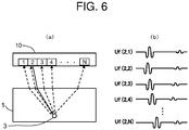
FIG. 6 shows transmission and reception of the ultrasonic waves by the ultrasonic inspection method according to the embodiment. Left side (a) inFIG. 6 is a block diagram and right side (b) is a wave form diagram of received signals by each ultrasonic elements when the ultrasonic is sent by a second ultrasonic element. -
FIG. 7 shows transmission and reception of the ultrasonic waves by the ultrasonic inspection method according to the embodiment. Left side (a) inFIG. 7 is a block diagram and right side (b) is a wave form diagram of received signals by each ultrasonic elements when the ultrasonic is sent by a N-th ultrasonic element. -
FIG. 8 is a conceptual illustration of delay time calculation in the ultrasonic inspection method according to the embodiment. -
FIG. 9 is a diagram illustrating the path of an ultrasonic wave for explanation of Snell's law. -
FIG. 10 is a schematic illustration for explaining an estimated shape reflected wave arrival time in the ultrasonic inspection method according to the embodiment, where the transmitting element number i is 1. -
FIG. 11 is a schematic illustration for explaining an estimated shape reflected wave arrival time in the ultrasonic inspection method according to the embodiment, where the transmitting element number i is 5. -
FIG. 12 is a schematic illustration for explaining an estimated shape reflected wave arrival time in the ultrasonic inspection method according to the embodiment, where the transmitting element number i is 10. -
FIG. 13 shows the first graph for explaining the estimated delay time calculation in the ultrasonic inspection method according to the embodiment. -
FIG. 14 shows the second graph for explaining the estimated delay time calculation in the ultrasonic inspection method according to the embodiment. -
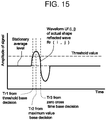
FIG. 15 is a schematic illustration for explaining the extraction of the arrival time in the ultrasonic inspection method according to the embodiment. -
FIG. 16 is a schematic illustration showing the actual shape reflected wave arrival time in the ultrasonic inspection method according to the embodiment, where the transmitting element number i is 1. -
FIG. 17 is a schematic illustration showing the actual shape reflected wave arrival time in the ultrasonic inspection method according to the embodiment, where the transmitting element number i is 5. -
FIG. 18 is a schematic illustration showing the actual shape reflected wave arrival time in the ultrasonic inspection method according to the embodiment, where the transmitting element number i is 10. -
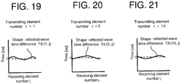
FIG. 19 is a schematic illustration showing the shape reflected wave time difference in the ultrasonic inspection method according to the embodiment, where the transmitting element number i is 1. -
FIG. 20 is a schematic illustration showing the shape reflected wave time difference in the ultrasonic inspection method according to the embodiment, where the transmitting element number i is 5. -
FIG. 21 is a schematic illustration showing the shape reflected wave time difference in the ultrasonic inspection method according to the embodiment, where the transmitting element number i is 10. -
FIG. 22 is a schematic illustration showing the results of the estimated shape reflected wave intensity computation in the ultrasonic inspection method according to the embodiment, where the transmitting element number i is 1. -
FIG. 23 is a schematic illustration showing the results of the estimated shape reflected wave intensity computation in the ultrasonic inspection method according to the embodiment, where the transmitting element number i is 5. -
FIG. 24 m is a schematic illustration showing the results of the estimated shape reflected wave intensity computation in the ultrasonic inspection method according to the embodiment, where the transmitting element number i is 10. -
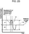
FIG. 25 is a schematic illustration for explaining computation of the reflected wave intensity at a reflected wave intensity extraction step in the ultrasonic inspection method according to the embodiment. -
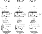
FIG. 26 is a schematic illustration showing the actual shape reflected wave intensity obtained by the actual shape reflected wave intensity extraction step in the ultrasonic inspection method according to the embodiment, where the transmitting element number i is 1. -
FIG. 27 s a schematic illustration showing the actual shape reflected wave intensity obtained by the actual shape reflected wave intensity extraction step in the ultrasonic inspection method according to the embodiment, where the transmitting element number i is 5. -
FIG. 28 s a schematic illustration showing the actual shape reflected wave intensity obtained by the actual shape reflected wave intensity extraction step in the ultrasonic inspection method according to the embodiment, where the transmitting element number i is 10. -
FIG. 29 is a schematic illustration showing the shape reflected wave intensity ratio in the ultrasonic inspection method according to the embodiment, where the transmitting element number i is 1. -
FIG. 30 is a schematic illustration showing the shape reflected wave intensity ratio in the ultrasonic inspection method according to the embodiment, where the transmitting element number i is 5. -
FIG. 31 is a schematic illustration showing the shape reflected wave intensity ratio in the ultrasonic inspection method according to the embodiment, where the transmitting element number i is 10. -
FIG. 32 is a schematic illustration showing the received signals by the ultrasonic elements in the ultrasonic inspection method according to the embodiment for explaining the state where the received wave intensity is corrected on the basis of shape reflected wave time difference after the correction of received wave intensity. -
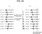
FIG. 33 is a schematic illustration showing the synthesized waves on the basis of shape reflected wave time difference after the correction of received wave intensity in the ultrasonic inspection method according to the embodiment. -
FIG. 34 is a schematic illustration showing the correction of the received waves after the correction of received wave intensity in the ultrasonic inspection method according to the embodiment. -
FIG. 35 is a schematic illustration showing the synthesizing of the received waves after the correction of received wave intensity in the ultrasonic inspection method according to the embodiment. -
FIG. 36 is a schematic illustration showing a single beam for explaining imaging in the ultrasonic inspection method according to the embodiment. -
FIG. 37 is a schematic illustration showing synthesized wave in the ultrasonic inspection method according to the embodiment. -
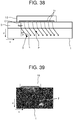
FIG. 38 is a schematic illustration showing a plurality of beams by linear scanning explaining imaging in the ultrasonic inspection method according to the embodiment. -
FIG. 39 is a schematic illustration showing an image for explaining imaging in the ultrasonic inspection method according to the embodiment. - An object of an embodiment of the invention is to reduce the influence of anisotropy of the test object in ultrasonic inspection.
- According to an aspect of the present invention, there is provided an ultrasonic inspection apparatus comprising an ultrasonic array probe having a plurality of ultrasonic elements arranged at predetermined positions for transmitting ultrasonic waves to a test object and receiving ultrasonic waves reflected by a test object; characterized in that the ultrasonic inspection apparatus comprises: an estimated shape-reflected-wave arrival time calculator for computing estimated shape reflected wave arrival time of each of estimated shape reflected waves on basis of estimated sound velocity in the test object, the estimated shape reflected wave arrival time being estimated time for the estimated shape reflected wave to arrive at the ultrasonic element when the ultrasonic wave is reflected at shape-indicating reflection part thereof; an actual shape-reflected-wave arrival time extractor for extracting actual shape reflected wave arrival time on basis of an actual shape reflected wave transmitted from the ultrasonic element used for ultrasonic wave transmission, propagated through the test object, reflected by a shape-indicating reflection part and received by each of the ultrasonic elements used for receiving the ultrasonic wave; a shape-reflected-waves time difference calculator for computing difference obtained by subtracting the actual shape reflected wave arrival time from the estimated shape reflected wave arrival time as shape reflected waves time difference; and a delay time calculator for computing delay times to be used for the purpose of mutually shifting timings of ultrasonic wave transmission and timings of ultrasonic wave reception by the ultrasonic elements, the delay time calculator taking the shape reflected waves time differences into consideration.
- According to another aspect of the present invention, there is provided an ultrasonic inspection method comprising an ultrasonic wave transmitting/receiving step for each of a plurality of ultrasonic elements belonging to an ultrasonic wave array probe to transmit an ultrasonic wave to a test object and receive reflected waves from the test object, characterized in that the ultrasonic inspection method comprises: an estimated shape reflected wave arrival time computing step for an estimated shape-reflected-wave arrival time calculator to calculate the estimated shape reflected wave arrival time on the basis of an estimated sound velocity in the test object; an actual shape reflected wave arrival time extracting step for an actual shape reflected wave arrival extracting section to extract an actual shape reflected wave arrival time on the basis of an actual shape reflected wave transmitted by the ultrasonic element to be used for transmission of an ultrasonic wave, propagated through inside of the test object, reflected by a shape-indicating reflection part and received by the ultrasonic element to be used for reception of the ultrasonic wave; a shape reflected waves time difference computing step for an shape reflected wave time difference computing section to calculate time difference between the estimated shape reflected wave arrival time and the actual shape reflected wave arrival time as shape reflected waves time difference; and a delay time computing step for a delay time calculator to calculate delay times to be used for mutually shifting timings of transmissions and receptions of ultrasonic waves by ultrasonic elements, taking the shape reflected waves time difference into consideration.
- Hereinafter, with reference to the accompanying drawings, embodiments of an ultrasonic inspection apparatus and an ultrasonic inspection method will be described. The same or similar portions are represented by the same reference symbols and will not be described repeatedly.
-
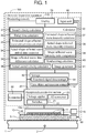
FIG. 1 is a block diagram showing a configuration of an ultrasonic inspection apparatus according to an embodiment. Theultrasonic inspection apparatus 100 nondestructively detects aflaw 2 existing inherently in thetest object 1 by means of ultrasonic waves. Theultrasonic inspection apparatus 100 comprises amonitoring console 110, anultrasonic array probe 10, adrive section 15 for driving theultrasonic array probe 10 and a test objectinformation acquiring section 90. - The
ultrasonic array probe 10 includes a plurality ofultrasonic elements 11 and aholder 12 for holding theultrasonic elements 11. Theultrasonic elements 11 are made of a ceramic material or a composite material. They may typically be piezoelectric elements that can transmit and receive ultrasonic waves by means of the piezoelectric effect thereof, piezoelectric elements that can exploit the piezoelectric effect provided by polymer films or some other elements that can otherwise transmit and receive ultrasonic waves. Each of theultrasonic elements 11 has a damping member for damping ultrasonic waves and a front plate to be fitted to the front surface thereof and may be an element that is generally referred to as an ultrasonic probe. - The
ultrasonic array probe 10 has a total of N (N: natural number)ultrasonic elements 11, arranged at predetermined positions, that transmit ultrasonic waves to thetest object 1 and receive ultrasonic waves reflected and scattered by thetest object 1 or aflaw 2. - In the following description, an
ultrasonic array probe 10 that is generally referred to as linear array probe will be described as an example ofultrasonic array probe 10 having ultrasonic elements arranged at predetermined respective positions. In the linear array probe,ultrasonic elements 11 are one-dimensionally arranged in a first direction. But, the present embodiment is not limited to such an arrangement. Theultrasonic array probe 10 may alternatively be an array probe of some other type provided that the ultrasonic elements are arranged at predetermined positions. Still alternatively, theultrasonic array probe 10 may be one that employs the so-called tandem testing technique of using ultrasonic elements of a plurality of different types in combination. - Ultrasonic array probes of different types include 1.5-dimensional array probes where the ultrasonic elements thereof are divided into groups of different sizes in the depth direction (in the second direction that is perpendicular to the first direction) of the linear array probe, matrix array probes where the
ultrasonic elements 11 thereof are arranged two-dimensionally both in the first direction and in the second direction, ring array probes where the first direction is the direction of a ring and theultrasonic elements 11 thereof are concentrically arranged, split-type ring array probes where the plurality ofultrasonic elements 11 of a ring array probe are circumferentially divided, non-uniform array probes where theultrasonic elements 11 thereof are arranged non-uniformly, arcuate array probes where the first direction is that of an arc and theultrasonic elements 11 thereof are arranged along the circumferential direction thereof at their respective positions and spherical array probes where theultrasonic elements 11 thereof are arranged on a spherical surface. - Note that the
ultrasonic array probe 10 can be made to be usable in any environment such as in a gaseous environment or in a liquid environment when it is caulked, packed or otherwise protected. - The
drive section 15 drives theultrasonic array probe 10 to move around thetest object 1, while typically gripping theholder 12. - A wedge (not shown) may be employed in order to have ultrasonic waves enter the
test object 1 at an angle that makes them show a high directivity. An isotropic material such as an acrylic material, a polyimide material, a gel material, or some other polymer material that can propagate ultrasonic waves and whose acoustic impedance is known may be employed for the wedge. Also, a material whose acoustic impedance is close to or same as the acoustic impedance of the front panel may be used for the wedge. Alternatively, a material whose acoustic impedance is close to or same as the acoustic impedance of thetest object 1 may be used for the wedge. Still alternatively, a composite material that changes its acoustic impedance stepwise or gradually can be used for the wedge. - Additionally, a damping material may be arranged in and out of the wedge, a wave-dissipating member showing a mound-like profile may be arranged and/or a mechanism for reducing multiple reflections may be provided in order to prevent the multiple-reflected waves in the wedge from adversely affecting the results of flaw detection. Note that, in the following description, the wedge that may be employed when causing ultrasonic waves to enter the
test object 1 from theultrasonic array probe 10 is neither described nor illustrated for the purpose of simplicity. - Acoustic coupling is realized, in other words, any sounds can substantially pass entirely through between the
ultrasonic array probe 10 and the wedge, between the wedge and thetest object 1 and between theultrasonic array probe 10 and thetest object 1 when anacoustic propagation medium 5 is disposed there. Theacoustic propagation medium 5 is typically water, glycerin, machine oil, castor oil, acryl, polystyrene, gel or the like, and some other medium can alternatively be used provided that it can propagate ultrasonic waves. Note that, in the following explanation, description of theacoustic propagation medium 5 that is employed to cause ultrasonic waves to enter thetest object 1 from theultrasonic array probe 10 may sometimes be omitted for the purpose of simplicity. - The test object
information acquiring section 90 acquires information on thetest object 1 such as the profile of thetest object 1 and outputs the acquired information to aninput unit 80 in themonitoring console 110. The test objectinformation acquiring section 90 collectively and comprehensively refers to all the means for acquiring information on thetest object 1. More specifically, the test objectinformation acquiring section 90 includes a three-dimensional camera for acquiring appearance data of thetest object 1, measuring means for measuring the temperatures of selected representative spots of thetest object 1 in order to obtain the temperature distribution of thetest object 1, temperature distribution computing means for computationally determining the temperature distribution in thetest object 1 on the basis of the measured temperatures of the selected representative spots and so on. The test objectinformation acquiring section 90 is provided when it is necessary to acquire information on the shape, the dimensions and the temperatures of the parts of thetest object 1 that are not easily accessible. In other words, the test objectinformation acquiring section 90 may not necessarily be provided when the information on thetest object 1 as defined above is already known or when it can be obtained with ease. - The
monitoring console 110 has a reception/transmission section 20, acalculator 30, astorage 50, acontroller 60, adisplay 70 and aninput unit 80. Themonitoring console 110 includes a device having versatile arithmetic operation capabilities and data communication capabilities, which may typically be a PC (personal computer). Themonitoring console 110 may contain the above-listed sections in itself or may be connected to them by way of communication cables. - The reception/
transmission section 20 includes avoltage applier 21, switches 22 and anAD converter 23. - The
voltage applier 21 can apply an electric potential difference that generates vibrations in theultrasonic elements 11. Theswitches 22 bring the selectedultrasonic element 11 and thevoltage applier 21 into an electrically mutually conductive state or into an electrically mutually non-conductive state. In other words, theswitches 22 switch a state where an electric potential difference is applied to the selectedultrasonic element 11 to another state where no electric potential difference is applied to the selectedultrasonic element 11 or vice versa. - The
voltage applier 21 applies a voltage having an arbitrarily selected waveform to theultrasonic elements 11 that are put into an electrically conductive state by theswitches 22. The waveform of the applied voltage may be that of a sine wave, a saw-tooth wave, a rectangular wave, a spike pulse or some other wave. The waveform of the applied voltage may be a so-called bipolar waveform having both positive polarity values and negative polarity values or a unipolar waveform having only positive or negative polarity values. A positive or negative offset value may or may not be added to the waveform. The waveform may be a single pulse waveform, a burst waveform or a continuous waveform. Furthermore, it may be so arranged that the duration of the voltage application can be increased or decreased and/or the number of repetitive waves can be increased or decreased. - Since the reflected waves that the
ultrasonic elements 11 receive provide analog signals, which are continuous signals in terms of time, theAD converter 23 converts the received analog signals into digital signals so that thecalculator 30 can operate for digital processing. - The
input unit 80 receives the inputs from the outside and also from the test objectinformation acquiring section 90. The inputs that theinput unit 80 receives include information relating to the attributes of thetest object 1 such as the shape, the dimensions and the material of thetest object 1, information on the condition of thetest object 1 such as the temperature of thetest object 1 and other pieces of information. The information relating to thetest object 1 that theinput unit 80 receives is stored in the testobject information storage 52 of thestorage 50, which will be described hereinafter. - The
display 70 displays images on the obtained test results and other pieces of information that the inspection staff and other members require, on the basis of the information it receives from the reception/transmission section 20, thecalculator 30 and thestorage 50. Thedisplay 70 displays those images systematically in a given procedural order or on an on-demand basis. Thedisplay 70 may be a liquid crystal display apparatus, a projector, a cathode-ray tube or the like provided that it can display digital data. Thedisplay 70 may have functions such as issuing warning signal in the form of sound or light in response to any of predefined conditions or operating as touch panel having a user interface feature of receiving inputs according to the operations conducted on the touch panel by the user. - The
storage 50 has a processed-signal data storage 51 and a testobject information storage 52. The processed-signal data storage 51 stores the information on the reflected waves, which is digital data on the reflected waves, obtained as a result of the AD conversions executed by theAD converter 23 of the reception/transmission section 20 for the reflected waves received by theultrasonic array probe 10, and the results of the arithmetic processing operations executed at the responsible components of thecalculator 30. The testobject information storage 52 stores the information relating to thetest object 1 received by theinput unit 80. - The
controller 60 monitors the status of the progress of the processing operation of each of the components in themonitoring console 110 so as to make the processing operations of the components in themonitoring console 110 proceed in a coordinated manner as a whole and controls the timing of each of the processing operations. - The
calculator 30 performs processing such as determining the timing of transmission of an ultrasonic wave from each of theultrasonic elements 11 and producing synthetic image data on the basis of the waveforms of the received ultrasonic waves. Thecalculator 30 has asound velocity calculator 31, adelay time calculator 32, an estimated shape-reflected-wavearrival time calculator 33, an actual shape-reflected-wavearrival time extractor 34, an shape-reflected-wavestime difference calculator 35, an actualsound velocity calculator 36, an estimated shape-reflected-wave intensity calculator 37, an actual shape-reflected-wave intensity extractor 38, a shape-reflected-waveintensity ratio comparator 39, a synthesizingcalculator 40 and animage generator 41. - The
sound velocity calculator 31 calculates the estimated sound velocity Vs in thetest object 1 on the basis of the information on the shape, the dimensions, the temperature, the material and so on of thetest object 1 stored in the testobject information storage 52. Thesound velocity calculator 31 assumes that each of thetest object 1 and theacoustic propagation medium 5 is formed by an isotropic material that ensures an uniform sound velocity in it, which uniform sound velocity is not influenced by direction and position, and calculates the estimated sound velocity Vs in each of theobject 1 and theacoustic propagation medium 5. - The
delay time calculator 32 calculates the delay times for shifting the timings of transmissions and the timings of receptions of ultrasonic waves by theultrasonic elements 11 relative to each other on the basis of the virtual delay times and the shape reflected waves time difference, which will be described hereinafter, because the delay times are necessary for causing all the ultrasonic waves transmitted from theultrasonic elements 11 to converge to the focus 3 (FIGS. 2A and 2B ). -
FIG. 2 is a schematic illustration of arrival time calculation in the ultrasonic inspection apparatus according to the embodiment. Left side (a) inFIG. 2 is a block diagram showing a conceptual configuration and right side (b) is a diagram showing the received signals when first to third ultrasonic elements transmit respective ultrasonic waves. Note that the expression of Uf (i, j) or Ufi,j indicates that the waveform is that of the reflected ultrasonic wave transmitted from the i-thultrasonic element 11 and received by the j-thultrasonic element 11. Even if the transmission timings of the first through thirdultrasonic elements 11 are shifted relative to each other so as to cause them to converge to thefocus 3 as shown in left side (a) ofFIG. 2 , the arrival times of the reflection signals vary from each other in a manner as shown in right side (b) ofFIG. 2 , because the propagation time differs among the signal reception paths. - Note that, in such an instance, the
ultrasonic inspection apparatus 100 scans thetest object 1 in the longitudinal direction by sequentially shifting the combination of threeultrasonic elements 11, or the set of threeultrasonic elements 11, such that the combination is firstly (1, 2, 3), secondly (2, 3, 4), thirdly (3, 4, 5) and so on to get to (N-2, N-1, N). -
FIG. 3 is a waveform diagram showing the received signals considering the delay times of the ultrasonic elements according to the embodiment. More specifically, the clock times of the reflected waves in the waveforms Ufi,j of the received waves coincident with each other by taking both the delay times of the transmission side and those of the reception side into consideration. Namely, the arrival clock times of the reflected waves as received by the respectiveultrasonic elements 11 coincident with each other. - The estimated shape-reflected-wave
arrival time calculator 33 calculates the estimated shape reflected wave arrival time Ts (i, j) on the basis of the shape and the dimensions of thetest object 1 stored in the testobject information storage 52 and the estimated sound velocity Vs in theacoustic propagation medium 5, the estimated sound velocity Vs in thetest object 1 and so on calculated by thesound velocity calculator 31. The estimated shape reflected wave arrival time Ts (i, j) is the estimated time during which the ultrasonic wave is transmitted and the estimated shape reflected wave Rs (i, j) of a transmitted ultrasonic wave gets to the reception sideultrasonic element 11. - Note that the expression of estimated shape reflected wave Rs (i, j) refers to a reflected wave that indicates a shape reflected wave that is estimated. The shape reflected wave refers to a received wave that is transmitted from the i-th
ultrasonic element 11 and received by the j-thultrasonic element 11 and the waveform of the received wave includes the waveform of the reflected wave reflected at a shape-indicating reflection part. The reflected wave reflected at a shape-indicating reflection part corresponds to the reflected wave shown inFIG. 3 . - Also note that the expression of a shape-indicating reflection part refers to a part of the
test object 1 that relates to the overall shape of thetest object 1 or a representative part of thetest object 1 in terms of the shape thereof. For example, a shape-indicating reflection part may be the rear surface that is located opposite to the incident surface where ultrasonic waves enter thetest object 1, the interface of two materials of thetest object 1 that differ from each other, a corner or a hole (a cooling hole or the like) in thetest object 1. The shape of a shape-indicating reflection part that is a reflection surface of an ultrasonic wave is not necessarily a plane. - The estimated shape-reflected-wave
arrival time calculator 33 calculates the estimated shape reflected wave arrival time Ts (i, j), which is the time that is required for each of the ultrasonic waves transmitted from anultrasonic element 11 to be received by an ultrasonic element as an estimated shape reflected wave Rs (i, j) on the basis of the estimated sound velocity Vs, the coordinates of each of theultrasonic elements 11 that is used to transmit and receive an ultrasonic wave and the positional relationship of the reflectors of the estimated shape reflected waves Rs (i, j). - The technique to be used for computing the propagation time may be the ray tracing technique that is generally employed for sound source tracking or a technique of numerical analysis such as finite element analysis. The obtained estimated shape reflected wave arrival time is expressed by Ts (i, j).
- The actual shape-reflected-wave
arrival time extractor 34 extracts the actual shape reflected wave arrival time Tr (i, j) on each of the actual shape reflected waves Rr (i, j) stored in the processed-signal data storage 51. Each of the actual shape reflected waves Rr (i, j) is transmitted from the i-th (i = 1, 2, 3, ···, N)ultrasonic element 11 to be used for an ultrasonic wave transmission, propagated in thetest object 1, reflected at a shape-indicating reflection part in thetest object 1 and received by the j -th (j = 1, 2, 3, ···, N) ultrasonic element to be used for an ultrasonic wave reception. In the following description, the expression of (i, j) indicates the combination of the transmission from the i-th ultrasonic element and the reception by the j-the ultrasonic element. - The shape-reflected-waves
time difference calculator 35 calculates a shape reflected waves time difference Td (i, j) by subtracting the actual shape reflected wave arrival time Tr (i, j) from the estimated shape reflected wave arrival time Ts (i, j). - The actual
sound velocity calculator 36 calculates the actual sound velocity Va (i, j) by multiplying the estimated sound velocity Vs (i, j) that thesound velocity calculator 31 has calculated by the ratio of the estimated shape reflected wave arrival time Ts (i, j) to the actual shape reflected wave arrival time Tr (i, j). - The estimated shape-reflected-
wave intensity calculator 37 calculates the estimated shape reflected wave intensity Is (i, j), which is the intensity of the ultrasonic wave received by theultrasonic element 11, by simulating the damping of the ultrasonic wave during the propagation thereof and other factors on the basis of the information relating to thetest object 1 stored in the testobject information storage 52. - The actual shape-reflected-
wave intensity extractor 38 extracts the actual shape reflected wave intensity Ir (i, j) of the actual shape reflected wave Rr (i, j). - The shape-reflected-wave
intensity ratio comparator 39 calculates the ratio of the estimated shape reflected wave intensity Is (i, j) to the actual shape reflected wave intensity Ir (i, j) as shape reflected wave intensities ratio Id (i, j). - The synthesizing
calculator 40 makes the arrival clock times of the reflected waves received by the respectiveultrasonic elements 11 coincide with each other according to their respective delay times and then obtains a synthetic waveform M by synthetically combining those received waves. - The
image generator 41 computationally determines the image data to be displayed on the basis of the synthetic waveform M, the propagation paths of the ultrasonic beams and the sound velocity on the transmission paths. -
FIG. 4 is a flow chart showing a sequence of an ultrasonic inspection method according to the embodiment. - First, the estimated sound velocity is calculated (Step S11). More specifically, the
sound velocity calculator 31 calculates the estimated sound velocity Vs in thetest object 1 and the estimated sound velocity Vs in theacoustic propagation medium 5 on the basis of the information relating to thetest object 1 stored in the testobject information storage 52. - Additionally, the
ultrasonic array probe 10 is set up on the test object 1 (Step S12). At this time, if necessary, anacoustic propagation medium 5 is placed between thetest object 1 and theultrasonic array probe 10. Thedrive section 15 grips the holdingsection 12 of theultrasonic array probe 10 to set up theultrasonic array probe 10 at the predetermined position. - Then, an operation of transmitting and receiving ultrasonic waves is executed in a manner that may vary depending on the inspecting conditions (Step S13). At the time of transmitting ultrasonic waves, an ultrasonic wave is irradiated from one or more of the
ultrasonic elements 11 and received by one or more of theultrasonic elements 11 in theultrasonic array probe 10. Then, as a result, an ultrasonic waveform Uf (i, j) can be obtained by each of the combinations of transmitting and receivingultrasonic elements 11. - Note that the operation of Step S13 needs to be executed after Step S12. However, Step S11 may come before or after Step S12 or Step S13.
-
FIG. 5 shows transmission and reception of the ultrasonic waves by the ultrasonic inspection method according to the embodiment. Left side (a) inFIG. 5 is a block diagram and right side (b) is a wave form diagram of received signals by each ultrasonic elements when the ultrasonic is sent by a first ultrasonic element. Similarly,FIG. 6 shows a block diagram and a wave form diagram when the ultrasonic is sent by a second ultrasonic element, andFIG. 7 shows a bock diagram and a wave form diagram when the ultrasonic is sent by a N-th ultrasonic element. - The ultrasonic waveforms Uf (1, 1) through Uf (1, N) as shown in
FIG. 5 are obtained when an ultrasonic wave is transmitted from the firstultrasonic element 1 and received by the first through N-thultrasonic elements 11. Similarly, the ultrasonic waveforms Uf (2, 1) through Uf (2, N) as shown inFIG. 6 are obtained when an ultrasonic wave is transmitted from the secondultrasonic element 11 and received by the first through N-thultrasonic elements 11. Furthermore, the ultrasonic waveforms Uf (N, 1) through Uf (N, N) as shown inFIG. 7 are obtained when an ultrasonic wave is transmitted from the N-thultrasonic element 11 and received by the first through N-thultrasonic elements 11. - Thus, when the
ultrasonic array probe 10 having Nultrasonic elements 11 is employed and the transmitting element is sequentially shifted while each of the transmitted ultrasonic wave is being received by Nultrasonic elements 11 in the above described manner, N×N ultrasonic wave patterns can maximally be recorded. Note that it is possible to use a singleultrasonic element 11 exclusively for reception and use a plurality ofultrasonic elements 11 only for transmission. Furthermore, it is possible to turn an ultrasonic wave into a plane wave by using the delay time as multiplier and converge or diffuse ultrasonic waves. - The ultrasonic waves that enter the
test object 1 are reflected and scattered by aflaw 2, which may typically be a crack or an inclusion existing in the inside or on the surface of thetest object 1, and the reflected ultrasonic waves are received by theultrasonic elements 11 of theultrasonic array probe 10. - After Step S13, an arithmetic operation for correcting the temporal relations (Step S20) and an arithmetic operation for correcting the intensity relations (Step S30) will be executed. Each of the above-listed arithmetic operations will be described in detail hereinafter. Note that it does not matter if Step S20 comes before or after Step S30.
- For the temporal relations correcting arithmetic operation (Step S20), firstly, the estimated shape-reflected-wave
arrival time calculator 33 calculates the estimated shape reflected wave arrival time (Step S21) for each reflected ultrasonic wave. The estimated shape-reflected-wavearrival time calculator 33 presumes that thetest object 1 has an acoustic characteristic that is uniform and independent of direction and position and estimates the elapsed time since the time when an ultrasonic wave is transmitted from one of theultrasonic elements 11 to the time when it is received as a shape reflected wave by each of theultrasonic elements 11 from the coordinates of theultrasonic element 11 employed for the transmission and also for the reception and also from the positional relationship of the reflector of the estimated shape reflected wave Rs (i, j). -
FIG. 8 is a conceptual illustration of delay time calculation in the ultrasonic inspection method according to the embodiment. For instance, ultrasonic waves are transmitted respectively from a plurality ofultrasonic elements 11, which may be Kultrasonic elements 11 denoted respectively by E1 through EK, in such a fashion that they converge to focus 3. K is 7 in the instance ofFIG. 8 . - Assume here that the propagation length and the propagation velocity at each of the meshes, or mesh k (k = 1, 2, 3, ···, K), located on the propagation path from the i-th
ultrasonic element 11, or Ei, to thefocus 3 are respectively Lk and Vk (k = 1, 2, ···, K). Note that the arithmetic operation of computing the propagation length Lk is based on the use of the center position of theultrasonic element 11. The propagation time T from the i-thultrasonic element 11 to thefocus 3 is determined by means of formula (1) shown below:
- The estimated shape-reflected-wave
arrival time calculator 33 executes calculation on an assumption that each of the materials involved in the calculation is uniform. Stated in a different fashion, when only theacoustic propagation medium 5 and thetest object 1 are involved in the propagation path of an ultrasonic wave from the point where it is transmitted to the point where it is reflected, no mesh division is introduced to them. Namely, K=2. In this instance, an estimated sound velocity Vs is selected for each of theacoustic propagation medium 5 and thetest object 1, and the estimated shape reflected wave arrival time Ts (i, j) is calculated on the basis of the estimated velocities of sound Vs. - When the
acoustic propagation medium 5 is arranged between theultrasonic array probe 10 and thetest object 1, the point at which the ultrasonic wave transmitted from each of theultrasonic elements 11 enters thetest object 1 is computationally determined by using Snell's law and then the transmission time that is required for the propagation is computationally determined by using the sound velocity in theacoustic propagation medium 5 and that in thetest object 1. Thereafter, the delay time is calculated for the ultrasonic wave. -
FIG. 9 is a diagram illustrating the path of an ultrasonic wave for explanation of Snell's law. The path from the starting point Pa in medium A (which corresponds to the acoustic propagation medium 5) to the terminal point Pb in medium B (which corresponds to the test object 1) in the system that includes thetest object 1 can be determined by using Snell's law. Now, assume that the sound velocity in the medium A is VA and the sound velocity in the medium B is VB, while the angle of incidence for an ultrasonic wave to enter from the medium A into the medium B is θA and the angle of refraction is θB. Then, as for the path from the starting point Pa in the medium A to the terminal point Pb in the medium B, an incidence point W that satisfies the requirement of formula (2) shown below can be determined. Then, as a result, the path can be determined.
- In the case that surface profile S of the
test object 1 is not an ordinary plane or an inclined plane but those having a certain radius of curvature or undulations or some other complex profile, geometrical calculations can be performed. Geometrical calculations for such a complex surface profile can be performed by considering information on the incident angle at the point, on the surface of thetest object 1, where the ultrasonic wave enters, in the computation of the incident point W that uses Snell's law. The surface profile S of thetest object 1 is included in the test object-related information, stored in the testobject information storage 52, input from the test objectinformation acquiring section 90 or directly from outside into theinput unit 80. -
FIG. 10 is a schematic illustration for explaining an estimated shape reflected wave arrival time in the ultrasonic inspection method according to the embodiment. As shown in upper side (a) in each ofFIGS. 10, 11 and 12, FIG. 10 shows a case where the transmitting element number i is 1,FIG. 11 shows a case where the transmitting element number i is 5, andFIG. 12 shows a case where the transmitting element number i is 10. In lower side (b) in each ofFIGS. 10, 11 and 12 , the horizontal axis indicates the number (i) of the receivingultrasonic element 11 and the vertical axis, where "time [µs]'' is shown, indicates the estimated shape reflected wave arrival time Ts (i, j). - As shown in
FIGS. 10 through 12 , the ultrasonic wave that is generated from one of the ultrasonic elements is reflected at a shape-indicating part of thetest object 1 and received by each of theultrasonic elements 11 as estimated shape reflected wave Rs (i, j). Each ofFIGS. 10 through 12 shows an instance where the bottom surface, which is the rear surface opposite to the surface of thetest object 1 through which the ultrasonic wave enters thetest object 1, is the shape-indicating part. - The ultrasonic wave that is transmitted from the i-th
ultrasonic element 11, reflected at the shape-indicating part and received by the j-thultrasonic element 11 is obtained as estimated shape reflected wave Rs (i, j). The time at which the ultrasonic wave that is transmitted from the i-thultrasonic element 11 and reflected at the shape-indicating part so as to become the estimated shape reflected wave Rs (i, j) arrives at the ultrasonic wave receiving j-thultrasonic element 11 is given as estimated shape reflected wave arrival time Ts (i, j). The estimated shape reflected wave arrival time Ts (i, j) is equal to the sum of the quotient calculated by dividing the length of the path in theacoustic propagation medium 5 by the estimated sound velocity Vs there and the quotient calculated by dividing the length of the path in thetest object 1 by the estimated sound velocity Vs there. - When the transmitting element number i is equal to 1, the length of the path getting to the receiving ultrasonic element whose receiving element number j is equal to 1 is shortest and the estimated shape reflected wave arrival time Ts (1, 1) of that ultrasonic element is also shortest among all the estimated shape reflected wave arrival times Ts (1, j), as shown in
FIG. 10 . When the transmitting element number i is equal to 5, the length of the path getting to the receiving ultrasonic element whose receiving element number j is equal to 5 is shortest and the estimated shape reflected wave arrival time Ts (5, 5) of that ultrasonic element is also shortest among all the estimated shape reflected wave arrival times (5, j), as shown inFIG. 11 . Likewise, when the transmitting element number i is equal to 10, the length of the path getting to the receiving ultrasonic element whose receiving element number j is equal to 10 is shortest and the estimated shape reflected wave arrival time Ts (10, 10) of that ultrasonic element is also shortest among all the estimated shape reflected wave arrival times (10, j) as shown inFIG. 12 . In other words,FIGS. 10 to 12 show that the shape-indicating part is at the bottom surface, which is the bottom surface of a flat plate, and hence, if echoes from the bottom surface of the flat plate are assumed, the path length is shortest and the arrival time is shortest when i = j. - Then, the
delay time calculator 32 calculates the estimated delay time (Step S22). -
FIG. 13 shows the first graph for explaining the estimated delay time calculation in the ultrasonic inspection method according to the embodiment. The number ofultrasonic elements 11 that participate in transmission and reception of ultrasonic waves is equal to 7 as in the instance ofFIG. 8 . InFIG. 13 , the vertical axis indicates the propagation time of ultrasonic wave from the focus 3 (FIG. 8 ) to each of theultrasonic elements 11. - When both the estimated sound velocity Vs in the
acoustic propagation medium 5 and the estimated sound velocity Vs in thetest object 1 are assumed to be constant and ultrasonic waves are made to converge to thefocus 3 by using a plurality of ultrasonic elements 11 (e.g., seven including E1 through E7 inFIG. 8 ) of theultrasonic array probe 10 as shown inFIG. 8 , the estimated delay times are the delay times that are assigned to the respectiveultrasonic elements 11. Since both the estimated sound velocity Vs in theacoustic propagation medium 5 and the estimated sound velocity Vs in thetest object 1 are assumed to show respective constant values, the estimated delay times can be determined on the basis of geometric information including the order of arrangement and the positions of the operated plurality ofultrasonic elements 11 of theultrasonic array probe 10, the position of thefocus 3 relative to the ultrasonic array probe 10 (the angle and the depth of the flaw detection) and so on. In other words, the estimated delay times are delay times that are estimated on the basis of the geometric profile of thetest object 1 and on an assumption that both the estimated sound velocity Vs in theacoustic propagation medium 5 and the estimated sound velocity Vs in thetest object 1 show respective constant values. - Referring to
FIG. 8 , since E1 is located remotest from thefocus 3, the propagation time to thefocus 3 becomes longest when E1 is theultrasonic element 11 that transmits an ultrasonic wave, whereas the propagation time to thefocus 3 when each of E2 through E7 is operated as theultrasonic element 11 that transmits an ultrasonic element is shorter than the propagation time for E1. InFIG. 13 , the propagation time for each of theultrasonic elements 11 is indicated by a solid line and the estimated delay time for Ei that is the value obtained by subtracting the propagation time for Ei from the propagation time for E1 is indicated by a broken line. -
FIG. 14 shows the second graph for explaining the estimated delay time calculation in the ultrasonic inspection method according to the embodiment. This graph shows the estimated delay time for each of theultrasonic elements 11 that is shown by a broken line inFIG. 13 . - As a result of assigning estimated delay times respectively to a plurality of
ultrasonic elements 11 of theultrasonic array probe 10, it is now possible for the plurality ofultrasonic elements 11 to respectively transmit and receive ultrasonic waves that converge to thefocus 3 provided that the estimated sound velocity Vs in theacoustic propagation medium 5 is assumed to be constant and also the estimated sound velocity Vs in thetest object 1 is assumed to be constant. Note that, for this operation, it is possible to define a reference point in advance on the basis of the positional arrangement of the plurality ofultrasonic elements 11 to be operated. Additionally, when such a reference point is to be defined, theultrasonic array probe 10 can be handled such that ultrasonic beams are transmitted from the reference point to thefocus 3 and received at the reference point by each of the plurality ofultrasonic elements 11. - Next, the actual shape-reflected-wave
arrival time extractor 34 extracts the actual shape reflected wave arrival time (Step S23). -
FIG. 15 is a schematic illustration for explaining the extraction of the arrival time in the ultrasonic inspection method according to the embodiment. As shown inFIG. 15 , on the basis of the waveform Uf (i, j) of the actual shape reflected wave Rr (i, j) stored in the signal processinginformation storage section 51, the actual shape-reflected-wavearrival time extractor 34 extracts the information relating to the arrival time of the ultrasonic wave that includes this waveform and determines the arrival time. - Now, as an example, let's take an example where the typical waveform of the actual shape reflected wave Rr (i, j) is a pulse-shaped wave that has a simple waveform, and the pulse wave rises up at the positive side and then falls down to the negative side. The techniques that can be used to determine the arrival time will be described below.
- With the first technique, the time when the first pulse at the positive side arrives at a threshold value for the first time is selected as an arrival time Tr1 of the actual shape reflected wave Rr (i, j).
- With the second technique, the time when the first pulse at the positive side gets to the maximum value is selected as an arrival time Tr2 of the actual shape reflected wave Rr (i, j).
- With the third technique, the time when the first pulse at the positive side is turned into the negative side, which is more specifically the time when the first pulse at the positive side intersects the stationary average level of the received signal is selected as an arrival time Tr3 of the actual shape reflected wave Rr (i, j).
- Note, however, any technique other than the above-described ones can be adopted so long as it can reliably determine the arrival time. An extraction method is commonly employed for the group of waveforms Uf (i, j) (i, j = 1, ···. N) that are obtained in a single measurement session. While it is desirable that such an extraction method can also commonly be employed for the waveforms Uf (i, j) that are obtained in mutually different measurement sessions, the present invention is by no means limited to such a common use of an extraction method. Since the determining method is not subject to limitations, the component of the
computing section 30 that is employed for this step is referred to as the actual shape-reflected-wavearrival time extractor 34. -
FIG. 16 is a schematic illustration showing the actual shape reflected wave arrival time in the ultrasonic inspection method according to the embodiment, where the transmitting element number i is 1.FIG. 17 is a schematic illustration where the transmitting element number i is 5.FIG. 18 is a schematic illustration where the transmitting element number i is 10. In each ofFIGS. 16, 17 and 18 , the actual shape reflected wave arrival time is indicated by a solid line and the estimated shape reflected wave arrival time is indicated by a broken line for the purpose of ease of comparison. Since the estimated sound velocity Vs in theacoustic propagation medium 5 and the estimated sound velocity Vs in thetest object 1 are assumed to have each constant values, the path length is the single determinant factor of the propagation time so that the estimated shape reflected wave arrival time Ts (i, j) for theultrasonic element 11 whose receiving element number j is expressed by a relatively simple relation formula. - On the other hand, when the
test object 1 is made of an anisotropic material that gives variances in the sound velocity as a function of position and direction or when thetest object 1 has a temperature distribution inside thereof, he actual sound velocity Va in thetest object 1 can delicately vary depending on the position in thetest object 1. If such is the case, the path of an ultrasonic wave will be deviated from a linear path. Then, as a result, the actual shape reflected wave arrival time Tr (i, j) of each of theultrasonic element 11 having a receiving element number j that is obtained on the basis of the actual response waveform Uf (i, j) will also be deviated from the corresponding estimated shape reflected wave arrival time Ts (i, j). - Thereafter, the shape-reflected-waves
time difference calculator 35 calculates the shape reflected waves time difference (Step S24). To be more accurate, the shape-reflected-wavestime difference calculator 35 calculates the shape reflected waves time difference Td (i, j) between the estimated shape reflected wave arrival time Ts (i, j) obtained by the estimated shape-reflected-wavearrival time calculator 33 and the actual shape reflected wave arrival time Tr (i, j) obtained by the actual shape-reflected-wavearrival time extractor 34. More specifically, the shape-reflected-wavestime difference calculator 35 calculates the difference between the actual shape reflected wave arrival time Tr (i, j) and the estimated shape reflected wave arrival time Ts (i, j) of each combination of same elements to obtain the shape reflected waves time difference Td (i, j) for the combination of elements. -
FIG. 19 is an illustration of the shape reflected waves time difference for the transmitting element number i = 1. Similarly,FIG. 20 is for the transmitting element number i=5 andFIG. 21 is for the transmitting element number i = 10. As seen fromFIGS. 19 through 21 , the shape reflected waves time difference Td (i, j) can take both positive polarity values and negative polarity values. - The obtained shape reflected waves time difference Td (i, j) can be reflected to the scheme for obtaining a synthetic waveform M. As described above, since the estimated delay time is calculated on the basis of the estimated sound velocity Vs that is obtained on an assumption that the
test object 1 is made of an isotropic material, it is not possible to obtain an ideal synthetic wave M if thetest object 1 shows anisotropy. For this reason, thedelay time calculator 32 calculates the delay time after executing a corrective operation of adding or subtracting the shape reflected waves time difference Td (i, j) to or from the estimated delay time. In this way, thedelay time calculator 32 calculates the delay time by taking the shape reflected waves time difference Td (i, j) into consideration for the estimated delay time and the synthesizingcalculator 40 executes a synthesizing arithmetic operation on the received waves received by the respectiveultrasonic elements 11 according to the delay time so that consequently it is possible to obtain a synthetic waveform M where the influence of anisotropy is minimized. - The shape reflected waves time difference Td (i, j) is obtained by subtracting the estimated shape reflected wave arrival time Ts (i, j) from the actual shape reflected wave arrival time Tr (i, j). Therefore, when the shape reflected waves time difference Td (i, j) is a negative value, it means that the actual shape reflected wave presumably arrives earlier than the estimated arrival time and hence the delay time will be obtained as an increment. When, to the contrary, the actual shape reflected wave presumably arrives later than the estimated arrival time, the delay time will be obtained as a decrement. The shape reflected waves time difference Td (i, j) can be used as correction value for the synthesizing arithmetic operation.
- When the distances from the
ultrasonic elements 11 to thefocus 3 are significantly shorter than the distances from theultrasonic elements 11 to the shape-indicating site that gives rise to estimated shape reflected waves Rs (i, j), for example when the depth of thefocus 3 is shallow relative to the rear surface, and the shape reflected waves time difference Td (i, j) is simply added to or subtracted from the estimated delay time, the correction value that is obtained by taking the shape reflected waves time difference Td (i, j) into consideration can become too large. If such is the case, the shape reflected waves time difference Td (i, j) may be multiplied by a weighting factor before it is added to or subtracted from the estimated delay time for the computation of the delay time by thedelay time calculator 32. Such a weighting factor can be determined on the basis of the ratio of the distance from theultrasonic element 11 to thefocus 3 to the distance from theultrasonic element 11 to the shape-indicating site. Otherwise, it can appropriately be determined in advance by means of experiments or simulations. The weighting factor may be provided as a function of the ratio of the distance from theultrasonic element 11 to the shape-indicating site to the distance from theultrasonic element 11 to thefocus 3. - Subsequently, the actual
sound velocity calculator 36 calculates the actual sound velocity (Step S25). - Both of the reflected wave for which the estimated shape reflected wave arrival time Ts (i, j) is obtained in Step S21 and the reflected wave for which the actual shape reflected wave arrival time Tr (i, j) is obtained in Step S23 came through the substantially same propagation path from the viewpoint of approximation when the transmitting element number i and the receiving element numbers j agree with each other. Therefore, the actual
sound velocity calculator 36 can estimate the actual sound velocity Va (i, j) from the ratio of the actual shape reflected wave arrival time Tr (i, j) to the estimated shape reflected wave arrival time Ts (i, j). - When the value obtained by normalizing the actual shape reflected wave arrival time Tr (i, j) by the estimated shape reflected wave arrival time Ts (i, j) is 2, for example, the actual sound velocity Va (i, j) can be determined (0.5 Vi) by multiplying Vi by the reciprocal number of the value. If the propagation path is made to have a part where the sound velocity is reliably constant (e.g. an acoustic propagation medium), the ratio need to be determined by using the value obtained by subtracting the propagation time in the acoustic propagation medium. Since the obtained actual sound velocity Va (i, j) corresponds to the combination of the transmitting ultrasonic element and the receiving ultrasonic element, the actual sound velocity Va (i, j) can be used for the computation of the delay time in instances where the transmitted waveform and the received waveform of the corresponding ultrasonic elements are employed.
- The obtained actual sound velocity Va (i, j) can also be used as the sound velocity in the
test object 1 for the arithmetic operation for obtaining the flaw image. In other words, the change with time of the waveform at each of the positions in thetest object 1 can be calculated by using the actual sound velocity Va (i, j) and the path length to each of the positions after the ultrasonic wave transmission to the position. - On the other hand, as intensity-related correction value computation (Step S30), firstly, the estimated shape-reflected-
wave intensity calculator 37 calculates the estimated shape reflected wave intensity (Step S31). - The estimated shape-reflected-
wave intensity calculator 37 assumes that thetest object 1 is made of an isotropic material having a uniform acoustic characteristic that is independent of direction and position. Then, the estimated shape-reflected-wave intensity calculator 37 estimates the intensity of the ultrasonic wave transmitted from each of theultrasonic elements 11 and received by each of theultrasonic elements 11 as shape reflected wave, on the basis of the coordinates of each of theultrasonic elements 11 used for transmission and reception of ultrasonic wave and the positional relationship between the estimated reflected wave Rs (i, j) and the reflector. - In the estimation, the frequency of the ultrasonic wave that enters the
test object 1, the propagation damping according to the elastic characteristic of thetest object 1, the diffusion damping due to broadening of the sound field, the shape of the shape-indicating site where the estimated shape reflected wave Rs (i, j) is produced as a result of reflection and the mode conversion efficiency of the conversion from the longitudinal wave to the transverse wave and other factors are taken into consideration. The technique to be used for the estimation may be the ray tracing technique that is generally being employed for sound source tracking or a technique of numerical analysis such as a technique of finite element analysis. The sound source of the estimated shape reflected wave Rs (i, j) to be used for the computation is not limited to the reflected wave from the bottom surface shown above as an example but may be those from a corner or a hole (a cooling hole or the like) made in thetest object 1 as in the instance of the estimated shape-reflected-wavearrival time calculator 33 described above for Step S21. In this way, the estimated shape-reflected-wave intensity calculator 37 calculates the estimated shape reflected wave intensity Is (i, j). -
FIG. 22 is a schematic illustration showing the results of the estimated shape reflected wave intensity computation in the ultrasonic inspection method according to the embodiment, where the transmitting element number i is 1.FIG. 23 is a schematic illustration, where the transmitting element number i is 5.FIG. 24 m is a schematic illustration, where the transmitting element number i is 10. As seen fromFIGS. 22, 23 and 24 , when a bottom surface echo of a flat plate is assumed, the path length that contributes to damping and other phenomena is minimal and the estimated shape reflected wave intensity Is (i, j) is maximal when i=1. - Then, the actual shape-reflected-
wave intensity extractor 38 extracts the actual shape reflected wave intensity Ir (i, j) (Step S32). -
FIG. 25 is a schematic illustration for explaining computation of the reflected wave intensity at a reflected wave intensity extraction step in the ultrasonic inspection method according to the embodiment. - As shown in
FIG. 25 , the actual shape-reflected-wave intensity extractor 38 calculates the intensity Ir (i, j) of the reflected wave part of the waveform Uf (i, j) of the actual shape reflected wave Rf (i, j) on the basis of the waveform Uf (i, j) of the actual shape reflected wave Rf (i, j) stored in the signal processinginformation storage section 51. - Assume that a pulse wave rises up to the positive side and then falls down to the negative side as a waveform obtained by simplifying the typical waveform Uf (i, j) of the actual shape reflected wave Rr (i, j), as in Step S23. The techniques that can be used to determine the intensity will be described below as so many examples.
- AS for the first technique, the absolute value Ir1 of the difference between the first positive side peak value and the stationary average level of the waveform Uf (i, j) is adopted as the value of the intensity Ir (i, j).
- AS for the second technique, the absolute value Ir2 of the difference between the stationary average level and the negative side peak value of the waveform Uf (i, j) is adopted as the value of the intensity Ir (i, j).
- AS for the third technique, the absolute value Ir3 of the difference between the positive side peak value and the negative side peak value of the waveform Uf (i, j) is adopted as the value of the intensity Ir (i, j).
- AS for the fourth technique, in the waveform Uf (i, j), the absolute value Ir4 of the result obtained by time integration of a certain time domain is adopted as the value of the actual shape reflected wave intensity Ir (i, j). Either a time interval extending from before to after the clock time of the occurrence of the positive side peak value or a time interval extending from before to after the clock time of the occurrence of the negative side peak value may be used for the time integration.
- Any technique other than the above listed ones may alternatively be employed so long as such a technique can provide such results that are decided stably. A same intensity extracting method is commonly employed for the group of waveforms Uf (i, j) (i, j = 1, ···, N) obtained in a single measurement session. A same intensity extracting method is preferably but not necessarily employed for the waveforms Uf (i, j) obtained in different measurement sessions. Since the method for determining the intensity is not subject to any limitations, the component of the
computing section 30 that is operated in this step is referred to as actual shape-reflected-wave intensity extractor 38. -
FIG. 26 is a schematic illustration showing the actual shape reflected wave intensity obtained by the actual shape reflected wave intensity extraction step in the ultrasonic inspection method according to the embodiment, where the transmitting element number i is 1.FIG. 27 s a schematic illustration, where the transmitting element number i is 5.FIG. 28 s a schematic illustration, where the transmitting element number i is 10. - In each of
FIG. 26, FIG. 27 and FIG. 28 , the actual shape reflected wave intensity Ir (i, j) is indicated by a solid line and the estimated shape reflected wave intensity Is (i, j) is indicated by a broken line for the purpose of comparison. As shown inFIGS. 26, 27 and 28 , when thetest object 1 is made of an anisotropic material that gives variances in the sound velocity as a function of position and direction, the curve of the actual shape reflected wave intensity Ir (i, j) and the curve of the estimated shape reflected wave intensity Is (i, j) do not agree with each other. - The shape-reflected-wave
intensity ratio comparator 39 then calculates the shape reflected wave intensities ratio (Step S33). More specifically, the shape-reflected-waveintensity ratio comparator 39 calculates the ratio of Ir (i, j) obtained by the actual shape-reflected-wave intensity extractor 38 relative to Is (i, j) obtained by the estimated shape-reflected-wave intensity calculator 37. The value obtained by normalizing Ir (i, j) by Is (i, j) for the combination of same elements is employed as the shape reflected wave intensities ratio Id (i, j). -
FIG. 29 illustrate the shape reflected wave intensities ratio Id (i, j).FIG. 29 shows an instance where the transmitting element number is i = 1,FIG. 30 shows an instance where the transmitting element number is i = 5, andFIG. 31 shows an instance where the transmitting element number is i = 10. As seen fromFIGS. 29 through 31 , the shape reflected wave intensities ratio Id (i, j) can take positive values that are centered at 1. - Then, the correction gain Gc (i, j) of each waveform Uf (i, j) to be used for the arithmetic operation for obtaining the synthetic waveform M is calculated on the basis of the shape reflected wave intensities ratio Id (i, j). For example, the reciprocal of the shape reflected wave intensities ratio Id (i, j) may be selected as the correction gain Gc (i, j). Then, the magnitude of the damping may be decreased depending on the propagation path by selecting and multiplying the waveform Uf (i, j) by the correction gain.
- Note that the arithmetic operation for the time-related correction (Step S20) is independent of the arithmetic operation for the intensity-related correction (Step S30), and the intensity-related correction is not indispensable for the synthesis of the waveform Uf (i, j) of the actual shape reflected wave Rr (i, j) by the synthesizing
calculator 40. In other words, the synthesizingcalculator 40 can effectively operate for the synthesis even when the intensity-related correction has not been done. - After both the arithmetic operation for the time-related correction (Step S20) and the arithmetic operation for the intensity-related correction (Step S30) are carried out in a manner as described above, the operation of the waveform Uf (i, j) synthesis and the operation of imaging the synthetic waveform data are executed (Step S40).
- Firstly, the synthesizing
calculator 40 corrects the waveform whose intensity has been corrected according to the corrected delay time and then the synthesizingcalculator 40 executes the synthesizing operation (Step S41). With regard to the intensity-related correction, the synthesizingcalculator 40 executes the correcting operation by means of the correction gain Gc (i, j) obtained by the shape-reflected-waveintensity ratio comparator 39 in the shape reflected wave intensities ratio computing step S33. Note that additions, averaging or some other synthesizing techniques may be employed for the synthesizing operation. - With regard to the time-related correction, the synthesizing
calculator 40 firstly allocates the delay times that have been corrected by the actualsound velocity calculator 36 in the actual sound velocity computing step S25 to theultrasonic elements 11 that constitutes the group of drive elements. Then, the synthesizingcalculator 40 executes the synthesizing operation to obtain the synthetic waveform M by respectively shifting the received signals obtained by theultrasonic elements 11 by the delay times allocated to theultrasonic elements 11 in the direction of the time axis. -
FIG. 32 is a schematic illustration showing the received signals by the ultrasonic elements in the ultrasonic inspection method according to the embodiment for explaining the state where the received wave intensity is corrected on the basis of shape reflected wave time difference after the correction of received wave intensity. Left part ofFIG. 32 shows the waveforms Uf (i, j) before the execution of the intensity-related corrections for the respectiveultrasonic elements 11. Right part ofFIG. 32 shows the waveforms Uf (i, j) after the execution of the corrections by means of the correction gains Gc (i, j) for the respectiveultrasonic elements 11. -
FIG. 33 is a schematic illustration showing the synthesized waves on the basis of shape reflected wave time difference after the correction of received wave intensity in the ultrasonic inspection method according to the embodiment.FIG. 34 is a schematic illustration showing the correction of the received waves after the correction of received wave intensity in the ultrasonic inspection method according to the embodiment. As the received signals are shifted in the direction of the time axis by the sum of the delay time for transmission and the delay time for reception, the timings of the reflected waves from the flaw-indicating echoes that are attributable to theflaw 2 are aligned and the signal intensities are boosted as a result of the synthesizing operation. -
FIG. 35 is a schematic illustration showing the synthesizing of the received waves after the correction of received wave intensity in the ultrasonic inspection method according to the embodiment. - Thereafter, the operation of imaging the synthetic waveform data is executed (Step S42).
-
FIG. 36 is a schematic illustration showing a single beam for explaining imaging in the ultrasonic inspection method according to the embodiment.FIG. 37 is a schematic illustration showing synthesized wave in the ultrasonic inspection method according to the embodiment. As shown inFIG. 36 , a synthetic waveform M as shown inFIG. 37 is obtained by the above-described sequence of operations on the basis of the results of transmissions of ultrasonic waves that are focused to a predetermined position in thetest object 1, for example, to therear surface 1a, as a shape-indicating part of thetest object 1 as shown inFIG. 36 . -
FIG. 38 is a schematic illustration showing a plurality of beams by linear scanning explaining imaging in the ultrasonic inspection method according to the embodiment. - In
FIG. 38 , a plurality of beams produced by a linear scanning operation is shown to illustrate the imaging operation. Ultrasonic beams are sequentially shifted in the longitudinal direction for a linear scanning operation and a synthetic waveform M is obtained at each of the beam positions. - For the
image generator 41 to prepare imaging data on the basis of the results of the linear scanning operation, it employs information on the delay time of each of theultrasonic elements 11 to be used for the above-described waveform synthesis, on the ultrasonic beam propagation path L that is the path by way of which the synthetic waveform M propagates and on the actual sound velocity Va in the domain where the ultrasonic beam propagation path L runs among others in addition to the synthetic waveform M. The ultrasonic beam propagation path L is the sound propagation line that runs from the coordinates of the center C of theultrasonic element 11 to be used for the synthesis to thefocus 3 in thetest object 1 and the point at which the ultrasonic wave enters from theacoustic propagation medium 5 into thetest object 1 can be determined by means of Snell's law as in the instance of delay time computations. The synthetic waveform M moves on the ultrasonic beam propagation path L with time. In other words, the synthetic waveform M may be considered to develop along the ultrasonic beam propagation path L. - Therefore, the intensity of the ultrasonic wave at an arbitrarily selected position in the
test object 1 can be calculated on the basis of the synthetic waveform M for the ultrasonic beam propagation path L that passes that position P. More specifically, the change with time of the waveform of the transmitted ultrasonic wave at the position P in thetest object 1 can be computationally determined by using the actual sound velocity Va (i, j) and the path length to the position P on the ultrasonic beam propagation path L after the transmission. - A major part of the synthetic waveform M shown in
FIGS. 36 and 37 is the part thereof that propagates through theacoustic propagation medium 5 and the actual sound velocity Va in theacoustic propagation medium 5 is low if compared with the actual sound velocity Va in thetest object 1. Therefore, if the synthetic waveform M is drawn along the ultrasonic beam propagation path L, the part thereof in theacoustic propagation medium 5 is smaller than the part thereof in thetest object 1. -
FIG. 39 is a schematic illustration showing an image for explaining imaging in the ultrasonic inspection method according to the embodiment. Image data are prepared by theimage generator 41 and an image as shown inFIG. 39 may be displayed on thedisplay 70. - As described above, the
ultrasonic inspection apparatus 100 according to the present embodiment can reduce the influence of anisotropy of the test object in ultrasonic flaw detection. - While the embodiments of the present invention have thus been described, the embodiments are presented as examples and are not intended to limit the scope of the invention.
- Furthermore, the above-described embodiments may be put to use in various different ways and, if appropriate, any of the components thereof may be omitted, replaced or altered in various different ways without departing from the spirit and scope of the invention. All the above-described embodiments and the modifications made to them are within the spirit and scope of the present invention, which is specifically defined by the appended claims, as well as their equivalents.
Claims (6)
- An ultrasonic inspection apparatus (100) comprising an ultrasonic array probe (10) having a plurality of ultrasonic elements (11) arranged at predetermined positions for transmitting ultrasonic waves to a test object (1) and receiving ultrasonic waves reflected by a test object (1); characterized in that
the ultrasonic inspection apparatus (100) comprises:an estimated shape-reflected-wave arrival time calculator (33) for computing estimated shape reflected wave arrival time of each of estimated shape reflected waves on basis of estimated sound velocity in the test object (1), the estimated shape reflected wave arrival time being estimated time for the estimated shape reflected wave to arrive at the ultrasonic element (11) when the ultrasonic wave is reflected at shape-indicating reflection part thereof;an actual shape-reflected-wave arrival time extractor (34) for extracting actual shape reflected wave arrival time on basis of an actual shape reflected wave transmitted from the ultrasonic element (11) used for ultrasonic wave transmission, propagated through the test object (1), reflected by a shape-indicating reflection part and received by each of the ultrasonic elements (11) used for receiving the ultrasonic wave;a shape-reflected-waves time difference calculator (35) for computing difference obtained by subtracting the actual shape reflected wave arrival time from the estimated shape reflected wave arrival time as shape reflected waves time difference; anda delay time calculator (32) for computing delay times to be used for the purpose of mutually shifting timings of ultrasonic wave transmission and timings of ultrasonic wave reception by the ultrasonic elements (11), the delay time calculator (32) taking the shape reflected waves time differences into consideration. - The ultrasonic inspection apparatus (100) according to claim 1, wherein
the delay time calculator (32) is configured to multiply the shape reflected waves time difference by a weighting factor. - The ultrasonic inspection apparatus (100) according to claim 1 or 2, further comprising:
a synthesizing calculator (40) for computationally determining a synthetic waveform of the waves received by the ultrasonic elements (11). - The ultrasonic inspection apparatus (100) according to claim 3, further comprising:an estimated shape-reflected-wave intensity calculator (37) for computing an estimated shape reflected wave intensity that is an intensity of the estimated shape reflected wave;an actual shape-reflected-wave intensity extractor (38) for extracting an actual shape reflected wave intensity that is the intensity of the actual shape reflected wave; anda shape-reflected-wave intensity ratio comparator (39) for computing a ratio of the estimated shape reflected wave intensity to the actual shape reflected wave intensity as correction gain; whereinthe synthesizing calculator (40) computationally determining the synthetic waveform after correcting the waves received by the ultrasonic elements (11) respectively by the correction gains.
- The ultrasonic inspection apparatus (100) according to claim 3 or 4, further comprising:an actual sound velocity calculator (36) for computing an actual sound velocity by multiplying the estimated sound velocity by a ratio of the estimated shape reflected wave arrival time to the actual shape reflected wave arrival time; andan image generator (41) for computationally determining an image data to be displayed by using the synthetic waveform and causing the actual sound velocity to be reflected to the image data.
- An ultrasonic inspection method comprising
an ultrasonic wave transmitting/receiving step for each of a plurality of ultrasonic elements (11) belonging to an ultrasonic wave array probe (10) to transmit an ultrasonic wave to a test object (1) and receive reflected waves from the test object (1), characterized in that
the ultrasonic inspection method comprises:an estimated shape reflected wave arrival time computing step for an estimated shape-reflected-wave arrival time calculator (33) to calculate the estimated shape reflected wave arrival time on the basis of an estimated sound velocity in the test object (1);an actual shape reflected wave arrival time extracting step for an actual shape reflected wave arrival extracting section to extract an actual shape reflected wave arrival time on the basis of an actual shape reflected wave transmitted by the ultrasonic element (11) to be used for transmission of an ultrasonic wave, propagated through inside of the test object (1), reflected by a shape-indicating reflection part and received by the ultrasonic element (11) to be used for reception of the ultrasonic wave;a shape reflected waves time difference computing step for an shape reflected wave time difference computing section to calculate time difference between the estimated shape reflected wave arrival time and the actual shape reflected wave arrival time as shape reflected waves time difference; anda delay time computing step for a delay time calculator (32) to calculate delay times to be used for mutually shifting timings of transmissions and receptions of ultrasonic waves by ultrasonic elements (11), taking the shape reflected waves time difference into consideration.
Applications Claiming Priority (1)
| Application Number | Priority Date | Filing Date | Title |
|---|---|---|---|
| JP2018020139A JP6926011B2 (en) | 2018-02-07 | 2018-02-07 | Ultrasonic flaw detector and ultrasonic flaw detection method |
Publications (2)
| Publication Number | Publication Date |
|---|---|
| EP3524974A1 true EP3524974A1 (en) | 2019-08-14 |
| EP3524974B1 EP3524974B1 (en) | 2024-10-09 |
Family
ID=65023803
Family Applications (1)
| Application Number | Title | Priority Date | Filing Date |
|---|---|---|---|
| EP19151662.4A Active EP3524974B1 (en) | 2018-02-07 | 2019-01-14 | Ultrasonic inspection apparatus and ultrasonic inspection method |
Country Status (6)
| Country | Link |
|---|---|
| US (1) | US10942154B2 (en) |
| EP (1) | EP3524974B1 (en) |
| JP (1) | JP6926011B2 (en) |
| CN (1) | CN110118822B (en) |
| FI (1) | FI3524974T3 (en) |
| RU (1) | RU2702804C1 (en) |
Cited By (1)
| Publication number | Priority date | Publication date | Assignee | Title |
|---|---|---|---|---|
| US20230036761A1 (en) * | 2021-07-30 | 2023-02-02 | Neptune Technology Group Inc. | Method and system for transducer validation |
Families Citing this family (7)
| Publication number | Priority date | Publication date | Assignee | Title |
|---|---|---|---|---|
| JP7341793B2 (en) * | 2019-08-27 | 2023-09-11 | 株式会社東芝 | Ultrasonic flaw detection equipment, method and reactor internal structure maintenance method |
| JP7257290B2 (en) * | 2019-08-27 | 2023-04-13 | 株式会社日立パワーソリューションズ | ULTRASOUND INSPECTION DEVICE AND ULTRASOUND INSPECTION METHOD |
| EP3798629B1 (en) * | 2019-09-24 | 2024-10-23 | Kabushiki Kaisha Toshiba | Processing system, processing method, and storage medium |
| JP7433172B2 (en) * | 2020-09-10 | 2024-02-19 | 三菱重工業株式会社 | Ultrasonic testing methods, ultrasound testing equipment and programs |
| CN113188646A (en) * | 2021-03-19 | 2021-07-30 | 韶关东阳光自动化设备有限公司 | Planar full-electronic focusing HIFU phased array and test system thereof |
| CN112818582A (en) * | 2021-03-24 | 2021-05-18 | 上海邦麟复合材料科技有限公司 | Fiber reinforced composite material performance judgment method and application thereof |
| CN113588798B (en) * | 2021-07-28 | 2024-02-09 | 之江实验室 | Real-time automatic focusing method for ultrasonic scanning microscope |
Citations (3)
| Publication number | Priority date | Publication date | Assignee | Title |
|---|---|---|---|---|
| US20060004287A1 (en) * | 2004-06-30 | 2006-01-05 | General Electric Company | Time delay estimation method and system for use in ultrasound imaging |
| EP2541243A1 (en) * | 2011-07-01 | 2013-01-02 | Nederlandse Organisatie voor toegepast- natuurwetenschappelijk onderzoek TNO | Non destructive testing apparatus and method using ultrasound imaging |
| KR20130014822A (en) * | 2011-08-01 | 2013-02-12 | 서강대학교산학협력단 | Apparatus and method of forming beams adaptively in ultrasound imaging |
Family Cites Families (20)
| Publication number | Priority date | Publication date | Assignee | Title |
|---|---|---|---|---|
| US5268876A (en) * | 1991-06-25 | 1993-12-07 | The Board Of Trustees Of The Leland Stanford Junior University | Method of estimating near field aberrating delays |
| US5570691A (en) * | 1994-08-05 | 1996-11-05 | Acuson Corporation | Method and apparatus for real-time, concurrent adaptive focusing in an ultrasound beamformer imaging system |
| GB9502087D0 (en) * | 1995-02-02 | 1995-03-22 | Croma Dev Ltd | Improvements relating to pulse echo distance measurement |
| EP1047935B1 (en) * | 1998-01-06 | 2005-08-10 | Schlumberger Holdings Limited | Method and apparatus for ultrasonic imaging of a cased well |
| US7156551B2 (en) * | 2003-06-23 | 2007-01-02 | Siemens Medical Solutions Usa, Inc. | Ultrasound transducer fault measurement method and system |
| EP1661050A2 (en) * | 2003-08-12 | 2006-05-31 | Brown University | Apparatus and method for performing time delay estimation of signals propagating through an environment |
| US20050148874A1 (en) * | 2003-12-19 | 2005-07-07 | Brock-Fisher George A. | Ultrasonic imaging aberration correction with microbeamforming |
| US7784347B2 (en) * | 2005-01-21 | 2010-08-31 | Fluor Technologies Corporation | Ultrasound phased array devices and methods |
| CN101490543A (en) * | 2006-07-11 | 2009-07-22 | 财团法人电力中央研究所 | Ultrasonic flaw detection device and method |
| JP2009097972A (en) * | 2007-10-16 | 2009-05-07 | Toshiba Corp | Ultrasonic welding defect inspection apparatus and method |
| EP2182352A3 (en) * | 2008-10-29 | 2011-08-03 | Hitachi Ltd. | Apparatus and method for ultrasonic testing |
| DE102009047318A1 (en) * | 2009-05-15 | 2010-11-18 | Intelligendt Systems & Services Gmbh | Apparatus and method for ultrasound examination |
| US20120121108A1 (en) * | 2010-11-16 | 2012-05-17 | Dennis Doubleday | Cooperative voice dialog and business logic interpreters for a voice-enabled software application |
| RU2458342C1 (en) * | 2011-05-25 | 2012-08-10 | Общество с ограниченной ответственностью "Акустические Контрольные Системы" | Method for ultrasonic tomography and apparatus for realising said method |
| JP5889742B2 (en) | 2011-07-15 | 2016-03-22 | 株式会社東芝 | Ultrasonic flaw detection apparatus and method |
| JP5575157B2 (en) | 2012-01-23 | 2014-08-20 | 株式会社東芝 | Ultrasonic flaw detector, method and program |
| RU2560756C1 (en) * | 2014-05-16 | 2015-08-20 | Общество с ограниченной ответственностью "Научно-производственный центр неразрушающего контроля "ЭХО+" | Method of acceleration of registration of echo signals using ultrasonic antenna array |
| JP6206350B2 (en) * | 2014-07-10 | 2017-10-04 | Jfeスチール株式会社 | Ultrasonic flaw detection apparatus and ultrasonic flaw detection method |
| WO2017122411A1 (en) * | 2016-01-13 | 2017-07-20 | 富士フイルム株式会社 | Ultrasonic diagnostic device and sonic speed quantification method |
| JP6896489B2 (en) * | 2017-04-03 | 2021-06-30 | 株式会社東芝 | Ultrasonic flaw detector, ultrasonic flaw detection method and product manufacturing method |
-
2018
- 2018-02-07 JP JP2018020139A patent/JP6926011B2/en active Active
- 2018-12-27 CN CN201811609381.8A patent/CN110118822B/en active Active
-
2019
- 2019-01-14 EP EP19151662.4A patent/EP3524974B1/en active Active
- 2019-01-14 FI FIEP19151662.4T patent/FI3524974T3/en active
- 2019-01-30 RU RU2019102604A patent/RU2702804C1/en active
- 2019-02-07 US US16/270,441 patent/US10942154B2/en active Active
Patent Citations (3)
| Publication number | Priority date | Publication date | Assignee | Title |
|---|---|---|---|---|
| US20060004287A1 (en) * | 2004-06-30 | 2006-01-05 | General Electric Company | Time delay estimation method and system for use in ultrasound imaging |
| EP2541243A1 (en) * | 2011-07-01 | 2013-01-02 | Nederlandse Organisatie voor toegepast- natuurwetenschappelijk onderzoek TNO | Non destructive testing apparatus and method using ultrasound imaging |
| KR20130014822A (en) * | 2011-08-01 | 2013-02-12 | 서강대학교산학협력단 | Apparatus and method of forming beams adaptively in ultrasound imaging |
Non-Patent Citations (2)
| Title |
|---|
| FITTING D W ET AL: "Adaptive array imaging in inhomogeneous media", ULTRASONICS SYMPOSIUM, 1992. PROCEEDINGS., IEEE 1992 TUCSON, AZ, USA 20-23 OCT. 1, NEW YORK, NY, USA,IEEE, US, 20 October 1992 (1992-10-20), pages 653 - 658, XP010103713, ISBN: 978-0-7803-0562-5, DOI: 10.1109/ULTSYM.1992.275919 * |
| FLAX S W ET AL: "Phase-aberration correction using signals from point reflectors and diffuse scatterers: basic principles", IEEE TRANSACTIONS ON ULTRASONICS, FERROELECTRICS AND FREQUENCY CONTROL, IEEE, US, vol. 35, no. 6, 1 November 1988 (1988-11-01), pages 758 - 767, XP011438908, ISSN: 0885-3010, DOI: 10.1109/58.9333 * |
Cited By (2)
| Publication number | Priority date | Publication date | Assignee | Title |
|---|---|---|---|---|
| US20230036761A1 (en) * | 2021-07-30 | 2023-02-02 | Neptune Technology Group Inc. | Method and system for transducer validation |
| US12413913B2 (en) * | 2021-07-30 | 2025-09-09 | Neptune Technology Group Llc | Method and system for transducer validation |
Also Published As
| Publication number | Publication date |
|---|---|
| CN110118822A (en) | 2019-08-13 |
| RU2702804C1 (en) | 2019-10-11 |
| EP3524974B1 (en) | 2024-10-09 |
| FI3524974T3 (en) | 2025-01-10 |
| JP2019138695A (en) | 2019-08-22 |
| CN110118822B (en) | 2023-09-19 |
| US10942154B2 (en) | 2021-03-09 |
| US20190242858A1 (en) | 2019-08-08 |
| JP6926011B2 (en) | 2021-08-25 |
Similar Documents
| Publication | Publication Date | Title |
|---|---|---|
| EP3524974B1 (en) | Ultrasonic inspection apparatus and ultrasonic inspection method | |
| US9423380B2 (en) | Ultrasonic inspection method, ultrasonic test method and ultrasonic inspection apparatus | |
| JP4727319B2 (en) | Delay evaluation method and system for ultrasonic imaging | |
| CN103505243A (en) | Measuring acoustic absorption or attenuation of ultrasound | |
| CN107049361B (en) | Sound velocity imaging using shear waves | |
| CN111728642A (en) | A method, apparatus and system for imaging in ultrasound scanning | |
| US20140283611A1 (en) | System and a method of adaptive focusing in a phased array ultrasonic system | |
| EP1869443A1 (en) | Method for determining the location of impacts by acoustic imaging | |
| RU2458342C1 (en) | Method for ultrasonic tomography and apparatus for realising said method | |
| CN103110432A (en) | Adaptive image optimization in induced wave ultrasound imaging | |
| CN105816205A (en) | Sparse tracking in acoustic radiation force impulse imaging | |
| US10309934B2 (en) | Method and system of deducing sound velocity using time-of-flight of surface wave | |
| Montaldo et al. | Revisiting iterative time reversal processing: Application to detection of multiple targets | |
| CN104605890A (en) | Shear wave crest value waveform correction method, device and system and application thereof | |
| KR102459053B1 (en) | Ultrasonic system for detecting fluid flow in an environment | |
| KR102319397B1 (en) | Angles for ultrasound-based shear wave imaging | |
| US20120216617A1 (en) | Method and system for nondestructive ultrasound testing | |
| US11029289B2 (en) | Ultrasonic TFM with calculated angle beams | |
| JP5890437B2 (en) | Ultrasonic flaw detection method and ultrasonic flaw detection apparatus | |
| CN114305495B (en) | Ultrasound imaging method, ultrasonic transducer and system based on ultrasonic transducer | |
| KR102014947B1 (en) | Apparatus and method for evaluating effect of dead elements in a phased array ultrasonic probe | |
| JP7341793B2 (en) | Ultrasonic flaw detection equipment, method and reactor internal structure maintenance method | |
| CN115825237B (en) | Ultrasonic oblique incidence sub-aperture coherent composite divergent wave imaging method | |
| CN103930040A (en) | Ultrasonic diagnostic apparatus and method | |
| Rodriguez-Molares et al. | Reconstruction of specular reflectors by iterative image source localization |
Legal Events
| Date | Code | Title | Description |
|---|---|---|---|
| PUAI | Public reference made under article 153(3) epc to a published international application that has entered the european phase |
Free format text: ORIGINAL CODE: 0009012 |
|
| STAA | Information on the status of an ep patent application or granted ep patent |
Free format text: STATUS: THE APPLICATION HAS BEEN PUBLISHED |
|
| AK | Designated contracting states |
Kind code of ref document: A1 Designated state(s): AL AT BE BG CH CY CZ DE DK EE ES FI FR GB GR HR HU IE IS IT LI LT LU LV MC MK MT NL NO PL PT RO RS SE SI SK SM TR |
|
| AX | Request for extension of the european patent |
Extension state: BA ME |
|
| STAA | Information on the status of an ep patent application or granted ep patent |
Free format text: STATUS: REQUEST FOR EXAMINATION WAS MADE |
|
| 17P | Request for examination filed |
Effective date: 20200214 |
|
| RBV | Designated contracting states (corrected) |
Designated state(s): AL AT BE BG CH CY CZ DE DK EE ES FI FR GB GR HR HU IE IS IT LI LT LU LV MC MK MT NL NO PL PT RO RS SE SI SK SM TR |
|
| STAA | Information on the status of an ep patent application or granted ep patent |
Free format text: STATUS: EXAMINATION IS IN PROGRESS |
|
| 17Q | First examination report despatched |
Effective date: 20210112 |
|
| GRAP | Despatch of communication of intention to grant a patent |
Free format text: ORIGINAL CODE: EPIDOSNIGR1 |
|
| STAA | Information on the status of an ep patent application or granted ep patent |
Free format text: STATUS: GRANT OF PATENT IS INTENDED |
|
| RIC1 | Information provided on ipc code assigned before grant |
Ipc: B06B 1/06 20060101ALN20240506BHEP Ipc: G01N 29/44 20060101ALI20240506BHEP Ipc: G01N 29/32 20060101ALI20240506BHEP Ipc: G01N 29/26 20060101ALI20240506BHEP Ipc: G01N 29/07 20060101ALI20240506BHEP Ipc: G01H 5/00 20060101ALI20240506BHEP Ipc: G01N 29/04 20060101AFI20240506BHEP |
|
| INTG | Intention to grant announced |
Effective date: 20240522 |
|
| GRAS | Grant fee paid |
Free format text: ORIGINAL CODE: EPIDOSNIGR3 |
|
| GRAA | (expected) grant |
Free format text: ORIGINAL CODE: 0009210 |
|
| STAA | Information on the status of an ep patent application or granted ep patent |
Free format text: STATUS: THE PATENT HAS BEEN GRANTED |
|
| P01 | Opt-out of the competence of the unified patent court (upc) registered |
Free format text: CASE NUMBER: APP_47107/2024 Effective date: 20240814 |
|
| AK | Designated contracting states |
Kind code of ref document: B1 Designated state(s): AL AT BE BG CH CY CZ DE DK EE ES FI FR GB GR HR HU IE IS IT LI LT LU LV MC MK MT NL NO PL PT RO RS SE SI SK SM TR |
|
| REG | Reference to a national code |
Ref country code: CH Ref legal event code: EP |
|
| REG | Reference to a national code |
Ref country code: DE Ref legal event code: R096 Ref document number: 602019059922 Country of ref document: DE |
|
| REG | Reference to a national code |
Ref country code: IE Ref legal event code: FG4D |
|
| REG | Reference to a national code |
Ref country code: FI Ref legal event code: FGE |
|
| REG | Reference to a national code |
Ref country code: SE Ref legal event code: TRGR |
|
| REG | Reference to a national code |
Ref country code: LT Ref legal event code: MG9D |
|
| REG | Reference to a national code |
Ref country code: NL Ref legal event code: MP Effective date: 20241009 |
|
| REG | Reference to a national code |
Ref country code: AT Ref legal event code: MK05 Ref document number: 1731081 Country of ref document: AT Kind code of ref document: T Effective date: 20241009 |
|
| PG25 | Lapsed in a contracting state [announced via postgrant information from national office to epo] |
Ref country code: NL Free format text: LAPSE BECAUSE OF FAILURE TO SUBMIT A TRANSLATION OF THE DESCRIPTION OR TO PAY THE FEE WITHIN THE PRESCRIBED TIME-LIMIT Effective date: 20241009 |
|
| PG25 | Lapsed in a contracting state [announced via postgrant information from national office to epo] |
Ref country code: NL Free format text: LAPSE BECAUSE OF FAILURE TO SUBMIT A TRANSLATION OF THE DESCRIPTION OR TO PAY THE FEE WITHIN THE PRESCRIBED TIME-LIMIT Effective date: 20241009 |
|
| PG25 | Lapsed in a contracting state [announced via postgrant information from national office to epo] |
Ref country code: PT Free format text: LAPSE BECAUSE OF FAILURE TO SUBMIT A TRANSLATION OF THE DESCRIPTION OR TO PAY THE FEE WITHIN THE PRESCRIBED TIME-LIMIT Effective date: 20250210 Ref country code: HR Free format text: LAPSE BECAUSE OF FAILURE TO SUBMIT A TRANSLATION OF THE DESCRIPTION OR TO PAY THE FEE WITHIN THE PRESCRIBED TIME-LIMIT Effective date: 20241009 Ref country code: IS Free format text: LAPSE BECAUSE OF FAILURE TO SUBMIT A TRANSLATION OF THE DESCRIPTION OR TO PAY THE FEE WITHIN THE PRESCRIBED TIME-LIMIT Effective date: 20250209 |
|
| PG25 | Lapsed in a contracting state [announced via postgrant information from national office to epo] |
Ref country code: BG Free format text: LAPSE BECAUSE OF FAILURE TO SUBMIT A TRANSLATION OF THE DESCRIPTION OR TO PAY THE FEE WITHIN THE PRESCRIBED TIME-LIMIT Effective date: 20241009 |
|
| PG25 | Lapsed in a contracting state [announced via postgrant information from national office to epo] |
Ref country code: ES Free format text: LAPSE BECAUSE OF FAILURE TO SUBMIT A TRANSLATION OF THE DESCRIPTION OR TO PAY THE FEE WITHIN THE PRESCRIBED TIME-LIMIT Effective date: 20241009 |
|
| PG25 | Lapsed in a contracting state [announced via postgrant information from national office to epo] |
Ref country code: NO Free format text: LAPSE BECAUSE OF FAILURE TO SUBMIT A TRANSLATION OF THE DESCRIPTION OR TO PAY THE FEE WITHIN THE PRESCRIBED TIME-LIMIT Effective date: 20250109 |
|
| PG25 | Lapsed in a contracting state [announced via postgrant information from national office to epo] |
Ref country code: LV Free format text: LAPSE BECAUSE OF FAILURE TO SUBMIT A TRANSLATION OF THE DESCRIPTION OR TO PAY THE FEE WITHIN THE PRESCRIBED TIME-LIMIT Effective date: 20241009 Ref country code: GR Free format text: LAPSE BECAUSE OF FAILURE TO SUBMIT A TRANSLATION OF THE DESCRIPTION OR TO PAY THE FEE WITHIN THE PRESCRIBED TIME-LIMIT Effective date: 20250110 Ref country code: AT Free format text: LAPSE BECAUSE OF FAILURE TO SUBMIT A TRANSLATION OF THE DESCRIPTION OR TO PAY THE FEE WITHIN THE PRESCRIBED TIME-LIMIT Effective date: 20241009 |
|
| PG25 | Lapsed in a contracting state [announced via postgrant information from national office to epo] |
Ref country code: PL Free format text: LAPSE BECAUSE OF FAILURE TO SUBMIT A TRANSLATION OF THE DESCRIPTION OR TO PAY THE FEE WITHIN THE PRESCRIBED TIME-LIMIT Effective date: 20241009 |
|
| PG25 | Lapsed in a contracting state [announced via postgrant information from national office to epo] |
Ref country code: RS Free format text: LAPSE BECAUSE OF FAILURE TO SUBMIT A TRANSLATION OF THE DESCRIPTION OR TO PAY THE FEE WITHIN THE PRESCRIBED TIME-LIMIT Effective date: 20250109 |
|
| PG25 | Lapsed in a contracting state [announced via postgrant information from national office to epo] |
Ref country code: SM Free format text: LAPSE BECAUSE OF FAILURE TO SUBMIT A TRANSLATION OF THE DESCRIPTION OR TO PAY THE FEE WITHIN THE PRESCRIBED TIME-LIMIT Effective date: 20241009 |
|
| PG25 | Lapsed in a contracting state [announced via postgrant information from national office to epo] |
Ref country code: DK Free format text: LAPSE BECAUSE OF FAILURE TO SUBMIT A TRANSLATION OF THE DESCRIPTION OR TO PAY THE FEE WITHIN THE PRESCRIBED TIME-LIMIT Effective date: 20241009 |
|
| REG | Reference to a national code |
Ref country code: DE Ref legal event code: R097 Ref document number: 602019059922 Country of ref document: DE |
|
| PG25 | Lapsed in a contracting state [announced via postgrant information from national office to epo] |
Ref country code: EE Free format text: LAPSE BECAUSE OF FAILURE TO SUBMIT A TRANSLATION OF THE DESCRIPTION OR TO PAY THE FEE WITHIN THE PRESCRIBED TIME-LIMIT Effective date: 20241009 |
|
| PG25 | Lapsed in a contracting state [announced via postgrant information from national office to epo] |
Ref country code: RO Free format text: LAPSE BECAUSE OF FAILURE TO SUBMIT A TRANSLATION OF THE DESCRIPTION OR TO PAY THE FEE WITHIN THE PRESCRIBED TIME-LIMIT Effective date: 20241009 |
|
| PG25 | Lapsed in a contracting state [announced via postgrant information from national office to epo] |
Ref country code: SK Free format text: LAPSE BECAUSE OF FAILURE TO SUBMIT A TRANSLATION OF THE DESCRIPTION OR TO PAY THE FEE WITHIN THE PRESCRIBED TIME-LIMIT Effective date: 20241009 |
|
| PG25 | Lapsed in a contracting state [announced via postgrant information from national office to epo] |
Ref country code: CZ Free format text: LAPSE BECAUSE OF FAILURE TO SUBMIT A TRANSLATION OF THE DESCRIPTION OR TO PAY THE FEE WITHIN THE PRESCRIBED TIME-LIMIT Effective date: 20241009 |
|
| PG25 | Lapsed in a contracting state [announced via postgrant information from national office to epo] |
Ref country code: IT Free format text: LAPSE BECAUSE OF FAILURE TO SUBMIT A TRANSLATION OF THE DESCRIPTION OR TO PAY THE FEE WITHIN THE PRESCRIBED TIME-LIMIT Effective date: 20241009 |
|
| REG | Reference to a national code |
Ref country code: DE Ref legal event code: R119 Ref document number: 602019059922 Country of ref document: DE |
|
| PLBE | No opposition filed within time limit |
Free format text: ORIGINAL CODE: 0009261 |
|
| STAA | Information on the status of an ep patent application or granted ep patent |
Free format text: STATUS: NO OPPOSITION FILED WITHIN TIME LIMIT |
|
| REG | Reference to a national code |
Ref country code: CH Ref legal event code: PL |
|
| PG25 | Lapsed in a contracting state [announced via postgrant information from national office to epo] |
Ref country code: MC Free format text: LAPSE BECAUSE OF FAILURE TO SUBMIT A TRANSLATION OF THE DESCRIPTION OR TO PAY THE FEE WITHIN THE PRESCRIBED TIME-LIMIT Effective date: 20241009 Ref country code: LU Free format text: LAPSE BECAUSE OF NON-PAYMENT OF DUE FEES Effective date: 20250114 |
|
| 26N | No opposition filed |
Effective date: 20250710 |
|
| GBPC | Gb: european patent ceased through non-payment of renewal fee |
Effective date: 20250114 |
|
| PG25 | Lapsed in a contracting state [announced via postgrant information from national office to epo] |
Ref country code: DE Free format text: LAPSE BECAUSE OF NON-PAYMENT OF DUE FEES Effective date: 20250801 |
|
| PG25 | Lapsed in a contracting state [announced via postgrant information from national office to epo] |
Ref country code: GB Free format text: LAPSE BECAUSE OF NON-PAYMENT OF DUE FEES Effective date: 20250114 Ref country code: BE Free format text: LAPSE BECAUSE OF NON-PAYMENT OF DUE FEES Effective date: 20250131 |
|
| PG25 | Lapsed in a contracting state [announced via postgrant information from national office to epo] |
Ref country code: CH Free format text: LAPSE BECAUSE OF NON-PAYMENT OF DUE FEES Effective date: 20250131 |
|
| REG | Reference to a national code |
Ref country code: BE Ref legal event code: MM Effective date: 20250131 |
|
| PGFP | Annual fee paid to national office [announced via postgrant information from national office to epo] |
Ref country code: FI Payment date: 20251230 Year of fee payment: 8 |
|
| PGFP | Annual fee paid to national office [announced via postgrant information from national office to epo] |
Ref country code: FR Payment date: 20251124 Year of fee payment: 8 |
|
| PGFP | Annual fee paid to national office [announced via postgrant information from national office to epo] |
Ref country code: SE Payment date: 20251126 Year of fee payment: 8 |
|
| PG25 | Lapsed in a contracting state [announced via postgrant information from national office to epo] |
Ref country code: IE Free format text: LAPSE BECAUSE OF NON-PAYMENT OF DUE FEES Effective date: 20250114 |