EP3524821A1 - Vacuum pump and rotary cylindrical body installed in vacuum pump - Google Patents
Vacuum pump and rotary cylindrical body installed in vacuum pump Download PDFInfo
- Publication number
- EP3524821A1 EP3524821A1 EP17846081.2A EP17846081A EP3524821A1 EP 3524821 A1 EP3524821 A1 EP 3524821A1 EP 17846081 A EP17846081 A EP 17846081A EP 3524821 A1 EP3524821 A1 EP 3524821A1
- Authority
- EP
- European Patent Office
- Prior art keywords
- vacuum pump
- smaller diameter
- rotor
- cylindrical portion
- rotor cylindrical
- Prior art date
- Legal status (The legal status is an assumption and is not a legal conclusion. Google has not performed a legal analysis and makes no representation as to the accuracy of the status listed.)
- Granted
Links
Images


Classifications
-
- F—MECHANICAL ENGINEERING; LIGHTING; HEATING; WEAPONS; BLASTING
- F04—POSITIVE - DISPLACEMENT MACHINES FOR LIQUIDS; PUMPS FOR LIQUIDS OR ELASTIC FLUIDS
- F04D—NON-POSITIVE-DISPLACEMENT PUMPS
- F04D19/00—Axial-flow pumps
- F04D19/02—Multi-stage pumps
- F04D19/04—Multi-stage pumps specially adapted to the production of a high vacuum, e.g. molecular pumps
- F04D19/044—Holweck-type pumps
-
- F—MECHANICAL ENGINEERING; LIGHTING; HEATING; WEAPONS; BLASTING
- F04—POSITIVE - DISPLACEMENT MACHINES FOR LIQUIDS; PUMPS FOR LIQUIDS OR ELASTIC FLUIDS
- F04D—NON-POSITIVE-DISPLACEMENT PUMPS
- F04D19/00—Axial-flow pumps
- F04D19/02—Multi-stage pumps
- F04D19/04—Multi-stage pumps specially adapted to the production of a high vacuum, e.g. molecular pumps
-
- F—MECHANICAL ENGINEERING; LIGHTING; HEATING; WEAPONS; BLASTING
- F04—POSITIVE - DISPLACEMENT MACHINES FOR LIQUIDS; PUMPS FOR LIQUIDS OR ELASTIC FLUIDS
- F04D—NON-POSITIVE-DISPLACEMENT PUMPS
- F04D29/00—Details, component parts, or accessories
- F04D29/40—Casings; Connections of working fluid
- F04D29/52—Casings; Connections of working fluid for axial pumps
- F04D29/522—Casings; Connections of working fluid for axial pumps especially adapted for elastic fluid pumps
- F04D29/526—Details of the casing section radially opposing blade tips
-
- F—MECHANICAL ENGINEERING; LIGHTING; HEATING; WEAPONS; BLASTING
- F04—POSITIVE - DISPLACEMENT MACHINES FOR LIQUIDS; PUMPS FOR LIQUIDS OR ELASTIC FLUIDS
- F04D—NON-POSITIVE-DISPLACEMENT PUMPS
- F04D19/00—Axial-flow pumps
- F04D19/02—Multi-stage pumps
- F04D19/04—Multi-stage pumps specially adapted to the production of a high vacuum, e.g. molecular pumps
- F04D19/042—Turbomolecular vacuum pumps
-
- F—MECHANICAL ENGINEERING; LIGHTING; HEATING; WEAPONS; BLASTING
- F04—POSITIVE - DISPLACEMENT MACHINES FOR LIQUIDS; PUMPS FOR LIQUIDS OR ELASTIC FLUIDS
- F04D—NON-POSITIVE-DISPLACEMENT PUMPS
- F04D29/00—Details, component parts, or accessories
- F04D29/26—Rotors specially for elastic fluids
- F04D29/32—Rotors specially for elastic fluids for axial flow pumps
-
- F—MECHANICAL ENGINEERING; LIGHTING; HEATING; WEAPONS; BLASTING
- F04—POSITIVE - DISPLACEMENT MACHINES FOR LIQUIDS; PUMPS FOR LIQUIDS OR ELASTIC FLUIDS
- F04D—NON-POSITIVE-DISPLACEMENT PUMPS
- F04D29/00—Details, component parts, or accessories
- F04D29/40—Casings; Connections of working fluid
- F04D29/403—Casings; Connections of working fluid especially adapted for elastic fluid pumps
-
- F—MECHANICAL ENGINEERING; LIGHTING; HEATING; WEAPONS; BLASTING
- F04—POSITIVE - DISPLACEMENT MACHINES FOR LIQUIDS; PUMPS FOR LIQUIDS OR ELASTIC FLUIDS
- F04D—NON-POSITIVE-DISPLACEMENT PUMPS
- F04D3/00—Axial-flow pumps
-
- F—MECHANICAL ENGINEERING; LIGHTING; HEATING; WEAPONS; BLASTING
- F05—INDEXING SCHEMES RELATING TO ENGINES OR PUMPS IN VARIOUS SUBCLASSES OF CLASSES F01-F04
- F05D—INDEXING SCHEME FOR ASPECTS RELATING TO NON-POSITIVE-DISPLACEMENT MACHINES OR ENGINES, GAS-TURBINES OR JET-PROPULSION PLANTS
- F05D2210/00—Working fluids
- F05D2210/10—Kind or type
- F05D2210/12—Kind or type gaseous, i.e. compressible
-
- F—MECHANICAL ENGINEERING; LIGHTING; HEATING; WEAPONS; BLASTING
- F05—INDEXING SCHEMES RELATING TO ENGINES OR PUMPS IN VARIOUS SUBCLASSES OF CLASSES F01-F04
- F05D—INDEXING SCHEME FOR ASPECTS RELATING TO NON-POSITIVE-DISPLACEMENT MACHINES OR ENGINES, GAS-TURBINES OR JET-PROPULSION PLANTS
- F05D2250/00—Geometry
- F05D2250/20—Three-dimensional
- F05D2250/29—Three-dimensional machined; miscellaneous
- F05D2250/292—Three-dimensional machined; miscellaneous tapered
-
- F—MECHANICAL ENGINEERING; LIGHTING; HEATING; WEAPONS; BLASTING
- F05—INDEXING SCHEMES RELATING TO ENGINES OR PUMPS IN VARIOUS SUBCLASSES OF CLASSES F01-F04
- F05D—INDEXING SCHEME FOR ASPECTS RELATING TO NON-POSITIVE-DISPLACEMENT MACHINES OR ENGINES, GAS-TURBINES OR JET-PROPULSION PLANTS
- F05D2250/00—Geometry
- F05D2250/50—Inlet or outlet
- F05D2250/52—Outlet
-
- F—MECHANICAL ENGINEERING; LIGHTING; HEATING; WEAPONS; BLASTING
- F05—INDEXING SCHEMES RELATING TO ENGINES OR PUMPS IN VARIOUS SUBCLASSES OF CLASSES F01-F04
- F05D—INDEXING SCHEME FOR ASPECTS RELATING TO NON-POSITIVE-DISPLACEMENT MACHINES OR ENGINES, GAS-TURBINES OR JET-PROPULSION PLANTS
- F05D2260/00—Function
- F05D2260/94—Functionality given by mechanical stress related aspects such as low cycle fatigue [LCF] of high cycle fatigue [HCF]
- F05D2260/941—Functionality given by mechanical stress related aspects such as low cycle fatigue [LCF] of high cycle fatigue [HCF] particularly aimed at mechanical or thermal stress reduction
Definitions
- the present invention relates to a vacuum pump and to a rotating cylindrical body included in the vacuum pump.
- the present invention relates to a vacuum pump which reduces a stress applied to a rotating cylindrical body and to the rotating cylindrical body included in the vacuum pump.
- a vacuum pump for performing a vacuum exhaust process in a vacuum chamber disposed therein which includes a rotating body and a thread groove exhaust element (thread-groove exhaust mechanism/thread groove pump portion).
- the vacuum pump including the thread groove exhaust element has a configuration in which, under a rotor blade disposed in the rotating body, a rotating cylindrical body (rotor cylindrical portion) having no rotor blade is provided to compress a gas in the thread groove exhaust element outside the rotor blade.
- a centrifugal force may cause a stress in a radially inner part of the rotor cylindrical portion, and the stress may exceed a design reference value.
- FIG. 6 is a view for illustrating a conventional vacuum pump 1000.
- a rotor cylindrical portion 1001 is disposed to be opposed to a thread groove exhaust element 20 via a gap (clearance) in an axial direction.
- a stress is generated in the rotor cylindrical portion 1001
- a creep phenomenon occurs in which the rotor cylindrical portion 1001 that has moved at a high temperature for a long period is gradually deformed/expanded.
- a creep lifetime which is a period until the clearance between the thread groove exhaust element 20 and the rotor cylindrical portion 1001 is reduced in size by a prescribed amount due to the creep phenomenon is preferably maximized.
- Japanese Patent Application Publication No. H10-246197 describes a technique in which, to prevent a local stress or a temperature increase from occurring in a rotor blade or a portion supporting the rotor blade even when the rotor blade is rotated at a high speed, the rotor blade is designed such that an outer diameter thereof near an outlet port is different from an outer diameter thereof near an inlet port.
- An object of the present invention is to provide a vacuum pump capable of reducing a stress without reducing the rotation speed of a rotating cylindrical body (rotating body), and the rotating cylindrical body included in the pump.
- the present invention in a first aspect provides a vacuum pump including a housing in which an inlet port and an outlet port are formed, a thread-groove exhaust mechanism which is fixed to the housing and has a thread groove, a rotating shaft which is rotatably supported and is enclosed in the housing, and a rotating cylindrical body which is disposed on the rotating shaft and includes an opposed portion opposed to the thread-groove exhaust mechanism via a gap and an extending portion extending downstream of the thread-groove exhaust mechanism, the extending portion including a smaller diameter portion having an outer diameter smaller than an outer diameter of the opposed portion.
- the present invention in a second aspect provides the vacuum pump in the first aspect in which the smaller diameter portion includes, on a radially outer part thereof, a bottom surface perpendicular to an axial direction of the rotating shaft, and an angle formed between the bottom surface and a radially outer surface of the smaller diameter portion is a right angle.
- the present invention in a third aspect provides the vacuum pump in the second aspect in which a position of the bottom surface of the smaller diameter portion coincides with a position of a starting point of the extending portion.
- the present invention in a fourth aspect provides the vacuum pump in the first or second aspect in which the smaller-diameter portion is formed by providing a gradient in at least a portion of the extending portion located between a starting point and a terminal point thereof.
- the present invention in a fifth aspect provides the vacuum pump in the fourth aspect in which a starting point of the gradient of the smaller diameter portion coincides with the starting point of the extending portion.
- the present invention in a sixth aspect provides a rotating cylindrical body included in the vacuum pump according to any one of the first to fifth aspects.
- a smaller diameter portion (tapered/chamfered portion) having an outer diameter smaller than that of an inlet port-side portion of the rotor cylindrical portion is provided.
- a lowermost end portion (outlet port-side end portion) of the rotor cylindrical portion is designed longer than a thread groove exhaust element to provide an extending portion.
- the smaller diameter portion having the outer diameter smaller than that of the inlet port-side portion (opposed portion) of the rotor cylindrical portion which is opposed to the thread groove exhaust element is provided.
- a stress generated in a radially inner part during rotation thereof is smaller as an outer diameter thereof is smaller. Accordingly, a configuration having the smaller diameter portion described above can reduce a stress generated in the radially inner part of the rotor cylindrical portion without reducing the rotation speed of a rotating body (such as the rotor cylindrical portion).
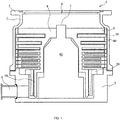
- FIG. 1 is a view showing an example of a schematic configuration of a vacuum pump 1 according to the first embodiment of the present invention, which shows a cross-sectional view of the vacuum pump 1 in an axis direction thereof.
- a diametrical direction of a rotor blade is a "diameter (diametrical/radial) direction" and a direction perpendicular to the diametrical direction of the rotor blade is the "axis direction (or axial direction)”.
- a casing (outer cylinder) 2 forming a housing of the vacuum pump 1 has a generally cylindrical shape and is included in a housing of the vacuum pump 1 in conjunction with a base 3 provided in a lower portion (on the side of an outlet port 6) of the casing 2.
- a gas transfer mechanism as a structure which causes the vacuum pump 1 to perform an exhausting function is contained.
- the gas transfer mechanism includes a rotatably supported rotating body (such as rotor blades 9/rotor cylindrical portion 10) and a stator portion (such as stator blade 30/thread groove exhaust element 20) fixed to the housing.
- a control device which controls an operation of the vacuum pump 1 is connected to the vacuum pump 1 via a dedicated line.
- an inlet port 4 for introducing a gas into the vacuum pump 1 is formed.
- a radially outwardly protruding flange portion 5 is formed.
- the outlet port 6 for exhausting the gas from the vacuum pump 1 is formed.
- the rotating body includes a shaft 7 as a rotating shaft, a rotor 8 disposed on the shaft 7, the plurality of rotor blades 9 provided in the rotor 8, and the rotor cylindrical portion (skirt portion) 10 provided on the outlet port 6 side.
- Each of the rotor blades 9 is formed of a disc member in the form of a disc extending radially and perpendicularly to an axis line of the shaft 7.
- the rotor cylindrical portion 10 is formed of a cylindrical member having a cylindrical shape coaxial to a rotation axis line of the rotor 8.
- a smaller diameter portion is provided in the rotor cylindrical portion 10. Note that the smaller diameter portion will be described later.
- a motor portion for rotating the shaft 7 at a high speed is provided and enclosed in a stator column 80.
- a radial magnetic bearing device for supporting the shaft 7 in a radial direction in non-contact relation is also provided to be closer to the inlet port 4 and the outlet port 6 than the motor portion of the shaft 7.
- an axial magnetic bearing device for supporting the shaft 7 in the axis direction (axial direction) in non-contact relation is provided.
- stator portion On an inner peripheral side of the housing (casing 2), a stator portion is formed.
- the stator portion includes stator blades 30 and blades each inclined at a predetermined angle from a plane perpendicular to the axis line of the shaft 7 and extending from an inner peripheral surface of the casing 2 toward the shaft 7.
- the stator blades 30 are spaced apart from each other by stator blade spacers 40 each having a cylindrical shape and are fixed thereby.
- the rotor blades 9 and the stator blades 30 are alternately disposed and formed in a plurality of pairs in the axis direction.
- an arbitrary number of rotor components and an arbitrary number of stator components can be provided as necessary.
- a thread groove exhaust element 20 (thread-groove exhaust mechanism) is disposed on the outlet port 6 side.
- a thread groove (helical groove) is formed in a surface of the thread groove exhaust element 20 opposed to the rotor cylindrical portion 10.
- the surface (i.e., inner peripheral surface parallel with the axis line of the vacuum pump 1) of the thread groove exhaust element 20 opposed to the rotor cylindrical portion 10 faces an outer peripheral surface of the rotor cylindrical portion 10 with a predetermined clearance being interposed therebetween.
- the thread groove exhaust element 20 is configured such that, when the rotor cylindrical portion 10 rotates at a high speed, a gas compressed by the vacuum pump 1 is transmitted toward the outlet port 6, while being guided by the tread groove with the rotation of the rotor cylindrical portion 10.
- the thread groove serves as a flow path which transports the gas.
- the surface of the thread groove exhaust element 20 opposed to the rotor cylindrical portion 10 and the rotor cylindrical portion 10 are opposed to each other with the predetermined clearance being interposed therebetween to form a gas transfer mechanism which transfers the gas using the thread groove formed in the inner peripheral surface of the thread groove exhaust element 20 extending in the axis direction.
- the clearance is preferably minimized in size.
- a direction of the helical groove formed in the thread groove exhaust element 20 corresponds to a direction extending toward the outlet port 6 when the gas is transported in a direction of rotation of the rotor 8 in the helical groove.
- the helical groove is designed such that a depth thereof decreases with approach to the outlet port 6 and that the gas transported in the helical groove is more tightly compressed with approach to the outlet port 6.
- the configuration described above allows the vacuum pump 1 to perform a vacuum exhaust process in a vacuum chamber (not shown) disposed in the vacuum pump 1.
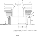
- FIG. 2 is a view for illustrating an opposed portion 10t, an extending portion 11, and a smaller diameter portion 11a in the rotor cylindrical portion 10.
- FIGS. 3A, 3B, and 3C are enlarged views of the opposed portion 10t and the extending portion 11 in the rotor cylindrical portion 10.
- the rotor cylindrical portion 10 has the opposed portion 10t opposed to the thread groove exhaust element 20 in the axis direction with a predetermined gap being interposed therebetween, the extending portion 11 extending to be closer to the outlet port 6 than the thread groove exhaust element 20, and the smaller diameter portion 11a.
- r represents an inner diameter of the opposed portion 10t of the rotor cylindrical portion 10 and Rt represents an outer diameter thereof. Also, in the description given in the present embodiment, it is assumed that Rs represents an outer diameter of a lowermost end portion (the outlet port 6 side) of the smaller diameter portion 11a and m represents a gradually varying outer diameter of the smaller diameter portion 11a. Note that the present embodiment uses the term "gradually varying outer diameter” to mean “outer diameter which gradually varies”.
- the rotor cylindrical portion 10 included in the vacuum pump 1 has the extending portion 11 extending to be closer to the outlet port 6 than the thread groove exhaust element 20.
- the smaller diameter portion 11a having the gradually varying outer diameter m (r ⁇ m ⁇ Rt) smaller than the outer diameter Rt of the portion (opposed portion 10t) of the rotor cylindrical portion 10 which is other than the extending portion 11 is formed.
- the gradually varying outer diameter m has a value decreasing with distance from the inlet port 4 toward the outlet port 6.
- the rotor cylindrical portion 10 has a portion (smaller diameter portion 11a) having a gradient at a predetermined angle ⁇ a ( FIG. 3A ) in a radially outer part of the extending portion 11.
- the gradient can be configured by, e.g., designing the extending portion 11 such that the radially outer part thereof has a tapered shape or by chamfering the radially outer part of the extending portion 11.
- the predetermined angle ⁇ a indicates an angle formed between an extension line L of a radially outer surface of the opposed portion 10t of the rotor cylindrical portion 10 and an extension line n of the gradually varying outer diameter m.
- the rotor cylindrical portion 10 is configured such that a starting point (point of origin) of the extending portion 11 coincides with a starting point of the smaller diameter portion 11a, but the configuration of the rotor cylindrical portion 10 is not limited thereto.
- the rotor cylindrical portion 10 may also be configured such that the extending portion 11 extending from the opposed portion 10t has an inlet port 4-side portion having the outer diameter Rt equal to the outer diameter of the opposed portion 10t, and the smaller diameter portion 11a having the gradually varying outer diameter m and decreasing in diameter is provided continuously to the extending portion 11.
- the rotor cylindrical portion 10 may be configured appropriately such that the smaller diameter portion 11a is formed at least in a portion of the extending portion 11 (see a configuration of a rotor cylindrical portion 100 in FIG. 4 described later).
- the rotor cylindrical portion 10 is configured such that the outer diameter Rs of a lowermost end portion (the outlet port 6 side) of the extending portion 11 coincides with a value of the gradually varying outer diameter m of the lowermost end portion (the outlet port 6 side) of the smaller diameter portion 11a.
- the configuration of the rotor cylindrical portion 10 is not limited thereto.
- the rotor cylindrical portion 10 may also be configured such that the value of the gradually varying outer diameter m of the lowermost end portion of the smaller diameter portion 11a coincides with a value of an inner diameter r of the opposed portion 10t.
- FIGS. 3B and 3C are views for illustrating modifications of the smaller diameter portion 11a ( FIG. 3A ).
- FIG. 3B shows a smaller diameter portion 11b according to a first modification
- FIG. 3C shows a smaller diameter portion 11c according to a second modification.
- the smaller diameter portion may also have a configuration similar to that of the smaller diameter portion 11b having an angle ⁇ b larger than the predetermined angle (gradient) ⁇ a of the smaller diameter portion 11a described above.
- the smaller diameter portion may also have a configuration similar to that of the smaller diameter portion 11c in which the whole smaller diameter portion has the same outer diameter, not a configuration having the gradually varying outer diameter m as the outer diameter.
- the smaller diameter portion 11c is configured to have, on the inlet port 4 side, a surface F (bottom surface) perpendicular to an axial direction of the vacuum pump 1 such that an angle formed between the surface F and a radially outer side surface of the smaller diameter portion 11c is a right angle (R).
- the smaller diameter portion 11c is configured such that the surface F formed in the smaller diameter portion 11c on the inlet port 4 side is at a position coincident with a position of the starting point of the extending portion 11, but the configuration of the smaller diameter portion 11c is not limited thereto.
- the smaller diameter portion 11c may also be configured such that the surface F formed in the smaller diameter portion 11c is at a position lower by about several millimeters than the position of the starting point of the extending portion 11 toward the outlet port 6.
- the smaller diameter portion 11c may be configured appropriately to be formed in at least a portion of the extending portion 11.
- FIGS. 4 and 5 are views for illustrating a stress reducing effect of the vacuum pump 1 according to the present embodiment.
- FIG. 4 shows a rotor cylindrical portion 100 including a smaller diameter portion 12 having a starting point different from the starting point of the extending portion 11 together with an enlarged cross-sectional view of a portion enclosed by a dotted-line ⁇ .
- ⁇ L represents an axial length of the extending portion 11 in the rotor cylindrical portion 100
- a length a represents an axial length of the smaller diameter portion 12 therein
- an area A represents a cross-sectional area of a portion cut away to form the smaller diameter portion 12 (cut-away area of a right-angled triangle defined by a solid diagonal line and two dotted lines).
- FIG. 5 is a table comparing stress reducing effects, in which an ordinate axis represents a length (p) of a radially inner part of the rotor cylindrical portion 100 from the inlet port 4 side thereof and an abscissa axis represents a stress value (analytical value obtained during simulation) in the radially inner part of the rotor cylindrical portion 100 of the vacuum pump 1 including the rotor cylindrical portion 100.
- a stress generated in a radially inner part of the smaller diameter portion 12 is smaller in a structure in which the cut-away area A (triangular or rectangular cut-away portion) is provided than in a structure "WITHOUT AREA A" in which the cut-away area A is not provided (i.e., neither the extending portion 11 nor the smaller diameter portion 12 is provided).
- the axial length ⁇ L of the extending portion 11 in the rotor cylindrical portion 100 need not be designed to be larger than the axial length a of the smaller diameter portion 12.
- the extending portion 11 and the smaller diameter portion 12 need not necessarily be configured to satisfy ⁇ L > a.
- the vacuum pump 1 including the rotor cylindrical portion 100 reduces the stress generated in the radially inner part of the rotor cylindrical portion 100.
- the rotor cylindrical portion 100 is used by way of example, but the same results can be obtained even when the rotor cylindrical portion 10 is used.
- the gradient of the smaller diameter portion 12 is formed of a linear shape in a cross section, but the shape of the gradient is not limited thereto.
- a configuration may also be adopted in which the gradient of the smaller diameter portion 12 is formed of a curved shape in a cross portion.
- the present embodiment can reduce a stress imposed on the radially inner part of each of the smaller diameter portions (11a, 11b, 11c, and 12) of the rotor cylindrical portion 10 (100) which affects a creep lifetime without reducing the rotation speed of the rotating body including the rotor cylindrical portion 10 (100).
- this configuration can increase the rotation speed of a rotor portion including the rotor cylindrical portion 10 (100), it is possible to improve the exhaust performance of the vacuum pump 1.
Landscapes
- Engineering & Computer Science (AREA)
- Mechanical Engineering (AREA)
- General Engineering & Computer Science (AREA)
- Non-Positive Displacement Air Blowers (AREA)
- Applications Or Details Of Rotary Compressors (AREA)
- Rotary Pumps (AREA)
Abstract
Description
- The present invention relates to a vacuum pump and to a rotating cylindrical body included in the vacuum pump.
- In particular, the present invention relates to a vacuum pump which reduces a stress applied to a rotating cylindrical body and to the rotating cylindrical body included in the vacuum pump.
- There is a vacuum pump for performing a vacuum exhaust process in a vacuum chamber disposed therein which includes a rotating body and a thread groove exhaust element (thread-groove exhaust mechanism/thread groove pump portion). The vacuum pump including the thread groove exhaust element has a configuration in which, under a rotor blade disposed in the rotating body, a rotating cylindrical body (rotor cylindrical portion) having no rotor blade is provided to compress a gas in the thread groove exhaust element outside the rotor blade.
- In a general vacuum pump including such a vacuum pump in which a rotor cylindrical portion is provided, a centrifugal force may cause a stress in a radially inner part of the rotor cylindrical portion, and the stress may exceed a design reference value.
-
FIG. 6 is a view for illustrating aconventional vacuum pump 1000. - As shown in
FIG. 6 , in theconventional vacuum pump 1000, a rotorcylindrical portion 1001 is disposed to be opposed to a threadgroove exhaust element 20 via a gap (clearance) in an axial direction. When a stress is generated in the rotorcylindrical portion 1001, a creep phenomenon occurs in which the rotorcylindrical portion 1001 that has moved at a high temperature for a long period is gradually deformed/expanded. - In terms of maintenance cost, a creep lifetime which is a period until the clearance between the thread
groove exhaust element 20 and the rotorcylindrical portion 1001 is reduced in size by a prescribed amount due to the creep phenomenon is preferably maximized. - Japanese Patent Application Publication No.
H10-246197 - Besides adopting such a configuration as adopted in Japanese Patent Application Publication No.
H10-246197 - However, when the rotation speed of the rotating body is reduced, exhaust performance is deteriorated.
- An object of the present invention is to provide a vacuum pump capable of reducing a stress without reducing the rotation speed of a rotating cylindrical body (rotating body), and the rotating cylindrical body included in the pump.
- The present invention in a first aspect provides a vacuum pump including a housing in which an inlet port and an outlet port are formed, a thread-groove exhaust mechanism which is fixed to the housing and has a thread groove, a rotating shaft which is rotatably supported and is enclosed in the housing, and a rotating cylindrical body which is disposed on the rotating shaft and includes an opposed portion opposed to the thread-groove exhaust mechanism via a gap and an extending portion extending downstream of the thread-groove exhaust mechanism, the extending portion including a smaller diameter portion having an outer diameter smaller than an outer diameter of the opposed portion.
- The present invention in a second aspect provides the vacuum pump in the first aspect in which the smaller diameter portion includes, on a radially outer part thereof, a bottom surface perpendicular to an axial direction of the rotating shaft, and an angle formed between the bottom surface and a radially outer surface of the smaller diameter portion is a right angle.
- The present invention in a third aspect provides the vacuum pump in the second aspect in which a position of the bottom surface of the smaller diameter portion coincides with a position of a starting point of the extending portion.
- The present invention in a fourth aspect provides the vacuum pump in the first or second aspect in which the smaller-diameter portion is formed by providing a gradient in at least a portion of the extending portion located between a starting point and a terminal point thereof.
- The present invention in a fifth aspect provides the vacuum pump in the fourth aspect in which a starting point of the gradient of the smaller diameter portion coincides with the starting point of the extending portion.
- The present invention in a sixth aspect provides a rotating cylindrical body included in the vacuum pump according to any one of the first to fifth aspects.
- According to the present invention, it is possible to reduce a stress in a portion of the rotating cylindrical body which affects a creep lifetime without reducing the rotation speed. As a result, exhaust performance can be retained or improved compared to that in a configuration designed to reduce a stress by reducing the rotation speed.
-
-
FIG. 1 is a view showing an example of a schematic configuration of a vacuum pump according to an embodiment of the present invention; -
FIG. 2 is a view for illustrating a rotor cylindrical portion according to the embodiment of the present invention; -
FIGS. 3A, 3B, and 3C are enlarged views for illustrating the rotor cylindrical portion according to the embodiment of the present invention; -
FIG. 4 is a view for illustrating a stress reducing effect of the vacuum pump according to the embodiment of the present invention; -
FIG. 5 is a view for illustrating the stress reducing effect of the vacuum pump according to the embodiment of the present invention; and -
FIG. 6 is a view for illustrating a related art technique. - In a vacuum pump according to an embodiment of the present invention, in an outlet port-side lower portion of a rotor cylindrical portion (rotating cylindrical body) included in the vacuum pump, a smaller diameter portion (tapered/chamfered portion) having an outer diameter smaller than that of an inlet port-side portion of the rotor cylindrical portion is provided.
- More specifically, a lowermost end portion (outlet port-side end portion) of the rotor cylindrical portion is designed longer than a thread groove exhaust element to provide an extending portion. In the extending portion of the rotor cylindrical portion, the smaller diameter portion having the outer diameter smaller than that of the inlet port-side portion (opposed portion) of the rotor cylindrical portion which is opposed to the thread groove exhaust element is provided.
- In the rotor cylindrical portion, a stress generated in a radially inner part during rotation thereof is smaller as an outer diameter thereof is smaller. Accordingly, a configuration having the smaller diameter portion described above can reduce a stress generated in the radially inner part of the rotor cylindrical portion without reducing the rotation speed of a rotating body (such as the rotor cylindrical portion).
- The following will describe the preferred embodiment of the present invention in detail with reference to
FIGS. 1 to 5 . -
FIG. 1 is a view showing an example of a schematic configuration of avacuum pump 1 according to the first embodiment of the present invention, which shows a cross-sectional view of thevacuum pump 1 in an axis direction thereof. - Note that, in the embodiment of the present invention, for the sake of convenience, a description will be given on the assumption that a diametrical direction of a rotor blade is a "diameter (diametrical/radial) direction" and a direction perpendicular to the diametrical direction of the rotor blade is the "axis direction (or axial direction)".
- A casing (outer cylinder) 2 forming a housing of the
vacuum pump 1 has a generally cylindrical shape and is included in a housing of thevacuum pump 1 in conjunction with abase 3 provided in a lower portion (on the side of an outlet port 6) of thecasing 2. In the housing, a gas transfer mechanism as a structure which causes thevacuum pump 1 to perform an exhausting function is contained. - In the present embodiment, the gas transfer mechanism includes a rotatably supported rotating body (such as
rotor blades 9/rotor cylindrical portion 10) and a stator portion (such asstator blade 30/thread groove exhaust element 20) fixed to the housing. - In addition, although not shown in the figure, outside the housing of the
vacuum pump 1, a control device which controls an operation of thevacuum pump 1 is connected to thevacuum pump 1 via a dedicated line. - In an end portion of the
casing 2, aninlet port 4 for introducing a gas into thevacuum pump 1 is formed. Around an inlet port 4-side end surface of thecasing 2, a radially outwardly protrudingflange portion 5 is formed. - In the
base 3, theoutlet port 6 for exhausting the gas from thevacuum pump 1 is formed. - The rotating body includes a
shaft 7 as a rotating shaft, arotor 8 disposed on theshaft 7, the plurality ofrotor blades 9 provided in therotor 8, and the rotor cylindrical portion (skirt portion) 10 provided on theoutlet port 6 side. - Each of the
rotor blades 9 is formed of a disc member in the form of a disc extending radially and perpendicularly to an axis line of theshaft 7. - The rotor
cylindrical portion 10 is formed of a cylindrical member having a cylindrical shape coaxial to a rotation axis line of therotor 8. In the present embodiment, a smaller diameter portion is provided in the rotorcylindrical portion 10. Note that the smaller diameter portion will be described later. - At about a middle of the
shaft 7 in the axis direction, a motor portion for rotating theshaft 7 at a high speed is provided and enclosed in astator column 80. - In the
stator column 80, a radial magnetic bearing device for supporting theshaft 7 in a radial direction in non-contact relation is also provided to be closer to theinlet port 4 and theoutlet port 6 than the motor portion of theshaft 7. At a lower end of theshaft 7, an axial magnetic bearing device for supporting theshaft 7 in the axis direction (axial direction) in non-contact relation is provided. - On an inner peripheral side of the housing (casing 2), a stator portion is formed. The stator portion includes
stator blades 30 and blades each inclined at a predetermined angle from a plane perpendicular to the axis line of theshaft 7 and extending from an inner peripheral surface of thecasing 2 toward theshaft 7. Thestator blades 30 are spaced apart from each other bystator blade spacers 40 each having a cylindrical shape and are fixed thereby. - Note that the
rotor blades 9 and thestator blades 30 are alternately disposed and formed in a plurality of pairs in the axis direction. To provide exhaust performance required of thevacuum pump 1, an arbitrary number of rotor components and an arbitrary number of stator components can be provided as necessary. - In the
vacuum pump 1 according to the present embodiment, a thread groove exhaust element 20 (thread-groove exhaust mechanism) is disposed on theoutlet port 6 side. - In a surface of the thread
groove exhaust element 20 opposed to the rotorcylindrical portion 10, a thread groove (helical groove) is formed. - The surface (i.e., inner peripheral surface parallel with the axis line of the vacuum pump 1) of the thread
groove exhaust element 20 opposed to the rotorcylindrical portion 10 faces an outer peripheral surface of the rotorcylindrical portion 10 with a predetermined clearance being interposed therebetween. The threadgroove exhaust element 20 is configured such that, when the rotorcylindrical portion 10 rotates at a high speed, a gas compressed by thevacuum pump 1 is transmitted toward theoutlet port 6, while being guided by the tread groove with the rotation of the rotorcylindrical portion 10. In other words, the thread groove serves as a flow path which transports the gas. - Thus, the surface of the thread
groove exhaust element 20 opposed to the rotorcylindrical portion 10 and the rotorcylindrical portion 10 are opposed to each other with the predetermined clearance being interposed therebetween to form a gas transfer mechanism which transfers the gas using the thread groove formed in the inner peripheral surface of the threadgroove exhaust element 20 extending in the axis direction. - Note that, to reduce a force which causes the gas to flow back toward the
inlet port 4, the clearance is preferably minimized in size. - A direction of the helical groove formed in the thread
groove exhaust element 20 corresponds to a direction extending toward theoutlet port 6 when the gas is transported in a direction of rotation of therotor 8 in the helical groove. - The helical groove is designed such that a depth thereof decreases with approach to the
outlet port 6 and that the gas transported in the helical groove is more tightly compressed with approach to theoutlet port 6. - The configuration described above allows the
vacuum pump 1 to perform a vacuum exhaust process in a vacuum chamber (not shown) disposed in thevacuum pump 1. - A detailed description will be given of the rotor
cylindrical portion 10 described above usingFIG. 2 andFIGS. 3A to 3C . -
FIG. 2 is a view for illustrating an opposedportion 10t, an extendingportion 11, and asmaller diameter portion 11a in the rotorcylindrical portion 10. -
FIGS. 3A, 3B, and 3C are enlarged views of the opposedportion 10t and the extendingportion 11 in the rotorcylindrical portion 10. - As shown in
FIGS. 2 and3A , the rotorcylindrical portion 10 has the opposedportion 10t opposed to the threadgroove exhaust element 20 in the axis direction with a predetermined gap being interposed therebetween, the extendingportion 11 extending to be closer to theoutlet port 6 than the threadgroove exhaust element 20, and thesmaller diameter portion 11a. - In the description given in the present embodiment, it is assumed that r represents an inner diameter of the opposed
portion 10t of the rotorcylindrical portion 10 and Rt represents an outer diameter thereof. Also, in the description given in the present embodiment, it is assumed that Rs represents an outer diameter of a lowermost end portion (theoutlet port 6 side) of thesmaller diameter portion 11a and m represents a gradually varying outer diameter of thesmaller diameter portion 11a. Note that the present embodiment uses the term "gradually varying outer diameter" to mean "outer diameter which gradually varies". - The rotor
cylindrical portion 10 included in thevacuum pump 1 according to the present embodiment has the extendingportion 11 extending to be closer to theoutlet port 6 than the threadgroove exhaust element 20. In the extendingportion 11, thesmaller diameter portion 11a having the gradually varying outer diameter m (r < m < Rt) smaller than the outer diameter Rt of the portion (opposedportion 10t) of the rotorcylindrical portion 10 which is other than the extendingportion 11 is formed. The gradually varying outer diameter m has a value decreasing with distance from theinlet port 4 toward theoutlet port 6. - In other words, the rotor
cylindrical portion 10 according to the present embodiment has a portion (smaller diameter portion 11a) having a gradient at a predetermined angle θa (FIG. 3A ) in a radially outer part of the extendingportion 11. The gradient can be configured by, e.g., designing the extendingportion 11 such that the radially outer part thereof has a tapered shape or by chamfering the radially outer part of the extendingportion 11. - Note that, in the present embodiment, the predetermined angle θa indicates an angle formed between an extension line L of a radially outer surface of the opposed
portion 10t of the rotorcylindrical portion 10 and an extension line n of the gradually varying outer diameter m. - In the present embodiment, the rotor
cylindrical portion 10 is configured such that a starting point (point of origin) of the extendingportion 11 coincides with a starting point of thesmaller diameter portion 11a, but the configuration of the rotorcylindrical portion 10 is not limited thereto. Specifically, the rotorcylindrical portion 10 may also be configured such that the extendingportion 11 extending from the opposedportion 10t has an inlet port 4-side portion having the outer diameter Rt equal to the outer diameter of the opposedportion 10t, and thesmaller diameter portion 11a having the gradually varying outer diameter m and decreasing in diameter is provided continuously to the extendingportion 11. In other words, the rotorcylindrical portion 10 may be configured appropriately such that thesmaller diameter portion 11a is formed at least in a portion of the extending portion 11 (see a configuration of a rotorcylindrical portion 100 inFIG. 4 described later). - Also, in the present embodiment, the rotor
cylindrical portion 10 is configured such that the outer diameter Rs of a lowermost end portion (theoutlet port 6 side) of the extendingportion 11 coincides with a value of the gradually varying outer diameter m of the lowermost end portion (theoutlet port 6 side) of thesmaller diameter portion 11a. However, the configuration of the rotorcylindrical portion 10 is not limited thereto. Specifically, the rotorcylindrical portion 10 may also be configured such that the value of the gradually varying outer diameter m of the lowermost end portion of thesmaller diameter portion 11a coincides with a value of an inner diameter r of the opposedportion 10t. -
FIGS. 3B and 3C are views for illustrating modifications of thesmaller diameter portion 11a (FIG. 3A ). -
FIG. 3B shows a smaller diameter portion 11b according to a first modification, whileFIG. 3C shows asmaller diameter portion 11c according to a second modification. - As shown in
FIG. 3B , the smaller diameter portion may also have a configuration similar to that of the smaller diameter portion 11b having an angle θb larger than the predetermined angle (gradient) θa of thesmaller diameter portion 11a described above. - Alternatively, as shown in
FIG. 3C , the smaller diameter portion may also have a configuration similar to that of thesmaller diameter portion 11c in which the whole smaller diameter portion has the same outer diameter, not a configuration having the gradually varying outer diameter m as the outer diameter. - Specifically, the
smaller diameter portion 11c is configured to have, on theinlet port 4 side, a surface F (bottom surface) perpendicular to an axial direction of thevacuum pump 1 such that an angle formed between the surface F and a radially outer side surface of thesmaller diameter portion 11c is a right angle (R). In this case, the predetermined angle θc described above satisfies θc = 90 degrees. - Note that, in
FIG. 3C , thesmaller diameter portion 11c is configured such that the surface F formed in thesmaller diameter portion 11c on theinlet port 4 side is at a position coincident with a position of the starting point of the extendingportion 11, but the configuration of thesmaller diameter portion 11c is not limited thereto. Thesmaller diameter portion 11c may also be configured such that the surface F formed in thesmaller diameter portion 11c is at a position lower by about several millimeters than the position of the starting point of the extendingportion 11 toward theoutlet port 6. In other words, thesmaller diameter portion 11c may be configured appropriately to be formed in at least a portion of the extendingportion 11. -
FIGS. 4 and5 are views for illustrating a stress reducing effect of thevacuum pump 1 according to the present embodiment. -
FIG. 4 shows a rotorcylindrical portion 100 including asmaller diameter portion 12 having a starting point different from the starting point of the extendingportion 11 together with an enlarged cross-sectional view of a portion enclosed by a dotted-line α. - In
FIG. 4 , ΔL represents an axial length of the extendingportion 11 in the rotorcylindrical portion 100, a length a represents an axial length of thesmaller diameter portion 12 therein, and an area A represents a cross-sectional area of a portion cut away to form the smaller diameter portion 12 (cut-away area of a right-angled triangle defined by a solid diagonal line and two dotted lines). -
FIG. 5 is a table comparing stress reducing effects, in which an ordinate axis represents a length (p) of a radially inner part of the rotorcylindrical portion 100 from theinlet port 4 side thereof and an abscissa axis represents a stress value (analytical value obtained during simulation) in the radially inner part of the rotorcylindrical portion 100 of thevacuum pump 1 including the rotorcylindrical portion 100. - As shown in
FIG. 5 , it can be seen from the analytical values that a stress generated in a radially inner part of thesmaller diameter portion 12 is smaller in a structure in which the cut-away area A (triangular or rectangular cut-away portion) is provided than in a structure "WITHOUT AREA A" in which the cut-away area A is not provided (i.e., neither the extendingportion 11 nor thesmaller diameter portion 12 is provided). - It can also be seen from the result of analysis shown in
FIG. 5 that, when the cut-away areas A have the same value, a configuration which satisfies "a > m" can most significantly reduce the stress. - Accordingly, unless particularly restricted, the axial length ΔL of the extending
portion 11 in the rotorcylindrical portion 100 need not be designed to be larger than the axial length a of thesmaller diameter portion 12. In other words, the extendingportion 11 and thesmaller diameter portion 12 need not necessarily be configured to satisfy ΔL > a. - Thus, it can be seen that, using the structures of the extending
portion 11 and thesmaller diameter portion 12, thevacuum pump 1 including the rotorcylindrical portion 100 reduces the stress generated in the radially inner part of the rotorcylindrical portion 100. - Note that, in
FIGS. 4 and5 , the rotorcylindrical portion 100 is used by way of example, but the same results can be obtained even when the rotorcylindrical portion 10 is used. - Note that, in the configuration adopted in the present embodiment, the gradient of the
smaller diameter portion 12 is formed of a linear shape in a cross section, but the shape of the gradient is not limited thereto. For example, although not shown in the figure, a configuration may also be adopted in which the gradient of thesmaller diameter portion 12 is formed of a curved shape in a cross portion. - By adopting the configurations described above, the present embodiment can reduce a stress imposed on the radially inner part of each of the smaller diameter portions (11a, 11b, 11c, and 12) of the rotor cylindrical portion 10 (100) which affects a creep lifetime without reducing the rotation speed of the rotating body including the rotor cylindrical portion 10 (100).
- In addition, since it is possible to prevent a creep phenomenon without reducing the rotation speed, it is possible to prevent deterioration of the exhaust performance of the
vacuum pump 1 due to a reduction in the rotation speed. - Alternatively, since this configuration can increase the rotation speed of a rotor portion including the rotor cylindrical portion 10 (100), it is possible to improve the exhaust performance of the
vacuum pump 1. - Note that the embodiment of the present invention and the individual modifications thereof may also be configured to be combined with each other as necessary.
- Various modifications can be made to the present invention without departing from the spirit of the present invention. It should be clearly understood that the present invention is intended to encompass such modifications.
-
- 1
- Vacuum pump
- 2
- Casing (outer cylinder)
- 3
- Base
- 4
- Inlet port
- 5
- Flange portion
- 6
- Outlet port
- 7
- Shaft
- 8
- Rotor
- 9
- Rotor blade
- 10
- Rotor cylindrical portion
- 10t
- Opposed portion
- 11
- Extending portion
- 11a
- Smaller diameter portion
- 11b
- Smaller diameter portion
- 11c
- Smaller diameter portion
- 12
- Smaller diameter portion
- 20
- Thread groove exhaust element
- 30
- Stator blade
- 40
- Stator blade spacer
- 80
- Stator column
- 100
- Rotor cylindrical portion
- 1000
- Conventional vacuum pump
- 1001
- Rotor cylindrical portion
Claims (6)
- A vacuum pump comprising:a housing in which an inlet port and an outlet port are formed;a thread-groove exhaust mechanism which is fixed to the housing and has a thread groove;a rotating shaft which is rotatably supported and is enclosed in the housing; anda rotating cylindrical body which is disposed on the rotating shaft and includes an opposed portion opposed to the thread-groove exhaust mechanism via a gap and an extending portion extending downstream of the thread-groove exhaust mechanism, the extending portion including a smaller diameter portion having an outer diameter smaller than an outer diameter of the opposed portion.
- The vacuum pump according to claim 1, whereinthe smaller diameter portion includes, on a radially outer part thereof, a bottom surface perpendicular to an axial direction of the rotating shaft, andan angle formed between the bottom surface and a radially outer surface of the smaller diameter portion is a right angle.
- The vacuum pump according to claim 2, wherein
a position of the bottom surface of the smaller diameter portion coincides with a position of a starting point of the extending portion. - The vacuum pump according to claim 1 or 2, wherein
the smaller-diameter portion is formed by providing a gradient in at least a portion of the extending portion located between a starting point and a terminal point thereof. - The vacuum pump according to claim 4, wherein
a starting point of the gradient of the smaller diameter portion coincides with the starting point of the extending portion. - A rotating cylindrical body included in the vacuum pump according to any one of claims 1 to 5.
Applications Claiming Priority (2)
| Application Number | Priority Date | Filing Date | Title |
|---|---|---|---|
| JP2016168083A JP7015106B2 (en) | 2016-08-30 | 2016-08-30 | Vacuum pumps and rotating cylinders included in vacuum pumps |
| PCT/JP2017/028865 WO2018043072A1 (en) | 2016-08-30 | 2017-08-09 | Vacuum pump and rotary cylindrical body installed in vacuum pump |
Publications (3)
| Publication Number | Publication Date |
|---|---|
| EP3524821A1 true EP3524821A1 (en) | 2019-08-14 |
| EP3524821A4 EP3524821A4 (en) | 2020-07-22 |
| EP3524821B1 EP3524821B1 (en) | 2025-10-01 |
Family
ID=61300606
Family Applications (1)
| Application Number | Title | Priority Date | Filing Date |
|---|---|---|---|
| EP17846081.2A Active EP3524821B1 (en) | 2016-08-30 | 2017-08-09 | Vacuum pump and rotary cylindrical body installed in vacuum pump |
Country Status (6)
| Country | Link |
|---|---|
| US (1) | US11078925B2 (en) |
| EP (1) | EP3524821B1 (en) |
| JP (1) | JP7015106B2 (en) |
| KR (1) | KR102418911B1 (en) |
| CN (1) | CN109563841B (en) |
| WO (1) | WO2018043072A1 (en) |
Families Citing this family (3)
| Publication number | Priority date | Publication date | Assignee | Title |
|---|---|---|---|---|
| JP7668613B2 (en) * | 2019-02-04 | 2025-04-25 | エドワーズ株式会社 | Vacuum pump |
| JP7546412B2 (en) | 2020-08-21 | 2024-09-06 | エドワーズ株式会社 | Vacuum pumps, stators and spacers |
| JP2022062902A (en) * | 2020-10-09 | 2022-04-21 | エドワーズ株式会社 | Vacuum pump and rotary cylindrical body included in the same |
Family Cites Families (11)
| Publication number | Priority date | Publication date | Assignee | Title |
|---|---|---|---|---|
| JPS5286576A (en) * | 1976-01-14 | 1977-07-19 | Hitachi Ltd | Particle pump for gas centrifugation |
| NL8303927A (en) * | 1983-11-16 | 1985-06-17 | Ultra Centrifuge Nederland Nv | HIGH VACUUM MOLECULAR PUMP. |
| JPH0759955B2 (en) * | 1988-07-15 | 1995-06-28 | ダイキン工業株式会社 | Vacuum pump |
| FR2634829B1 (en) * | 1988-07-27 | 1990-09-14 | Cit Alcatel | VACUUM PUMP |
| JPH03222895A (en) * | 1990-01-26 | 1991-10-01 | Hitachi Koki Co Ltd | Thread-grooved vacuum pump |
| JPH10246197A (en) | 1997-03-05 | 1998-09-14 | Ebara Corp | Turbo-molecular pump |
| JP3518343B2 (en) * | 1998-06-19 | 2004-04-12 | 株式会社島津製作所 | Turbo vacuum pump |
| US20080131288A1 (en) * | 2006-11-30 | 2008-06-05 | Shimadzu Corporation | Vacuum pump |
| EP2472119B1 (en) * | 2009-08-26 | 2016-10-12 | Shimadzu Corporation | Turbo-molecular pump and method of manufacturing rotor |
| JP5878876B2 (en) * | 2010-12-10 | 2016-03-08 | エドワーズ株式会社 | Vacuum pump |
| JP6390098B2 (en) * | 2013-12-25 | 2018-09-19 | 株式会社島津製作所 | Vacuum pump |
-
2016
- 2016-08-30 JP JP2016168083A patent/JP7015106B2/en active Active
-
2017
- 2017-08-09 KR KR1020187034339A patent/KR102418911B1/en active Active
- 2017-08-09 EP EP17846081.2A patent/EP3524821B1/en active Active
- 2017-08-09 US US16/327,154 patent/US11078925B2/en active Active
- 2017-08-09 CN CN201780049929.5A patent/CN109563841B/en active Active
- 2017-08-09 WO PCT/JP2017/028865 patent/WO2018043072A1/en not_active Ceased
Also Published As
| Publication number | Publication date |
|---|---|
| WO2018043072A1 (en) | 2018-03-08 |
| US11078925B2 (en) | 2021-08-03 |
| JP2018035718A (en) | 2018-03-08 |
| EP3524821B1 (en) | 2025-10-01 |
| US20190195238A1 (en) | 2019-06-27 |
| CN109563841B (en) | 2024-07-30 |
| JP7015106B2 (en) | 2022-02-02 |
| KR20190040131A (en) | 2019-04-17 |
| EP3524821A4 (en) | 2020-07-22 |
| KR102418911B1 (en) | 2022-07-08 |
| CN109563841A (en) | 2019-04-02 |
Similar Documents
| Publication | Publication Date | Title |
|---|---|---|
| EP3524822B1 (en) | Vacuum pump, helical plate for vacuum pump, spacer, and rotating cylindrical body | |
| EP3388681B1 (en) | Linked-type screw groove spacer, and vacuum pump | |
| EP3524821B1 (en) | Vacuum pump and rotary cylindrical body installed in vacuum pump | |
| US11009028B2 (en) | Vacuum pump and stator disk to be installed in vacuum pump | |
| CN106415020A (en) | Vacuum pump | |
| CN108930656B (en) | Vacuum exhaust device, vacuum pump and vacuum valve | |
| EP3048306B1 (en) | Vacuum pump with deformable stator component | |
| JP4749054B2 (en) | Turbomolecular pump and method of assembling turbomolecular pump | |
| EP3581801B1 (en) | Vacuum pump and imbalance correction method | |
| JP2005016525A (en) | Variable mounting angle blade guiding device | |
| CN107208650B (en) | Adapters and Vacuum Pumps | |
| US11898565B2 (en) | Vacuum pump and linked-type thread groove spacer | |
| US10801507B2 (en) | Vacuum pump, spiral plate provided in vacuum pump, rotating cylinder and method for manufacturing spiral plate | |
| JP5276321B2 (en) | Turbo molecular pump | |
| JP4103709B2 (en) | Screw compressor | |
| CN114026335B (en) | Vacuum pump | |
| US10385873B2 (en) | Fan | |
| JP2008280977A (en) | Turbo molecular pump |
Legal Events
| Date | Code | Title | Description |
|---|---|---|---|
| STAA | Information on the status of an ep patent application or granted ep patent |
Free format text: STATUS: THE INTERNATIONAL PUBLICATION HAS BEEN MADE |
|
| PUAI | Public reference made under article 153(3) epc to a published international application that has entered the european phase |
Free format text: ORIGINAL CODE: 0009012 |
|
| STAA | Information on the status of an ep patent application or granted ep patent |
Free format text: STATUS: REQUEST FOR EXAMINATION WAS MADE |
|
| 17P | Request for examination filed |
Effective date: 20190206 |
|
| AK | Designated contracting states |
Kind code of ref document: A1 Designated state(s): AL AT BE BG CH CY CZ DE DK EE ES FI FR GB GR HR HU IE IS IT LI LT LU LV MC MK MT NL NO PL PT RO RS SE SI SK SM TR |
|
| AX | Request for extension of the european patent |
Extension state: BA ME |
|
| DAV | Request for validation of the european patent (deleted) | ||
| DAX | Request for extension of the european patent (deleted) | ||
| A4 | Supplementary search report drawn up and despatched |
Effective date: 20200619 |
|
| RIC1 | Information provided on ipc code assigned before grant |
Ipc: F04D 19/04 20060101AFI20200615BHEP Ipc: F04D 29/32 20060101ALI20200615BHEP |
|
| STAA | Information on the status of an ep patent application or granted ep patent |
Free format text: STATUS: EXAMINATION IS IN PROGRESS |
|
| 17Q | First examination report despatched |
Effective date: 20211223 |
|
| GRAP | Despatch of communication of intention to grant a patent |
Free format text: ORIGINAL CODE: EPIDOSNIGR1 |
|
| STAA | Information on the status of an ep patent application or granted ep patent |
Free format text: STATUS: GRANT OF PATENT IS INTENDED |
|
| INTG | Intention to grant announced |
Effective date: 20250407 |
|
| GRAS | Grant fee paid |
Free format text: ORIGINAL CODE: EPIDOSNIGR3 |
|
| GRAA | (expected) grant |
Free format text: ORIGINAL CODE: 0009210 |
|
| STAA | Information on the status of an ep patent application or granted ep patent |
Free format text: STATUS: THE PATENT HAS BEEN GRANTED |
|
| AK | Designated contracting states |
Kind code of ref document: B1 Designated state(s): AL AT BE BG CH CY CZ DE DK EE ES FI FR GB GR HR HU IE IS IT LI LT LU LV MC MK MT NL NO PL PT RO RS SE SI SK SM TR |
|
| REG | Reference to a national code |
Ref country code: GB Ref legal event code: FG4D Ref country code: CH Ref legal event code: F10 Free format text: ST27 STATUS EVENT CODE: U-0-0-F10-F00 (AS PROVIDED BY THE NATIONAL OFFICE) Effective date: 20251001 |
|
| REG | Reference to a national code |
Ref country code: IE Ref legal event code: FG4D |
|
| REG | Reference to a national code |
Ref country code: DE Ref legal event code: R096 Ref document number: 602017092042 Country of ref document: DE |
|
| REG | Reference to a national code |
Ref country code: NL Ref legal event code: MP Effective date: 20251001 |
|
| REG | Reference to a national code |
Ref country code: AT Ref legal event code: MK05 Ref document number: 1842745 Country of ref document: AT Kind code of ref document: T Effective date: 20251001 |
|
| PG25 | Lapsed in a contracting state [announced via postgrant information from national office to epo] |
Ref country code: NL Free format text: LAPSE BECAUSE OF FAILURE TO SUBMIT A TRANSLATION OF THE DESCRIPTION OR TO PAY THE FEE WITHIN THE PRESCRIBED TIME-LIMIT Effective date: 20251001 |
|
| PG25 | Lapsed in a contracting state [announced via postgrant information from national office to epo] |
Ref country code: ES Free format text: LAPSE BECAUSE OF FAILURE TO SUBMIT A TRANSLATION OF THE DESCRIPTION OR TO PAY THE FEE WITHIN THE PRESCRIBED TIME-LIMIT Effective date: 20251001 |
|
| REG | Reference to a national code |
Ref country code: LT Ref legal event code: MG9D |
|
| PG25 | Lapsed in a contracting state [announced via postgrant information from national office to epo] |
Ref country code: NO Free format text: LAPSE BECAUSE OF FAILURE TO SUBMIT A TRANSLATION OF THE DESCRIPTION OR TO PAY THE FEE WITHIN THE PRESCRIBED TIME-LIMIT Effective date: 20260101 |
|
| PG25 | Lapsed in a contracting state [announced via postgrant information from national office to epo] |
Ref country code: HR Free format text: LAPSE BECAUSE OF FAILURE TO SUBMIT A TRANSLATION OF THE DESCRIPTION OR TO PAY THE FEE WITHIN THE PRESCRIBED TIME-LIMIT Effective date: 20251001 Ref country code: AT Free format text: LAPSE BECAUSE OF FAILURE TO SUBMIT A TRANSLATION OF THE DESCRIPTION OR TO PAY THE FEE WITHIN THE PRESCRIBED TIME-LIMIT Effective date: 20251001 Ref country code: FI Free format text: LAPSE BECAUSE OF FAILURE TO SUBMIT A TRANSLATION OF THE DESCRIPTION OR TO PAY THE FEE WITHIN THE PRESCRIBED TIME-LIMIT Effective date: 20251001 |
|
| PG25 | Lapsed in a contracting state [announced via postgrant information from national office to epo] |
Ref country code: RS Free format text: LAPSE BECAUSE OF FAILURE TO SUBMIT A TRANSLATION OF THE DESCRIPTION OR TO PAY THE FEE WITHIN THE PRESCRIBED TIME-LIMIT Effective date: 20260101 |
|
| PG25 | Lapsed in a contracting state [announced via postgrant information from national office to epo] |
Ref country code: IS Free format text: LAPSE BECAUSE OF FAILURE TO SUBMIT A TRANSLATION OF THE DESCRIPTION OR TO PAY THE FEE WITHIN THE PRESCRIBED TIME-LIMIT Effective date: 20260201 |
|
| PG25 | Lapsed in a contracting state [announced via postgrant information from national office to epo] |
Ref country code: CZ Free format text: LAPSE BECAUSE OF FAILURE TO SUBMIT A TRANSLATION OF THE DESCRIPTION OR TO PAY THE FEE WITHIN THE PRESCRIBED TIME-LIMIT Effective date: 20251001 Ref country code: PT Free format text: LAPSE BECAUSE OF FAILURE TO SUBMIT A TRANSLATION OF THE DESCRIPTION OR TO PAY THE FEE WITHIN THE PRESCRIBED TIME-LIMIT Effective date: 20260202 |
|
| PG25 | Lapsed in a contracting state [announced via postgrant information from national office to epo] |
Ref country code: PL Free format text: LAPSE BECAUSE OF FAILURE TO SUBMIT A TRANSLATION OF THE DESCRIPTION OR TO PAY THE FEE WITHIN THE PRESCRIBED TIME-LIMIT Effective date: 20251001 |
|
| PG25 | Lapsed in a contracting state [announced via postgrant information from national office to epo] |
Ref country code: LV Free format text: LAPSE BECAUSE OF FAILURE TO SUBMIT A TRANSLATION OF THE DESCRIPTION OR TO PAY THE FEE WITHIN THE PRESCRIBED TIME-LIMIT Effective date: 20251001 |
|
| PG25 | Lapsed in a contracting state [announced via postgrant information from national office to epo] |
Ref country code: BG Free format text: LAPSE BECAUSE OF FAILURE TO SUBMIT A TRANSLATION OF THE DESCRIPTION OR TO PAY THE FEE WITHIN THE PRESCRIBED TIME-LIMIT Effective date: 20251001 |