EP3524817A1 - Scroll type fluid machine, seal member, and seal - Google Patents
Scroll type fluid machine, seal member, and seal Download PDFInfo
- Publication number
- EP3524817A1 EP3524817A1 EP17858452.0A EP17858452A EP3524817A1 EP 3524817 A1 EP3524817 A1 EP 3524817A1 EP 17858452 A EP17858452 A EP 17858452A EP 3524817 A1 EP3524817 A1 EP 3524817A1
- Authority
- EP
- European Patent Office
- Prior art keywords
- scroll
- seal member
- dustproof seal
- dustproof
- fluid machine
- Prior art date
- Legal status (The legal status is an assumption and is not a legal conclusion. Google has not performed a legal analysis and makes no representation as to the accuracy of the status listed.)
- Withdrawn
Links
Images









Classifications
-
- F—MECHANICAL ENGINEERING; LIGHTING; HEATING; WEAPONS; BLASTING
- F04—POSITIVE - DISPLACEMENT MACHINES FOR LIQUIDS; PUMPS FOR LIQUIDS OR ELASTIC FLUIDS
- F04C—ROTARY-PISTON, OR OSCILLATING-PISTON, POSITIVE-DISPLACEMENT MACHINES FOR LIQUIDS; ROTARY-PISTON, OR OSCILLATING-PISTON, POSITIVE-DISPLACEMENT PUMPS
- F04C18/00—Rotary-piston pumps specially adapted for elastic fluids
- F04C18/02—Rotary-piston pumps specially adapted for elastic fluids of arcuate-engagement type, i.e. with circular translatory movement of co-operating members, each member having the same number of teeth or tooth-equivalents
- F04C18/0207—Rotary-piston pumps specially adapted for elastic fluids of arcuate-engagement type, i.e. with circular translatory movement of co-operating members, each member having the same number of teeth or tooth-equivalents both members having co-operating elements in spiral form
- F04C18/0215—Rotary-piston pumps specially adapted for elastic fluids of arcuate-engagement type, i.e. with circular translatory movement of co-operating members, each member having the same number of teeth or tooth-equivalents both members having co-operating elements in spiral form where only one member is moving
-
- F—MECHANICAL ENGINEERING; LIGHTING; HEATING; WEAPONS; BLASTING
- F01—MACHINES OR ENGINES IN GENERAL; ENGINE PLANTS IN GENERAL; STEAM ENGINES
- F01C—ROTARY-PISTON OR OSCILLATING-PISTON MACHINES OR ENGINES
- F01C1/00—Rotary-piston machines or engines
- F01C1/02—Rotary-piston machines or engines of arcuate-engagement type, i.e. with circular translatory movement of co-operating members, each member having the same number of teeth or tooth-equivalents
- F01C1/0207—Rotary-piston machines or engines of arcuate-engagement type, i.e. with circular translatory movement of co-operating members, each member having the same number of teeth or tooth-equivalents both members having co-operating elements in spiral form
- F01C1/0246—Details concerning the involute wraps or their base, e.g. geometry
-
- F—MECHANICAL ENGINEERING; LIGHTING; HEATING; WEAPONS; BLASTING
- F01—MACHINES OR ENGINES IN GENERAL; ENGINE PLANTS IN GENERAL; STEAM ENGINES
- F01C—ROTARY-PISTON OR OSCILLATING-PISTON MACHINES OR ENGINES
- F01C19/00—Sealing arrangements in rotary-piston machines or engines
- F01C19/005—Structure and composition of sealing elements such as sealing strips, sealing rings and the like; Coating of these elements
-
- F—MECHANICAL ENGINEERING; LIGHTING; HEATING; WEAPONS; BLASTING
- F04—POSITIVE - DISPLACEMENT MACHINES FOR LIQUIDS; PUMPS FOR LIQUIDS OR ELASTIC FLUIDS
- F04C—ROTARY-PISTON, OR OSCILLATING-PISTON, POSITIVE-DISPLACEMENT MACHINES FOR LIQUIDS; ROTARY-PISTON, OR OSCILLATING-PISTON, POSITIVE-DISPLACEMENT PUMPS
- F04C15/00—Component parts, details or accessories of machines, pumps or pumping installations, not provided for in groups F04C2/00 - F04C14/00
- F04C15/0003—Sealing arrangements in rotary-piston machines or pumps
-
- F—MECHANICAL ENGINEERING; LIGHTING; HEATING; WEAPONS; BLASTING
- F04—POSITIVE - DISPLACEMENT MACHINES FOR LIQUIDS; PUMPS FOR LIQUIDS OR ELASTIC FLUIDS
- F04C—ROTARY-PISTON, OR OSCILLATING-PISTON, POSITIVE-DISPLACEMENT MACHINES FOR LIQUIDS; ROTARY-PISTON, OR OSCILLATING-PISTON, POSITIVE-DISPLACEMENT PUMPS
- F04C15/00—Component parts, details or accessories of machines, pumps or pumping installations, not provided for in groups F04C2/00 - F04C14/00
- F04C15/0003—Sealing arrangements in rotary-piston machines or pumps
- F04C15/0023—Axial sealings for working fluid
-
- F—MECHANICAL ENGINEERING; LIGHTING; HEATING; WEAPONS; BLASTING
- F04—POSITIVE - DISPLACEMENT MACHINES FOR LIQUIDS; PUMPS FOR LIQUIDS OR ELASTIC FLUIDS
- F04C—ROTARY-PISTON, OR OSCILLATING-PISTON, POSITIVE-DISPLACEMENT MACHINES FOR LIQUIDS; ROTARY-PISTON, OR OSCILLATING-PISTON, POSITIVE-DISPLACEMENT PUMPS
- F04C18/00—Rotary-piston pumps specially adapted for elastic fluids
- F04C18/02—Rotary-piston pumps specially adapted for elastic fluids of arcuate-engagement type, i.e. with circular translatory movement of co-operating members, each member having the same number of teeth or tooth-equivalents
-
- F—MECHANICAL ENGINEERING; LIGHTING; HEATING; WEAPONS; BLASTING
- F04—POSITIVE - DISPLACEMENT MACHINES FOR LIQUIDS; PUMPS FOR LIQUIDS OR ELASTIC FLUIDS
- F04C—ROTARY-PISTON, OR OSCILLATING-PISTON, POSITIVE-DISPLACEMENT MACHINES FOR LIQUIDS; ROTARY-PISTON, OR OSCILLATING-PISTON, POSITIVE-DISPLACEMENT PUMPS
- F04C27/00—Sealing arrangements in rotary-piston pumps specially adapted for elastic fluids
-
- F—MECHANICAL ENGINEERING; LIGHTING; HEATING; WEAPONS; BLASTING
- F04—POSITIVE - DISPLACEMENT MACHINES FOR LIQUIDS; PUMPS FOR LIQUIDS OR ELASTIC FLUIDS
- F04C—ROTARY-PISTON, OR OSCILLATING-PISTON, POSITIVE-DISPLACEMENT MACHINES FOR LIQUIDS; ROTARY-PISTON, OR OSCILLATING-PISTON, POSITIVE-DISPLACEMENT PUMPS
- F04C27/00—Sealing arrangements in rotary-piston pumps specially adapted for elastic fluids
- F04C27/008—Sealing arrangements in rotary-piston pumps specially adapted for elastic fluids for other than working fluid, i.e. the sealing arrangements are not between working chambers of the machine
Definitions
- the present invention relates to a scroll fluid machine excellent in durability.
- the invention also relates to a seal member and a seal.
- a scroll fluid machine having a fixed scroll and an orbiting scroll that orbits relative to the fixed scroll is known as disclosed, for example, in Japanese Patent Application Publication H.7-208353 ( JP7-208353A ).
- the scroll fluid machine has a working room formed between the fixed scroll and the orbiting scroll.
- the fixed scroll and the orbiting scroll each have a spiral wrap protruding toward the working room.
- An inlet and an outlet for communicating the working room to the outside are provided.
- fluid is compressed along a spiral flow path defined by the spiral wrap.
- the fluid is suctioned from the inlet located at an outer peripheral portion, and the compressed fluid is discharged from the outlet located at the center.
- a negative pressure is generated in the working room during operation.
- a dustproof seal is provided in the scroll fluid machine.
- the strip-shaped dustproof seal is arranged such that its both ends overlap in the radial direction to surround the working room.
- the dustproof seal arranged in this way seals between the fixed scroll and the orbiting scroll.
- the invention is made based on such findings of the inventors, and one object of the invention is to effectively prevent inflow of external fluid into the scroll fluid machine, thereby effectively suppressing deterioration of the tip seal. Another object of the invention is to provide seal and a seal member capable of effectively preventing the inflow of external fluid.
- JP7-208353A proposed to adopt a seamless and endless annular dustproof seal element.
- the dustproof seal member between the fixed scroll and the orbiting scroll becomes meandering or twisted due to thermal deformation, and such deformation causes leak.
- conventional scroll fluid machines failed to overcome such a drawback.
- the scroll fluid machine includes a first scroll and a second scroll that are movable relative to each other and are opposed to each other, and an annular dustproof seal member disposed so as to contact the first and second scrolls therebetween.
- the scroll fluid machine may include one or more of the features described below.
- a scroll fluid machine includes a first scroll and a second scroll movable relative to each other and opposed to each other, and an annular dustproof seal member disposed between and in contact with the first scroll and the second scroll and having a cut, the cut defined by two portions overlapped each other in a width direction thereof.
- a width of a portion of the dustproof seal member where the two portions overlap each other is equal to or smaller than a width of other portion of the dustproof seal member, and the two portions are movable relative to each other while they are overlapped in the width direction.
- the dustproof seal member may include, as the two portions, an inner portion and an outer portion situated on the outer side of the inner portion in the width direction, the inner portion may be tapered such that its outer side surface facing outward is inclined with respect to an outer side surface of a portion adjacent to the inner portion of the dustproof seal member, the outer portion may be tapered such that its inner side surface facing inward is inclined with respect to an inner side surface of a portion adjacent to the outer portion of the dustproof seal member, and the outer side surface of the inner portion and the inner side surface of the outer portion may contact each other.
- one of the two portions may have a recessed portion recessed in a circumferential direction of the annular dustproof seal member, and the other of the two portions may have a convex portion that protrudes in the circumferential direction and is inserted into the concave portion.
- the dustproof seal member may include, as the two portions, an inner portion and an outer portion situated on the outer side of the inner portion in the width direction
- the inner portion may include a base portion having a width smaller than a width of a portion adjacent to the inner portion of the dustproof seal member, and a wide portion situated closer to a tip of the dustproof seal member than the base portion in a longitudinal direction of the dustproof seal member and having a width larger than the base portion
- the outer portion may include a base portion having a width smaller than a width of a portion adjacent to the outer portion of the dustproof seal member, and a wide portion situated closer to the tip of the dustproof seal member than the base portion in the longitudinal direction of the dustproof seal member and having a width larger than the base portion.
- the wide portion of the inner portion may face the base portion of the outer portion in the width direction
- the wide portion of the outer portion may face the base portion of the inner portion in the width direction.
- the scroll fluid machine may further include a pressing means for pressing one of the two portions toward the other of the two portions.
- the pressing means may press the one of the two portions toward the other of the two portions in the width direction.
- the pressing means may include an elastic member.
- the pressing means may include a fluid ejection mechanism.
- a circumferential groove may be formed in one of the first scroll and the second scroll, the dustproof seal member may be disposed in the groove, and the fluid ejection mechanism may eject a fluid into the groove.
- a circumferential groove may be formed in one of the first scroll and the second scroll, the dustproof seal member may be disposed in the groove, and the dustproof seal member may include, as the two portions, an inner portion and an outer portion situated on the outer side of the inner portion in the width direction.
- the dustproof seal member may further include an inner protrusion that protrudes inward from an inner side surface of the inner portion facing the inner side, and/or an outer protrusion that protrudes outward from an outer side surface of the outer portion facing the outer side.
- the inner protrusion may taper toward the inner side, and the outer protrusion tapers toward the outer side.
- the outer protrusion may include a tip-end side surface and a base-end side surface opposed to each other in a longitudinal direction of the dustproof seal member, when observed from the direction in which the first scroll and the second scroll oppose each other, an angle of the tip-end side surface with the longitudinal direction of the dustproof seal member may be smaller than an angle of the base-end side surface with the longitudinal direction, the tip-end side surface is situated closer to a tip of the dustproof seal member in the longitudinal direction than the base-end side surface.
- the outer protrusion may include a tip-end side surface and a base-end side surface opposed to each other in the longitudinal direction of the dustproof seal member, when observed from the direction in which the first scroll and the second scroll oppose each other, an angle of the tip-end side surface with the longitudinal direction of the dustproof seal member may be smaller than an angle of the base-end side surface with the longitudinal direction, and the tip-end side surface is situated closer to a tip of the dustproof seal member in the longitudinal direction than the base-end side surface.
- a circumferential groove may be formed in one of the first scroll and the second scroll, the dustproof seal member may be disposed in the groove, and a pasty material may be filled at least between the two portions of the dustproof seal member in the groove.
- the scroll fluid machine according to the first aspect of the invention may further include a second dustproof seal member provided on the inner side or outer side of the dustproof seal member.
- a scroll fluid machine includes a first scroll and a second scroll movable relative to each other and opposed to each other, a first seal portion made of metal, having an endless annular shape, and disposed on one of the first scroll and the second scroll, and a second seal portion made of resin or rubber, having an endless annular shape, and disposed on the first seal portion so as to contact the other of the first scroll and the second scroll.
- a circumferential groove may be formed in one of the first scroll and the second scroll, and the first seal portion and the second seal portion may be disposed in the same groove so as to overlap with each other in a direction in which the first scroll and the second scroll face each other.
- the second seal portion may be a fluorine-based resin layer formed on the first seal portion.
- a width of the first seal portion in the direction in which the first scroll and the second scroll face each other may be larger than a width of the second seal portion.
- a surface at which the first seal portion and the second seal portion contact each other may be inclined with respect to a width direction in the direction in which the first scroll and the second scroll face each other.
- a scroll fluid machine includes a first scroll and a second scroll movable relative to each other and opposed to each other, and an annular dustproof seal having one or more portions contiguously overlapped in its width direction so as to be in contact with the first scroll and the second scroll.
- a length of a narrowest portion of the dustproof seal is shorter than the other portion of the dustproof seal.
- a single dustproof seal member may be provided in the narrowest portion, and two or more of the narrowest portions may be provided so as to be separated from each other in a circumferential direction of the dustproof seal.
- one of the narrowest portions may be provided in a region including one of two positions most spaced apart along the circumferential direction of the dustproof seal, and other one of the narrowest portions may be provided in a region including the other of the two positions.
- a scroll fluid machine includes a first scroll and a second scroll movable relative to each other and opposed to each other, and an annular dustproof seal disposed between and in contact with the first scroll and the second scroll.
- the annular dustproof seal includes two or more portions thereof overlap with each other in the width direction. The length of the region of the dustproof seal where the two or more portions overlap is longer than the length of the other region.
- the region in which two or more portions of the seal S overlap may be provided so as to be apart from each other in the longitudinal direction of the dustproof seal.
- one of the regions in which the two or more portions of the seal overlap may be provided in a region including one of two positions most separated along the circumferential direction of the seal, and another of the regions in which the two or more portions of the seal S overlap may be provided in a region including another of the two positions.
- a scroll fluid machine includes a first scroll and a second scroll movable relative to each other and opposed to each other, and an annular dustproof seal member disposed between and in contact with the first scroll and the second scroll and having a cut, the cut defined by two portions overlapped each other in a width direction thereof, and a pressing means for pressing one of the two portions toward the other of the two portions.
- a scroll fluid machine includes a first scroll and a second scroll movable relative to each other and opposed to each other, and an annular dustproof seal member disposed between and in contact with the first scroll and the second scroll and having a cut, the cut defined by two portions overlapped each other in a width direction thereof.
- a circumferential groove is formed in one of the first scroll and the second scroll, the dustproof seal member is disposed in the groove, and a pasty material is filled at least between the two portions of the dustproof seal member in the groove.
- a scroll fluid machine includes a first scroll and a second scroll movable relative to each other and opposed to each other, and an annular dustproof seal member disposed between and in contact with the first scroll and the second scroll and having a cut, the cut defined by two portions overlapped each other in a width direction thereof.
- a circumferential groove is formed in one of the first scroll and the second scroll, the dustproof seal member is disposed in the groove, and the dustproof seal member includes, as the two portions, an inner portion and an outer portion situated on the outer side of the inner portion in the width direction.
- the dustproof seal member further includes an inner protrusion that protrudes inward from an inner side surface of the inner portion facing the inner side, and/or an outer protrusion that protrudes outward from an outer side surface of the outer portion facing the outer side.
- a first seal material according to another aspect of the invention is an annular seal material disposed between and in contact with a first component and a second component that are movable relative to each other and face each other.
- the seal material includes a cut defined by two portions contiguously overlapped each other in a width direction thereof.
- a width of the seal material at the cut is equal to or smaller than a width of other portion of the seal material, and the two portions defining the cut are movable relative to each other while they overlap each other.
- a second seal material according to another aspect of the invention is an annular seal material disposed between and in contact with a first component and a second component that are movable relative to each other and face each other.
- the seal material includes an endless annular main body portion made of metal.
- a first seal according to another aspect of the invention is an annular seal material disposed in a groove formed in one of a first component and a second component that are movable relative to each other and face each other.
- the seal material is disposed in contact with the other of the first component and the second component.
- the seal includes an inner portion, and an outer portion that overlaps the inner portion from the outer side in the width direction and a cut is formed between the inner portion and the outer portion.
- the seal further includes an inner protrusion that protrudes inward from an inner side surface of the inner portion facing the inner side, and/or an outer protrusion that protrudes outward from an outer side surface of the outer portion facing the outer side.
- a second seal according to another aspect of the invention is an annular seal disposed between a first component and a second component that are movable relative to each other and face each other.
- the seal includes a first seal portion made of metal, having an endless annular shape, and disposed on one of the first component and the second component, and a second seal portion made of resin or rubber, having an endless annular shape, and disposed on the first seal portion so as to contact the other of the first component and the second component.
- a third seal according to another aspect of the invention is an annular seal disposed between a first component and a second component that are movable relative to each other and face each other.
- the seal has one or more portions contiguously overlapped in its width direction, and a length of a narrowest portion of the seal is shorter than the other portion of the dustproof seal.
- a fourth seal according to another aspect of the invention is an annular seal disposed between and in contact with a first component and a second component that are movable relative to each other and face each other.
- the annular dustproof seal includes a region where two or more portions thereof overlap with each other in the width direction. The length of the region where the two or more portions overlap is longer than the length of the other region.
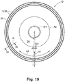
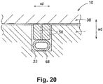
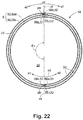
- Figs. 1 to 22 are drawings for describing one embodiment of the invention.
- Figs. 1 to 3 are for explaining the overall configuration of the scroll fluid machine.
- Figs. 4 to 22 are for describing examples of the dustproof seal structure.
- a scroll fluid machine 10 includes a case 15, a first scroll 20, a second scroll 30, and a drive mechanism 40 as its main parts.
- the first scroll is configured as a fixed scroll 20 and is secured to the case 15 via a fastener 13.
- the second scroll is configured as an orbiting scroll 30, and is arranged in a space defined by the case 15 and the fixed scroll 20.
- the invention is not limited to this example.
- the first scroll may be configured as the orbiting scroll 30 and the second scroll may be configured as the fixed scroll 20.
- the orbiting scroll 30 faces the fixed scroll 20 in an axial direction "ad" defined based on the drive mechanism 40.
- a working room 11 is formed between the fixed scroll 20 and the orbiting scroll 30.
- the orbiting scroll 30 moves relatively to the fixed scroll 20 to act on the fluid in the working room 11.
- a seal structure is provided such that a seal (seal element) S is disposed to seal between the fixed scroll 20 and the orbiting scroll 30 and to separate the working room 11 from the outside.
- contrivances are made to effectively prevent leak in the seal structure, in other words, to improve the sealability of the seal structure.
- the scroll fluid machine 10 it is possible to effectively prevent dust from flowing into the working room 11 together with fluid. Consequently it possible to effectively suppress deterioration of the inner structure of the working room 11 and to reduce the frequency of maintenance and inspection of the scroll fluid machine 10 even in use under a harsh environment such as a dusty environment. Furthermore it is possible to realize a long life of the scroll fluid machine 10. In particular, this advantageous effect is particularly useful for an oilless scroll fluid machine to which an overhaul maintenance is supposed not to carry out for a long period of time.
- seal structure provided with the seal (seal element) S described below is not limited to the scroll fluid machine, but may be applied to any other equipment that includes a first part and a second part which are movable relative to each other and opposed to each other.
- the relative movement of the first part and the second part can be various motions, for example, a turning motion, a translating motion, or a reciprocating motion.
- the seal structure having the seal S can be used not only for dustproof use but also for liquid-proof against oil, water and the like.
- the fixed scroll 20 has a base plate portion 21 having a substantially circular disk profile.
- An annular wall portion 22 is provided on the peripheral edge of the base plate portion 21.
- the annular wall portion 22 extends from the base plate portion 21 toward the orbiting scroll 30 in the axial direction "ad" of the scroll fluid machine 10.
- the annular wall portion 22 of the fixed scroll 20 is fixed to the case 15 with the fastener 13.
- a perimeter (in particular, circumferential) groove 25 is formed in the annular wall portion 22. In the groove 25, a biasing means 48 and a seal material 50 which will be described later are disposed.
- a fixed wrap 23 is provided in a region surrounded by the annular wall portion 22 of the base plate portion 21.
- the fixed wrap 23 is a standing wall provided along a spiral path when observed from the axial direction "ad" of the scroll fluid machine 10.
- the fixed wrap 23 extends from the base plate portion 21 toward the orbiting scroll 30 in the axial direction "ad" of the scroll fluid machine 10.
- a tip seal member 23a is provided at the tip of the fixed wrap 23, .
- the tip seal member 23a contacts the orbiting scroll 30.
- the tip seal member 23a hermetically seals between the fixed wrap 23 and the orbiting scroll 30.
- the base plate portion 21 has through holes.
- the through holes form an inlet 11a and an outlet 11b respectively for communicating the working room 11 with the outside.
- the inlet 11a is provided at the outer peripheral portion along the spiral path of the fixed wrap 23 and the outlet 11b is provided at the center of the spiral path of the fixed wrap 23.
- heat radiation fins 24 are provided on the base plate portion 21 on the side opposite to the fixed wrap 23.
- the orbiting scroll 30 has a base plate portion 31 arranged to face the base plate portion 21 of the fixed scroll 20.
- An orbiting wrap 33 is formed on the side of the base plate portion 31 facing the fixed scroll 20.
- the orbiting wrap 33 is a wall portion standing along a spiral path when observed from the axial direction "ad" of the scroll fluid machine 10 and has a configuration complementary to the fixed wrap 23.
- the orbiting wrap 33 extends from the base plate portion 31 toward the fixed scroll 20 in the axial direction "ad" of the scroll fluid machine 10.
- a tip seal member 33a is provided at the tip of the orbiting wrap 33.
- the tip seal member 33a contacts the fixed scroll 20.
- the tip seal member 33a hermetically seals between the orbiting wrap 33 and the fixed scroll 20.
- heat radiation fins 34 and a connecting boss 35 are provided on the base plate portion 31 on the side opposite to the orbiting wrap 33.
- the drive mechanism 40 is a mechanism for moving the orbiting scroll 30 relative to the fixed scroll 20.
- the drive mechanism 40 causes the orbiting scroll 30 to orbit relative to the fixed scroll 20 in a plane orthogonal to the axial direction "ad" of the scroll fluid machine 10.
- the orbiting scroll 30 is driven by the drive mechanism 40 to translate relative to the fixed scroll 20, in particular, translate along a circumferential path.
- the drive mechanism 40 has an electric motor 41 that supplies a rotational force and a conversion mechanism that converts the rotational motion output by the electric motor 41 into a translational motion along the circumferential orbit.
- a conversion mechanism that converts the rotational motion output by the electric motor 41 into a translational motion along the circumferential orbit.
- the conversion mechanism various known configurations may be adopted, for example, the configuration disclosed in the aforementioned patent literature ( JP7-208353A ) may be adopted.
- the conversion mechanism 42 includes a crankshaft 43 rotatally driven by the electric motor 41 and a bearing 44 fixed in the connecting boss 35 of the orbiting scroll 30.
- the crankshaft 43 includes a first shaft 43a disposed on a rotation axis "ra” of the electric motor 41 and rotationally driven by the electric motor 41, and a second shaft portion 43b defining an eccentric axis "ea” decentered from the rotation axis "ra”.
- the second shaft 43a is held by a bearing 44.
- the first shaft 43a is rotationally driven, the second shaft 43b moves in a circle about the rotation axis "ra.”
- the radius of the circle corresponds to the amount of eccentricity from the rotation axis "ra” to the eccentric axis "ea”.
- the orbiting scroll 30 is then capable of rotating about the eccentric axis "ea” with respect to the second shaft 43b via the bearing 44.
- the orbiting scroll 30 is able to orbit relative to the fixed scroll 20 through the rotation output by the electric motor 41.
- a mechanism for restricting the rotation of the orbiting scroll 30 relative to the fixed scroll 20 for example, a crankshaft or the like may be additionally provided.
- the axial direction “ad” of the scroll fluid machine 10 is defined by the rotation axis "ra” of the electric motor 41.
- the axial direction “ad” of the scroll fluid machine 10 is the direction parallel to the rotation axis "ra” of the electric motor 41. In the illustrated example, the axial direction “ad” is also parallel to the eccentric axis "ea”.
- the fixed scroll 20 opposes the orbiting scroll 30 in the axial direction "ad” of the scroll fluid machine 10.
- the case 15, the fixed scroll 20 and the orbiting scroll 30 are made of metal having high strength and excellent heat resistance.
- aluminum alloy is advantageous in that it is lightweight and excellent in heat dissipation property.
- the scroll fluid machine 10 when the orbiting scroll 30 orbits relative to the fixed scroll 20 as driven by the drive mechanism 40, the fixed wrap 23 and the orbiting wrap 33 repeatedly approach and separate to/from each other in regions along the spiral path of the fixed wrap 23. Thereby fluid as an internal medium is compressed or expanded along the spiral path of the fixed wrap 23 in the working room 11.
- the air is compressed from the outer peripheral region along the spiral path of the fixed wrap 23 toward the center region.
- the air with increased pressure is obtained and supplied to the outside through the outlet 11b.
- the air is sucked from the inlet 11a located at the outer peripheral portion along the spiral path of the fixed wrap 23.
- the scroll fluid machine 10 functions as a compressor.
- the heat radiation fins 24 and 34 are provided on the fixed scroll 20 and the orbiting scroll 30 respectively.
- a cooling medium is supplied to the radiation fins 24, 34 by a cooling device (not shown), and performs heat exchange with the heat radiation fins 24, 34.
- the cooling device may be a blower that blows air onto the heat radiation fins 24, 34.
- Scroll fluid machines serving as compressors are used in various fields including vehicles such as train cars and automobiles.
- a conventional scroll fluid machine is used under severe environments such as dusty environment, a trouble could occur such that the life of the tip seal provided at the tip of the wrap becomes extremely short.
- the scroll fluid machines may be configured as oilless, which has been regarded as a major advantage that it is not necessary to perform maintenance over a certain period of time.
- deterioration of the tip seal member occurred when the machine is used under severe environments is a significant disadvantage for the scroll fluid machine, which can be a reason for limiting the fields where the scroll fluid machines are used.
- the scroll fluid machine 10 in the embodiment has a dustproof seal structure using the seal (seal element) S described below.
- the seal material 50 forming the seal S exhibits a dustproof property as a dustproof seal member when applied to the scroll fluid machine 10.
- the seal S used in the first embodiment includes one or more annular seal members 50 disposed between and in contact with a first component 20 and a second component 30 that are movable relative to each other and face each other.
- the dustproof seal member 50 has a cut CU defined by two portions 51, 52 that overlap each other in a width direction of the dustproof seal member 50.
- the dustproof seal member 50 may be configured as an elongated strip member extending in the longitudinal direction.
- the width direction of the seal S or the seal member 50 is a direction orthogonal to both the axial direction "ad” and the longitudinal direction of the dustproof seal member 50 and coincides with the radial direction "rd” described later in the example below. Therefore, in the following description, the same reference sign "rd" as the radial direction is used for the width direction.
- the cut CU of the dustproof seal member 50 is not limited to a portion formed by cutting a continuous member.
- the cut CU encompasses a discontinuous site located between the two separate portions 51 and 52 without limited by the way the site is formed.
- the two portions 51, 52 defining the cut CU, or the two portion 51, 52 defining the cutting part CU, or the two portions 51, 52 located on either sides of the cut CU respectively are movable relative to each other while overlapping in the width direction. Therefore, as will be described later, when the total length of the dustproof seal member 50 is increased due to thermal expansion, the two portions 51 and 52 are able to move in the longitudinal direction thereof. At this point, by maintaining the state in which the two portions 51 and 52 overlap in the width direction, it is possible to maintain the sealing in the region of the cut CU and to effectively prevent leak around the cut CU. This effectively prevents dust from flowing into the working room 11 and thereby it is possible to effectively prevent unexpected and early deterioration of the tip seal members 23a, 33a of the fixed wrap 23 and the orbiting wrap 33 respectively.
- the two portions 51, 52 defining the cut CU be movable relative to each other within a range where their overlapping state in the width direction "rd" is maintained. That is, it is preferable that the two portions 51, 52 defining the cut CU are maintained in the state where they overlap each other in the width direction "rd” irrespective of their relative movement. In this configuration, it is possible to effectively and stably prevent leak at the cut CU.
- the length of the seal member 50 may be adjusted such that the two portions 51, 52 defining the cut CU overlap with each other in the width direction "rd" even when the temperature of the seal member 50 has not risen yet, for example, when the equipment or device having the seal member 50 such as the scroll fluid machine 10 is not operated.
- the two portions 51, 52 defining the cut CU are designed structurally movable relative to each other within a range where the overlapping in the width direction "rd" is maintained.
- the width of the seal member 50 at the cut CU is equal to or smaller than the width at the other portions of the dustproof seal member 50. That is, in the region where the cut CU is provided, the two portions 51, 52 of the dustproof seal member 50 overlap in the width direction "rd" but the width thereof is not increased compared to the other portions thereof. Therefore, installation of the seal member 50, for example, installation of the seal member 50 in the groove 25 as described later can be performed easily and accurately. Further, the width of the circumferential groove 25 can be made constant. As a result, it is possible to further improve the seal performance of the seal S.
- the seal S includes a single seal member 50, but as in the tenth example to be described later, the seal S may include a plurality of the seal members 50.
- the seal S may include a plurality of the seal members 50.
- a fitting portion 55 is formed in the end portions 51, 52 of the strip-shaped dustproof seal member 50.
- the cut CU is formed in the fitting portion 55. That is, in the following example, the portions defining the cut CU is the end portion 51 and the end portion 52 of the dustproof seal member 50.
- the configurations described below are merely examples, and various modifications are possible.
- the groove 25 is formed in the fixed scroll 20 (see Fig. 2 ).
- the groove 25 is formed so as to surround the working room 11.
- the groove 25 is provided in a region that always faces the peripheral edge of the orbiting scroll 30 regardless of the relative position of the orbiting scroll 30 to the fixed scroll 20.
- the groove 25 may be provided in the orbiting scroll 30, without being limited to the above example.
- the groove 25 has a constant width in the radial direction.
- the invention is not limited to this example, and the width of the groove 25 may be varied.
- groove 25 having the constant width, it is possible to facilitate the formation of the groove. In addition, as will be described later, it is possible to easily place the seal member 50 having the cut CU in the groove 25.
- the direction along the locus of the circumference surrounding the working room 11 is referred to as the circumferential direction "cd”.
- a direction orthogonal to both the axial direction “ad” and the circumferential direction “cd” is referred to as the radial direction "rd”.
- the longitudinal direction of the dustproof seal member 50 provided in the scroll fluid machine 10 coincides with the circumferential direction "cd”
- the width direction of the dustproof seal member 50 coincides with the radial direction "rd”.
- the “inner” side in the width direction “rd” or the radial direction “rd” is on the inner side of the circumference defined by the circumferential direction “cd” and the side closer to the rotation axis "ra” of the scroll fluid machine 10.
- the “outer” side in the width direction “rd” or the radial direction “rd” is on the outer side of the circumference defined by the circumferential direction “cd” and the side further from the rotation axis "ra” of the scroll fluid machine 10.
- the biasing means 48 and the dustproof seal member 50 are provided in the groove 25.
- the biasing means 48 biases the dustproof seal member 50 in the axial direction "ad” and presses the dustproof seal member 50 so as to contact the orbiting scroll 30 from the fixed scroll 20.
- the biasing means 48 may be formed of an elastic member.
- the biasing means 48 is formed of an annular lubber. Without limited to this example, the biasing means 48 may be arranged dispersedly in the circumferential direction "cd”. As shown in Fig. 3 , the fixed scroll 20 and the orbiting scroll 30 are tightly sealed in the axial direction "ad” by the basing means 48 and the dustproof seal member 50.
- the dustproof seal member 50 is a member that abuts against the orbiting scroll 30 and fills a gap between the fixed scroll 20 and the orbiting scroll 30. Therefore, a material having friction resistance and sealing properties, for example, rubber or resin may be selected as the material for the dustproof seal member 50.
- the sealing performance of the dustproof seal structure is improved by the geometry of the dustproof seal member 50.
- the dustproof seal member 50 is initially configured as a linear strip-shaped member.
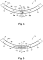
- the dustproof seal member 50 is then disposed such that the end portions 51, 52 overlap in the radial direction "rd" (the width direction of the dustproof seal member 50) that is orthogonal to the circumferential direction "cd" (the longitudinal direction of the dustproof seal member 50), and subsequently the cut CU is formed between the end portions 51, 52 as shown in Fig. 4 .
- the end portions 51, 52 overlap with each other in the width direction "rd” and thereby the fitting portion 55 is formed.
- the dustproof seal member 50 surrounds the working room 11 from the entire circumference thereof.
- the dustproof seal member 50 surrounds the working room 11 and seals between the fixed scroll 20 and the orbiting scroll 30. Note that illustration of the working room 11, the fixed wrap 23 and the like is omitted in Fig. 4 and Figs. 5 to 22 which will be referred later.
- the strip-shaped dustproof seal member 50 has an inner end portion (inner portion) 51 situated on the relatively inner side in the width direction "rd," and an outer end portion (outer portion) 52 situated on the relatively outer side in the width direction "rd” as the end portions forming the fitting portion 55. That is, the outer end portion 52 is located outside the inner end portion 51 in the radial direction "rd".
- the dustproof seal member 50 further has an intermediate portion 53 situated between the inner end portion 51 and the outer end portion 52. In the illustrated example, the intermediate portion 53 has a constant width. Whereas the inner end portion 51 and the outer end portion 52 are tapered.
- the width of the portion of the dustproof seal member 50 where the end portions 51 and 52 overlap in the width direction "rd" is equal to or smaller than the width of the other portions of the dustproof seal member in the width direction rd. In the illustrated example, these widths are the same. Therefore the dustproof seal member 50 can be accommodated in the circumferential groove 25 having the constant width while forming the fitting portion 55. Attachment of the seal S formed by the dustproof seal member 50 can be easily performed, in particular, the seal S can be easily placed in the groove 25.
- the inner end portion (inner portion) 51 is formed such that an outer side surface 51b facing outward in the radial direction "rd" is inclined with respect to an outer side surface 53b of the portion 53 adjacent to the inner end portion 51 of the dustproof seal member 50.
- An inner side surface 51a of the inner end portion 51 facing inward in the radial direction "rd” is arranged on the line continuously extending from an inner side surface 53a of the portion 53 adjacent to the inner end portion 51 of the dustproof seal member 50.
- An inner side surface 52a of the outer end portion (outer portion) 52 facing inward in the radial direction "rd” is inclined with respect to the inner side surface 53a of the portion 53 adjacent to the outer end portion 52 of the dustproof seal member 50.
- An outer side surface 52b of the outer end portion 52 facing outward in the radial direction "rd” is arranged on the line continuously extending from the outer side surface 53b of the portion 53 adjacent to the end portion 52 of the dustproof seal member 50.
- the dustproof seal member 50 described above When the dustproof seal member 50 described above is used, it is possible to effectively prevent dust from flowing into the working room 11 through the dustproof seal structure together with the leaked outside air.
- the inventors conducted intensive studies and found that one of the main reasons for causing early deterioration of the tip seal members 23a, 33a is that a part of a cooling wind directed to the heat radiation fins 24, 34 flows into the working room 11 where becomes a negative pressure during operation of the scroll fluid machine 10.
- the dustproof seal member 50 shown in Fig. 4 is able to effectively prevent leak at the fitting portion 55 (the cut CU) during the operation of the scroll fluid machine 10 which is required to have airtightness of the dustproof seal structure.
- the dustproof seal member 50 contacting the fixed scroll 20 and the orbiting scroll 30 is heated and expanded with the air compression in the working room 11 between the fixed scroll 20 and the orbiting scroll 30.
- the material of the dustproof seal member 50 which is required to have airtightness and friction resistance properties, usually has a higher linear expansion coefficient than the material used for the scrolls 20, 30.
- the dustproof seal member 50 has the elongated shape so that it is easily expanded in the longitudinal direction in terms of shape. Therefore, during the operation of the scroll fluid machine 10, the dustproof seal member 50 expands. Consequently, the outer side surface 51b of the inner end portion 51 and the inner side surface 52a of the outer end portion 52 are pressed against each other as indicated by the arrows in Fig.
- the dustproof seal member 50 hermetically seals between the fixed scroll 20 and the orbiting scroll 30 at the fitting portion 55 (the cut CU), and thereby it is possible to effectively prevent the fluid (the outside air) from flowing between the end portions 51.
- the width of the dustproof seal member 50 at the cut CU is equal to or smaller than the width at the other portion of the dustproof seal member 50. Therefore, it is unnecessary to change the width of the groove 25 formed in the fixed scroll 20 to accommodate the dustproof seal member 50. In this way, it is possible to stabilize the position of the dustproof seal member 50 in the groove 25, and to maintain the state where the outer side surface 51b of the inner end portion 51 contacts the inner side surface 52a of the outer end portion 52. In this light, leak at the fitting portion 55 can be more effectively prevented.
- the dustproof seal member 50 is the strip-shaped member that is held by one of the fixed scroll 20 and the orbiting scroll 30 and abuts against the other of the fixed scroll 20 and the orbiting scroll 30.
- the dustproof seal member 50 forms the fitting portion 55 such that the end portions 51, 52 overlap in the radial direction "rd" orthogonal to the circumferential direction "cd", and surrounds the working room 11.
- the inner end portion 51 is tapered such that its outer side surface 51b is inclined with respect to the outer side surface 53b of the portion 53 adjacent to the inner end portion of the dustproof seal member 50.
- the outer end portion 52 is tapered such that its inner side surface 52a is inclined with respect to the inner side surface 53a of the portion 53 adjacent to the outer end portion 52 of the dustproof seal member 50. Further, the outer side surface 51b of the inner end portion 51 and the inner side surface 52a of the outer end portion 52 abut each other. According to the first example described above, leak at the fitting portion 55 can be effectively prevented. Consequently it is possible to effectively prevent dust from flowing into the working room 11 and thereby it is possible to effectively prevent unexpected and early deterioration of the tip seal members 23a, 33a of the fixed wrap 23 and the orbiting wrap 33 respectively.
- the portions 51, 52 defining the cut CU (the end portions of the dustproof seal member 50) have the geometry that can prevent leak at the cut CU (the fitting portion 55) in the same manner as the first example. Also in the example shown in Fig. 5 , the end portions 51, 52 of the dustproof seal member 50 defining the cut CU overlap with each other in the width direction (radial direction) "rd" to form the fitting portion 55. In this way, the dustproof seal member 50 circumferentially surrounds the working room 11.
- the dustproof seal member 50 has the end portions 51, 52 and the intermediate portion 53 situated between the end portions 51, 52.
- the intermediate portion 53 may have a constant width.
- One end portion (one portion defining the cut CU) of the dustproof seal member 50 has a recessed portion 51c recessed in its end surface in the circumferential direction "cd".
- the other end portion (the other portion defining the cut CU) of the dustproof seal member 50 has a convex portion 52c that protrudes from its end surface in the circumferential direction "cd" and is inserted into the concave portion 51c.
- the fluid (gas) flowing between the end portions 51, 52 that form the cut CU and leaking from the fitting portion 55 (the cut CU) needs to advance by the twice of the depth which the convex portion 52c penetrates into the concave portion 51c.
- the fluid leaking from the fitting portion 55 needs to turn back in the travel direction along the circumferential direction "cd" in the recess 51c. In this way, sealing between the fixed scroll 20 and the orbiting scroll 30 is effectively provided and thereby leak at the fitting portion 55 can be effectively prevented. Consequently, it is possible to prevent dust from flowing into the working room 11 and thereby unexpected and early deterioration of the tip seal members 23a, 33a of the fixed wrap 23 and the orbiting wrap 33 respectively can be effectively prevented.
- the portions 51, 52 defining the cut CU are movable relative to each other in the circumferential direction "cd" within a range where their overlapping state in the width direction "rd” is maintained. That is, the dustproof seal member 50 is thermally expandable and contractable in the groove 25 while maintaining the constant width. Therefore, it is unnecessary to change the width of the groove 25 formed in the fixed scroll 20. Consequently it possible to stabilize the placement of the dustproof seal member 50 in the groove 25 and to maintain the state in which the convex portion 52c of the other end portion 52 has entered the recess 51c of the one end portion 51. In this light, the leak at the fitting portion 55 (the cut CU) can be more effectively prevented.
- the concave portion 51c shown in Fig. 5 may be formed in one of the outer side surface 51b of the inner end portion (inner portion) 51 and the inner side surface 52a of the outer end portion (outer portion) 52, and the convex portion 52c shown in Fig. 5 may be formed in the other of the outer side surface 51b of the inner end portion (inner portion) 51 and the inner side surface 52a of the outer end portion (outer portion) 52.
- the portions 51, 52 defining the cut CU have the geometry that can prevent leak at the fitting portion in the same manner as the first and second examples.
- the end portions 51, 52 of the dustproof seal member 50 overlap with each other in the width direction "rd" to form the fitting portion 55. In this way, the dustproof seal member 50 circumferentially surrounds the working room 11.
- the strip-shaped dustproof seal member 50 has the inner end portion (inner portion) 51 situated on the relatively inner side in the radial direction "rd," and the outer end portion (outer portion) 52 situated on the relatively outer side in the radial direction "rd” as the end portions forming the fitting portion 55. That is, the outer end portion 52 is located outside the inner end portion 51 in the width direction "rd".
- the dustproof seal member 50 further has an intermediate portion 53 situated between the inner end portion 51 and the outer end portion 52.
- the intermediate portion 53 may have a constant width.
- the inner end portion (inner portion) 51 has a base portion 51d that has a width smaller than a width "wm" of the portion 53 adjacent to the inner end portion 51 of the dustproof seal member 50, and a wide portion 51e that is situated closer to the tip of the dustproof seal member 50 along the longitudinal direction (direction coinciding with the circumferential direction "cd") compared to the base portion 51d and that has a width larger than the base portion 51d.
- the outer end portion (outer portion) 52 has a base portion 52d that has a width smaller than the width "wm" of the portion 53 adjacent to the outer end portion 52 of the dustproof seal member 50, and a wide portion 52e that is situated closer to the tip of the dustproof seal member 50 along the longitudinal direction compared to the base portion 52d and that has a width larger than the base portion 52d.
- the wide portion 51e of the inner end portion 51 faces the base portion 52d of the outer end portion 52 in the width direction "rd," and the wide portion 52e of the outer end portion 52 faces the base portion 51d of the inner end portion 51 in the width direction "rd.”
- the fluid (gas) flowing between the end portions 51, 52 that form the cut CU and leaking from the fitting portion 55 (the cut CU) needs to go through a gap between the wide portion 51e of the inner end portion 51 and a gap between the wide portion 52e of the outer end portion 52 and the base portion 51d of the inner end portion 51. Furthermore, it is possible to secure a relatively long length in which the end portions 51, 52 are arranged in parallel in the circumferential direction "cd". In this light, leak at the fitting portion 55 can be effectively prevented. Consequently, it is possible to prevent dust from flowing into the working room 11 and thereby unexpected and early deterioration of the tip seal members 23a, 33a of the fixed wrap 23 and the orbiting wrap 33 respectively can be effectively prevented.
- the portions 51, 52 defining the cut CU are movable relative to each other in the circumferential direction "cd" within a range where their overlapping state in the width direction "rd” is maintained. That is, the dustproof seal member 50 is thermally expandable and contractable in the groove 25 while maintaining the constant width. Therefore, it is unnecessary to change the width of the groove 25 formed in the fixed scroll 20. Consequently it possible to stabilize the placement of the dustproof seal member 50 in the groove 25 and to maintain the state in which the convex portion 52c of the other end portion 52 has entered the recess 51c of the one end portion 51. In this light, the leak at the fitting portion 55 (the cut CU) can be more effectively prevented.
- the sum of a width "w1e" of the wide portion 51e of the inner end portion (inner portion) 51 and a width "w2d” of the base portion 52d of the outer end portion (outer portion) 52 may be same as or larger than the width "wm” of the intermediate portion 53 adjacent to the outer end portion 52 of the dustproof seal member 50.
- the sum of a width "w2e" of the wide portion 52e of the outer end portion (outer portion) 52 and a width "w1d” of the base portion 51d of the inner end portion (inner portion) 51 may be same as or larger than the width "wm” of the intermediate portion 53 adjacent to the inner end portion 51 of the dustproof seal member 50.
- the scroll fluid machine 10 of the fourth example further includes a pressing means 60 for pressing the one portion defining the cut CU toward the other portion.
- the scroll fluid machine 10 further has the pressing means 60 for pressing one end portion 51 forming the fitting portion 55 of the dustproof seal member 50 toward the other end portion 52.
- the pressing means 60 may be configured to press one portion 51 defining the cut CU in the width direction (radial direction) "rd” toward the other portion 52 defining the cut CU, and press the other portion 52 toward the one portion 51 in the width direction (radial direction) "rd”.
- the pressing means 60 may be configured to press the one portion 51 inwardly or outwardly in the width direction (radial direction) "rd” toward the other portion 52 supported by the wall defining the groove 25, and the portions 51 and 52 defining the cut CU may be brought into contact with each other by being pressed by the wall of the groove 25 and the pressing means 60.
- the scroll fluid machine 10 has a first pressing means 61 and a second pressing means 62.
- the first pressing means 61 urges the inner end portion (inner portion) 51 toward the outer side in the radial direction "rd” and biases the inner end portion 51 such that the inner end portion 51 contacts the outer end portion (outer portion) 52.
- the second pressing means 62 urges the outer end portion (outer portion) 52 toward the inner side in the radial direction "rd” and biases the outer end portion 52 such that the outer end portion 52 contacts the inner end portion (inner portion) 51.
- an accommodation space 26 for accommodating the first pressing means 61 is formed at a position on the inner side of the groove 25 in the radial direction "rd"
- an accommodation space 26 for accommodating the second pressing means 62 is formed at a position on the outer side of the groove 25 in the radial direction "rd.”
- the pressing means 61, 62 each have plate members 61a, 62a and elastic members 61b, 62b respectively stored in the accommodation spaces 26.
- the plate members 61a, 62a are fixed to the fixed scroll 20 at one end thereof. The other ends of the plate members 61a, 62a are pressed against the elastic members 61b, 62b respectively.
- the elastic members 61b, 62b press the corresponding plate members 61a, 62a toward the fitting portion 55 of the dustproof seal member 50 accommodated in the groove 25.
- the pressing means 61, 62 shown are configured to press one end toward the other end along the radial direction "rd".
- the elastic members 61b, 62b are formed of compression springs, but the invention is not limited to this.
- the elastic members 61b, 62b may be formed of a rubber tube or the like, for example.
- first pressing means 61 or the second pressing means 62 may be omitted in the examples shown in Figs. 7 and 8 .
- the dustproof seal member 50 has the configuration similar to the dustproof seal member of the first example as the end portions 51 and 52 forming the fitting portion 55 (the cut CU).
- the invention is not limited to this.
- the pressing means 60 can be applied to any form of the dustproof seal member 50 such as ones described in the second example or the third example.
- the specific configuration of the pressing means 60 is not limited to the examples shown in Figs. 7 and 8 , and various configurations can be adopted.
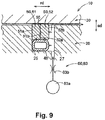
- the pressing means 60 includes a fluid jetting mechanism 63 in the example shown in Fig. 9 .
- the fluid ejection mechanism 63 is a mechanism capable of ejecting fluid such as a gas and a liquid, and includes a fluid source 63a and an orifice 63b through which a fluid supplied from the fluid source 63a passes.
- an ejection port 27 is formed on the bottom of the groove 25. The fluid that has passed through the orifice 63b is ejected into the groove 25 through the ejection port 27.
- the ejection port 27 is offset from the center of the bottom surface of the groove 25 in the radial direction "rd.” Therefore, the pressure in the groove 25 becomes higher on one side in the radial direction "rd” and becomes lower on the other side in the radial direction "rd”. As a result, one end situated on the one side in the radial direction "rd” is pressed toward the other end situated on the other side in the radial direction "rd”.
- the dustproof seal member 50 is the strip-shaped dustproof member that is held by one of the fixed scroll 20 and the orbiting scroll 30 and abuts against the other of the fixed scroll 20 and the orbiting scroll 30.
- the dustproof seal member 50 forms the fitting portion 55 such that the two portions (the end portions) 51, 52 defining the cut CU overlap in the width direction (radial direction) "rd" orthogonal to the circumferential direction "cd", and surrounds the working room 11.
- the scroll fluid machine 10 further has the pressing means 60 for pressing one end portion of the dustproof seal member 50 toward the other end portion.
- the pressing means presses one portion (the end portion) defining the cut CU toward the other portion (the end portion) defining the cut CU along the width direction (radial direction) "rd.” According to this pressing means, it is possible to retain the one portion (end portion) to be stably in contact with the other portion (end portion), whereby leak at the fitting portion 55 can be more effectively prevented.
- the pressing means may include elastic members 61b, 62b.
- Such a pressing means has a simple structure and can be manufactured at a low cost while it can stably supply the pressing force.
- the pressing means 60 includes a fluid ejection mechanism 63 in the example shown in Fig. 9 .
- a fluid ejection mechanism 63 By using the fluid ejected from the fluid ejection mechanism 63, one portion (end portion) defining the cut CU is pressed toward the other portion (end portion) defining the cut CU in the radial direction "rd", and the one portion (end portion) can be maintained to be stably contacted with the other portion (the end portion), whereby leak at the fitting portion 55 can be more effectively prevented.
- the biasing means 48 is also pressed in the width direction (radial direction) "rd".
- the annular biasing means 48 having the hollow circular cross section receives a pressing force in the radial direction "rd” by the fluid from the fluid ejection mechanism 63 and deforms so as to expand in the axial direction "ad".
- the dustproof seal member 50 and the orbiting scroll 30, the dustproof seal member 50 and the biasing means 48, and the biasing means 48 and the groove 25 are respectively brought into close contact with each other, and thereby the fixed scroll 20 and the orbiting scroll 30 can be more stably sealed.
- the biasing means 48 and the dustproof seal member 50 are pressed inward in the radial direction "rd”. That is, the biasing means 48 and the dustproof seal member 50 are pressed toward the side wall located on the inner side of the groove 25 in the axial direction "ad”.
- the fluid ejected from the fluid ejecting mechanism 63 flows outward in the radial direction "rd” from the gap between the fixed scroll 20 and the orbiting scroll 30, and is eventually discharged to the outside. In this way, entry of dust from the outside through the gap can be more effectively prevented.
- the circumferential groove 25 surrounding the working room 11 is formed in the fixed scroll 20 or the orbiting scroll 30, and the dustproof seal member 50 is arranged in the groove 25.
- the fluid ejection mechanism 63 ejects fluid into the groove 25.
- the fluid ejection mechanism 63 can be applied to the existing scroll fluid machine 10 without restricting the configuration of the scroll type fluid machine 10.
- the circumferential groove 25 surrounding the working room 11 is formed in the fixed scroll 20 or the orbiting scroll 30, and the dustproof seal member 50 is arranged in the groove 25.
- the two portions (the end portions of the dustproof seal member 50) 51, 52 defining the cut CU overlap with each other in the width direction (radial direction) "rd" to form the fitting portion 55. In this way, the dustproof seal member 50 circumferentially surrounds the working room 11.
- the dustproof seal member 50 has the inner end portion (inner portion) 51 and the outer end portion (outer portion) 52 located on the outer side of the inner end portion 51 in the width direction (radial direction) "rd" as the two portions defining the cut CU (the end portions forming the fitting portion 55).
- an inner protrusion (inner lip) 51f that protrudes inward in the radial direction "rd” from the inner side surface 51a of the inner end portion 51 facing inward in the radial direction "rd”, and/or an outer protrusion (outer lip) 52f that protrudes outward in the radial direction "rd” from the outer side surface 52b of the outer end portion 52 facing outward in the radial direction "rd” is/are provided.
- the inner end portion 51 is provided with the inner protrusion 51f and the outer end portion 52 is provided with the outer protrusion 52f.
- the inner protrusion 51f abuts against the wall surface of the groove 25 situated on the inner side in the radial direction "rd” and pushes the inner end portion 51 toward the outer end portion 52 in the radial direction "rd”.
- the outer protrusion 52f abuts against the wall surface of the groove 25 situated on the outer side in the radial direction "rd” and pushes the outer end portion 52 toward the inner end portion 51 in the radial direction "rd”.
- the two portions 51, 52 (the end portions of the dustproof seal member 50) defining the cut CU are maintained in a state of being in contact with each other in the width direction (radial direction) "rd.” Therefore, it is possible to effectively prevent leak at the fitting portion 55.
- the pressing means 60 in the fourth example it is also possible to omit the inner protrusion 51f or the outer protrusion 52f.
- the inner protrusion 51f and the outer protrusion 52f be elastically deformable. Further, to prevent leak at the fitting portion 55 effectively, it is preferable that the sum of the maximum width in the radial direction "rd" of the inner end portion 51 including the inner protrusion 51f and the maximum width in the radial direction "rd" of the outer end portion 52 including the outer protrusion 52f is larger than the sum of the maximum width of the groove 25 in the radial direction "rd”.
- the inner protrusion 51f tapers toward the inner side in the radial direction "rd"
- the outer protrusion 52f tapers toward the outer side in the radial direction "rd”.
- the inner protrusion 51f includes a tip-end side surface 51fa and a base-end side surface 51fb opposed in the longitudinal direction (direction corresponding to the circumferential direction "cd") of the dustproof seal member 50.
- the tip-end side surface 51fa is the surface situated closer to the tip end of the inner end portion 51 in the longitudinal direction of the dustproof seal member 50
- the base-end side surface 51fb is the surface situated closer to the intermediate portion 53 in the longitudinal direction of the dustproof seal member 50.
- the angle " ⁇ 1a” (strictly speaking, the smaller one of the complementary angles) of the tip-end side surface 51fa with the longitudinal direction of the dustproof seal member 50 is smaller than the angle " ⁇ 1b" (strictly speaking, the smaller one of the complementary angles) of the base-end side surface 51fb with the longitudinal direction of the dustproof seal member 50.
- the inner protrusion 51f is configured as described above, the inner protrusions 51f will move smoothly in the groove 25 during the dustproof seal member 50 is thermally expanded. Consequently it is possible to prevent the dustproof seal member 50 from being meandering, twisting, or deflected in the groove 25, and stabilize the placement of the dustproof seal member 50 in the groove 25.
- the outer protrusion 52f is also configured similarly to the inner protrusion 51f. That is, the outer protrusion 52f includes a tip-end side surface 52fa and a base-end side surface 52fb that face in the longitudinal direction of the dustproof seal member 50.
- the tip-end side surface 52fa is the surface situated closer to the tip end of the outer end portion 52 in the longitudinal direction of the dustproof seal member 50
- the base-end side surface 52fb is the surface situated closer to the intermediate portion 53 in the longitudinal direction of the dustproof seal member 50.
- the angle " ⁇ 2a" of the tip-end side surface 52fa with the longitudinal direction of the dustproof seal member 50 is smaller than the angle " ⁇ 2b" of the base-end side surface 51fb with the longitudinal direction of the dustproof seal member 50.
- leak at the cut CU the fitting portion 55
- the configuration of the outer protrusion 52f can be more stably prevented also with the configuration of the outer protrusion 52f.
- the circumferential groove 25 surrounding the working room 11 is formed in the fixed scroll 20 or the orbiting scroll 30, and the dustproof seal member 50 is arranged in the groove 25.
- the two portions (the end portions of the dustproof seal member 50) 51, 52 defining the cut CU overlap with each other in the width direction (radial direction) "rd" to form the fitting portion 55. In this way, the dustproof seal member 50 circumferentially surrounds the working room 11.
- the pasty material 28 is filled in at least a region around the cut CU (the fitting portion 55) in the groove 25.
- the pasty material 28 includes a semisolid material or a highly viscous material.
- grease can be used as the pasty material 28.
- grease is used as a lubricant in mechanical devices and the like.
- the pasty material 28 captures dust and the like, in addition to preventing the leak at the cut CU (the fitting portion 55).
- the pasty material 28 captures dust and the like, the pasty material gradually loses its fluidity and is eventually hardened. Normally, the cured pasty material 28 cannot achieve its original purpose (for example, the grease used for lubrication).
- this function of the pasty material 28 is suitable for, in particular, an oilless scroll fluid machine 10 having low maintenance frequency.
- the two portions 51 and 52 defining the cut CU are shown, however the illustrated configuration is merely an example.
- the pasty material 28 also effectively functions at the joint portion of the biasing means.
- the pasty material 28 can also function effectively for the cut CU (the fitting portion 55) shown in Figs. 10 and 11 and the other cut portion (a fitting portion).
- the pasty material 28 is provided on the outer side surface 51b of the inner end portion (inner portion) 51.
- the pasty material 28 may be provided on the inner side surface 52a of the outer end portion (outer portion) 52, or provided on both the outer side surface 51b of the inner end portion (inner portion) 51 and the inner side surface 52a of the outer end portion (the outer portion) 52.
- the pasty material 28 is filled between the two end portions 51 and 52 defining the cut CU in the groove 25, preferably in the area around the fitting portion 55.
- the pasty material 28 seals between the two portions (both end portions 51, 52 at the fitting portion 55) defining the cut CU, the pasty material 28 is capable of preventing leak at the cut CU and collecting dust. Further, the fluidity of the pasty material 28 is lowered by capturing dust. The pasty material 28 with the reduced fluidity is able to stay at the cut CU (the fitting portion 55) to continue to exhibit the leak preventing function and the dust capturing function, and therefore is particularly effective for the scroll fluid machine 10 of the oil-free type.
- the seal S used in the second embodiment is endless-annular metal first seal portion Sa disposed on one of the first component 20 and the second component 30 movable relative to each other, and a endless-annular second seal portion Sb that is made of resin or rubber and disposed on the first seal portion Sa to contact the other of the first component 20 and the second component 30.
- the aspect of the second embodiment it is possible to improve the airtightness by not providing the fitting portion. Further, with the first seal portion Sa made of metal which is hardly thermally deformed as compared with resins and rubber widely used, it is possible to enhance the rigidity and durability of the seal S and to effectively suppress the thermal expansion and contraction. This makes it possible to effectively prevent meandering or twisting of the dustproof seal member 50. Furthermore, since the seal also includes the second seal portion Sb made of resin or rubber, it is possible to ensure tight sealability with the first component or the second component. Therefore, according to the second aspect, it is possible to tightly seal between the first component 20 and the second component.
- the second aspect with the combination of the first seal portion Sa that is hardly deformed by heat and the second seal portion Sb that has an excellent sealing property, it is possible to stably seal between the first component 20 and the second component 30.
- the scroll fluid machine 10 it is possible to prevent dust from flowing into the working room 11 and thereby unexpected and early deterioration of the tip seal members 23a, 33a of the fixed wrap 23 and the orbiting wrap 33 respectively can be effectively prevented.
- the thickness of the second seal portion Sb (the dimension of the second seal portion Sb along the axial direction "ad") be smaller than the thickness of the first seal portion Sa (the dimension of the seal portion Sa along the axial direction "ad").
- the aspect ratio (the ratio of the height to the width) of the second seal portion Sb is smaller than the aspect ratio (the ratio of the height to the width) of the first seal portion Sa.
- first seal portion Sa and the second seal portion Sb may be integrally formed to form a single dustproof seal member 50. Such an example is shown in a seventh example to be described later. In addition, the first seal portion Sa and the second seal portion Sb may form a separate dustproof seal member 50 respectively. Such an example is shown in an eighth example to be described later.
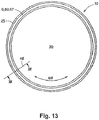
- the seventh example of the dustproof seal structure will be described with mainly reference to Figs. 13 and 14 .
- the dustproof seal member is not provided with the fitting portion, thereby improving the airtightness using the dustproof seal member 50.
- the dustproof seal member 50 formed as a single body is provided between the fixed scroll 20 and the orbiting scroll 30 as the seal (seal element) S.
- the dustproof seal member 50 includes the first seal portion Sa has an endless annular shape and is of metal, and the second seal portion Sb that has an endless annular shape and is made of resin or rubber.
- the dustproof seal member 50 illustrated in Figs. 13 and 14 is held by one of the fixed scroll 20 and the orbiting scroll 30 and abuts against the other of the fixed scroll 20 and the orbiting scroll 30.
- the dustproof seal member 50 surrounds the working room 11 and seals between the fixed scroll 20 and the orbiting scroll 30.
- the dustproof seal member 50 has an endless annular main body portion 56 made of metal.
- the fitting portion 55 is provided to allow the dustproof seal member 50 to thermally expand and contract in the groove 25 formed in one of the scrolls 20, 30.
- the temperature of the scrolls 20, 30 rise mainly due to air compression in the working room 11.
- the temperature of the dustproof seal member 50 also changes.
- the dustproof seal member 50 thermally deforms due to the temperature change of the dustproof seal member 50.
- the dustproof seal member 50 is formed using resin or rubber which is easily thermally deformed.
- the dustproof seal member 50 has the endless annular main body portion 56 made of metal.
- the annular main body portion 56 forms the first seal portion Sa of the seal (seal element) S.
- the annular main body portion 56 is formed of metal which is hardly deformed by heat as compared with the resin and the rubber which have been widely used heretofore.
- the material used for the scrolls 20, 30 is generally metal having high rigidity and abrasion resistance similarly to the annular main body portion 56. Therefore, the annular main body portion 56 made of metal can effectively suppress the thermal expansion and the thermal shrinkage, and further exhibits a deformation behavior similar to the groove 25 that holds the annular main body portion 56.
- the metal annular main body portion 56 itself has high rigidity so that it is hardly deformed or twisted. Consequently, the endless annular main body portion 56 made of metal effectively prevents meandering or twisting in the groove 25 during the operation of the scroll fluid machine 10 even without the fitting portion 55. And it is possible to stably seal between the fixed scroll 20 and the orbiting scroll 30. Moreover, leak from the gap between the end portions at the fitting portion 55 can be prevented, so that entry of dust into the working room 11 can be effectively prevented.
- the material of the fixed scroll 20 and the orbiting scroll 30 an aluminum alloy is widely used because of its an appropriate rigidity, an excellent heat radiation property, and its light weight. It is preferable that the annular main body portion 56 is made of aluminum or an aluminum alloy.
- the linear expansion coefficients of the annular main body portion 56 and the scrolls 20, 30 in which the groove 25 is formed are about the same, so that it is possible to effectively prevent the dustproof seal member 50 from being meandered, deflected or twisted in the groove 25 due to the difference in the expansion rate and contraction rate. Therefore it is possible to more stably seal between the fixed scroll 20 and the orbiting scroll 30.
- the dustproof seal member 50 further includes a fluorine-based resin layer 57 laminated on the annular main body portion 56 in the illustrated example.
- the fluorine-based resin layer 57 forms the second seal portion Sb of the seal (seal component) S.
- This fluorine-based resin layer 57 contacts the scroll (the orbiting scroll 30 in the illustrated example) disposed opposite to the scroll holding the dustproof seal member 50.
- the fluorine-based resin layer 57 has excellent friction resistance as typified by polytetrafluoroethylene (PTFE), for example. Therefore, by providing the fluorine-based resin layer 57, it is possible to effectively prevent wear of the dustproof seal member 50 and inflow of abrasion powder into the working room 11.
- the thickness of the fluorine-based resin layer 57 may be extremely thin, on the order of several hundred micrometers, relative to the annular main body portion 56 having a thickness of about several millimeters.
- the eighth example of the dustproof seal structure will be described with mainly reference to Figs. 15 to 18 .
- the dustproof seal member is not provided with the fitting portion, thereby improving the airtightness using the dustproof seal member.
- the scroll fluid machine 10 includes a first dustproof seal member 50a supported by one of the fixed scroll 20 and the orbiting scroll 30, and a second dustproof seal member 50b disposed on the first dustproof seal member 50a.
- the first dustproof seal member 50a forms the first seal portion Sa
- the second dustproof seal member 50b forms the second seal portion Sb.
- the second dustproof seal member 50b abuts against the other of the fixed scroll 20 and the orbiting scroll 30.
- the first dustproof seal member 50a and the second dustproof seal member 50b surrounds the working room 11 and seals between the fixed scroll 20 and the orbiting scroll 30.
- the first dustproof seal member 50a and the second dustproof seal member 50b are formed in a seamless endless annular shape. Therefore, the fitting portion which is the cause of leak is not formed, in other words, conventional leak from the gap between the end portions at the fitting portion can be prevented, so that entry of dust into the working room 11 can be effectively prevented.
- the first dustproof seal member 50a that serves as the first seal portion Sa is formed of metal which is hardly deformed by heat as compared with the resin and the rubber which have been widely used heretofore.
- the material used for the scrolls 20, 30 is generally metal having high rigidity and abrasion resistance similarly to the first dustproof seal member 50a. Therefore, the first dustproof seal member 50a made of metal can effectively suppress the thermal expansion and the thermal shrinkage, and further exhibits a deformation behavior similar to the groove 25 that holds the first dustproof seal member 50a.
- the metal first dustproof seal member 50a itself has high rigidity so that it is hardly deformed or twisted. Consequently, the endless annular main body portion 56 made of metal effectively prevents meandering or twisting of the first dustproof seal member 50a in the groove 25, which may cause the leak, during the operation of the scroll fluid machine 10 even without the fitting portion 55.
- the first dustproof seal member 50a is made of aluminum or an aluminum alloy.
- the linear expansion coefficients of the first dustproof seal member 50a and the scrolls 20, 30 in which the groove 25 is formed are about the same, so that it is possible to effectively prevent the first dustproof seal member 50a from being meandered, deflected or twisted in the groove 25 due to the difference in the expansion rate and contraction rate. Therefore it is possible to more stably seal between the fixed scroll 20 and the orbiting scroll 30.
- the second dustproof seal member 50b that serves as the second seal portion Sb is made of resin or rubber. As shown in Fig. 16 , the second dustproof seal member 50b made of resin or rubber is disposed so as to stack in the direction (axial direction "ad") in which the fixed scroll 20 and the orbiting scroll 30 face each other in the groove 25. In particular, the second dustproof seal member 50b is disposed on the first dustproof seal member 50a and is pressed toward the scroll by the biasing means 48 via the first dustproof seal member 50a interposed therebetween. The second dustproof seal member 50b made of resin or rubber, and imparts an excellent airtightness to the scroll. As described above, sealing between the fixed scroll 20 and the orbiting scroll 30 is effectively provided.
- the second dustproof seal member 50b can be formed using a fluorine-based resin.
- the fluorine-based resin has excellent friction resistance as typified by polytetrafluoroethylene (PTFE), for example. Therefore, with the second dustproof seal member 50b made of fluorine-based resin, it is possible to effectively prevent wear of the second dustproof seal member 50b and inflow of abrasion powder into the working room 11.
- PTFE polytetrafluoroethylene
- the second dustproof seal member 50b made of resin or rubber has a relatively large thermal expansion coefficient while having excellent sealing performance. Therefore, during operation of the scroll fluid machine 10, the second dustproof seal member 50b is thermally deformed to a certain extent due to heat generated by air compression.
- the width "wb" of the second dustproof seal member 50b in the radial direction is sufficiently smaller than the width "wm" of the groove. Therefore, the groove 25 in which the second dustproof seal member 50b is disposed allows thermal expansion and thermal contraction of the second dustproof seal member 50b.
- the width "wa" of the first dustproof seal member 50a is larger than the width "wb" of the second dustproof seal member 50b. Therefore, the narrow second dustproof seal member 50b can expand or contract to move in the radial direction "rd" on the wide first dustproof seal member 50a. Consequently, it is possible to prevent meandering or twisting of the second dustproof seal member 50b in the groove 25, which may cause the leak, during the operation of the scroll fluid machine 10.
- the surface at which the first dustproof seal member 50a and the second dustproof seal member 50b contact each other is inclined with respect to the radial direction "rd". More specifically, the first dustproof seal member 50a has a first surface 50a1 facing the orbiting scroll 30 in the axial direction "ad” and a second surface 50a2 facing the fixed scroll 20 in the axial direction "ad". The second dustproof seal member 50b has a first surface 50b1 facing the orbiting scroll 30 in the axial direction "ad” and a second surface 50a2 facing the fixed scroll 20 in the axial direction "ad”.
- the first surface 50a1 of the first dustproof seal member 50a and the second surface 50b2 of the second dustproof seal member 50b form an abutment surface at which they abut against each other, and the first surface 50a1 and the second surface 50b2 forming the abutment surface are inclined with respect to the radial direction "rd".
- the second surface 50a2 of the first dustproof seal member 50a and the first surface 50b1 of the second dustproof seal member 50b are parallel to the radial direction "rd”.
- the thickness of the first dustproof seal member 50a in the axial direction "ad” changes along the radial direction "rd”
- the thickness of the second dustproof seal member 50b in the axial direction “ad” also changes along the radial direction "rd”.
- the thickness of the first dustproof seal member 50a increases toward the outer side in the radial direction "rd”
- the thickness of the second dustproof seal member 50b decreases toward the outer side in the radial direction "rd”. Therefore the abutment surface between the first dustproof seal member 50a and the second dustproof seal member 50b shifts toward the outer side in the radial direction "rd” from the fixed scroll 20 side to the orbiting scroll 30 side.
- the first dustproof seal member 50a and the second dustproof seal member 50b are disposed at the positions as indicated by the solid line in Fig. 16 at a low temperature.
- the first dustproof seal member 50a and the second dustproof seal member 50b shift to the state indicated by the two-dot chain line. That is, when the second dustproof seal member 50b thermally expands and moves to outer side in the radial direction "rd" in the groove 25 due to heat generation, the first dustproof seal member 50a moves toward the fixed scroll 20 side along the axial direction "ad".
- the pressing force applied by the biasing means 48 that presses the second dustproof seal member 50b against the orbiting scroll 30 gradually increases.
- the urging force by the biasing means 48 increases at the time of the thermal expansion and after the thermal expansion once the scroll fluid machine 10 started to operate, so that it is possible to stably seal between the fixed scroll 20 and the orbiting scroll 30.
- the configuration of the abutment surface between the first dustproof seal member 50a and the second dustproof seal member 50b is not limited to the example shown in Fig. 16 .
- the examples shown in Figs. 17 and 18 may also be adopted.
- the abutment surface between the first dustproof seal member 50a and the second dustproof seal member 50b is inverted with respect to the example shown in Fig. 16 .
- the second dustproof seal member 50b can easily move outward in the radial direction "rd" on the first dustproof seal member 50a when it thermally expands after the operation of the scroll fluid machine 10 is started, and therefore the thermal expansion of the second dustproof seal member 50b is hardly hindered.
- first dustproof seal member 50a and the second dustproof seal member 50b This makes it possible to effectively prevent deformation such as meandering and twisting of the first dustproof seal member 50a and the second dustproof seal member 50b.
- first surface 50a1 and the second surface 50a2 of the first dustproof seal member 50a, and the first surface 50b1 and the second surface 50b2 of the second dustproof seal member 50b are parallel to the radial direction "rd". Therefore the attitude of the first dustproof seal member 50a and the second dustproof seal member 50b in the groove 25 and thereby it is possible to seal between the fixed scroll 20 and the orbiting scroll 30.
- the state of the first dustproof seal member 50a and the second dustproof seal member 50b at a low temperature is indicated by the solid line
- the state of the first dustproof seal member 50a and the second dustproof seal member 50b is indicated by the two-dot chain line in Figs. 17 and 18 .
- the scroll fluid machine 10 includes the metal first dustproof seal member 50a that has the endless annular shape and is supported by one of the fixed scroll 20 and the orbiting scroll 30 to surround the working room 11, and the resin or rubber second dustproof seal member 50b that has the endless annular shape and provided on the first dustproof seal member 50a to contact the other of the fixed scroll 20 and the orbiting scroll 30.
- this scroll fluid machine 10 with the combination of the first dustproof seal member 50a that is hardly thermally deformed during operation of the scroll fluid machine 10 and the second dustproof seal member 50b that is excellent in airtightness, it is possible to stably seal between the scroll 20 and the orbiting scroll 30.
- the circumferential groove 25 surrounding the working room 11 is formed in one of the fixed scroll 20 and the orbiting scroll 30.
- the first dustproof seal member 50a and the second dustproof seal member 50b are disposed in the same groove 25 so as to overlap with each other in the direction in which the fixed scroll 20 and the orbiting scroll 30 face each other. With this arrangement, the first dustproof seal member 50a and the second dustproof seal member 50b can stably exhibit the above-described sealing function.
- the width "wa" of the first dustproof seal member 50a is larger than the width "wb” of the second dustproof seal member 50b. Therefore the second dustproof seal member 50b, which tends to have a high coefficient of thermal expansion, can move in the radial direction "rd" on the first dustproof seal member 50a. With the combination of the first dustproof seal member 50a and the second dustproof seal member 50b, it is possible to more stably seal between the fixed scroll 20 and the orbiting scroll 30.
- the abutment surface at which the first dustproof seal member 50a and the second dustproof seal member 50b contact each other is inclined with respect to the radial direction "rd".
- the seal (seal component) S in the third embodiment is disposed between and in contact with the first component 20 and the second component 30 that are movable relative to each other and face each other.
- the annular seal S has one or more potions contiguously overlap in the width direction "rd", and the length of the narrowest portion of the seal S along the circumferential direction "cd" defined by the seal S is longer than the length of the other portion of the seal S along the circumferential direction "cd”.
- the annular seal S includes a part where two or more portions thereof overlap with each other in the width direction "rd". The length along the circumferential direction "cd" of the region Ay (see Figs.
- the region where the seal S is provided so as to overlap in the width direction extends longer.
- a single dustproof seal member 50 is provided alone at the narrowest portion, and such a narrowest portion Ax may be provided two or more such that they are separated from each other in the circumferential direction "cd" of the dustproof seal S as shown in Fig. 21 .
- more than one region Ay in which two or more portions of the seal S overlap in the width direction "rd” may be provided so as to be apart from each other in the longitudinal direction of the seal S.
- This seal S can be easily realized with a simple configuration using the two dustproof seal members 50.
- the installation of the two dustproof seal members 50 in this case is extremely easy, and it is possible to ensure a stable airtightness by accurate arrangement.
- one of the narrowest portions Ax which is the portion Ax1 is provided in a region including one position p1 among the two positions p1, p2 that are separated at the longest distance along the circumferential direction "cd" of the seal S, and another of the narrowest portions Ax, which is the portion Ax2, may be provided in a region including the position p2 among the two positions.
- one of the regions Ay in which two or more portions of the seal S overlap, which is the region Ay1 is provided in a region including one position p3 of the two positions most separated along the circumferential direction "cd" of the seal S
- another of the regions Ay in which the two or more portions of the seal S overlap, which is the region Ay2 may be provided in a region including another position p4 of the two positions.
- excellent sealing performance can be secured as will be later described in the tenth example.
- the seal (seal component) S may include a single seal member 50 or may have a plurality of the seal members 50.
- the seal S includes the single seal member 50.
- the seal S has the plurality of dustproof seal members 50.
- the dustproof seal member 50 is held by one of the fixed scroll 20 and the orbiting scroll 30 and abuts against the other of the fixed scroll 20 and the orbiting scroll 30.
- the dustproof seal member 50 is formed in a strip shape, and in the illustrated example, it extends approximately two laps around the working room 11. As a result, the dustproof seal member 50 can seal the working room 11 between the fixed scroll 20 and the orbiting scroll 30.
- the dustproof seal member 50 is disposed in the groove 25 formed in one of the fixed scroll 20 and the orbiting scroll 30. As shown in Fig. 19 , the groove 25 may have a constant width along the circumferential direction "cd". Since the dustproof seal member 50 extends two rounds in the groove 25, in other words, the dustproof seal member 50 extends over approximately 720°, the two portions of the dustproof seal member 50 are aligned in the width direction (radial direction) "rd" in the most region of the groove 25 along the circumferential direction "cd”.
- the dustproof seal member 50 and the biasing means 48 are disposed in the direction (axial direction "ad") in which the fixed scroll 20 and the orbiting scroll 30 face each other to seal between the fixed scroll 20 and the orbiting scroll 30. Therefore dust flowing into the working room 11 passes between the two dustproof seal members 50 aligned in the radial direction "rd".
- the dust flowing into the working room 11 has to travel between the two dustproof seal members 50 arranged in the radial direction "rd” over substantially the entire circumference around the working room 11. In this way, with the dustproof seal member 50 that extends two rounds around the working room 11, it is possible to stably seal between the fixed scroll 20 and the orbiting scroll 30 and effectively prevent dust and the like from flowing into the working room 11.
- the dustproof seal member 50 extends around the working room 11 over an angle range ⁇ r1 of approximately 720°.
- the dustproof seal member 50 does not necessarily extend over the large angle range ⁇ r1.
- the angle range ⁇ r1 in which the dustproof seal member 50 surrounds the working room 11 is equal to or greater than 405° (360° + 45°)
- the hermeticity can be sufficiently improved.
- the angle range ⁇ r1 be 450° (360° + 90°) or more, more preferably 540° (360° + 180°) or more. It is further preferable that the angle range ⁇ r1 be approximately 720° as shown in Fig. 19 .
- the scroll fluid machine 10 includes a first dustproof seal member 50c and a second dustproof seal member 50d. That is, the dustproof seal S includes the first dustproof seal member 50c and the second dustproof seal member 50d.
- the first dustproof seal member 50c and the second dustproof seal member 50d are held by one of the fixed scroll 20 and the orbiting scroll 30 and abut against the other of the fixed scroll 20 and the orbiting scroll 30.
- the first dustproof seal member 50c at least partially surrounds the working room 11.
- the first dustproof seal member 50c at least partially surrounds the second dustproof seal member 50d.
- the second dustproof seal member 50d, together with the first dustproof seal member 50a surrounds the entire circumference of the working room 11. In this manner, the first dustproof seal member 50c and the second dustproof seal member 50d seal the working room 11 between the fixed scroll 20 and the orbiting scroll 30.
- the two dustproof seal members 50c, 50d are disposed in the groove 25 formed in one of the fixed scroll 20 and the orbiting scroll 30. As shown in Figs. 21 and 22 , the groove 25 may have a constant width along the circumferential direction "cd". In the illustrated example, the two dustproof seal members 50c, 50d are disposed in a single groove 25. The two dustproof seal members 50 are aligned in the radial direction "rd" in the most region along the circumferential direction "cd "of the groove 25.
- the dustproof seal member 50 and the biasing means 48 are disposed in the direction (axial direction "ad") in which the fixed scroll 20 and the orbiting scroll 30 face each other to seal between the fixed scroll 20 and the orbiting scroll 30. Therefore dust flowing into the working room 11 has to pass between end portions 58a, 58b of the first dustproof seal member 50c that is situated on the outer side in the radial direction "rd", and then pass between end portions 59a, 59b of the second dustproof seal member 50d that is situated on the inner side in the radial direction "rd”. In this way, with the two dustproof seal members 50c, 50d disposed around the working room 11, it is possible to stably seal between the fixed scroll 20 and the orbiting scroll 30 and effectively prevent dust and the like from flowing into the working room 11.
- the position "pa" between the end portions 58a, 58b of the first dustproof seal member 50c is shifted by substantially half circumference, that is, by about 180° in the circumferential direction “cd” from the position "pb" between the end portions 59a, 59b of the second dustproof seal member 50d.
- Such a configuration is preferable in order to prevent dust and the like from flowing into the working chamber 11.
- the seal (seal component) S may include three or more dustproof seal members 50.
- the position between the end portions of each dustproof seal member 50 may be shifted in the circumferential direction "cd" at an angle between 90° and 150° (both inclusive). It is more preferable that they are displaced in the circumferential direction "cd" at an angle of 120°.
- the end portions of the first dustproof seal member 50c and the end portions of the second dustproof seal member 50d have a different configuration from each other.
- the first dustproof seal member 50c and the second dustproof seal member 50d respectively form the dustproof seal member 50 of the above-described first embodiment.
- the end portions 58a, 58b of the first dustproof seal member 50c overlap in the width direction (radial direction) "rd” to form the cut CU (fitting portion 55).
- the end portions 59a, 59b of the second dustproof seal member 50d overlap in the width direction (radial direction) "rd” to form the cut CU (fitting portion 55).
- At least one of the first dustproof seal member 50c and the second dustproof seal member 50d forms the dustproof seal member 50 of the first embodiment. and the end portions of the at least one of the first dustproof seal member 50c and the second dustproof seal member 50d form the cut CU. In this way it is possible to enhance the sealing performance. Moreover, since the first dustproof seal member 50c and the second dustproof seal member 50d have the end portions that have different end configurations, it is possible to handle with various types of dust and therefore the sealing performance can be further improved.
- the first dustproof seal member 50c has the inner end portion (inner portion) 58a situated on the relatively inner side in the width direction (radial direction) "rd” and the outer end portion (outer portion) 58b situated on the outer side of the inner end portion 58a in the width direction (radial direction) "rd”.
- the inner end portion 58a is positioned on one side "s1" in the circumferential direction "cd” with respect to the outer end portion 58b.
- the second dustproof seal member 50d has the inner end portion (inner portion) 59a situated on the relatively inner side in the width direction (radial direction) "rd” and the outer end portion (outer portion) 59b situated on the outer side of the inner end portion 59a in the width direction (radial direction) "rd”.
- the inner end portion 59a is positioned on the other side in the circumferential direction "cd” with respect to the outer end portion 59b. That is, the positions of the inner end portion and the outer end portion in the circumferential direction "cd” are reversed between the first dustproof seal member 50c and the second dustproof seal member 50d.
- fluid passing through the fitting portion 55 of the second dustproof seal member 50d, between the second dustproof seal member 50d and the first dustproof seal member 50c, and between the fitting portion 55 of the first dustproof seal member 50c has to reverse the direction of travel in the circumferential direction "cd" in the middle. In this manner, it is possible to further improve the sealing performance of the first dustproof seal member 50c and the second dustproof seal member 50d.
- the configuration of the dustproof seal member 50 described above can also be applied to the biasing means 48 in the same manner.
- the configuration of the cut CU and the fitting portion 55 of the above-described dustproof seal member 50 may be applied to the biasing means 48 by providing a cut and a fitting portion in the biasing means 48.
Landscapes
- Engineering & Computer Science (AREA)
- Mechanical Engineering (AREA)
- General Engineering & Computer Science (AREA)
- Physics & Mathematics (AREA)
- Geometry (AREA)
- Rotary Pumps (AREA)
- Sealing Using Fluids, Sealing Without Contact, And Removal Of Oil (AREA)
- Sealing Devices (AREA)
- Applications Or Details Of Rotary Compressors (AREA)
Abstract
Description
- The present invention relates to a scroll fluid machine excellent in durability. The invention also relates to a seal member and a seal.
- A scroll fluid machine having a fixed scroll and an orbiting scroll that orbits relative to the fixed scroll is known as disclosed, for example, in Japanese Patent Application Publication
H.7-208353 JP7-208353A JP7-208353A - In the scroll fluid machine disclosed in
JP7-208353A - However, when such a conventional scroll fluid machine is used under severe environment such as dusty environment, a trouble could occur such that the life of a tip seal provided at the tip of the spiral wrap becomes extremely short. We investigated the cause of this trouble and found that leak occurs at the fitting portion of the end portions of the dustproof seal member overlapping in the radial direction in the conventional scroll fluid machine, and it is presumed that dust and the like flow into the working room. More specifically, we assumed that air enters the working room through the gap between the end portions of the dustproof seal member at the fitting portion, and dust flowing into the working room together with the air frictionally wears the tip seal. The invention is made based on such findings of the inventors, and one object of the invention is to effectively prevent inflow of external fluid into the scroll fluid machine, thereby effectively suppressing deterioration of the tip seal. Another object of the invention is to provide seal and a seal member capable of effectively preventing the inflow of external fluid.
-
JP7-208353A - As the broadest concept, the scroll fluid machine according to aspects of the invention includes a first scroll and a second scroll that are movable relative to each other and are opposed to each other, and an annular dustproof seal member disposed so as to contact the first and second scrolls therebetween. The scroll fluid machine may include one or more of the features described below.
- A scroll fluid machine according to a first aspect of the invention includes a first scroll and a second scroll movable relative to each other and opposed to each other, and an annular dustproof seal member disposed between and in contact with the first scroll and the second scroll and having a cut, the cut defined by two portions overlapped each other in a width direction thereof. A width of a portion of the dustproof seal member where the two portions overlap each other is equal to or smaller than a width of other portion of the dustproof seal member, and the two portions are movable relative to each other while they are overlapped in the width direction.
- In the scroll fluid machine according to the first aspect of the invention, the dustproof seal member may include, as the two portions, an inner portion and an outer portion situated on the outer side of the inner portion in the width direction, the inner portion may be tapered such that its outer side surface facing outward is inclined with respect to an outer side surface of a portion adjacent to the inner portion of the dustproof seal member, the outer portion may be tapered such that its inner side surface facing inward is inclined with respect to an inner side surface of a portion adjacent to the outer portion of the dustproof seal member, and the outer side surface of the inner portion and the inner side surface of the outer portion may contact each other.
- In the scroll fluid machine according to the first aspect of the invention, one of the two portions may have a recessed portion recessed in a circumferential direction of the annular dustproof seal member, and the other of the two portions may have a convex portion that protrudes in the circumferential direction and is inserted into the concave portion.
- In the scroll fluid machine according to the first aspect of the invention, the dustproof seal member may include, as the two portions, an inner portion and an outer portion situated on the outer side of the inner portion in the width direction, the inner portion may include a base portion having a width smaller than a width of a portion adjacent to the inner portion of the dustproof seal member, and a wide portion situated closer to a tip of the dustproof seal member than the base portion in a longitudinal direction of the dustproof seal member and having a width larger than the base portion, the outer portion may include a base portion having a width smaller than a width of a portion adjacent to the outer portion of the dustproof seal member, and a wide portion situated closer to the tip of the dustproof seal member than the base portion in the longitudinal direction of the dustproof seal member and having a width larger than the base portion. The wide portion of the inner portion may face the base portion of the outer portion in the width direction, and the wide portion of the outer portion may face the base portion of the inner portion in the width direction.
- In the scroll fluid machine according to the first aspect of the invention may further include a pressing means for pressing one of the two portions toward the other of the two portions.
- In the scroll fluid machine according to the first aspect of the invention, the pressing means may press the one of the two portions toward the other of the two portions in the width direction.
- In the scroll fluid machine according to the first aspect of the invention, the pressing means may include an elastic member.
- In the scroll fluid machine according to the first aspect of the invention, the pressing means may include a fluid ejection mechanism.
- In the scroll fluid machine according to the first aspect of the invention, a circumferential groove may be formed in one of the first scroll and the second scroll, the dustproof seal member may be disposed in the groove, and the fluid ejection mechanism may eject a fluid into the groove.
- In the scroll fluid machine according to the first aspect of the invention, a circumferential groove may be formed in one of the first scroll and the second scroll, the dustproof seal member may be disposed in the groove, and
the dustproof seal member may include, as the two portions, an inner portion and an outer portion situated on the outer side of the inner portion in the width direction. The dustproof seal member may further include an inner protrusion that protrudes inward from an inner side surface of the inner portion facing the inner side, and/or an outer protrusion that protrudes outward from an outer side surface of the outer portion facing the outer side. - In the scroll fluid machine according to the first aspect of the invention, the inner protrusion may taper toward the inner side, and the outer protrusion tapers toward the outer side.
- In the scroll fluid machine according to the first aspect of the invention, the outer protrusion may include a tip-end side surface and a base-end side surface opposed to each other in a longitudinal direction of the dustproof seal member, when observed from the direction in which the first scroll and the second scroll oppose each other, an angle of the tip-end side surface with the longitudinal direction of the dustproof seal member may be smaller than an angle of the base-end side surface with the longitudinal direction, the tip-end side surface is situated closer to a tip of the dustproof seal member in the longitudinal direction than the base-end side surface. The outer protrusion may include a tip-end side surface and a base-end side surface opposed to each other in the longitudinal direction of the dustproof seal member, when observed from the direction in which the first scroll and the second scroll oppose each other, an angle of the tip-end side surface with the longitudinal direction of the dustproof seal member may be smaller than an angle of the base-end side surface with the longitudinal direction, and the tip-end side surface is situated closer to a tip of the dustproof seal member in the longitudinal direction than the base-end side surface.
- In the scroll fluid machine according to the first aspect of the invention, a circumferential groove may be formed in one of the first scroll and the second scroll, the dustproof seal member may be disposed in the groove, and a pasty material may be filled at least between the two portions of the dustproof seal member in the groove.
- The scroll fluid machine according to the first aspect of the invention may further include a second dustproof seal member provided on the inner side or outer side of the dustproof seal member.
- A scroll fluid machine according to a second aspect of the invention includes a first scroll and a second scroll movable relative to each other and opposed to each other, a first seal portion made of metal, having an endless annular shape, and disposed on one of the first scroll and the second scroll, and a second seal portion made of resin or rubber, having an endless annular shape, and disposed on the first seal portion so as to contact the other of the first scroll and the second scroll.
- In the scroll fluid machine according to the second aspect of the invention, a circumferential groove may be formed in one of the first scroll and the second scroll, and the first seal portion and the second seal portion may be disposed in the same groove so as to overlap with each other in a direction in which the first scroll and the second scroll face each other.
- In the scroll fluid machine according to the second aspect of the invention, the second seal portion may be a fluorine-based resin layer formed on the first seal portion.
- In the scroll fluid machine according to the second aspect of the invention, a width of the first seal portion in the direction in which the first scroll and the second scroll face each other may be larger than a width of the second seal portion.
- In the scroll fluid machine according to the second aspect of the invention, a surface at which the first seal portion and the second seal portion contact each other may be inclined with respect to a width direction in the direction in which the first scroll and the second scroll face each other.
- A scroll fluid machine according to a third aspect of the invention includes a first scroll and a second scroll movable relative to each other and opposed to each other, and an annular dustproof seal having one or more portions contiguously overlapped in its width direction so as to be in contact with the first scroll and the second scroll. A length of a narrowest portion of the dustproof seal is shorter than the other portion of the dustproof seal.
- In the scroll fluid machine according to the third aspect of the invention, a single dustproof seal member may be provided in the narrowest portion, and two or more of the narrowest portions may be provided so as to be separated from each other in a circumferential direction of the dustproof seal.
- In the scroll fluid machine according to the third aspect of the invention, one of the narrowest portions may be provided in a region including one of two positions most spaced apart along the circumferential direction of the dustproof seal, and other one of the narrowest portions may be provided in a region including the other of the two positions.
- A scroll fluid machine according to a fourth aspect of the invention includes a first scroll and a second scroll movable relative to each other and opposed to each other, and an annular dustproof seal disposed between and in contact with the first scroll and the second scroll. The annular dustproof seal includes two or more portions thereof overlap with each other in the width direction. The length of the region of the dustproof seal where the two or more portions overlap is longer than the length of the other region.
- In the scroll fluid machine according to the fourth aspect of the invention, The region in which two or more portions of the seal S overlap may be provided so as to be apart from each other in the longitudinal direction of the dustproof seal.
- In the scroll fluid machine according to the fourth aspect of the invention, one of the regions in which the two or more portions of the seal overlap, may be provided in a region including one of two positions most separated along the circumferential direction of the seal, and another of the regions in which the two or more portions of the seal S overlap may be provided in a region including another of the two positions.
- A scroll fluid machine according to a fifth aspect of the invention includes a first scroll and a second scroll movable relative to each other and opposed to each other, and an annular dustproof seal member disposed between and in contact with the first scroll and the second scroll and having a cut, the cut defined by two portions overlapped each other in a width direction thereof, and a pressing means for pressing one of the two portions toward the other of the two portions.
- A scroll fluid machine according to a sixth aspect of the invention includes a first scroll and a second scroll movable relative to each other and opposed to each other, and an annular dustproof seal member disposed between and in contact with the first scroll and the second scroll and having a cut, the cut defined by two portions overlapped each other in a width direction thereof. A circumferential groove is formed in one of the first scroll and the second scroll, the dustproof seal member is disposed in the groove, and a pasty material is filled at least between the two portions of the dustproof seal member in the groove.
- A scroll fluid machine according to a seventh aspect of the invention includes a first scroll and a second scroll movable relative to each other and opposed to each other, and an annular dustproof seal member disposed between and in contact with the first scroll and the second scroll and having a cut, the cut defined by two portions overlapped each other in a width direction thereof. A circumferential groove is formed in one of the first scroll and the second scroll, the dustproof seal member is disposed in the groove, and the dustproof seal member includes, as the two portions, an inner portion and an outer portion situated on the outer side of the inner portion in the width direction. The dustproof seal member further includes an inner protrusion that protrudes inward from an inner side surface of the inner portion facing the inner side, and/or an outer protrusion that protrudes outward from an outer side surface of the outer portion facing the outer side.
- A first seal material according to another aspect of the invention is an annular seal material disposed between and in contact with a first component and a second component that are movable relative to each other and face each other. The seal material includes a cut defined by two portions contiguously overlapped each other in a width direction thereof. A width of the seal material at the cut is equal to or smaller than a width of other portion of the seal material, and the two portions defining the cut are movable relative to each other while they overlap each other.
- A second seal material according to another aspect of the invention is an annular seal material disposed between and in contact with a first component and a second component that are movable relative to each other and face each other. The seal material includes an endless annular main body portion made of metal.
- A first seal according to another aspect of the invention is an annular seal material disposed in a groove formed in one of a first component and a second component that are movable relative to each other and face each other. The seal material is disposed in contact with the other of the first component and the second component. The seal includes an inner portion, and an outer portion that overlaps the inner portion from the outer side in the width direction and a cut is formed between the inner portion and the outer portion. The seal further includes an inner protrusion that protrudes inward from an inner side surface of the inner portion facing the inner side, and/or an outer protrusion that protrudes outward from an outer side surface of the outer portion facing the outer side.
- A second seal according to another aspect of the invention is an annular seal disposed between a first component and a second component that are movable relative to each other and face each other. The seal includes a first seal portion made of metal, having an endless annular shape, and disposed on one of the first component and the second component, and a second seal portion made of resin or rubber, having an endless annular shape, and disposed on the first seal portion so as to contact the other of the first component and the second component.
- A third seal according to another aspect of the invention is an annular seal disposed between a first component and a second component that are movable relative to each other and face each other. The seal has one or more portions contiguously overlapped in its width direction, and a length of a narrowest portion of the seal is shorter than the other portion of the dustproof seal.
- A fourth seal according to another aspect of the invention is an annular seal disposed between and in contact with a first component and a second component that are movable relative to each other and face each other. The annular dustproof seal includes a region where two or more portions thereof overlap with each other in the width direction. The length of the region where the two or more portions overlap is longer than the length of the other region.
- According to the aspects of the invention, it is possible to effectively prevent inflow of external fluid into the scroll fluid machine.
-
-
Fig. 1 is a longitudinal sectional view of a scroll fluid machine for describing an embodiment of the invention. -
Fig. 2 is an exploded perspective view showing a fixed scroll, a dustproof seal member, and a biasing means included in the scroll fluid machine shown inFig. 1 . -
Fig. 3 is an partially enlarged view ofFig. 1 . -
Fig. 4 is a plan view of a part including end portions of the dustproof seal member for explaining a first example of the dustproof seal structure. -
Fig. 5 is a plan view of a part including end portions of the dustproof seal member for explaining a second example of the dustproof seal structure. -
Fig. 6 is a plan view of a part including end portions of the dustproof seal member for explaining a third example of the dustproof seal structure. -
Fig. 7 is a plan view of a part including end portions of the dustproof seal member for explaining a third example of the dustproof seal structure. -
Fig. 8 is a sectional view along the line VIII-VIII inFig. 7 . -
Fig. 9 is a cross-sectional view corresponding toFig. 8 for illustrating a modification example of the fourth example. -
Fig. 10 is a plan view of a part including end portions of the dustproof seal member for explaining a fifth example of the dustproof seal structure. -
Fig. 11 is an enlarged view ofFig. 10 . -
Fig. 12 is a plan view of a part including end portions of the dustproof seal member for explaining a sixth example of the dustproof seal structure. -
Fig. 13 is a plan view of the dustproof seal member for explaining a seventh example of the dustproof seal structure. -
Fig. 14 is a sectional view along the line XIV-XIV inFig. 13 . -
Fig. 15 is a plan view of the dustproof seal member for explaining an eighth example of the dustproof seal structure. -
Fig. 16 is a sectional view along the line XVI-XVI inFig. 15 . -
Fig. 17 is a cross-sectional view corresponding toFig. 16 for explaining a modification example of the eighth example. -
Fig. 18 is a cross-sectional view corresponding toFig. 16 for explaining another modification example of the eighth example. -
Fig. 19 is a plan view of the dustproof seal member for explaining a ninth example of the dustproof seal structure. -
Fig. 20 is a sectional view along the line XX-XX inFig. 19 . -
Fig. 21 is a plan view of the dustproof seal member for explaining a tenth example of the dustproof seal structure. -
Fig. 22 is a plan view of the dustproof seal member for explaining a tenth example of the dustproof seal structure. - Hereinafter, one embodiment of the invention will be described with reference to the appended drawings. In the drawings appended hereto, for the sake of convenience of illustration and ease of understanding, a scale size, an aspect ratio, and so on are altered as appropriate from those of real things for emphasis.
-
Figs. 1 to 22 are drawings for describing one embodiment of the invention.Figs. 1 to 3 are for explaining the overall configuration of the scroll fluid machine.Figs. 4 to 22 are for describing examples of the dustproof seal structure. - Referring to
Fig. 1 , ascroll fluid machine 10 includes acase 15, afirst scroll 20, asecond scroll 30, and adrive mechanism 40 as its main parts. In the illustrated example, the first scroll is configured as afixed scroll 20 and is secured to thecase 15 via afastener 13. The second scroll is configured as anorbiting scroll 30, and is arranged in a space defined by thecase 15 and the fixedscroll 20. However, the invention is not limited to this example. Alternatively the first scroll may be configured as the orbitingscroll 30 and the second scroll may be configured as the fixedscroll 20. - The orbiting
scroll 30 faces the fixedscroll 20 in an axial direction "ad" defined based on thedrive mechanism 40. A workingroom 11 is formed between the fixedscroll 20 and the orbitingscroll 30. In thescroll fluid machine 10, the orbitingscroll 30 moves relatively to the fixedscroll 20 to act on the fluid in the workingroom 11. Between the fixedscroll 20 and the orbitingscroll 30, a seal structure is provided such that a seal (seal element) S is disposed to seal between the fixedscroll 20 and the orbitingscroll 30 and to separate theworking room 11 from the outside. - In the embodiment described below, contrivances are made to effectively prevent leak in the seal structure, in other words, to improve the sealability of the seal structure. In the
scroll fluid machine 10, it is possible to effectively prevent dust from flowing into the workingroom 11 together with fluid. Consequently it possible to effectively suppress deterioration of the inner structure of the workingroom 11 and to reduce the frequency of maintenance and inspection of thescroll fluid machine 10 even in use under a harsh environment such as a dusty environment. Furthermore it is possible to realize a long life of thescroll fluid machine 10. In particular, this advantageous effect is particularly useful for an oilless scroll fluid machine to which an overhaul maintenance is supposed not to carry out for a long period of time. - It should be noted that the seal structure provided with the seal (seal element) S described below is not limited to the scroll fluid machine, but may be applied to any other equipment that includes a first part and a second part which are movable relative to each other and opposed to each other. For example, the relative movement of the first part and the second part can be various motions, for example, a turning motion, a translating motion, or a reciprocating motion. Moreover, the seal structure having the seal S can be used not only for dustproof use but also for liquid-proof against oil, water and the like.
- First, the overall configuration of the
scroll fluid machine 10 other than the dustproof seal structure will be described and thereafter some examples of the seal structure having the seal S will be described. - As shown in
Figs. 1 and2 , the fixedscroll 20 has abase plate portion 21 having a substantially circular disk profile. Anannular wall portion 22 is provided on the peripheral edge of thebase plate portion 21. Theannular wall portion 22 extends from thebase plate portion 21 toward the orbitingscroll 30 in the axial direction "ad" of thescroll fluid machine 10. Theannular wall portion 22 of the fixedscroll 20 is fixed to thecase 15 with thefastener 13. As shown inFig. 2 , a perimeter (in particular, circumferential)groove 25 is formed in theannular wall portion 22. In thegroove 25, a biasing means 48 and aseal material 50 which will be described later are disposed. - As shown in
Figs. 1 and2 , a fixedwrap 23 is provided in a region surrounded by theannular wall portion 22 of thebase plate portion 21. The fixedwrap 23 is a standing wall provided along a spiral path when observed from the axial direction "ad" of thescroll fluid machine 10. The fixedwrap 23 extends from thebase plate portion 21 toward the orbitingscroll 30 in the axial direction "ad" of thescroll fluid machine 10. At the tip of the fixedwrap 23, atip seal member 23a is provided. Thetip seal member 23a contacts the orbitingscroll 30. Thetip seal member 23a hermetically seals between the fixedwrap 23 and the orbitingscroll 30. - As shown in
Fig. 1 , thebase plate portion 21 has through holes. The through holes form aninlet 11a and anoutlet 11b respectively for communicating the workingroom 11 with the outside. In the illustrated example, theinlet 11a is provided at the outer peripheral portion along the spiral path of the fixedwrap 23 and theoutlet 11b is provided at the center of the spiral path of the fixedwrap 23. Further, as shown inFig. 1 ,heat radiation fins 24 are provided on thebase plate portion 21 on the side opposite to the fixedwrap 23. - The orbiting
scroll 30 has abase plate portion 31 arranged to face thebase plate portion 21 of the fixedscroll 20. An orbitingwrap 33 is formed on the side of thebase plate portion 31 facing the fixedscroll 20. The orbitingwrap 33 is a wall portion standing along a spiral path when observed from the axial direction "ad" of thescroll fluid machine 10 and has a configuration complementary to the fixedwrap 23. The orbitingwrap 33 extends from thebase plate portion 31 toward the fixedscroll 20 in the axial direction "ad" of thescroll fluid machine 10. At the tip of the orbitingwrap 33, atip seal member 33a is provided. Thetip seal member 33a contacts the fixedscroll 20. Thetip seal member 33a hermetically seals between the orbitingwrap 33 and the fixedscroll 20. As shown inFig. 1 ,heat radiation fins 34 and a connectingboss 35 are provided on thebase plate portion 31 on the side opposite to the orbitingwrap 33. - The
drive mechanism 40 is a mechanism for moving the orbitingscroll 30 relative to the fixedscroll 20. In the embodiment, thedrive mechanism 40 causes theorbiting scroll 30 to orbit relative to the fixedscroll 20 in a plane orthogonal to the axial direction "ad" of thescroll fluid machine 10. The orbitingscroll 30 is driven by thedrive mechanism 40 to translate relative to the fixedscroll 20, in particular, translate along a circumferential path. - The
drive mechanism 40 has anelectric motor 41 that supplies a rotational force and a conversion mechanism that converts the rotational motion output by theelectric motor 41 into a translational motion along the circumferential orbit. As the conversion mechanism, various known configurations may be adopted, for example, the configuration disclosed in the aforementioned patent literature (JP7-208353A Fig. 1 , theconversion mechanism 42 includes acrankshaft 43 rotatally driven by theelectric motor 41 and abearing 44 fixed in the connectingboss 35 of the orbitingscroll 30. Thecrankshaft 43 includes afirst shaft 43a disposed on a rotation axis "ra" of theelectric motor 41 and rotationally driven by theelectric motor 41, and asecond shaft portion 43b defining an eccentric axis "ea" decentered from the rotation axis "ra". Thesecond shaft 43a is held by abearing 44. When thefirst shaft 43a is rotationally driven, thesecond shaft 43b moves in a circle about the rotation axis "ra." The radius of the circle corresponds to the amount of eccentricity from the rotation axis "ra" to the eccentric axis "ea". The orbitingscroll 30 is then capable of rotating about the eccentric axis "ea" with respect to thesecond shaft 43b via thebearing 44. With this configuration, the orbitingscroll 30 is able to orbit relative to the fixedscroll 20 through the rotation output by theelectric motor 41. Although not shown, a mechanism for restricting the rotation of the orbitingscroll 30 relative to the fixedscroll 20, for example, a crankshaft or the like may be additionally provided. - The axial direction "ad" of the
scroll fluid machine 10 is defined by the rotation axis "ra" of theelectric motor 41. The axial direction "ad" of thescroll fluid machine 10 is the direction parallel to the rotation axis "ra" of theelectric motor 41. In the illustrated example, the axial direction "ad" is also parallel to the eccentric axis "ea". The fixedscroll 20 opposes the orbitingscroll 30 in the axial direction "ad" of thescroll fluid machine 10. - Among the above-described constituent elements, the
case 15, the fixedscroll 20 and the orbitingscroll 30 are made of metal having high strength and excellent heat resistance. In particular, aluminum alloy is advantageous in that it is lightweight and excellent in heat dissipation property. - In the above-described scroll
fluid machine 10, when the orbitingscroll 30 orbits relative to the fixedscroll 20 as driven by thedrive mechanism 40, the fixedwrap 23 and the orbiting wrap 33 repeatedly approach and separate to/from each other in regions along the spiral path of the fixedwrap 23. Thereby fluid as an internal medium is compressed or expanded along the spiral path of the fixedwrap 23 in the workingroom 11. In the illustrated example, the air is compressed from the outer peripheral region along the spiral path of the fixedwrap 23 toward the center region. At the center region along the spiral path of the fixedwrap 23, the air with increased pressure is obtained and supplied to the outside through theoutlet 11b. At the same time, the air is sucked from theinlet 11a located at the outer peripheral portion along the spiral path of the fixedwrap 23. In other words, in the illustrated example, thescroll fluid machine 10 functions as a compressor. - In order to deal with heat and friction caused by air compression in the working
room 11 between the orbitingscroll 30 and the fixedscroll 20 during operation of thescroll fluid machine 10, theheat radiation fins scroll 20 and the orbitingscroll 30 respectively. A cooling medium is supplied to theradiation fins heat radiation fins heat radiation fins - Scroll fluid machines serving as compressors are used in various fields including vehicles such as train cars and automobiles. However, when a conventional scroll fluid machine is used under severe environments such as dusty environment, a trouble could occur such that the life of the tip seal provided at the tip of the wrap becomes extremely short. The scroll fluid machines may be configured as oilless, which has been regarded as a major advantage that it is not necessary to perform maintenance over a certain period of time. In this respect, deterioration of the tip seal member occurred when the machine is used under severe environments is a significant disadvantage for the scroll fluid machine, which can be a reason for limiting the fields where the scroll fluid machines are used. In order to address such a problem, the
scroll fluid machine 10 in the embodiment has a dustproof seal structure using the seal (seal element) S described below. - In the following description, a first embodiment of the seal structure will be described with reference mainly to first to sixth examples, a second embodiment of the seal structure will be described with reference mainly to seventh and eighth examples, and a third embodiment of the seal structure will be described with reference mainly to the ninth and tenth examples. In the following example, the
seal material 50 forming the seal S exhibits a dustproof property as a dustproof seal member when applied to thescroll fluid machine 10. - First, there is described the first embodiment of the seal structure. The seal S used in the first embodiment includes one or more
annular seal members 50 disposed between and in contact with afirst component 20 and asecond component 30 that are movable relative to each other and face each other. Thedustproof seal member 50 has a cut CU defined by twoportions dustproof seal member 50. Thedustproof seal member 50 may be configured as an elongated strip member extending in the longitudinal direction. - The width direction of the seal S or the
seal member 50 is a direction orthogonal to both the axial direction "ad" and the longitudinal direction of thedustproof seal member 50 and coincides with the radial direction "rd" described later in the example below. Therefore, in the following description, the same reference sign "rd" as the radial direction is used for the width direction. - The cut CU of the
dustproof seal member 50 is not limited to a portion formed by cutting a continuous member. The cut CU encompasses a discontinuous site located between the twoseparate portions - In the first embodiment, the two
portions portion portions dustproof seal member 50 is increased due to thermal expansion, the twoportions portions room 11 and thereby it is possible to effectively prevent unexpected and early deterioration of thetip seal members wrap 23 and the orbitingwrap 33 respectively. - It is preferable that the two
portions portions portions seal member 50,the length of theseal member 50 may be adjusted such that the twoportions seal member 50 has not risen yet, for example, when the equipment or device having theseal member 50 such as thescroll fluid machine 10 is not operated. Further, in the example shown inFig. 6 which will be later described, the twoportions - In addition, in the first embodiment, the width of the
seal member 50 at the cut CU is equal to or smaller than the width at the other portions of thedustproof seal member 50. That is, in the region where the cut CU is provided, the twoportions dustproof seal member 50 overlap in the width direction "rd" but the width thereof is not increased compared to the other portions thereof. Therefore, installation of theseal member 50, for example, installation of theseal member 50 in thegroove 25 as described later can be performed easily and accurately. Further, the width of thecircumferential groove 25 can be made constant. As a result, it is possible to further improve the seal performance of the seal S. - Hereinafter, the first embodiment of the seal structure will be described with reference to some specific examples.
- In the following examples, the seal S includes a
single seal member 50, but as in the tenth example to be described later, the seal S may include a plurality of theseal members 50. By including the plurality ofdustproof seal members 50, in particular, by arranging the plurality ofdustproof seal members 50 as changing the position of the cut CU in the circumferential direction "cd", it is possible to significantly improve the airtightness. - A
fitting portion 55 is formed in theend portions dustproof seal member 50. In the examples, the cut CU is formed in thefitting portion 55. That is, in the following example, the portions defining the cut CU is theend portion 51 and theend portion 52 of thedustproof seal member 50. However, the configurations described below are merely examples, and various modifications are possible. - First, there is described a first example of the seal structure. As mentioned in the description of the overall configuration of the
scroll fluid machine 10, thegroove 25 is formed in the fixed scroll 20 (seeFig. 2 ). Thegroove 25 is formed so as to surround the workingroom 11. In addition, thegroove 25 is provided in a region that always faces the peripheral edge of the orbitingscroll 30 regardless of the relative position of the orbitingscroll 30 to the fixedscroll 20. Alternatively, thegroove 25 may be provided in theorbiting scroll 30, without being limited to the above example. Further, in the illustrated example, thegroove 25 has a constant width in the radial direction. However, the invention is not limited to this example, and the width of thegroove 25 may be varied. - With the
groove 25 having the constant width, it is possible to facilitate the formation of the groove. In addition, as will be described later, it is possible to easily place theseal member 50 having the cut CU in thegroove 25. - In this specification, the direction along the locus of the circumference surrounding the working
room 11 is referred to as the circumferential direction "cd". A direction orthogonal to both the axial direction "ad" and the circumferential direction "cd" is referred to as the radial direction "rd". In the illustrated example, the longitudinal direction of thedustproof seal member 50 provided in thescroll fluid machine 10 coincides with the circumferential direction "cd", and the width direction of thedustproof seal member 50 coincides with the radial direction "rd". The "inner" side in the width direction "rd" or the radial direction "rd" is on the inner side of the circumference defined by the circumferential direction "cd" and the side closer to the rotation axis "ra" of thescroll fluid machine 10. The "outer" side in the width direction "rd" or the radial direction "rd" is on the outer side of the circumference defined by the circumferential direction "cd" and the side further from the rotation axis "ra" of thescroll fluid machine 10. - As shown in
Figs. 2 and3 , the biasing means 48 and thedustproof seal member 50 are provided in thegroove 25. The biasing means 48 biases thedustproof seal member 50 in the axial direction "ad" and presses thedustproof seal member 50 so as to contact the orbitingscroll 30 from the fixedscroll 20. The biasing means 48 may be formed of an elastic member. In the illustrated example, the biasing means 48 is formed of an annular lubber. Without limited to this example, the biasing means 48 may be arranged dispersedly in the circumferential direction "cd". As shown inFig. 3 , the fixedscroll 20 and the orbitingscroll 30 are tightly sealed in the axial direction "ad" by the basingmeans 48 and thedustproof seal member 50. - The
dustproof seal member 50 is a member that abuts against the orbitingscroll 30 and fills a gap between the fixedscroll 20 and the orbitingscroll 30. Therefore, a material having friction resistance and sealing properties, for example, rubber or resin may be selected as the material for thedustproof seal member 50. - In the first example of the dustproof seal structure shown in
Figs. 2 to 4 , the sealing performance of the dustproof seal structure is improved by the geometry of thedustproof seal member 50. As shown inFig. 2 , thedustproof seal member 50 is initially configured as a linear strip-shaped member. Thedustproof seal member 50 is then disposed such that theend portions end portions Fig. 4 . Theend portions fitting portion 55 is formed. Thedustproof seal member 50 surrounds the workingroom 11 from the entire circumference thereof. Thedustproof seal member 50 surrounds the workingroom 11 and seals between the fixedscroll 20 and the orbitingscroll 30. Note that illustration of the workingroom 11, the fixedwrap 23 and the like is omitted inFig. 4 andFigs. 5 to 22 which will be referred later. - As shown in
Fig. 4 , in the first example, the strip-shapeddustproof seal member 50 has an inner end portion (inner portion) 51 situated on the relatively inner side in the width direction "rd," and an outer end portion (outer portion) 52 situated on the relatively outer side in the width direction "rd" as the end portions forming thefitting portion 55. That is, theouter end portion 52 is located outside theinner end portion 51 in the radial direction "rd". Thedustproof seal member 50 further has anintermediate portion 53 situated between theinner end portion 51 and theouter end portion 52. In the illustrated example, theintermediate portion 53 has a constant width. Whereas theinner end portion 51 and theouter end portion 52 are tapered. The width of the portion of thedustproof seal member 50 where theend portions dustproof seal member 50 can be accommodated in thecircumferential groove 25 having the constant width while forming thefitting portion 55. Attachment of the seal S formed by thedustproof seal member 50 can be easily performed, in particular, the seal S can be easily placed in thegroove 25. - More specifically, the inner end portion (inner portion) 51 is formed such that an
outer side surface 51b facing outward in the radial direction "rd" is inclined with respect to anouter side surface 53b of theportion 53 adjacent to theinner end portion 51 of thedustproof seal member 50. Aninner side surface 51a of theinner end portion 51 facing inward in the radial direction "rd" is arranged on the line continuously extending from aninner side surface 53a of theportion 53 adjacent to theinner end portion 51 of thedustproof seal member 50. - An
inner side surface 52a of the outer end portion (outer portion) 52 facing inward in the radial direction "rd" is inclined with respect to theinner side surface 53a of theportion 53 adjacent to theouter end portion 52 of thedustproof seal member 50. Anouter side surface 52b of theouter end portion 52 facing outward in the radial direction "rd" is arranged on the line continuously extending from theouter side surface 53b of theportion 53 adjacent to theend portion 52 of thedustproof seal member 50. - When the
dustproof seal member 50 described above is used, it is possible to effectively prevent dust from flowing into the workingroom 11 through the dustproof seal structure together with the leaked outside air. The inventors conducted intensive studies and found that one of the main reasons for causing early deterioration of thetip seal members heat radiation fins room 11 where becomes a negative pressure during operation of thescroll fluid machine 10. In this respect, thedustproof seal member 50 shown inFig. 4 is able to effectively prevent leak at the fitting portion 55 (the cut CU) during the operation of thescroll fluid machine 10 which is required to have airtightness of the dustproof seal structure. - During the operation of the
scroll fluid machine 10, thedustproof seal member 50 contacting the fixedscroll 20 and the orbitingscroll 30 is heated and expanded with the air compression in the workingroom 11 between the fixedscroll 20 and the orbitingscroll 30. The material of thedustproof seal member 50, which is required to have airtightness and friction resistance properties, usually has a higher linear expansion coefficient than the material used for thescrolls dustproof seal member 50 has the elongated shape so that it is easily expanded in the longitudinal direction in terms of shape. Therefore, during the operation of thescroll fluid machine 10, thedustproof seal member 50 expands. Consequently, theouter side surface 51b of theinner end portion 51 and theinner side surface 52a of theouter end portion 52 are pressed against each other as indicated by the arrows inFig. 4 . Furthermore, due to the wedge effect utilizing the inclination of theinner side surface 52a of theouter end portion 52, theinner side surface 51a of theinner end portion 51 is pressed against the inner wall of thegroove 25 situated on the inner side. In addition, due to the wedge effect utilizing the inclination of theouter side surface 51b of theinner end portion 51, theouter side surface 52 b of theouter end portion 52 is pressed against the inner wall of thegroove 25 situated on the outer side. As a result, thedustproof seal member 50 hermetically seals between the fixedscroll 20 and the orbitingscroll 30 at the fitting portion 55 (the cut CU), and thereby it is possible to effectively prevent the fluid (the outside air) from flowing between theend portions 51. - Further, in the above-described configuration, the width of the
dustproof seal member 50 at the cut CU is equal to or smaller than the width at the other portion of thedustproof seal member 50. Therefore, it is unnecessary to change the width of thegroove 25 formed in the fixedscroll 20 to accommodate thedustproof seal member 50. In this way, it is possible to stabilize the position of thedustproof seal member 50 in thegroove 25, and to maintain the state where theouter side surface 51b of theinner end portion 51 contacts theinner side surface 52a of theouter end portion 52. In this light, leak at thefitting portion 55 can be more effectively prevented. - In the first example described above, the
dustproof seal member 50 is the strip-shaped member that is held by one of the fixedscroll 20 and the orbitingscroll 30 and abuts against the other of the fixedscroll 20 and the orbitingscroll 30. Thedustproof seal member 50 forms thefitting portion 55 such that theend portions room 11. Among the end portions forming thefitting portion 55, theinner end portion 51 is tapered such that itsouter side surface 51b is inclined with respect to theouter side surface 53b of theportion 53 adjacent to the inner end portion of thedustproof seal member 50. Further, among theend portions fitting portion 55, theouter end portion 52 is tapered such that itsinner side surface 52a is inclined with respect to theinner side surface 53a of theportion 53 adjacent to theouter end portion 52 of thedustproof seal member 50. Further, theouter side surface 51b of theinner end portion 51 and theinner side surface 52a of theouter end portion 52 abut each other. According to the first example described above, leak at thefitting portion 55 can be effectively prevented. Consequently it is possible to effectively prevent dust from flowing into the workingroom 11 and thereby it is possible to effectively prevent unexpected and early deterioration of thetip seal members wrap 23 and the orbitingwrap 33 respectively. - Next, a second example of the dustproof seal structure that can effectively prevent leak at the fitting portion will be described with mainly reference to
Fig. 5 . In the following description of the second example and further examples to be described thereafter, features that are different from the dustproof seal structure described as other examples are mainly described, and other elements can be configured similarly to the other examples of the dustproof seal structure. Also, in the description of the second example and further examples to be described thereafter, and inFigs. 4 to 22 , components which are configured or function similarly to those in the other examples are referred to using the same labels or referral numerals as the other examples and redundant explanations are omitted. - In the example shown in
Fig. 5 , theportions Fig. 5 , theend portions dustproof seal member 50 defining the cut CU overlap with each other in the width direction (radial direction) "rd" to form thefitting portion 55. In this way, thedustproof seal member 50 circumferentially surrounds the workingroom 11. - The
dustproof seal member 50 has theend portions intermediate portion 53 situated between theend portions intermediate portion 53 may have a constant width. One end portion (one portion defining the cut CU) of thedustproof seal member 50 has a recessedportion 51c recessed in its end surface in the circumferential direction "cd". The other end portion (the other portion defining the cut CU) of thedustproof seal member 50 has aconvex portion 52c that protrudes from its end surface in the circumferential direction "cd" and is inserted into theconcave portion 51c. According to the second example as described above, the fluid (gas) flowing between theend portions convex portion 52c penetrates into theconcave portion 51c. In addition, the fluid leaking from thefitting portion 55 needs to turn back in the travel direction along the circumferential direction "cd" in therecess 51c. In this way, sealing between the fixedscroll 20 and the orbitingscroll 30 is effectively provided and thereby leak at thefitting portion 55 can be effectively prevented. Consequently, it is possible to prevent dust from flowing into the workingroom 11 and thereby unexpected and early deterioration of thetip seal members wrap 23 and the orbitingwrap 33 respectively can be effectively prevented. - Further, in the example shown in
Fig. 2 , theportions dustproof seal member 50 is thermally expandable and contractable in thegroove 25 while maintaining the constant width. Therefore, it is unnecessary to change the width of thegroove 25 formed in the fixedscroll 20. Consequently it possible to stabilize the placement of thedustproof seal member 50 in thegroove 25 and to maintain the state in which theconvex portion 52c of theother end portion 52 has entered therecess 51c of the oneend portion 51. In this light, the leak at the fitting portion 55 (the cut CU) can be more effectively prevented. - Alternatively, in the
dustproof seal member 50 ofFig. 4 described as the first example, theconcave portion 51c shown inFig. 5 may be formed in one of theouter side surface 51b of the inner end portion (inner portion) 51 and theinner side surface 52a of the outer end portion (outer portion) 52, and theconvex portion 52c shown inFig. 5 may be formed in the other of theouter side surface 51b of the inner end portion (inner portion) 51 and theinner side surface 52a of the outer end portion (outer portion) 52. - Next, the third example of the dustproof seal structure that can effectively prevent leak at the fitting portion will be described with mainly reference to
Fig. 6 . In the example shown inFig. 6 , theportions Fig. 6 , theend portions dustproof seal member 50 overlap with each other in the width direction "rd" to form thefitting portion 55. In this way, thedustproof seal member 50 circumferentially surrounds the workingroom 11. - As shown in
Fig. 6 , in the third example, the strip-shapeddustproof seal member 50 has the inner end portion (inner portion) 51 situated on the relatively inner side in the radial direction "rd," and the outer end portion (outer portion) 52 situated on the relatively outer side in the radial direction "rd" as the end portions forming thefitting portion 55. That is, theouter end portion 52 is located outside theinner end portion 51 in the width direction "rd". Thedustproof seal member 50 further has anintermediate portion 53 situated between theinner end portion 51 and theouter end portion 52. Theintermediate portion 53 may have a constant width. - The inner end portion (inner portion) 51 has a base portion 51d that has a width smaller than a width "wm" of the
portion 53 adjacent to theinner end portion 51 of thedustproof seal member 50, and awide portion 51e that is situated closer to the tip of thedustproof seal member 50 along the longitudinal direction (direction coinciding with the circumferential direction "cd") compared to the base portion 51d and that has a width larger than the base portion 51d. Similarly, the outer end portion (outer portion) 52 has abase portion 52d that has a width smaller than the width "wm" of theportion 53 adjacent to theouter end portion 52 of thedustproof seal member 50, and awide portion 52e that is situated closer to the tip of thedustproof seal member 50 along the longitudinal direction compared to thebase portion 52d and that has a width larger than thebase portion 52d. Thewide portion 51e of theinner end portion 51 faces thebase portion 52d of theouter end portion 52 in the width direction "rd," and thewide portion 52e of theouter end portion 52 faces the base portion 51d of theinner end portion 51 in the width direction "rd." - According to the third example as described above, the fluid (gas) flowing between the
end portions wide portion 51e of theinner end portion 51 and a gap between thewide portion 52e of theouter end portion 52 and the base portion 51d of theinner end portion 51. Furthermore, it is possible to secure a relatively long length in which theend portions fitting portion 55 can be effectively prevented. Consequently, it is possible to prevent dust from flowing into the workingroom 11 and thereby unexpected and early deterioration of thetip seal members wrap 23 and the orbitingwrap 33 respectively can be effectively prevented. - Further, in the example shown in
Fig. 3 , theportions dustproof seal member 50 is thermally expandable and contractable in thegroove 25 while maintaining the constant width. Therefore, it is unnecessary to change the width of thegroove 25 formed in the fixedscroll 20. Consequently it possible to stabilize the placement of thedustproof seal member 50 in thegroove 25 and to maintain the state in which theconvex portion 52c of theother end portion 52 has entered therecess 51c of the oneend portion 51. In this light, the leak at the fitting portion 55 (the cut CU) can be more effectively prevented. - In addition, in the third example, the sum of a width "w1e" of the
wide portion 51e of the inner end portion (inner portion) 51 and a width "w2d" of thebase portion 52d of the outer end portion (outer portion) 52 may be same as or larger than the width "wm" of theintermediate portion 53 adjacent to theouter end portion 52 of thedustproof seal member 50. With this configuration, without unnecessarily limiting the relative movement between theend portions dustproof seal member 50, it is possible to effectively prevent leak from the gap between thewide portion 51e of theinner end portion 51 and thebase portion 52d of theouter end portion 52. In the same manner, the sum of a width "w2e" of thewide portion 52e of the outer end portion (outer portion) 52 and a width "w1d" of the base portion 51d of the inner end portion (inner portion) 51 may be same as or larger than the width "wm" of theintermediate portion 53 adjacent to theinner end portion 51 of thedustproof seal member 50. With this configuration, without unnecessarily limiting the relative movement between theend portions dustproof seal member 50, it is possible to effectively prevent leak from the gap between thewide portion 52e of theouter end portion 52 and the base portion 51d of theinner end portion 51. - Next, the fourth example of the dustproof seal structure that can effectively prevent leak at the fitting portion will be described with mainly reference to
Figs. 7 to 9 . In the example shown inFigs. 7 to 9 , without restricting the geometry of theportions - Also in the example shown in
Figs. 7 to 9 , theend portions dustproof seal member 50 that form the cut CU overlap with each other in the width direction "rd" to form thefitting portion 55. In this way, thedustproof seal member 50 circumferentially surrounds the workingroom 11. Thescroll fluid machine 10 of the fourth example further includes a pressing means 60 for pressing the one portion defining the cut CU toward the other portion. In other words, thescroll fluid machine 10 further has the pressing means 60 for pressing oneend portion 51 forming thefitting portion 55 of thedustproof seal member 50 toward theother end portion 52. - The pressing means 60 may be configured to press one
portion 51 defining the cut CU in the width direction (radial direction) "rd" toward theother portion 52 defining the cut CU, and press theother portion 52 toward the oneportion 51 in the width direction (radial direction) "rd". Alternatively, the pressing means 60 may be configured to press the oneportion 51 inwardly or outwardly in the width direction (radial direction) "rd" toward theother portion 52 supported by the wall defining thegroove 25, and theportions groove 25 and the pressing means 60. - In the examples of
Figs. 7 and8 , thescroll fluid machine 10 has a first pressing means 61 and a second pressing means 62. The first pressing means 61 urges the inner end portion (inner portion) 51 toward the outer side in the radial direction "rd" and biases theinner end portion 51 such that theinner end portion 51 contacts the outer end portion (outer portion) 52. The second pressing means 62 urges the outer end portion (outer portion) 52 toward the inner side in the radial direction "rd" and biases theouter end portion 52 such that theouter end portion 52 contacts the inner end portion (inner portion) 51. - In the fixed
scroll 20, anaccommodation space 26 for accommodating the first pressing means 61 is formed at a position on the inner side of thegroove 25 in the radial direction "rd", and anaccommodation space 26 for accommodating the second pressing means 62 is formed at a position on the outer side of thegroove 25 in the radial direction "rd." The pressing means 61, 62 each haveplate members elastic members accommodation spaces 26. Theplate members scroll 20 at one end thereof. The other ends of theplate members elastic members elastic members corresponding plate members fitting portion 55 of thedustproof seal member 50 accommodated in thegroove 25. In particular, the pressing means 61, 62 shown are configured to press one end toward the other end along the radial direction "rd". In the illustrated example, theelastic members elastic members - It should be noted that the first pressing means 61 or the second pressing means 62 may be omitted in the examples shown in
Figs. 7 and8 . - Further, in the example shown in
Fig. 7 , thedustproof seal member 50 has the configuration similar to the dustproof seal member of the first example as theend portions dustproof seal member 50 such as ones described in the second example or the third example. - Further, the specific configuration of the pressing means 60 is not limited to the examples shown in
Figs. 7 and8 , and various configurations can be adopted. As an example, the pressing means 60 includes a fluid jetting mechanism 63 in the example shown inFig. 9 . The fluid ejection mechanism 63 is a mechanism capable of ejecting fluid such as a gas and a liquid, and includes afluid source 63a and anorifice 63b through which a fluid supplied from thefluid source 63a passes. In the fixedscroll 20, anejection port 27 is formed on the bottom of thegroove 25. The fluid that has passed through theorifice 63b is ejected into thegroove 25 through theejection port 27. In the illustrated example, theejection port 27 is offset from the center of the bottom surface of thegroove 25 in the radial direction "rd." Therefore, the pressure in thegroove 25 becomes higher on one side in the radial direction "rd" and becomes lower on the other side in the radial direction "rd". As a result, one end situated on the one side in the radial direction "rd" is pressed toward the other end situated on the other side in the radial direction "rd". - In the fourth example described above, the
dustproof seal member 50 is the strip-shaped dustproof member that is held by one of the fixedscroll 20 and the orbitingscroll 30 and abuts against the other of the fixedscroll 20 and the orbitingscroll 30. Thedustproof seal member 50 forms thefitting portion 55 such that the two portions (the end portions) 51, 52 defining the cut CU overlap in the width direction (radial direction) "rd" orthogonal to the circumferential direction "cd", and surrounds the workingroom 11. Thescroll fluid machine 10 further has the pressing means 60 for pressing one end portion of thedustproof seal member 50 toward the other end portion. By pressing the one portion (one end portion of the dustproof seal member 50) defining the cut CU toward the other portion (the other end portion) by using the pressing means 60, it makes it difficult for fluid to pass between the two portions (the end portions) 51, 52 at the CU (the fitting portion 55). In this way, leak at the cut CU (the fitting portion 55) can be effectively prevented. Consequently, it is possible to prevent dust from flowing into the workingroom 11 and thereby unexpected and early deterioration of thetip seal members wrap 23 and the orbitingwrap 33 respectively can be effectively prevented. - Further, in the examples shown in
Figs. 7 and8 , the pressing means presses one portion (the end portion) defining the cut CU toward the other portion (the end portion) defining the cut CU along the width direction (radial direction) "rd." According to this pressing means, it is possible to retain the one portion (end portion) to be stably in contact with the other portion (end portion), whereby leak at thefitting portion 55 can be more effectively prevented. - Furthermore, the pressing means may include
elastic members - Meanwhile, the pressing means 60 includes a fluid ejection mechanism 63 in the example shown in
Fig. 9 . By using the fluid ejected from the fluid ejection mechanism 63, one portion (end portion) defining the cut CU is pressed toward the other portion (end portion) defining the cut CU in the radial direction "rd", and the one portion (end portion) can be maintained to be stably contacted with the other portion (the end portion), whereby leak at thefitting portion 55 can be more effectively prevented. Further, together with thedustproof seal member 50, the biasing means 48 is also pressed in the width direction (radial direction) "rd". The annular biasing means 48 having the hollow circular cross section receives a pressing force in the radial direction "rd" by the fluid from the fluid ejection mechanism 63 and deforms so as to expand in the axial direction "ad". As a result, thedustproof seal member 50 and the orbitingscroll 30, thedustproof seal member 50 and the biasing means 48, and the biasing means 48 and thegroove 25 are respectively brought into close contact with each other, and thereby the fixedscroll 20 and the orbitingscroll 30 can be more stably sealed. Further, by adequately change the amount, the ejection speed, the ejection pressure and the like of fluid ejected from the fluid ejecting mechanism 63, it is possible to adjust the force pressing the one portion (end portion) defining the cut CU against the other portion (end portion) defining the cut CU. Furthermore, it is possible to generate the pressing force without using a mechanical structure, which can be a source of dust. - In addition, in the example of
Fig. 9 where theejection port 27 is formed on the outer side in the radial direction "rd" of the bottom surface of thegroove 25, the biasing means 48 and thedustproof seal member 50 are pressed inward in the radial direction "rd". That is, the biasing means 48 and thedustproof seal member 50 are pressed toward the side wall located on the inner side of thegroove 25 in the axial direction "ad". Whereas the fluid ejected from the fluid ejecting mechanism 63 flows outward in the radial direction "rd" from the gap between the fixedscroll 20 and the orbitingscroll 30, and is eventually discharged to the outside. In this way, entry of dust from the outside through the gap can be more effectively prevented. Even if a part of the cooling air blown for cooling thescrolls - Moreover, in the example shown in
Fig. 9 , thecircumferential groove 25 surrounding the workingroom 11 is formed in the fixedscroll 20 or theorbiting scroll 30, and thedustproof seal member 50 is arranged in thegroove 25. The fluid ejection mechanism 63 ejects fluid into thegroove 25. The fluid ejection mechanism 63 can be applied to the existingscroll fluid machine 10 without restricting the configuration of the scrolltype fluid machine 10. - Next, the fourth example of the dustproof seal structure that can effectively prevent leak at the fitting portion will be described with mainly reference to
Figs. 10 to 11 . In the examples shown inFigs. 10 and 11 , without restricting the engaging surfaces of the twoportions - Moreover, in the example shown in
Figs. 10 and 11 , thecircumferential groove 25 surrounding the workingroom 11 is formed in the fixedscroll 20 or theorbiting scroll 30, and thedustproof seal member 50 is arranged in thegroove 25. The two portions (the end portions of the dustproof seal member 50) 51, 52 defining the cut CU overlap with each other in the width direction (radial direction) "rd" to form thefitting portion 55. In this way, thedustproof seal member 50 circumferentially surrounds the workingroom 11. Further, thedustproof seal member 50 has the inner end portion (inner portion) 51 and the outer end portion (outer portion) 52 located on the outer side of theinner end portion 51 in the width direction (radial direction) "rd" as the two portions defining the cut CU (the end portions forming the fitting portion 55). - In the
dustproof seal member 50, an inner protrusion (inner lip) 51f that protrudes inward in the radial direction "rd" from theinner side surface 51a of theinner end portion 51 facing inward in the radial direction "rd", and/or an outer protrusion (outer lip) 52f that protrudes outward in the radial direction "rd" from theouter side surface 52b of theouter end portion 52 facing outward in the radial direction "rd" is/are provided. In the illustrated example, theinner end portion 51 is provided with theinner protrusion 51f and theouter end portion 52 is provided with theouter protrusion 52f. Theinner protrusion 51f abuts against the wall surface of thegroove 25 situated on the inner side in the radial direction "rd" and pushes theinner end portion 51 toward theouter end portion 52 in the radial direction "rd". Theouter protrusion 52f abuts against the wall surface of thegroove 25 situated on the outer side in the radial direction "rd" and pushes theouter end portion 52 toward theinner end portion 51 in the radial direction "rd". With theprotrusions portions 51, 52 (the end portions of the dustproof seal member 50) defining the cut CU are maintained in a state of being in contact with each other in the width direction (radial direction) "rd." Therefore, it is possible to effectively prevent leak at thefitting portion 55. As with the pressing means 60 in the fourth example, it is also possible to omit theinner protrusion 51f or theouter protrusion 52f. - In terms of preventing leak at the
fitting portion 55, it is preferable that theinner protrusion 51f and theouter protrusion 52f be elastically deformable. Further, to prevent leak at thefitting portion 55 effectively, it is preferable that the sum of the maximum width in the radial direction "rd" of theinner end portion 51 including theinner protrusion 51f and the maximum width in the radial direction "rd" of theouter end portion 52 including theouter protrusion 52f is larger than the sum of the maximum width of thegroove 25 in the radial direction "rd". - As best shown in
Fig. 11 , theinner protrusion 51f tapers toward the inner side in the radial direction "rd", and theouter protrusion 52f tapers toward the outer side in the radial direction "rd". With this configuration, the resilient property of theinner protrusion 51f and theouter protrusion 52f is securely exhibited, and it is possible to stably maintain the state where the bothend portions dustproof seal member 50 are in contact with each other in the radial direction "rd". - In addition, as best shown in
Fig. 11 , theinner protrusion 51f includes a tip-end side surface 51fa and a base-end side surface 51fb opposed in the longitudinal direction (direction corresponding to the circumferential direction "cd") of thedustproof seal member 50. The tip-end side surface 51fa is the surface situated closer to the tip end of theinner end portion 51 in the longitudinal direction of thedustproof seal member 50, and the base-end side surface 51fb is the surface situated closer to theintermediate portion 53 in the longitudinal direction of thedustproof seal member 50. When observed from the direction in which the fixed scroll and the orbiting scroll oppose each other (that is, observed in the axial direction "ad" inFig. 11 ), the angle "θ1a" (strictly speaking, the smaller one of the complementary angles) of the tip-end side surface 51fa with the longitudinal direction of thedustproof seal member 50 is smaller than the angle "θ1b" (strictly speaking, the smaller one of the complementary angles) of the base-end side surface 51fb with the longitudinal direction of thedustproof seal member 50. Since theinner protrusion 51f is configured as described above, theinner protrusions 51f will move smoothly in thegroove 25 during thedustproof seal member 50 is thermally expanded. Consequently it is possible to prevent thedustproof seal member 50 from being meandering, twisting, or deflected in thegroove 25, and stabilize the placement of thedustproof seal member 50 in thegroove 25. In addition, it is possible to effectively exert the force for urging theinner end portion 51 toward theouter end portion 52 effectively, especially during the thermal contraction. In this light, leak at the cut CU (the fitting portion 55) can be effectively prevented. - Further, in the example shown in
Fig. 11 , theouter protrusion 52f is also configured similarly to theinner protrusion 51f. That is, theouter protrusion 52f includes a tip-end side surface 52fa and a base-end side surface 52fb that face in the longitudinal direction of thedustproof seal member 50. The tip-end side surface 52fa is the surface situated closer to the tip end of theouter end portion 52 in the longitudinal direction of thedustproof seal member 50, and the base-end side surface 52fb is the surface situated closer to theintermediate portion 53 in the longitudinal direction of thedustproof seal member 50. When observed from the direction in which the fixed scroll and the orbiting scroll oppose each other, the angle "θ2a" of the tip-end side surface 52fa with the longitudinal direction of thedustproof seal member 50 is smaller than the angle "θ2b" of the base-end side surface 51fb with the longitudinal direction of thedustproof seal member 50. Similarly to theinner protrusion 51f, leak at the cut CU (the fitting portion 55) can be more stably prevented also with the configuration of theouter protrusion 52f. - Next, the sixth example of the dustproof seal structure that can effectively prevent leak at the fitting portion will be described with mainly reference to
Fig. 12 . In the example shown inFig. 12 , without restricting the engaging surfaces of theportions form material 28. - Moreover, in the example shown in
Fig. 12 , thecircumferential groove 25 surrounding the workingroom 11 is formed in the fixedscroll 20 or theorbiting scroll 30, and thedustproof seal member 50 is arranged in thegroove 25. The two portions (the end portions of the dustproof seal member 50) 51, 52 defining the cut CU overlap with each other in the width direction (radial direction) "rd" to form thefitting portion 55. In this way, thedustproof seal member 50 circumferentially surrounds the workingroom 11. - In the sixth example, the
pasty material 28 is filled in at least a region around the cut CU (the fitting portion 55) in thegroove 25. Thepasty material 28 includes a semisolid material or a highly viscous material. Typically, grease can be used as thepasty material 28. Generally, grease is used as a lubricant in mechanical devices and the like. Whereas, in the example, it may be possible that the grease captures dust and the like, in addition to preventing the leak at the cut CU (the fitting portion 55). As confirmed by the inventors, when thepasty material 28 captures dust and the like, the pasty material gradually loses its fluidity and is eventually hardened. Normally, the curedpasty material 28 cannot achieve its original purpose (for example, the grease used for lubrication). However, in the use of this example, when thepasty material 28 is cured and its fluidity is lowered, the pasty material stays at thefitting portion 55, which contributes to prevention of leak at thefitting portion 55 and capture of dust. It can be said that this function of thepasty material 28 is suitable for, in particular, an oillessscroll fluid machine 10 having low maintenance frequency. - In
Fig. 12 , the twoportions dustproof seal member 50 and thegroove 25 is made in a strip shape similarly to thedustproof seal member 50, thepasty material 28 also effectively functions at the joint portion of the biasing means. Further, for example, thepasty material 28 can also function effectively for the cut CU (the fitting portion 55) shown inFigs. 10 and 11 and the other cut portion (a fitting portion). In the examples shown inFigs. 10 and 11 , thepasty material 28 is provided on theouter side surface 51b of the inner end portion (inner portion) 51. Alternatively, thepasty material 28 may be provided on theinner side surface 52a of the outer end portion (outer portion) 52, or provided on both theouter side surface 51b of the inner end portion (inner portion) 51 and theinner side surface 52a of the outer end portion (the outer portion) 52. - In the sixth example, the
pasty material 28 is filled between the twoend portions groove 25, preferably in the area around thefitting portion 55. When the above-describedpasty material 28 seals between the two portions (bothend portions pasty material 28 is capable of preventing leak at the cut CU and collecting dust. Further, the fluidity of thepasty material 28 is lowered by capturing dust. Thepasty material 28 with the reduced fluidity is able to stay at the cut CU (the fitting portion 55) to continue to exhibit the leak preventing function and the dust capturing function, and therefore is particularly effective for thescroll fluid machine 10 of the oil-free type. - There is described the second embodiment of the seal structure. The seal S used in the second embodiment is endless-annular metal first seal portion Sa disposed on one of the
first component 20 and thesecond component 30 movable relative to each other, and a endless-annular second seal portion Sb that is made of resin or rubber and disposed on the first seal portion Sa to contact the other of thefirst component 20 and thesecond component 30. - According to the aspect of the second embodiment, it is possible to improve the airtightness by not providing the fitting portion. Further, with the first seal portion Sa made of metal which is hardly thermally deformed as compared with resins and rubber widely used, it is possible to enhance the rigidity and durability of the seal S and to effectively suppress the thermal expansion and contraction. This makes it possible to effectively prevent meandering or twisting of the
dustproof seal member 50. Furthermore, since the seal also includes the second seal portion Sb made of resin or rubber, it is possible to ensure tight sealability with the first component or the second component. Therefore, according to the second aspect, it is possible to tightly seal between thefirst component 20 and the second component. In other words, according to the second aspect, with the combination of the first seal portion Sa that is hardly deformed by heat and the second seal portion Sb that has an excellent sealing property, it is possible to stably seal between thefirst component 20 and thesecond component 30. In the application to thescroll fluid machine 10, it is possible to prevent dust from flowing into the workingroom 11 and thereby unexpected and early deterioration of thetip seal members wrap 23 and the orbitingwrap 33 respectively can be effectively prevented. - In such a second embodiment, it is preferable that the thickness of the second seal portion Sb (the dimension of the second seal portion Sb along the axial direction "ad") be smaller than the thickness of the first seal portion Sa (the dimension of the seal portion Sa along the axial direction "ad"). Further, it is preferable that the aspect ratio (the ratio of the height to the width) of the second seal portion Sb is smaller than the aspect ratio (the ratio of the height to the width) of the first seal portion Sa. In these cases, it is possible to effectively reduce the amount of deformation of the second seal portion Sb in the axial direction "ad," which is easily deformed compared to the first seal portion Sa. As a result, it is possible to effectively prevent reduction in the sealability between the second seal portion Sb and the
first component 20 or thesecond component 30. - It should be noted that the first seal portion Sa and the second seal portion Sb may be integrally formed to form a single
dustproof seal member 50. Such an example is shown in a seventh example to be described later. In addition, the first seal portion Sa and the second seal portion Sb may form a separatedustproof seal member 50 respectively. Such an example is shown in an eighth example to be described later. - Hereinafter, the second embodiment of the seal structure will be described with reference to some specific examples. However, the configurations described below are merely examples, and various modifications are possible.
- Next, the seventh example of the dustproof seal structure will be described with mainly reference to
Figs. 13 and14 . In the examples shown inFigs. 13 and14 , the dustproof seal member is not provided with the fitting portion, thereby improving the airtightness using thedustproof seal member 50. - In the examples shown in
Figs. 13 and14 , thedustproof seal member 50 formed as a single body is provided between the fixedscroll 20 and the orbitingscroll 30 as the seal (seal element) S. Thedustproof seal member 50 includes the first seal portion Sa has an endless annular shape and is of metal, and the second seal portion Sb that has an endless annular shape and is made of resin or rubber. - The
dustproof seal member 50 illustrated inFigs. 13 and14 is held by one of the fixedscroll 20 and the orbitingscroll 30 and abuts against the other of the fixedscroll 20 and the orbitingscroll 30. Thedustproof seal member 50 surrounds the workingroom 11 and seals between the fixedscroll 20 and the orbitingscroll 30. Thedustproof seal member 50 has an endless annularmain body portion 56 made of metal. - The
fitting portion 55 is provided to allow thedustproof seal member 50 to thermally expand and contract in thegroove 25 formed in one of thescrolls scroll fluid machine 10, the temperature of thescrolls room 11. As the temperature of thescrolls dustproof seal member 50 also changes. Thedustproof seal member 50 thermally deforms due to the temperature change of thedustproof seal member 50. In the conventionalscroll fluid machine 10, thedustproof seal member 50 is formed using resin or rubber which is easily thermally deformed. - In the seventh example, the
dustproof seal member 50 has the endless annularmain body portion 56 made of metal. The annularmain body portion 56 forms the first seal portion Sa of the seal (seal element) S. The annularmain body portion 56 is formed of metal which is hardly deformed by heat as compared with the resin and the rubber which have been widely used heretofore. In addition, the material used for thescrolls main body portion 56. Therefore, the annularmain body portion 56 made of metal can effectively suppress the thermal expansion and the thermal shrinkage, and further exhibits a deformation behavior similar to thegroove 25 that holds the annularmain body portion 56. In addition, the metal annularmain body portion 56 itself has high rigidity so that it is hardly deformed or twisted. Consequently, the endless annularmain body portion 56 made of metal effectively prevents meandering or twisting in thegroove 25 during the operation of thescroll fluid machine 10 even without thefitting portion 55. And it is possible to stably seal between the fixedscroll 20 and the orbitingscroll 30. Moreover, leak from the gap between the end portions at thefitting portion 55 can be prevented, so that entry of dust into the workingroom 11 can be effectively prevented. - As the material of the fixed
scroll 20 and the orbitingscroll 30, an aluminum alloy is widely used because of its an appropriate rigidity, an excellent heat radiation property, and its light weight. It is preferable that the annularmain body portion 56 is made of aluminum or an aluminum alloy. In this example, the linear expansion coefficients of the annularmain body portion 56 and thescrolls groove 25 is formed are about the same, so that it is possible to effectively prevent thedustproof seal member 50 from being meandered, deflected or twisted in thegroove 25 due to the difference in the expansion rate and contraction rate. Therefore it is possible to more stably seal between the fixedscroll 20 and the orbitingscroll 30. - Further, as shown in
Fig. 14 , thedustproof seal member 50 further includes a fluorine-basedresin layer 57 laminated on the annularmain body portion 56 in the illustrated example. The fluorine-basedresin layer 57 forms the second seal portion Sb of the seal (seal component) S. This fluorine-basedresin layer 57 contacts the scroll (the orbitingscroll 30 in the illustrated example) disposed opposite to the scroll holding thedustproof seal member 50. The fluorine-basedresin layer 57 has excellent friction resistance as typified by polytetrafluoroethylene (PTFE), for example. Therefore, by providing the fluorine-basedresin layer 57, it is possible to effectively prevent wear of thedustproof seal member 50 and inflow of abrasion powder into the workingroom 11. In addition, the thickness of the fluorine-basedresin layer 57 may be extremely thin, on the order of several hundred micrometers, relative to the annularmain body portion 56 having a thickness of about several millimeters. - Next, the eighth example of the dustproof seal structure will be described with mainly reference to
Figs. 15 to 18 . In the examples shown inFigs. 15 to 18 , the dustproof seal member is not provided with the fitting portion, thereby improving the airtightness using the dustproof seal member. - In the examples shown in
Figs. 15 and16 , thescroll fluid machine 10 includes a first dustproof seal member 50a supported by one of the fixedscroll 20 and the orbitingscroll 30, and a second dustproof seal member 50b disposed on the first dustproof seal member 50a. The first dustproof seal member 50a forms the first seal portion Sa, and the second dustproof seal member 50b forms the second seal portion Sb. Then, the second dustproof seal member 50b abuts against the other of the fixedscroll 20 and the orbitingscroll 30. The first dustproof seal member 50a and the second dustproof seal member 50b surrounds the workingroom 11 and seals between the fixedscroll 20 and the orbitingscroll 30. - The first dustproof seal member 50a and the second dustproof seal member 50b are formed in a seamless endless annular shape. Therefore, the fitting portion which is the cause of leak is not formed, in other words, conventional leak from the gap between the end portions at the fitting portion can be prevented, so that entry of dust into the working
room 11 can be effectively prevented. - The first dustproof seal member 50a that serves as the first seal portion Sa is formed of metal which is hardly deformed by heat as compared with the resin and the rubber which have been widely used heretofore. The material used for the
scrolls groove 25 that holds the first dustproof seal member 50a. In addition, the metal first dustproof seal member 50a itself has high rigidity so that it is hardly deformed or twisted. Consequently, the endless annularmain body portion 56 made of metal effectively prevents meandering or twisting of the first dustproof seal member 50a in thegroove 25, which may cause the leak, during the operation of thescroll fluid machine 10 even without thefitting portion 55. - As described above, as the material of the fixed
scroll 20 and the orbitingscroll 30, an aluminum alloy is widely used because of its an appropriate rigidity, an excellent heat radiation property, and its light weight. Therefore, it is preferable that the first dustproof seal member 50a is made of aluminum or an aluminum alloy. In this example, the linear expansion coefficients of the first dustproof seal member 50a and thescrolls groove 25 is formed are about the same, so that it is possible to effectively prevent the first dustproof seal member 50a from being meandered, deflected or twisted in thegroove 25 due to the difference in the expansion rate and contraction rate. Therefore it is possible to more stably seal between the fixedscroll 20 and the orbitingscroll 30. - The second dustproof seal member 50b that serves as the second seal portion Sb is made of resin or rubber. As shown in
Fig. 16 , the second dustproof seal member 50b made of resin or rubber is disposed so as to stack in the direction (axial direction "ad") in which the fixedscroll 20 and the orbitingscroll 30 face each other in thegroove 25. In particular, the second dustproof seal member 50b is disposed on the first dustproof seal member 50a and is pressed toward the scroll by the biasing means 48 via the first dustproof seal member 50a interposed therebetween. The second dustproof seal member 50b made of resin or rubber, and imparts an excellent airtightness to the scroll. As described above, sealing between the fixedscroll 20 and the orbitingscroll 30 is effectively provided. - The second dustproof seal member 50b can be formed using a fluorine-based resin. The fluorine-based resin has excellent friction resistance as typified by polytetrafluoroethylene (PTFE), for example. Therefore, with the second dustproof seal member 50b made of fluorine-based resin, it is possible to effectively prevent wear of the second dustproof seal member 50b and inflow of abrasion powder into the working
room 11. - The second dustproof seal member 50b made of resin or rubber has a relatively large thermal expansion coefficient while having excellent sealing performance. Therefore, during operation of the
scroll fluid machine 10, the second dustproof seal member 50b is thermally deformed to a certain extent due to heat generated by air compression. In the example shown inFig. 17 , although the first dustproof seal member 50a and the second dustproof seal member 50b are disposed in thegroove 25, the width "wb" of the second dustproof seal member 50b in the radial direction is sufficiently smaller than the width "wm" of the groove. Therefore, thegroove 25 in which the second dustproof seal member 50b is disposed allows thermal expansion and thermal contraction of the second dustproof seal member 50b. In particular, in the illustrated example, the width "wa" of the first dustproof seal member 50a is larger than the width "wb" of the second dustproof seal member 50b. Therefore, the narrow second dustproof seal member 50b can expand or contract to move in the radial direction "rd" on the wide first dustproof seal member 50a. Consequently, it is possible to prevent meandering or twisting of the second dustproof seal member 50b in thegroove 25, which may cause the leak, during the operation of thescroll fluid machine 10. - Further, in the illustrated example, as shown in
Fig. 16 , the surface at which the first dustproof seal member 50a and the second dustproof seal member 50b contact each other is inclined with respect to the radial direction "rd". More specifically, the first dustproof seal member 50a has a first surface 50a1 facing the orbitingscroll 30 in the axial direction "ad" and a second surface 50a2 facing the fixedscroll 20 in the axial direction "ad". The second dustproof seal member 50b has a first surface 50b1 facing the orbitingscroll 30 in the axial direction "ad" and a second surface 50a2 facing the fixedscroll 20 in the axial direction "ad". The first surface 50a1 of the first dustproof seal member 50a and the second surface 50b2 of the second dustproof seal member 50b form an abutment surface at which they abut against each other, and the first surface 50a1 and the second surface 50b2 forming the abutment surface are inclined with respect to the radial direction "rd". Whereas the second surface 50a2 of the first dustproof seal member 50a and the first surface 50b1 of the second dustproof seal member 50b are parallel to the radial direction "rd". That is, the thickness of the first dustproof seal member 50a in the axial direction "ad" changes along the radial direction "rd", and the thickness of the second dustproof seal member 50b in the axial direction "ad" also changes along the radial direction "rd". The thickness of the first dustproof seal member 50a increases toward the outer side in the radial direction "rd" and the thickness of the second dustproof seal member 50b decreases toward the outer side in the radial direction "rd". Therefore the abutment surface between the first dustproof seal member 50a and the second dustproof seal member 50b shifts toward the outer side in the radial direction "rd" from the fixedscroll 20 side to theorbiting scroll 30 side. - In the example shown in
Fig. 16 , the first dustproof seal member 50a and the second dustproof seal member 50b are disposed at the positions as indicated by the solid line inFig. 16 at a low temperature. Whereas, when heat is generated mainly due to air compression during the operation of thescroll fluid machine 10, the first dustproof seal member 50a and the second dustproof seal member 50b shift to the state indicated by the two-dot chain line. That is, when the second dustproof seal member 50b thermally expands and moves to outer side in the radial direction "rd" in thegroove 25 due to heat generation, the first dustproof seal member 50a moves toward the fixedscroll 20 side along the axial direction "ad". At this point, the pressing force applied by the biasing means 48 that presses the second dustproof seal member 50b against the orbitingscroll 30 gradually increases. In the example shown inFig. 16 , the urging force by the biasing means 48 increases at the time of the thermal expansion and after the thermal expansion once thescroll fluid machine 10 started to operate, so that it is possible to stably seal between the fixedscroll 20 and the orbitingscroll 30. - However, the configuration of the abutment surface between the first dustproof seal member 50a and the second dustproof seal member 50b is not limited to the example shown in
Fig. 16 . For example, the examples shown inFigs. 17 and18 may also be adopted. In the example shown inFig. 17 , the abutment surface between the first dustproof seal member 50a and the second dustproof seal member 50b is inverted with respect to the example shown inFig. 16 . In this example, the second dustproof seal member 50b can easily move outward in the radial direction "rd" on the first dustproof seal member 50a when it thermally expands after the operation of thescroll fluid machine 10 is started, and therefore the thermal expansion of the second dustproof seal member 50b is hardly hindered. This makes it possible to effectively prevent deformation such as meandering and twisting of the first dustproof seal member 50a and the second dustproof seal member 50b. In addition, in the example shown inFig. 18 , the first surface 50a1 and the second surface 50a2 of the first dustproof seal member 50a, and the first surface 50b1 and the second surface 50b2 of the second dustproof seal member 50b are parallel to the radial direction "rd". Therefore the attitude of the first dustproof seal member 50a and the second dustproof seal member 50b in thegroove 25 and thereby it is possible to seal between the fixedscroll 20 and the orbitingscroll 30. - Similarly to
Fig. 16 , the state of the first dustproof seal member 50a and the second dustproof seal member 50b at a low temperature is indicated by the solid line, and the state of the first dustproof seal member 50a and the second dustproof seal member 50b is indicated by the two-dot chain line inFigs. 17 and18 . - In the eighth example described above, the
scroll fluid machine 10 includes the metal first dustproof seal member 50a that has the endless annular shape and is supported by one of the fixedscroll 20 and the orbitingscroll 30 to surround the workingroom 11, and the resin or rubber second dustproof seal member 50b that has the endless annular shape and provided on the first dustproof seal member 50a to contact the other of the fixedscroll 20 and the orbitingscroll 30. In thisscroll fluid machine 10, with the combination of the first dustproof seal member 50a that is hardly thermally deformed during operation of thescroll fluid machine 10 and the second dustproof seal member 50b that is excellent in airtightness, it is possible to stably seal between thescroll 20 and the orbitingscroll 30. - Moreover, the
circumferential groove 25 surrounding the workingroom 11 is formed in one of the fixedscroll 20 and the orbitingscroll 30. The first dustproof seal member 50a and the second dustproof seal member 50b are disposed in thesame groove 25 so as to overlap with each other in the direction in which the fixedscroll 20 and the orbitingscroll 30 face each other. With this arrangement, the first dustproof seal member 50a and the second dustproof seal member 50b can stably exhibit the above-described sealing function. - In addition, the width "wa" of the first dustproof seal member 50a is larger than the width "wb" of the second dustproof seal member 50b. Therefore the second dustproof seal member 50b, which tends to have a high coefficient of thermal expansion, can move in the radial direction "rd" on the first dustproof seal member 50a. With the combination of the first dustproof seal member 50a and the second dustproof seal member 50b, it is possible to more stably seal between the fixed
scroll 20 and the orbitingscroll 30. - Further, the abutment surface at which the first dustproof seal member 50a and the second dustproof seal member 50b contact each other is inclined with respect to the radial direction "rd". With the abutment surface configured as described above, even when the first dustproof seal member 50a and the second dustproof seal member 50b thermally deform, it is possible to stably seal between the fixed
scroll 20 and the orbitingscroll 30. - There is described the third embodiment of the seal structure. The seal (seal component) S in the third embodiment is disposed between and in contact with the
first component 20 and thesecond component 30 that are movable relative to each other and face each other. The annular seal S has one or more potions contiguously overlap in the width direction "rd", and the length of the narrowest portion of the seal S along the circumferential direction "cd" defined by the seal S is longer than the length of the other portion of the seal S along the circumferential direction "cd". In other words, the annular seal S includes a part where two or more portions thereof overlap with each other in the width direction "rd". The length along the circumferential direction "cd" of the region Ay (seeFigs. 19 and21 ) where two or more portions of the seal S are overlapped is longer than the length along the circumferential direction "cd" of the other region Ax (seeFigs. 19 and21 ). In other words, the length along the circumferential direction "cd" of the region Ay where the seal S overlaps doubly or triply in the width direction "rd" is longer than the length along the circumferential direction "cd" of the region Ax where the seal S extends in a single layer in the circumferential direction "cd". - In this embodiment, the region where the seal S is provided so as to overlap in the width direction extends longer. In particular, it is possible to arrange the seal S so as to overlap in the width direction in more than half of the entire length of the annular seal S. With this configuration, since the entry route of foreign matter such as dust is made long, it is possible to effectively seal the area surrounded by the annular seal S from the outside. In the application to the
scroll fluid machine 10, it is possible to prevent dust from flowing into the workingroom 11 and thereby unexpected and early deterioration of thetip seal members wrap 23 and the orbitingwrap 33 respectively can be effectively prevented. - Further, in the third embodiment, a single
dustproof seal member 50 is provided alone at the narrowest portion, and such a narrowest portion Ax may be provided two or more such that they are separated from each other in the circumferential direction "cd" of the dustproof seal S as shown inFig. 21 . In other words, more than one region Ay in which two or more portions of the seal S overlap in the width direction "rd" may be provided so as to be apart from each other in the longitudinal direction of the seal S. This seal S can be easily realized with a simple configuration using the twodustproof seal members 50. In addition, the installation of the twodustproof seal members 50 in this case is extremely easy, and it is possible to ensure a stable airtightness by accurate arrangement. - Further, in the third embodiment, one of the narrowest portions Ax, which is the portion Ax1, is provided in a region including one position p1 among the two positions p1, p2 that are separated at the longest distance along the circumferential direction "cd" of the seal S, and another of the narrowest portions Ax, which is the portion Ax2, may be provided in a region including the position p2 among the two positions. In other words, one of the regions Ay in which two or more portions of the seal S overlap, which is the region Ay1, is provided in a region including one position p3 of the two positions most separated along the circumferential direction "cd" of the seal S, and another of the regions Ay in which the two or more portions of the seal S overlap, which is the region Ay2, may be provided in a region including another position p4 of the two positions. In such an example, excellent sealing performance can be secured as will be later described in the tenth example.
- In the third embodiment, the seal (seal component) S may include a
single seal member 50 or may have a plurality of theseal members 50. In the ninth example described below, the seal S includes thesingle seal member 50. Whereas in the tenth example, the seal S has the plurality ofdustproof seal members 50. - Hereinafter, the third embodiment of the seal structure will be described with reference to some specific examples. However, the configurations described below are merely examples, and various modifications are possible.
- Next, the Ninth example of the dustproof seal structure will be described with mainly reference to
Figs. 19 and20 . In the example shown inFigs. 19 and20 , the entry path of dust is greatly extended to improve the sealability of thedustproof seal member 50. - In the example shown in
Figs. 19 and20 , thedustproof seal member 50 is held by one of the fixedscroll 20 and the orbitingscroll 30 and abuts against the other of the fixedscroll 20 and the orbitingscroll 30. Thedustproof seal member 50 is formed in a strip shape, and in the illustrated example, it extends approximately two laps around the workingroom 11. As a result, thedustproof seal member 50 can seal theworking room 11 between the fixedscroll 20 and the orbitingscroll 30. - The
dustproof seal member 50 is disposed in thegroove 25 formed in one of the fixedscroll 20 and the orbitingscroll 30. As shown inFig. 19 , thegroove 25 may have a constant width along the circumferential direction "cd". Since thedustproof seal member 50 extends two rounds in thegroove 25, in other words, thedustproof seal member 50 extends over approximately 720°, the two portions of thedustproof seal member 50 are aligned in the width direction (radial direction) "rd" in the most region of thegroove 25 along the circumferential direction "cd". - As shown in
Fig. 20 , thedustproof seal member 50 and the biasing means 48 are disposed in the direction (axial direction "ad") in which the fixedscroll 20 and the orbitingscroll 30 face each other to seal between the fixedscroll 20 and the orbitingscroll 30. Therefore dust flowing into the workingroom 11 passes between the twodustproof seal members 50 aligned in the radial direction "rd". In the example shown inFig. 19 , the dust flowing into the workingroom 11 has to travel between the twodustproof seal members 50 arranged in the radial direction "rd" over substantially the entire circumference around the workingroom 11. In this way, with thedustproof seal member 50 that extends two rounds around the workingroom 11, it is possible to stably seal between the fixedscroll 20 and the orbitingscroll 30 and effectively prevent dust and the like from flowing into the workingroom 11. - In the example shown in
Fig. 19 , thedustproof seal member 50 extends around the workingroom 11 over an angle range θr1 of approximately 720°. However, in view of effective prevention of inflow of dust and the like to the workingroom 11, thedustproof seal member 50 does not necessarily extend over the large angle range θr1. For example, when the angle range θr1 in which thedustproof seal member 50 surrounds the workingroom 11 is equal to or greater than 405° (360° + 45°), the hermeticity can be sufficiently improved. Also, to improve the sealing property, it is preferable that the angle range θr1 be 450° (360° + 90°) or more, more preferably 540° (360° + 180°) or more. It is further preferable that the angle range θr1 be approximately 720° as shown inFig. 19 . - Next, the tenth example of the dustproof seal structure will be described with mainly reference to
Figs. 21 and22 . In the example shown inFigs. 21 and22 , similarly to the ninth example, the entry path of dust is greatly extended to improve the sealability of thedustproof seal member 50. - In the ninth example, the
scroll fluid machine 10 includes a first dustproof seal member 50c and a second dustproof seal member 50d. That is, the dustproof seal S includes the first dustproof seal member 50c and the second dustproof seal member 50d. The first dustproof seal member 50c and the second dustproof seal member 50d are held by one of the fixedscroll 20 and the orbitingscroll 30 and abut against the other of the fixedscroll 20 and the orbitingscroll 30. The first dustproof seal member 50c at least partially surrounds the workingroom 11. Further, the first dustproof seal member 50c at least partially surrounds the second dustproof seal member 50d. The second dustproof seal member 50d, together with the first dustproof seal member 50a, surrounds the entire circumference of the workingroom 11. In this manner, the first dustproof seal member 50c and the second dustproof seal member 50d seal theworking room 11 between the fixedscroll 20 and the orbitingscroll 30. - The two dustproof seal members 50c, 50d are disposed in the
groove 25 formed in one of the fixedscroll 20 and the orbitingscroll 30. As shown inFigs. 21 and22 , thegroove 25 may have a constant width along the circumferential direction "cd". In the illustrated example, the two dustproof seal members 50c, 50d are disposed in asingle groove 25. The twodustproof seal members 50 are aligned in the radial direction "rd" in the most region along the circumferential direction "cd "of thegroove 25. - The
dustproof seal member 50 and the biasing means 48 are disposed in the direction (axial direction "ad") in which the fixedscroll 20 and the orbitingscroll 30 face each other to seal between the fixedscroll 20 and the orbitingscroll 30. Therefore dust flowing into the workingroom 11 has to pass betweenend portions end portions room 11, it is possible to stably seal between the fixedscroll 20 and the orbitingscroll 30 and effectively prevent dust and the like from flowing into the workingroom 11. - In particular, in the example shown in
Figs. 21 and22 , the position "pa" between theend portions end portions room 11 has to travel in the space between the two dustproof seal members 50c, 50d from the position "pa" to the position "pb" in the circumferential direction "cd". Therefore, with the dustproof seal member 50c, 50d disposed around the workingroom 11, it is possible to stably seal between the fixedscroll 20 and the orbitingscroll 30 and effectively prevent dust and the like from flowing into the workingroom 11. - In particular, in the example shown in
Figs. 21 and22 , the position "pa" between theend portions end portions chamber 11. However, when the shift of the position "pa" between theend portions end portions - Further, unlike the examples shown in
Figs. 21 and22 , the seal (seal component) S may include three or moredustproof seal members 50. For example, when the seal S includes threedustproof seal members 50, the position between the end portions of eachdustproof seal member 50 may be shifted in the circumferential direction "cd" at an angle between 90° and 150° (both inclusive). It is more preferable that they are displaced in the circumferential direction "cd" at an angle of 120°. - Further, in the example shown in
Fig. 22 , the end portions of the first dustproof seal member 50c and the end portions of the second dustproof seal member 50d have a different configuration from each other. The first dustproof seal member 50c and the second dustproof seal member 50d respectively form thedustproof seal member 50 of the above-described first embodiment. Theend portions end portions dustproof seal member 50 of the first embodiment. and the end portions of the at least one of the first dustproof seal member 50c and the second dustproof seal member 50d form the cut CU. In this way it is possible to enhance the sealing performance. Moreover, since the first dustproof seal member 50c and the second dustproof seal member 50d have the end portions that have different end configurations, it is possible to handle with various types of dust and therefore the sealing performance can be further improved. - In the example shown in
Fig. 22 , the first dustproof seal member 50c has the inner end portion (inner portion) 58a situated on the relatively inner side in the width direction (radial direction) "rd" and the outer end portion (outer portion) 58b situated on the outer side of theinner end portion 58a in the width direction (radial direction) "rd". Theinner end portion 58a is positioned on one side "s1" in the circumferential direction "cd" with respect to theouter end portion 58b. The second dustproof seal member 50d has the inner end portion (inner portion) 59a situated on the relatively inner side in the width direction (radial direction) "rd" and the outer end portion (outer portion) 59b situated on the outer side of theinner end portion 59a in the width direction (radial direction) "rd". Theinner end portion 59a is positioned on the other side in the circumferential direction "cd" with respect to theouter end portion 59b. That is, the positions of the inner end portion and the outer end portion in the circumferential direction "cd" are reversed between the first dustproof seal member 50c and the second dustproof seal member 50d. In this example, fluid passing through thefitting portion 55 of the second dustproof seal member 50d, between the second dustproof seal member 50d and the first dustproof seal member 50c, and between thefitting portion 55 of the first dustproof seal member 50c has to reverse the direction of travel in the circumferential direction "cd" in the middle. In this manner, it is possible to further improve the sealing performance of the first dustproof seal member 50c and the second dustproof seal member 50d. - While the foregoing description has been made based on embodiments, the invention is not limited thereto and can be implemented in various other modes. Further, specific examples have been described with reference to the drawings in the above-described embodiment. It is possible to adequately combine all or part of the configurations of one example with all or part of the configurations of other examples.
- The configuration of the
dustproof seal member 50 described above can also be applied to the biasing means 48 in the same manner. For example, the configuration of the cut CU and thefitting portion 55 of the above-describeddustproof seal member 50 may be applied to the biasing means 48 by providing a cut and a fitting portion in the biasing means 48. By adopting the configuration of thedustproof seal member 50 described above for the biasing means 48, it is possible to effectively prevent leak at the biasing means 48.
Claims (25)
- A scroll fluid machine, comprising:a first scroll and a second scroll movable relative to each other and opposed to each other; andan annular dustproof seal member disposed between and in contact with the first scroll and the second scroll and having a cut, the cut defined by two portions contiguously overlapped each other in a width direction thereof,wherein a width of a portion of the dustproof seal member where the two portions overlap each other is equal to or smaller than a width of other portion of the dustproof seal member, andthe two portions are movable relative to each other while they are overlapped in the width direction.
- The scroll fluid machine of claim 1, wherein
the dustproof seal member includes, as the two portions, an inner portion and an outer portion situated on the outer side of the inner portion in the width direction,
the inner portion is tapered such that its outer side surface facing outward is inclined with respect to an outer side surface of a portion adjacent to the inner portion of the dustproof seal member,
the outer portion is tapered such that its inner side surface facing inward is inclined with respect to an inner side surface of a portion adjacent to the outer portion of the dustproof seal member, and
the outer side surface of the inner portion and the inner side surface of the outer portion contact each other. - The scroll fluid machine of claim 1, wherein
one of the two portions has a recessed portion recessed in a circumferential direction of the annular dustproof seal member, and
the other of the two portions has a convex portion that protrudes in the circumferential direction and is inserted into the concave portion. - The scroll fluid machine of claim 1, wherein
the dustproof seal member includes, as the two portions, an inner portion and an outer portion situated on the outer side of the inner portion in the width direction,
the inner portion includes a base portion having a width smaller than a width of a portion adjacent to the inner portion of the dustproof seal member, and a wide portion situated closer to a tip of the dustproof seal member than the base portion in a longitudinal direction of the dustproof seal member and having a width larger than the base portion,
the outer portion includes a base portion having a width smaller than a width of a portion adjacent to the outer portion of the dustproof seal member, and a wide portion situated closer to the tip of the dustproof seal member than the base portion in the longitudinal direction of the dustproof seal member and having a width larger than the base portion,
the wide portion of the inner portion faces the base portion of the outer portion in the width direction, and
the wide portion of the outer portion faces the base portion of the inner portion in the width direction. - The scroll fluid machine of any one of claims 1 to 4, further comprising:
a pressing means for pressing one of the two portions toward the other of the two portions. - The scroll fluid machine of claim 5, wherein the pressing means presses the one of the two portions toward the other of the two portions in the width direction.
- The scroll fluid machine of claim 5 or 6, wherein the pressing means includes an elastic member.
- The scroll fluid machine of claim 5 or 6, wherein the pressing means includes a fluid ejection mechanism.
- The scroll fluid machine of claim 8, wherein
a circumferential groove is formed in one of the first scroll and the second scroll,
the dustproof seal member is disposed in the groove, and
the fluid ejection mechanism ejects a fluid into the groove. - The scroll fluid machine of any one of claims 1 to 9, wherein
a circumferential groove is formed in one of the first scroll and the second scroll, the dustproof seal member is disposed in the groove,
the dustproof seal member includes, as the two portions, an inner portion and an outer portion situated on the outer side of the inner portion in the width direction, and
the dustproof seal member further includes an inner protrusion that protrudes inward from an inner side surface of the inner portion facing the inner side, and/or an outer protrusion that protrudes outward from an outer side surface of the outer portion facing the outer side. - The scroll fluid machine of claim 10, wherein the inner protrusion tapers toward the inner side, and the outer protrusion tapers toward the outer side.
- The scroll fluid machine of claim 11, wherein
the outer protrusion includes a tip-end side surface and a base-end side surface opposed to each other in a longitudinal direction of the dustproof seal member, the tip-end side surface is situated closer to a tip of the dustproof seal member in the longitudinal direction than the base-end side surface when observed from the direction in which the first scroll and the second scroll oppose each other, and an angle of the tip-end side surface with the longitudinal direction of the dustproof seal member is smaller than an angle of the base-end side surface with the longitudinal direction,
the outer protrusion includes a tip-end side surface and a base-end side surface opposed to each other in the longitudinal direction of the dustproof seal member, the tip-end side surface is situated closer to a tip of the dustproof seal member in the longitudinal direction than the base-end side surface when observed from the direction in which the first scroll and the second scroll oppose each other, and an angle of the tip-end side surface with the longitudinal direction of the dustproof seal member is smaller than an angle of the base-end side surface with the longitudinal direction. - The scroll fluid machine of any one of claims 1 to 12, wherein
a circumferential groove is formed in one of the first scroll and the second scroll, the dustproof seal member is disposed in the groove, and
a pasty material is filled at least between the two portions of the dustproof seal member in the groove. - The scroll fluid machine of any one of claims 1 to 13, further comprising:
a second dustproof seal member provided on the inner side or outer side of the dustproof seal member. - A scroll fluid machine, comprising:a first scroll and a second scroll movable relative to each other and opposed to each other,a first seal portion made of metal, having an endless annular shape, and disposed on one of the first scroll and the second scroll, anda second seal portion made of resin or rubber, having an endless annular shape, and disposed on the first seal portion so as to contact the other of the first scroll and the second scroll.
- The scroll fluid machine of claim 15, wherein a circumferential groove is formed in one of the first scroll and the second scroll, and the first seal portion and the second seal portion are disposed in the same groove so as to overlap with each other in a direction in which the first scroll and the second scroll face each other.
- The scroll fluid machine of claim 15 or 16, wherein the second seal portion is a fluorine-based resin layer formed on the first seal portion.
- The scroll fluid machine of claim 16, wherein a width of the first seal portion in the direction in which the first scroll and the second scroll face each other is larger than a width of the second seal portion.
- The scroll fluid machine of claim 16 or 18, wherein a surface at which the first seal portion and the second seal portion contact each other is inclined with respect to a width direction.
- A scroll fluid machine, comprising:a first scroll and a second scroll movable relative to each other and opposed to each other; andan annular dustproof seal having one or more portions contiguously overlapped in its width direction so as to be in contact with the first scroll and the second scroll,wherein a length of a narrowest portion of the dustproof seal is shorter than the other portion of the dustproof seal.
- The scroll fluid machine of claim 20, wherein
a single dustproof seal member is provided in the narrowest portion, and
two or more of the narrowest portions are provided so as to be separated from each other in a circumferential direction of the dustproof seal. - The scroll fluid machine of claim 21, wherein one of the narrowest portions is provided in a region including one of two positions most spaced apart along the circumferential direction of the dustproof seal, and other one of the narrowest portions is provided in a region including the other of the two positions.
- An annular seal material disposed between and in contact with a first component and a second component that are movable relative to each other and face each other, comprising:a cut defined by two portions contiguously overlapped each other in a width direction thereof, whereina width of the seal material at the cut is equal to or smaller than a width of other portion of the seal material, andthe two portions defining the cut are movable relative to each other while they overlap each other.
- An annular seal disposed between a first component and a second component that are movable relative to each other and face each other, comprising:a first seal portion made of metal, having an endless annular shape, and disposed on one of the first component and the second component, anda second seal portion made of resin or rubber, having an endless annular shape, and disposed on the first seal portion so as to contact the other of the first component and the second component.
- An annular seal disposed between and in contact with a first component and a second component that are movable relative to each other and face each other, wherein
the seal has one or more portions contiguously overlapped in its width direction, and
a length of a narrowest portion of the seal is shorter than the other portion of the dustproof seal.
Applications Claiming Priority (2)
| Application Number | Priority Date | Filing Date | Title |
|---|---|---|---|
| JP2016198286 | 2016-10-06 | ||
| PCT/JP2017/036190 WO2018066615A1 (en) | 2016-10-06 | 2017-10-04 | Scroll type fluid machine, seal member, and seal |
Publications (2)
| Publication Number | Publication Date |
|---|---|
| EP3524817A1 true EP3524817A1 (en) | 2019-08-14 |
| EP3524817A4 EP3524817A4 (en) | 2020-03-04 |
Family
ID=61831750
Family Applications (1)
| Application Number | Title | Priority Date | Filing Date |
|---|---|---|---|
| EP17858452.0A Withdrawn EP3524817A4 (en) | 2016-10-06 | 2017-10-04 | Scroll type fluid machine, seal member, and seal |
Country Status (5)
| Country | Link |
|---|---|
| EP (1) | EP3524817A4 (en) |
| JP (3) | JP7012018B2 (en) |
| CN (2) | CN114427533A (en) |
| TW (1) | TWI743222B (en) |
| WO (1) | WO2018066615A1 (en) |
Cited By (1)
| Publication number | Priority date | Publication date | Assignee | Title |
|---|---|---|---|---|
| EP3683444A1 (en) * | 2019-01-18 | 2020-07-22 | LG Electronics Inc. | Motor operated compressor |
Families Citing this family (4)
| Publication number | Priority date | Publication date | Assignee | Title |
|---|---|---|---|---|
| CN112292725B (en) | 2018-06-20 | 2022-11-01 | 索尼公司 | Information recording device, information reproducing device, information recording medium, method, and program |
| DE102020133200A1 (en) * | 2020-12-11 | 2022-06-15 | Schwäbische Hüttenwerke Automotive GmbH | bead seal |
| CN117365945A (en) * | 2023-10-18 | 2024-01-09 | 合肥波林新材料股份有限公司 | Microminiature air vortex compressor |
| KR102921602B1 (en) * | 2023-11-29 | 2026-02-03 | 주식회사 삼현 | Electric compressor |
Family Cites Families (27)
| Publication number | Priority date | Publication date | Assignee | Title |
|---|---|---|---|---|
| CN1069065C (en) * | 1992-02-18 | 2001-08-01 | 方根发 | 24 chess of arithmetic equality |
| JPH07139481A (en) * | 1993-11-19 | 1995-05-30 | Tokico Ltd | Scroll type fluid machinery |
| JPH07174093A (en) * | 1993-12-20 | 1995-07-11 | Tokico Ltd | Scroll type fluid machinery |
| JPH07208353A (en) * | 1994-01-27 | 1995-08-08 | Sanyo Electric Co Ltd | Scroll oilless fluid machine |
| TW381147B (en) * | 1994-07-22 | 2000-02-01 | Mitsubishi Electric Corp | Scroll compressor |
| JP3649465B2 (en) * | 1995-03-27 | 2005-05-18 | 三菱電機株式会社 | Scroll compressor |
| US5613841A (en) * | 1995-06-07 | 1997-03-25 | Copeland Corporation | Capacity modulated scroll machine |
| JPH09112458A (en) * | 1995-10-19 | 1997-05-02 | Hitachi Ltd | Scroll compressor |
| JP3772393B2 (en) * | 1996-05-28 | 2006-05-10 | ダイキン工業株式会社 | Scroll compressor |
| JP3932519B2 (en) * | 1997-06-06 | 2007-06-20 | 三菱電機株式会社 | Scroll compressor |
| JPH11336676A (en) * | 1998-03-25 | 1999-12-07 | Tokico Ltd | Scroll type fluid machine |
| JP2000087880A (en) * | 1998-09-08 | 2000-03-28 | Tokico Ltd | Scroll type fluid machine |
| JP2001248575A (en) * | 2000-03-06 | 2001-09-14 | Fujitsu General Ltd | Scroll compressor |
| JP3516160B2 (en) * | 2000-05-26 | 2004-04-05 | アネスト岩田株式会社 | Seal structure in scroll fluid machine and scroll fluid machine |
| JP2003227480A (en) * | 2002-02-04 | 2003-08-15 | Mitsubishi Heavy Ind Ltd | Scroll-type compressor |
| JP2004092480A (en) * | 2002-08-30 | 2004-03-25 | Tokico Ltd | Scroll type fluid machine |
| JP2005207364A (en) * | 2004-01-26 | 2005-08-04 | Denso Corp | Seal ring structure and scroll compressor |
| JP2005307770A (en) * | 2004-04-19 | 2005-11-04 | Anest Iwata Corp | Scroll fluid machine |
| JP2006009576A (en) * | 2004-06-22 | 2006-01-12 | Matsushita Electric Ind Co Ltd | Scroll compressor |
| JP2008150991A (en) * | 2006-12-15 | 2008-07-03 | Sanden Corp | Fluid machine |
| JP4979473B2 (en) * | 2007-06-06 | 2012-07-18 | 日立アプライアンス株式会社 | Scroll compressor |
| JP2009215905A (en) * | 2008-03-07 | 2009-09-24 | Kobe Steel Ltd | Shaft sealing device |
| JP5149850B2 (en) * | 2009-03-25 | 2013-02-20 | サンデン株式会社 | Scroll type fluid machinery |
| MX2011010833A (en) * | 2009-04-16 | 2012-04-20 | Korona Group Ltd | Rotary machine with roller controlled vanes. |
| JP2012082794A (en) * | 2010-10-14 | 2012-04-26 | Sanden Corp | Scroll fluid machine |
| US9228587B2 (en) * | 2013-02-17 | 2016-01-05 | Yujin Machinery Ltd. | Scroll compressor for accommodating thermal expansion of dust seal |
| CN205478293U (en) * | 2016-01-18 | 2016-08-17 | 艾默生环境优化技术(苏州)有限公司 | scroll compressor |
-
2017
- 2017-10-04 CN CN202210042416.4A patent/CN114427533A/en active Pending
- 2017-10-04 JP JP2018543944A patent/JP7012018B2/en active Active
- 2017-10-04 WO PCT/JP2017/036190 patent/WO2018066615A1/en not_active Ceased
- 2017-10-04 EP EP17858452.0A patent/EP3524817A4/en not_active Withdrawn
- 2017-10-04 CN CN201780058311.5A patent/CN109715950B/en active Active
- 2017-10-06 TW TW106134440A patent/TWI743222B/en active
-
2022
- 2022-01-14 JP JP2022004650A patent/JP7291256B2/en active Active
- 2022-01-14 JP JP2022004634A patent/JP2022058628A/en active Pending
Cited By (1)
| Publication number | Priority date | Publication date | Assignee | Title |
|---|---|---|---|---|
| EP3683444A1 (en) * | 2019-01-18 | 2020-07-22 | LG Electronics Inc. | Motor operated compressor |
Also Published As
| Publication number | Publication date |
|---|---|
| JP7012018B2 (en) | 2022-01-27 |
| EP3524817A4 (en) | 2020-03-04 |
| JP2022058628A (en) | 2022-04-12 |
| JP7291256B2 (en) | 2023-06-14 |
| JP2022050629A (en) | 2022-03-30 |
| CN109715950A (en) | 2019-05-03 |
| TWI743222B (en) | 2021-10-21 |
| CN109715950B (en) | 2022-01-28 |
| JPWO2018066615A1 (en) | 2019-07-25 |
| CN114427533A (en) | 2022-05-03 |
| TW201819769A (en) | 2018-06-01 |
| WO2018066615A1 (en) | 2018-04-12 |
Similar Documents
| Publication | Publication Date | Title |
|---|---|---|
| JP7291256B2 (en) | scroll fluid machinery and seals | |
| ES2891982T3 (en) | Single Seal Ring Stuffing Box | |
| KR900000109B1 (en) | Scroll fluid machine | |
| US20130177465A1 (en) | Compressor with compliant thrust bearing | |
| KR102041339B1 (en) | High Pressure Axial Seal Compressor and Seal Assembly Retainer | |
| CN104620028B (en) | sealing ring | |
| JP5392436B2 (en) | Sealing device | |
| CN103362816B (en) | rotary compressor | |
| US9353749B2 (en) | Axially compliant orbiting plate scroll and scroll pump comprising the same | |
| JP6735673B2 (en) | Sealing assembly and actuator | |
| CN104712551A (en) | Scroll Pump Having Axially Compliant Spring Element | |
| CN110226040A (en) | Scrawl compressor | |
| JP6095905B2 (en) | Sealing device | |
| KR102805620B1 (en) | Compressor with compliant seal | |
| JP2006300191A (en) | Seal device | |
| JP2014095421A (en) | Electricity generator | |
| JP2000097174A (en) | Peripheral drive scroll compressor | |
| US12247490B2 (en) | Shaft sealing device and rotary machine | |
| JP3572481B2 (en) | Tip seal for compressor | |
| JP2006336597A (en) | Expander | |
| JP6086659B2 (en) | Scroll expander | |
| WO2025089301A1 (en) | Scroll fluid machine | |
| EP3564530A1 (en) | Scroll fluid machine and vehicle | |
| CN119998574A (en) | Sealing ring | |
| JP2018119523A (en) | Scroll type compressor |
Legal Events
| Date | Code | Title | Description |
|---|---|---|---|
| STAA | Information on the status of an ep patent application or granted ep patent |
Free format text: STATUS: THE INTERNATIONAL PUBLICATION HAS BEEN MADE |
|
| PUAI | Public reference made under article 153(3) epc to a published international application that has entered the european phase |
Free format text: ORIGINAL CODE: 0009012 |
|
| STAA | Information on the status of an ep patent application or granted ep patent |
Free format text: STATUS: REQUEST FOR EXAMINATION WAS MADE |
|
| 17P | Request for examination filed |
Effective date: 20190416 |
|
| AK | Designated contracting states |
Kind code of ref document: A1 Designated state(s): AL AT BE BG CH CY CZ DE DK EE ES FI FR GB GR HR HU IE IS IT LI LT LU LV MC MK MT NL NO PL PT RO RS SE SI SK SM TR |
|
| AX | Request for extension of the european patent |
Extension state: BA ME |
|
| DAV | Request for validation of the european patent (deleted) | ||
| DAX | Request for extension of the european patent (deleted) | ||
| A4 | Supplementary search report drawn up and despatched |
Effective date: 20200203 |
|
| RIC1 | Information provided on ipc code assigned before grant |
Ipc: F01C 1/02 20060101ALI20200128BHEP Ipc: F01C 19/00 20060101ALI20200128BHEP Ipc: F04C 18/02 20060101AFI20200128BHEP Ipc: F04C 15/00 20060101ALI20200128BHEP Ipc: F04C 27/00 20060101ALI20200128BHEP |
|
| GRAP | Despatch of communication of intention to grant a patent |
Free format text: ORIGINAL CODE: EPIDOSNIGR1 |
|
| STAA | Information on the status of an ep patent application or granted ep patent |
Free format text: STATUS: GRANT OF PATENT IS INTENDED |
|
| RIC1 | Information provided on ipc code assigned before grant |
Ipc: F04C 27/00 20060101ALI20220615BHEP Ipc: F04C 15/00 20060101ALI20220615BHEP Ipc: F01C 19/00 20060101ALI20220615BHEP Ipc: F01C 1/02 20060101ALI20220615BHEP Ipc: F04C 18/02 20060101AFI20220615BHEP |
|
| INTG | Intention to grant announced |
Effective date: 20220704 |
|
| STAA | Information on the status of an ep patent application or granted ep patent |
Free format text: STATUS: THE APPLICATION IS DEEMED TO BE WITHDRAWN |
|
| 18D | Application deemed to be withdrawn |
Effective date: 20221115 |