EP3524544A1 - Conveyance facility - Google Patents
Conveyance facility Download PDFInfo
- Publication number
- EP3524544A1 EP3524544A1 EP19155856.8A EP19155856A EP3524544A1 EP 3524544 A1 EP3524544 A1 EP 3524544A1 EP 19155856 A EP19155856 A EP 19155856A EP 3524544 A1 EP3524544 A1 EP 3524544A1
- Authority
- EP
- European Patent Office
- Prior art keywords
- traveling
- conveyance
- guide rail
- path
- carrier
- Prior art date
- Legal status (The legal status is an assumption and is not a legal conclusion. Google has not performed a legal analysis and makes no representation as to the accuracy of the status listed.)
- Granted
Links
Images






Classifications
-
- B—PERFORMING OPERATIONS; TRANSPORTING
- B65—CONVEYING; PACKING; STORING; HANDLING THIN OR FILAMENTARY MATERIAL
- B65G—TRANSPORT OR STORAGE DEVICES, e.g. CONVEYORS FOR LOADING OR TIPPING, SHOP CONVEYOR SYSTEMS OR PNEUMATIC TUBE CONVEYORS
- B65G9/00—Apparatus for assisting manual handling having suspended load-carriers movable by hand or gravity
- B65G9/002—Load-carriers, rollers therefor
-
- B—PERFORMING OPERATIONS; TRANSPORTING
- B65—CONVEYING; PACKING; STORING; HANDLING THIN OR FILAMENTARY MATERIAL
- B65B—MACHINES, APPARATUS OR DEVICES FOR, OR METHODS OF, PACKAGING ARTICLES OR MATERIALS; UNPACKING
- B65B35/00—Supplying, feeding, arranging or orientating articles to be packaged
- B65B35/10—Feeding, e.g. conveying, single articles
- B65B35/16—Feeding, e.g. conveying, single articles by grippers
-
- B—PERFORMING OPERATIONS; TRANSPORTING
- B65—CONVEYING; PACKING; STORING; HANDLING THIN OR FILAMENTARY MATERIAL
- B65G—TRANSPORT OR STORAGE DEVICES, e.g. CONVEYORS FOR LOADING OR TIPPING, SHOP CONVEYOR SYSTEMS OR PNEUMATIC TUBE CONVEYORS
- B65G17/00—Conveyors having an endless traction element, e.g. a chain, transmitting movement to a continuous or substantially-continuous load-carrying surface or to a series of individual load-carriers; Endless-chain conveyors in which the chains form the load-carrying surface
- B65G17/06—Conveyors having an endless traction element, e.g. a chain, transmitting movement to a continuous or substantially-continuous load-carrying surface or to a series of individual load-carriers; Endless-chain conveyors in which the chains form the load-carrying surface having a load-carrying surface formed by a series of interconnected, e.g. longitudinal, links, plates, or platforms
- B65G17/08—Conveyors having an endless traction element, e.g. a chain, transmitting movement to a continuous or substantially-continuous load-carrying surface or to a series of individual load-carriers; Endless-chain conveyors in which the chains form the load-carrying surface having a load-carrying surface formed by a series of interconnected, e.g. longitudinal, links, plates, or platforms the surface being formed by the traction element
- B65G17/086—Conveyors having an endless traction element, e.g. a chain, transmitting movement to a continuous or substantially-continuous load-carrying surface or to a series of individual load-carriers; Endless-chain conveyors in which the chains form the load-carrying surface having a load-carrying surface formed by a series of interconnected, e.g. longitudinal, links, plates, or platforms the surface being formed by the traction element specially adapted to follow a curved path
-
- B—PERFORMING OPERATIONS; TRANSPORTING
- B65—CONVEYING; PACKING; STORING; HANDLING THIN OR FILAMENTARY MATERIAL
- B65G—TRANSPORT OR STORAGE DEVICES, e.g. CONVEYORS FOR LOADING OR TIPPING, SHOP CONVEYOR SYSTEMS OR PNEUMATIC TUBE CONVEYORS
- B65G19/00—Conveyors comprising an impeller or a series of impellers carried by an endless traction element and arranged to move articles or materials over a supporting surface or underlying material, e.g. endless scraper conveyors
- B65G19/02—Conveyors comprising an impeller or a series of impellers carried by an endless traction element and arranged to move articles or materials over a supporting surface or underlying material, e.g. endless scraper conveyors for articles, e.g. for containers
- B65G19/025—Conveyors comprising an impeller or a series of impellers carried by an endless traction element and arranged to move articles or materials over a supporting surface or underlying material, e.g. endless scraper conveyors for articles, e.g. for containers for suspended articles
-
- B—PERFORMING OPERATIONS; TRANSPORTING
- B65—CONVEYING; PACKING; STORING; HANDLING THIN OR FILAMENTARY MATERIAL
- B65G—TRANSPORT OR STORAGE DEVICES, e.g. CONVEYORS FOR LOADING OR TIPPING, SHOP CONVEYOR SYSTEMS OR PNEUMATIC TUBE CONVEYORS
- B65G19/00—Conveyors comprising an impeller or a series of impellers carried by an endless traction element and arranged to move articles or materials over a supporting surface or underlying material, e.g. endless scraper conveyors
- B65G19/18—Details
-
- B—PERFORMING OPERATIONS; TRANSPORTING
- B65—CONVEYING; PACKING; STORING; HANDLING THIN OR FILAMENTARY MATERIAL
- B65G—TRANSPORT OR STORAGE DEVICES, e.g. CONVEYORS FOR LOADING OR TIPPING, SHOP CONVEYOR SYSTEMS OR PNEUMATIC TUBE CONVEYORS
- B65G47/00—Article or material-handling devices associated with conveyors; Methods employing such devices
- B65G47/52—Devices for transferring articles or materials between conveyors i.e. discharging or feeding devices
- B65G47/60—Devices for transferring articles or materials between conveyors i.e. discharging or feeding devices to or from conveyors of the suspended, e.g. trolley, type
- B65G47/61—Devices for transferring articles or materials between conveyors i.e. discharging or feeding devices to or from conveyors of the suspended, e.g. trolley, type for articles
-
- B—PERFORMING OPERATIONS; TRANSPORTING
- B65—CONVEYING; PACKING; STORING; HANDLING THIN OR FILAMENTARY MATERIAL
- B65G—TRANSPORT OR STORAGE DEVICES, e.g. CONVEYORS FOR LOADING OR TIPPING, SHOP CONVEYOR SYSTEMS OR PNEUMATIC TUBE CONVEYORS
- B65G9/00—Apparatus for assisting manual handling having suspended load-carriers movable by hand or gravity
- B65G9/008—Rails or switches
-
- B—PERFORMING OPERATIONS; TRANSPORTING
- B65—CONVEYING; PACKING; STORING; HANDLING THIN OR FILAMENTARY MATERIAL
- B65G—TRANSPORT OR STORAGE DEVICES, e.g. CONVEYORS FOR LOADING OR TIPPING, SHOP CONVEYOR SYSTEMS OR PNEUMATIC TUBE CONVEYORS
- B65G2201/00—Indexing codes relating to handling devices, e.g. conveyors, characterised by the type of product or load being conveyed or handled
- B65G2201/02—Articles
- B65G2201/0235—Containers
- B65G2201/0238—Bags
Definitions
- the present invention relates to a conveyance facility for conveying articles along a conveyance path, in particular to a conveyance facility for suspended conveyance of the articles.
- a conventional conveyance facility for suspended conveyance of articles is shown in WO01/068482 .
- the conveyance facility shown in WO01/068482 is a suspended conveyor device including a first conveyor path, a second conveyor path, and traveling rails constituting the first conveyor path and the second conveyor path.
- the suspended conveyor device guides supports for goods to be conveyed, on the traveling rails.
- the suspended conveyor device includes a re-routing station for selectively re-routing the supports from the first (second) conveyor path to the second (first) conveyor path, or leaving the supports on the first (second) conveyor path.
- the suspended conveyor device shown in WO01/068482 includes deflection drums and a conveyance circulation path like an elongated conveyor loop.
- the conveyance circulation path includes the traveling rails in a linear path region between the deflection drums.
- Each of the deflection drums has conveyor flanges.
- the deflection drum causes each of the conveyor flanges to engage with a groove formed on each of the supports, and thereby inherits the support traveling on the traveling rails for conveyance.
- a traveling direction of the support inherited by the deflection drum is changed according to rotation of the deflection drum.
- the engagement of the support with the conveyor flange of the deflection drum is required to cause the deflection drum (rotating body) to inherit the support (conveyance unit) traveling on the traveling rails. Accordingly, the support itself needs to separately include an engaging portion (groove) for the conveyor flange of the deflection drum.
- the support thus has a complex configuration.
- the support itself needs to be synchronized to the rotation of the deflection drum for the engagement of the engaging portion (groove) of the support with the conveyor flange of the deflection drum.
- conveyance control of the support thus becomes complex.
- strict adjustment of an installation height of the deflection drum is required in accordance with positions of the traveling rails (a height of the conveyed support). Such strict adjustment causes difficult installation of the deflection drum.
- the engaging portion (groove) of the support is caused to engage with the conveyor flange of the deflection drum.
- the engagement thus generates friction between the engaging portion (groove) of the support and the conveyor flange (deflection drum), in the transfer of the conveyance unit to the deflection drum.
- An object of the present invention is to provide a conveyance facility capable of simplifying the configuration of the conveyance unit, the control of the conveyance with the conveyance unit, and the installation of the rotating body, and also capable of preventing the generation of the friction between the support of the conveyance unit and the rotating body.
- a conveyance facility of the present invention is a conveyance facility for conveying an article along a conveyance path, including: a conveyance unit including a pair of traveling bodies traveling on the conveyance path, and a support traveling with the pair of traveling bodies and supporting the article being suspended, the conveyance unit conveying the article along the conveyance path, wherein the conveyance path includes a straight section, and a curve section extended from the straight section, wherein the curve section includes: a rotating body rotatable along the curve section and in frictional contact with the support; a traveling-body guide rail guiding the pair of traveling bodies so as to be travelable along the curve section; and a support guide rail guiding the support along the curve section, and wherein the traveling-body guide rail includes: a rotation guide rail guiding one traveling body of the pair of traveling bodies, and rotating with the rotating body; and a fixed guide rail guiding another traveling body of the pair of traveling bodies, and being provided along the rotation guide rail.
- the support of the conveyance unit traveling on the curve section is guided by the support guide rail.
- one traveling body of the pair of traveling bodies is guided by the rotation guide rail, and the other traveling body of the pair of traveling bodies is guided by the fixed guide rail.
- the support guide rail includes an upper guide rail guiding a head portion of the support; and a side guide rail guiding a body portion of the support.
- the head portion of the support of the conveyance unit traveling on the curve section is guided by the upper guide rail.
- the body portion of the support of the conveyance unit traveling on the curve section is guided by the side guide rail.
- the rotating body includes a meshing contact portion being meshed with the support.
- the rotating body includes a frictional contact portion coming into frictional contact with the support; and a meshing contact portion being meshed with the support, and the meshing contact portion is provided lower than a position where the frictional contact portion is provided in the rotating body.
- meshed contact with the support is performed lower than the frictional contact with the support.
- the conveyance path includes a first conveyance path including the curve section, and a second conveyance path provided independently from the first conveyance path and including the curve section;
- the conveyance facility includes a switching device capable of switching the conveyance path of the conveyance unit traveling on the curve section of the first conveyance path, to the curve section of the second conveyance path, and capable of switching the conveyance path of the conveyance unit traveling on the curve section of the second conveyance path, to the curve section of the first conveyance path; and when the switching device switches the conveyance path of the conveyance unit, the switching device switches the guide for the traveling body guided by the rotation guide rail, to the guide by the fixed guide rail, and switches the guide for the traveling body guided by the fixed guide rail, to the guide by the rotation guide rail.
- the guide for the traveling body guided by the rotation guide rail is switched to the guide by the fixed guide rail.
- the guide for the traveling body guided by the fixed guide rail is switched to the guide by the rotation guide rail.
- the conveyance path of the conveyance unit is thereby switched.
- the conveyance unit is caused to travel on the curve section with both traveling bodies being guided by the guide rail.
- the conveyance unit thus does not need to separately include the engaging portion for the rotating body.
- the configuration of the conveyance unit can thus be simplified.
- the conveyance unit When the conveyance unit transfers a traveling section from the straight section to the curve section of the conveyance path, the conveyance unit itself does not need to be synchronized to the rotation of the rotating body.
- the conveyance of the conveyance unit can thus be easily controlled.
- the strict adjustment of the installation height of the rotating body is not required in accordance with the height of the conveyed support. The installation of the rotating body can thus be simplified.
- the support of the conveyance unit does not engage (mate) with the rotating body itself. The generation of the friction between the support and the rotating body can thus be prevented.
- a conveyance facility 10 according to the present invention will be described.
- the present invention is not limited to the conveyance facility 10 to be shown below.
- the conveyance facility 10 is a suspended conveyance facility for suspended conveyance of bags 90 (an example of "article") containing goods.
- the conveyance facility 10 includes a first path 11 (an example of “conveyance path” and “first conveyance path”) and a second path 12 (an example of “conveyance path” and “second conveyance path”) for circularly conveying the bags 90, as well as a detour path 13 (an example of "conveyance path”) branching from somewhere in the middle of the first path 11 and joining the second path 12.
- the first path 11 and the second path 12 include loop-like conveyance paths.
- the first path 11 and the second path 12 have swivel paths 11A, 11B, 12A, and 12B (an example of "curve section") on both end portions, respectively.
- the first path 11 and the second path 12 are serially arranged so that the swivel path 11A and the swivel path 12A on the respective ones of the end portions face each other.
- a branch portion 14 is provided at a joint section between the first path 11 and the second path 12 (a portion where the swivel path 11A and the swivel path 12A face each other).
- the branch portion 14 keeps the bags 90 being circularly conveyed on the first path 11 so as to be circularly conveyed on the first path 11.
- the branch portion 14 causes the bags 90 being circularly conveyed on the first path 11 to be conveyed on the second path 12 through intersection of the branch portion 14.
- the branch portion 14 keeps the bags 90 being circularly conveyed on the second path 12 so as to be circularly conveyed on the second path 12.
- the branch portion 14 causes the bags 90 being circularly conveyed on the second path 12 to be conveyed on the first path 11 through the intersection of the branch portion 14.
- the detour path 13 is a conveyance path for causing the bags 90 conveyed on the first path 11 to detour without the branch portion 14 so as to join the second path 12.
- a beginning portion of the detour path 13 branches somewhere in the middle of the first path 11.
- An ending portion of the detour path 13 joins the second path 12.
- a branch portion 15 is provided at the beginning portion of the detour path 13 (a connecting portion between the detour path 13 and the first path 11).
- the branch portion 15 is a portion where the detour path 13 branches from somewhere in the middle of the first path 11.
- the branch portion 15 keeps the bags 90 conveyed on the first path 11 so as to be conveyed on the first path 11.
- the branch portion 15 causes some of the bags 90 conveyed on the first path 11 to branch from the first path 11 to the detour path 13 for conveyance.
- a joint portion 16 is provided at the ending portion of the detour path 13 (a connecting portion between the detour path 13 and the second path 12).
- the joint portion 16 is a portion where the detour path 13 joins the second path 12.
- the joint portion 16 keeps the bags 90 conveyed on the second path 12 so as to be conveyed on the second path 12.
- the joint portion 16 causes the bags 90 conveyed on the detour path 13 to join the second path 12.
- a first sending device 20 is provided on an upstream side of the branch portion 15.
- the first sending device 20 is a device for sending out multiple carriers 40 (an example of "conveyance unit") traveling with the bags 90 being suspended, at predetermined intervals.
- the first sending device 20 causes the multiple carriers 40 continuously traveling toward the branch portion 15 to stop once, and causes the adjacent carriers 40 to sequentially travel at the predetermined intervals.
- the first sending device 20 includes a first stopper 21 and a second stopper 22 for stopping the carriers 40, and a cam mechanism 23 for moving the first stopper 21 and the second stopper 22.
- the first stopper 21 and the second stopper 22 are lengthy members extended orthogonally to a horizontal direction, with respect to a traveling direction of the carriers 40 traveling in the horizontal direction.
- the first stopper 21 and the second stopper 22 are driven by the cam mechanism 23 so as to move outward and backward with respect to the horizontal direction.
- Tip end portions of the first stopper 21 and the second stopper 22 move forward with respect to the horizontal direction so as to abut a front surface of each of the carriers 40 in the traveling direction to stop the carrier 40.
- the tip end portions of the first stopper 21 and the second stopper 22 move backward with respect to the horizontal direction so as to cancel the stop of the carrier 40 caused by the tip end portions.
- the first stopper 21 is arranged closer to an upstream side of the first sending device 20 than the second stopper 22.
- the cam mechanism 23 includes a cam body 23A causing the first stopper 21 and the second stopper 22 to alternately move outward and backward, an arm 23B swinging the cam body 23A, and a drive motor 23C driving the arm 23B.
- the cam mechanism 23 drives the drive motor 23C to operate the arm 23B so as to swing the cam body 23A.
- the first stopper 21 and the second stopper 22 thereby alternately move outward and backward with respect to the horizontal direction.
- the first sending device 20 causes the first stopper 21 and the second stopper 22 to alternately move outward and backward, and shifts timings of the carriers 40 passing through the first sending device 20, so as to have the predetermined intervals between the adjacent carriers 40.
- the tip end portion of the first stopper 21 abuts the front surface of the carrier 40 traveling from the upstream side of the first sending device 20, in the traveling direction.
- the carrier 40 traveling from the upstream side of the first sending device 20 is thereby stopped by the first stopper 21.
- the cam mechanism 23 is driven to cause the first stopper 21 to move backward and also cause the second stopper 22 to move forward.
- the carrier 40 stopped by the first stopper 21 thereby travels to a downstream side, and is stopped again by the second stopper 22.
- the cam mechanism 23 is driven to cause the first stopper 21 to move forward and also cause the second stopper 22 to move backward.
- the carrier 40 stopped by the second stopper 22 thereby travels to the downstream side, and the subsequent carrier 40 is stopped by the first stopper 21.
- the alternate movement of the first stopper 21 and the second stopper 22 causes only one carrier 40 to pass between the first stopper 21 and the second stopper 22.
- the adjacent carriers 40 (bags 90) thereby travel at the predetermined intervals.
- a branch unit 60 is provided at the branch portion 15 of the first path 11.
- the branch unit 60 is a device for switching the conveyance path of the bags 90 conveyed on the first path 11, to the detour path 13.
- the branch unit 60 includes a branch device 61 for switching the conveyance path of the carriers 40.
- the branch unit 60 actuates the branch device 61 to direct the carriers 40 traveling on the first path 11, to the detour path 13.
- the conveyance path of the bags 90 (carriers 40) conveyed from the first path 11 is thereby switched to the detour path 13.
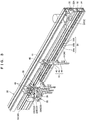
- the conveyance facility 10 includes traveling rails 30 formed along the respective conveyance paths (the first path 11, the second path 12, and the detour path 13), and the carriers 40 being supported so as to be travelable by the traveling rails 30 and supporting the bags 90 being suspended.
- Each of the traveling rails 30 is a frame material formed with an upper portion projecting more than a lower portion in the horizontal direction.
- the frame material is substantially reverse L-shaped as viewed from the side.
- the traveling rails 30 are extended along the respective conveyance paths (the first path 11, the second path 12, and the detour path 13).
- the traveling rail 30 supports a traveling wheel 41 of the carrier 40 so as to be travelable, as will be described.
- a guide groove 31 guiding an upper portion of the carrier 40, a wheel support groove 32 supporting the traveling wheel 41 of the carrier 40 so as to be travelable, an upper belt groove 33 supporting an accumulation belt 50, and a lower belt groove 34 supporting a tracking conveyance belt 52 are extended in a longitudinal direction.
- the traveling rail 30 is formed with the guide groove 31, the wheel support groove 32, the upper belt groove 33, and the lower belt groove 34, in order from the upper portion of the frame material.
- the tracking conveyance belt 52 is arranged lower than the accumulation belt 50 in the traveling rail 30.
- the accumulation belt 50 is arranged on the side of the traveling wheel 41 of the carrier 40 supported by the traveling rail 30.
- the guide groove 31 is a groove-like portion (concave portion) formed at the upper portion (portion projecting in the horizontal direction) of the traveling rail 30.
- the groove-like portion opens in a vertical direction.
- the guide groove 31 is formed at the upper portion of the traveling rail 30 so as to cover the upper portion of the traveling carrier 40.
- the guide groove 31 holds an upper side surface of the carrier 40 in the groove-like portion, and guides the upper portion of the carrier 40 along the respective conveyance paths (the first path 11, the second path 12, and the detour path 13).
- the wheel support groove 32 is a groove-like portion (concave portion) formed at an upper side surface of the traveling rail 30.
- the groove-like portion opens in the horizontal direction.
- the wheel support groove 32 can cause the traveling wheel 41 of the carrier 40 to travel.
- a lower edge portion 32A of the groove-like portion of the wheel support groove 32 is formed in accordance with the shape of the traveling wheel 41.
- the wheel support groove 32 supports the traveling wheel 41 so as to be travelable, at the edge portion 32A.
- the upper belt groove 33 is a groove-like portion (concave portion) formed at a central side surface of the traveling rail 30.
- the groove-like portion opens in the horizontal direction.
- the accumulation belt 50 can stand in the vertical direction so as to fit the upper belt groove 33.
- the upper belt groove 33 can cause the circular accumulation belt 50 to circle along a side surface of the traveling rail 30.
- the upper belt groove 33 slidably supports the accumulation belt 50 along the side surface of the traveling rail 30.
- the lower belt groove 34 is a groove-like portion (concave portion) formed at a lower side surface of the traveling rail 30.
- the groove-like portion opens in the horizontal direction.
- the tracking conveyance belt 52 can stand in the vertical direction so as to fit the lower belt groove 34.
- the lower belt groove 34 can cause the circular tracking conveyance belt 52 to circle along the side surface of the traveling rail 30.
- the lower belt groove 34 slidably supports the tracking conveyance belt 52 along the side surface of the traveling rail 30.
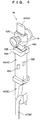
- the carrier 40 includes the traveling wheel 41 (an example of "traveling body") supported so as to be travelable with respect to the traveling rail 30, and a support 42 supporting the bag 90 being suspended.
- the traveling wheel 41 an example of "traveling body” supported so as to be travelable with respect to the traveling rail 30, and a support 42 supporting the bag 90 being suspended.
- the traveling wheel 41 includes a pair of substantially cone-shaped wheels.
- the traveling wheel 41 is turnably supported by an upper portion of the support 42.
- one wheel of the pair of wheels is placed in the wheel support groove 32 of the traveling rail 30, and is supported so as to be travelable.
- the support 42 mainly includes a body portion 43 as a main body portion of the support 42, a suspension portion 44 provided at a lower portion of the body portion 43 so as to support the bag 90 being suspended, and a head portion 45 provided at an upper portion of the body portion 43 so as to be guided by the traveling rail 30.
- the body portion 43 is composed of a lengthy plate-like member.
- a wheel support portion 43A turnably supporting the traveling wheel 41, a contact portion 43B coming into contact with the accumulation belt 50, a meshing portion 43C being meshed with the tracking conveyance belt 52, and an engaging portion 43D engaging with the first stopper 21 and the second stopper 22 of the first sending device 20 are formed.
- the wheel support portion 43A is formed at the upper portion of the body portion 43.
- a turning shaft of the traveling wheel 41 is provided orthogonally to the horizontal direction, with respect to the traveling direction of the carrier 40 traveling in the horizontal direction.
- the contact portion 43B is a block-like portion formed so as to project in the horizontal direction from both side surfaces of an upper central portion of the body portion 43. A tip end side surface of the contact portion 43B contacts with the accumulation belt 50.
- the contact portion 43B is formed with materials capable of friction transmission by the accumulation belt 50 (for example, rubber or the like).
- the meshing portion 43C is a flat plate-like convex member formed so as to project in the horizontal direction from both side surfaces of a central portion of the body portion 43.
- a tip end portion of the meshing portion 43C is meshed with the tracking conveyance belt 52.
- the tip end portion of the convex member is formed to be narrower than a base end portion of the convex member.
- the tip end portion of the convex member is also formed to be narrower than an interval between two adjacent peak portions 54A (a width of a valley portion 54B) of a concave portion 54 of the tracking conveyance belt 52, as will be described below.
- the tip end portion of the meshing portion 43C in contact with the peak portion 54A of the concave portion 54 may easily drop on the side of the valley portion 54B. Accordingly, the convex member of the meshing portion 43C may easily come into meshed contact with the valley portion 54B of the concave portion 54.
- the engaging portion 43D is a portion formed at an upper portion side of the body portion 43, and between the wheel support portion 43A and the contact portion 43B.
- a notch portion 43d is formed at a side portion in the traveling direction of the carrier 40.
- the length of the carrier 40 in the traveling direction is thereby formed to be shorter than other portions (for example, the wheel support portion 43A).
- the engaging portion 43D engages with the first stopper 21 and the second stopper 22 of the first sending device 20 at the notch portion 43d.
- the suspension portion 44 is a hook-like portion extended from the lower portion of the body portion 43.
- the suspension portion 44 can hook and support a hook portion 91 formed at an upper portion of the bag 90.
- the head portion 45 is a flat plate-like portion extended from the upper portion of the body portion 43.
- the head portion 45 is guided by the guide groove 31 of the traveling rail 30.
- the head portion 45 is formed so that a thickness in a direction orthogonal to the horizontal direction, with respect to the traveling direction of the carrier 40 traveling in the horizontal direction, is thinner than the body portion 43.
- a tip end portion of the head portion 45 is inserted into the guide groove 31. Both side surfaces of the head portion 45 are then held and guided by the guide groove 31.
- the carrier 40 travels on the traveling rail 30 through either frictional contact with the accumulation belt 50 (the friction transmission by the accumulation belt 50), or the meshed contact with the tracking conveyance belt 52 (meshing transmission by the tracking conveyance belt 52).
- the accumulation belt 50 is a circular friction transmission belt for causing the carrier 40 to travel through the friction transmission.
- the accumulation belt 50 is slidably provided in the upper belt groove 33 of the traveling rail 30, along the circumference of the traveling rail 30.
- a belt 51 is formed to be flat and contactable with a side surface of the contact portion 43B of the body portion 43 of the carrier 40.
- the accumulation belt 50 puts the belt 51 into contact with the contact portion 43B of the carrier 40.
- the belt 51 in contact with the contact portion 43B is caused to slide along the upper belt groove 33 of the traveling rail 30.
- the carrier 40 (traveling wheel 41) is thereby caused to travel.
- the tracking conveyance belt 52 is a circular meshing transmission belt for causing the carrier 40 to travel through the meshing transmission.
- the tracking conveyance belt 52 is slidably provided in the lower belt groove 34 of the traveling rail 30, along the circumference of the traveling rail 30.
- the tracking conveyance belt 52 causes the meshing portion 43C of the body portion 43 of the carrier 40 to be meshed with a belt 53.
- the belt 53 meshed with the meshing portion 43C is caused to slide along the lower belt groove 34 of the traveling rail 30.
- the carrier 40 (traveling wheel 41) is thereby caused to travel.
- a plurality of the concave portions 54 are formed on the belt 53 so as to be meshed with the meshing portion 43C of the carrier 40. As shown in FIGS.
- the concave portion 54 consists of the two peak portions 54A, and the valley portion 54B linking the adjacent peak portions 54A together.
- the peak portions 54A and the valley portions 54B are alternately and continuously formed along a moving direction (sliding direction) of the tracking conveyance belt 52.
- the meshing portion 43C of the body portion 43 of the carrier 40 is meshed between the two peak portions 54A (with the valley portion 54B) of the concave portion 54.
- the tracking conveyance belt 52 is thereby put into meshed contact with the carrier 40.
- the meshing portion 43C of one carrier 40 is meshed with one concave portion.
- the carrier 40 becomes held by the tracking conveyance belt 52.
- movement of the carrier 40 is controlled by the interval between the two peak portions 54A (the width of the valley portion 54B) of the concave portion 54.
- the accumulation belt 50 and the tracking conveyance belt 52 are arranged at different positions of the traveling rail 30. Specifically, on the horizontally arranged traveling rail 30, the tracking conveyance belt 52 is arranged at a position (the lower belt groove 34) lower than a position (the upper belt groove 33) where the accumulation belt 50 is arranged. In other words, the accumulation belt 50 is arranged so as to be frictionally contactable with the carrier 40 on a side near the traveling wheel 41 (at the contact portion 43B) in the body portion 43 of the carrier 40.
- the tracking conveyance belt 52 is arranged to be able to be meshed with the carrier 40 on a side far from the traveling wheel 41 (at the meshing portion 43C) in the body portion 43 of the carrier 40.
- the carrier 40 can travel at a stable position without jounce in conveyance in contact with the respective belts.
- the accumulation belt 50 and the tracking conveyance belt 52 are arranged at different positions from a boundary at the first sending device 20 arranged on the upstream side of the branch portion 15 of the first path 11.
- the accumulation belt 50 is arranged on the upstream side from a position where the first sending device 20 is arranged.
- the tracking conveyance belt 52 is arranged on the downstream side from the position where the first sending device 20 is arranged.
- the friction transmission by the accumulation belt 50 causes the carrier 40 to travel on the way to the first sending device 20.
- the meshing transmission by the tracking conveyance belt 52 causes the carrier 40 to travel on the downstream side from the first sending device 20.
- the swivel paths 11A and 12A, and the branch portion 14 will be described in detail.
- the swivel path 12A has the same configuration as the swivel path 11A, and thus will not be described.
- the swivel path 11A is formed as the curve section (a curved section of the conveyance path) extended from the traveling rail 30 forming a straight section of the first path 11.
- the swivel path 12A is formed as the curve section extended from the traveling rail 30 forming a straight section of the second path 12.
- the multiple carriers 40 are sent out at the predetermined intervals from a second sending device 20A provided on the upstream side.
- the multiple carriers 40 then travel on the swivel path 11A.
- the second sending device 20A has the same configuration as the first sending device 20, and thus will not be described.
- the traveling direction of the carriers 40 traveling on the swivel path 11A is changed (reversed) through the travel on the swivel path 11A.
- a pulley 70 (an example of "rotating body") rotatable along the curve section, and a guide rail 80 guiding the carriers 40 so as to be travelable along the curve section are provided.
- the pulley 70 and the guide rail 80 of the swivel path 12A have the same configurations as the pulley 70 and the guide rail 80 of the swivel path 11A.
- the pulley 70 and the guide rail 80 of the swivel path 11A will thus be described below.
- the pulley 70 is the rotating body with an outer diameter of a length similar to an interval between two traveling rails 30 forming parallel straight sections of the first path 11.
- a motor 71 is provided above the pulley 70.
- the pulley 70 is driven by the motor 71 so as to rotate.
- the pulley 70 inherits the carrier 40 conveyed from the first path 11, from the traveling rail 30.
- the pulley 70 rotates in frictional contact with the inherited carrier 40 to thereby convey the carrier 40 and reverse the traveling direction of the carrier 40.
- the accumulation belt 50 an example of "frictional contact portion
- a meshing transmission belt 72 an example of "meshing contact portion
- the accumulation belt 50 is wound on a portion of an outer peripheral surface of the pulley 70.
- the accumulation belt 50 moves along the outer peripheral surface of the pulley 70, with the rotation of the pulley 70.
- the accumulation belt 50 puts the belt 51 into contact with the contact portion 43B of the carrier 40.
- the accumulation belt 50 causes the belt 51 in contact with the contact portion 43B to move along the outer peripheral surface of the pulley 70. Thereby, the carrier 40 travels.
- the meshing transmission belt 72 is a circular belt for causing the carrier 40 to travel through the meshing transmission.
- the meshing transmission belt 72 is wound along the outer peripheral surface of the pulley 70 so as to be firmly fixed thereon.
- the meshing transmission belt 72 causes the meshing portion 43C of the body portion 43 of the carrier 40 to be meshed with a belt 73.
- the belt 73 meshed with the meshing portion 43C rotates with the pulley 70. Thereby, the carrier 40 travels.
- multiple concave portions 74 are formed on the belt 73 so as to be meshed with the meshing portion 43C of the carrier 40. As shown in FIG.
- each of the concave portions 74 consists of two peak portions 74A, and a valley portion 74B linking adjacent peak portions 74A together.
- the peak portions 74A and the valley portions 74B are alternately and continuously formed along a moving direction of the meshing transmission belt 72.
- the meshing portion 43C of the body portion 43 of the carrier 40 is meshed between the two peak portions 74A (with the valley portion 74B) of the concave portion 74.
- the meshing transmission belt 72 is thereby put into meshed contact with the carrier 40.
- the meshing portion 43C of one carrier 40 is meshed with one concave portion.
- the carrier 40 becomes held by the meshing transmission belt 72.
- the movement of the carrier 40 is controlled by an interval between the two peak portions 74A (a width of the valley portion 74B) of the concave portion 74.
- the accumulation belt 50 and the meshing transmission belt 72 are arranged at different positions of the pulley 70.
- the meshing transmission belt 72 is arranged lower than a position where the accumulation belt 50 is provided on the pulley 70.
- the accumulation belt 50 is arranged so as to be frictionally contactable with the carrier 40 on the side near the traveling wheel 41 (at the contact portion 43B) in the body portion 43 of the carrier 40.
- the meshing transmission belt 72 is arranged to be able to be meshed with the carrier 40 on the side far from the traveling wheel 41 (at the meshing portion 43C) in the body portion 43 of the carrier 40. In such a positional relationship, the accumulation belt 50 or the meshing transmission belt 72 is put into contact with the carrier 40. Thereby, the carrier 40 can travel at the stable position without jounce in the conveyance in contact with the respective belts.
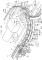
- the guide rail 80 includes a rotation guide rail 81 (an example of "traveling-body guide rail”) guiding one traveling wheel 41 (the traveling wheel 41 traveling on an inner peripheral side, with respect to the traveling direction of the carrier 40) of a pair of the traveling wheels 41 forming the carrier 40; a fixed guide rail 82 (an example of “traveling-body guide rail”) guiding the other traveling wheel 41 (the traveling wheel 41 traveling on an outer peripheral side, with respect to the traveling direction of the carrier 40) of the pair of the traveling wheels 41; an upper guide rail 83 (an example of "support guide rail”) guiding the head portion 45 of the support 42 forming the carrier 40; and a side guide rail 84 (an example of "support guide rail”) guiding the body portion 43 of the support 42 forming the carrier 40.
- a rotation guide rail 81 an example of "traveling-body guide rail” guiding one traveling wheel 41 (the traveling wheel 41 traveling on an inner peripheral side, with respect to the traveling direction of the carrier 40) of a pair of the traveling wheels 41 forming the carrier 40
- the rotation guide rail 81 is provided at an outer peripheral edge portion of an upper portion of the pulley 70.
- the rotation guide rail 81 rotates with the pulley 70.
- the rotation guide rail 81 is formed with a circular flat plate.
- a planar portion of the rotation guide rail 81 is arranged in a substantially horizontal direction so that the traveling wheel 41 can be placed thereon.
- the fixed guide rail 82 is provided along the outer peripheral side of the rotation guide rail 81.
- the fixed guide rail 82 is fixed to a not-shown facility enclosure.
- the fixed guide rail 82 is formed with a curved plate material.
- a planar portion of the fixed guide rail 82 is arranged in the substantially horizontal direction so that the traveling wheel 41 can be placed thereon. The provision of the fixed guide rail 82 can prevent the carrier 40 traveling on the swivel path 11A from tilting to an outer peripheral side of the swivel path 11A.
- the rotation guide rail 81 and the fixed guide rail 82 are arranged parallel to each other in a right-left direction with respect to the traveling direction of the carrier 40, so as to hold the body portion 43 of the carrier 40 therebetween.
- the upper guide rail 83 is provided above the rotation guide rail 81 and the fixed guide rail 82.
- the upper guide rail 83 is fixed to the not-shown facility enclosure.
- the upper guide rail 83 includes an inner peripheral side guide portion 83A and an outer peripheral side guide portion 83B.
- the inner peripheral side guide portion 83A and the outer peripheral side guide portion 83B are formed with curved plate materials.
- the inner peripheral side guide portion 83A and the outer peripheral side guide portion 83B are caused to stand in the vertical direction.
- the inner peripheral side guide portion 83A and the outer peripheral side guide portion 83B are arranged to face each other so as to keep an interval where the head portion 45 of the carrier 40 can travel.
- each of a beginning portion and an ending portion is arranged so as to be continuous with the guide groove 31 of the traveling rail 30 forming the first path 11.
- a central portion of the upper guide rail 83 is split.
- a cross branch switch 85 to be described is arranged at a space formed by the split of the upper guide rail 83.
- end portions of split portions are arranged so as to be continuous with a movable guide block 86 and lead-in guide blocks 88A and 88B of the cross branch switch 85.
- the side guide rail 84 is provided so as to face the fixed guide rail 82, below the rotation guide rail 81 and the fixed guide rail 82.
- the side guide rail 84 is fixed to the not-shown facility enclosure.
- the side guide rail 84 is formed with a curved flat plate.
- a planar portion of the side guide rail 84 is arranged in the substantially horizontal direction so that an end surface of an inner diameter side can abut the side surface of the body portion 43 of the support 42.
- the side guide rail 84 guides the side surface of the body portion 43 on the outer peripheral side of the carrier 40 traveling on the swivel path 11A.
- the side guide rail 84 guides the side surface of the body portion 43.
- the carrier 40 traveling on the swivel path 11A is thereby prevented from floating to the outer peripheral side.
- the side guide rail 84 has a function of holding the carrier 40 traveling on the swivel path 11A, onto an inner peripheral side of the swivel path 11A.
- the provision of the side guide rail 84 can prevent the meshing portion 43C of the body portion 43 of the carrier 40 traveling on the swivel path 11A, from deviation from the meshing transmission belt 72.
- the branch portion 14 is provided at an overlapping position of the swivel path 11A and the swivel path 12A.
- the carrier 40 conveyed from the first path 11 continuously travels on the swivel path 11A so as to be conveyed to the first path 11.
- the conveyance path of the carrier 40 conveyed from the first path 11 is switched from the swivel path 11A to the swivel path 12A, so that the carrier 40 is conveyed to the second path 12.
- the carrier 40 conveyed from the second path 12 continuously travels on the swivel path 12A so as to be conveyed to the second path 12.
- the conveyance path of the carrier 40 conveyed from the second path 12 is switched from the swivel path 12A to the swivel path 11A, so that the carrier 40 is conveyed to the first path 11.
- the cross branch switch 85 an example of "switching device"
- the cross branch switch 85 mainly includes the movable guide block 86 guiding the head portion 45 of the carrier 40, and a towing device 87 towing the movable guide block 86.
- the movable guide block 86 is composed of a lengthy concave member.
- a concave guide portion guiding the head portion 45 of the carrier 40 is arranged downward.
- the movable guide block 86 guides the carrier 40 at the concave guide portion so that the head portion 45 of the carrier 40 is covered from above.
- the concave guide portion is formed with a concave depth depending on the head portion 45 of the carrier 40.
- a width of the concave guide portion of the movable guide block 86 gradually narrows from an inlet side toward an outlet side.
- One end portion (end portion on the inlet side) of the movable guide block 86 is supported turnably with respect to the not-shown facility enclosure.
- the movable guide block 86 has a connecting portion 86A for connecting with an arm portion 87a of the towing device 87, on one side portion of the movable guide block 86.
- the towing device 87 mainly includes the arm portion 87a towing the movable guide block 86; a cam portion 87b driving the arm portion 87a; and a motor 87c driving the cam portion 87b.
- the arm portion 87a can move in the horizontal direction through cam drive by the motor 87c.
- One end portion of the arm portion 87a is connected to the cam portion 87b.
- the other end portion of the arm portion 87a is turnably connected to the connecting portion 86A of the movable guide block 86.
- the cam portion 87b can be driven by the motor 87c so as to turn.
- the cam portion 87b turns with the motor 87c to move the arm portion 87a in the horizontal direction.
- the motor 87c is supported by the not-shown facility enclosure.
- the motor 87c turnably supports the cam portion 87b.
- the inlet side lead-in guide block 88A is provided on the inlet side of the movable guide block 86.
- the head portion 45 of the carrier 40 is guided by the upper guide rail 83 of the swivel path 11A or the swivel path 12A.
- the inlet side lead-in guide block 88A is a guide block guiding the head portion 45 of the carrier 40 to the movable guide block 86.
- the outlet side lead-in guide block 88B is provided on the outlet side of the movable guide block 86.
- the outlet side lead-in guide block 88B is a guide block guiding the head portion 45 of the carrier 40 guided by the movable guide block 86, to the upper guide rail 83 of the swivel path 11A or the swivel path 12A.
- Guide portions 88a and 88b are formed in each of the lead-in guide blocks 88A and 88B.
- the guide portions 88a and 88b guide the head portion 45 of the carrier 40.
- the guide portions 88a and 88b are shaped with groove portions made of concave members placed downward.
- Each of the lead-in guide blocks 88A and 88B covers the head portion 45 of the carrier 40 from above, at either one guide portion of the two concave guide portions 88a and 88b.
- the lead-in guide blocks 88A and 88B thereby guide the carrier 40.
- the concave guide portions 88a and 88b are formed with the concave depth depending on the head portion 45 of the carrier 40.
- a beginning portion of the first guide portion 88a is arranged so as to be continuous with the upper guide rail 83 of the swivel path 11A.
- a beginning portion of the second guide portion 88b is arranged so as to be continuous with the upper guide rail 83 of the swivel path 12A.
- an ending portion of the first guide portion 88a is arranged so as to be continuous with the upper guide rail 83 of the swivel path 11A.
- an ending portion of the second guide portion 88b is arranged so as to be continuous with the upper guide rail 83 of the swivel path 12A.
- the lead-in guide blocks 88A and 88B are fixed to the not-shown facility enclosure.
- the head portion 45 of the support 42 of the carrier 40 is guided by the upper guide rail 83.
- the carrier 40 also travels to an inlet portion of the swivel path 11A through the friction transmission by the accumulation belt 50.
- the contact portion 43B of the support 42 is in frictional contact with the accumulation belt 50.
- the head portion 45 of the support 42 is supported by the upper guide rail 83.
- one traveling wheel 41 (the traveling wheel 41 traveling on the inner peripheral side, with respect to the traveling direction of the carrier 40) of a pair of the traveling wheels 41 is guided by the rotation guide rail 81.
- the other traveling wheel 41 (the traveling wheel 41 traveling on the outer peripheral side, with respect to the traveling direction of the carrier 40) of the pair of the traveling wheels 41 is guided by the fixed guide rail 82.
- the contact portion 43B of the support 42 is in frictional contact with the accumulation belt 50.
- the pair of traveling wheels 41 is placed on and supported by the guide rail 80 (the rotation guide rail 81 and the fixed guide rail 82).
- the meshing portion 43C of the body portion 43 is meshed with the meshing transmission belt 72 rotating with the rotation of the pulley 70.
- the carrier 40 is thereby supported by the guide rail 80, and is in contact with the accumulation belt 50 and the meshing transmission belt 72.
- the carrier 40 then travels on the swivel path 11A according to the rotation of the pulley 70. In this way, the carrier 40 travels on the swivel path 11A with conveyance power of the accumulation belt 50 and the meshing transmission belt 72.
- the cross branch switch 85 switches a guide direction of the support 42 with the movable guide block 86, and thereby switches a conveyance direction of the carrier 40.
- the cross branch switch 85 holds the movable guide block 86 so that the concave guide portion of the movable guide block 86, the guide portions 88a and 88b of the inlet side lead-in guide block 88A, and the first guide portion 88a of the outlet side lead-in guide block 88B communicate with one another.
- the head portion 45 of the support 42 of the carrier 40 guided along the upper guide rail 83 from the upstream side of the swivel path 11A is guided along the first guide portion 88a of the inlet side lead-in guide block 88A.
- the head portion 45 of the support 42 of the carrier 40 is further guided to the concave guide portion of the movable guide block 86 communicating with the first guide portion 88a of the inlet side lead-in guide block 88A. Subsequently, the head portion 45 of the support 42 of the carrier 40 is guided along the first guide portion 88a of the outlet side lead-in guide block 88B. The head portion 45 of the support 42 of the carrier 40 is thereby continuously guided to the upper guide rail 83 of the swivel path 11A on the downstream side.
- the cross branch switch 85 causes the arm portion 87a of the towing device 87 to move in the horizontal direction.
- the cross branch switch 85 thereby tows the movable guide block 86 in a direction orthogonal to the horizontal direction.
- the other end portion (end portion on the outlet side) of the movable guide block 86 turns toward the upper guide rail 83 of the swivel path 12A on the downstream side.
- the concave guide portion of the movable guide block 86, the guide portions 88a and 88b of the inlet side lead-in guide block 88A, and the second guide portion 88b of the outlet side lead-in guide block 88B communicate with one another.
- the head portion 45 of the support 42 of the carrier 40 guided along the upper guide rail 83 from the upstream side of the swivel path 11A is guided along the first guide portion 88a of the inlet side lead-in guide block 88A.
- the head portion 45 of the support 42 of the carrier 40 is further guided to the concave guide portion of the movable guide block 86 communicating with the first guide portion 88a of the inlet side lead-in guide block 88A.
- the head portion 45 of the support 42 of the carrier 40 is guided along the second guide portion 88b of the outlet side lead-in guide block 88B.
- the head portion 45 of the support 42 of the carrier 40 is thereby directed to the upper guide rail 83 of the swivel path 12A on the downstream side.
- the carrier 40 is caused to travel on the swivel paths 11A and 12A (curve sections) with the both traveling wheels 41 being guided by the guide rail 80.
- the carrier 40 thus does not need to separately include an engaging portion for the pulley 70.
- the configuration of the carrier 40 can thus be simplified.
- the carrier 40 when the carrier 40 transfers the traveling section from the straight section of the first path 11 (second path 12) to the curve section of the swivel path 11A (swivel path 12A), the carrier 40 itself does not need to be synchronized to the rotation of the pulley 70.
- the conveyance of the carrier 40 can thus be easily controlled.
- strict adjustment of an installation height of the pulley 70 is not required in accordance with the position of the traveling rails 30 (height of the conveyed carrier 40). Installation of the pulley 70 can thus be simplified.
- the carrier 40 transfers the traveling section from the straight section of the first path 11 (second path 12) to the curve section of the swivel path 11A (swivel path 12A), or when the carrier 40 transfers the traveling section from the curve section of the swivel path 11A (swivel path 12A) to the curve section of the swivel path 12A (swivel path 11A), the support 42 of the carrier 40 does not engage (mate) with the pulley 70 itself. Generation of friction between the support 42 of the carrier 40 and the pulley 70 can thus be prevented.
- the carrier 40 is caused to travel on the swivel paths 11A and 12A (curve sections) with the both traveling wheels 41 being guided by the guide rail 80.
- the carrier 40 can thus be prevented from dropout from the guide rail 80 due to swing of the conveyed bag 90 or the like.
- the carrier 40 meshed with the meshing transmission belt 72 travels on the swivel path 11A.
- the multiple carriers 40 can thus be caused to travel along the swivel path 11A (curve section) while the predetermined intervals are kept. If the carrier 40 is conveyed only through the friction transmission by the accumulation belt 50, the carrier 40 may be misaligned with the accumulation belt 50 during the conveyance of the carrier 40. Accordingly, conveyance pitch of the carrier 40 needs to be increased when the carrier 40 is caused to travel on the swivel paths 11A and 12A. If the meshing transmission by the meshing transmission belt 72 is also employed, however, such misalignment does not occur. The conveyance pitch of the carrier 40 can thus be reduced when the carrier 40 is caused to travel on the swivel paths 11A and 12A. Consequently, capability of the conveyance of the carrier 40 in the conveyance facility 10 can be improved.
- the meshed contact with the carrier 40 is performed lower than the frictional contact with the carrier 40.
- the carrier 40 can thus be caused to stably travel on the swivel paths 11A and 12A (curve sections).
- the guide for a pair of the traveling wheels 41 is mutually switched between the rotation guide rail 81 and the fixed guide rail 82.
- the carrier 40 can be prevented from the dropout from the guide rail 80 due to the swing of the conveyed bag 90 or the like.
- the article conveyed in the conveyance facility 10 is the bag 90.
- the article is, however, not limited thereto, and may be any article capable of being suspended by the carrier 40.
- the meshing portion 43C of the carrier 40 is composed of the flat plate-like convex member.
- the meshing portion 43C is, however, not limited thereto, and may be composed of a concave member, for example, as long as the meshing between the tracking conveyance belt 52 and the meshing transmission belt 72 is possible.
- the peak portion 54A of the concave portion 54 of the tracking conveyance belt 52, and the peak portion 74A of the concave portion 74 of the meshing transmission belt 72 are meshed with the concave member of the meshing portion 43C.
- one meshing portion 43C is provided on the body portion 43 of the carrier 40.
- the meshing portion 43C is, however, not limited thereto. Multiple meshing portions 43C may be provided on the body portion 43, as long as the meshing between the tracking conveyance belt 52 and the meshing transmission belt 72 is possible.
- the movable guide block 86 is towed by the towing device 87 so as to switch the guide direction of the support 42 by the movable guide block 86.
- This configuration is, however, not limited thereto.
- a turning shaft turnably supporting the movable guide block 86 may be directly turned by a drive source such as a motor.
- an electric actuator 87A may mainly include the arm portion 87a towing the movable guide block 86; and a main body portion 87d causing the arm portion 87a to perform expansion and contraction movement.
- the electric actuator 87A may be employed as the towing device 87 in the cross branch switch 85.
- the arm portion 87a can perform the expansion and contraction movement in the horizontal direction with respect to the main body portion 87d.
- a tip end of the arm portion 87a is turnably connected to the connecting portion 86A of the movable guide block 86.
- the main body portion 87d is supported turnably with respect to the not-shown facility enclosure, and movably supports the arm portion 87a.
- the main body portion 87d includes a not-shown motor for moving the arm portion 87a. The motor is driven to cause the arm portion 87a to perform the expansion and contraction movement.
Landscapes
- Engineering & Computer Science (AREA)
- Mechanical Engineering (AREA)
- Branching, Merging, And Special Transfer Between Conveyors (AREA)
- Chain Conveyers (AREA)
- Specific Conveyance Elements (AREA)
- Framework For Endless Conveyors (AREA)
Abstract
Description
- The present invention relates to a conveyance facility for conveying articles along a conveyance path, in particular to a conveyance facility for suspended conveyance of the articles.
- A conventional conveyance facility for suspended conveyance of articles is shown in
WO01/068482 WO01/068482 - The suspended conveyor device shown in
WO01/068482 - In the conveyance facility shown in
WO01/068482 - The support itself needs to be synchronized to the rotation of the deflection drum for the engagement of the engaging portion (groove) of the support with the conveyor flange of the deflection drum. Unfortunately, conveyance control of the support thus becomes complex. In addition, strict adjustment of an installation height of the deflection drum is required in accordance with positions of the traveling rails (a height of the conveyed support). Such strict adjustment causes difficult installation of the deflection drum.
- Unfortunately, in the inheritance (transfer) of the support traveling on the traveling rails by the deflection drum (rotating body), the engaging portion (groove) of the support is caused to engage with the conveyor flange of the deflection drum. The engagement thus generates friction between the engaging portion (groove) of the support and the conveyor flange (deflection drum), in the transfer of the conveyance unit to the deflection drum.
- An object of the present invention is to provide a conveyance facility capable of simplifying the configuration of the conveyance unit, the control of the conveyance with the conveyance unit, and the installation of the rotating body, and also capable of preventing the generation of the friction between the support of the conveyance unit and the rotating body.
- Problems to be solved by the present invention have been described. Solutions to the problems will be described next.
- A conveyance facility of the present invention is a conveyance facility for conveying an article along a conveyance path, including: a conveyance unit including a pair of traveling bodies traveling on the conveyance path, and a support traveling with the pair of traveling bodies and supporting the article being suspended, the conveyance unit conveying the article along the conveyance path, wherein the conveyance path includes a straight section, and a curve section extended from the straight section, wherein the curve section includes: a rotating body rotatable along the curve section and in frictional contact with the support; a traveling-body guide rail guiding the pair of traveling bodies so as to be travelable along the curve section; and a support guide rail guiding the support along the curve section, and wherein the traveling-body guide rail includes: a rotation guide rail guiding one traveling body of the pair of traveling bodies, and rotating with the rotating body; and a fixed guide rail guiding another traveling body of the pair of traveling bodies, and being provided along the rotation guide rail.
- In the aforementioned configuration, the support of the conveyance unit traveling on the curve section is guided by the support guide rail. In the aforementioned configuration, one traveling body of the pair of traveling bodies is guided by the rotation guide rail, and the other traveling body of the pair of traveling bodies is guided by the fixed guide rail.
- Furthermore, the support guide rail includes an upper guide rail guiding a head portion of the support; and a side guide rail guiding a body portion of the support.
- In the aforementioned configuration, the head portion of the support of the conveyance unit traveling on the curve section is guided by the upper guide rail. In the aforementioned configuration, the body portion of the support of the conveyance unit traveling on the curve section is guided by the side guide rail.
- Furthermore, the rotating body includes a meshing contact portion being meshed with the support.
- In the aforementioned configuration, the rotating body meshed with the support rotates along the curve section.
- Furthermore, the rotating body includes a frictional contact portion coming into frictional contact with the support; and a meshing contact portion being meshed with the support, and the meshing contact portion is provided lower than a position where the frictional contact portion is provided in the rotating body.
- In the aforementioned configuration, meshed contact with the support is performed lower than the frictional contact with the support.
- Furthermore, the conveyance path includes a first conveyance path including the curve section, and a second conveyance path provided independently from the first conveyance path and including the curve section; the conveyance facility includes a switching device capable of switching the conveyance path of the conveyance unit traveling on the curve section of the first conveyance path, to the curve section of the second conveyance path, and capable of switching the conveyance path of the conveyance unit traveling on the curve section of the second conveyance path, to the curve section of the first conveyance path; and when the switching device switches the conveyance path of the conveyance unit, the switching device switches the guide for the traveling body guided by the rotation guide rail, to the guide by the fixed guide rail, and switches the guide for the traveling body guided by the fixed guide rail, to the guide by the rotation guide rail.
- In the aforementioned configuration, the guide for the traveling body guided by the rotation guide rail is switched to the guide by the fixed guide rail. The guide for the traveling body guided by the fixed guide rail is switched to the guide by the rotation guide rail. The conveyance path of the conveyance unit is thereby switched.
- According to the conveyance facility of the present invention, the conveyance unit is caused to travel on the curve section with both traveling bodies being guided by the guide rail. The conveyance unit thus does not need to separately include the engaging portion for the rotating body. The configuration of the conveyance unit can thus be simplified.
- When the conveyance unit transfers a traveling section from the straight section to the curve section of the conveyance path, the conveyance unit itself does not need to be synchronized to the rotation of the rotating body. The conveyance of the conveyance unit can thus be easily controlled. In addition, the strict adjustment of the installation height of the rotating body is not required in accordance with the height of the conveyed support. The installation of the rotating body can thus be simplified.
- When the conveyance unit transfers the traveling section from the straight section to the curve section of the conveyance path, the support of the conveyance unit does not engage (mate) with the rotating body itself. The generation of the friction between the support and the rotating body can thus be prevented.
-
-
FIG. 1 is a general perspective view of a conveyance facility according to the present invention; -
FIG. 2A is a plan view showing an outline of operations of first and second sending devices of the same conveyance facility in a case where a first stopper is moved forward; -
FIG. 2B is a plan view showing the outline of the operations of the first and second sending devices of the same conveyance facility in a case where the first stopper is moved backward and a second stopper is moved forward; -
FIG. 2C is a plan view showing the outline of the operations of the first and second sending devices of the same conveyance facility in a case where the second stopper is moved backward and the first stopper is moved forward; -
FIG. 3 is a perspective view of a traveling rail of the same conveyance facility; -
FIG. 4 is a perspective view of a carrier of the same conveyance facility; -
FIG. 5 is a cross-sectional view of the traveling rail of the same conveyance facility; -
FIG. 6 is a schematic plan and cross-sectional view showing the carrier and a tracking conveyance belt of the same conveyance facility when the carrier is meshed with the tracking conveyance belt; -
FIG. 7 is a perspective view in the vicinity of a cross joint branch portion of the same conveyance facility; -
FIG. 8 is a schematic plan and cross-sectional view showing the carrier and a pulley of the same conveyance facility when the carrier is conveyed by the pulley; -
FIG. 9A is a plan view showing operations of a cross branch switch of the same conveyance facility in a case where a conveyance path of the carrier is a first circulation path; -
FIG. 9B is a plan view showing the operations of the cross branch switch of the same conveyance facility in a case where the conveyance path of the carrier is changed from the first circulation path to a second circulation path; -
FIG. 10 is a perspective view in the vicinity of a cross joint branch portion according to another example of the same conveyance facility; -
FIG. 11A is a plan view showing operations of a cross branch switch according to the other example of the same conveyance facility in a case where a conveyance path of a carrier is a first circulation path; and -
FIG. 11B is a plan view showing the operations of the cross branch switch according to the other example of the same conveyance facility in a case where the conveyance path of the carrier is changed from the first circulation path to a second circulation path. - A
conveyance facility 10 according to the present invention will be described. The present invention is not limited to theconveyance facility 10 to be shown below. - As shown in
FIG. 1 , theconveyance facility 10 is a suspended conveyance facility for suspended conveyance of bags 90 (an example of "article") containing goods. Theconveyance facility 10 includes a first path 11 (an example of "conveyance path" and "first conveyance path") and a second path 12 (an example of "conveyance path" and "second conveyance path") for circularly conveying thebags 90, as well as a detour path 13 (an example of "conveyance path") branching from somewhere in the middle of thefirst path 11 and joining thesecond path 12. - The
first path 11 and thesecond path 12 include loop-like conveyance paths. Thefirst path 11 and thesecond path 12 haveswivel paths first path 11 and thesecond path 12 are serially arranged so that theswivel path 11A and theswivel path 12A on the respective ones of the end portions face each other. Abranch portion 14 is provided at a joint section between thefirst path 11 and the second path 12 (a portion where theswivel path 11A and theswivel path 12A face each other). - The
branch portion 14 keeps thebags 90 being circularly conveyed on thefirst path 11 so as to be circularly conveyed on thefirst path 11. Alternatively, thebranch portion 14 causes thebags 90 being circularly conveyed on thefirst path 11 to be conveyed on thesecond path 12 through intersection of thebranch portion 14. Thebranch portion 14 keeps thebags 90 being circularly conveyed on thesecond path 12 so as to be circularly conveyed on thesecond path 12. Alternatively, thebranch portion 14 causes thebags 90 being circularly conveyed on thesecond path 12 to be conveyed on thefirst path 11 through the intersection of thebranch portion 14. Theswivel paths branch portion 14 will be described later. - The
detour path 13 is a conveyance path for causing thebags 90 conveyed on thefirst path 11 to detour without thebranch portion 14 so as to join thesecond path 12. A beginning portion of thedetour path 13 branches somewhere in the middle of thefirst path 11. An ending portion of thedetour path 13 joins thesecond path 12. - A
branch portion 15 is provided at the beginning portion of the detour path 13 (a connecting portion between thedetour path 13 and the first path 11). Thebranch portion 15 is a portion where thedetour path 13 branches from somewhere in the middle of thefirst path 11. Thebranch portion 15 keeps thebags 90 conveyed on thefirst path 11 so as to be conveyed on thefirst path 11. Alternatively, thebranch portion 15 causes some of thebags 90 conveyed on thefirst path 11 to branch from thefirst path 11 to thedetour path 13 for conveyance. - A
joint portion 16 is provided at the ending portion of the detour path 13 (a connecting portion between thedetour path 13 and the second path 12). Thejoint portion 16 is a portion where thedetour path 13 joins thesecond path 12. Thejoint portion 16 keeps thebags 90 conveyed on thesecond path 12 so as to be conveyed on thesecond path 12. Alternatively, thejoint portion 16 causes thebags 90 conveyed on thedetour path 13 to join thesecond path 12. - On the
first path 11, afirst sending device 20 is provided on an upstream side of thebranch portion 15. Thefirst sending device 20 is a device for sending out multiple carriers 40 (an example of "conveyance unit") traveling with thebags 90 being suspended, at predetermined intervals. Thefirst sending device 20 causes themultiple carriers 40 continuously traveling toward thebranch portion 15 to stop once, and causes theadjacent carriers 40 to sequentially travel at the predetermined intervals. As shown inFIGS. 2A to 2C , the first sendingdevice 20 includes afirst stopper 21 and asecond stopper 22 for stopping thecarriers 40, and acam mechanism 23 for moving thefirst stopper 21 and thesecond stopper 22. - The
first stopper 21 and thesecond stopper 22 are lengthy members extended orthogonally to a horizontal direction, with respect to a traveling direction of thecarriers 40 traveling in the horizontal direction. Thefirst stopper 21 and thesecond stopper 22 are driven by thecam mechanism 23 so as to move outward and backward with respect to the horizontal direction. Tip end portions of thefirst stopper 21 and thesecond stopper 22 move forward with respect to the horizontal direction so as to abut a front surface of each of thecarriers 40 in the traveling direction to stop thecarrier 40. The tip end portions of thefirst stopper 21 and thesecond stopper 22 move backward with respect to the horizontal direction so as to cancel the stop of thecarrier 40 caused by the tip end portions. Thefirst stopper 21 is arranged closer to an upstream side of the first sendingdevice 20 than thesecond stopper 22. - The
cam mechanism 23 includes acam body 23A causing thefirst stopper 21 and thesecond stopper 22 to alternately move outward and backward, anarm 23B swinging thecam body 23A, and adrive motor 23C driving thearm 23B. Thecam mechanism 23 drives thedrive motor 23C to operate thearm 23B so as to swing thecam body 23A. Thefirst stopper 21 and thesecond stopper 22 thereby alternately move outward and backward with respect to the horizontal direction. - The
first sending device 20 causes thefirst stopper 21 and thesecond stopper 22 to alternately move outward and backward, and shifts timings of thecarriers 40 passing through the first sendingdevice 20, so as to have the predetermined intervals between theadjacent carriers 40. Specifically, as shown inFIG. 2A , the tip end portion of thefirst stopper 21 abuts the front surface of thecarrier 40 traveling from the upstream side of the first sendingdevice 20, in the traveling direction. Thecarrier 40 traveling from the upstream side of the first sendingdevice 20 is thereby stopped by thefirst stopper 21. As shown inFIG. 2B , thecam mechanism 23 is driven to cause thefirst stopper 21 to move backward and also cause thesecond stopper 22 to move forward. Thecarrier 40 stopped by thefirst stopper 21 thereby travels to a downstream side, and is stopped again by thesecond stopper 22. As shown inFIG. 2C , at a timing of asubsequent carrier 40 arriving at thefirst stopper 21, thecam mechanism 23 is driven to cause thefirst stopper 21 to move forward and also cause thesecond stopper 22 to move backward. Thecarrier 40 stopped by thesecond stopper 22 thereby travels to the downstream side, and thesubsequent carrier 40 is stopped by thefirst stopper 21. In this way, the alternate movement of thefirst stopper 21 and thesecond stopper 22 causes only onecarrier 40 to pass between thefirst stopper 21 and thesecond stopper 22. The adjacent carriers 40 (bags 90) thereby travel at the predetermined intervals. - As shown in
FIG. 1 , abranch unit 60 is provided at thebranch portion 15 of thefirst path 11. Thebranch unit 60 is a device for switching the conveyance path of thebags 90 conveyed on thefirst path 11, to thedetour path 13. Thebranch unit 60 includes abranch device 61 for switching the conveyance path of thecarriers 40. Thebranch unit 60 actuates thebranch device 61 to direct thecarriers 40 traveling on thefirst path 11, to thedetour path 13. The conveyance path of the bags 90 (carriers 40) conveyed from thefirst path 11 is thereby switched to thedetour path 13. - As shown in
FIGS. 1 ,3 and4 , theconveyance facility 10 includes travelingrails 30 formed along the respective conveyance paths (thefirst path 11, thesecond path 12, and the detour path 13), and thecarriers 40 being supported so as to be travelable by the travelingrails 30 and supporting thebags 90 being suspended. - Each of the traveling rails 30 is a frame material formed with an upper portion projecting more than a lower portion in the horizontal direction. The frame material is substantially reverse L-shaped as viewed from the side. The traveling rails 30 are extended along the respective conveyance paths (the
first path 11, thesecond path 12, and the detour path 13). The travelingrail 30 supports a travelingwheel 41 of thecarrier 40 so as to be travelable, as will be described. In the travelingrail 30, aguide groove 31 guiding an upper portion of thecarrier 40, awheel support groove 32 supporting the travelingwheel 41 of thecarrier 40 so as to be travelable, anupper belt groove 33 supporting anaccumulation belt 50, and alower belt groove 34 supporting a trackingconveyance belt 52 are extended in a longitudinal direction. The travelingrail 30 is formed with theguide groove 31, thewheel support groove 32, theupper belt groove 33, and thelower belt groove 34, in order from the upper portion of the frame material. According to such a configuration of the travelingrail 30, the trackingconveyance belt 52 is arranged lower than theaccumulation belt 50 in the travelingrail 30. Also, theaccumulation belt 50 is arranged on the side of the travelingwheel 41 of thecarrier 40 supported by the travelingrail 30. - The
guide groove 31 is a groove-like portion (concave portion) formed at the upper portion (portion projecting in the horizontal direction) of the travelingrail 30. The groove-like portion opens in a vertical direction. Theguide groove 31 is formed at the upper portion of the travelingrail 30 so as to cover the upper portion of the travelingcarrier 40. Theguide groove 31 holds an upper side surface of thecarrier 40 in the groove-like portion, and guides the upper portion of thecarrier 40 along the respective conveyance paths (thefirst path 11, thesecond path 12, and the detour path 13). - The
wheel support groove 32 is a groove-like portion (concave portion) formed at an upper side surface of the travelingrail 30. The groove-like portion opens in the horizontal direction. Thewheel support groove 32 can cause the travelingwheel 41 of thecarrier 40 to travel. Alower edge portion 32A of the groove-like portion of thewheel support groove 32 is formed in accordance with the shape of the travelingwheel 41. Thewheel support groove 32 supports the travelingwheel 41 so as to be travelable, at theedge portion 32A. - The
upper belt groove 33 is a groove-like portion (concave portion) formed at a central side surface of the travelingrail 30. The groove-like portion opens in the horizontal direction. Theaccumulation belt 50 can stand in the vertical direction so as to fit theupper belt groove 33. Theupper belt groove 33 can cause thecircular accumulation belt 50 to circle along a side surface of the travelingrail 30. Theupper belt groove 33 slidably supports theaccumulation belt 50 along the side surface of the travelingrail 30. - The
lower belt groove 34 is a groove-like portion (concave portion) formed at a lower side surface of the travelingrail 30. The groove-like portion opens in the horizontal direction. The trackingconveyance belt 52 can stand in the vertical direction so as to fit thelower belt groove 34. Thelower belt groove 34 can cause the circulartracking conveyance belt 52 to circle along the side surface of the travelingrail 30. Thelower belt groove 34 slidably supports the trackingconveyance belt 52 along the side surface of the travelingrail 30. - As shown in
FIGS. 3 to 5 , thecarrier 40 includes the traveling wheel 41 (an example of "traveling body") supported so as to be travelable with respect to the travelingrail 30, and asupport 42 supporting thebag 90 being suspended. - The traveling
wheel 41 includes a pair of substantially cone-shaped wheels. The travelingwheel 41 is turnably supported by an upper portion of thesupport 42. In the travelingwheel 41, one wheel of the pair of wheels is placed in thewheel support groove 32 of the travelingrail 30, and is supported so as to be travelable. - The
support 42 mainly includes abody portion 43 as a main body portion of thesupport 42, asuspension portion 44 provided at a lower portion of thebody portion 43 so as to support thebag 90 being suspended, and ahead portion 45 provided at an upper portion of thebody portion 43 so as to be guided by the travelingrail 30. - As shown in
FIGS. 4 and5 , thebody portion 43 is composed of a lengthy plate-like member. In thebody portion 43, awheel support portion 43A turnably supporting the travelingwheel 41, acontact portion 43B coming into contact with theaccumulation belt 50, a meshingportion 43C being meshed with the trackingconveyance belt 52, and an engagingportion 43D engaging with thefirst stopper 21 and thesecond stopper 22 of the first sendingdevice 20 are formed. - The
wheel support portion 43A is formed at the upper portion of thebody portion 43. In thewheel support portion 43A, a turning shaft of the travelingwheel 41 is provided orthogonally to the horizontal direction, with respect to the traveling direction of thecarrier 40 traveling in the horizontal direction. - The
contact portion 43B is a block-like portion formed so as to project in the horizontal direction from both side surfaces of an upper central portion of thebody portion 43. A tip end side surface of thecontact portion 43B contacts with theaccumulation belt 50. Thecontact portion 43B is formed with materials capable of friction transmission by the accumulation belt 50 (for example, rubber or the like). - The meshing
portion 43C is a flat plate-like convex member formed so as to project in the horizontal direction from both side surfaces of a central portion of thebody portion 43. A tip end portion of the meshingportion 43C is meshed with the trackingconveyance belt 52. As shown inFIG. 6 , in the meshingportion 43C, the tip end portion of the convex member is formed to be narrower than a base end portion of the convex member. The tip end portion of the convex member is also formed to be narrower than an interval between twoadjacent peak portions 54A (a width of avalley portion 54B) of aconcave portion 54 of the trackingconveyance belt 52, as will be described below. With this formation of the meshingportion 43C, in the meshing with the trackingconveyance belt 52, the tip end portion of the meshingportion 43C in contact with thepeak portion 54A of theconcave portion 54 may easily drop on the side of thevalley portion 54B. Accordingly, the convex member of the meshingportion 43C may easily come into meshed contact with thevalley portion 54B of theconcave portion 54. - As shown in
FIG. 4 , the engagingportion 43D is a portion formed at an upper portion side of thebody portion 43, and between thewheel support portion 43A and thecontact portion 43B. In the engagingportion 43D, anotch portion 43d is formed at a side portion in the traveling direction of thecarrier 40. The length of thecarrier 40 in the traveling direction is thereby formed to be shorter than other portions (for example, thewheel support portion 43A). The engagingportion 43D engages with thefirst stopper 21 and thesecond stopper 22 of the first sendingdevice 20 at thenotch portion 43d. - As shown in
FIGS. 3 and4 , thesuspension portion 44 is a hook-like portion extended from the lower portion of thebody portion 43. Thesuspension portion 44 can hook and support ahook portion 91 formed at an upper portion of thebag 90. - The
head portion 45 is a flat plate-like portion extended from the upper portion of thebody portion 43. Thehead portion 45 is guided by theguide groove 31 of the travelingrail 30. Thehead portion 45 is formed so that a thickness in a direction orthogonal to the horizontal direction, with respect to the traveling direction of thecarrier 40 traveling in the horizontal direction, is thinner than thebody portion 43. A tip end portion of thehead portion 45 is inserted into theguide groove 31. Both side surfaces of thehead portion 45 are then held and guided by theguide groove 31. - As shown in
FIGS. 3 and5 , thecarrier 40 travels on the travelingrail 30 through either frictional contact with the accumulation belt 50 (the friction transmission by the accumulation belt 50), or the meshed contact with the tracking conveyance belt 52 (meshing transmission by the tracking conveyance belt 52). - The
accumulation belt 50 is a circular friction transmission belt for causing thecarrier 40 to travel through the friction transmission. Theaccumulation belt 50 is slidably provided in theupper belt groove 33 of the travelingrail 30, along the circumference of the travelingrail 30. In theaccumulation belt 50, abelt 51 is formed to be flat and contactable with a side surface of thecontact portion 43B of thebody portion 43 of thecarrier 40. Theaccumulation belt 50 puts thebelt 51 into contact with thecontact portion 43B of thecarrier 40. Thebelt 51 in contact with thecontact portion 43B is caused to slide along theupper belt groove 33 of the travelingrail 30. The carrier 40 (traveling wheel 41) is thereby caused to travel. - The tracking
conveyance belt 52 is a circular meshing transmission belt for causing thecarrier 40 to travel through the meshing transmission. The trackingconveyance belt 52 is slidably provided in thelower belt groove 34 of the travelingrail 30, along the circumference of the travelingrail 30. The trackingconveyance belt 52 causes the meshingportion 43C of thebody portion 43 of thecarrier 40 to be meshed with abelt 53. Thebelt 53 meshed with the meshingportion 43C is caused to slide along thelower belt groove 34 of the travelingrail 30. The carrier 40 (traveling wheel 41) is thereby caused to travel. In the trackingconveyance belt 52, a plurality of theconcave portions 54 are formed on thebelt 53 so as to be meshed with the meshingportion 43C of thecarrier 40. As shown inFIGS. 3 and6 , theconcave portion 54 consists of the twopeak portions 54A, and thevalley portion 54B linking theadjacent peak portions 54A together. For theconcave portions 54, thepeak portions 54A and thevalley portions 54B are alternately and continuously formed along a moving direction (sliding direction) of the trackingconveyance belt 52. The meshingportion 43C of thebody portion 43 of thecarrier 40 is meshed between the twopeak portions 54A (with thevalley portion 54B) of theconcave portion 54. The trackingconveyance belt 52 is thereby put into meshed contact with thecarrier 40. In other words, the meshingportion 43C of onecarrier 40 is meshed with one concave portion. Thereby, thecarrier 40 becomes held by the trackingconveyance belt 52. When thebelt 53 slides, movement of thecarrier 40 is controlled by the interval between the twopeak portions 54A (the width of thevalley portion 54B) of theconcave portion 54. - The
accumulation belt 50 and the trackingconveyance belt 52 are arranged at different positions of the travelingrail 30. Specifically, on the horizontally arranged travelingrail 30, the trackingconveyance belt 52 is arranged at a position (the lower belt groove 34) lower than a position (the upper belt groove 33) where theaccumulation belt 50 is arranged. In other words, theaccumulation belt 50 is arranged so as to be frictionally contactable with thecarrier 40 on a side near the traveling wheel 41 (at thecontact portion 43B) in thebody portion 43 of thecarrier 40. The trackingconveyance belt 52 is arranged to be able to be meshed with thecarrier 40 on a side far from the traveling wheel 41 (at the meshingportion 43C) in thebody portion 43 of thecarrier 40. In such arrangements, for the frictional contact of thecarrier 40 with theaccumulation belt 50, the side (contact portion 43B) near the travelingwheel 41 in thecarrier 40 contacts with theaccumulation belt 50. For the meshing between thecarrier 40 and the trackingconveyance belt 52, the side (meshingportion 43C) far from the travelingwheel 41 in thecarrier 40 contacts with the trackingconveyance belt 52. Accordingly, thecarrier 40 can travel at a stable position without jounce in conveyance in contact with the respective belts. - As shown in
FIG. 3 , theaccumulation belt 50 and the trackingconveyance belt 52 are arranged at different positions from a boundary at the first sendingdevice 20 arranged on the upstream side of thebranch portion 15 of thefirst path 11. Specifically, theaccumulation belt 50 is arranged on the upstream side from a position where the first sendingdevice 20 is arranged. The trackingconveyance belt 52 is arranged on the downstream side from the position where the first sendingdevice 20 is arranged. In other words, the friction transmission by theaccumulation belt 50 causes thecarrier 40 to travel on the way to the first sendingdevice 20. The meshing transmission by the trackingconveyance belt 52 causes thecarrier 40 to travel on the downstream side from the first sendingdevice 20. - The
swivel paths branch portion 14 will be described in detail. Theswivel path 12A has the same configuration as theswivel path 11A, and thus will not be described. - As shown in
FIGS. 1 and7 , theswivel path 11A is formed as the curve section (a curved section of the conveyance path) extended from the travelingrail 30 forming a straight section of thefirst path 11. Similarly, theswivel path 12A is formed as the curve section extended from the travelingrail 30 forming a straight section of thesecond path 12. - The
multiple carriers 40 are sent out at the predetermined intervals from asecond sending device 20A provided on the upstream side. Themultiple carriers 40 then travel on theswivel path 11A. Thesecond sending device 20A has the same configuration as the first sendingdevice 20, and thus will not be described. The traveling direction of thecarriers 40 traveling on theswivel path 11A is changed (reversed) through the travel on theswivel path 11A. - As shown in
FIG. 7 , at each of the curve section forming theswivel path 11A and the curve section forming theswivel path 12A, a pulley 70 (an example of "rotating body") rotatable along the curve section, and aguide rail 80 guiding thecarriers 40 so as to be travelable along the curve section are provided. Thepulley 70 and theguide rail 80 of theswivel path 12A have the same configurations as thepulley 70 and theguide rail 80 of theswivel path 11A. Thepulley 70 and theguide rail 80 of theswivel path 11A will thus be described below. - The
pulley 70 is the rotating body with an outer diameter of a length similar to an interval between two travelingrails 30 forming parallel straight sections of thefirst path 11. Amotor 71 is provided above thepulley 70. Thepulley 70 is driven by themotor 71 so as to rotate. Thepulley 70 inherits thecarrier 40 conveyed from thefirst path 11, from the travelingrail 30. Thepulley 70 rotates in frictional contact with the inheritedcarrier 40 to thereby convey thecarrier 40 and reverse the traveling direction of thecarrier 40. As shown inFIGS. 7 and8 , the accumulation belt 50 (an example of "frictional contact portion") and a meshing transmission belt 72 (an example of "meshing contact portion") are provided along an outer peripheral side surface of thepulley 70. - The
accumulation belt 50 is wound on a portion of an outer peripheral surface of thepulley 70. Theaccumulation belt 50 moves along the outer peripheral surface of thepulley 70, with the rotation of thepulley 70. Theaccumulation belt 50 puts thebelt 51 into contact with thecontact portion 43B of thecarrier 40. Theaccumulation belt 50 causes thebelt 51 in contact with thecontact portion 43B to move along the outer peripheral surface of thepulley 70. Thereby, thecarrier 40 travels. - The meshing
transmission belt 72 is a circular belt for causing thecarrier 40 to travel through the meshing transmission. The meshingtransmission belt 72 is wound along the outer peripheral surface of thepulley 70 so as to be firmly fixed thereon. The meshingtransmission belt 72 causes the meshingportion 43C of thebody portion 43 of thecarrier 40 to be meshed with abelt 73. In the meshingtransmission belt 72, thebelt 73 meshed with the meshingportion 43C rotates with thepulley 70. Thereby, thecarrier 40 travels. In the meshingtransmission belt 72, multipleconcave portions 74 are formed on thebelt 73 so as to be meshed with the meshingportion 43C of thecarrier 40. As shown inFIG. 7 , each of theconcave portions 74 consists of twopeak portions 74A, and avalley portion 74B linkingadjacent peak portions 74A together. For theconcave portions 74, thepeak portions 74A and thevalley portions 74B are alternately and continuously formed along a moving direction of the meshingtransmission belt 72. The meshingportion 43C of thebody portion 43 of thecarrier 40 is meshed between the twopeak portions 74A (with thevalley portion 74B) of theconcave portion 74. The meshingtransmission belt 72 is thereby put into meshed contact with thecarrier 40. In other words, the meshingportion 43C of onecarrier 40 is meshed with one concave portion. Thereby, thecarrier 40 becomes held by the meshingtransmission belt 72. When thebelt 73 moves, the movement of thecarrier 40 is controlled by an interval between the twopeak portions 74A (a width of thevalley portion 74B) of theconcave portion 74. - The
accumulation belt 50 and the meshingtransmission belt 72 are arranged at different positions of thepulley 70. Specifically, the meshingtransmission belt 72 is arranged lower than a position where theaccumulation belt 50 is provided on thepulley 70. In other words, theaccumulation belt 50 is arranged so as to be frictionally contactable with thecarrier 40 on the side near the traveling wheel 41 (at thecontact portion 43B) in thebody portion 43 of thecarrier 40. The meshingtransmission belt 72 is arranged to be able to be meshed with thecarrier 40 on the side far from the traveling wheel 41 (at the meshingportion 43C) in thebody portion 43 of thecarrier 40. In such a positional relationship, theaccumulation belt 50 or the meshingtransmission belt 72 is put into contact with thecarrier 40. Thereby, thecarrier 40 can travel at the stable position without jounce in the conveyance in contact with the respective belts. - As shown in
FIGS. 7 and8 , theguide rail 80 includes a rotation guide rail 81 (an example of "traveling-body guide rail") guiding one traveling wheel 41 (the travelingwheel 41 traveling on an inner peripheral side, with respect to the traveling direction of the carrier 40) of a pair of the travelingwheels 41 forming thecarrier 40; a fixed guide rail 82 (an example of "traveling-body guide rail") guiding the other traveling wheel 41 (the travelingwheel 41 traveling on an outer peripheral side, with respect to the traveling direction of the carrier 40) of the pair of the travelingwheels 41; an upper guide rail 83 (an example of "support guide rail") guiding thehead portion 45 of thesupport 42 forming thecarrier 40; and a side guide rail 84 (an example of "support guide rail") guiding thebody portion 43 of thesupport 42 forming thecarrier 40. - The
rotation guide rail 81 is provided at an outer peripheral edge portion of an upper portion of thepulley 70. Therotation guide rail 81 rotates with thepulley 70. Therotation guide rail 81 is formed with a circular flat plate. A planar portion of therotation guide rail 81 is arranged in a substantially horizontal direction so that the travelingwheel 41 can be placed thereon. - The fixed
guide rail 82 is provided along the outer peripheral side of therotation guide rail 81. The fixedguide rail 82 is fixed to a not-shown facility enclosure. The fixedguide rail 82 is formed with a curved plate material. A planar portion of the fixedguide rail 82 is arranged in the substantially horizontal direction so that the travelingwheel 41 can be placed thereon. The provision of the fixedguide rail 82 can prevent thecarrier 40 traveling on theswivel path 11A from tilting to an outer peripheral side of theswivel path 11A. - The
rotation guide rail 81 and the fixedguide rail 82 are arranged parallel to each other in a right-left direction with respect to the traveling direction of thecarrier 40, so as to hold thebody portion 43 of thecarrier 40 therebetween. - The
upper guide rail 83 is provided above therotation guide rail 81 and the fixedguide rail 82. Theupper guide rail 83 is fixed to the not-shown facility enclosure. Theupper guide rail 83 includes an inner peripheralside guide portion 83A and an outer peripheralside guide portion 83B. The inner peripheralside guide portion 83A and the outer peripheralside guide portion 83B are formed with curved plate materials. The inner peripheralside guide portion 83A and the outer peripheralside guide portion 83B are caused to stand in the vertical direction. In theupper guide rail 83, the inner peripheralside guide portion 83A and the outer peripheralside guide portion 83B are arranged to face each other so as to keep an interval where thehead portion 45 of thecarrier 40 can travel. In theupper guide rail 83, each of a beginning portion and an ending portion is arranged so as to be continuous with theguide groove 31 of the travelingrail 30 forming thefirst path 11. A central portion of theupper guide rail 83 is split. Across branch switch 85 to be described is arranged at a space formed by the split of theupper guide rail 83. In theupper guide rail 83, end portions of split portions are arranged so as to be continuous with amovable guide block 86 and lead-inguide blocks cross branch switch 85. - The
side guide rail 84 is provided so as to face the fixedguide rail 82, below therotation guide rail 81 and the fixedguide rail 82. Theside guide rail 84 is fixed to the not-shown facility enclosure. Theside guide rail 84 is formed with a curved flat plate. A planar portion of theside guide rail 84 is arranged in the substantially horizontal direction so that an end surface of an inner diameter side can abut the side surface of thebody portion 43 of thesupport 42. Theside guide rail 84 guides the side surface of thebody portion 43 on the outer peripheral side of thecarrier 40 traveling on theswivel path 11A. Theside guide rail 84 guides the side surface of thebody portion 43. Thecarrier 40 traveling on theswivel path 11A is thereby prevented from floating to the outer peripheral side. In other words, theside guide rail 84 has a function of holding thecarrier 40 traveling on theswivel path 11A, onto an inner peripheral side of theswivel path 11A. The provision of theside guide rail 84 can prevent the meshingportion 43C of thebody portion 43 of thecarrier 40 traveling on theswivel path 11A, from deviation from the meshingtransmission belt 72. - As shown in
FIGS. 7 ,9A and9B , thebranch portion 14 is provided at an overlapping position of theswivel path 11A and theswivel path 12A. In thebranch portion 14, thecarrier 40 conveyed from thefirst path 11 continuously travels on theswivel path 11A so as to be conveyed to thefirst path 11. Alternatively, the conveyance path of thecarrier 40 conveyed from thefirst path 11 is switched from theswivel path 11A to theswivel path 12A, so that thecarrier 40 is conveyed to thesecond path 12. Similarly, thecarrier 40 conveyed from thesecond path 12 continuously travels on theswivel path 12A so as to be conveyed to thesecond path 12. Alternatively, the conveyance path of thecarrier 40 conveyed from thesecond path 12 is switched from theswivel path 12A to theswivel path 11A, so that thecarrier 40 is conveyed to thefirst path 11. In thebranch portion 14, such switching of the conveyance path of thecarrier 40 is performed by the cross branch switch 85 (an example of "switching device"). - The
cross branch switch 85 mainly includes themovable guide block 86 guiding thehead portion 45 of thecarrier 40, and a towingdevice 87 towing themovable guide block 86. - The
movable guide block 86 is composed of a lengthy concave member. In themovable guide block 86, a concave guide portion guiding thehead portion 45 of thecarrier 40 is arranged downward. Themovable guide block 86 guides thecarrier 40 at the concave guide portion so that thehead portion 45 of thecarrier 40 is covered from above. In other words, in themovable guide block 86, the concave guide portion is formed with a concave depth depending on thehead portion 45 of thecarrier 40. A width of the concave guide portion of themovable guide block 86 gradually narrows from an inlet side toward an outlet side. One end portion (end portion on the inlet side) of themovable guide block 86 is supported turnably with respect to the not-shown facility enclosure. Themovable guide block 86 has a connectingportion 86A for connecting with anarm portion 87a of the towingdevice 87, on one side portion of themovable guide block 86. - The towing
device 87 mainly includes thearm portion 87a towing themovable guide block 86; acam portion 87b driving thearm portion 87a; and amotor 87c driving thecam portion 87b. - The
arm portion 87a can move in the horizontal direction through cam drive by themotor 87c. One end portion of thearm portion 87a is connected to thecam portion 87b. The other end portion of thearm portion 87a is turnably connected to the connectingportion 86A of themovable guide block 86. - The
cam portion 87b can be driven by themotor 87c so as to turn. Thecam portion 87b turns with themotor 87c to move thearm portion 87a in the horizontal direction. - The
motor 87c is supported by the not-shown facility enclosure. Themotor 87c turnably supports thecam portion 87b. - The inlet side lead-in
guide block 88A is provided on the inlet side of themovable guide block 86. Thehead portion 45 of thecarrier 40 is guided by theupper guide rail 83 of theswivel path 11A or theswivel path 12A. The inlet side lead-inguide block 88A is a guide block guiding thehead portion 45 of thecarrier 40 to themovable guide block 86. - The outlet side lead-in
guide block 88B is provided on the outlet side of themovable guide block 86. The outlet side lead-inguide block 88B is a guide block guiding thehead portion 45 of thecarrier 40 guided by themovable guide block 86, to theupper guide rail 83 of theswivel path 11A or theswivel path 12A. -
Guide portions guide blocks guide portions head portion 45 of thecarrier 40. Theguide portions guide blocks head portion 45 of thecarrier 40 from above, at either one guide portion of the twoconcave guide portions guide blocks carrier 40. In other words, in the lead-inguide blocks concave guide portions head portion 45 of thecarrier 40. - In the inlet side lead-in
guide block 88A, a beginning portion of thefirst guide portion 88a is arranged so as to be continuous with theupper guide rail 83 of theswivel path 11A. In the inlet side lead-inguide block 88A, a beginning portion of thesecond guide portion 88b is arranged so as to be continuous with theupper guide rail 83 of theswivel path 12A. - In the outlet side lead-in
guide block 88B, an ending portion of thefirst guide portion 88a is arranged so as to be continuous with theupper guide rail 83 of theswivel path 11A. In the outlet side lead-inguide block 88B, an ending portion of thesecond guide portion 88b is arranged so as to be continuous with theupper guide rail 83 of theswivel path 12A. - The lead-in
guide blocks - The travel of the
carrier 40 on theswivel path 11A will be described. - As shown in
FIG. 7 , thecarrier 40 travels on thefirst path 11 through the friction transmission by theaccumulation belt 50. Thecarrier 40 is then sent out by thesecond sending device 20A at the predetermined intervals. Thecarrier 40 thereby travels toward theswivel path 11A while keeping the predetermined intervals between theadjacent carriers 40. - When the
carrier 40 is sent out by thesecond sending device 20A at the predetermined intervals, thehead portion 45 of thesupport 42 of thecarrier 40 is guided by theupper guide rail 83. Thecarrier 40 also travels to an inlet portion of theswivel path 11A through the friction transmission by theaccumulation belt 50. In other words, in thecarrier 40, thecontact portion 43B of thesupport 42 is in frictional contact with theaccumulation belt 50. Thehead portion 45 of thesupport 42 is supported by theupper guide rail 83. - In the
carrier 40, one traveling wheel 41 (the travelingwheel 41 traveling on the inner peripheral side, with respect to the traveling direction of the carrier 40) of a pair of the travelingwheels 41 is guided by therotation guide rail 81. The other traveling wheel 41 (the travelingwheel 41 traveling on the outer peripheral side, with respect to the traveling direction of the carrier 40) of the pair of the travelingwheels 41 is guided by the fixedguide rail 82. In other words, in thecarrier 40, thecontact portion 43B of thesupport 42 is in frictional contact with theaccumulation belt 50. The pair of travelingwheels 41 is placed on and supported by the guide rail 80 (therotation guide rail 81 and the fixed guide rail 82). - In the
carrier 40, the meshingportion 43C of thebody portion 43 is meshed with the meshingtransmission belt 72 rotating with the rotation of thepulley 70. Thecarrier 40 is thereby supported by theguide rail 80, and is in contact with theaccumulation belt 50 and the meshingtransmission belt 72. Thecarrier 40 then travels on theswivel path 11A according to the rotation of thepulley 70. In this way, thecarrier 40 travels on theswivel path 11A with conveyance power of theaccumulation belt 50 and the meshingtransmission belt 72. - Operations of the
cross branch switch 85 will be described. - As shown in
FIGS. 9A and9B , thecross branch switch 85 switches a guide direction of thesupport 42 with themovable guide block 86, and thereby switches a conveyance direction of thecarrier 40. - As shown in
FIG. 9A , if thecarrier 40 is conveyed along theswivel path 11A, thecross branch switch 85 holds themovable guide block 86 so that the concave guide portion of themovable guide block 86, theguide portions guide block 88A, and thefirst guide portion 88a of the outlet side lead-in guide block 88B communicate with one another. Thereby, thehead portion 45 of thesupport 42 of thecarrier 40 guided along theupper guide rail 83 from the upstream side of theswivel path 11A is guided along thefirst guide portion 88a of the inlet side lead-inguide block 88A. Thehead portion 45 of thesupport 42 of thecarrier 40 is further guided to the concave guide portion of themovable guide block 86 communicating with thefirst guide portion 88a of the inlet side lead-inguide block 88A. Subsequently, thehead portion 45 of thesupport 42 of thecarrier 40 is guided along thefirst guide portion 88a of the outlet side lead-inguide block 88B. Thehead portion 45 of thesupport 42 of thecarrier 40 is thereby continuously guided to theupper guide rail 83 of theswivel path 11A on the downstream side. - As shown in
FIG. 9B , if the conveyance path of thecarrier 40 is switched from theswivel path 11A to theswivel path 12A, thecross branch switch 85 causes thearm portion 87a of the towingdevice 87 to move in the horizontal direction. Thecross branch switch 85 thereby tows themovable guide block 86 in a direction orthogonal to the horizontal direction. Thereby, the other end portion (end portion on the outlet side) of themovable guide block 86 turns toward theupper guide rail 83 of theswivel path 12A on the downstream side. Then, the concave guide portion of themovable guide block 86, theguide portions guide block 88A, and thesecond guide portion 88b of the outlet side lead-in guide block 88B communicate with one another. Thehead portion 45 of thesupport 42 of thecarrier 40 guided along theupper guide rail 83 from the upstream side of theswivel path 11A is guided along thefirst guide portion 88a of the inlet side lead-inguide block 88A. Thehead portion 45 of thesupport 42 of thecarrier 40 is further guided to the concave guide portion of themovable guide block 86 communicating with thefirst guide portion 88a of the inlet side lead-inguide block 88A. Subsequently, thehead portion 45 of thesupport 42 of thecarrier 40 is guided along thesecond guide portion 88b of the outlet side lead-inguide block 88B. Thehead portion 45 of thesupport 42 of thecarrier 40 is thereby directed to theupper guide rail 83 of theswivel path 12A on the downstream side. - As has been described, according to the present embodiment, the
carrier 40 is caused to travel on theswivel paths wheels 41 being guided by theguide rail 80. Thecarrier 40 thus does not need to separately include an engaging portion for thepulley 70. The configuration of thecarrier 40 can thus be simplified. - According to the present embodiment, when the
carrier 40 transfers the traveling section from the straight section of the first path 11 (second path 12) to the curve section of theswivel path 11A (swivelpath 12A), thecarrier 40 itself does not need to be synchronized to the rotation of thepulley 70. The conveyance of thecarrier 40 can thus be easily controlled. In addition, strict adjustment of an installation height of thepulley 70 is not required in accordance with the position of the traveling rails 30 (height of the conveyed carrier 40). Installation of thepulley 70 can thus be simplified. - According to the present embodiment, when the
carrier 40 transfers the traveling section from the straight section of the first path 11 (second path 12) to the curve section of theswivel path 11A (swivelpath 12A), or when thecarrier 40 transfers the traveling section from the curve section of theswivel path 11A (swivelpath 12A) to the curve section of theswivel path 12A (swivelpath 11A), thesupport 42 of thecarrier 40 does not engage (mate) with thepulley 70 itself. Generation of friction between thesupport 42 of thecarrier 40 and thepulley 70 can thus be prevented. - According to the present embodiment, the
carrier 40 is caused to travel on theswivel paths wheels 41 being guided by theguide rail 80. Thecarrier 40 can thus be prevented from dropout from theguide rail 80 due to swing of the conveyedbag 90 or the like. - According to the present embodiment, the
carrier 40 meshed with the meshingtransmission belt 72 travels on theswivel path 11A. Themultiple carriers 40 can thus be caused to travel along theswivel path 11A (curve section) while the predetermined intervals are kept. If thecarrier 40 is conveyed only through the friction transmission by theaccumulation belt 50, thecarrier 40 may be misaligned with theaccumulation belt 50 during the conveyance of thecarrier 40. Accordingly, conveyance pitch of thecarrier 40 needs to be increased when thecarrier 40 is caused to travel on theswivel paths transmission belt 72 is also employed, however, such misalignment does not occur. The conveyance pitch of thecarrier 40 can thus be reduced when thecarrier 40 is caused to travel on theswivel paths carrier 40 in theconveyance facility 10 can be improved. - According to the present embodiment, the meshed contact with the
carrier 40 is performed lower than the frictional contact with thecarrier 40. Thecarrier 40 can thus be caused to stably travel on theswivel paths - According to the present embodiment, when the conveyance path of the
carrier 40 is switched, the guide for a pair of the travelingwheels 41 is mutually switched between therotation guide rail 81 and the fixedguide rail 82. Thus, when the conveyance path is switched, thecarrier 40 can be prevented from the dropout from theguide rail 80 due to the swing of the conveyedbag 90 or the like. - In the present embodiment, the article conveyed in the
conveyance facility 10 is thebag 90. The article is, however, not limited thereto, and may be any article capable of being suspended by thecarrier 40. - In the present embodiment, the meshing
portion 43C of thecarrier 40 is composed of the flat plate-like convex member. The meshingportion 43C is, however, not limited thereto, and may be composed of a concave member, for example, as long as the meshing between the trackingconveyance belt 52 and the meshingtransmission belt 72 is possible. In this case, thepeak portion 54A of theconcave portion 54 of the trackingconveyance belt 52, and thepeak portion 74A of theconcave portion 74 of the meshingtransmission belt 72 are meshed with the concave member of the meshingportion 43C. - In the present embodiment, one meshing
portion 43C is provided on thebody portion 43 of thecarrier 40. The meshingportion 43C is, however, not limited thereto.Multiple meshing portions 43C may be provided on thebody portion 43, as long as the meshing between the trackingconveyance belt 52 and the meshingtransmission belt 72 is possible. - In the present embodiment, the
movable guide block 86 is towed by the towingdevice 87 so as to switch the guide direction of thesupport 42 by themovable guide block 86. This configuration is, however, not limited thereto. As long as themovable guide block 86 is turnable in a predetermined direction, for example, a turning shaft turnably supporting themovable guide block 86 may be directly turned by a drive source such as a motor. - In the present invention, as shown in
FIGS. 10 ,11A , and11B , anelectric actuator 87A may mainly include thearm portion 87a towing themovable guide block 86; and amain body portion 87d causing thearm portion 87a to perform expansion and contraction movement. Theelectric actuator 87A may be employed as the towingdevice 87 in thecross branch switch 85. Thearm portion 87a can perform the expansion and contraction movement in the horizontal direction with respect to themain body portion 87d. A tip end of thearm portion 87a is turnably connected to the connectingportion 86A of themovable guide block 86. Themain body portion 87d is supported turnably with respect to the not-shown facility enclosure, and movably supports thearm portion 87a. Themain body portion 87d includes a not-shown motor for moving thearm portion 87a. The motor is driven to cause thearm portion 87a to perform the expansion and contraction movement.
Claims (5)
- A conveyance facility for conveying an article along a conveyance path, comprising:a conveyance unit comprising a pair of traveling bodies traveling on the conveyance path, and a support traveling with the pair of traveling bodies and supporting the article being suspended, the conveyance unit conveying the article along the conveyance path,wherein the conveyance path includes a straight section, and a curve section extended from the straight section,wherein the curve section comprises:a rotating body rotatable along the curve section and in frictional contact with the support;a traveling-body guide rail guiding the pair of traveling bodies so as to be travelable along the curve section; anda support guide rail guiding the support along the curve section, andwherein the traveling-body guide rail comprises:a rotation guide rail guiding one traveling body of the pair of traveling bodies, and rotating with the rotating body; anda fixed guide rail guiding another traveling body of the pair of traveling bodies, and being provided along the rotation guide rail.
- The conveyance facility according to claim 1, wherein the support guide rail comprises:an upper guide rail guiding a head portion of the support; anda side guide rail guiding a body portion of the support.
- The conveyance facility according to claim 1 or 2, wherein
the rotating body includes a meshing contact portion being meshed with the support. - The conveyance facility according to claim 1 or 2, wherein the rotating body includes:a frictional contact portion coming into frictional contact with the support; anda meshing contact portion being meshed with the support, andwherein the meshing contact portion is provided lower than a position where the frictional contact portion is provided in the rotating body.
- The conveyance facility according to any one of claims 1 to 4, wherein
the conveyance path includes a first conveyance path including the curve section, and a second conveyance path provided independently from the first conveyance path and including the curve section;
wherein the conveyance facility comprises a switching device capable of switching the conveyance path of the conveyance unit traveling on the curve section of the first conveyance path, to the curve section of the second conveyance path, and capable of switching the conveyance path of the conveyance unit traveling on the curve section of the second conveyance path, to the curve section of the first conveyance path; and
wherein when the switching device switches the conveyance path of the conveyance unit, the switching device switches the guide for the traveling body guided by the rotation guide rail, to the guide by the fixed guide rail, and switches the guide for the traveling body guided by the fixed guide rail, to the guide by the rotation guide rail.
Applications Claiming Priority (1)
| Application Number | Priority Date | Filing Date | Title |
|---|---|---|---|
| JP2018021487A JP6911787B2 (en) | 2018-02-09 | 2018-02-09 | Transport equipment |
Publications (2)
| Publication Number | Publication Date |
|---|---|
| EP3524544A1 true EP3524544A1 (en) | 2019-08-14 |
| EP3524544B1 EP3524544B1 (en) | 2022-08-31 |
Family
ID=65363079
Family Applications (1)
| Application Number | Title | Priority Date | Filing Date |
|---|---|---|---|
| EP19155856.8A Active EP3524544B1 (en) | 2018-02-09 | 2019-02-07 | Conveyance facility |
Country Status (5)
| Country | Link |
|---|---|
| US (1) | US10464752B2 (en) |
| EP (1) | EP3524544B1 (en) |
| JP (1) | JP6911787B2 (en) |
| CN (1) | CN110127287B (en) |
| ES (1) | ES2927052T3 (en) |
Cited By (1)
| Publication number | Priority date | Publication date | Assignee | Title |
|---|---|---|---|---|
| CN120308571A (en) * | 2025-06-11 | 2025-07-15 | 无锡芯运智能科技有限公司 | Aerial transport vehicle device capable of smoothly walking around corners |
Families Citing this family (7)
| Publication number | Priority date | Publication date | Assignee | Title |
|---|---|---|---|---|
| DE102018201541B4 (en) * | 2018-02-01 | 2025-05-08 | Vanderlande Industries B.V. | Accumulating conveyor system |
| DE102018116420B4 (en) * | 2018-07-06 | 2022-08-04 | Ssi Schäfer Automation Gmbh | Bracket loading station for overhead conveyors |
| US10913610B2 (en) * | 2019-04-12 | 2021-02-09 | Sst Systems, Inc. | Conveyor roller turn |
| CN110921207B (en) * | 2019-10-31 | 2021-03-16 | 安徽万朗磁塑股份有限公司 | An automatic transfer and distribution production line for door seals |
| CN111217100B (en) * | 2019-10-31 | 2024-06-07 | 安徽万朗磁塑股份有限公司 | Automatic distribution line of door seal |
| CN113460599B (en) * | 2021-06-30 | 2022-04-19 | 湖北中烟工业有限责任公司 | A filter rod transfer arrangement system |
| CN116002407B (en) * | 2023-02-10 | 2023-08-29 | 浙江大学 | An automatic gear retracting device and its use method |
Citations (7)
| Publication number | Priority date | Publication date | Assignee | Title |
|---|---|---|---|---|
| US5404992A (en) * | 1992-08-06 | 1995-04-11 | Rsl Logistik Gmbh & Co. | Suspension conveyor system |
| DE29511555U1 (en) * | 1995-07-18 | 1995-10-19 | RSL Logistik GmbH & Co., 86899 Landsberg | Overhead conveyor |
| DE29709547U1 (en) * | 1997-06-02 | 1997-08-14 | psb GmbH Förderanlagen und Lagertechnik, 66955 Pirmasens | Overhead conveyor system for goods hanging on hangers |
| DE19943141A1 (en) * | 1999-09-09 | 2001-03-15 | Wf Logistik Gmbh | Branch junction for conveyor for clothing on hangers comprises rail with straight and branch grooves and branching rail with guide groove, first support roller on carriage moving |
| WO2001068482A2 (en) | 2000-03-15 | 2001-09-20 | Wf Logistik Gmbh | Suspended conveyer device comprising a re-routing station |
| US20040107862A1 (en) * | 2002-12-06 | 2004-06-10 | Samsung Electronics Co., Ltd | Overhead transport apparatus |
| EP1448465A1 (en) * | 2001-10-30 | 2004-08-25 | KHS Maschinen- und Anlagenbau Aktiengesellschaft | Device for separating drinks bottles with neck collars |
Family Cites Families (14)
| Publication number | Priority date | Publication date | Assignee | Title |
|---|---|---|---|---|
| US3009424A (en) * | 1959-07-10 | 1961-11-21 | Udylite Corp | Work carrier transfer device |
| US4942956A (en) * | 1988-12-30 | 1990-07-24 | Therma-Tron-X, Inc. | Part indexing and positioning apparatus |
| JPH0776052B2 (en) * | 1989-07-21 | 1995-08-16 | ブラザー工業株式会社 | Conveyor system |
| DE59500399D1 (en) * | 1994-04-12 | 1997-08-21 | Mts Modulare Transp Sys Gmbh | HANGING CONVEYOR |
| US5450942A (en) * | 1994-06-02 | 1995-09-19 | Rsl Logistik Gmbh & Co. | Accumulable conveyor |
| FR2734554B1 (en) * | 1995-05-23 | 1997-06-20 | Air Ind Systemes Sa | TWO-CHAIN LUGGAGE CONVEYOR |
| US5857556A (en) * | 1996-12-12 | 1999-01-12 | Chrysler Corporation | Overhead conveyer curve guide |
| DE19800630A1 (en) * | 1998-01-09 | 1999-07-15 | Wf Logistik Gmbh | Conveyor device with a take-over conveyor for taking over conveyed goods carriers from a overhead conveyor |
| US6588579B2 (en) * | 2001-03-27 | 2003-07-08 | Jerry Taeger | Conveyor system accessories |
| GB2394931B (en) * | 2001-07-24 | 2005-05-11 | Honda Motor Co Ltd | Workpiece feeding apparatus |
| DE10320213A1 (en) * | 2003-05-05 | 2004-12-02 | Gärtner, Franz | Overhead conveyor rail switch |
| US9027740B2 (en) * | 2010-06-08 | 2015-05-12 | Boehrer Gmbh | Transport apparatus with moving trucks |
| DE102016105716A1 (en) * | 2016-03-29 | 2017-10-05 | Dematic Gmbh | Conveying device for transporting hanging objects |
| DE102016105715A1 (en) * | 2016-03-29 | 2017-10-05 | Dematic Gmbh | Conveying device for transporting hanging objects |
-
2018
- 2018-02-09 JP JP2018021487A patent/JP6911787B2/en active Active
-
2019
- 2019-01-28 CN CN201910078028.XA patent/CN110127287B/en active Active
- 2019-02-06 US US16/268,883 patent/US10464752B2/en active Active
- 2019-02-07 ES ES19155856T patent/ES2927052T3/en active Active
- 2019-02-07 EP EP19155856.8A patent/EP3524544B1/en active Active
Patent Citations (7)
| Publication number | Priority date | Publication date | Assignee | Title |
|---|---|---|---|---|
| US5404992A (en) * | 1992-08-06 | 1995-04-11 | Rsl Logistik Gmbh & Co. | Suspension conveyor system |
| DE29511555U1 (en) * | 1995-07-18 | 1995-10-19 | RSL Logistik GmbH & Co., 86899 Landsberg | Overhead conveyor |
| DE29709547U1 (en) * | 1997-06-02 | 1997-08-14 | psb GmbH Förderanlagen und Lagertechnik, 66955 Pirmasens | Overhead conveyor system for goods hanging on hangers |
| DE19943141A1 (en) * | 1999-09-09 | 2001-03-15 | Wf Logistik Gmbh | Branch junction for conveyor for clothing on hangers comprises rail with straight and branch grooves and branching rail with guide groove, first support roller on carriage moving |
| WO2001068482A2 (en) | 2000-03-15 | 2001-09-20 | Wf Logistik Gmbh | Suspended conveyer device comprising a re-routing station |
| EP1448465A1 (en) * | 2001-10-30 | 2004-08-25 | KHS Maschinen- und Anlagenbau Aktiengesellschaft | Device for separating drinks bottles with neck collars |
| US20040107862A1 (en) * | 2002-12-06 | 2004-06-10 | Samsung Electronics Co., Ltd | Overhead transport apparatus |
Cited By (1)
| Publication number | Priority date | Publication date | Assignee | Title |
|---|---|---|---|---|
| CN120308571A (en) * | 2025-06-11 | 2025-07-15 | 无锡芯运智能科技有限公司 | Aerial transport vehicle device capable of smoothly walking around corners |
Also Published As
| Publication number | Publication date |
|---|---|
| ES2927052T3 (en) | 2022-11-02 |
| JP2019137500A (en) | 2019-08-22 |
| CN110127287A (en) | 2019-08-16 |
| JP6911787B2 (en) | 2021-07-28 |
| CN110127287B (en) | 2021-04-27 |
| EP3524544B1 (en) | 2022-08-31 |
| US20190248583A1 (en) | 2019-08-15 |
| US10464752B2 (en) | 2019-11-05 |
Similar Documents
| Publication | Publication Date | Title |
|---|---|---|
| EP3524544B1 (en) | Conveyance facility | |
| EP3524545B1 (en) | Conveyance facility | |
| KR101736887B1 (en) | Item conveyance infrastructure | |
| US10608518B2 (en) | Transport device in the form of a long stator linear motor | |
| JP4666215B2 (en) | Article conveying device | |
| CA2775396C (en) | Transfer apparatus for transferring an item | |
| CN102807062A (en) | Method and device for transporting containers or container assemblies | |
| JP2021511885A (en) | A unit for supplying components in an automatic manufacturing machine | |
| US11117756B2 (en) | Unit to feed suction-held components in an automatic manufacturing machine | |
| EP4279421A1 (en) | Carrier basket support and stabilzing system for carrier basket transporter | |
| EP3524546B1 (en) | Conveyance facility | |
| US11124370B2 (en) | Unit to feed components in an automatic manufacturing machine | |
| JP2002500145A (en) | Conveyor | |
| JPS5932363B2 (en) | An endless chain that transports products through continuously moving product processing equipment. | |
| US2761544A (en) | Apparatus for conveying articles | |
| CN224046246U (en) | Guide rail sliding assembly, conveying mechanism and packaging machine conveying mechanism | |
| CA1288378C (en) | Accumulating conveyor | |
| JP2009248947A (en) | Conveying device with automatic turning function | |
| JP2003003687A (en) | Guide mechanism and tray for placing stored article using the same | |
| JPH1146960A (en) | Branching system on carrier passage |
Legal Events
| Date | Code | Title | Description |
|---|---|---|---|
| PUAI | Public reference made under article 153(3) epc to a published international application that has entered the european phase |
Free format text: ORIGINAL CODE: 0009012 |
|
| STAA | Information on the status of an ep patent application or granted ep patent |
Free format text: STATUS: THE APPLICATION HAS BEEN PUBLISHED |
|
| AK | Designated contracting states |
Kind code of ref document: A1 Designated state(s): AL AT BE BG CH CY CZ DE DK EE ES FI FR GB GR HR HU IE IS IT LI LT LU LV MC MK MT NL NO PL PT RO RS SE SI SK SM TR |
|
| AX | Request for extension of the european patent |
Extension state: BA ME |
|
| STAA | Information on the status of an ep patent application or granted ep patent |
Free format text: STATUS: REQUEST FOR EXAMINATION WAS MADE |
|
| 17P | Request for examination filed |
Effective date: 20200214 |
|
| RBV | Designated contracting states (corrected) |
Designated state(s): AL AT BE BG CH CY CZ DE DK EE ES FI FR GB GR HR HU IE IS IT LI LT LU LV MC MK MT NL NO PL PT RO RS SE SI SK SM TR |
|
| GRAP | Despatch of communication of intention to grant a patent |
Free format text: ORIGINAL CODE: EPIDOSNIGR1 |
|
| STAA | Information on the status of an ep patent application or granted ep patent |
Free format text: STATUS: GRANT OF PATENT IS INTENDED |
|
| INTG | Intention to grant announced |
Effective date: 20220602 |
|
| GRAS | Grant fee paid |
Free format text: ORIGINAL CODE: EPIDOSNIGR3 |
|
| GRAA | (expected) grant |
Free format text: ORIGINAL CODE: 0009210 |
|
| STAA | Information on the status of an ep patent application or granted ep patent |
Free format text: STATUS: THE PATENT HAS BEEN GRANTED |
|
| AK | Designated contracting states |
Kind code of ref document: B1 Designated state(s): AL AT BE BG CH CY CZ DE DK EE ES FI FR GB GR HR HU IE IS IT LI LT LU LV MC MK MT NL NO PL PT RO RS SE SI SK SM TR |
|
| REG | Reference to a national code |
Ref country code: CH Ref legal event code: EP Ref country code: GB Ref legal event code: FG4D |
|
| REG | Reference to a national code |
Ref country code: AT Ref legal event code: REF Ref document number: 1515163 Country of ref document: AT Kind code of ref document: T Effective date: 20220915 Ref country code: DE Ref legal event code: R096 Ref document number: 602019018811 Country of ref document: DE |
|
| REG | Reference to a national code |
Ref country code: IE Ref legal event code: FG4D |
|
| REG | Reference to a national code |
Ref country code: ES Ref legal event code: FG2A Ref document number: 2927052 Country of ref document: ES Kind code of ref document: T3 Effective date: 20221102 |
|
| REG | Reference to a national code |
Ref country code: LT Ref legal event code: MG9D |
|
| REG | Reference to a national code |
Ref country code: NL Ref legal event code: MP Effective date: 20220831 |
|
| PG25 | Lapsed in a contracting state [announced via postgrant information from national office to epo] |
Ref country code: SE Free format text: LAPSE BECAUSE OF FAILURE TO SUBMIT A TRANSLATION OF THE DESCRIPTION OR TO PAY THE FEE WITHIN THE PRESCRIBED TIME-LIMIT Effective date: 20220831 Ref country code: RS Free format text: LAPSE BECAUSE OF FAILURE TO SUBMIT A TRANSLATION OF THE DESCRIPTION OR TO PAY THE FEE WITHIN THE PRESCRIBED TIME-LIMIT Effective date: 20220831 Ref country code: NO Free format text: LAPSE BECAUSE OF FAILURE TO SUBMIT A TRANSLATION OF THE DESCRIPTION OR TO PAY THE FEE WITHIN THE PRESCRIBED TIME-LIMIT Effective date: 20221130 Ref country code: LV Free format text: LAPSE BECAUSE OF FAILURE TO SUBMIT A TRANSLATION OF THE DESCRIPTION OR TO PAY THE FEE WITHIN THE PRESCRIBED TIME-LIMIT Effective date: 20220831 Ref country code: LT Free format text: LAPSE BECAUSE OF FAILURE TO SUBMIT A TRANSLATION OF THE DESCRIPTION OR TO PAY THE FEE WITHIN THE PRESCRIBED TIME-LIMIT Effective date: 20220831 Ref country code: FI Free format text: LAPSE BECAUSE OF FAILURE TO SUBMIT A TRANSLATION OF THE DESCRIPTION OR TO PAY THE FEE WITHIN THE PRESCRIBED TIME-LIMIT Effective date: 20220831 |
|
| REG | Reference to a national code |
Ref country code: AT Ref legal event code: MK05 Ref document number: 1515163 Country of ref document: AT Kind code of ref document: T Effective date: 20220831 |
|
| PG25 | Lapsed in a contracting state [announced via postgrant information from national office to epo] |
Ref country code: PL Free format text: LAPSE BECAUSE OF FAILURE TO SUBMIT A TRANSLATION OF THE DESCRIPTION OR TO PAY THE FEE WITHIN THE PRESCRIBED TIME-LIMIT Effective date: 20220831 Ref country code: IS Free format text: LAPSE BECAUSE OF FAILURE TO SUBMIT A TRANSLATION OF THE DESCRIPTION OR TO PAY THE FEE WITHIN THE PRESCRIBED TIME-LIMIT Effective date: 20221231 Ref country code: HR Free format text: LAPSE BECAUSE OF FAILURE TO SUBMIT A TRANSLATION OF THE DESCRIPTION OR TO PAY THE FEE WITHIN THE PRESCRIBED TIME-LIMIT Effective date: 20220831 Ref country code: GR Free format text: LAPSE BECAUSE OF FAILURE TO SUBMIT A TRANSLATION OF THE DESCRIPTION OR TO PAY THE FEE WITHIN THE PRESCRIBED TIME-LIMIT Effective date: 20221201 |
|
| PG25 | Lapsed in a contracting state [announced via postgrant information from national office to epo] |
Ref country code: SM Free format text: LAPSE BECAUSE OF FAILURE TO SUBMIT A TRANSLATION OF THE DESCRIPTION OR TO PAY THE FEE WITHIN THE PRESCRIBED TIME-LIMIT Effective date: 20220831 Ref country code: RO Free format text: LAPSE BECAUSE OF FAILURE TO SUBMIT A TRANSLATION OF THE DESCRIPTION OR TO PAY THE FEE WITHIN THE PRESCRIBED TIME-LIMIT Effective date: 20220831 Ref country code: PT Free format text: LAPSE BECAUSE OF FAILURE TO SUBMIT A TRANSLATION OF THE DESCRIPTION OR TO PAY THE FEE WITHIN THE PRESCRIBED TIME-LIMIT Effective date: 20230102 Ref country code: DK Free format text: LAPSE BECAUSE OF FAILURE TO SUBMIT A TRANSLATION OF THE DESCRIPTION OR TO PAY THE FEE WITHIN THE PRESCRIBED TIME-LIMIT Effective date: 20220831 Ref country code: CZ Free format text: LAPSE BECAUSE OF FAILURE TO SUBMIT A TRANSLATION OF THE DESCRIPTION OR TO PAY THE FEE WITHIN THE PRESCRIBED TIME-LIMIT Effective date: 20220831 Ref country code: AT Free format text: LAPSE BECAUSE OF FAILURE TO SUBMIT A TRANSLATION OF THE DESCRIPTION OR TO PAY THE FEE WITHIN THE PRESCRIBED TIME-LIMIT Effective date: 20220831 |
|
| PG25 | Lapsed in a contracting state [announced via postgrant information from national office to epo] |
Ref country code: SK Free format text: LAPSE BECAUSE OF FAILURE TO SUBMIT A TRANSLATION OF THE DESCRIPTION OR TO PAY THE FEE WITHIN THE PRESCRIBED TIME-LIMIT Effective date: 20220831 Ref country code: EE Free format text: LAPSE BECAUSE OF FAILURE TO SUBMIT A TRANSLATION OF THE DESCRIPTION OR TO PAY THE FEE WITHIN THE PRESCRIBED TIME-LIMIT Effective date: 20220831 |
|
| REG | Reference to a national code |
Ref country code: DE Ref legal event code: R097 Ref document number: 602019018811 Country of ref document: DE |
|
| PG25 | Lapsed in a contracting state [announced via postgrant information from national office to epo] |
Ref country code: NL Free format text: LAPSE BECAUSE OF FAILURE TO SUBMIT A TRANSLATION OF THE DESCRIPTION OR TO PAY THE FEE WITHIN THE PRESCRIBED TIME-LIMIT Effective date: 20220831 Ref country code: AL Free format text: LAPSE BECAUSE OF FAILURE TO SUBMIT A TRANSLATION OF THE DESCRIPTION OR TO PAY THE FEE WITHIN THE PRESCRIBED TIME-LIMIT Effective date: 20220831 |
|
| PLBE | No opposition filed within time limit |
Free format text: ORIGINAL CODE: 0009261 |
|
| STAA | Information on the status of an ep patent application or granted ep patent |
Free format text: STATUS: NO OPPOSITION FILED WITHIN TIME LIMIT |
|
| 26N | No opposition filed |
Effective date: 20230601 |
|
| PG25 | Lapsed in a contracting state [announced via postgrant information from national office to epo] |
Ref country code: SI Free format text: LAPSE BECAUSE OF FAILURE TO SUBMIT A TRANSLATION OF THE DESCRIPTION OR TO PAY THE FEE WITHIN THE PRESCRIBED TIME-LIMIT Effective date: 20220831 |
|
| PG25 | Lapsed in a contracting state [announced via postgrant information from national office to epo] |
Ref country code: MC Free format text: LAPSE BECAUSE OF FAILURE TO SUBMIT A TRANSLATION OF THE DESCRIPTION OR TO PAY THE FEE WITHIN THE PRESCRIBED TIME-LIMIT Effective date: 20220831 |
|
| REG | Reference to a national code |
Ref country code: CH Ref legal event code: PL |
|
| REG | Reference to a national code |
Ref country code: BE Ref legal event code: MM Effective date: 20230228 |
|
| GBPC | Gb: european patent ceased through non-payment of renewal fee |
Effective date: 20230207 |
|
| PG25 | Lapsed in a contracting state [announced via postgrant information from national office to epo] |
Ref country code: LU Free format text: LAPSE BECAUSE OF NON-PAYMENT OF DUE FEES Effective date: 20230207 Ref country code: LI Free format text: LAPSE BECAUSE OF NON-PAYMENT OF DUE FEES Effective date: 20230228 Ref country code: CH Free format text: LAPSE BECAUSE OF NON-PAYMENT OF DUE FEES Effective date: 20230228 |
|
| REG | Reference to a national code |
Ref country code: IE Ref legal event code: MM4A |
|
| PG25 | Lapsed in a contracting state [announced via postgrant information from national office to epo] |
Ref country code: GB Free format text: LAPSE BECAUSE OF NON-PAYMENT OF DUE FEES Effective date: 20230207 |
|
| PG25 | Lapsed in a contracting state [announced via postgrant information from national office to epo] |
Ref country code: IE Free format text: LAPSE BECAUSE OF NON-PAYMENT OF DUE FEES Effective date: 20230207 Ref country code: GB Free format text: LAPSE BECAUSE OF NON-PAYMENT OF DUE FEES Effective date: 20230207 |
|
| PG25 | Lapsed in a contracting state [announced via postgrant information from national office to epo] |
Ref country code: BE Free format text: LAPSE BECAUSE OF NON-PAYMENT OF DUE FEES Effective date: 20230228 |
|
| PG25 | Lapsed in a contracting state [announced via postgrant information from national office to epo] |
Ref country code: IT Free format text: LAPSE BECAUSE OF FAILURE TO SUBMIT A TRANSLATION OF THE DESCRIPTION OR TO PAY THE FEE WITHIN THE PRESCRIBED TIME-LIMIT Effective date: 20220831 |
|
| PG25 | Lapsed in a contracting state [announced via postgrant information from national office to epo] |
Ref country code: BG Free format text: LAPSE BECAUSE OF FAILURE TO SUBMIT A TRANSLATION OF THE DESCRIPTION OR TO PAY THE FEE WITHIN THE PRESCRIBED TIME-LIMIT Effective date: 20220831 |
|
| PG25 | Lapsed in a contracting state [announced via postgrant information from national office to epo] |
Ref country code: BG Free format text: LAPSE BECAUSE OF FAILURE TO SUBMIT A TRANSLATION OF THE DESCRIPTION OR TO PAY THE FEE WITHIN THE PRESCRIBED TIME-LIMIT Effective date: 20220831 |
|
| PG25 | Lapsed in a contracting state [announced via postgrant information from national office to epo] |
Ref country code: CY Free format text: LAPSE BECAUSE OF FAILURE TO SUBMIT A TRANSLATION OF THE DESCRIPTION OR TO PAY THE FEE WITHIN THE PRESCRIBED TIME-LIMIT; INVALID AB INITIO Effective date: 20190207 |
|
| PG25 | Lapsed in a contracting state [announced via postgrant information from national office to epo] |
Ref country code: HU Free format text: LAPSE BECAUSE OF FAILURE TO SUBMIT A TRANSLATION OF THE DESCRIPTION OR TO PAY THE FEE WITHIN THE PRESCRIBED TIME-LIMIT; INVALID AB INITIO Effective date: 20190207 |
|
| PG25 | Lapsed in a contracting state [announced via postgrant information from national office to epo] |
Ref country code: TR Free format text: LAPSE BECAUSE OF FAILURE TO SUBMIT A TRANSLATION OF THE DESCRIPTION OR TO PAY THE FEE WITHIN THE PRESCRIBED TIME-LIMIT Effective date: 20220831 |
|
| PGFP | Annual fee paid to national office [announced via postgrant information from national office to epo] |
Ref country code: FR Payment date: 20251231 Year of fee payment: 8 |
|
| PGFP | Annual fee paid to national office [announced via postgrant information from national office to epo] |
Ref country code: ES Payment date: 20260304 Year of fee payment: 8 |
|
| PGFP | Annual fee paid to national office [announced via postgrant information from national office to epo] |
Ref country code: DE Payment date: 20251230 Year of fee payment: 8 |