EP3524482A1 - Hybrid construction machine - Google Patents
Hybrid construction machine Download PDFInfo
- Publication number
- EP3524482A1 EP3524482A1 EP16913634.8A EP16913634A EP3524482A1 EP 3524482 A1 EP3524482 A1 EP 3524482A1 EP 16913634 A EP16913634 A EP 16913634A EP 3524482 A1 EP3524482 A1 EP 3524482A1
- Authority
- EP
- European Patent Office
- Prior art keywords
- pump
- output power
- flow rate
- limiting
- power
- Prior art date
- Legal status (The legal status is an assumption and is not a legal conclusion. Google has not performed a legal analysis and makes no representation as to the accuracy of the status listed.)
- Granted
Links
Images







Classifications
-
- E—FIXED CONSTRUCTIONS
- E02—HYDRAULIC ENGINEERING; FOUNDATIONS; SOIL SHIFTING
- E02F—DREDGING; SOIL-SHIFTING
- E02F9/00—Component parts of dredgers or soil-shifting machines, not restricted to one of the kinds covered by groups E02F3/00 - E02F7/00
- E02F9/20—Drives; Control devices
- E02F9/2058—Electric or electro-mechanical or mechanical control devices of vehicle sub-units
- E02F9/2062—Control of propulsion units
- E02F9/2075—Control of propulsion units of the hybrid type
-
- B—PERFORMING OPERATIONS; TRANSPORTING
- B60—VEHICLES IN GENERAL
- B60K—ARRANGEMENT OR MOUNTING OF PROPULSION UNITS OR OF TRANSMISSIONS IN VEHICLES; ARRANGEMENT OR MOUNTING OF PLURAL DIVERSE PRIME-MOVERS IN VEHICLES; AUXILIARY DRIVES FOR VEHICLES; INSTRUMENTATION OR DASHBOARDS FOR VEHICLES; ARRANGEMENTS IN CONNECTION WITH COOLING, AIR INTAKE, GAS EXHAUST OR FUEL SUPPLY OF PROPULSION UNITS IN VEHICLES
- B60K6/00—Arrangement or mounting of plural diverse prime-movers for mutual or common propulsion, e.g. hybrid propulsion systems comprising electric motors and internal combustion engines
- B60K6/20—Arrangement or mounting of plural diverse prime-movers for mutual or common propulsion, e.g. hybrid propulsion systems comprising electric motors and internal combustion engines the prime-movers consisting of electric motors and internal combustion engines, e.g. HEVs
- B60K6/42—Arrangement or mounting of plural diverse prime-movers for mutual or common propulsion, e.g. hybrid propulsion systems comprising electric motors and internal combustion engines the prime-movers consisting of electric motors and internal combustion engines, e.g. HEVs characterised by the architecture of the hybrid electric vehicle
- B60K6/48—Parallel type
-
- B—PERFORMING OPERATIONS; TRANSPORTING
- B60—VEHICLES IN GENERAL
- B60K—ARRANGEMENT OR MOUNTING OF PROPULSION UNITS OR OF TRANSMISSIONS IN VEHICLES; ARRANGEMENT OR MOUNTING OF PLURAL DIVERSE PRIME-MOVERS IN VEHICLES; AUXILIARY DRIVES FOR VEHICLES; INSTRUMENTATION OR DASHBOARDS FOR VEHICLES; ARRANGEMENTS IN CONNECTION WITH COOLING, AIR INTAKE, GAS EXHAUST OR FUEL SUPPLY OF PROPULSION UNITS IN VEHICLES
- B60K6/00—Arrangement or mounting of plural diverse prime-movers for mutual or common propulsion, e.g. hybrid propulsion systems comprising electric motors and internal combustion engines
- B60K6/20—Arrangement or mounting of plural diverse prime-movers for mutual or common propulsion, e.g. hybrid propulsion systems comprising electric motors and internal combustion engines the prime-movers consisting of electric motors and internal combustion engines, e.g. HEVs
- B60K6/42—Arrangement or mounting of plural diverse prime-movers for mutual or common propulsion, e.g. hybrid propulsion systems comprising electric motors and internal combustion engines the prime-movers consisting of electric motors and internal combustion engines, e.g. HEVs characterised by the architecture of the hybrid electric vehicle
- B60K6/48—Parallel type
- B60K6/485—Motor-assist type
-
- B—PERFORMING OPERATIONS; TRANSPORTING
- B60—VEHICLES IN GENERAL
- B60W—CONJOINT CONTROL OF VEHICLE SUB-UNITS OF DIFFERENT TYPE OR DIFFERENT FUNCTION; CONTROL SYSTEMS SPECIALLY ADAPTED FOR HYBRID VEHICLES; ROAD VEHICLE DRIVE CONTROL SYSTEMS FOR PURPOSES NOT RELATED TO THE CONTROL OF A PARTICULAR SUB-UNIT
- B60W10/00—Conjoint control of vehicle sub-units of different type or different function
- B60W10/04—Conjoint control of vehicle sub-units of different type or different function including control of propulsion units
- B60W10/08—Conjoint control of vehicle sub-units of different type or different function including control of propulsion units including control of electric propulsion units, e.g. motors or generators
-
- B—PERFORMING OPERATIONS; TRANSPORTING
- B60—VEHICLES IN GENERAL
- B60W—CONJOINT CONTROL OF VEHICLE SUB-UNITS OF DIFFERENT TYPE OR DIFFERENT FUNCTION; CONTROL SYSTEMS SPECIALLY ADAPTED FOR HYBRID VEHICLES; ROAD VEHICLE DRIVE CONTROL SYSTEMS FOR PURPOSES NOT RELATED TO THE CONTROL OF A PARTICULAR SUB-UNIT
- B60W10/00—Conjoint control of vehicle sub-units of different type or different function
- B60W10/10—Conjoint control of vehicle sub-units of different type or different function including control of change-speed gearings
- B60W10/101—Infinitely variable gearings
- B60W10/103—Infinitely variable gearings of fluid type
-
- B—PERFORMING OPERATIONS; TRANSPORTING
- B60—VEHICLES IN GENERAL
- B60W—CONJOINT CONTROL OF VEHICLE SUB-UNITS OF DIFFERENT TYPE OR DIFFERENT FUNCTION; CONTROL SYSTEMS SPECIALLY ADAPTED FOR HYBRID VEHICLES; ROAD VEHICLE DRIVE CONTROL SYSTEMS FOR PURPOSES NOT RELATED TO THE CONTROL OF A PARTICULAR SUB-UNIT
- B60W10/00—Conjoint control of vehicle sub-units of different type or different function
- B60W10/30—Conjoint control of vehicle sub-units of different type or different function including control of auxiliary equipment, e.g. air-conditioning compressors or oil pumps
-
- B—PERFORMING OPERATIONS; TRANSPORTING
- B60—VEHICLES IN GENERAL
- B60W—CONJOINT CONTROL OF VEHICLE SUB-UNITS OF DIFFERENT TYPE OR DIFFERENT FUNCTION; CONTROL SYSTEMS SPECIALLY ADAPTED FOR HYBRID VEHICLES; ROAD VEHICLE DRIVE CONTROL SYSTEMS FOR PURPOSES NOT RELATED TO THE CONTROL OF A PARTICULAR SUB-UNIT
- B60W20/00—Control systems specially adapted for hybrid vehicles
- B60W20/10—Controlling the power contribution of each of the prime movers to meet required power demand
- B60W20/11—Controlling the power contribution of each of the prime movers to meet required power demand using model predictive control [MPC] strategies, i.e. control methods based on models predicting performance
-
- B—PERFORMING OPERATIONS; TRANSPORTING
- B60—VEHICLES IN GENERAL
- B60W—CONJOINT CONTROL OF VEHICLE SUB-UNITS OF DIFFERENT TYPE OR DIFFERENT FUNCTION; CONTROL SYSTEMS SPECIALLY ADAPTED FOR HYBRID VEHICLES; ROAD VEHICLE DRIVE CONTROL SYSTEMS FOR PURPOSES NOT RELATED TO THE CONTROL OF A PARTICULAR SUB-UNIT
- B60W20/00—Control systems specially adapted for hybrid vehicles
- B60W20/10—Controlling the power contribution of each of the prime movers to meet required power demand
- B60W20/13—Controlling the power contribution of each of the prime movers to meet required power demand in order to stay within battery power input or output limits; in order to prevent overcharging or battery depletion
-
- E—FIXED CONSTRUCTIONS
- E02—HYDRAULIC ENGINEERING; FOUNDATIONS; SOIL SHIFTING
- E02F—DREDGING; SOIL-SHIFTING
- E02F9/00—Component parts of dredgers or soil-shifting machines, not restricted to one of the kinds covered by groups E02F3/00 - E02F7/00
- E02F9/20—Drives; Control devices
- E02F9/2058—Electric or electro-mechanical or mechanical control devices of vehicle sub-units
- E02F9/2091—Control of energy storage means for electrical energy, e.g. battery or capacitors
-
- E—FIXED CONSTRUCTIONS
- E02—HYDRAULIC ENGINEERING; FOUNDATIONS; SOIL SHIFTING
- E02F—DREDGING; SOIL-SHIFTING
- E02F9/00—Component parts of dredgers or soil-shifting machines, not restricted to one of the kinds covered by groups E02F3/00 - E02F7/00
- E02F9/20—Drives; Control devices
- E02F9/22—Hydraulic or pneumatic drives
- E02F9/2221—Control of flow rate; Load sensing arrangements
- E02F9/2232—Control of flow rate; Load sensing arrangements using one or more variable displacement pumps
- E02F9/2235—Control of flow rate; Load sensing arrangements using one or more variable displacement pumps including an electronic controller
-
- E—FIXED CONSTRUCTIONS
- E02—HYDRAULIC ENGINEERING; FOUNDATIONS; SOIL SHIFTING
- E02F—DREDGING; SOIL-SHIFTING
- E02F9/00—Component parts of dredgers or soil-shifting machines, not restricted to one of the kinds covered by groups E02F3/00 - E02F7/00
- E02F9/20—Drives; Control devices
- E02F9/22—Hydraulic or pneumatic drives
- E02F9/2246—Control of prime movers, e.g. depending on the hydraulic load of work tools
-
- E—FIXED CONSTRUCTIONS
- E02—HYDRAULIC ENGINEERING; FOUNDATIONS; SOIL SHIFTING
- E02F—DREDGING; SOIL-SHIFTING
- E02F9/00—Component parts of dredgers or soil-shifting machines, not restricted to one of the kinds covered by groups E02F3/00 - E02F7/00
- E02F9/20—Drives; Control devices
- E02F9/22—Hydraulic or pneumatic drives
- E02F9/2278—Hydraulic circuits
- E02F9/2285—Pilot-operated systems
-
- F—MECHANICAL ENGINEERING; LIGHTING; HEATING; WEAPONS; BLASTING
- F02—COMBUSTION ENGINES; HOT-GAS OR COMBUSTION-PRODUCT ENGINE PLANTS
- F02D—CONTROLLING COMBUSTION ENGINES
- F02D29/00—Controlling engines, such controlling being peculiar to the devices driven thereby, the devices being other than parts or accessories essential to engine operation, e.g. controlling of engines by signals external thereto
- F02D29/02—Controlling engines, such controlling being peculiar to the devices driven thereby, the devices being other than parts or accessories essential to engine operation, e.g. controlling of engines by signals external thereto peculiar to engines driving vehicles; peculiar to engines driving variable pitch propellers
-
- F—MECHANICAL ENGINEERING; LIGHTING; HEATING; WEAPONS; BLASTING
- F02—COMBUSTION ENGINES; HOT-GAS OR COMBUSTION-PRODUCT ENGINE PLANTS
- F02D—CONTROLLING COMBUSTION ENGINES
- F02D29/00—Controlling engines, such controlling being peculiar to the devices driven thereby, the devices being other than parts or accessories essential to engine operation, e.g. controlling of engines by signals external thereto
- F02D29/04—Controlling engines, such controlling being peculiar to the devices driven thereby, the devices being other than parts or accessories essential to engine operation, e.g. controlling of engines by signals external thereto peculiar to engines driving pumps
-
- F—MECHANICAL ENGINEERING; LIGHTING; HEATING; WEAPONS; BLASTING
- F02—COMBUSTION ENGINES; HOT-GAS OR COMBUSTION-PRODUCT ENGINE PLANTS
- F02D—CONTROLLING COMBUSTION ENGINES
- F02D29/00—Controlling engines, such controlling being peculiar to the devices driven thereby, the devices being other than parts or accessories essential to engine operation, e.g. controlling of engines by signals external thereto
- F02D29/06—Controlling engines, such controlling being peculiar to the devices driven thereby, the devices being other than parts or accessories essential to engine operation, e.g. controlling of engines by signals external thereto peculiar to engines driving electric generators
-
- B—PERFORMING OPERATIONS; TRANSPORTING
- B60—VEHICLES IN GENERAL
- B60K—ARRANGEMENT OR MOUNTING OF PROPULSION UNITS OR OF TRANSMISSIONS IN VEHICLES; ARRANGEMENT OR MOUNTING OF PLURAL DIVERSE PRIME-MOVERS IN VEHICLES; AUXILIARY DRIVES FOR VEHICLES; INSTRUMENTATION OR DASHBOARDS FOR VEHICLES; ARRANGEMENTS IN CONNECTION WITH COOLING, AIR INTAKE, GAS EXHAUST OR FUEL SUPPLY OF PROPULSION UNITS IN VEHICLES
- B60K6/00—Arrangement or mounting of plural diverse prime-movers for mutual or common propulsion, e.g. hybrid propulsion systems comprising electric motors and internal combustion engines
- B60K6/20—Arrangement or mounting of plural diverse prime-movers for mutual or common propulsion, e.g. hybrid propulsion systems comprising electric motors and internal combustion engines the prime-movers consisting of electric motors and internal combustion engines, e.g. HEVs
- B60K6/42—Arrangement or mounting of plural diverse prime-movers for mutual or common propulsion, e.g. hybrid propulsion systems comprising electric motors and internal combustion engines the prime-movers consisting of electric motors and internal combustion engines, e.g. HEVs characterised by the architecture of the hybrid electric vehicle
- B60K6/48—Parallel type
- B60K2006/4825—Electric machine connected or connectable to gearbox input shaft
-
- B—PERFORMING OPERATIONS; TRANSPORTING
- B60—VEHICLES IN GENERAL
- B60W—CONJOINT CONTROL OF VEHICLE SUB-UNITS OF DIFFERENT TYPE OR DIFFERENT FUNCTION; CONTROL SYSTEMS SPECIALLY ADAPTED FOR HYBRID VEHICLES; ROAD VEHICLE DRIVE CONTROL SYSTEMS FOR PURPOSES NOT RELATED TO THE CONTROL OF A PARTICULAR SUB-UNIT
- B60W10/00—Conjoint control of vehicle sub-units of different type or different function
- B60W10/04—Conjoint control of vehicle sub-units of different type or different function including control of propulsion units
- B60W10/06—Conjoint control of vehicle sub-units of different type or different function including control of propulsion units including control of combustion engines
-
- B—PERFORMING OPERATIONS; TRANSPORTING
- B60—VEHICLES IN GENERAL
- B60W—CONJOINT CONTROL OF VEHICLE SUB-UNITS OF DIFFERENT TYPE OR DIFFERENT FUNCTION; CONTROL SYSTEMS SPECIALLY ADAPTED FOR HYBRID VEHICLES; ROAD VEHICLE DRIVE CONTROL SYSTEMS FOR PURPOSES NOT RELATED TO THE CONTROL OF A PARTICULAR SUB-UNIT
- B60W2300/00—Indexing codes relating to the type of vehicle
- B60W2300/17—Construction vehicles, e.g. graders, excavators
-
- B—PERFORMING OPERATIONS; TRANSPORTING
- B60—VEHICLES IN GENERAL
- B60Y—INDEXING SCHEME RELATING TO ASPECTS CROSS-CUTTING VEHICLE TECHNOLOGY
- B60Y2200/00—Type of vehicle
- B60Y2200/90—Vehicles comprising electric prime movers
- B60Y2200/92—Hybrid vehicles
-
- F—MECHANICAL ENGINEERING; LIGHTING; HEATING; WEAPONS; BLASTING
- F02—COMBUSTION ENGINES; HOT-GAS OR COMBUSTION-PRODUCT ENGINE PLANTS
- F02D—CONTROLLING COMBUSTION ENGINES
- F02D29/00—Controlling engines, such controlling being peculiar to the devices driven thereby, the devices being other than parts or accessories essential to engine operation, e.g. controlling of engines by signals external thereto
-
- Y—GENERAL TAGGING OF NEW TECHNOLOGICAL DEVELOPMENTS; GENERAL TAGGING OF CROSS-SECTIONAL TECHNOLOGIES SPANNING OVER SEVERAL SECTIONS OF THE IPC; TECHNICAL SUBJECTS COVERED BY FORMER USPC CROSS-REFERENCE ART COLLECTIONS [XRACs] AND DIGESTS
- Y02—TECHNOLOGIES OR APPLICATIONS FOR MITIGATION OR ADAPTATION AGAINST CLIMATE CHANGE
- Y02T—CLIMATE CHANGE MITIGATION TECHNOLOGIES RELATED TO TRANSPORTATION
- Y02T10/00—Road transport of goods or passengers
- Y02T10/60—Other road transportation technologies with climate change mitigation effect
- Y02T10/62—Hybrid vehicles
Definitions
- the present invention relates to a hybrid construction machine such as a hydraulic excavator equipped with an electric storage device and a generator motor.
- Patent Document 1 describes one example of the hybrid construction machine.
- Patent Document 1 proposes exercising control such that a powering assist amount is limited and pump absorption horsepower is limited to prevent the electric storage device from turning into an overdischarge state when an operating state is in a work mode and a remaining charge amount of the electric storage device falls.
- a total value of powering output power of a generator motor determined from preset discharge electric energy for a degree of reduction of a charge amount of the electric storage device and output power of an engine is set as an upper limiting value of the pump absorption horsepower, and output power control is exercised such that maximum output power (or torque) from a hydraulic pump is limited to prevent the maximum output power (or torque) from exceeding the value.
- Patent Document 1 Japanese Patent No. 3941951
- Patent Document 1 when the remaining charge amount of the electric storage device falls, output power control is exercised such that the powering assist amount is limited and the maximum output power torque of the hydraulic pump is limited as described above. Therefore, it is possible to prevent the deterioration of the electric storage device due to the overdischarge of the electric storage device and the engine stalling due to the disabled assist, and to continue vehicle body operation.
- Patent Document 1 has the following problem. Simply limiting the maximum output power of the hydraulic pump irrespective of a content of work makes it impossible to prevent the overdischarge of the electric storage device while maintaining operability in a series of continuous cycle work.
- Patent Document 1 when the remaining charge amount falls, the upper limiting value of the pump output power is limited irrespectively of the content of work. Owing to this, when output power after limitation is compared with that before limitation, a limiting (reduction) amount of the output power for the swing/boom raising is larger than that for the excavation. In other words, a ratio of a speed reduction during limitation to that during non-limitation for the swing/boom raising is higher than that for the excavation. This difference in speed reduction ratio possibly causes an operator engaged in a series of work to feel discomfort in operation and thereby feel an unnecessary stress.
- An object of the present invention is to provide a hybrid construction machine that can prevent deterioration of an electric storage device due to overdischarge of the electric storage device and engine stalling due to insufficient assist or disabled assist to ensure continuous work when a charge amount of the electric storage device falls, while suppressing an operator from feeling discomfort in operation and ensuring favorable operability.
- the present invention provides a hybrid construction machine, comprising: an engine; at least one generator motor; an electric storage device that is charged when the generator motor is caused to perform a power generation operation and that is discharged when the generator motor is caused to perform a powering operation; an electric storage control system that computes a state of charge of the electric storage device and monitors the electric storage device; a variable displacement hydraulic pump driven by torques of the engine and the generator motor; a plurality of hydraulic actuators driven by a hydraulic fluid delivered from the hydraulic pump; a plurality of operation devices that output operation signals in response to operation amounts for the plurality of hydraulic actuators and instruct the hydraulic actuators to operate; a controller that controls charge electric power and discharge electric power of the generator motor and a delivery flow rate and output power of the hydraulic pump; and a regulator that controls a displacement of the hydraulic pump to control the delivery flow rate of the hydraulic pump, wherein the controller includes a pump target output power computing section that computes present pump target output power of the hydraulic pump, and a pump flow rate limiting command value computing section
- the present pump demanded power is limited in response to the degree of reduction of the state of charge of the electric storage device to compute the pump target output power, and the delivery flow rate of the hydraulic pump is controlled. It is therefore possible to prevent deterioration of the electric storage device due to overdischarge of the electric storage device and engine stalling due to insufficient assist or disabled assist thereby to continuously conduct work when the charge amount of the electric storage device falls.
- the present pump demanded power is computed on the basis of work related information
- the pump flow rate limiting command value is computed on the basis of the pump target output power that is the pump demanded power limited in response to the degree of reduction of the state of charge of the electric storage device in such a manner that the output power of the hydraulic pump does not exceed the pump target output power, and the delivery flow rate of the hydraulic pump is controlled. It is therefore possible to limit the output power of the hydraulic pump in response to the work related information and to reduce a speed while balance is kept as a whole in a series of continuous cycle work and minimize discomfort in operation when the speed falls, thereby to suppress an operator from feeling discomfort in operation and ensure favorable operability.
- the present invention it is possible to prevent deterioration of an electric storage device due to overdischarge of the electric storage device and engine stalling due to insufficient assist or disabled assist when a charge amount of the electric storage device falls, ensure that work is continuously conducted, suppress an operator from feeling discomfort in operation, and ensure favorable operability.
- Fig. 1 shows an external view of a hybrid hydraulic excavator as one example of a construction machine according to the present embodiment.
- the hybrid hydraulic excavator (construction machine) is generally configured with a crawler type lower travel structure 100, an upper swing structure 200 swingably provided on the lower travel structure 100, and a front work implement 300 equipped with excavation means and the like.
- a pair of left and right travel hydraulic motors 3ha and 3hb are disposed in the lower travel structure 100.
- Crawler belts 1a and 1b are driven to rotate independently of each other by the travel hydraulic motors 3ha and 3hb, speed reduction mechanisms of the travel hydraulic motors 3ha and 3hb, and the like, and travel forward or rearward.
- the upper swing structure 200 is provided with a cabin 4 that forms an operation room 4a in which a plurality of operation devices 15 ( Fig. 3 ) performing various operations on the hydraulic excavator, a cab seat on which an operator is seated, and the like are disposed, prime movers such as an engine 6 and a generator motor 8b shown in Fig. 2 , an electric storage device 12a, a hydraulic pump 9, a swing hydraulic motor 3g, a swing electric motor lib, and the like.
- the upper swing structure 200 is driven to swing in a right direction or a left direction with respect to the lower travel structure 100 by the swing hydraulic motor 3g and the swing electric motor 11b.
- Various meters and gauges that enable the operator to confirm a status of the hydraulic excavator (construction machine) and a display device 5 ( Fig. 3 ) that displays machine information are provided in the operation room 4a within the cabin 4.
- the front work implement 300 is configured with a boom 3a, an arm 3b, and a bucket 3c.
- the boom 3a is vertically moved by a boom cylinder 3d
- the arm 3b is operated to a dumping side (open side) or a crowding side (shoveling side) by an arm cylinder 3e
- the bucket 3c is operated to the dumping side or the crowding side by a bucket cylinder 3f.
- the bucket 3c configures excavating means.
- Fig. 2 shows a configuration of a hybrid system in the hybrid hydraulic excavator.
- the hybrid system has the engine 6, an engine control unit (ECU) 7 that controls the engine 6, the generator motor 8b and the hydraulic pump 9 coupled to the engine 6, a control valve 10, the swing electric motor 11b, the electric storage device 12a, a first inverter 8a, a second inverter 11a, a battery control unit (BCU) 12b, and a machine controller (hereinafter may be simply referred to as controller) 13.
- ECU engine control unit
- controller machine controller
- the control valve 10 opens or closes a hydraulic path corresponding to each of the boom cylinder 3d, the arm cylinder 3e, the bucket cylinder 3f, the swing hydraulic motor 3g, and the travel hydraulic motors 3ha and 3hb in response to an operation on an operation lever 15a of each of the plurality of operation devices 15 installed in the operation room 4a.
- the electric storage device 12a is assumed as a lithium-ion battery at a voltage of 350 V, a discharge capacity of about 5 Ah, and a charge rate proper use range of 30% to 70%, and is controlled by the battery control unit (BCU) 12b.
- the battery control unit (BCU) 12b computes a state of charge (SOC) of the electric storage device 12a and manages a state of the electric storage device 12a by transmission and reception of signals to and from the electric storage device 12a.
- the battery control unit 12b outputs information about the state of charge to the controller 13 on the basis of a control signal from the controller 13. This state of charge will be referred hereinafter as charge rate.
- the lithium-ion battery 12a is connected to the first inverter 8a and the second inverter 11a by a direct-current bus.
- the first inverter 8a exercises control over input/output waveforms of the generator motor 8b that is a three-phase alternating current motor by conversion between a direct current and an alternating current, and the generator motor 8b performs a powering operation for assisting the engine 6 and a power generation operation by power of the engine 6.
- the second inverter 11a exercises control over input/output waveforms of the swing electric motor 11b that is a three-phase alternating current motor, and the swing electric motor 11b performs a powering operation for causing the upper swing structure 200 to swing and a regenerative operation for electrically recovering hydraulic energy during swing braking.
- the generator motor 8b and the swing electric motor 11b can perform the powering operation not only by the electric power of the lithium-ion battery 12a but also by directly using other generated power or regenerative power without via the lithium-ion battery 12a.
- the controller 13 receives operation signal information, a pump pressure, power mode information, and other vehicle body information from sensors and switches installed in the vehicle body as inputs, exercises control over a vehicle body system while holding communication with the ECU 7, the BCU 12b, the first inverter 8a, and the second inverter 11a.
- Controlling the vehicle body system includes controlling charge electric power and discharge electric power of the generator motor 8b and a delivery flow rate and an output torque of the hydraulic pump 9.
- the engine 6 is a small-sized engine with an eye on reduction of fuel consumption and that maximum output power of the engine 6 is lower than maximum pump absorption power.
- a rate at which the powering of the generator motor 8b at a time of vehicle body operation contributes to engine assist is high, compared with an engine having sufficiently higher output power than the maximum pump absorption power, so that the lithium-ion battery 12a repeats charge and discharge more frequently.
- a battery discharge amount by the powering of the generator motor 8b is larger than a charge amount by power generation, and the charge rate of the lithium-ion battery 12a is reduced.
- overdischarge greatly deteriorates an output power performance of a battery.
- a proper use range (30% to 70%) of the charge rate of the assumed lithium-ion battery 12a is defined by a manufacturer; when the lithium-ion battery 12a is used beyond this range, a deterioration speed greatly increases.
- Fig. 3 shows an outline of a hydraulic system in the hybrid hydraulic excavator.
- the controller 13 that exercises control over operations of the entire machine
- the display device 5 that displays various information about the hydraulic excavator on the basis of a signal from the controller 13
- an engine control dial (EC dial) 14 that instructs an engine speed of the engine 6 that is the prime mover to the machine controller 13
- the plurality of operation devices 15 that output operation signals in response to operation amounts for a plurality of hydraulic actuators 3 (only one of which is shown in Fig. 3 for the sake of convenience) such as the boom cylinder 3d, the arm cylinder 3e, and the bucket cylinder 3f shown in Fig.
- the hydraulic excavator includes the engine 6 (for example, a diesel engine that is an internal combustion engine) that is the prime mover, the variable displacement hydraulic pump 9 driven by the engine 6, a fixed displacement pilot pump 16, the control valve 10 that controls a hydraulic fluid supplied to the plurality of hydraulic actuators 3 (only one of which is shown in Fig. 3 for the sake of convenience), an operating pressure control valve 17 that controls a pilot pressure (operation signal), that is, an operating pressure transmitted from each operation device 15 to the control valve 10, and a regulator 18 that controls a tilting angle (displacement, that is, capacity) of the hydraulic pump 9 and that controls the delivery flow rate of the hydraulic pump 9 (hereinafter, referred to as pump flow rate as appropriate).
- the engine 6 for example, a diesel engine that is an internal combustion engine
- the control valve 10 that controls a hydraulic fluid supplied to the plurality of hydraulic actuators 3 (only one of which is shown in Fig. 3 for the sake of convenience)
- an operating pressure control valve 17 that controls a pilot pressure (operation signal)
- the operation levers 15a are provided on the respective plurality of operation devices 15.
- the operating pressure is generated by operator's operating each operation lever 15a, and transmitted to the control valve 10 via the operating pressure control valve 17, thereby driving the corresponding actuator.
- the operating pressure control valve 17 has a plurality of hydraulic lines that output the operating pressures transmitted from the operation devices 15 as they are, and a plurality of shuttle valves that are connected to the plurality of hydraulic lines, that select the highest operating pressure among the operating pressures transmitted from the operation devices 15, and that generate a pump flow rate control pressure.
- the EC dial 14 is a rotary dial-type instruction device that instructs a target engine speed of the engine 6 to the controller 13 by operator's rotation operation on the EC dial 14, and can instructs a minimum value, a maximum value, and a value between the minimum and maximum values in an instructable range of the engine speed of the engine 6 in a stepless fashion.
- the engine control unit (ECU) 7 transmits and receives signals to and from the controller 13, controls the engine 6 to be driven on the basis of a control signal (the engine speed instructed by the EC dial 14 and the like) from the controller 13, and outputs information such as an engine speed (actual engine speed) and a fuel injection amount obtained from the engine 6 to the controller 13.
- the regulator 18 has a pump actuator 51 that drives a displacement change member (for example, swash plate) of the hydraulic pump 9, and a pump horsepower control valve 52 and a pump flow control valve 53 that control a driving pressure introduced to this pump actuator 51 and that control a displacement (for example, a tilting angle of the swash plate, hereinafter referred to as tilting angle as appropriate) of the hydraulic pump.
- a displacement change member for example, swash plate
- a delivery pressure of the hydraulic pump 9 (hereinafter, referred to as pump pressure as appropriate) is introduced to the pump horsepower control valve 52, and the pump horsepower control valve 52 limits a pump flow rate by a pump pressure in such a manner that absorption horsepower of the hydraulic pump 9 does not exceed reference maximum horsepower set by a spring 54.
- the regulator 18 also has a pump horsepower limiting solenoid valve 18a.
- the pump horsepower limiting solenoid valve 18a outputs a pressure signal (horsepower control pressure) obtained by reducing a pilot primary pressure on the basis of a pump horsepower limiting command value that is a solenoid valve current command value (mA) from the controller 13 to the pump horsepower control valve 52.
- the pump horsepower control valve 52 further limits a maximum value of the absorption horsepower (maximum horsepower) of the hydraulic pump 9 in accordance with the horsepower control pressure.
- maximum horsepower the absorption horsepower of the hydraulic pump 9
- the horsepower control pressure is a minimum (0 MPa)
- the hydraulic pump 9 can be driven at the reference maximum horsepower set by the spring 54.
- the horsepower control pressure is a maximum (4 MPa)
- the maximum horsepower of the hydraulic pump 9 is limited to a minimum.
- the pump flow rate control pressure generated by the operating pressure control valve 17 on the basis of the operating pressures transmitted from the plurality of operation devices 15 to the control valve 10 is introduced to the pump flow control valve 53 of the regulator 18.
- the pump flow control valve 53 controls the tilting angle (displacement) of the hydraulic pump 9 on the basis of the pump flow rate control pressure, and controls the pump flow rate.
- the regulator 18 has a pump flow rate limiting solenoid valve 18b.
- the pump flow rate limiting solenoid valve 18b reduces the pump flow rate control pressure generated by the operating pressure control valve 17 on the basis of a pump flow rate limiting command value that is a solenoid valve current command value (mA) from the controller 13, and outputs the resultant pump flow rate control pressure (as a pump flow rate limiting pressure) to the pump flow control valve 53 of the regulator 18.
- the pump horsepower control valve 52 and the pump flow control valve 53 control the driving pressure of the pump actuator 51 and hydraulically controls the tilting angle (displacement) of the hydraulic pump 9 in such a manner that a lower flow rate out of a limited flow rate by the pump pressure and the pump horsepower limiting pressure and a limited flow rate by the pump flow rate limiting pressure becomes a pump flow rate becomes a pump flow rate.
- Fig. 16 shows details of the regulator 18.
- the regulator 18 has a regulator body 50.
- the regulator body 50 has the pump actuator 51 that drives the displacement change member of the hydraulic pump 9, and the pump horsepower control valve 52 and the pump flow control valve 53 that control the driving pressure introduced to this pump actuator 51 and that control the tilting angle of the hydraulic pump, as described above.
- the pump actuator 51 is a servo piston provided with a stepped actuating piston 51a having a large-diameter pressure receiving section 51b and a small-diameter pressure receiving section 51c.
- the control pressure adjusted by the pump horsepower control valve 52 and the pump flow control valve 53 is introduced to the large-diameter pressure receiving section 51b, and a constant pilot pressure from the pilot pump 16 is introduced to the small-diameter pressure receiving section 51c.
- the actuating piston 51a moves in the left direction in Fig. 16 to reduce the tilting angle of the swash plate of the hydraulic pump 9 and to reduce the pump delivery flow rate.
- the actuating piston 51a moves in the right direction in Fig. 16 to increase the tilting angle of the swash plate of the hydraulic pump 9 and to increase the pump delivery flow rate.
- the pump horsepower control valve 52 has a pressure receiving section 52a to which the delivery pressure of the hydraulic pump 9 is introduced, and a pressure receiving section 52b to which the horsepower control pressure output from the pump horsepower limiting solenoid valve 18a is introduced, and the spring 54 that sets the reference maximum horsepower described above is located on an opposite side to the pressure receiving sections 52a and 52b.
- the pump flow control valve 53 has a pressure receiving section 53a to which the pump flow rate limiting pressure output from the pump flow rate limiting solenoid valve 18b is introduced.
- a sleeve of the pump flow control valve 53 also moves in the left direction in Fig. 16 to be interlocked with movement of the pump actuator 51, and the large-diameter pressure receiving section 51b reaches a position at which the pilot pressure from the pilot pump 16 is interrupted (state of Fig. 16 ), then flow of the hydraulic working fluid into the large-diameter pressure receiving section 51b is stopped. Owing to this, the pump actuator 51 stops moving and a reduction of the pump delivery flow rate is stopped.
- the pump actuator 51 moves in the right direction in Fig. 16
- the sleeve of the pump flow control valve 53 also moves in the right direction in Fig. 16 to be interlocked with movement of the pump actuator 51, and the large-diameter pressure receiving section 51b reaches a position at which a hydraulic line from the large-diameter pressure receiving section 51b to the drain (tank) is interrupted (state of Fig. 16 ), then flow of the hydraulic working fluid into the large-diameter pressure receiving section 51 is stopped. Owing to this, the pump actuator 51 stops moving and an increase of the pump delivery flow rate is stopped.
- the pump flow control valve 53 exercises control over the pump delivery flow rate such that the pump delivery flow rate becomes the pump flow rate in response to the pump flow rate control pressure.
- the pump actuator 51 moves in the left direction in Fig. 16
- the sleeve of the pump horsepower control valve 52 also moves in the left direction in Fig. 16 to be interlocked with movement of the pump actuator 51, and the large-diameter pressure receiving section 51b reaches the position at which the pilot pressure from the pilot pump 16 is interrupted (state of Fig. 16 ), then flow of the hydraulic working fluid into the large-diameter pressure receiving section 51b is stopped. Owing to this, the pump actuator 51 stops moving and the reduction of the pump delivery flow rate is stopped.
- the delivery flow rate of the hydraulic pump 9 is reduced in response to the increase of the delivery pressure of the hydraulic pump 9, and the absorption horsepower of the hydraulic pump 9 is controlled in such a manner as not to exceed the maximum horsepower determined by the value of the difference between the urging force of the spring 54 and the hydraulic force by the horsepower control pressure from the pump horsepower limiting solenoid valve 18a introduced to the pressure receiving section 52b.
- the maximum horsepower is variable by the horsepower control pressure from the pump horsepower limiting solenoid valve 18a. When the horsepower control pressure from the pump horsepower limiting solenoid valve 18a is low, the maximum horsepower is increased. When the horsepower control pressure is equal to a tank pressure, the maximum horsepower is set equal to the reference maximum horsepower set by the spring 54. Furthermore, as the horsepower control pressure from the pump horsepower limiting solenoid valve 18a is higher, the maximum horsepower becomes lower.
- Fig. 4 is an operation explanatory diagram for pump horsepower limiting by the pump horsepower control valve 52.
- L1 is a line that represents characteristics of the pump flow rate relative to the pump pressure (pump average pressure if horsepower of the two pumps is full) when the horsepower control pressure generated by the pump horsepower limiting solenoid valve 18a is 0 MPa and the hydraulic pump 9 can output the reference maximum horsepower set by the spring 54.
- L2 is a line that represents characteristics of the pump flow rate relative to the pump pressure (pump average pressure if horsepower of the two pumps is full) when the horsepower control pressure is 4 MPa and the maximum horsepower of the hydraulic pump 9 is limited to the minimum.
- L3 is a line that represents characteristics of the pump flow rate relative to the pump pressure (pump average pressure if horsepower of the two pumps is full) when the horsepower control pressure is an arbitrary PT MPa.
- the pump horsepower control valve 52 imposes pump horsepower limiting such that flow rate characteristics of the hydraulic pump 9 make a parallel translation to correct the pump pressure in accordance with the horsepower control pressure. A moving amount at this time is assumed to be expressed as pump flow rate characteristic correction value.
- a relationship among the pump horsepower control pressure, the pump flow rate characteristic correction value, and the pump horsepower limiting command value is defined by characteristics (specifications) of the hydraulic pump 9, the regulator 18, and the pump horsepower limiting solenoid valve 18a. Owing to this, these values can be converted into one another.
- Fig. 5 is an operation explanatory diagram of pump flow rate control by the pump flow control valve 53.
- L4 is a line that represents characteristics of the pump flow rate relative to a pump pressure when the flow rate limiting pressure generated by the pump flow rate limiting solenoid valve 18b is 4 MPa and the hydraulic pump 9 can deliver the maximum flow rate.
- L5 is a line that represent characteristics of the pump flow rate relative to the pump pressure when the flow rate limiting pressure is 0 MPa and the delivery flow rate of the hydraulic pump 9 is limited to the minimum.
- L6 is a line that represents characteristics of the pump flow rate relative to the pump pressure when the flow rate limiting pressure is an arbitrary PQ MPa.
- the pump flow control valve 53 imposes pump horsepower limiting such that an upper limit flow rate of the hydraulic pump 9 changes in accordance with the flow rate limiting pressure.
- the upper limit flow rate at this time is assumed to be expressed as pump flow rate target value.
- a relationship among the pump flow rate limiting pressure, the pump flow rate target value, and the pump flow rate limiting command value is defined by characteristics (specifications) of the hydraulic pump 9, the regulator 18, and the pump flow rate limiting solenoid valve 18b. Owing to this, these values can be converted into one another.
- a plurality of operating pressure sensors 15b that detect the operating pressures (pilot pressures) from the plurality of operation devices 15, a pump pressure sensor 9a that detects the delivery pressure (pump pressure) of the hydraulic pump 9, and a plurality of actuator pressure sensors 10a (only one of which is shown in Fig. 3 for the sake of convenience) that detect pressures (actuator pressures) of the plurality of actuators.
- the sensors output detection signals to the machine controller 13.
- the display device 5 includes a display section 5a that displays various information about the hydraulic excavator and a display operation section 5b to which various operations are input, and a display controller that is not shown controls display and operation of the various information. It is noted that the display device 5 may be configured such that the display section 5a is a touch panel liquid crystal monitor and also serves as the display operation section 5b.
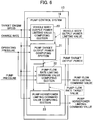
- Fig. 6 shows a control configuration of the pump control system according to the first embodiment of the present invention.
- the controller 13 includes the pump control system 19 as part of functions.
- the pump control system 19 includes a vehicle body output power limiting value computing section 20 that also serves as an electric-storage-device-12a state value monitoring section, a pump target output power computing section 21, a pump flow rate limiting command value computing section 22, and a pump horsepower limiting command value computing section 23.
- the vehicle body output power limiting value computing section 20 receives a target engine speed determined by the EC dial 14 or the like and the charge rate of the electric storage device 12a that is the signal from the BCU 12b, and computes a vehicle body output power limiting value by the engine 6 and the generator motor 8b.
- the pump target output power computing section 21 receives the plurality of operating pressures that are the signals from the plurality of operating pressure sensors 15b and the target engine speed, inputs therein the vehicle body output power limiting value computed by the vehicle body output power limiting value computing section 20, and computes present pump target output power.
- the pump flow rate limiting command value computing section 22 receives the plurality of operating pressures, the delivery pressure (pump pressure) of the hydraulic pump 9 that is the signal from the pump pressure sensor 9a, and the target engine speed, inputs therein the pump target output power computed by the pump target output power computing section 21, and computes the pump flow rate target value and the pump flow rate limiting command value.
- the pump horsepower limiting command value computing section 23 receives the target engine speed, inputs therein the target engine speed, the pump target output power computed by the pump target output power computing section 21, and the pump flow rate target value computed by the pump flow rate limiting command value computing section 22, and computes the pump horsepower limiting command value.
- the vehicle body output power limiting value computing section 20 computes, as the vehicle body output power limiting value, pump maximum output power in a present state of charge of the electric storage device 12a. Moreover, the vehicle body output power limiting value computing section 20 computes the vehicle body output power limiting value allowable by a vehicle body on the basis of maximum output power of the engine 6 at a present engine speed and maximum output power of the generator motor 8b in the present state of charge of the electric storage device 12a.
- the pump target output power computing section 21 computes present pump demanded power of the hydraulic pump 9 on the basis of work related information. In addition, the pump target output power computing section 21 limits the present pump demanded power in response to a degree of reduction of the state of charge of the electric storage device 12a when the state of charge of the electric storage device 12a acquired from the battery control unit (BCU) (electric storage control system) 12b is lower than a preset threshold (40%), and computes this limited present pump demanded power as the present pump target power. Moreover, the pump target output power computing section 21 computes a pump output power limiting value that is pump output power corresponding to the present state of charge of the electric storage device 12a on the basis of the vehicle body output power limiting value computed by the vehicle body output power limiting value computing section 20. In addition, the pump target output power computing section 21 performs computation to limit the present pump demanded power in response to the degree of reduction of the state of charge of the electric storage device 12a on the basis of this pump output power limiting value.
- the pump flow rate limiting command value computing section 22 computes the pump flow rate limiting command value in such a manner that output power of the hydraulic pump 9 does not exceed the pump target output power on the basis of the present pump target output power. In addition, the pump flow rate limiting command value computing section 22 computes the pump flow rate target value on the basis of the plurality of operation signals and the pump target output power, and computes the pump flow rate limiting command value by converting this pump flow rate target value into a target displacement of the hydraulic pump 9.
- the pump horsepower limiting command value computing section 23 computes the pump horsepower limiting command value for exercising control over the pump horsepower control valve 52 such that the delivery flow rate of the hydraulic pump 9 limited by the pump horsepower control valve 52 matches the pump flow rate target value computed by the pump flow rate limiting command value computing section 22.
- Fig. 7 shows contents of control by the vehicle body output power limiting value computing section 20 according to the first embodiment of the present invention.
- the vehicle body output power limiting value computing section 20 has an engine maximum torque computing section 20a, an assist powering torque computing section 20b, an assist ratio computing section 20c, a multiplication section 20d, an addition section 20e, a horsepower computing section 20f, and an output power limiting value computing section 20g.
- the engine maximum torque computing section 20a is a control table in which characteristics L7 of an engine maximum torque relative to the target engine speed are set, and computes the engine maximum torque corresponding to the target engine speed at the time from the target engine speed.
- the characteristics L7 of the engine maximum torque relative to the target engine speed may be set in accordance with specifications of the engine 6 to be used.
- the assist powering torque computing section 20b is a control table in which characteristics L8 of a maximum powering torque of the generator motor 8b relative to the target engine speed are set, and calculates a maximum powering torque of the generator motor 8b corresponding to the target engine speed at the time from the target engine speed.
- the characteristics L8 of the maximum powering torque of the generator motor 8b relative to the target engine speed may be set in accordance with specifications of the generator motor 8b to be used.
- a sum of the engine maximum torque and the maximum powering torque is multiplied by the engine speed, and allowable output power (vehicle body output power allowable value) by the vehicle body at the present engine speed is computed by the engine maximum torque computing section 20a, the assist powering torque computing section 20b, the addition section 20e, the horsepower computing section 20f, and the output power limiting value computing section 20g.
- the assist ratio computing section 20c is a control table in which characteristics L9 of an assist ratio relative to the charge rate of the electric storage device 12a are set, and calculates an assist ratio corresponding to the charge rate at the time from the charge rate.
- the multiplication section 20d multiplies the maximum powering torque computed by the assist powering torque computing section 20b by the assist ratio to calculate the maximum powering torque used for computing the vehicle body output power limiting value.
- the characteristics L9 of the assist ratio relative to the charge rate are such that the assist ratio is 1 when the charge rate is high and the assist ratio is 0 when the charge rate is low.
- the maximum powering torque used for computing the vehicle body output power limiting value is changed in response to the charge rate by multiplying the maximum powering torque computed by the assist powering torque computing section 20b by the assist ratio.
- the assist powering torque computing section 20b computes the vehicle body output power limiting value using the charge rate that is a state value of the electric storage device 12a.
- Fig. 8 shows an example of the characteristics L9 of the assist ratio relative to the charge rate in the assist ratio computing section 20c.
- the assist ratio is set to 1 at the charge rate of 40%, whereby the vehicle body output power limiting value corresponds to maximum power of the vehicle body.
- the assist ratio is set to 0 at the charge rate of 30%, whereby the vehicle body output power limiting value corresponds to output power of only the engine 6.
- the assist ratio linearly decreases from 1 to 0 between 40% and 30% of the charge rate.
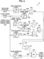
- Fig. 9 shows contents of control by the pump target output power computing section 21 according to the first embodiment of the present invention.
- the pump target output power computing section 21 has a pump demanded power computing section 21a, an engine speed gain computing section 21b, a pump output power limiting value computing section 21c, a pump minimum power setting section 21d, a pump maximum power setting section 21e, a pump reference power computing section 21f, a multiplication section 21g, a subtraction section 21h, a subtraction section 21i, a division section 21j, a multiplication section 21k, and a minimum value selection section 21m.
- the pump demanded power computing section 21a is a control table in which characteristics L10 of a plurality of pump demanded power in response to the respective plurality of operating pressures (operation signals) are set, and calculates present pump demanded power S20 corresponding to the operating pressure (operation signal) at the time from the operating pressure (operation signal).
- the characteristics L10 of the plurality of pump demanded power have optimum maximum demanded power (to be described later) in response to a type of driving or work (for example, excavation or swing/boom raising) of each actuator corresponding to the operating pressure, and are set such that only the pump power necessary to drive the actuator is output. Therefore, it is possible to exercise pump control non-wastefully with good fuel economy.
- the characteristics L10 of the pump demanded power are set while it is assumed that the engine speed is maximum engine speed.
- the engine speed gain computing section 21b is a control table in which characteristics L11 of a gain having a maximum of 1 in response to the target engine speed are set, and calculates an engine speed gain corresponding to the target engine speed at the time from the target engine speed.
- the characteristics L10 are set while it is assumed that the engine speed is the maximum engine speed. Owing to this, when the engine speed is low, the gain is set lower than 1 and the output power is adjusted by the gain in such a manner that output power is responsive to the engine speed.
- the multiplication section 21g multiplies the pump demanded power S2 computed by the pump demanded power computing section 21a by the engine speed gain computed by the engine speed gain computing section 21b to calculate pump demanded power S3 as the pump target output power (hereinafter referred to as pump target output power S3).
- the pump output power limiting value computing section 21c is a control table in which characteristics L12 for converting the vehicle body output power limiting value computed by the vehicle body output power limiting value computing section 20 into a value corresponding to pump output power, and calculates a pump output power limiting value S21 corresponding to the vehicle body output power limiting value at the time from the vehicle body output power limiting value.
- the pump output power limiting value S21 is the pump maximum output power in the present state of charge of the electric storage device 12a (maximum output power supplied to or allowed for the vehicle body by the electric storage device 12a).
- the vehicle body output power limiting value is a value that includes demanded power of all driven sections including the hydraulic pump 9 and auxiliary machines.
- the pump minimum power setting section 21d is a control table in which characteristics L13 of pump minimum power in response to the target engine speed are set, and calculates pump minimum power S8 corresponding to the target engine speed at the time from the target engine speed.
- the pump minimum power denotes stationary output power of the hydraulic pump 9 that can be driven solely by the engine 6 without the need of assist from the generator motor 8b.
- the characteristics L13 a value into which the vehicle body output power limiting value at the assist ratio of 0 (minimum) is converted using the characteristics L12 may be basically set.
- the pump maximum power setting section 21e is a control table in which characteristics L14 of pump maximum power in response to the target engine speed are set, and calculates pump maximum power S22 corresponding to the target engine speed at the time from the target engine speed.
- the pump maximum power is a pump output power limiting maximum value corresponding to a normal state in which the state of charge of the electric storage device 12a is equal to or higher than the threshold (40%).
- the pump maximum power is pump maximum output power as that of the vehicle body obtained by a sum of the maximum output power of the engine 6 and assist maximum output power of the generator motor 8b.
- the characteristics L14 a value into which the vehicle body output power limiting value at the assist ratio of 1 (maximum) is converted using the characteristics L12 may be basically set.
- the subtraction section 21h subtracts the pump minimum power S8 computed by the pump minimum power setting section 21d from the pump output power limiting value S21 computed by the pump output power limiting value computing section 21c, and outputs a resultant difference as allowable assist power S1 for the hydraulic pump 9.
- the subtraction section 21i subtracts the pump minimum power S8 computed by the pump minimum power setting section 21d from the pump maximum power S22 computed by the pump maximum power setting section 21e, and outputs a resultant difference as maximum assist power S2 for the hydraulic pump 9.
- the division section 21j divides the allowable assist power S1 by the maximum assist power S2 to compute a proportion S4 of the allowable assist power S1 in the maximum assist power S2.
- This proportion S4 is used as a limiting ratio for limiting the pump target output power S3 that is the present pump demanded power in the multiplication section 21k.
- This limiting ratio S4 is a value that denotes the degree of reduction of the state of charge of the electric storage device 12a when the state of charge of the electric storage device 12a is lower than 40% that is the preset threshold.
- the multiplication section 21k calculates pump target output power S5 by multiplying the pump target output power S3 calculated by the multiplication section 21g by the limiting ratio S4.
- the assist ratio computed by the assist ratio computing section 20c is 1. Therefore, the vehicle body output power limiting value becomes a maximum, and the pump output power limiting value S21 computed by the pump output power limiting value computing section 21c is equal to the pump maximum power S22 computed by the pump maximum power setting section 21e.
- the allowable assist power S1 is equal in value to the maximum assist power S2 and the limiting ratio S4 becomes 1; thus, it is possible to output the pump demanded power S3 computed by the multiplication section 21g without limitation.
- the assist ratio computed by the assist ratio computing section 20c becomes 0.5.
- the vehicle body output power limiting value is thus a value to which 50% of assist output power is added.
- the allowable assist power S1 is 50% of the maximum assist power S2 and the limiting ratio S4 becomes 0.5; thus, the pump demanded power S3 computed by the multiplication section 21g is limited to 50%.
- the pump reference power computing section 21f is a control table in which characteristics L15 of reference power of the hydraulic pump 9 in response to the target engine speed are set, and calculates pump reference power S24 corresponding to the target engine speed at the time from the target engine speed.
- the pump reference power computing section 21f sets an upper limit of the output power of the hydraulic pump 9 irrespective of the demanded power by the operating pressure in such a manner that the pump output power is not excessive with respect to the engine output power.
- the minimum value selection section 21m selects lower power out of the pump target output power S5 calculated by the multiplication section 21k and the pump reference power S24 calculated by the pump reference power computing section 21f, and determines the selected power as final pump target output power.
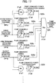
- Fig. 17 specifically shows part of the pump demanded power computing section 21a shown in Fig. 9 .
- the pump demanded power computing section 21a has a boom raising demanded power computing section 21a1, a swing demanded power computing section 21a2, an arm crowding demanded power computing section 21a3, a bucket crowding demanded power computing section 21a4, a minimum value selection section 21a5, a swing/boom raising demanded power computing section 21a6, a minimum value selection section 21a7, an excavation demanded power computing section 21a8, and a maximum value selection section 21a9.
- the boom raising demanded power computing section 21a1 is a control table in which characteristics L10a of pump demanded power in response to the operating pressure for boom raising are set, and calculates pump demanded power S20a corresponding to the operating pressure (operation signal) at the time from the operating pressure (operation signal).
- the characteristics L10a of the pump demanded power are set such that the pump demanded power becomes maximum demanded power in a region in which the operating pressure is equal to or higher than a constant operating pressure.
- the maximum demanded power for the boom raising is, for example, 75 kW.
- the swing demanded power computing section 21a2 is a control table in which characteristics LlOb of pump demanded power in response to the operating pressure for swing are set, and calculates pump demanded power S20b corresponding to the operating pressure (operation signal) at the time from the operating pressure (operation signal).
- the characteristics L10b of the pump demanded power are set such that the pump demanded power becomes the maximum demanded power in a region in which the operating pressure is equal to or higher than a constant operating pressure.
- the maximum demanded power for the swing is, for example, 60 kW.
- the arm crowding demanded power computing section 21a3 is a control table in which characteristics L10c of pump demanded power in response to the operating pressure for arm crowding are set, and calculates pump demanded power S20c corresponding to the operating pressure (operation signal) at the time from the operating pressure (operation signal).
- the characteristics L10c of the pump demanded power are set such that the pump demanded power becomes maximum demanded power in a region in which the operating pressure is equal to or higher than a constant operating pressure.
- the maximum demanded power for the arm crowding is, for example, 60 kW.
- the bucket crowding demanded power computing section 21a4 is a control table in which characteristics L10d of pump demanded power in response to the operating pressure for bucket crowding are set, and calculates pump demanded power S20d corresponding to the operating pressure (operation signal) at the time from the operating pressure (operation signal).
- the characteristics L10d of the pump demanded power are set such that the pump demanded power becomes maximum demanded power in a region in which the operating pressure is equal to or higher than a constant operating pressure.
- the maximum demanded power for the bucket crowding is, for example, 40 kW.
- the characteristics L10a, L10b, L10c, and LlOd of the pump demanded power have optimum maximum demanded power for driving the corresponding actuators, and are set such that only the pump demanded power necessary to drive the boom cylinder 3d in a boom raising direction, drive the swing hydraulic motor 3g, drive the arm cylinder 3e in an arm crowding direction, or drive the bucket cylinder 3f in a bucket crowding direction is output. Therefore, it is possible to exercise pump control non-wastefully with good fuel economy.
- These characteristics L10a, L10b, L10c, and L10d of the pump demanded power are set while it is assumed that the engine speed is the maximum engine speed.
- the minimum value selection section 21a5 selects a lower operating pressure out of the operating pressure for the boom raising and the operating pressure for the swing, and outputs the selected operating pressure as the operating pressure for swing/boom raising.
- the swing/boom raising demanded power computing section 21a6 is a control table in which characteristics LlOe of pump demanded power in response to the operating pressure for swing/boom raising are set, and calculates pump demanded power S20e corresponding to the operating pressure (operation signal) for the swing/boom raising selected by the minimum value selection section 21a5 at the time from the operating pressure (operation signal).
- the characteristics LlOe of the pump demanded power are set such that the pump demanded power becomes maximum demanded power in a region in which the operating pressure is equal to or higher than a constant operating pressure.
- the maximum demanded power for the swing/boom raising is, for example, 90 kW higher than maximum demanded power for excavation described below.
- the characteristics L10e of the pump demanded power have optimum maximum demanded power for the swing/boom raising, and are set such that only the pump power necessary for the swing/boom raising is output. Therefore, it is possible to exercise pump control non-wastefully with good fuel economy.
- the characteristics L10e of the pump demanded power are set while it is assumed that the engine speed is the maximum engine speed.
- the minimum value selection section 21a7 selects a lower operating pressure out of the operating pressure for the arm crowding and the operating pressure for the bucket crowding, and outputs the selected operating pressure as the operating pressure for excavation.
- the excavation demanded power computing section 21a8 is a control table in which characteristics L10f of pump demanded power in response to the operating pressure for excavation are set, and calculates pump demanded power S20f corresponding to the operating pressure (operation signal) for the excavation selected by the minimum value selection section 21a7 at the time from the operating pressure (operation signal).
- the characteristics LlOf of the pump demanded power are set such that the pump demanded power becomes maximum demanded power in a region in which the operating pressure is equal to or higher than a constant operating pressure.
- the maximum demanded power for the excavation is, for example, 70 kW.
- the characteristics LlOf of the plurality of pump demanded power have optimum maximum demanded power for the excavation, and are set such that only the pump power necessary for the excavation is output. Therefore, it is possible to exercise pump control non-wastefully with good fuel economy.
- the characteristics LlOf of the pump demanded power are set while it is assumed that the engine speed is maximum engine speed.
- the maximum value selection section 21a9 selects the maximum pump demanded power among the pump demanded power S20a to S20f computed by the boom raising demanded power computing section 21a1, the swing demanded power computing section 21a2, the arm crowding demanded power computing section 21a3, the bucket crowding demanded power computing section 21a4, the swing/boom raising demanded power computing section 21a6, and the excavation demanded power computing section 21a8, and outputs the selected power as the pump demanded power S20.
- pump demanded power is calculated for operations including travelling, boom lowering, arm dumping, bucket dumping, and preparation (attachment) other than the boom lowering, the swing, the arm crowding, the bucket crowding, the swing/boom raising, and the excavation shown herein.
- the maximum value selection section 21a9 selects a maximum value for each operation.
- only the swing/boom raising and the excavation are explained as types of compound operations in the present embodiment; however, operations for individually setting the pump demanded power other than these operations may be set as needed.
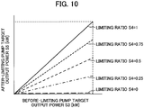
- Fig. 10 shows limiting on pump target output power by the limiting ratio S4 of the pump output power based on the vehicle body output power limiting value while a horizontal axis represents the before-limiting pump target output power S3 and a vertical axis represents the after-limiting pump target output power S5.
- the pump target output power is not limited; thus, the before-limiting pump target output power S3 is equal to the after-limiting pump target output power S5. As the limiting ratio S4 is lower, the after-limiting pump target output power S5 becomes lower. When the limiting ratio S4 is 0, the pump target output power S5 becomes 0.
- Fig. 11 shows contents of control by the pump flow rate limiting command value computing section 22 according to the first embodiment of the present invention.
- the pump flow rate limiting command value computing section 22 has a demanded flow rate computing section 22a, an engine speed gain computing section 22b, a multiplication section 22c, a target flow rate computing section 22d, a minimum value selection section 22e, a target displacement computing section 22f, and a flow rate limiting value computing section 22g.
- the demanded flow rate computing section 22a is a control table in which characteristics L16 of a plurality of pump demanded flow rates in response to the plurality of operating pressures (operation signals) are set, and calculates a present pump demanded flow rate corresponding to the operating pressure (operation signal) at the time from the operating pressure (operation signal).
- the characteristics L16 of the pump demanded flow rate are set such that only the necessary pump flow rate is output to correspond to the operation signal. Therefore, it is possible to exercise pump control non-wastefully with good fuel economy.
- the characteristics L16 of the pump demanded flow rate are set while it is assumed that the engine speed is the maximum engine speed.
- the engine speed gain computing section 22b is a control table in which characteristics L11 of the gain having the maximum of 1 in response to the target engine speed are set, and calculates an engine speed gain corresponding to the target engine speed at the time from the target engine speed, similarly to the engine speed gain computing section 21b shown in Fig. 9 .
- the engine speed gain computing section 22b computes an engine speed gain in response to the target engine speed at the time using the characteristics L11 of the gain.
- the multiplication section 22c multiplies this engine speed gain by the pump demanded flow rate calculated by the demanded flow rate computing section 22a, thereby adjusting the pump demanded flow rate to a flow rate in response to the target engine speed.
- the target flow rate computing section 22d computes the pump flow rate that enables the present pump target output power using the pump target output power that is a computation result of the pump target output power computing section 21 and the delivery pressure (pump pressure) of the hydraulic pump 9 that is the signal from the pump pressure sensor 9a.
- the actuator pressure that is the signal from one of the actuator pressure sensors 9b may be used as an alternative to the pump pressure. In this case, since the plurality of actuator pressure sensors 9b are present, the highest pressure among the actuator pressures may be selected and used.
- the minimum value selection section 22e selects a lower flow rate out of the demanded flow rate based on the operating pressure and the pump flow rate that enables the pump target output power, and determines the pump flow rate target value.
- the pump flow rate is controlled such that the pump flow rate is suppressed to be equal to or lower than the flow rate that enables the pump target output power while the necessary pump flow rate is delivered in response to the operating pressure, and that the output power of the hydraulic pump 9 does not exceed the pump target output power. It is thereby possible to control the fuel consumption and the remaining charge amount.
- the pump flow rate target value computed here corresponds to the pump flow rate target value shown in Fig. 5 .
- the target displacement computing section 22f computes a pump target displacement by dividing the pump flow rate target value determined by the minimum value selection section 22e by the target engine speed.
- the flow rate limiting value computing section 22g is a control table in which characteristics L17 of a pump flow rate limiting command value in response to the pump target displacement are set, and calculates a pump flow rate limiting command value corresponding to the pump target displacement at the time from the pump target displacement.
- the characteristics L17 are set in accordance with specifications of the hydraulic pump 9.
- the controller 13 controls the pump flow rate by controlling the pump flow rate limiting solenoid valve 18b of the regulator 18 in such a manner that the pump flow rate limiting command value is obtained.
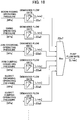
- Fig. 18 specifically shows part of the demanded flow rate computing section 22a shown in Fig. 11 .
- the demanded flow rate computing section 22a has a boom raising demanded flow rate computing section 22a1, a swing demanded flow rate computing section 22a2, an arm crowding demanded flow rate computing section 22a3, an arm dumping demanded flow rate computing section 22a4, a bucket crowding demanded flow rate computing section 22a5, a bucket dumping demanded flow rate computing section 22a6, and a maximum value selection section 22a7.
- a left-and-right-travel-motors demanded flow rate computing section, a boom lowering demanded flow rate computing section, and a preparation (attachment) demanded flow rate computing section are not shown.
- the boom raising demanded flow rate computing section 22a1 is a control table in which characteristics L16a of a pump demanded flow rate in response to the operating pressure for boom raising are set, and calculates a pump demanded flow rate corresponding to the operating pressure (operation signal) at the time from the operating pressure (operation signal).
- the characteristics L16a of the pump demanded flow rate are set such that the pump demanded flow rate becomes a maximum pump flow rate in a region in which the operating pressure is equal to or higher than a constant operating pressure.
- the swing demanded flow rate computing section 22a2 is a control table in which characteristics L16b of a pump demanded flow rate in response to the operating pressure for swing are set, and calculates a pump demanded flow rate corresponding to the operating pressure (operation signal) at the time from the operating pressure (operation signal).
- the characteristics L16b of the pump demanded flow rate are set such that the pump demanded flow rate becomes a maximum pump flow rate in a region in which the operating pressure is equal to or higher than a constant operating pressure.
- the arm crowding demanded flow rate computing section 22a3 is a control table in which characteristics L16c of a pump demanded flow rate in response to the operating pressure for arm crowding are set, and calculates a pump demanded flow rate corresponding to the operating pressure (operation signal) at the time from the operating pressure (operation signal).
- the characteristics L16c of the pump demanded flow rate are set such that the pump demanded flow rate becomes a maximum pump flow rate in a region in which the operating pressure is equal to or higher than a constant operating pressure.
- the arm dumping demanded flow rate computing section 22a4 is a control table in which characteristics L16d of a pump demanded flow rate in response to the operating pressure for arm dumping are set, and calculates a pump demanded flow rate corresponding to the operating pressure (operation signal) at the time from the operating pressure (operation signal).
- the characteristics L16d of the pump demanded flow rate are set such that the pump demanded flow rate becomes a maximum pump flow rate in a region in which the operating pressure is equal to or higher than a constant operating pressure.
- the bucket crowding demanded flow rate computing section 22a5 is a control table in which characteristics L16e of a pump demanded flow rate in response to the operating pressure for bucket crowding are set, and calculates a pump demanded flow rate corresponding to the operating pressure (operation signal) at the time from the operating pressure (operation signal).
- the characteristics L16e of the pump demanded flow rate are set such that the pump demanded flow rate becomes a maximum pump flow rate in a region in which the operating pressure is equal to or higher than a constant operating pressure.
- the bucket dumping demanded flow rate computing section 22a6 is a control table in which characteristics L16f of a pump demanded flow rate in response to the operating pressure for bucket dumping are set, and calculates a pump demanded flow rate corresponding to the operating pressure (operation signal) at the time from the operating pressure (operation signal).
- the characteristics L16f of the pump demanded flow rate are set such that the pump demanded flow rate becomes a maximum pump flow rate in a region in which the operating pressure is equal to or higher than a constant operating pressure.
- the characteristics L16a to L16f of the pump demanded flow rate are set such that only the necessary pump flow rate is output to correspond to the operation signal. Therefore, it is possible to exercise pump control non-wastefully with good fuel economy. These characteristics a to L16f of the pump demanded flow rate are set while it is assumed that the engine speed is the maximum engine speed.
- the maximum value selection section 22a7 selects the maximum value of the pump demanded flow rates computed by the demanded flow rate computing sections 22a1 to 22a6 to compute the pump demanded flow rate.
- the selected pump demanded flow rate as the maximum value is given to the multiplication section 22c of Fig. 11 .
- Fig. 12 shows contents of control by the pump horsepower limiting command value computing section 23 according to the first embodiment of the present invention.
- the pump horsepower limiting command value computing section 23 has a target displacement computing section 23a, a target torque computing section 23b, a pump pressure computing section 23c, a pump pressure computing section 23d, a subtraction section 23e, a limiter 23f, and a horsepower limiting value computing section 23g.
- the target displacement computing section 23a computes the pump target displacement by dividing the pump flow rate target value calculated by the pump flow rate limiting command value computing section 22 by the target engine speed, similarly to the target displacement computing section 22f.
- the target torque computing section 23b calculates a pump target torque by dividing the pump target output power calculated by the pump target output power computing section 21 by the target engine speed.
- the pump pressure computing section 23c is a control table in which characteristics L18 of a pump pressure that is responsive to the pump target displacement calculated by the target displacement computing section 23a and that enables a maximum torque at the target displacement are set, and calculates a pump pressure S6 that enables the maximum at the pump target displacement at the time from the pump target displacement.
- the characteristics L18 are set in accordance with the specifications of the hydraulic pump 9.
- the pump pressure computing section 23d calculates a pump pressure S7 that enables the target torque at a present target displacement by dividing the pump target torque calculated by the target torque computing section 23b by the pump target displacement calculated by the target displacement computing section 23a.
- the subtraction section 23e subtracts the pump pressure S7 from the pump pressure S6 to compute a pump flow rate characteristic correction value.
- This computation result (pump flow rate characteristic correction value) often becomes a negative value. Since only the flow rate characteristic correction value having a positive value is used as the characteristics of the hydraulic pump 9, the computation result is set to have a value equal to or higher than 0 by the limiter 23f.
- the pump flow rate characteristic correction value computed here corresponds to the pump flow rate characteristic correction value of Fig. 4 .
- the horsepower limiting value computing section 23g is a control table in which characteristics L19 of a pump horsepower limiting command value in response to the pump flow rate characteristic correction value are set, and computes a pump horsepower limiting command value corresponding to the pump flow rate characteristic correction value at the time from the pump flow rate characteristic correction value.
- the characteristics L19 are similarly set in accordance with the specifications of the hydraulic pump 9.
- the controller 13 controls the pump horsepower control valve 52 by controlling the pump horsepower limiting solenoid valve 18a of the regulator 18 in such a manner that the pump horsepower limiting command value is obtained, and controls the absorption horsepower (pump horsepower) of the hydraulic pump 9.
- Fig. 13 is an explanatory diagram of effects produced by combined use of the pump flow rate limiting command value computing section 22 and the pump horsepower limiting command value computing section 23.
- the flow rate characteristics of the hydraulic pump 9 make a parallel translation by as much as the pump flow rate characteristic correction value, as shown in Fig. 4 .
- a pump operating point is denoted by, for example, Z of Fig. 13 .
- the flow rate characteristics of the hydraulic pump 9 are controlled in such a manner as to be tangent to the pump operating point Z by the pump flow rate limiting command value computing section (pump flow rate limiting command value) using the pump flow rate characteristic correction value computed by the pump horsepower limiting command value computing section 23.
- the pump horsepower control valve 52 is controlled such that the delivery flow rate of the hydraulic pump 9 limited by the pump horsepower control valve 52 matches the pump flow rate target value computed by the pump flow rate limiting command value computing section 22.
- pump horsepower limiting is designed to increase or reduce a pump flow rate with high responsiveness to a pump pressure fluctuation. Owing to this, when a pump pressure fluctuates during operation such as time of starting an actuator, pump characteristics by pump horsepower limiting are set to be matched with the operating point Z by the pump flow rate control. It is thereby possible to stabilize the pump flow rate with high responsiveness to a sudden pump pressure fluctuation, cause the pressure fluctuation to converge more quickly, and suppress hunting and unnecessary powering assist of a generator motor.
- Patent Document 1 when the remaining charge amount falls, the upper limiting value of the pump output power is limited irrespectively of the content of work. Owing to this, when output power after limitation is compared with that before limitation, the limiting (reduction) amount of the output power for the swing/boom raising is larger than that for the excavation. In other words, the ratio of the speed reduction during limitation to that during non-limitation for the swing/boom raising is higher than that for the excavation. This difference in speed reduction ratio possibly causes the operator engaged in a series of work to feel discomfort in operation and thereby feel an unnecessary stress.
- the present embodiment solves the above problem as follows.
- the operating pressure for the arm crowding and the operating pressure for the bucket crowding are generated.
- the arm crowding demanded flow rate computing section 22a3 and the bucket crowding demanded flow rate computing section 22a5 shown in Fig. 18 compute the pump demanded flow rates corresponding to the respective operating pressures.
- the maximum value selection section 22a7 selects the maximum value, this maximum pump demanded flow rate is multiplied by the engine speed gain, and the demanded flow rate based on the operating pressure is computed.
- the division section 21j shown in Fig. 9 computes the limiting ratio S4 in response to the degree of reduction of the state of charge of the electric storage device 12a.
- the multiplication section 21k multiplies the pump demanded power S3 computed by the pump demanded power computing section 21a and the multiplication section 21g by the limiting ratio S4, thereby computing the pump demanded power limited in response to the degree of reduction of the state of charge of the electric storage device 12a.
- the target flow rate computing section 22d shown in Fig. 11 computes the pump flow rate corresponding to the limited pump demanded power.
- the minimum value selection section 22e selects the lower flow rate out of the pump flow rate and the demanded flow rate based on the operating pressure and computed by the multiplication section 22c as the pump flow rate target value, and the pump flow rate limiting value is computed.
- the pump flow rate limiting value is output as the solenoid valve current command value (mA) from the controller 13 to the pump flow rate limiting solenoid valve 18b, and the pump flow rate control pressure introduced to the pump flow control valve 53 of the regulator 18 is limited to the pump flow rate limiting value.
- the pump flow rate is thereby suppressed to be equal to or lower than the flow rate that enables the pump target output power while the hydraulic pump 9 delivers the necessary pump flow rate in response to the operating pressure.
- it is thereby possible to prevent the deterioration of the electric storage device 12a due to overdischarge of the electric storage device 12a and stalling of the engine 6 due to insufficient assist or disabled assist when the charge amount of the electric storage device 12a falls.
- the boom raising demanded flow rate computing section 22a1 and the swing demanded flow rate computing section 22a2 shown in Fig. 18 compute the pump demanded flow rates corresponding to the respective operating pressures.
- the maximum value selection section 22a7 selects the maximum value out of the pump demanded flow rates, this maximum pump demanded flow rate is multiplied by the engine speed gain, and the demanded flow rate based on the operating pressure is computed.
- the target flow rate computing section 22d shown in Fig. 11 computes the pump flow rate corresponding to the pump demanded power computed by the pump target output power computing section 21.
- the minimum value selection section 22e selects the higher flow rate out of the pump flow rate and the demanded flow rate based on the operating pressure and computed by the multiplication section 22c as the pump flow rate target value, and the pump flow rate limiting value is computed.
- the pump flow rate limiting value is output as the solenoid valve current command value (mA) from the controller 13 to the pump flow rate limiting solenoid valve 18b, and the pump flow rate control pressure introduced to the pump flow control valve 53 of the regulator 18 is limited in such a manner that the pump flow rate control pressure does not exceed the pump flow rate limiting value.
- the pump flow rate is thereby suppressed to be equal to or lower than the flow rate that enables the pump target output power while the hydraulic pump 9 delivers the necessary pump flow rate in response to the operating pressure.
- it is thereby possible to prevent the deterioration of the electric storage device 12a due to overdischarge of the electric storage device 12a and stalling of the engine 6 due to insufficient assist or disabled assist when the charge amount of the electric storage device 12a falls.
- the arm crowding demanded power computing section 21a3 and the bucket crowding demanded power computing section 21a4 of Fig. 17 compute the pump demanded power S20c (maximum: 60 kW) corresponding to the operating pressure for the arm crowding and the pump demanded power S20d (maximum: 40 kW) corresponding to the operating pressure for the bucket crowding, respectively.
- the minimum value selection section 21a7 selects the higher operating pressure out of the operating pressure for the arm crowding and the operating pressure for the bucket crowding as the operating pressure for excavation.
- the excavation demanded power computing section 21a8 calculates the pump demanded power S20f (maximum: 70 kW) corresponding to the operating pressure for the excavation.
- the maximum value selection section 21a9 selects the maximum pump demanded power among the pump demanded power S20c, S20d, and S20f as the pump demanded power S20.
- the multiplication section 21g shown in Fig. 9 multiplies the pump demanded power S20 computed as described above by the engine speed gain at the time to compute the pump demanded power S3.
- the multiplication section 21k multiplies the pump demanded power S3 by the limiting ratio S4 in response to the degree of reduction of the state of charge of the electric storage device 12a, thereby computing the pump demanded power limited in response to the degree of reduction of the state of charge of the electric storage device 12a.
- This pump demanded power is transmitted to the target flow rate computing section 22d of the pump flow rate limiting command value computing section 22 shown in Fig. 11 , and the target flow rate computing section 22d computes the pump flow rate corresponding to the pump demanded power.
- the minimum value selection section 22e imposes limiting such that the demanded flow rate based on the operating pressure and computed by the multiplication section 22c does not exceed the pump flow rate corresponding to the pump demanded power, thereby computing the pump flow rate limiting value.
- the pump flow rate limiting value is output as the solenoid valve current command value (mA) from the controller 13 to the pump flow rate limiting solenoid valve 18b, and the pump flow rate control pressure introduced to the pump flow control valve 53 of the regulator 18 is limited in such a manner that the pump flow rate control pressure does not exceed the pump flow rate limiting value, and the pump flow rate is controlled.
- the boom raising demanded power computing section 21a1 and the swing demanded power computing section 21a2 of Fig. 17 compute the pump demanded power S20a (maximum: 75 kW) corresponding to the operating pressure for the boom raising and the pump demanded power S20b (maximum: 60 kW) corresponding to the operating pressure for the swing, respectively.
- the minimum value selection section 21a5 selects the higher operating pressure out of the operating pressure for the boom raising and the operating pressure for the swing as the operating pressure for the swing/boom raising.
- the swing/boom raising demanded power computing section 21a6 calculates the pump demanded power S20e (maximum: 90 kW) corresponding to the operating pressure for the swing/boom raising.
- the maximum value selection section 21a9 selects the maximum pump demanded power among the pump demanded power S20a, S20b, and S20e as the pump demanded power S20.
- the minimum value selection section 22e of the pump flow rate limiting command value computing section 22 shown in Fig. 11 imposes limiting such that the demanded flow rate based on the operating pressure and computed by the multiplication section 22c does not exceed the pump flow rate corresponding to the pump demanded power, thereby computing the pump flow rate limiting value.
- the pump flow rate limiting value is output as the solenoid valve current command value (mA) from the controller 13 to the pump flow rate limiting solenoid valve 18b, and the pump flow rate control pressure introduced to the pump flow control valve 53 of the regulator 18 is limited in such a manner that the pump flow rate control pressure does not exceed the pump flow rate limiting value and the pump flow rate is controlled.
- the present pump demanded power S3 is computed on the basis of the operating pressure that is the work related information for every operating pressure or every type of work
- the pump flow rate limiting command value is computed on the basis of the pump target output power S5 obtained by limiting the pump demanded power S3 in response to the degree of reduction of the state of charge of the electric storage device 12a
- the delivery flow rate of the hydraulic pump 9 is controlled in such a manner that the output power of the hydraulic pump 9 does not exceed the pump target output power S5.
- the output power of the hydraulic pump 9 is limited in response to the operating pressure that is the work related information. It is, therefore, possible to reduce a speed while balance is kept as a whole in a series of continuous cycle work, minimize discomfort in operation when the speed falls, suppress the operator from feeling discomfort in operation, and ensure favorable operability.
- the present pump demanded power S3 is limited in response to the degree of reduction of the state of charge of the electric storage device 12a to compute the pump target output power, and the delivery flow rate of the hydraulic pump 9 is controlled. It is thereby possible to prevent deterioration of the electric storage device 12a due to overdischarge of the electric storage device 12a and stalling of the engine 6 due to insufficient assist or disabled assist, and continuously conduct work when the charge amount of the electric storage device 12a falls.
- the present pump demanded power S3 is computed on the basis of the work related information (operating pressure that is the operation signal in the example of the drawings), the pump flow rate limiting command value is computed on the basis of the pump target output power S5 obtained by limiting the pump demanded power S3 in response to the degree of reduction of the state of charge of the electric storage device 12a, and the delivery flow rate of the hydraulic pump 9 is controlled in such a manner that the output power of the hydraulic pump 9 does not exceed the pump target output power S5.
- the output power of the hydraulic pump 9 is thereby limited in response to the work related information. It is, therefore, possible to reduce the speed while balance is kept as a whole in a series of continuous cycle work, minimize discomfort in operation when the speed falls, suppress the operator from feeling discomfort in operation, and ensure favorable operability.
- the pump horsepower limiting command value computing section 23 is provided in the controller 13.
- the pump horsepower limiting command value computing section 23 is configured to exercise control over the pump horsepower control valve 52 such that the delivery flow rate of the hydraulic pump 9 limited by the pump horsepower control valve 52 matches the pump flow rate target value computed by the pump flow rate limiting command value computing section 22. It is thereby possible to stabilize the pump flow rate with high responsiveness to a sudden pump pressure fluctuation, cause the pressure fluctuation to converge more quickly, and suppress hunting and unnecessary powering assist from the generator motor.
- a second embodiment of the present invention will next be explained.
- the second embodiment is similar to the first embodiment in main configuration. Different parts from those of the first embodiment will be explained.
- the first embodiment and the second embodiment of the present invention differ in contents of processing of the pump target output power computing section 21.
- Fig. 14 shows contents of control by the pump target output power computing section 21 according to the second embodiment of the present invention.
- the pump target output power computing section 21 has a minimum value selection section 21n, a subtraction section 21p, and an addition section 21q as well as the pump demanded power computing section 21a, the engine speed gain computing section 21b, the pump output power limiting value computing section 21c, the pump minimum power setting section 21d, the pump maximum power setting section 21e, the pump reference power computing section 21f, the multiplication section 21g, the subtraction section 21h, the subtraction section 21i, the division section 21j, the multiplication section 21k, and the minimum value selection section 21m shown in Fig. 9 .
- the minimum value selection section 21n selects a minimum value out of the before-limiting pump target output power S3 and the pump minimum power S8.
- the subtraction section 21p calculates a difference S23 between a computation result S9 of the minimum value selection section 21n and the before-limiting pump target output power S3.
- the multiplication section 21k multiplies the difference S23 by the limiting ratio S4, thereby computing a limited output power amount S10 in response to the limiting ratio S4 for the pump target output power that exceeds the pump minimum power S8.
- the addition section 21q adds the limited output power amount S10 to the computation result S9, thereby determining the after-limiting pump target output power S5 corresponding to the vehicle body output power limiting value.
- the pump target output power computing section 21 sets the pump minimum power S8 as a pump output power limiting effective threshold.
- the state of charge of the electric storage device 12a is lower than 40% that is the threshold, computation is performed in such a manner that an output power part equal to or higher than the pump output power limiting effective threshold S8 out of the pump target output power S3 is limited in response to the degree of reduction of the state of charge of the electric storage device 12a (limiting ratio S4), thereby limiting the pump target output power S3 and determining the pump target output power S5.
- Fig. 15 shows limiting on pump target output power by the pump output power limiting ratio S4 based on the vehicle body output power limiting value while the horizontal axis represents the before-limiting pump target output power S3 and the vertical axis represents the after-limiting pump target output power S5.
- the minimum value selection result S9 is equal to the before-limiting pump target output power S3. Therefore, a difference between S9 and S3 is 0, and the after-limiting pump target output power S5 is equal to the before-limiting pump target output power S3 without limiting the pump target output power irrespective of the limiting ratio S4.
- the pump target output power is not limited; thus, the before-limiting pump target output power is equal to the after-limiting pump target output power. As the limiting ratio S4 is lower, the after-limiting pump target output power becomes lower. When the limiting ratio S4 is 0, the pump target output power is equal to the pump minimum power S18 set in L13.
- the pump minimum power S8 is set to the value corresponding to the output power that can be driven solely by the engine with the powering assist from the generator motor regarded as 0. Therefore, when the pump target output power is limited to the minimum power, it is possible to cause the vehicle body to operate without reducing the charge rate of the electric storage device 12a and minimize deterioration of operator's operability.
- the other parts are similar in configuration as those according to the first embodiment.
- the second embodiment of the present invention configured as described above can attain similar effects to those of the first embodiment.
- the output power corresponding to the output power that can be driven solely by the engine and that requires the powering assist from the generator motor 8b is limited in response to the charge rate out of the pump target output power. Therefore, the output power is not limited in a low output power region in which speed reduction is not desired or speed reduction is unnecessary, so that it is possible to further suppress the deterioration of the operator's operability.
- the pump target output power computing section 21 computes the pump output power limiting maximum value that is the pump maximum power corresponding to the normal state in which the state of charge of the electric storage device 12a is equal to or higher than the threshold (40%), and the pump output power limiting value that is the pump output power corresponding to the present state of charge of the electric storage device 12a. In addition, the pump target output power computing section 21 computes the present pump demanded power as the value irrespective of the state of charge of the electric storage device 12a.
- the pump target output power computing section 21 computes the ratio of the difference between the pump output power limiting value S21 and the pump output power limiting effective threshold (pump minimum power S8) to the difference between the pump output power limiting maximum value (pump maximum power S22) and the pump output power limiting effective threshold (pump minimum power S8) as the limiting ratio S4 that denotes the degree of reduction of the state of charge of the electric storage device 12a, and computes the pump target output power by multiplying the difference between the present pump demanded power and the pump output power limiting effective threshold (pump minimum power S8) by the limiting ratio S4.
- a limiting amount on the present pump target output power can be determined by simple calculation that does not require complicated computation.
- the pump target output power computing section 21 computes the stationary output power of the hydraulic pump 9 that can be driven solely by the engine without the need of assist from the generator motor 8b as the pump output power limiting effective threshold, computes the pump maximum output power as the vehicle body obtained by the sum of the maximum output power of the engine 6 and the assist maximum output power of the generator motor 8b as the pump output power maximum value, and computes the pump maximum output power in the present state of charge of the electric storage device 12a as the pump output power limiting value.
- the output power limiting is not imposed on the pump target output power equal to or lower than the stationary output power of the hydraulic pump 9 that can be driven solely by the engine. Therefore, it is possible to minimize the output power limiting and minimize the deterioration of operator's operability.
Landscapes
- Engineering & Computer Science (AREA)
- Combustion & Propulsion (AREA)
- Chemical & Material Sciences (AREA)
- Mechanical Engineering (AREA)
- General Engineering & Computer Science (AREA)
- Transportation (AREA)
- Structural Engineering (AREA)
- Civil Engineering (AREA)
- Mining & Mineral Resources (AREA)
- Automation & Control Theory (AREA)
- Physics & Mathematics (AREA)
- Fluid Mechanics (AREA)
- Power Engineering (AREA)
- Operation Control Of Excavators (AREA)
- Hybrid Electric Vehicles (AREA)
- Control Of Vehicle Engines Or Engines For Specific Uses (AREA)
Abstract
Description
- The present invention relates to a hybrid construction machine such as a hydraulic excavator equipped with an electric storage device and a generator motor.
- There is known, as a type of a construction machine such as a hydraulic excavator, a hybrid construction machine configured such that an engine is miniaturized to reduce fuel consumption, a generator motor (an assist motor) is connected to the engine to make up a transitional or steady shortfall in output power, and an electric storage device is charged using the output power of the engine, while powering assist is given to drive a hydraulic pump using electric power of the electric storage device.
Patent Document 1 describes one example of the hybrid construction machine. -
Patent Document 1 proposes exercising control such that a powering assist amount is limited and pump absorption horsepower is limited to prevent the electric storage device from turning into an overdischarge state when an operating state is in a work mode and a remaining charge amount of the electric storage device falls. In other words, a total value of powering output power of a generator motor determined from preset discharge electric energy for a degree of reduction of a charge amount of the electric storage device and output power of an engine is set as an upper limiting value of the pump absorption horsepower, and output power control is exercised such that maximum output power (or torque) from a hydraulic pump is limited to prevent the maximum output power (or torque) from exceeding the value. - Patent Document 1: Japanese Patent No.
3941951 - Generally, no problem occurs to the hybrid construction machine when the remaining charge amount of the electric storage device is sufficient. However, a problem such as deterioration of the electric storage device due to excessive reduction of the remaining charge amount (overdischarge) and engine stalling due to insufficient assist or disabled assist occurs to the hybrid construction machine.
- According to
Patent Document 1, when the remaining charge amount of the electric storage device falls, output power control is exercised such that the powering assist amount is limited and the maximum output power torque of the hydraulic pump is limited as described above. Therefore, it is possible to prevent the deterioration of the electric storage device due to the overdischarge of the electric storage device and the engine stalling due to the disabled assist, and to continue vehicle body operation. However,Patent Document 1 has the following problem. Simply limiting the maximum output power of the hydraulic pump irrespective of a content of work makes it impossible to prevent the overdischarge of the electric storage device while maintaining operability in a series of continuous cycle work. - For example, when the hydraulic excavator loads gravel and soil into a dump truck, an operating cycle of excavation, swing/boom raising, discharge of gravel and sand, return to swing, excavation, ... is repeated. When attention is paid to the excavation and the swing/boom raising, these operations are heavy load operations that require assist from the generator motor with electric power supplied from the electric storage device. Furthermore, the swing/boom raising is normally higher than the excavation in demanded pump output power.
- In
Patent Document 1, when the remaining charge amount falls, the upper limiting value of the pump output power is limited irrespectively of the content of work. Owing to this, when output power after limitation is compared with that before limitation, a limiting (reduction) amount of the output power for the swing/boom raising is larger than that for the excavation. In other words, a ratio of a speed reduction during limitation to that during non-limitation for the swing/boom raising is higher than that for the excavation. This difference in speed reduction ratio possibly causes an operator engaged in a series of work to feel discomfort in operation and thereby feel an unnecessary stress. - Moreover, types of work with the hydraulic excavator cannot be completely classified into the excavation, the swing/boom raising, and the like. Furthermore, necessary output power is variable even for each of the excavation and the swing/boom raising, so that simply limiting the upper limit of the output power of the hydraulic pump makes it difficult to prevent the overdischarge of the electric storage device while maintaining the operability.
- An object of the present invention is to provide a hybrid construction machine that can prevent deterioration of an electric storage device due to overdischarge of the electric storage device and engine stalling due to insufficient assist or disabled assist to ensure continuous work when a charge amount of the electric storage device falls, while suppressing an operator from feeling discomfort in operation and ensuring favorable operability.
- To solve the problem, the present invention provides a hybrid construction machine, comprising: an engine; at least one generator motor; an electric storage device that is charged when the generator motor is caused to perform a power generation operation and that is discharged when the generator motor is caused to perform a powering operation; an electric storage control system that computes a state of charge of the electric storage device and monitors the electric storage device; a variable displacement hydraulic pump driven by torques of the engine and the generator motor; a plurality of hydraulic actuators driven by a hydraulic fluid delivered from the hydraulic pump; a plurality of operation devices that output operation signals in response to operation amounts for the plurality of hydraulic actuators and instruct the hydraulic actuators to operate; a controller that controls charge electric power and discharge electric power of the generator motor and a delivery flow rate and output power of the hydraulic pump; and a regulator that controls a displacement of the hydraulic pump to control the delivery flow rate of the hydraulic pump, wherein the controller includes a pump target output power computing section that computes present pump target output power of the hydraulic pump, and a pump flow rate limiting command value computing section that computes a pump flow rate limiting command value for controlling the delivery flow rate and the output power of the hydraulic pump, wherein the pump target output power computing section is configured to compute present pump demanded power of the hydraulic pump on the basis of work related information, limit the present pump demanded power in response to a degree of reduction of a state of charge of the electric storage device acquired from the electric storage control system when the state of charge of the electric storage device is lower than a preset threshold, and compute the limited present pump demanded power as the present pump target output power, and the pump flow rate limiting command value computing section is configured to compute the pump flow rate limiting command value on the basis of the present pump target output power in such a manner that the output power of the hydraulic pump does not exceed the pump target output power, and wherein the regulator controls the displacement of the hydraulic pump and controls the delivery flow rate of the hydraulic pump on the basis of the pump flow rate limiting command value.
- In this way, when the state of charge of the electric storage device is lower than the threshold, then the present pump demanded power is limited in response to the degree of reduction of the state of charge of the electric storage device to compute the pump target output power, and the delivery flow rate of the hydraulic pump is controlled. It is therefore possible to prevent deterioration of the electric storage device due to overdischarge of the electric storage device and engine stalling due to insufficient assist or disabled assist thereby to continuously conduct work when the charge amount of the electric storage device falls.
- Furthermore, the present pump demanded power is computed on the basis of work related information, the pump flow rate limiting command value is computed on the basis of the pump target output power that is the pump demanded power limited in response to the degree of reduction of the state of charge of the electric storage device in such a manner that the output power of the hydraulic pump does not exceed the pump target output power, and the delivery flow rate of the hydraulic pump is controlled. It is therefore possible to limit the output power of the hydraulic pump in response to the work related information and to reduce a speed while balance is kept as a whole in a series of continuous cycle work and minimize discomfort in operation when the speed falls, thereby to suppress an operator from feeling discomfort in operation and ensure favorable operability.
- According to the present invention, it is possible to prevent deterioration of an electric storage device due to overdischarge of the electric storage device and engine stalling due to insufficient assist or disabled assist when a charge amount of the electric storage device falls, ensure that work is continuously conducted, suppress an operator from feeling discomfort in operation, and ensure favorable operability.
-
-
Fig. 1 shows an external view of a hybrid hydraulic excavator as one example of a construction machine according to a first embodiment of the present invention. -
Fig. 2 shows a configuration of a hybrid system in the hybrid hydraulic excavator. -
Fig. 3 shows an outline of a hydraulic system in the hybrid hydraulic excavator. -
Fig. 4 is an operation explanatory diagram for pump horsepower limiting by a pumphorsepower control valve 52. -
Fig. 5 is an operation explanatory diagram for pump flow rate control by a pump flow control valve. -
Fig. 6 shows a control configuration of a pump control system according to the first embodiment of the present invention. -
Fig. 7 shows contents of control by a vehicle body output power limiting value computing section according to the first embodiment of the present invention. -
Fig. 8 shows an example of characteristics of an assist ratio relative to a charge rate in an assist ratio computing section. -
Fig. 9 shows contents of control by a pump target output power computing section according to the first embodiment of the present invention. -
Fig. 10 shows limiting on pump target output power by a pump output power limiting ratio S4 based on a vehicle body output power allowable value while a horizontal axis represents before-limiting first pump target output power S3 and a vertical axis represents after-limiting second pump target output power S5. -
Fig. 11 shows contents of control by a pump flow rate limiting command value computing section according to the first embodiment of the present invention. -
Fig. 12 shows contents of control by a pump horsepower limiting command value computing section according to the first embodiment of the present invention. -
Fig. 13 is an explanatory diagram of effects produced by combined use of the pump flow rate limiting command value computing section and the pump horsepower limiting command value computing section. -
Fig. 14 shows contents of control by the pump target output power computing section according to a second embodiment of the present invention. -
Fig. 15 shows limiting on pump target output power by the pump output power limiting ratio S4 based on the vehicle body output power allowable value while the horizontal axis represents the before-limiting pump target output power S3 and the vertical axis represents after-limiting pump target output power S5. -
Fig. 16 shows details of a regulator. -
Fig. 17 shows details of a pump demanded power computing section shown inFig. 9 . -
Fig. 18 shows details of a demanded flow rate computing section shown inFig. 11 . - Embodiments of the present invention will be described hereinafter with reference to the drawings.
-
Fig. 1 shows an external view of a hybrid hydraulic excavator as one example of a construction machine according to the present embodiment. - In
Fig. 1 , the hybrid hydraulic excavator (construction machine) is generally configured with a crawler typelower travel structure 100, anupper swing structure 200 swingably provided on thelower travel structure 100, and a front work implement 300 equipped with excavation means and the like. - A pair of left and right travel hydraulic motors 3ha and 3hb are disposed in the
lower travel structure 100.Crawler belts 1a and 1b are driven to rotate independently of each other by the travel hydraulic motors 3ha and 3hb, speed reduction mechanisms of the travel hydraulic motors 3ha and 3hb, and the like, and travel forward or rearward. - The
upper swing structure 200 is provided with acabin 4 that forms anoperation room 4a in which a plurality of operation devices 15 (Fig. 3 ) performing various operations on the hydraulic excavator, a cab seat on which an operator is seated, and the like are disposed, prime movers such as anengine 6 and agenerator motor 8b shown inFig. 2 , anelectric storage device 12a, ahydraulic pump 9, a swinghydraulic motor 3g, a swing electric motor lib, and the like. Theupper swing structure 200 is driven to swing in a right direction or a left direction with respect to thelower travel structure 100 by the swinghydraulic motor 3g and the swingelectric motor 11b. Various meters and gauges that enable the operator to confirm a status of the hydraulic excavator (construction machine) and a display device 5 (Fig. 3 ) that displays machine information are provided in theoperation room 4a within thecabin 4. - The
front work implement 300 is configured with aboom 3a, anarm 3b, and abucket 3c. Theboom 3a is vertically moved by aboom cylinder 3d, thearm 3b is operated to a dumping side (open side) or a crowding side (shoveling side) by anarm cylinder 3e, and thebucket 3c is operated to the dumping side or the crowding side by abucket cylinder 3f. Thebucket 3c configures excavating means. -
Fig. 2 shows a configuration of a hybrid system in the hybrid hydraulic excavator. - In
Fig. 2 , the hybrid system has theengine 6, an engine control unit (ECU) 7 that controls theengine 6, thegenerator motor 8b and thehydraulic pump 9 coupled to theengine 6, acontrol valve 10, the swingelectric motor 11b, theelectric storage device 12a, afirst inverter 8a, asecond inverter 11a, a battery control unit (BCU) 12b, and a machine controller (hereinafter may be simply referred to as controller) 13. - The
control valve 10 opens or closes a hydraulic path corresponding to each of theboom cylinder 3d, thearm cylinder 3e, thebucket cylinder 3f, the swinghydraulic motor 3g, and the travel hydraulic motors 3ha and 3hb in response to an operation on anoperation lever 15a of each of the plurality ofoperation devices 15 installed in theoperation room 4a. Theelectric storage device 12a is assumed as a lithium-ion battery at a voltage of 350 V, a discharge capacity of about 5 Ah, and a charge rate proper use range of 30% to 70%, and is controlled by the battery control unit (BCU) 12b. - The battery control unit (BCU) 12b computes a state of charge (SOC) of the
electric storage device 12a and manages a state of theelectric storage device 12a by transmission and reception of signals to and from theelectric storage device 12a. In addition, thebattery control unit 12b outputs information about the state of charge to thecontroller 13 on the basis of a control signal from thecontroller 13. This state of charge will be referred hereinafter as charge rate. - Furthermore, the lithium-
ion battery 12a is connected to thefirst inverter 8a and thesecond inverter 11a by a direct-current bus. - The
first inverter 8a exercises control over input/output waveforms of thegenerator motor 8b that is a three-phase alternating current motor by conversion between a direct current and an alternating current, and thegenerator motor 8b performs a powering operation for assisting theengine 6 and a power generation operation by power of theengine 6. - Likewise, the
second inverter 11a exercises control over input/output waveforms of the swingelectric motor 11b that is a three-phase alternating current motor, and the swingelectric motor 11b performs a powering operation for causing theupper swing structure 200 to swing and a regenerative operation for electrically recovering hydraulic energy during swing braking. - The
generator motor 8b and the swingelectric motor 11b can perform the powering operation not only by the electric power of the lithium-ion battery 12a but also by directly using other generated power or regenerative power without via the lithium-ion battery 12a. - The
controller 13 receives operation signal information, a pump pressure, power mode information, and other vehicle body information from sensors and switches installed in the vehicle body as inputs, exercises control over a vehicle body system while holding communication with theECU 7, theBCU 12b, thefirst inverter 8a, and thesecond inverter 11a. Controlling the vehicle body system includes controlling charge electric power and discharge electric power of thegenerator motor 8b and a delivery flow rate and an output torque of thehydraulic pump 9. - Furthermore, it is assumed herein that the
engine 6 is a small-sized engine with an eye on reduction of fuel consumption and that maximum output power of theengine 6 is lower than maximum pump absorption power. - When such a small-sized engine is used, a rate at which the powering of the
generator motor 8b at a time of vehicle body operation contributes to engine assist is high, compared with an engine having sufficiently higher output power than the maximum pump absorption power, so that the lithium-ion battery 12a repeats charge and discharge more frequently. - Particularly when heavy load work such as gravel loading is continuously conducted, then a battery discharge amount by the powering of the
generator motor 8b is larger than a charge amount by power generation, and the charge rate of the lithium-ion battery 12a is reduced. Generally, overdischarge greatly deteriorates an output power performance of a battery. - A proper use range (30% to 70%) of the charge rate of the assumed lithium-
ion battery 12a is defined by a manufacturer; when the lithium-ion battery 12a is used beyond this range, a deterioration speed greatly increases. - Therefore, in the light of a service life of the lithium-
ion battery 12a, it is necessary to reduce the discharge amount of the lithium-ion battery 12a by reducing a vehicle body speed, that is, reducing operation output power when it is expected that the charge rate of the lithium-ion battery 12a deviates from the proper use range. -
Fig. 3 shows an outline of a hydraulic system in the hybrid hydraulic excavator. - As shown in
Fig. 3 , in theoperation room 4a of the hydraulic excavator, there are provided thecontroller 13 that exercises control over operations of the entire machine, thedisplay device 5 that displays various information about the hydraulic excavator on the basis of a signal from thecontroller 13, an engine control dial (EC dial) 14 that instructs an engine speed of theengine 6 that is the prime mover to themachine controller 13, and the plurality of operation devices 15 (only one of which is shown inFig. 3 for the sake of convenience) that output operation signals in response to operation amounts for a plurality of hydraulic actuators 3 (only one of which is shown inFig. 3 for the sake of convenience) such as theboom cylinder 3d, thearm cylinder 3e, and thebucket cylinder 3f shown inFig. 2 and that instruct the respectivehydraulic actuators 3 to operate. Furthermore, the hydraulic excavator includes the engine 6 (for example, a diesel engine that is an internal combustion engine) that is the prime mover, the variable displacementhydraulic pump 9 driven by theengine 6, a fixeddisplacement pilot pump 16, thecontrol valve 10 that controls a hydraulic fluid supplied to the plurality of hydraulic actuators 3 (only one of which is shown inFig. 3 for the sake of convenience), an operatingpressure control valve 17 that controls a pilot pressure (operation signal), that is, an operating pressure transmitted from eachoperation device 15 to thecontrol valve 10, and aregulator 18 that controls a tilting angle (displacement, that is, capacity) of thehydraulic pump 9 and that controls the delivery flow rate of the hydraulic pump 9 (hereinafter, referred to as pump flow rate as appropriate). - The operation levers 15a are provided on the respective plurality of
operation devices 15. The operating pressure is generated by operator's operating eachoperation lever 15a, and transmitted to thecontrol valve 10 via the operatingpressure control valve 17, thereby driving the corresponding actuator. The operatingpressure control valve 17 has a plurality of hydraulic lines that output the operating pressures transmitted from theoperation devices 15 as they are, and a plurality of shuttle valves that are connected to the plurality of hydraulic lines, that select the highest operating pressure among the operating pressures transmitted from theoperation devices 15, and that generate a pump flow rate control pressure. - The
EC dial 14 is a rotary dial-type instruction device that instructs a target engine speed of theengine 6 to thecontroller 13 by operator's rotation operation on theEC dial 14, and can instructs a minimum value, a maximum value, and a value between the minimum and maximum values in an instructable range of the engine speed of theengine 6 in a stepless fashion. - The engine control unit (ECU) 7 transmits and receives signals to and from the
controller 13, controls theengine 6 to be driven on the basis of a control signal (the engine speed instructed by theEC dial 14 and the like) from thecontroller 13, and outputs information such as an engine speed (actual engine speed) and a fuel injection amount obtained from theengine 6 to thecontroller 13. - The
regulator 18 has apump actuator 51 that drives a displacement change member (for example, swash plate) of thehydraulic pump 9, and a pumphorsepower control valve 52 and a pumpflow control valve 53 that control a driving pressure introduced to thispump actuator 51 and that control a displacement (for example, a tilting angle of the swash plate, hereinafter referred to as tilting angle as appropriate) of the hydraulic pump. - A delivery pressure of the hydraulic pump 9 (hereinafter, referred to as pump pressure as appropriate) is introduced to the pump
horsepower control valve 52, and the pumphorsepower control valve 52 limits a pump flow rate by a pump pressure in such a manner that absorption horsepower of thehydraulic pump 9 does not exceed reference maximum horsepower set by aspring 54. - The
regulator 18 also has a pump horsepower limitingsolenoid valve 18a. The pump horsepower limitingsolenoid valve 18a outputs a pressure signal (horsepower control pressure) obtained by reducing a pilot primary pressure on the basis of a pump horsepower limiting command value that is a solenoid valve current command value (mA) from thecontroller 13 to the pumphorsepower control valve 52. - The pump
horsepower control valve 52 further limits a maximum value of the absorption horsepower (maximum horsepower) of thehydraulic pump 9 in accordance with the horsepower control pressure. When the horsepower control pressure is a minimum (0 MPa), thehydraulic pump 9 can be driven at the reference maximum horsepower set by thespring 54. When the horsepower control pressure is a maximum (4 MPa), the maximum horsepower of thehydraulic pump 9 is limited to a minimum. - On the other hand, the pump flow rate control pressure generated by the operating
pressure control valve 17 on the basis of the operating pressures transmitted from the plurality ofoperation devices 15 to thecontrol valve 10 is introduced to the pumpflow control valve 53 of theregulator 18. The pumpflow control valve 53 controls the tilting angle (displacement) of thehydraulic pump 9 on the basis of the pump flow rate control pressure, and controls the pump flow rate. - Furthermore, the
regulator 18 has a pump flow rate limitingsolenoid valve 18b. The pump flow rate limitingsolenoid valve 18b reduces the pump flow rate control pressure generated by the operatingpressure control valve 17 on the basis of a pump flow rate limiting command value that is a solenoid valve current command value (mA) from thecontroller 13, and outputs the resultant pump flow rate control pressure (as a pump flow rate limiting pressure) to the pumpflow control valve 53 of theregulator 18. - When the pump flow rate limiting pressure is a minimum (0 MPa), a minimum flow rate is instructed to the
hydraulic pump 9. When the pump flow rate limiting pressure is a maximum (4 MPa), a maximum flow rate is instructed to thehydraulic pump 9. - The pump
horsepower control valve 52 and the pumpflow control valve 53 control the driving pressure of thepump actuator 51 and hydraulically controls the tilting angle (displacement) of thehydraulic pump 9 in such a manner that a lower flow rate out of a limited flow rate by the pump pressure and the pump horsepower limiting pressure and a limited flow rate by the pump flow rate limiting pressure becomes a pump flow rate becomes a pump flow rate. -
Fig. 16 shows details of theregulator 18. - In
Fig. 16 , theregulator 18 has aregulator body 50. Theregulator body 50 has thepump actuator 51 that drives the displacement change member of thehydraulic pump 9, and the pumphorsepower control valve 52 and the pumpflow control valve 53 that control the driving pressure introduced to thispump actuator 51 and that control the tilting angle of the hydraulic pump, as described above. - The
pump actuator 51 is a servo piston provided with a steppedactuating piston 51a having a large-diameterpressure receiving section 51b and a small-diameterpressure receiving section 51c. The control pressure adjusted by the pumphorsepower control valve 52 and the pumpflow control valve 53 is introduced to the large-diameterpressure receiving section 51b, and a constant pilot pressure from thepilot pump 16 is introduced to the small-diameterpressure receiving section 51c. When the same constant pilot pressure from thepilot pump 16 is introduced to both of thepressure receiving sections actuating piston 51a moves in the left direction inFig. 16 to reduce the tilting angle of the swash plate of thehydraulic pump 9 and to reduce the pump delivery flow rate. When the pressure introduced to the large-diameterpressure receiving section 51b falls, theactuating piston 51a moves in the right direction inFig. 16 to increase the tilting angle of the swash plate of thehydraulic pump 9 and to increase the pump delivery flow rate. - The pump
horsepower control valve 52 has apressure receiving section 52a to which the delivery pressure of thehydraulic pump 9 is introduced, and apressure receiving section 52b to which the horsepower control pressure output from the pump horsepower limitingsolenoid valve 18a is introduced, and thespring 54 that sets the reference maximum horsepower described above is located on an opposite side to thepressure receiving sections flow control valve 53 has apressure receiving section 53a to which the pump flow rate limiting pressure output from the pump flow rate limitingsolenoid valve 18b is introduced. - When the pump flow rate limiting pressure output from the pump flow rate limiting
solenoid valve 18b falls, then a spool of the pumpflow control valve 53 moves in the left direction inFig. 16 , the constant pilot pressure from thepilot pump 16 is introduced to the large-diameterpressure receiving section 51b through the pumpflow control valve 53 and the pumphorsepower control valve 52, the tilting angle of thehydraulic pump 9 is reduced, and the pump delivery flow rate decreases. - When the
pump actuator 51 moves in the left direction inFig. 16 , a sleeve of the pumpflow control valve 53 also moves in the left direction inFig. 16 to be interlocked with movement of thepump actuator 51, and the large-diameterpressure receiving section 51b reaches a position at which the pilot pressure from thepilot pump 16 is interrupted (state ofFig. 16 ), then flow of the hydraulic working fluid into the large-diameterpressure receiving section 51b is stopped. Owing to this, thepump actuator 51 stops moving and a reduction of the pump delivery flow rate is stopped. - When the pump flow rate control pressure output from the pump flow rate limiting
solenoid valve 18b rises, then the spool of the pumpflow control valve 53 moves in the right direction inFig. 16 , the large-diameterpressure receiving section 51b is introduced to a drain (tank) through the pumphorsepower control valve 52 and the pumpflow control valve 53, the tilting angle of thehydraulic pump 9 is increased, and the pump delivery flow rate increases. - When the
pump actuator 51 moves in the right direction inFig. 16 , the sleeve of the pumpflow control valve 53 also moves in the right direction inFig. 16 to be interlocked with movement of thepump actuator 51, and the large-diameterpressure receiving section 51b reaches a position at which a hydraulic line from the large-diameterpressure receiving section 51b to the drain (tank) is interrupted (state ofFig. 16 ), then flow of the hydraulic working fluid into the large-diameterpressure receiving section 51 is stopped. Owing to this, thepump actuator 51 stops moving and an increase of the pump delivery flow rate is stopped. - In this way, the pump
flow control valve 53 exercises control over the pump delivery flow rate such that the pump delivery flow rate becomes the pump flow rate in response to the pump flow rate control pressure. - When a hydraulic force by the delivery pressure of the
hydraulic pump 9 introduced to thepressure receiving section 52a is lower than a value of a difference between an urging force of thespring 54 and a hydraulic force by the horsepower control pressure of the pump horsepower limitingsolenoid valve 18a introduced to thepressure receiving section 52b, then a spool of the pumphorsepower control valve 52 moves in the right direction inFig. 16 to communicate the large-diameterpressure receiving section 51b with the pumpflow control valve 53, and the pump flow rate becomes the pump delivery flow rate determined by the pumpflow control valve 53. - When the hydraulic force by the delivery pressure of the
hydraulic pump 9 introduced to thepressure receiving section 52a is higher than the value of the difference between the urging force of thespring 54 and the hydraulic force by the horsepower control pressure from the pump horsepower limitingsolenoid valve 18a introduced to thepressure receiving section 52b, the spool of the pumphorsepower control valve 52 moves in the left direction inFig. 16 . When a relative position of the spool of the pumphorsepower control valve 52 to the sleeve of the pumpflow control valve 52 moves in the left direction inFig. 16 from the position in the balanced state (state ofFig. 16 ), then the constant pilot pressure from thepilot pump 15 is introduced to the large-diameterpressure receiving section 51b through the pumphorsepower control valve 52, the tilting angle of thehydraulic pump 9 is reduced, and the pump delivery flow rate decreases. - When the
pump actuator 51 moves in the left direction inFig. 16 , the sleeve of the pumphorsepower control valve 52 also moves in the left direction inFig. 16 to be interlocked with movement of thepump actuator 51, and the large-diameterpressure receiving section 51b reaches the position at which the pilot pressure from thepilot pump 16 is interrupted (state ofFig. 16 ), then flow of the hydraulic working fluid into the large-diameterpressure receiving section 51b is stopped. Owing to this, thepump actuator 51 stops moving and the reduction of the pump delivery flow rate is stopped. - In this way, the delivery flow rate of the
hydraulic pump 9 is reduced in response to the increase of the delivery pressure of thehydraulic pump 9, and the absorption horsepower of thehydraulic pump 9 is controlled in such a manner as not to exceed the maximum horsepower determined by the value of the difference between the urging force of thespring 54 and the hydraulic force by the horsepower control pressure from the pump horsepower limitingsolenoid valve 18a introduced to thepressure receiving section 52b. In addition, the maximum horsepower is variable by the horsepower control pressure from the pump horsepower limitingsolenoid valve 18a. When the horsepower control pressure from the pump horsepower limitingsolenoid valve 18a is low, the maximum horsepower is increased. When the horsepower control pressure is equal to a tank pressure, the maximum horsepower is set equal to the reference maximum horsepower set by thespring 54. Furthermore, as the horsepower control pressure from the pump horsepower limitingsolenoid valve 18a is higher, the maximum horsepower becomes lower. -
Fig. 4 is an operation explanatory diagram for pump horsepower limiting by the pumphorsepower control valve 52. - In
Fig. 4 , L1 is a line that represents characteristics of the pump flow rate relative to the pump pressure (pump average pressure if horsepower of the two pumps is full) when the horsepower control pressure generated by the pump horsepower limitingsolenoid valve 18a is 0 MPa and thehydraulic pump 9 can output the reference maximum horsepower set by thespring 54. - L2 is a line that represents characteristics of the pump flow rate relative to the pump pressure (pump average pressure if horsepower of the two pumps is full) when the horsepower control pressure is 4 MPa and the maximum horsepower of the
hydraulic pump 9 is limited to the minimum. - L3 is a line that represents characteristics of the pump flow rate relative to the pump pressure (pump average pressure if horsepower of the two pumps is full) when the horsepower control pressure is an arbitrary PT MPa.
- The pump
horsepower control valve 52 imposes pump horsepower limiting such that flow rate characteristics of thehydraulic pump 9 make a parallel translation to correct the pump pressure in accordance with the horsepower control pressure. A moving amount at this time is assumed to be expressed as pump flow rate characteristic correction value. - A relationship among the pump horsepower control pressure, the pump flow rate characteristic correction value, and the pump horsepower limiting command value is defined by characteristics (specifications) of the
hydraulic pump 9, theregulator 18, and the pump horsepower limitingsolenoid valve 18a. Owing to this, these values can be converted into one another. -
Fig. 5 is an operation explanatory diagram of pump flow rate control by the pumpflow control valve 53. - In
Fig. 5 , L4 is a line that represents characteristics of the pump flow rate relative to a pump pressure when the flow rate limiting pressure generated by the pump flow rate limitingsolenoid valve 18b is 4 MPa and thehydraulic pump 9 can deliver the maximum flow rate. - L5 is a line that represent characteristics of the pump flow rate relative to the pump pressure when the flow rate limiting pressure is 0 MPa and the delivery flow rate of the
hydraulic pump 9 is limited to the minimum. - L6 is a line that represents characteristics of the pump flow rate relative to the pump pressure when the flow rate limiting pressure is an arbitrary PQ MPa.
- The pump
flow control valve 53 imposes pump horsepower limiting such that an upper limit flow rate of thehydraulic pump 9 changes in accordance with the flow rate limiting pressure. The upper limit flow rate at this time is assumed to be expressed as pump flow rate target value. A relationship among the pump flow rate limiting pressure, the pump flow rate target value, and the pump flow rate limiting command value is defined by characteristics (specifications) of thehydraulic pump 9, theregulator 18, and the pump flow rate limitingsolenoid valve 18b. Owing to this, these values can be converted into one another. - Furthermore, in a hydraulic circuit of the hydraulic system, there are provided a plurality of
operating pressure sensors 15b (only one of which is shown inFig. 3 for the sake of convenience) that detect the operating pressures (pilot pressures) from the plurality ofoperation devices 15, apump pressure sensor 9a that detects the delivery pressure (pump pressure) of thehydraulic pump 9, and a plurality ofactuator pressure sensors 10a (only one of which is shown inFig. 3 for the sake of convenience) that detect pressures (actuator pressures) of the plurality of actuators. The sensors output detection signals to themachine controller 13. - The
display device 5 includes adisplay section 5a that displays various information about the hydraulic excavator and adisplay operation section 5b to which various operations are input, and a display controller that is not shown controls display and operation of the various information. It is noted that thedisplay device 5 may be configured such that thedisplay section 5a is a touch panel liquid crystal monitor and also serves as thedisplay operation section 5b. -
Fig. 6 shows a control configuration of the pump control system according to the first embodiment of the present invention. Thecontroller 13 includes thepump control system 19 as part of functions. Furthermore, thepump control system 19 includes a vehicle body output power limitingvalue computing section 20 that also serves as an electric-storage-device-12a state value monitoring section, a pump target outputpower computing section 21, a pump flow rate limiting commandvalue computing section 22, and a pump horsepower limiting commandvalue computing section 23. - The vehicle body output power limiting
value computing section 20 receives a target engine speed determined by theEC dial 14 or the like and the charge rate of theelectric storage device 12a that is the signal from theBCU 12b, and computes a vehicle body output power limiting value by theengine 6 and thegenerator motor 8b. - The pump target output
power computing section 21 receives the plurality of operating pressures that are the signals from the plurality ofoperating pressure sensors 15b and the target engine speed, inputs therein the vehicle body output power limiting value computed by the vehicle body output power limitingvalue computing section 20, and computes present pump target output power. - The pump flow rate limiting command
value computing section 22 receives the plurality of operating pressures, the delivery pressure (pump pressure) of thehydraulic pump 9 that is the signal from thepump pressure sensor 9a, and the target engine speed, inputs therein the pump target output power computed by the pump target outputpower computing section 21, and computes the pump flow rate target value and the pump flow rate limiting command value. - The pump horsepower limiting command
value computing section 23 receives the target engine speed, inputs therein the target engine speed, the pump target output power computed by the pump target outputpower computing section 21, and the pump flow rate target value computed by the pump flow rate limiting commandvalue computing section 22, and computes the pump horsepower limiting command value. - Furthermore, the vehicle body output power limiting
value computing section 20 computes, as the vehicle body output power limiting value, pump maximum output power in a present state of charge of theelectric storage device 12a. Moreover, the vehicle body output power limitingvalue computing section 20 computes the vehicle body output power limiting value allowable by a vehicle body on the basis of maximum output power of theengine 6 at a present engine speed and maximum output power of thegenerator motor 8b in the present state of charge of theelectric storage device 12a. - The pump target output
power computing section 21 computes present pump demanded power of thehydraulic pump 9 on the basis of work related information. In addition, the pump target outputpower computing section 21 limits the present pump demanded power in response to a degree of reduction of the state of charge of theelectric storage device 12a when the state of charge of theelectric storage device 12a acquired from the battery control unit (BCU) (electric storage control system) 12b is lower than a preset threshold (40%), and computes this limited present pump demanded power as the present pump target power. Moreover, the pump target outputpower computing section 21 computes a pump output power limiting value that is pump output power corresponding to the present state of charge of theelectric storage device 12a on the basis of the vehicle body output power limiting value computed by the vehicle body output power limitingvalue computing section 20. In addition, the pump target outputpower computing section 21 performs computation to limit the present pump demanded power in response to the degree of reduction of the state of charge of theelectric storage device 12a on the basis of this pump output power limiting value. - The pump flow rate limiting command
value computing section 22 computes the pump flow rate limiting command value in such a manner that output power of thehydraulic pump 9 does not exceed the pump target output power on the basis of the present pump target output power. In addition, the pump flow rate limiting commandvalue computing section 22 computes the pump flow rate target value on the basis of the plurality of operation signals and the pump target output power, and computes the pump flow rate limiting command value by converting this pump flow rate target value into a target displacement of thehydraulic pump 9. - The pump horsepower limiting command
value computing section 23 computes the pump horsepower limiting command value for exercising control over the pumphorsepower control valve 52 such that the delivery flow rate of thehydraulic pump 9 limited by the pumphorsepower control valve 52 matches the pump flow rate target value computed by the pump flow rate limiting commandvalue computing section 22. - Details of the computing sections will be explained below.
-
Fig. 7 shows contents of control by the vehicle body output power limitingvalue computing section 20 according to the first embodiment of the present invention. - In
Fig. 7 , the vehicle body output power limitingvalue computing section 20 has an engine maximumtorque computing section 20a, an assist poweringtorque computing section 20b, an assistratio computing section 20c, amultiplication section 20d, anaddition section 20e, ahorsepower computing section 20f, and an output power limitingvalue computing section 20g. - The engine maximum
torque computing section 20a is a control table in which characteristics L7 of an engine maximum torque relative to the target engine speed are set, and computes the engine maximum torque corresponding to the target engine speed at the time from the target engine speed. The characteristics L7 of the engine maximum torque relative to the target engine speed may be set in accordance with specifications of theengine 6 to be used. - The assist powering
torque computing section 20b is a control table in which characteristics L8 of a maximum powering torque of thegenerator motor 8b relative to the target engine speed are set, and calculates a maximum powering torque of thegenerator motor 8b corresponding to the target engine speed at the time from the target engine speed. The characteristics L8 of the maximum powering torque of thegenerator motor 8b relative to the target engine speed may be set in accordance with specifications of thegenerator motor 8b to be used. - As basic computation of the vehicle body output power limiting value, a sum of the engine maximum torque and the maximum powering torque is multiplied by the engine speed, and allowable output power (vehicle body output power allowable value) by the vehicle body at the present engine speed is computed by the engine maximum
torque computing section 20a, the assist poweringtorque computing section 20b, theaddition section 20e, thehorsepower computing section 20f, and the output power limitingvalue computing section 20g. - The assist
ratio computing section 20c is a control table in which characteristics L9 of an assist ratio relative to the charge rate of theelectric storage device 12a are set, and calculates an assist ratio corresponding to the charge rate at the time from the charge rate. Themultiplication section 20d multiplies the maximum powering torque computed by the assist poweringtorque computing section 20b by the assist ratio to calculate the maximum powering torque used for computing the vehicle body output power limiting value. - The characteristics L9 of the assist ratio relative to the charge rate are such that the assist ratio is 1 when the charge rate is high and the assist ratio is 0 when the charge rate is low. The maximum powering torque used for computing the vehicle body output power limiting value is changed in response to the charge rate by multiplying the maximum powering torque computed by the assist powering
torque computing section 20b by the assist ratio. In other words, the assist poweringtorque computing section 20b computes the vehicle body output power limiting value using the charge rate that is a state value of theelectric storage device 12a. -
Fig. 8 shows an example of the characteristics L9 of the assist ratio relative to the charge rate in the assistratio computing section 20c. The assist ratio is set to 1 at the charge rate of 40%, whereby the vehicle body output power limiting value corresponds to maximum power of the vehicle body. The assist ratio is set to 0 at the charge rate of 30%, whereby the vehicle body output power limiting value corresponds to output power of only theengine 6. The assist ratio linearly decreases from 1 to 0 between 40% and 30% of the charge rate. -
Fig. 9 shows contents of control by the pump target outputpower computing section 21 according to the first embodiment of the present invention. - In
Fig. 9 , the pump target outputpower computing section 21 has a pump demandedpower computing section 21a, an engine speedgain computing section 21b, a pump output power limitingvalue computing section 21c, a pump minimumpower setting section 21d, a pump maximumpower setting section 21e, a pump referencepower computing section 21f, amultiplication section 21g, asubtraction section 21h, asubtraction section 21i, adivision section 21j, amultiplication section 21k, and a minimumvalue selection section 21m. - The pump demanded
power computing section 21a is a control table in which characteristics L10 of a plurality of pump demanded power in response to the respective plurality of operating pressures (operation signals) are set, and calculates present pump demanded power S20 corresponding to the operating pressure (operation signal) at the time from the operating pressure (operation signal). The characteristics L10 of the plurality of pump demanded power have optimum maximum demanded power (to be described later) in response to a type of driving or work (for example, excavation or swing/boom raising) of each actuator corresponding to the operating pressure, and are set such that only the pump power necessary to drive the actuator is output. Therefore, it is possible to exercise pump control non-wastefully with good fuel economy. The characteristics L10 of the pump demanded power are set while it is assumed that the engine speed is maximum engine speed. - The engine speed
gain computing section 21b is a control table in which characteristics L11 of a gain having a maximum of 1 in response to the target engine speed are set, and calculates an engine speed gain corresponding to the target engine speed at the time from the target engine speed. The characteristics L10 are set while it is assumed that the engine speed is the maximum engine speed. Owing to this, when the engine speed is low, the gain is set lower than 1 and the output power is adjusted by the gain in such a manner that output power is responsive to the engine speed. - The
multiplication section 21g multiplies the pump demanded power S2 computed by the pump demandedpower computing section 21a by the engine speed gain computed by the engine speedgain computing section 21b to calculate pump demanded power S3 as the pump target output power (hereinafter referred to as pump target output power S3). - The pump output power limiting
value computing section 21c is a control table in which characteristics L12 for converting the vehicle body output power limiting value computed by the vehicle body output power limitingvalue computing section 20 into a value corresponding to pump output power, and calculates a pump output power limiting value S21 corresponding to the vehicle body output power limiting value at the time from the vehicle body output power limiting value. The pump output power limiting value S21 is the pump maximum output power in the present state of charge of theelectric storage device 12a (maximum output power supplied to or allowed for the vehicle body by theelectric storage device 12a). Furthermore, the vehicle body output power limiting value is a value that includes demanded power of all driven sections including thehydraulic pump 9 and auxiliary machines. Owing to this, to handle the vehicle body output power limiting value as the pump output power limiting value S21, a load of the auxiliary machines is subtracted from the vehicle body output power limiting value and a resultant value is converted into the pump output power limiting value in the light of power transmission efficiency from theengine 6 to thehydraulic pump 9. - The pump minimum
power setting section 21d is a control table in which characteristics L13 of pump minimum power in response to the target engine speed are set, and calculates pump minimum power S8 corresponding to the target engine speed at the time from the target engine speed. The pump minimum power denotes stationary output power of thehydraulic pump 9 that can be driven solely by theengine 6 without the need of assist from thegenerator motor 8b. As the characteristics L13, a value into which the vehicle body output power limiting value at the assist ratio of 0 (minimum) is converted using the characteristics L12 may be basically set. - The pump maximum
power setting section 21e is a control table in which characteristics L14 of pump maximum power in response to the target engine speed are set, and calculates pump maximum power S22 corresponding to the target engine speed at the time from the target engine speed. The pump maximum power is a pump output power limiting maximum value corresponding to a normal state in which the state of charge of theelectric storage device 12a is equal to or higher than the threshold (40%). In other words, the pump maximum power is pump maximum output power as that of the vehicle body obtained by a sum of the maximum output power of theengine 6 and assist maximum output power of thegenerator motor 8b. As the characteristics L14, a value into which the vehicle body output power limiting value at the assist ratio of 1 (maximum) is converted using the characteristics L12 may be basically set. - The
subtraction section 21h subtracts the pump minimum power S8 computed by the pump minimumpower setting section 21d from the pump output power limiting value S21 computed by the pump output power limitingvalue computing section 21c, and outputs a resultant difference as allowable assist power S1 for thehydraulic pump 9. - The
subtraction section 21i subtracts the pump minimum power S8 computed by the pump minimumpower setting section 21d from the pump maximum power S22 computed by the pump maximumpower setting section 21e, and outputs a resultant difference as maximum assist power S2 for thehydraulic pump 9. - The
division section 21j divides the allowable assist power S1 by the maximum assist power S2 to compute a proportion S4 of the allowable assist power S1 in the maximum assist power S2. This proportion S4 is used as a limiting ratio for limiting the pump target output power S3 that is the present pump demanded power in themultiplication section 21k. This limiting ratio S4 is a value that denotes the degree of reduction of the state of charge of theelectric storage device 12a when the state of charge of theelectric storage device 12a is lower than 40% that is the preset threshold. - The
multiplication section 21k calculates pump target output power S5 by multiplying the pump target output power S3 calculated by themultiplication section 21g by the limiting ratio S4. - In other words, when the charge amount of the
electric storage device 12a is sufficient (equal to or higher than 40%), the assist ratio computed by the assistratio computing section 20c is 1. Therefore, the vehicle body output power limiting value becomes a maximum, and the pump output power limiting value S21 computed by the pump output power limitingvalue computing section 21c is equal to the pump maximum power S22 computed by the pump maximumpower setting section 21e. As a result, the allowable assist power S1 is equal in value to the maximum assist power S2 and the limiting ratio S4 becomes 1; thus, it is possible to output the pump demanded power S3 computed by themultiplication section 21g without limitation. - When the charge amount of the
electric storage device 12a deteriorates with respect to the threshold (equal to or lower than 40%), for example, when the charge amount is 35%, the assist ratio computed by the assistratio computing section 20c becomes 0.5. The vehicle body output power limiting value is thus a value to which 50% of assist output power is added. At this time, the allowable assist power S1 is 50% of the maximum assist power S2 and the limiting ratio S4 becomes 0.5; thus, the pump demanded power S3 computed by themultiplication section 21g is limited to 50%. - The pump reference
power computing section 21f is a control table in which characteristics L15 of reference power of thehydraulic pump 9 in response to the target engine speed are set, and calculates pump reference power S24 corresponding to the target engine speed at the time from the target engine speed. The pump referencepower computing section 21f sets an upper limit of the output power of thehydraulic pump 9 irrespective of the demanded power by the operating pressure in such a manner that the pump output power is not excessive with respect to the engine output power. - The minimum
value selection section 21m selects lower power out of the pump target output power S5 calculated by themultiplication section 21k and the pump reference power S24 calculated by the pump referencepower computing section 21f, and determines the selected power as final pump target output power. -
Fig. 17 specifically shows part of the pump demandedpower computing section 21a shown inFig. 9 . By way of example, computation of pump demanded power related to boom raising, swing, arm crowding, bucket crowding, swing/boom raising, and excavation is shown. The pump demandedpower computing section 21a has a boom raising demanded power computing section 21a1, a swing demanded power computing section 21a2, an arm crowding demanded power computing section 21a3, a bucket crowding demanded power computing section 21a4, a minimum value selection section 21a5, a swing/boom raising demanded power computing section 21a6, a minimum value selection section 21a7, an excavation demanded power computing section 21a8, and a maximum value selection section 21a9. - The boom raising demanded power computing section 21a1 is a control table in which characteristics L10a of pump demanded power in response to the operating pressure for boom raising are set, and calculates pump demanded power S20a corresponding to the operating pressure (operation signal) at the time from the operating pressure (operation signal). The characteristics L10a of the pump demanded power are set such that the pump demanded power becomes maximum demanded power in a region in which the operating pressure is equal to or higher than a constant operating pressure. The maximum demanded power for the boom raising is, for example, 75 kW.
- The swing demanded power computing section 21a2 is a control table in which characteristics LlOb of pump demanded power in response to the operating pressure for swing are set, and calculates pump demanded power S20b corresponding to the operating pressure (operation signal) at the time from the operating pressure (operation signal). The characteristics L10b of the pump demanded power are set such that the pump demanded power becomes the maximum demanded power in a region in which the operating pressure is equal to or higher than a constant operating pressure. The maximum demanded power for the swing is, for example, 60 kW.
- The arm crowding demanded power computing section 21a3 is a control table in which characteristics L10c of pump demanded power in response to the operating pressure for arm crowding are set, and calculates pump demanded power S20c corresponding to the operating pressure (operation signal) at the time from the operating pressure (operation signal). The characteristics L10c of the pump demanded power are set such that the pump demanded power becomes maximum demanded power in a region in which the operating pressure is equal to or higher than a constant operating pressure. The maximum demanded power for the arm crowding is, for example, 60 kW.
- The bucket crowding demanded power computing section 21a4 is a control table in which characteristics L10d of pump demanded power in response to the operating pressure for bucket crowding are set, and calculates pump demanded power S20d corresponding to the operating pressure (operation signal) at the time from the operating pressure (operation signal). The characteristics L10d of the pump demanded power are set such that the pump demanded power becomes maximum demanded power in a region in which the operating pressure is equal to or higher than a constant operating pressure. The maximum demanded power for the bucket crowding is, for example, 40 kW.
- The characteristics L10a, L10b, L10c, and LlOd of the pump demanded power have optimum maximum demanded power for driving the corresponding actuators, and are set such that only the pump demanded power necessary to drive the
boom cylinder 3d in a boom raising direction, drive the swinghydraulic motor 3g, drive thearm cylinder 3e in an arm crowding direction, or drive thebucket cylinder 3f in a bucket crowding direction is output. Therefore, it is possible to exercise pump control non-wastefully with good fuel economy. These characteristics L10a, L10b, L10c, and L10d of the pump demanded power are set while it is assumed that the engine speed is the maximum engine speed. - The minimum value selection section 21a5 selects a lower operating pressure out of the operating pressure for the boom raising and the operating pressure for the swing, and outputs the selected operating pressure as the operating pressure for swing/boom raising.
- The swing/boom raising demanded power computing section 21a6 is a control table in which characteristics LlOe of pump demanded power in response to the operating pressure for swing/boom raising are set, and calculates pump demanded power S20e corresponding to the operating pressure (operation signal) for the swing/boom raising selected by the minimum value selection section 21a5 at the time from the operating pressure (operation signal). The characteristics LlOe of the pump demanded power are set such that the pump demanded power becomes maximum demanded power in a region in which the operating pressure is equal to or higher than a constant operating pressure. The maximum demanded power for the swing/boom raising is, for example, 90 kW higher than maximum demanded power for excavation described below. The characteristics L10e of the pump demanded power have optimum maximum demanded power for the swing/boom raising, and are set such that only the pump power necessary for the swing/boom raising is output. Therefore, it is possible to exercise pump control non-wastefully with good fuel economy. The characteristics L10e of the pump demanded power are set while it is assumed that the engine speed is the maximum engine speed.
- The minimum value selection section 21a7 selects a lower operating pressure out of the operating pressure for the arm crowding and the operating pressure for the bucket crowding, and outputs the selected operating pressure as the operating pressure for excavation.
- The excavation demanded power computing section 21a8 is a control table in which characteristics L10f of pump demanded power in response to the operating pressure for excavation are set, and calculates pump demanded power S20f corresponding to the operating pressure (operation signal) for the excavation selected by the minimum value selection section 21a7 at the time from the operating pressure (operation signal). The characteristics LlOf of the pump demanded power are set such that the pump demanded power becomes maximum demanded power in a region in which the operating pressure is equal to or higher than a constant operating pressure. The maximum demanded power for the excavation is, for example, 70 kW. The characteristics LlOf of the plurality of pump demanded power have optimum maximum demanded power for the excavation, and are set such that only the pump power necessary for the excavation is output. Therefore, it is possible to exercise pump control non-wastefully with good fuel economy. The characteristics LlOf of the pump demanded power are set while it is assumed that the engine speed is maximum engine speed.
- The maximum value selection section 21a9 selects the maximum pump demanded power among the pump demanded power S20a to S20f computed by the boom raising demanded power computing section 21a1, the swing demanded power computing section 21a2, the arm crowding demanded power computing section 21a3, the bucket crowding demanded power computing section 21a4, the swing/boom raising demanded power computing section 21a6, and the excavation demanded power computing section 21a8, and outputs the selected power as the pump demanded power S20.
- It is noted that pump demanded power is calculated for operations including travelling, boom lowering, arm dumping, bucket dumping, and preparation (attachment) other than the boom lowering, the swing, the arm crowding, the bucket crowding, the swing/boom raising, and the excavation shown herein. The maximum value selection section 21a9 selects a maximum value for each operation. Furthermore, only the swing/boom raising and the excavation are explained as types of compound operations in the present embodiment; however, operations for individually setting the pump demanded power other than these operations may be set as needed.
-
Fig. 10 shows limiting on pump target output power by the limiting ratio S4 of the pump output power based on the vehicle body output power limiting value while a horizontal axis represents the before-limiting pump target output power S3 and a vertical axis represents the after-limiting pump target output power S5. - When the limiting ratio S4 is 1, the pump target output power is not limited; thus, the before-limiting pump target output power S3 is equal to the after-limiting pump target output power S5. As the limiting ratio S4 is lower, the after-limiting pump target output power S5 becomes lower. When the limiting ratio S4 is 0, the pump target output power S5 becomes 0.
-
Fig. 11 shows contents of control by the pump flow rate limiting commandvalue computing section 22 according to the first embodiment of the present invention. - In
Fig. 11 , the pump flow rate limiting commandvalue computing section 22 has a demanded flowrate computing section 22a, an engine speedgain computing section 22b, amultiplication section 22c, a target flowrate computing section 22d, a minimumvalue selection section 22e, a targetdisplacement computing section 22f, and a flow rate limitingvalue computing section 22g. - The demanded flow
rate computing section 22a is a control table in which characteristics L16 of a plurality of pump demanded flow rates in response to the plurality of operating pressures (operation signals) are set, and calculates a present pump demanded flow rate corresponding to the operating pressure (operation signal) at the time from the operating pressure (operation signal). The characteristics L16 of the pump demanded flow rate are set such that only the necessary pump flow rate is output to correspond to the operation signal. Therefore, it is possible to exercise pump control non-wastefully with good fuel economy. The characteristics L16 of the pump demanded flow rate are set while it is assumed that the engine speed is the maximum engine speed. - The engine speed
gain computing section 22b is a control table in which characteristics L11 of the gain having the maximum of 1 in response to the target engine speed are set, and calculates an engine speed gain corresponding to the target engine speed at the time from the target engine speed, similarly to the engine speedgain computing section 21b shown inFig. 9 . When the target engine speed is lower than the maximum engine speed, the engine speedgain computing section 22b computes an engine speed gain in response to the target engine speed at the time using the characteristics L11 of the gain. Themultiplication section 22c multiplies this engine speed gain by the pump demanded flow rate calculated by the demanded flowrate computing section 22a, thereby adjusting the pump demanded flow rate to a flow rate in response to the target engine speed. - The target flow
rate computing section 22d computes the pump flow rate that enables the present pump target output power using the pump target output power that is a computation result of the pump target outputpower computing section 21 and the delivery pressure (pump pressure) of thehydraulic pump 9 that is the signal from thepump pressure sensor 9a. The actuator pressure that is the signal from one of the actuator pressure sensors 9b may be used as an alternative to the pump pressure. In this case, since the plurality of actuator pressure sensors 9b are present, the highest pressure among the actuator pressures may be selected and used. - The minimum
value selection section 22e selects a lower flow rate out of the demanded flow rate based on the operating pressure and the pump flow rate that enables the pump target output power, and determines the pump flow rate target value. With such a configuration, the pump flow rate is controlled such that the pump flow rate is suppressed to be equal to or lower than the flow rate that enables the pump target output power while the necessary pump flow rate is delivered in response to the operating pressure, and that the output power of thehydraulic pump 9 does not exceed the pump target output power. It is thereby possible to control the fuel consumption and the remaining charge amount. The pump flow rate target value computed here corresponds to the pump flow rate target value shown inFig. 5 . - The target
displacement computing section 22f computes a pump target displacement by dividing the pump flow rate target value determined by the minimumvalue selection section 22e by the target engine speed. - The flow rate limiting
value computing section 22g is a control table in which characteristics L17 of a pump flow rate limiting command value in response to the pump target displacement are set, and calculates a pump flow rate limiting command value corresponding to the pump target displacement at the time from the pump target displacement. The characteristics L17 are set in accordance with specifications of thehydraulic pump 9. - The
controller 13 controls the pump flow rate by controlling the pump flow rate limitingsolenoid valve 18b of theregulator 18 in such a manner that the pump flow rate limiting command value is obtained. -
Fig. 18 specifically shows part of the demanded flowrate computing section 22a shown inFig. 11 . The demanded flowrate computing section 22a has a boom raising demanded flow rate computing section 22a1, a swing demanded flow rate computing section 22a2, an arm crowding demanded flow rate computing section 22a3, an arm dumping demanded flow rate computing section 22a4, a bucket crowding demanded flow rate computing section 22a5, a bucket dumping demanded flow rate computing section 22a6, and a maximum value selection section 22a7. InFig. 18 , a left-and-right-travel-motors demanded flow rate computing section, a boom lowering demanded flow rate computing section, and a preparation (attachment) demanded flow rate computing section are not shown. - The boom raising demanded flow rate computing section 22a1 is a control table in which characteristics L16a of a pump demanded flow rate in response to the operating pressure for boom raising are set, and calculates a pump demanded flow rate corresponding to the operating pressure (operation signal) at the time from the operating pressure (operation signal). The characteristics L16a of the pump demanded flow rate are set such that the pump demanded flow rate becomes a maximum pump flow rate in a region in which the operating pressure is equal to or higher than a constant operating pressure.
- The swing demanded flow rate computing section 22a2 is a control table in which characteristics L16b of a pump demanded flow rate in response to the operating pressure for swing are set, and calculates a pump demanded flow rate corresponding to the operating pressure (operation signal) at the time from the operating pressure (operation signal). The characteristics L16b of the pump demanded flow rate are set such that the pump demanded flow rate becomes a maximum pump flow rate in a region in which the operating pressure is equal to or higher than a constant operating pressure.
- The arm crowding demanded flow rate computing section 22a3 is a control table in which characteristics L16c of a pump demanded flow rate in response to the operating pressure for arm crowding are set, and calculates a pump demanded flow rate corresponding to the operating pressure (operation signal) at the time from the operating pressure (operation signal). The characteristics L16c of the pump demanded flow rate are set such that the pump demanded flow rate becomes a maximum pump flow rate in a region in which the operating pressure is equal to or higher than a constant operating pressure.
- The arm dumping demanded flow rate computing section 22a4 is a control table in which characteristics L16d of a pump demanded flow rate in response to the operating pressure for arm dumping are set, and calculates a pump demanded flow rate corresponding to the operating pressure (operation signal) at the time from the operating pressure (operation signal). The characteristics L16d of the pump demanded flow rate are set such that the pump demanded flow rate becomes a maximum pump flow rate in a region in which the operating pressure is equal to or higher than a constant operating pressure.
- The bucket crowding demanded flow rate computing section 22a5 is a control table in which characteristics L16e of a pump demanded flow rate in response to the operating pressure for bucket crowding are set, and calculates a pump demanded flow rate corresponding to the operating pressure (operation signal) at the time from the operating pressure (operation signal). The characteristics L16e of the pump demanded flow rate are set such that the pump demanded flow rate becomes a maximum pump flow rate in a region in which the operating pressure is equal to or higher than a constant operating pressure.
- The bucket dumping demanded flow rate computing section 22a6 is a control table in which characteristics L16f of a pump demanded flow rate in response to the operating pressure for bucket dumping are set, and calculates a pump demanded flow rate corresponding to the operating pressure (operation signal) at the time from the operating pressure (operation signal). The characteristics L16f of the pump demanded flow rate are set such that the pump demanded flow rate becomes a maximum pump flow rate in a region in which the operating pressure is equal to or higher than a constant operating pressure.
- The characteristics L16a to L16f of the pump demanded flow rate are set such that only the necessary pump flow rate is output to correspond to the operation signal. Therefore, it is possible to exercise pump control non-wastefully with good fuel economy. These characteristics a to L16f of the pump demanded flow rate are set while it is assumed that the engine speed is the maximum engine speed.
- The maximum value selection section 22a7 selects the maximum value of the pump demanded flow rates computed by the demanded flow rate computing sections 22a1 to 22a6 to compute the pump demanded flow rate. The selected pump demanded flow rate as the maximum value is given to the
multiplication section 22c ofFig. 11 . -
Fig. 12 shows contents of control by the pump horsepower limiting commandvalue computing section 23 according to the first embodiment of the present invention. - In
Fig. 12 , the pump horsepower limiting commandvalue computing section 23 has a targetdisplacement computing section 23a, a targettorque computing section 23b, a pumppressure computing section 23c, a pumppressure computing section 23d, asubtraction section 23e, alimiter 23f, and a horsepower limiting value computing section 23g. - The target
displacement computing section 23a computes the pump target displacement by dividing the pump flow rate target value calculated by the pump flow rate limiting commandvalue computing section 22 by the target engine speed, similarly to the targetdisplacement computing section 22f. - The target
torque computing section 23b calculates a pump target torque by dividing the pump target output power calculated by the pump target outputpower computing section 21 by the target engine speed. - The pump
pressure computing section 23c is a control table in which characteristics L18 of a pump pressure that is responsive to the pump target displacement calculated by the targetdisplacement computing section 23a and that enables a maximum torque at the target displacement are set, and calculates a pump pressure S6 that enables the maximum at the pump target displacement at the time from the pump target displacement. The characteristics L18 are set in accordance with the specifications of thehydraulic pump 9. - The pump
pressure computing section 23d calculates a pump pressure S7 that enables the target torque at a present target displacement by dividing the pump target torque calculated by the targettorque computing section 23b by the pump target displacement calculated by the targetdisplacement computing section 23a. - The
subtraction section 23e subtracts the pump pressure S7 from the pump pressure S6 to compute a pump flow rate characteristic correction value. This computation result (pump flow rate characteristic correction value) often becomes a negative value. Since only the flow rate characteristic correction value having a positive value is used as the characteristics of thehydraulic pump 9, the computation result is set to have a value equal to or higher than 0 by thelimiter 23f. The pump flow rate characteristic correction value computed here corresponds to the pump flow rate characteristic correction value ofFig. 4 . - The horsepower limiting value computing section 23g is a control table in which characteristics L19 of a pump horsepower limiting command value in response to the pump flow rate characteristic correction value are set, and computes a pump horsepower limiting command value corresponding to the pump flow rate characteristic correction value at the time from the pump flow rate characteristic correction value. The characteristics L19 are similarly set in accordance with the specifications of the
hydraulic pump 9. - The
controller 13 controls the pumphorsepower control valve 52 by controlling the pump horsepower limitingsolenoid valve 18a of theregulator 18 in such a manner that the pump horsepower limiting command value is obtained, and controls the absorption horsepower (pump horsepower) of thehydraulic pump 9. -
Fig. 13 is an explanatory diagram of effects produced by combined use of the pump flow rate limiting commandvalue computing section 22 and the pump horsepower limiting commandvalue computing section 23. - If it is necessary to control only the output power (absorption horsepower) of the hydraulic pump, only pump flow rate control by the pump flow rate limiting command
value computing section 22 can be used. - By the combined use of the pump flow rate limiting command
value computing section 22 and the pump horsepower limiting commandvalue computing section 23, the flow rate characteristics of thehydraulic pump 9 make a parallel translation by as much as the pump flow rate characteristic correction value, as shown inFig. 4 . When the pump flow rate characteristic correction value is determined as determined in computation by the pump horsepower limiting commandvalue computing section 23, a pump operating point is denoted by, for example, Z ofFig. 13 . - The flow rate characteristics of the
hydraulic pump 9 are controlled in such a manner as to be tangent to the pump operating point Z by the pump flow rate limiting command value computing section (pump flow rate limiting command value) using the pump flow rate characteristic correction value computed by the pump horsepower limiting commandvalue computing section 23. In other words, the pumphorsepower control valve 52 is controlled such that the delivery flow rate of thehydraulic pump 9 limited by the pumphorsepower control valve 52 matches the pump flow rate target value computed by the pump flow rate limiting commandvalue computing section 22. - Generally, pump horsepower limiting is designed to increase or reduce a pump flow rate with high responsiveness to a pump pressure fluctuation. Owing to this, when a pump pressure fluctuates during operation such as time of starting an actuator, pump characteristics by pump horsepower limiting are set to be matched with the operating point Z by the pump flow rate control. It is thereby possible to stabilize the pump flow rate with high responsiveness to a sudden pump pressure fluctuation, cause the pressure fluctuation to converge more quickly, and suppress hunting and unnecessary powering assist of a generator motor.
- One typical work with the hydraulic excavator is excavation/loading work for excavating a ground and loading gravel and soil into a dump truck. An operating cycle of excavation, swing/boom raising, discharge of gravel and sand, return to swing, excavation, ... is repeated in this work. When attention is paid to the excavation and the swing/boom raising, these operations are heavy load operations that require assist from the generator motor with electric power supplied from the
electric storage device 12a. Furthermore, the swing/boom raising is normally higher than the excavation in demanded pump output power. - In
Patent Document 1, when the remaining charge amount falls, the upper limiting value of the pump output power is limited irrespectively of the content of work. Owing to this, when output power after limitation is compared with that before limitation, the limiting (reduction) amount of the output power for the swing/boom raising is larger than that for the excavation. In other words, the ratio of the speed reduction during limitation to that during non-limitation for the swing/boom raising is higher than that for the excavation. This difference in speed reduction ratio possibly causes the operator engaged in a series of work to feel discomfort in operation and thereby feel an unnecessary stress. - The present embodiment solves the above problem as follows.
- When the operator operates the operation lever of the arm operation device in the arm crowding direction and operates the operation lever of the bucket operation device in the bucket crowding direction for conducting excavation, the operating pressure for the arm crowding and the operating pressure for the bucket crowding are generated. In addition, the arm crowding demanded flow rate computing section 22a3 and the bucket crowding demanded flow rate computing section 22a5 shown in
Fig. 18 compute the pump demanded flow rates corresponding to the respective operating pressures. The maximum value selection section 22a7 selects the maximum value, this maximum pump demanded flow rate is multiplied by the engine speed gain, and the demanded flow rate based on the operating pressure is computed. - On the other hand, when the state of charge of the
electric storage device 12a is lower than the threshold (40%), thedivision section 21j shown inFig. 9 computes the limiting ratio S4 in response to the degree of reduction of the state of charge of theelectric storage device 12a. In addition, themultiplication section 21k multiplies the pump demanded power S3 computed by the pump demandedpower computing section 21a and themultiplication section 21g by the limiting ratio S4, thereby computing the pump demanded power limited in response to the degree of reduction of the state of charge of theelectric storage device 12a. - The target flow
rate computing section 22d shown inFig. 11 computes the pump flow rate corresponding to the limited pump demanded power. The minimumvalue selection section 22e selects the lower flow rate out of the pump flow rate and the demanded flow rate based on the operating pressure and computed by themultiplication section 22c as the pump flow rate target value, and the pump flow rate limiting value is computed. The pump flow rate limiting value is output as the solenoid valve current command value (mA) from thecontroller 13 to the pump flow rate limitingsolenoid valve 18b, and the pump flow rate control pressure introduced to the pumpflow control valve 53 of theregulator 18 is limited to the pump flow rate limiting value. The pump flow rate is thereby suppressed to be equal to or lower than the flow rate that enables the pump target output power while thehydraulic pump 9 delivers the necessary pump flow rate in response to the operating pressure. In addition, it is thereby possible to prevent the deterioration of theelectric storage device 12a due to overdischarge of theelectric storage device 12a and stalling of theengine 6 due to insufficient assist or disabled assist when the charge amount of theelectric storage device 12a falls. - The same thing is true for a case in which the operator operates the operation lever of the boom operation device in the boom raising direction and operates the operation lever of the swing operation device for conducting swing/boom raising. The boom raising demanded flow rate computing section 22a1 and the swing demanded flow rate computing section 22a2 shown in
Fig. 18 compute the pump demanded flow rates corresponding to the respective operating pressures. In addition, the maximum value selection section 22a7 selects the maximum value out of the pump demanded flow rates, this maximum pump demanded flow rate is multiplied by the engine speed gain, and the demanded flow rate based on the operating pressure is computed. - Furthermore, the target flow
rate computing section 22d shown inFig. 11 computes the pump flow rate corresponding to the pump demanded power computed by the pump target outputpower computing section 21. The minimumvalue selection section 22e selects the higher flow rate out of the pump flow rate and the demanded flow rate based on the operating pressure and computed by themultiplication section 22c as the pump flow rate target value, and the pump flow rate limiting value is computed. The pump flow rate limiting value is output as the solenoid valve current command value (mA) from thecontroller 13 to the pump flow rate limitingsolenoid valve 18b, and the pump flow rate control pressure introduced to the pumpflow control valve 53 of theregulator 18 is limited in such a manner that the pump flow rate control pressure does not exceed the pump flow rate limiting value. The pump flow rate is thereby suppressed to be equal to or lower than the flow rate that enables the pump target output power while thehydraulic pump 9 delivers the necessary pump flow rate in response to the operating pressure. In addition, it is thereby possible to prevent the deterioration of theelectric storage device 12a due to overdischarge of theelectric storage device 12a and stalling of theengine 6 due to insufficient assist or disabled assist when the charge amount of theelectric storage device 12a falls. - Moreover, in the present embodiment, during excavation, the arm crowding demanded power computing section 21a3 and the bucket crowding demanded power computing section 21a4 of
Fig. 17 compute the pump demanded power S20c (maximum: 60 kW) corresponding to the operating pressure for the arm crowding and the pump demanded power S20d (maximum: 40 kW) corresponding to the operating pressure for the bucket crowding, respectively. The minimum value selection section 21a7 selects the higher operating pressure out of the operating pressure for the arm crowding and the operating pressure for the bucket crowding as the operating pressure for excavation. The excavation demanded power computing section 21a8 calculates the pump demanded power S20f (maximum: 70 kW) corresponding to the operating pressure for the excavation. The maximum value selection section 21a9 selects the maximum pump demanded power among the pump demanded power S20c, S20d, and S20f as the pump demanded power S20. - The
multiplication section 21g shown inFig. 9 multiplies the pump demanded power S20 computed as described above by the engine speed gain at the time to compute the pump demanded power S3. Themultiplication section 21k multiplies the pump demanded power S3 by the limiting ratio S4 in response to the degree of reduction of the state of charge of theelectric storage device 12a, thereby computing the pump demanded power limited in response to the degree of reduction of the state of charge of theelectric storage device 12a. This pump demanded power is transmitted to the target flowrate computing section 22d of the pump flow rate limiting commandvalue computing section 22 shown inFig. 11 , and the target flowrate computing section 22d computes the pump flow rate corresponding to the pump demanded power. The minimumvalue selection section 22e imposes limiting such that the demanded flow rate based on the operating pressure and computed by themultiplication section 22c does not exceed the pump flow rate corresponding to the pump demanded power, thereby computing the pump flow rate limiting value. The pump flow rate limiting value is output as the solenoid valve current command value (mA) from thecontroller 13 to the pump flow rate limitingsolenoid valve 18b, and the pump flow rate control pressure introduced to the pumpflow control valve 53 of theregulator 18 is limited in such a manner that the pump flow rate control pressure does not exceed the pump flow rate limiting value, and the pump flow rate is controlled. - Furthermore, the same thing is true for a case of conducting swing/boom raising. The boom raising demanded power computing section 21a1 and the swing demanded power computing section 21a2 of
Fig. 17 compute the pump demanded power S20a (maximum: 75 kW) corresponding to the operating pressure for the boom raising and the pump demanded power S20b (maximum: 60 kW) corresponding to the operating pressure for the swing, respectively. The minimum value selection section 21a5 selects the higher operating pressure out of the operating pressure for the boom raising and the operating pressure for the swing as the operating pressure for the swing/boom raising. The swing/boom raising demanded power computing section 21a6 calculates the pump demanded power S20e (maximum: 90 kW) corresponding to the operating pressure for the swing/boom raising. The maximum value selection section 21a9 selects the maximum pump demanded power among the pump demanded power S20a, S20b, and S20e as the pump demanded power S20. The minimumvalue selection section 22e of the pump flow rate limiting commandvalue computing section 22 shown inFig. 11 imposes limiting such that the demanded flow rate based on the operating pressure and computed by themultiplication section 22c does not exceed the pump flow rate corresponding to the pump demanded power, thereby computing the pump flow rate limiting value. The pump flow rate limiting value is output as the solenoid valve current command value (mA) from thecontroller 13 to the pump flow rate limitingsolenoid valve 18b, and the pump flow rate control pressure introduced to the pumpflow control valve 53 of theregulator 18 is limited in such a manner that the pump flow rate control pressure does not exceed the pump flow rate limiting value and the pump flow rate is controlled. - In this way, the present pump demanded power S3 is computed on the basis of the operating pressure that is the work related information for every operating pressure or every type of work, the pump flow rate limiting command value is computed on the basis of the pump target output power S5 obtained by limiting the pump demanded power S3 in response to the degree of reduction of the state of charge of the
electric storage device 12a, and the delivery flow rate of thehydraulic pump 9 is controlled in such a manner that the output power of thehydraulic pump 9 does not exceed the pump target output power S5. As a result, during both the excavation and the boom raising/swing, the output power of thehydraulic pump 9 is limited in response to the operating pressure that is the work related information. It is, therefore, possible to reduce a speed while balance is kept as a whole in a series of continuous cycle work, minimize discomfort in operation when the speed falls, suppress the operator from feeling discomfort in operation, and ensure favorable operability. - In this way, according to the first embodiment of the present invention, when the state of charge of the
electric storage device 12a is lower than the threshold (40%), then the present pump demanded power S3 is limited in response to the degree of reduction of the state of charge of theelectric storage device 12a to compute the pump target output power, and the delivery flow rate of thehydraulic pump 9 is controlled. It is thereby possible to prevent deterioration of theelectric storage device 12a due to overdischarge of theelectric storage device 12a and stalling of theengine 6 due to insufficient assist or disabled assist, and continuously conduct work when the charge amount of theelectric storage device 12a falls. - Furthermore, the present pump demanded power S3 is computed on the basis of the work related information (operating pressure that is the operation signal in the example of the drawings), the pump flow rate limiting command value is computed on the basis of the pump target output power S5 obtained by limiting the pump demanded power S3 in response to the degree of reduction of the state of charge of the
electric storage device 12a, and the delivery flow rate of thehydraulic pump 9 is controlled in such a manner that the output power of thehydraulic pump 9 does not exceed the pump target output power S5. The output power of thehydraulic pump 9 is thereby limited in response to the work related information. It is, therefore, possible to reduce the speed while balance is kept as a whole in a series of continuous cycle work, minimize discomfort in operation when the speed falls, suppress the operator from feeling discomfort in operation, and ensure favorable operability. - Moreover, according to the first embodiment of the present invention, the pump horsepower limiting command
value computing section 23 is provided in thecontroller 13. The pump horsepower limiting commandvalue computing section 23 is configured to exercise control over the pumphorsepower control valve 52 such that the delivery flow rate of thehydraulic pump 9 limited by the pumphorsepower control valve 52 matches the pump flow rate target value computed by the pump flow rate limiting commandvalue computing section 22. It is thereby possible to stabilize the pump flow rate with high responsiveness to a sudden pump pressure fluctuation, cause the pressure fluctuation to converge more quickly, and suppress hunting and unnecessary powering assist from the generator motor. - A second embodiment of the present invention will next be explained. The second embodiment is similar to the first embodiment in main configuration. Different parts from those of the first embodiment will be explained.
- The first embodiment and the second embodiment of the present invention differ in contents of processing of the pump target output
power computing section 21. -
Fig. 14 shows contents of control by the pump target outputpower computing section 21 according to the second embodiment of the present invention. - In
Fig. 14 , the pump target outputpower computing section 21 has a minimumvalue selection section 21n, asubtraction section 21p, and anaddition section 21q as well as the pump demandedpower computing section 21a, the engine speedgain computing section 21b, the pump output power limitingvalue computing section 21c, the pump minimumpower setting section 21d, the pump maximumpower setting section 21e, the pump referencepower computing section 21f, themultiplication section 21g, thesubtraction section 21h, thesubtraction section 21i, thedivision section 21j, themultiplication section 21k, and the minimumvalue selection section 21m shown inFig. 9 . - The minimum
value selection section 21n selects a minimum value out of the before-limiting pump target output power S3 and the pump minimum power S8. - The
subtraction section 21p calculates a difference S23 between a computation result S9 of the minimumvalue selection section 21n and the before-limiting pump target output power S3. Themultiplication section 21k multiplies the difference S23 by the limiting ratio S4, thereby computing a limited output power amount S10 in response to the limiting ratio S4 for the pump target output power that exceeds the pump minimum power S8. - The
addition section 21q adds the limited output power amount S10 to the computation result S9, thereby determining the after-limiting pump target output power S5 corresponding to the vehicle body output power limiting value. - In this way, the pump target output
power computing section 21 sets the pump minimum power S8 as a pump output power limiting effective threshold. When the state of charge of theelectric storage device 12a is lower than 40% that is the threshold, computation is performed in such a manner that an output power part equal to or higher than the pump output power limiting effective threshold S8 out of the pump target output power S3 is limited in response to the degree of reduction of the state of charge of theelectric storage device 12a (limiting ratio S4), thereby limiting the pump target output power S3 and determining the pump target output power S5. -
Fig. 15 shows limiting on pump target output power by the pump output power limiting ratio S4 based on the vehicle body output power limiting value while the horizontal axis represents the before-limiting pump target output power S3 and the vertical axis represents the after-limiting pump target output power S5. - When the before-limiting pump target output power S3 is lower than the pump minimum power S8 (pump output power limiting effective threshold), the minimum value selection result S9 is equal to the before-limiting pump target output power S3. Therefore, a difference between S9 and S3 is 0, and the after-limiting pump target output power S5 is equal to the before-limiting pump target output power S3 without limiting the pump target output power irrespective of the limiting ratio S4.
- When the limiting ratio S4 is 1, the pump target output power is not limited; thus, the before-limiting pump target output power is equal to the after-limiting pump target output power. As the limiting ratio S4 is lower, the after-limiting pump target output power becomes lower. When the limiting ratio S4 is 0, the pump target output power is equal to the pump minimum power S18 set in L13.
- The pump minimum power S8 is set to the value corresponding to the output power that can be driven solely by the engine with the powering assist from the generator motor regarded as 0. Therefore, when the pump target output power is limited to the minimum power, it is possible to cause the vehicle body to operate without reducing the charge rate of the
electric storage device 12a and minimize deterioration of operator's operability. - The other parts are similar in configuration as those according to the first embodiment.
- The second embodiment of the present invention configured as described above can attain similar effects to those of the first embodiment.
- Furthermore, according to the second embodiment of the present invention, only the output power corresponding to the output power that can be driven solely by the engine and that requires the powering assist from the
generator motor 8b is limited in response to the charge rate out of the pump target output power. Therefore, the output power is not limited in a low output power region in which speed reduction is not desired or speed reduction is unnecessary, so that it is possible to further suppress the deterioration of the operator's operability. - Furthermore, the pump target output
power computing section 21 computes the pump output power limiting maximum value that is the pump maximum power corresponding to the normal state in which the state of charge of theelectric storage device 12a is equal to or higher than the threshold (40%), and the pump output power limiting value that is the pump output power corresponding to the present state of charge of theelectric storage device 12a. In addition, the pump target outputpower computing section 21 computes the present pump demanded power as the value irrespective of the state of charge of theelectric storage device 12a. Further, the pump target outputpower computing section 21 computes the ratio of the difference between the pump output power limiting value S21 and the pump output power limiting effective threshold (pump minimum power S8) to the difference between the pump output power limiting maximum value (pump maximum power S22) and the pump output power limiting effective threshold (pump minimum power S8) as the limiting ratio S4 that denotes the degree of reduction of the state of charge of theelectric storage device 12a, and computes the pump target output power by multiplying the difference between the present pump demanded power and the pump output power limiting effective threshold (pump minimum power S8) by the limiting ratio S4. - By doing so, a limiting amount on the present pump target output power can be determined by simple calculation that does not require complicated computation. By limiting the pump output power in accordance with the ratio of the reduction of a charging state of the
electric storage device 12a, it is possible to reduce the speed while balance is kept as a whole irrespectively of operation, and minimize discomfort in operation when the speed falls. - Furthermore, the pump target output
power computing section 21 computes the stationary output power of thehydraulic pump 9 that can be driven solely by the engine without the need of assist from thegenerator motor 8b as the pump output power limiting effective threshold, computes the pump maximum output power as the vehicle body obtained by the sum of the maximum output power of theengine 6 and the assist maximum output power of thegenerator motor 8b as the pump output power maximum value, and computes the pump maximum output power in the present state of charge of theelectric storage device 12a as the pump output power limiting value. - By doing so, the output power limiting is not imposed on the pump target output power equal to or lower than the stationary output power of the
hydraulic pump 9 that can be driven solely by the engine. Therefore, it is possible to minimize the output power limiting and minimize the deterioration of operator's operability. -
- 1. In the embodiments, the pump demanded
power computing section 21a of the pump target output power computing section 2 and the demanded flowrate computing section 22a of the pump flow rate limiting commandvalue computing section 22 use the operating pressure (operation signal) as the work related information for computing the pump demanded power or the pump demanded flow rate. As an alternative to the operating pressure or with the combined use with the operating pressure, information such as the delivery pressure of thehydraulic pump 9, the driving pressure of one of thehydraulic actuators 3, or setting information on the type of work may be used. - 2. In the embodiments, the pump flow rate limiting
solenoid valve 18b is configured such that the pump flow rate control pressure generated by the operatingpressure control valve 17 is limited. Alternatively, the pump flow rate limitingsolenoid valve 18b may be configured such that an original pressure of the pump flow rate limitingsolenoid valve 18b is defined as the pilot pressure of thepilot pump 16 and the pump flow rate limiting pressure is generated on the basis of the pilot pressure. With the configuration of the pump flow rate limitingsolenoid valve 18b such that the pump flow rate control pressure generated by the operatingpressure control valve 17 is limited as in the present embodiment, if a failure occurs to thecontroller 13 or the pump flow rate limitingsolenoid valve 18b, the pump flow rate control pressure generated by the operatingpressure control valve 17 can control the delivery flow rate of thehydraulic pump 9 and work can be continuously conducted, that is, a fail-safe function can be implemented. - 3. In the embodiments, the pump reference
power computing section 21f and the minimumvalue selection section 21m are provided in the pump target outputpower computing section 21 to enable thecontroller 13 to have an electronic horsepower computing function. However, since theregulator 18 includes the pumphorsepower control valve 52, the pump referencepower computing section 21f and the minimumvalue selection section 21m may be omitted. - 4. In the embodiments, the target flow
rate computing section 22d of the pump flow rate limiting commandvalue computing section 22 computes the pump flow rate that serves as the present pump target output power using the delivery pressure (pump pressure) of thehydraulic pump 9. As an alternative to the pump pressure, the actuator pressure that is the signal from one of the actuator pressure sensors 9b may be used. In this case, since the plurality of actuator pressure sensors 9b are present, the highest pressure among the actuator pressures may be selected and used. - 5. While the output limiting in response to the reduction of the charge rate has been explained in the embodiments, it is widely known that the deterioration of the lithium-
ion battery 12a is also accelerated by a status of use of the lithium-ion battery 12a. In other words, when a high current is input to and output from the lithium-ion battery 12a in short time even within a maximum current value, the deterioration is accelerated. Therefore, if there is previous knowledge as to how much current input and output to/from a lithium-ion battery accelerates the deterioration in how many minutes, using the lithium-ion battery 12a without exceeding the value makes it possible to prevent the deterioration. At this time, when the pump target output power is limited in response to the status of use of the lithium-ion battery 12a as well as the reduction of the charge rate, it is possible to suppress the operator from feeling discomfort in operation as much as possible while preventing the deterioration. - 6. Moreover, while the embodiments have been explained with use of the lithium-
ion battery 12a taken by way of example, theelectric storage device 12a of the present invention is not limited to the lithium-ion battery. A secondary battery (for example, a nickel-cadmium battery or a nickel-hydrogen battery) or a capacitor having a capacity capable of supplying necessary electric power may be adopted as theelectric storage device 12a. Furthermore, a booster device such as a DC-DC converter may be installed between thiselectric storage device 12a and the direct-current bus. -
- 100: Lower travel structure
- 200: Upper swing structure
- 300: Front work implement
- 3a: Boom
- 3b: Arm
- 3c: Bucket
- 3d: Boom cylinder
- 3e: Arm cylinder
- 3f: Bucket cylinder
- 3g: Swing hydraulic motor
- 3h: Travel hydraulic motor
- 4a: Operation room
- 5: Display device
- 6: Engine
- 7: Engine control unit (ECU)
- 8a: First inverter
- 8b: Generator motor
- 9: Hydraulic pump
- 9a: Pump pressure sensor
- 10: Control valve
- 10a: Actuator pressure sensor
- 11a: Second inverter
- 11b: Swing electric motor
- 12a:
Electric storage device 12a (lithium-ion battery) - 12b: Battery control unit (BCU) (charge control system)
- 13: Machine controller
- 14: Engine control dial (EC dial)
- 15: Operation device
- 15a: Operation lever
- 15b: Operating pressure sensor
- 16: Pilot pump
- 17: Operating pressure control valve
- 18: Regulator
- 18a: Pump horsepower limiting solenoid valve
- 18b: Pump flow rate limiting solenoid valve
- 19: Pump control system
- 20: Vehicle body output power limiting value computing section
- 21: Pump target output power computing section
- 22: Pump flow rate limiting command value computing section
- 23: Pump horsepower limiting command value computing section
- 51: Pump actuator
- 52: Pump horsepower control valve
- 53: Pump flow control valve
Claims (8)
- A hybrid construction machine, comprising:an engine;at least one generator motor;an electric storage device that is charged when the generator motor is caused to perform a power generation operation and that is discharged when the generator motor is caused to perform a powering operation;an electric storage control system that computes a state of charge of the electric storage device and monitors the electric storage device;a variable displacement hydraulic pump driven by torques of the engine and the generator motor;a plurality of hydraulic actuators driven by a hydraulic fluid delivered from the hydraulic pump;a plurality of operation devices that output operation signals in response to operation amounts for the plurality of hydraulic actuators and instruct the hydraulic actuators to operate;a controller that controls charge electric power and discharge electric power of the generator motor and a delivery flow rate and output power of the hydraulic pump; anda regulator that controls a displacement of the hydraulic pump to control the delivery flow rate of the hydraulic pump,whereinthe controller includes a pump target output power computing section that computes present pump target output power of the hydraulic pump, and a pump flow rate limiting command value computing section that computes a pump flow rate limiting command value for controlling the delivery flow rate and the output power of the hydraulic pump,whereinthe pump target output power computing section is configured to compute present pump demanded power of the hydraulic pump on the basis of work related information, limit the present pump demanded power in response to a degree of reduction of a state of charge of the electric storage device acquired from the electric storage control system when the state of charge of the electric storage device is lower than a preset threshold, and compute the limited present pump demanded power as the present pump target output power, andthe pump flow rate limiting command value computing section is configured to compute the pump flow rate limiting command value on the basis of the present pump target output power in such a manner that the output power of the hydraulic pump does not exceed the pump target output power, andwhereinthe regulator controls the displacement of the hydraulic pump and controls the delivery flow rate of the hydraulic pump on the basis of the pump flow rate limiting command value.
- The hybrid construction machine according to claim 1, wherein
the pump target output power computing section is configured to set pump minimum power that is lower limit pump output power for limiting pump demanded power in response to the state of charge of the electric storage device as a pump output power limiting effective threshold, and limit the pump target output power by performing computation in such a manner that an output power part equal to or higher than the pump output power limiting effective threshold out of the pump target output power is limited in response to the degree of reduction of the state of charge of the electric storage device when the state of charge of the electric storage device is lower than the threshold. - The hybrid construction machine according to claim 2, wherein
the pump target output power computing section is configured to
compute a pump output power limiting maximum value that is pump maximum power corresponding to a normal state in which the state of charge of the electric storage device is equal to or higher than the threshold, and a pump output power limiting value that is pump output power corresponding to a present state of charge of the electric storage device,
compute the present pump demanded power as a value independent of the state of charge of the electric storage device,
furthermore, compute a ratio of a difference between the pump output power limiting value and the pump output power limiting effective threshold to a difference between the pump output power limiting maximum value and the pump output power limiting effective threshold as a limiting ratio that represents the degree of reduction of the state of charge of the electric storage device, and
compute the pump target output power by multiplying a difference between the present pump demanded power and the pump output power limiting effective threshold by the limiting ratio. - The hybrid construction machine according to claim 3, wherein
the pump target output power computing section is configured to
compute stationary output power of the hydraulic pump that can be driven solely by the engine without need of assist from the generator motor, as the pump output power limiting effective threshold,
compute pump maximum output power as a vehicle body obtained by a sum of maximum output power of the engine and assist maximum output power of the generator motor, as the pump output power limiting maximum value, and
compute pump maximum output power in the present state of charge of the electric storage device, as the pump output power limiting value. - The hybrid construction machine according to claim 3, further comprising
a vehicle body output power limiting value computing section that computes a vehicle body output power limiting value allowable by a vehicle body on the basis of maximum output power of the engine at a present engine speed and maximum output power of the generator motor in the present state of charge of the electric storage device,
wherein
the pump target output power computing section is configured to compute the pump output power limiting value on the basis of the vehicle body output power limiting value. - The hybrid construction machine according to claim 1, further comprising
a plurality of operation signal sensors that detect the operation signals of the plurality of operation devices,
wherein
the work related information comprises the plurality of operation signals detected by the plurality of operation signal sensors, and
the pump target output power computing section include a plurality of control tables in which characteristics of a plurality of pump demanded power in response to the respective plurality of operation signals are set, the characteristics having optimum maximum demanded power in response to types of driving and work of hydraulic actuators corresponding to the plurality of operating pressures, and the pump target output power computing section is configured to compute the present pump demanded power on the basis of the plurality of operation signals using the plurality of control tables. - The hybrid construction machine according to claim 1, further comprising
a plurality of operation signal sensors that detect the operation signals of the plurality of operation devices, wherein
the regulator includes
a pump horsepower control valve to which a delivery pressure of the hydraulic pump is introduced, and that limits the delivery flow rate of the hydraulic pump in such a manner that absorption horsepower of the hydraulic pump does not exceed reference maximum horsepower; and
a pump flow control valve that controls the delivery flow rate of the hydraulic pump on the basis of the pump flow rate limiting command value computed by the pump flow rate limiting command value computing section,
wherein
the pump flow rate limiting command value computing section is configured to compute a pump flow rate target value on the basis of the plurality of operation signals and the pump target output power, and compute the pump flow rate limiting command value by converting the pump flow rate target value into a target displacement of the hydraulic pump,
the controller further includes
a pump horsepower limiting command value computing section that computes a pump horsepower limiting command value for controlling the pump horsepower control valve in such a manner that the delivery flow rate of the hydraulic pump limited by the pump horsepower control valve matches the pump flow rate target value computed by the pump flow rate limiting command value computing section. - The hybrid construction machine according to claim 1, further comprising
a vehicle body output power limiting value computing section that computes a vehicle body output power limiting value allowable by a vehicle body on the basis of maximum output power of the engine at a present engine speed and maximum output power of the generator motor in a present state of charge of the electric storage device,
wherein
the pump target output power computing section is configured to compute a pump output power limiting value that is pump output power corresponding to the present state of charge of the electric storage device on the basis of the vehicle body output power limiting value, perform computation in such a manner that the present pump demanded power is limited in response to the degree of reduction of the state of charge of the electric storage device on the basis of the pump output power limiting value, and compute the present pump target output power.
Applications Claiming Priority (1)
| Application Number | Priority Date | Filing Date | Title |
|---|---|---|---|
| PCT/JP2016/078950 WO2018061166A1 (en) | 2016-09-29 | 2016-09-29 | Hybrid construction machine |
Publications (3)
| Publication Number | Publication Date |
|---|---|
| EP3524482A1 true EP3524482A1 (en) | 2019-08-14 |
| EP3524482A4 EP3524482A4 (en) | 2020-08-19 |
| EP3524482B1 EP3524482B1 (en) | 2023-04-19 |
Family
ID=61759346
Family Applications (1)
| Application Number | Title | Priority Date | Filing Date |
|---|---|---|---|
| EP16913634.8A Active EP3524482B1 (en) | 2016-09-29 | 2016-09-29 | Hybrid construction machine |
Country Status (6)
| Country | Link |
|---|---|
| US (1) | US10668802B2 (en) |
| EP (1) | EP3524482B1 (en) |
| JP (1) | JP6592187B2 (en) |
| KR (1) | KR102035517B1 (en) |
| CN (1) | CN108137035B (en) |
| WO (1) | WO2018061166A1 (en) |
Families Citing this family (17)
| Publication number | Priority date | Publication date | Assignee | Title |
|---|---|---|---|---|
| US20180363272A1 (en) * | 2017-06-20 | 2018-12-20 | KUBOTA DEUTSCHLAND GmbH | Working machine |
| WO2020184606A1 (en) * | 2019-03-11 | 2020-09-17 | 住友建機株式会社 | Shovel and shovel control method |
| KR102153626B1 (en) * | 2019-04-04 | 2020-09-08 | 울산대학교 산학협력단 | Power management control method of vehicle having multi power source |
| CN110217735B (en) * | 2019-04-30 | 2021-05-18 | 格林美(武汉)城市矿产循环产业园开发有限公司 | Low-power processing method for overhead working truck |
| US11846085B2 (en) * | 2020-02-17 | 2023-12-19 | Deere & Company | Energy management system for a hybrid vehicle with an electrically powered hydraulic system |
| US12180672B2 (en) | 2020-03-02 | 2024-12-31 | Doosan Bobcat North America, Inc. | Electrically powered power machine |
| SE545533C2 (en) * | 2021-03-04 | 2023-10-17 | Husqvarna Ab | A hydraulic system for construction machines and a method for controlling the hydraulic system |
| JPWO2022210391A1 (en) * | 2021-03-31 | 2022-10-06 | ||
| US11946225B2 (en) * | 2021-05-28 | 2024-04-02 | Caterpillar Inc. | Method and systems for controlling electrically-powered hydraulic circuits |
| CA3220521A1 (en) | 2021-09-02 | 2023-03-09 | Brent DURKIN | Lift arm arrangements for power machines |
| WO2023074241A1 (en) * | 2021-10-27 | 2023-05-04 | ナブテスコ株式会社 | Power control device, power control method, and program for power control device |
| US11820361B2 (en) | 2021-11-30 | 2023-11-21 | Deere & Company | Transmission assembly with electrical machine unit for improved shift quality |
| GB2613815A (en) * | 2021-12-15 | 2023-06-21 | Bamford Excavators Ltd | Working vehicle |
| CN115324148B (en) * | 2022-08-17 | 2023-06-16 | 三一重机有限公司 | Fault protection control method and device for electric engineering machinery and electric engineering machinery |
| US11913528B1 (en) | 2022-10-28 | 2024-02-27 | Deere & Company | Multi-mode continuously variable transmission assembly with drop set arrangement |
| CN115748878A (en) * | 2022-11-16 | 2023-03-07 | 徐工消防安全装备有限公司 | Flow matching control method suitable for aerial work platform |
| SE2450432A1 (en) * | 2024-04-22 | 2025-10-23 | Husqvarna Ab | Remote-controlled demolition robot with hybrid power supply and method for controlling battery discharge in it |
Family Cites Families (16)
| Publication number | Priority date | Publication date | Assignee | Title |
|---|---|---|---|---|
| JP3859982B2 (en) * | 2001-04-27 | 2006-12-20 | 株式会社神戸製鋼所 | Power control device for hybrid construction machine |
| JP3833573B2 (en) | 2002-06-06 | 2006-10-11 | 新キャタピラー三菱株式会社 | Hybrid construction machine |
| JP3941951B2 (en) | 2003-09-08 | 2007-07-11 | 株式会社小松製作所 | Drive control device for hybrid work machine |
| JP4413122B2 (en) * | 2004-10-13 | 2010-02-10 | 日立建機株式会社 | Control equipment for hydraulic construction machinery |
| JP4563302B2 (en) | 2005-11-25 | 2010-10-13 | 三菱重工業株式会社 | Power distribution control device and hybrid construction machine |
| CN102713085B (en) * | 2010-01-29 | 2015-09-30 | 住友重机械工业株式会社 | Hybrid construction machine |
| JP5511425B2 (en) * | 2010-02-12 | 2014-06-04 | カヤバ工業株式会社 | Control device for hybrid construction machine |
| JP5690604B2 (en) | 2011-02-01 | 2015-03-25 | 日立建機株式会社 | Work machine |
| JP2012233312A (en) * | 2011-04-28 | 2012-11-29 | Kobelco Contstruction Machinery Ltd | Hybrid work machine |
| EP2851475B1 (en) | 2012-05-14 | 2018-07-11 | Hitachi Construction Machinery Co., Ltd. | Hybrid construction machinery |
| KR101657868B1 (en) * | 2012-06-22 | 2016-09-19 | 히다찌 겐끼 가부시키가이샤 | Construction machine |
| JP5948165B2 (en) * | 2012-06-28 | 2016-07-06 | 川崎重工業株式会社 | Horsepower limiting device and horsepower limiting method |
| JP6122765B2 (en) | 2013-11-01 | 2017-04-26 | 日立建機株式会社 | Work machine |
| CN106661869B (en) * | 2014-10-14 | 2019-03-12 | 日立建机株式会社 | Hybrid construction machine |
| JP6388285B2 (en) | 2015-03-03 | 2018-09-12 | 日立建機株式会社 | Hybrid construction machine |
| JP6539462B2 (en) * | 2015-03-10 | 2019-07-03 | 日立建機株式会社 | Hybrid work machine |
-
2016
- 2016-09-29 CN CN201680048437.XA patent/CN108137035B/en active Active
- 2016-09-29 JP JP2018508790A patent/JP6592187B2/en active Active
- 2016-09-29 EP EP16913634.8A patent/EP3524482B1/en active Active
- 2016-09-29 KR KR1020187004797A patent/KR102035517B1/en active Active
- 2016-09-29 WO PCT/JP2016/078950 patent/WO2018061166A1/en not_active Ceased
- 2016-09-29 US US15/755,983 patent/US10668802B2/en active Active
Also Published As
| Publication number | Publication date |
|---|---|
| WO2018061166A1 (en) | 2018-04-05 |
| JPWO2018061166A1 (en) | 2018-10-18 |
| US10668802B2 (en) | 2020-06-02 |
| CN108137035A (en) | 2018-06-08 |
| JP6592187B2 (en) | 2019-10-16 |
| KR20180050299A (en) | 2018-05-14 |
| EP3524482B1 (en) | 2023-04-19 |
| EP3524482A4 (en) | 2020-08-19 |
| US20190111773A1 (en) | 2019-04-18 |
| CN108137035B (en) | 2020-10-20 |
| KR102035517B1 (en) | 2019-10-24 |
Similar Documents
| Publication | Publication Date | Title |
|---|---|---|
| EP3524482B1 (en) | Hybrid construction machine | |
| JP5356436B2 (en) | Construction machine control equipment | |
| US10315508B2 (en) | Hybrid work machine | |
| CN101636543B (en) | Hybrid construction machine controlling method, and hybrid construction machine | |
| US9187294B2 (en) | Hybrid construction machine and method for controlling the same | |
| US10837159B2 (en) | Construction machine | |
| CN103890280B (en) | The hydraulic working machine of hybrid power drive-type | |
| JP5952901B2 (en) | Hybrid construction machine | |
| JP5665874B2 (en) | Hybrid work machine and control method thereof | |
| KR101804433B1 (en) | Construction machine | |
| JP6382023B2 (en) | Power control apparatus and hybrid construction machine equipped with the same | |
| KR20180034475A (en) | Hybrid type working machine | |
| US9540785B1 (en) | Working vehicle and working vehicle control method | |
| WO2020044921A1 (en) | Hybrid construction machine | |
| WO2020039862A1 (en) | Hybrid construction machine |
Legal Events
| Date | Code | Title | Description |
|---|---|---|---|
| STAA | Information on the status of an ep patent application or granted ep patent |
Free format text: STATUS: UNKNOWN |
|
| STAA | Information on the status of an ep patent application or granted ep patent |
Free format text: STATUS: THE INTERNATIONAL PUBLICATION HAS BEEN MADE |
|
| PUAI | Public reference made under article 153(3) epc to a published international application that has entered the european phase |
Free format text: ORIGINAL CODE: 0009012 |
|
| STAA | Information on the status of an ep patent application or granted ep patent |
Free format text: STATUS: REQUEST FOR EXAMINATION WAS MADE |
|
| 17P | Request for examination filed |
Effective date: 20180322 |
|
| AK | Designated contracting states |
Kind code of ref document: A1 Designated state(s): AL AT BE BG CH CY CZ DE DK EE ES FI FR GB GR HR HU IE IS IT LI LT LU LV MC MK MT NL NO PL PT RO RS SE SI SK SM TR |
|
| AX | Request for extension of the european patent |
Extension state: BA ME |
|
| DAV | Request for validation of the european patent (deleted) | ||
| DAX | Request for extension of the european patent (deleted) | ||
| A4 | Supplementary search report drawn up and despatched |
Effective date: 20200716 |
|
| RIC1 | Information provided on ipc code assigned before grant |
Ipc: B60K 6/48 20071001ALI20200710BHEP Ipc: E02F 9/22 20060101ALI20200710BHEP Ipc: F02D 29/00 20060101ALI20200710BHEP Ipc: B60W 20/11 20160101ALI20200710BHEP Ipc: B60K 6/12 20060101ALI20200710BHEP Ipc: B60K 6/485 20071001ALI20200710BHEP Ipc: B60W 10/30 20060101AFI20200710BHEP Ipc: B60W 20/13 20160101ALI20200710BHEP Ipc: F02D 29/02 20060101ALI20200710BHEP Ipc: F02D 29/06 20060101ALI20200710BHEP Ipc: B60W 10/103 20120101ALI20200710BHEP Ipc: B60W 10/06 20060101ALI20200710BHEP Ipc: B60W 10/08 20060101ALI20200710BHEP Ipc: E02F 9/20 20060101ALI20200710BHEP |
|
| GRAP | Despatch of communication of intention to grant a patent |
Free format text: ORIGINAL CODE: EPIDOSNIGR1 |
|
| STAA | Information on the status of an ep patent application or granted ep patent |
Free format text: STATUS: GRANT OF PATENT IS INTENDED |
|
| RIC1 | Information provided on ipc code assigned before grant |
Ipc: F02D 29/02 20060101ALI20221117BHEP Ipc: E02F 9/22 20060101ALI20221117BHEP Ipc: B60W 20/11 20160101ALI20221117BHEP Ipc: B60W 10/08 20060101ALI20221117BHEP Ipc: B60W 10/103 20120101ALI20221117BHEP Ipc: B60W 10/06 20060101ALI20221117BHEP Ipc: B60K 6/48 20071001ALI20221117BHEP Ipc: B60K 6/12 20060101ALI20221117BHEP Ipc: F02D 29/06 20060101ALI20221117BHEP Ipc: F02D 29/00 20060101ALI20221117BHEP Ipc: E02F 9/20 20060101ALI20221117BHEP Ipc: B60W 20/13 20160101ALI20221117BHEP Ipc: B60K 6/485 20071001ALI20221117BHEP Ipc: B60W 10/30 20060101AFI20221117BHEP |
|
| INTG | Intention to grant announced |
Effective date: 20221214 |
|
| RIN1 | Information on inventor provided before grant (corrected) |
Inventor name: AMANO, HIROAKI Inventor name: HITA, MASAFUMI Inventor name: IMURA, SHINYA Inventor name: NISHIKAWA, SHINJI |
|
| GRAS | Grant fee paid |
Free format text: ORIGINAL CODE: EPIDOSNIGR3 |
|
| GRAA | (expected) grant |
Free format text: ORIGINAL CODE: 0009210 |
|
| STAA | Information on the status of an ep patent application or granted ep patent |
Free format text: STATUS: THE PATENT HAS BEEN GRANTED |
|
| AK | Designated contracting states |
Kind code of ref document: B1 Designated state(s): AL AT BE BG CH CY CZ DE DK EE ES FI FR GB GR HR HU IE IS IT LI LT LU LV MC MK MT NL NO PL PT RO RS SE SI SK SM TR |
|
| REG | Reference to a national code |
Ref country code: GB Ref legal event code: FG4D |
|
| REG | Reference to a national code |
Ref country code: CH Ref legal event code: EP |
|
| REG | Reference to a national code |
Ref country code: DE Ref legal event code: R096 Ref document number: 602016078973 Country of ref document: DE |
|
| REG | Reference to a national code |
Ref country code: IE Ref legal event code: FG4D |
|
| REG | Reference to a national code |
Ref country code: AT Ref legal event code: REF Ref document number: 1560981 Country of ref document: AT Kind code of ref document: T Effective date: 20230515 Ref country code: CH Ref legal event code: PK Free format text: BERICHTIGUNGEN |
|
| RIN2 | Information on inventor provided after grant (corrected) |
Inventor name: IMURA, SHINYA Inventor name: NISHIKAWA, SHINJI Inventor name: AMANO, HIROAKI Inventor name: HITA, MASAFUMI |
|
| REG | Reference to a national code |
Ref country code: LT Ref legal event code: MG9D |
|
| REG | Reference to a national code |
Ref country code: NL Ref legal event code: MP Effective date: 20230419 |
|
| REG | Reference to a national code |
Ref country code: AT Ref legal event code: MK05 Ref document number: 1560981 Country of ref document: AT Kind code of ref document: T Effective date: 20230419 |
|
| PG25 | Lapsed in a contracting state [announced via postgrant information from national office to epo] |
Ref country code: NL Free format text: LAPSE BECAUSE OF FAILURE TO SUBMIT A TRANSLATION OF THE DESCRIPTION OR TO PAY THE FEE WITHIN THE PRESCRIBED TIME-LIMIT Effective date: 20230419 |
|
| PG25 | Lapsed in a contracting state [announced via postgrant information from national office to epo] |
Ref country code: SE Free format text: LAPSE BECAUSE OF FAILURE TO SUBMIT A TRANSLATION OF THE DESCRIPTION OR TO PAY THE FEE WITHIN THE PRESCRIBED TIME-LIMIT Effective date: 20230419 Ref country code: PT Free format text: LAPSE BECAUSE OF FAILURE TO SUBMIT A TRANSLATION OF THE DESCRIPTION OR TO PAY THE FEE WITHIN THE PRESCRIBED TIME-LIMIT Effective date: 20230821 Ref country code: NO Free format text: LAPSE BECAUSE OF FAILURE TO SUBMIT A TRANSLATION OF THE DESCRIPTION OR TO PAY THE FEE WITHIN THE PRESCRIBED TIME-LIMIT Effective date: 20230719 Ref country code: ES Free format text: LAPSE BECAUSE OF FAILURE TO SUBMIT A TRANSLATION OF THE DESCRIPTION OR TO PAY THE FEE WITHIN THE PRESCRIBED TIME-LIMIT Effective date: 20230419 Ref country code: AT Free format text: LAPSE BECAUSE OF FAILURE TO SUBMIT A TRANSLATION OF THE DESCRIPTION OR TO PAY THE FEE WITHIN THE PRESCRIBED TIME-LIMIT Effective date: 20230419 |
|
| PG25 | Lapsed in a contracting state [announced via postgrant information from national office to epo] |
Ref country code: RS Free format text: LAPSE BECAUSE OF FAILURE TO SUBMIT A TRANSLATION OF THE DESCRIPTION OR TO PAY THE FEE WITHIN THE PRESCRIBED TIME-LIMIT Effective date: 20230419 Ref country code: PL Free format text: LAPSE BECAUSE OF FAILURE TO SUBMIT A TRANSLATION OF THE DESCRIPTION OR TO PAY THE FEE WITHIN THE PRESCRIBED TIME-LIMIT Effective date: 20230419 Ref country code: LV Free format text: LAPSE BECAUSE OF FAILURE TO SUBMIT A TRANSLATION OF THE DESCRIPTION OR TO PAY THE FEE WITHIN THE PRESCRIBED TIME-LIMIT Effective date: 20230419 Ref country code: LT Free format text: LAPSE BECAUSE OF FAILURE TO SUBMIT A TRANSLATION OF THE DESCRIPTION OR TO PAY THE FEE WITHIN THE PRESCRIBED TIME-LIMIT Effective date: 20230419 Ref country code: IS Free format text: LAPSE BECAUSE OF FAILURE TO SUBMIT A TRANSLATION OF THE DESCRIPTION OR TO PAY THE FEE WITHIN THE PRESCRIBED TIME-LIMIT Effective date: 20230819 Ref country code: HR Free format text: LAPSE BECAUSE OF FAILURE TO SUBMIT A TRANSLATION OF THE DESCRIPTION OR TO PAY THE FEE WITHIN THE PRESCRIBED TIME-LIMIT Effective date: 20230419 Ref country code: GR Free format text: LAPSE BECAUSE OF FAILURE TO SUBMIT A TRANSLATION OF THE DESCRIPTION OR TO PAY THE FEE WITHIN THE PRESCRIBED TIME-LIMIT Effective date: 20230720 Ref country code: AL Free format text: LAPSE BECAUSE OF FAILURE TO SUBMIT A TRANSLATION OF THE DESCRIPTION OR TO PAY THE FEE WITHIN THE PRESCRIBED TIME-LIMIT Effective date: 20230419 |
|
| PG25 | Lapsed in a contracting state [announced via postgrant information from national office to epo] |
Ref country code: FI Free format text: LAPSE BECAUSE OF FAILURE TO SUBMIT A TRANSLATION OF THE DESCRIPTION OR TO PAY THE FEE WITHIN THE PRESCRIBED TIME-LIMIT Effective date: 20230419 |
|
| PG25 | Lapsed in a contracting state [announced via postgrant information from national office to epo] |
Ref country code: SK Free format text: LAPSE BECAUSE OF FAILURE TO SUBMIT A TRANSLATION OF THE DESCRIPTION OR TO PAY THE FEE WITHIN THE PRESCRIBED TIME-LIMIT Effective date: 20230419 |
|
| REG | Reference to a national code |
Ref country code: DE Ref legal event code: R097 Ref document number: 602016078973 Country of ref document: DE |
|
| PG25 | Lapsed in a contracting state [announced via postgrant information from national office to epo] |
Ref country code: SM Free format text: LAPSE BECAUSE OF FAILURE TO SUBMIT A TRANSLATION OF THE DESCRIPTION OR TO PAY THE FEE WITHIN THE PRESCRIBED TIME-LIMIT Effective date: 20230419 Ref country code: SK Free format text: LAPSE BECAUSE OF FAILURE TO SUBMIT A TRANSLATION OF THE DESCRIPTION OR TO PAY THE FEE WITHIN THE PRESCRIBED TIME-LIMIT Effective date: 20230419 Ref country code: RO Free format text: LAPSE BECAUSE OF FAILURE TO SUBMIT A TRANSLATION OF THE DESCRIPTION OR TO PAY THE FEE WITHIN THE PRESCRIBED TIME-LIMIT Effective date: 20230419 Ref country code: EE Free format text: LAPSE BECAUSE OF FAILURE TO SUBMIT A TRANSLATION OF THE DESCRIPTION OR TO PAY THE FEE WITHIN THE PRESCRIBED TIME-LIMIT Effective date: 20230419 Ref country code: DK Free format text: LAPSE BECAUSE OF FAILURE TO SUBMIT A TRANSLATION OF THE DESCRIPTION OR TO PAY THE FEE WITHIN THE PRESCRIBED TIME-LIMIT Effective date: 20230419 Ref country code: CZ Free format text: LAPSE BECAUSE OF FAILURE TO SUBMIT A TRANSLATION OF THE DESCRIPTION OR TO PAY THE FEE WITHIN THE PRESCRIBED TIME-LIMIT Effective date: 20230419 |
|
| PLBE | No opposition filed within time limit |
Free format text: ORIGINAL CODE: 0009261 |
|
| STAA | Information on the status of an ep patent application or granted ep patent |
Free format text: STATUS: NO OPPOSITION FILED WITHIN TIME LIMIT |
|
| 26N | No opposition filed |
Effective date: 20240122 |
|
| REG | Reference to a national code |
Ref country code: CH Ref legal event code: PL |
|
| PG25 | Lapsed in a contracting state [announced via postgrant information from national office to epo] |
Ref country code: SI Free format text: LAPSE BECAUSE OF FAILURE TO SUBMIT A TRANSLATION OF THE DESCRIPTION OR TO PAY THE FEE WITHIN THE PRESCRIBED TIME-LIMIT Effective date: 20230419 |
|
| PG25 | Lapsed in a contracting state [announced via postgrant information from national office to epo] |
Ref country code: LU Free format text: LAPSE BECAUSE OF NON-PAYMENT OF DUE FEES Effective date: 20230929 |
|
| REG | Reference to a national code |
Ref country code: BE Ref legal event code: MM Effective date: 20230930 |
|
| PG25 | Lapsed in a contracting state [announced via postgrant information from national office to epo] |
Ref country code: SI Free format text: LAPSE BECAUSE OF FAILURE TO SUBMIT A TRANSLATION OF THE DESCRIPTION OR TO PAY THE FEE WITHIN THE PRESCRIBED TIME-LIMIT Effective date: 20230419 Ref country code: LU Free format text: LAPSE BECAUSE OF NON-PAYMENT OF DUE FEES Effective date: 20230929 Ref country code: IT Free format text: LAPSE BECAUSE OF FAILURE TO SUBMIT A TRANSLATION OF THE DESCRIPTION OR TO PAY THE FEE WITHIN THE PRESCRIBED TIME-LIMIT Effective date: 20230419 Ref country code: MC Free format text: LAPSE BECAUSE OF FAILURE TO SUBMIT A TRANSLATION OF THE DESCRIPTION OR TO PAY THE FEE WITHIN THE PRESCRIBED TIME-LIMIT Effective date: 20230419 |
|
| REG | Reference to a national code |
Ref country code: IE Ref legal event code: MM4A |
|
| PG25 | Lapsed in a contracting state [announced via postgrant information from national office to epo] |
Ref country code: IE Free format text: LAPSE BECAUSE OF NON-PAYMENT OF DUE FEES Effective date: 20230929 |
|
| PG25 | Lapsed in a contracting state [announced via postgrant information from national office to epo] |
Ref country code: CH Free format text: LAPSE BECAUSE OF NON-PAYMENT OF DUE FEES Effective date: 20230930 |
|
| PG25 | Lapsed in a contracting state [announced via postgrant information from national office to epo] |
Ref country code: IE Free format text: LAPSE BECAUSE OF NON-PAYMENT OF DUE FEES Effective date: 20230929 Ref country code: FR Free format text: LAPSE BECAUSE OF NON-PAYMENT OF DUE FEES Effective date: 20230930 Ref country code: CH Free format text: LAPSE BECAUSE OF NON-PAYMENT OF DUE FEES Effective date: 20230930 |
|
| PG25 | Lapsed in a contracting state [announced via postgrant information from national office to epo] |
Ref country code: BE Free format text: LAPSE BECAUSE OF NON-PAYMENT OF DUE FEES Effective date: 20230930 |
|
| PG25 | Lapsed in a contracting state [announced via postgrant information from national office to epo] |
Ref country code: BG Free format text: LAPSE BECAUSE OF FAILURE TO SUBMIT A TRANSLATION OF THE DESCRIPTION OR TO PAY THE FEE WITHIN THE PRESCRIBED TIME-LIMIT Effective date: 20230419 |
|
| PG25 | Lapsed in a contracting state [announced via postgrant information from national office to epo] |
Ref country code: BG Free format text: LAPSE BECAUSE OF FAILURE TO SUBMIT A TRANSLATION OF THE DESCRIPTION OR TO PAY THE FEE WITHIN THE PRESCRIBED TIME-LIMIT Effective date: 20230419 |
|
| PG25 | Lapsed in a contracting state [announced via postgrant information from national office to epo] |
Ref country code: CY Free format text: LAPSE BECAUSE OF FAILURE TO SUBMIT A TRANSLATION OF THE DESCRIPTION OR TO PAY THE FEE WITHIN THE PRESCRIBED TIME-LIMIT; INVALID AB INITIO Effective date: 20160929 |
|
| PG25 | Lapsed in a contracting state [announced via postgrant information from national office to epo] |
Ref country code: HU Free format text: LAPSE BECAUSE OF FAILURE TO SUBMIT A TRANSLATION OF THE DESCRIPTION OR TO PAY THE FEE WITHIN THE PRESCRIBED TIME-LIMIT; INVALID AB INITIO Effective date: 20160929 |
|
| PGFP | Annual fee paid to national office [announced via postgrant information from national office to epo] |
Ref country code: DE Payment date: 20250805 Year of fee payment: 10 |
|
| PGFP | Annual fee paid to national office [announced via postgrant information from national office to epo] |
Ref country code: GB Payment date: 20250807 Year of fee payment: 10 |
|
| PG25 | Lapsed in a contracting state [announced via postgrant information from national office to epo] |
Ref country code: TR Free format text: LAPSE BECAUSE OF FAILURE TO SUBMIT A TRANSLATION OF THE DESCRIPTION OR TO PAY THE FEE WITHIN THE PRESCRIBED TIME-LIMIT Effective date: 20230419 |