EP3524441A1 - A movable construction - Google Patents
A movable construction Download PDFInfo
- Publication number
- EP3524441A1 EP3524441A1 EP18156099.6A EP18156099A EP3524441A1 EP 3524441 A1 EP3524441 A1 EP 3524441A1 EP 18156099 A EP18156099 A EP 18156099A EP 3524441 A1 EP3524441 A1 EP 3524441A1
- Authority
- EP
- European Patent Office
- Prior art keywords
- construction
- construction according
- wheels
- main body
- wheel
- Prior art date
- Legal status (The legal status is an assumption and is not a legal conclusion. Google has not performed a legal analysis and makes no representation as to the accuracy of the status listed.)
- Withdrawn
Links
Images


Classifications
-
- B—PERFORMING OPERATIONS; TRANSPORTING
- B60—VEHICLES IN GENERAL
- B60B—VEHICLE WHEELS; CASTORS; AXLES FOR WHEELS OR CASTORS; INCREASING WHEEL ADHESION
- B60B33/00—Castors in general ; Anti-clogging castors
- B60B33/0002—Castors in general ; Anti-clogging castors assembling to the object, e.g. furniture
-
- A—HUMAN NECESSITIES
- A47—FURNITURE; DOMESTIC ARTICLES OR APPLIANCES; COFFEE MILLS; SPICE MILLS; SUCTION CLEANERS IN GENERAL
- A47B—TABLES; DESKS; OFFICE FURNITURE; CABINETS; DRAWERS; GENERAL DETAILS OF FURNITURE
- A47B91/00—Feet for furniture in general
-
- B—PERFORMING OPERATIONS; TRANSPORTING
- B60—VEHICLES IN GENERAL
- B60B—VEHICLE WHEELS; CASTORS; AXLES FOR WHEELS OR CASTORS; INCREASING WHEEL ADHESION
- B60B2200/00—Type of product being used or applied
- B60B2200/20—Furniture or medical appliances
Definitions
- the present invention relates to a movable construction according to the preamble of claim 1.
- the construction according to the present invention is especially suitable for use as garden furniture.
- the present invention also relates to a steering wheel for use with the construction according to the present invention.
- the construction according to the present invention is especially applicable as furniture, but is not limited thereto.
- the description will mainly use the term furniture, whereas other applications are meant and envisaged as well, as will become clear when reading the present description.
- the invention therefore aims at providing an improved construction, in particular improved furniture, of the kind mentioned in the preamble.
- the invention further aims at providing a construction, for example but not limited to furniture, that allows elderly as well as singles of all ages to relocate same as they please, no matter how often they want it.
- the invention provides a construction as mentioned in claim 1.
- This construction has the advantage that it can be relocated, independent the physical situation of the person aiming to use the construction.
- the construction according to the present invention provides joy to children (and even adults) who like to take a tour with the piece of construction, especially but not only when the construction is embodied as furniture.
- Such synergistic effect is a surprising and advantageous effect.
- the present thus relates to a construction, comprising a main body and wheels for supporting and relocating said construction, wherein the wheels comprise at least one wheel that is coupled pivotably to said main body and other wheels that are optionally coupled pivotably to said main body, wherein said main body is embodied as an imaginary circle or imaginary partial circle, said other wheels being positioned at a substantially same distance from a center of said circle.
- This embodiment allows a user to rotate the complete construction when the rotation axis of the pivotable wheels is directed towards the center of said circle and to relocate the construction when the rotation axis is perpendicular to that direction.
- said other legs When said other legs are in a fixed position, these other wheels must be positioned parallel and thus must have the same rotation axis, so as to enable an easy relocation of the construction.
- said construction comprises fixing means for fixing said pivotable wheel with respect to said main body in a non-pivotable manner.
- the pivotable wheel then can be placed in a position such that a relocation or rotation is not possible allowing for a more comfortable use.
- said main body has a partially imaginary circular shape with a middle portion and legs extending therefrom, wherein said construction comprises a wheel at each of said legs and a wheel at a position near said middle portion, wherein said wheels at said respective legs are positioned parallelly with respect to each other and said wheel at said middle portion is comprised of said pivotable wheel.
- the construction according to the invention is especially adapted for easy use, when said construction comprises seating elements facing towards the inside of said circular shape, allowing to use the construction as a piece of furniture.
- An optimum protection against wind or peeking is obtained when said construction comprises a wall at at least part of said circular shape.
- the construction can be rotated to such position that others may not have a clear sight at people using the construction, for example as furniture. Also, especially by rotating the construction such that said wall is directed towards publicly accessible area, a user is shielded optimally from unwanted views.
- the construction according to the invention comprises an at least partially disk-shaped platform covering at least part of said imaginary circle or imaginary partial circle, one can easily stand on said platform which is especially favorable when the ground is grassy, muddy, wet or otherwise not easily accessible. place his own seating elements thereon, for example chairs and tables.
- said construction according to the invention comprises a wall that is set up near a circumference of said platform.
- said platform is embodied for carrying any of a table and a chair as indicated above.
- said control lever has an extendable handle.
- the construction according to the invention comprises a roof, so as to shield people or animals using the construction from the weather, for example sun or rain.
- the same and similar parts and features have been denoted by the same reference numerals in the figures. However, for ease of understanding the figures, not all parts that are required for a practical embodiment have been shown in the figures.
- the invention will hereafter be referred to as a piece of furniture, although the invention is not limited thereto.
- the construction may be used as a shelter for animals, for example as a coop.
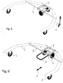
- Fig. 1 shows a furniture 1 that is especially suitable for use in a garden, on a terrace and the like. Use is not limited to outdoor use, indoor use is possible as well.
- the furniture 1 of Fig. 1 is embodied as a windscreen in a partially circular shape, wherein wheels at positions 2, 3, 4 are provided for carrying and moving the furniture 1. Wheels at positions 2, 3 are positioned such that these substantially follow a track of an imaginary circle 5. Wheel at position 4, which optionally may be embodied as two or even more wheels, substantially follow said same track.
- wheels 2, 3, 4" where actually “wheels at positions 2, 3, 4" is meant. This merely is indicated this way so as to clarify the possibility that instead of a single wheel 2, a plurality of two, three or even more wheels is possible as well and is part of the invention. It is preferred that said multiplicity of wheels at position 4 are suspended and rotatable independently from each other.
- Wheel 4 is connected pivotably to furniture 1, more in particular to a main body 6. Wheels 2, 3 are connected to said main body 6 as well. Wheel 4 is pivotable around a vertical axis 7 (shown in Fig. 5, 6 , 7, 8 ) and thus determines the way furniture 1 moves. When wheel 4 is in a position as shown in Fig. 1, 2, 3 the furniture can be rotated around rotation axis 8 in the direction of arrow 10 in Fig. 3 and 5 . However, when wheel 4 is in a position as shown in Fig. 4 , 6 and 7 the furniture can be relocated in the direction indicated by the arrow 9 in Fig. 4 and 6 .
- Fig. 2 indicates an embodiment of furniture 1 wherein seats 11 are provided at the furniture.
- the seats 11 are positioned such that users are facing inward, i.e. towards the center of rotation of the imaginary circle 5.
- the seats are shown in Fig. 3 and 4 as well.
- Seats 11 are preferably connected to the main body 6.
- the main body 6 is connected to a wall 12.
- the wall 12 may embody the main body 6.
- Such embodiment of the invention is also embodied by the phrase "a furniture, comprising a main body" of claim 1.
- the wall 12 and the seats 11 may be mutually connected embodying the main body 6.
- the wheels may be connected to the seats 11 or to the wall 12.
- the pivotable wheel 4 has a control lever 13 for pivoting same in the direction of arrow 14 with respect to said main body 6.
- said control lever has an extendable handle 15.
- Handle 15 can be embodied as a removable handle, wherein free ends of said handle can be inserted in holes 23.
- Fig. 5, 6 , 7, 8 show a sub-frame 16 carrying the wheel 4, forming part of main body 6.
- the sub-frame 16 has a first frame part 17 rigidly connected to wheel 4.
- First frame part 17 is pivotably coupled to second frame part 18, said second frame part being rigidly connected to said sub-frame 16.
- wheel 4 can be pivoted with respect to said main body 6.
- coupling pins 19 are inserted in receiving holes 20 and 21, respectively of first frame part 17 and in holes 22 of second frame part 18.
- the invention also relates to all other combinations of features described here independently of each other.
Landscapes
- Engineering & Computer Science (AREA)
- Mechanical Engineering (AREA)
- Legs For Furniture In General (AREA)
Abstract
The invention relates to a construction (1), comprising a main body (6) and wheels (2, 3, 4) for supporting and relocating said construction, wherein the wheels comprise at least one wheel (4) that is coupled pivotably to said main body and other wheels (2, 3) that are optionally coupled pivotably to said main body, wherein said main body (6) is embodied as an imaginary circle or imaginary partial circle, said other wheels (2, 3) being positioned at a substantially same distance from a center of said circle.The construction may for example be a piece of furniture or a shelter for housing animals, for example a coop.
Description
- The present invention relates to a movable construction according to the preamble of
claim 1. The construction according to the present invention is especially suitable for use as garden furniture. According to a further aspect, the present invention also relates to a steering wheel for use with the construction according to the present invention. - The construction according to the present invention is especially applicable as furniture, but is not limited thereto. The description will mainly use the term furniture, whereas other applications are meant and envisaged as well, as will become clear when reading the present description.
- It is known in the art to use furniture, both indoors and outdoors. Especially furniture that is used outdoors requires frequent relocation due to changing weather conditions.
- It is a cumbersome exercise to relocate outdoor furniture due to its high weight and large size.
- At present, there is no solution available for this drawback, except using many people to carry the furniture around. However, especially for elderly it remains difficult or even impossible to regularly relocate furniture.
- The invention therefore aims at providing an improved construction, in particular improved furniture, of the kind mentioned in the preamble.
- The invention further aims at providing a construction, for example but not limited to furniture, that allows elderly as well as singles of all ages to relocate same as they please, no matter how often they want it.
- So as to obtain at least one of the above mentioned aims, the invention provides a construction as mentioned in
claim 1. This construction has the advantage that it can be relocated, independent the physical situation of the person aiming to use the construction. - It has also shown that the construction according to the present invention provides joy to children (and even adults) who like to take a tour with the piece of construction, especially but not only when the construction is embodied as furniture. Such synergistic effect is a surprising and advantageous effect.
- The present thus relates to a construction, comprising a main body and wheels for supporting and relocating said construction, wherein the wheels comprise at least one wheel that is coupled pivotably to said main body and other wheels that are optionally coupled pivotably to said main body, wherein said main body is embodied as an imaginary circle or imaginary partial circle, said other wheels being positioned at a substantially same distance from a center of said circle. This embodiment allows a user to rotate the complete construction when the rotation axis of the pivotable wheels is directed towards the center of said circle and to relocate the construction when the rotation axis is perpendicular to that direction. When said other legs are in a fixed position, these other wheels must be positioned parallel and thus must have the same rotation axis, so as to enable an easy relocation of the construction.
- It is preferred that said construction comprises fixing means for fixing said pivotable wheel with respect to said main body in a non-pivotable manner. The pivotable wheel then can be placed in a position such that a relocation or rotation is not possible allowing for a more comfortable use.
- As indicated above, it is especially preferable for the construction wherein said main body has a partially imaginary circular shape with a middle portion and legs extending therefrom, wherein said construction comprises a wheel at each of said legs and a wheel at a position near said middle portion, wherein said wheels at said respective legs are positioned parallelly with respect to each other and said wheel at said middle portion is comprised of said pivotable wheel.
- More in particular, when said wheels at said respective legs have a rotation axis that extends through a center of said circular shape and wherein a pivot axis of said pivotable wheel is positioned at a normal line through said center of said circular shape, and wherein each of said wheels at said respective legs is positioned at a substantially same distance from said center, a very easy way of relocating and rotating said furniture is obtained.
- The construction according to the invention is especially adapted for easy use, when said construction comprises seating elements facing towards the inside of said circular shape, allowing to use the construction as a piece of furniture.
- An optimum protection against wind or peeking is obtained when said construction comprises a wall at at least part of said circular shape. The construction can be rotated to such position that others may not have a clear sight at people using the construction, for example as furniture. Also, especially by rotating the construction such that said wall is directed towards publicly accessible area, a user is shielded optimally from unwanted views.
- When the construction according to the invention comprises an at least partially disk-shaped platform covering at least part of said imaginary circle or imaginary partial circle, one can easily stand on said platform which is especially favorable when the ground is grassy, muddy, wet or otherwise not easily accessible. place his own seating elements thereon, for example chairs and tables.
- It is especially preferred if said construction according to the invention comprises a wall that is set up near a circumference of said platform.
- Analogously, it is preferred that said platform is embodied for carrying any of a table and a chair as indicated above.
- An easy way of rotating and relocating the construction according to the invention is obtained when the pivotable wheel has a control lever for pivoting same with respect to said main body.
- More preferably, said control lever has an extendable handle.
- Finally, it is preferred that the construction according to the invention comprises a roof, so as to shield people or animals using the construction from the weather, for example sun or rain.
- Hereafter, the invention will be further described by means of a drawing. The drawing shows in:
-
Fig. 1 and 2 show a perspective view of the construction according to the invention, -
Fig. 3 and 4 show a top view of the construction according to the invention, -
Fig. 5 and 6 show a perspective view of part of the construction according to the invention, and -
Fig. 7 and 8 show a detailed view of a pivotable wheel for use in the construction according to the invention. - The same and similar parts and features have been denoted by the same reference numerals in the figures. However, for ease of understanding the figures, not all parts that are required for a practical embodiment have been shown in the figures. The invention will hereafter be referred to as a piece of furniture, although the invention is not limited thereto. The construction may be used as a shelter for animals, for example as a coop.
-
Fig. 1 shows afurniture 1 that is especially suitable for use in a garden, on a terrace and the like. Use is not limited to outdoor use, indoor use is possible as well. Thefurniture 1 ofFig. 1 is embodied as a windscreen in a partially circular shape, wherein wheels atpositions furniture 1. Wheels atpositions 2, 3 are positioned such that these substantially follow a track of animaginary circle 5. Wheel atposition 4, which optionally may be embodied as two or even more wheels, substantially follow said same track. By applying a set of threepositions furniture 1 is obtained. - Hereafter, reference will be made to "
wheels positions single wheel 2, a plurality of two, three or even more wheels is possible as well and is part of the invention. It is preferred that said multiplicity of wheels atposition 4 are suspended and rotatable independently from each other. -
Wheel 4 is connected pivotably tofurniture 1, more in particular to a main body 6.Wheels 2, 3 are connected to said main body 6 as well.Wheel 4 is pivotable around a vertical axis 7 (shown inFig. 5, 6 ,7, 8 ) and thus determines theway furniture 1 moves. Whenwheel 4 is in a position as shown inFig. 1, 2, 3 the furniture can be rotated aroundrotation axis 8 in the direction ofarrow 10 inFig. 3 and5 . However, whenwheel 4 is in a position as shown inFig. 4 ,6 and7 the furniture can be relocated in the direction indicated by thearrow 9 inFig. 4 and6 . -
Fig. 2 indicates shows an embodiment offurniture 1 wherein seats 11 are provided at the furniture. The seats 11 are positioned such that users are facing inward, i.e. towards the center of rotation of theimaginary circle 5. The seats are shown inFig. 3 and 4 as well. Seats 11 are preferably connected to the main body 6. - In
Fig. 1 , the main body 6 is connected to awall 12. As a matter of fact, in accordance with the present invention, thewall 12 may embody the main body 6. Such embodiment of the invention is also embodied by the phrase "a furniture, comprising a main body" ofclaim 1. Analogously, thewall 12 and the seats 11 may be mutually connected embodying the main body 6. In such case, the wheels may be connected to the seats 11 or to thewall 12. - In
Fig. 3 , thepivotable wheel 4 has acontrol lever 13 for pivoting same in the direction of arrow 14 with respect to said main body 6. - As shown in
Fig. 6 , said control lever has anextendable handle 15.Handle 15 can be embodied as a removable handle, wherein free ends of said handle can be inserted inholes 23. -
Fig. 5, 6 ,7, 8 show asub-frame 16 carrying thewheel 4, forming part of main body 6. Thesub-frame 16 has a first frame part 17 rigidly connected towheel 4. First frame part 17 is pivotably coupled to second frame part 18, said second frame part being rigidly connected to saidsub-frame 16. As a result,wheel 4 can be pivoted with respect to said main body 6. So as to maintain saidwheel 4 in one of said positions indicated inFig. 7 and Fig. 8 , coupling pins 19 are inserted in receivingholes holes 22 of second frame part 18. - The invention is not limited to the embodiments as mentioned above and as shown in the drawings. The invention is limited by the claims only.
- The invention also relates to all other combinations of features described here independently of each other.
Claims (13)
- A construction, comprising a main body and wheels for supporting and relocating said construction, wherein the wheels comprise at least one wheel that is coupled pivotably to said main body and other wheels that are optionally coupled pivotably to said main body, wherein said main body is embodied as an imaginary circle or imaginary partial circle, said other wheels being positioned at a substantially same distance from a center of said circle.
- A construction according to claim 1, wherein said construction comprises fixing means for fixing said pivotable wheel with respect to said main body in a non-pivotable manner.
- A construction according to claim 1 or 2, wherein said main body has a partially imaginary circular shape with a middle portion and legs extending therefrom, wherein said construction comprises a wheel at each of said legs and a wheel at a position near said middle portion, wherein said wheels at said respective legs are positioned parallelly with respect to each other and said wheel at said middle portion is comprised of said pivotable wheel.
- A construction according to claim 3, wherein said wheels at said respective legs have a rotation axis that extends through a center of said circular shape and wherein a pivot axis of said pivotable wheel is positioned at a normal line through said center of said circular shape, wherein each of said wheels at said respective legs is positioned at a substantially same distance from said center.
- A construction according to claim 1, wherein said construction comprises seating elements facing towards the inside of said circular shape.
- A construction according to claim 1, wherein said construction comprises walls at at least part of said circular shape.
- A construction according to claim 1, comprising an at least partially disk-shaped platform covering at least part of said imaginary circle or imaginary partial circle.
- A construction according to claim 7, wherein a wall is set up near a circumference of said platform.
- A construction according to claim 7, wherein said platform is embodied for carrying any of a table and a chair.
- A construction according to claim 1, wherein the pivotable wheel has a control lever for pivoting same with respect to said main body.
- A construction according to claim 10, wherein said control lever has an extendable handle.
- A construction according to any of the preceding claims, comprising a roof.
- A construction according to any of claims 1-12, embodied as a shelter for housing animals, for example a coop.
Priority Applications (1)
| Application Number | Priority Date | Filing Date | Title |
|---|---|---|---|
| EP18156099.6A EP3524441A1 (en) | 2018-02-09 | 2018-02-09 | A movable construction |
Applications Claiming Priority (1)
| Application Number | Priority Date | Filing Date | Title |
|---|---|---|---|
| EP18156099.6A EP3524441A1 (en) | 2018-02-09 | 2018-02-09 | A movable construction |
Publications (1)
| Publication Number | Publication Date |
|---|---|
| EP3524441A1 true EP3524441A1 (en) | 2019-08-14 |
Family
ID=61223716
Family Applications (1)
| Application Number | Title | Priority Date | Filing Date |
|---|---|---|---|
| EP18156099.6A Withdrawn EP3524441A1 (en) | 2018-02-09 | 2018-02-09 | A movable construction |
Country Status (1)
| Country | Link |
|---|---|
| EP (1) | EP3524441A1 (en) |
Citations (5)
| Publication number | Priority date | Publication date | Assignee | Title |
|---|---|---|---|---|
| GB187698A (en) * | 1921-07-22 | 1922-10-23 | Salt S Textile Company De Fran | Improvements in or relating to display stands for textile goods or the like |
| DE29608502U1 (en) * | 1996-05-10 | 1996-08-01 | Chung, Chin-Fu, Tainan | Spring-loaded swivel castor |
| US20040060588A1 (en) * | 2001-08-27 | 2004-04-01 | David Lekhtman | Beach kiosk |
| US20150014964A1 (en) * | 2013-01-30 | 2015-01-15 | Penta Mobility, Inc. | Ambulatory Assistance Device |
| US20160263311A1 (en) * | 2010-11-01 | 2016-09-15 | Notion Medical Inc. | Carrier for Patient Fluids |
-
2018
- 2018-02-09 EP EP18156099.6A patent/EP3524441A1/en not_active Withdrawn
Patent Citations (5)
| Publication number | Priority date | Publication date | Assignee | Title |
|---|---|---|---|---|
| GB187698A (en) * | 1921-07-22 | 1922-10-23 | Salt S Textile Company De Fran | Improvements in or relating to display stands for textile goods or the like |
| DE29608502U1 (en) * | 1996-05-10 | 1996-08-01 | Chung, Chin-Fu, Tainan | Spring-loaded swivel castor |
| US20040060588A1 (en) * | 2001-08-27 | 2004-04-01 | David Lekhtman | Beach kiosk |
| US20160263311A1 (en) * | 2010-11-01 | 2016-09-15 | Notion Medical Inc. | Carrier for Patient Fluids |
| US20150014964A1 (en) * | 2013-01-30 | 2015-01-15 | Penta Mobility, Inc. | Ambulatory Assistance Device |
Similar Documents
| Publication | Publication Date | Title |
|---|---|---|
| US6276382B1 (en) | Adjustable canopy and pivotable picnic table | |
| US6178978B1 (en) | Children's activity and entertainment enclosure | |
| US20230000238A1 (en) | Rotary hanging chair | |
| US8517472B1 (en) | Adjustable foot-rest chair ring | |
| US20140183909A1 (en) | Lounge Chair Having Adjustable Armrests | |
| US20200376315A1 (en) | Modular Play Set | |
| US7326152B2 (en) | Infant walker | |
| US20070102976A1 (en) | Portable sports bench | |
| EP3524441A1 (en) | A movable construction | |
| US7748786B1 (en) | Footrest | |
| CN110870639B (en) | Footrest for chairs and armchairs | |
| US9675177B1 (en) | Chair leg extension apparatus to level chair on an uneven ground | |
| US7931564B1 (en) | Assembled rock climbing device | |
| US9908002B2 (en) | Portable, collapsible ergonomic tipping chair | |
| CN210611621U (en) | A type II seat suitable for aging landscape area | |
| AU2007100069B4 (en) | Game box | |
| KR200197312Y1 (en) | Round table having function of ping-pong table | |
| CN212617437U (en) | Strutting arrangement for artifical forest reconnaissance appearance | |
| CN218304122U (en) | A multifunctional garden leisure chair | |
| US20240081545A1 (en) | System and Method for a Backrest | |
| CN217908975U (en) | Turnover plate multi-angle adjusting and positioning structure and fun house with same | |
| CN208769269U (en) | Removable child support and entertainment device | |
| US12588766B2 (en) | Seat comprising a frame and a cover, and method of manufacturing the same | |
| CN224038818U (en) | Hardware sofa foot with adjusting structure | |
| CN207506234U (en) | Multipurpose stealth seat |
Legal Events
| Date | Code | Title | Description |
|---|---|---|---|
| PUAI | Public reference made under article 153(3) epc to a published international application that has entered the european phase |
Free format text: ORIGINAL CODE: 0009012 |
|
| STAA | Information on the status of an ep patent application or granted ep patent |
Free format text: STATUS: THE APPLICATION HAS BEEN PUBLISHED |
|
| AK | Designated contracting states |
Kind code of ref document: A1 Designated state(s): AL AT BE BG CH CY CZ DE DK EE ES FI FR GB GR HR HU IE IS IT LI LT LU LV MC MK MT NL NO PL PT RO RS SE SI SK SM TR |
|
| AX | Request for extension of the european patent |
Extension state: BA ME |
|
| STAA | Information on the status of an ep patent application or granted ep patent |
Free format text: STATUS: THE APPLICATION IS DEEMED TO BE WITHDRAWN |
|
| 18D | Application deemed to be withdrawn |
Effective date: 20200215 |