EP3524439A1 - Image forming method and image forming system - Google Patents
Image forming method and image forming system Download PDFInfo
- Publication number
- EP3524439A1 EP3524439A1 EP17858310.0A EP17858310A EP3524439A1 EP 3524439 A1 EP3524439 A1 EP 3524439A1 EP 17858310 A EP17858310 A EP 17858310A EP 3524439 A1 EP3524439 A1 EP 3524439A1
- Authority
- EP
- European Patent Office
- Prior art keywords
- ink
- recording medium
- image
- discharge treatment
- outermost surface
- Prior art date
- Legal status (The legal status is an assumption and is not a legal conclusion. Google has not performed a legal analysis and makes no representation as to the accuracy of the status listed.)
- Granted
Links
Images


Classifications
-
- B—PERFORMING OPERATIONS; TRANSPORTING
- B41—PRINTING; LINING MACHINES; TYPEWRITERS; STAMPS
- B41J—TYPEWRITERS; SELECTIVE PRINTING MECHANISMS, i.e. MECHANISMS PRINTING OTHERWISE THAN FROM A FORME; CORRECTION OF TYPOGRAPHICAL ERRORS
- B41J11/00—Devices or arrangements of selective printing mechanisms, e.g. ink-jet printers or thermal printers, for supporting or handling copy material in sheet or web form
- B41J11/0015—Devices or arrangements of selective printing mechanisms, e.g. ink-jet printers or thermal printers, for supporting or handling copy material in sheet or web form for treating before, during or after printing or for uniform coating or laminating the copy material before or after printing
-
- B—PERFORMING OPERATIONS; TRANSPORTING
- B41—PRINTING; LINING MACHINES; TYPEWRITERS; STAMPS
- B41J—TYPEWRITERS; SELECTIVE PRINTING MECHANISMS, i.e. MECHANISMS PRINTING OTHERWISE THAN FROM A FORME; CORRECTION OF TYPOGRAPHICAL ERRORS
- B41J13/00—Devices or arrangements of selective printing mechanisms, e.g. ink-jet printers or thermal printers, specially adapted for supporting or handling copy material in short lengths, e.g. sheets
- B41J13/0063—Handling thick cut sheets, e.g. greeting cards or postcards, larger than credit cards, e.g. using means for enabling or facilitating the conveyance of thick sheets
-
- B—PERFORMING OPERATIONS; TRANSPORTING
- B41—PRINTING; LINING MACHINES; TYPEWRITERS; STAMPS
- B41M—PRINTING, DUPLICATING, MARKING, OR COPYING PROCESSES; COLOUR PRINTING
- B41M5/00—Duplicating or marking methods; Sheet materials for use therein
- B41M5/0011—Pre-treatment or treatment during printing of the recording material, e.g. heating, irradiating
-
- B—PERFORMING OPERATIONS; TRANSPORTING
- B41—PRINTING; LINING MACHINES; TYPEWRITERS; STAMPS
- B41M—PRINTING, DUPLICATING, MARKING, OR COPYING PROCESSES; COLOUR PRINTING
- B41M7/00—After-treatment of prints, e.g. heating, irradiating, setting of the ink, protection of the printed stock
- B41M7/0081—After-treatment of prints, e.g. heating, irradiating, setting of the ink, protection of the printed stock using electromagnetic radiation or waves, e.g. ultraviolet radiation, electron beams
-
- C—CHEMISTRY; METALLURGY
- C09—DYES; PAINTS; POLISHES; NATURAL RESINS; ADHESIVES; COMPOSITIONS NOT OTHERWISE PROVIDED FOR; APPLICATIONS OF MATERIALS NOT OTHERWISE PROVIDED FOR
- C09D—COATING COMPOSITIONS, e.g. PAINTS, VARNISHES OR LACQUERS; FILLING PASTES; CHEMICAL PAINT OR INK REMOVERS; INKS; CORRECTING FLUIDS; WOODSTAINS; PASTES OR SOLIDS FOR COLOURING OR PRINTING; USE OF MATERIALS THEREFOR
- C09D11/00—Inks
- C09D11/02—Printing inks
- C09D11/10—Printing inks based on artificial resins
- C09D11/101—Inks specially adapted for printing processes involving curing by wave energy or particle radiation, e.g. with UV-curing following the printing
-
- C—CHEMISTRY; METALLURGY
- C09—DYES; PAINTS; POLISHES; NATURAL RESINS; ADHESIVES; COMPOSITIONS NOT OTHERWISE PROVIDED FOR; APPLICATIONS OF MATERIALS NOT OTHERWISE PROVIDED FOR
- C09D—COATING COMPOSITIONS, e.g. PAINTS, VARNISHES OR LACQUERS; FILLING PASTES; CHEMICAL PAINT OR INK REMOVERS; INKS; CORRECTING FLUIDS; WOODSTAINS; PASTES OR SOLIDS FOR COLOURING OR PRINTING; USE OF MATERIALS THEREFOR
- C09D11/00—Inks
- C09D11/30—Inkjet printing inks
- C09D11/38—Inkjet printing inks characterised by non-macromolecular additives other than solvents, pigments or dyes
-
- C—CHEMISTRY; METALLURGY
- C09—DYES; PAINTS; POLISHES; NATURAL RESINS; ADHESIVES; COMPOSITIONS NOT OTHERWISE PROVIDED FOR; APPLICATIONS OF MATERIALS NOT OTHERWISE PROVIDED FOR
- C09D—COATING COMPOSITIONS, e.g. PAINTS, VARNISHES OR LACQUERS; FILLING PASTES; CHEMICAL PAINT OR INK REMOVERS; INKS; CORRECTING FLUIDS; WOODSTAINS; PASTES OR SOLIDS FOR COLOURING OR PRINTING; USE OF MATERIALS THEREFOR
- C09D11/00—Inks
- C09D11/30—Inkjet printing inks
- C09D11/34—Hot-melt inks
Definitions
- (meth)acrylate examples include monofunctional (meth)acrylates such as isoamyl (meth)acrylate, stearyl (meth)acrylate, lauryl (meth)acrylate, octyl (meth)acrylate, decyl (meth)acrylate, isomyristyl (meth)acrylate, isostearyl (meth)acrylate, 2-ethylhexyl-diglycol (meth)acrylate, 2-hydroxybutyl (meth)acrylate, 2-(meth)acryloyloxyethyl hexahydrophthalic acid, butoxyethyl (meth)acrylate, ethoxydiethylene glycol (meth)acrylate, methoxydiethylene glycol (meth)acrylate, methoxypolyethylene glycol (meth)acrylate, methoxypropylene glycol (meth)acrylate, phenoxyethyl (meth)acrylate, tetrahydrofurfury
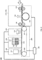
- FIGS. 2 and 3 are side views illustrating the concept of inkjet image forming system 200 according to the present embodiment.
- the C pigment dispersion was mixed with respective components listed below in accordance with the composition of each ink shown in Table 1 below, and the resultant was heated to 80°C and stirred.
- the solution thus obtained was filtered, under heating, through a Teflon (R) membrane filter (5 ⁇ m) manufactured by ADVANTEC Co., Ltd. to obtain each of inks C1 to C5.
- the gelling temperature (Tgel) (°C) of each ink prepared as described above was measured in the following manner: The ink was heated to 100°C, and then cooled to 20°C under conditions of a shear rate of 11.7/s and a temperature decrease rate of 0.1°C/s to obtain a temperature-dependent viscosity change curve through measurement with a rheometer. A temperature, on the temperature-dependent viscosity change curve thus obtained, at which the viscosity is 200 mPa ⁇ s was obtained as the gelling temperature.
- a stress controlled rheometer Physica MCR series manufactured by Anton Paar Gmbh was used with a cone plate diameter set to 75 mm and a cone angle set to 1.0°.
- the gelling temperatures of the respective inks are shown in Table 1.
- timing of ejecting the ink was adjusted so that a time interval from the discharge treatment to the irradiation with the actinic radiation could be a time shown in Table 4, 5 or 6.
Landscapes
- Chemical & Material Sciences (AREA)
- Life Sciences & Earth Sciences (AREA)
- Engineering & Computer Science (AREA)
- Materials Engineering (AREA)
- Wood Science & Technology (AREA)
- Organic Chemistry (AREA)
- Physics & Mathematics (AREA)
- Health & Medical Sciences (AREA)
- Electromagnetism (AREA)
- General Health & Medical Sciences (AREA)
- Toxicology (AREA)
- Ink Jet Recording Methods And Recording Media Thereof (AREA)
- Ink Jet (AREA)
- Inks, Pencil-Leads, Or Crayons (AREA)
Abstract
Description
- The present invention relates to an image forming method and an image forming system.
- An inkjet method is employed in a variety of fields of printing because images can be simply and inexpensively formed by this method.
- Inks used for forming images by the inkjet method are classified into several types of inks such as a water-based ink containing water and optionally a small amount of an organic solvent as a liquid component, a solvent-based ink containing an organic solvent as a liquid component but containing substantially no water, and an actinic radiation-curable ink containing, as a liquid component, a photocurable compound that is cured by polymerization and crosslinking through irradiation with actinic radiation after printing, and these inks are used in accordance with the intended use. An image forming method using the actinic radiation-curable ink has a feature that images having high adhesion can be formed regardless of water absorbability of the recording medium.
- As a kind of the actinic radiation-curable ink, an ink containing a gelling agent for reversibly undergoing sol-gel phase transition in accordance with change in temperature (hereinafter sometimes simply referred to as the "gel ink") has been developed. The gel ink has a feature that wetting and spreading of the ink can be easily controlled because after the ink heated to a sol state is ejected from a nozzle of an inkjet head and lands on the surface of a recording medium, the ink is cooled to undergo gelation to be pinned thereon. When the gel ink thus pinned on the surface of the recording medium is irradiated with actinic radiation, the gel ink is cured to form an image.
- In recent years, attempts have been made to apply image formation by the inkjet method to various types of recording media. For example, PTL 1 describes that an image can be formed also on a recording medium having a corrugated surface such as a corrugated cardboard by using a gel ink containing a gelling agent having an alkyl group and an amide group having about 50 carbon atoms.
- On the other hand, for a recording medium having low ink absorbability, there is a known method in which surface energy of the surface of the recording medium is increased through a corona treatment, a plasma treatment or the like for making the ink having landed thereon easily wet and spread to a sufficient dot diameter.
- For example, PTL 2 describes a method for forming an image, by using a gel ink, on a polyethylene terephthalate (PET) film having been subjected to a corona treatment immediately before printing. Besides, PTL 3 and PTL 4 describe an image forming apparatus for forming an image using a water-based ink including a corona treatment part or a plasma treatment part for increasing surface energy of a recording medium.
-
- PTL 1:
U.S. Patent Application Publication No. 2008/0204538 - PTL 2: Japanese Patent Application Laid-Open No.
2014-159114 - PTL 3: Japanese Patent Application Laid-Open No.
2015-143003 - PTL 4: Japanese Patent Application Laid-Open No.
2015-180529 - PTL 1 discloses that an image can be formed on a recording medium of a corrugated cardboard or the like using a gel ink. According to the finding of the present inventor, however, when an image was formed on a recording medium of a corrugated cardboard or the like using a gel ink as described in PTL 1, the resultant image sometimes became uneven because some dots of the image were lost and hence the image could not be completely formed or gradation could not be smoothly expressed.
- Such a problem is probably caused because the surface energy of the recording medium was so small that the wetting and spreading of the ink having landed thereon was insufficient. When an image was formed, using a gel ink, on a recording medium of a corrugated cardboard or the like having surface energy increased through a discharge treatment described in PTLs 2 to 4, however, a refined image was difficult to form because of excessive wetting and spreading of the ink.
- The present invention was devised in consideration of the above-described problem, and an object is, in forming an image on a recording medium of a corrugated cardboard or the like by the inkjet method using a gel ink, to provide an image forming method in which a more refined image can be formed with image unevenness suppressed, and an image forming system capable of practicing the image forming method.
- The present invention is to solve the problem mentioned above by the following means.
- [1] An image forming method, comprising:
- subjecting, to a discharge treatment with a dosage of 10 W·min/m2 or more and 200 W·min/m2 or less, an outermost surface on which an image is to be formed of a liner of a recording medium corresponding to a corrugated cardboard including a corrugating medium and the liner;
- heating the recording medium subjected to the discharge treatment;
- ejecting a droplet of an actinic radiation-curable inkjet ink from a nozzle of an inkjet head within 60 seconds after the discharge treatment, the actinic radiation-curable inkjet ink containing a photocurable compound and a gelling agent having an alkyl group having 12 or more and 26 or less carbon atoms and to undergo sol-gel phase transition depending on temperature, and allowing the droplet to land on the outermost surface of the heated recording medium subjected to the discharge treatment; and
- irradiating the droplet having landed on the outermost surface with actinic radiation.
- [2] The image forming method according to [1], wherein the gelling agent is a compound selected from the group consisting of a compound represented by formula (G1) and a compound represented by formula (G2):
formula (G1): R1-CO-R2
formula (G2): R3-COO-R4
wherein R1, R2, R3 and R4 all represent a hydrocarbon group having a straight chain portion having 12 or more and 26 or less carbon atoms and optionally having a branched chain. - [3] The image forming method according to [1] or [2], wherein the heating is performed in such a manner that a temperature of the outermost surface of the liner is lower than a gelling temperature of the ink by 5°C or more and 25°C or less.
- [4] The image forming method according to any one of [1] to [3], wherein the heating is performed from a side of the outermost surface of the liner of the recording medium.
- [5] The image forming method according to any one of [1] to [4], wherein the heating is performed from a side of the outermost surface of the liner of the recording medium and a side of a surface opposite to the outermost surface.
- [6] An image forming system, comprising:
- a discharge treatment section that subjects, to a discharge treatment with a dosage of 10 W·min/m2 or more and 200 W·min/m2 or less, an outermost surface on which an image is to be formed of a liner of a recording medium corresponding to a corrugated cardboard including a corrugating medium and the liner;
- a heating section that heats the recording medium subjected to the discharge treatment;
- an ink ejection section that ejects a droplet of an actinic radiation-curable inkjet ink from a nozzle of an inkjet head, the actinic radiation-curable inkjet ink containing a photocurable compound and a gelling agent having an alkyl group having 12 or more and 26 or less carbon atoms to undergo sol-gel phase transition depending on temperature, and allows the droplet to land on the outermost surface of the heated recording medium subjected to the discharge treatment;
- an actinic radiation irradiation section that irradiates the droplet having landed on the outermost surface with actinic radiation;
- a conveyance section that conveys the recording medium; and
- a control section that controls a conveying speed of the recording medium by the conveyance section in such a manner that the ink ejection section ejects the droplet of the inkjet ink within 60 seconds after the discharge treatment performed by the discharge treatment section.
- According to the present invention, in forming an image on a recording medium of a corrugated cardboard or the like by the inkjet method using a gel ink, an image forming method in which a more refined image can be formed with image unevenness suppressed, and an image forming system capable of practicing the image forming method are provided.
-
-
FIG. 1 is a schematic side view illustrating a corona treatment apparatus usable in one embodiment of the present invention. -
FIG. 2 is a schematic side view illustrating a system for forming an image by an inkjet method usable in one embodiment of the present invention. -
FIG. 3 is a schematic side view illustrating another system for forming an image by the inkjet method usable in one embodiment of the present invention. - According to earnest studies made by the present inventor, image unevenness can be further suppressed and a more refined image can be formed by an image forming method including: subjecting, to a discharge treatment with a dosage of 10 W·min/m2 or more and 200 W·min/m2 or less, an outermost surface on which an image is to be formed of a liner of a recording medium corresponding to a corrugated cardboard including a corrugating medium and the liner; heating the recording medium subjected to the discharge treatment; ejecting a droplet of an actinic radiation-curable inkjet ink from a nozzle of an inkjet head within 60 seconds after the discharge treatment, the actinic radiation-curable inkjet ink containing a photocurable compound and a gelling agent having an alkyl group having 12 or more and 26 or less carbon atoms to undergo sol-gel phase transition depending on temperature, and allowing the droplet to land on the outermost surface of the heated recording medium subjected to the discharge treatment; and irradiating the droplet having landed on the outermost surface with actinic radiation.
- According to the examination made by the present inventor, the water-based inks described in PTL 3 and PTL 4 have higher polarity than an actinic radiation-curable ink and are difficult to cause wetting and spreading on a recording medium. Besides, the films described in PTL 3 and PTL 4 have lower wettability than a corrugated cardboard and are difficult to cause wetting and spreading of an ink. When the wetting and spreading of an ink is difficult to cause, a gap having no ink adhesion (dot missing) may be caused between dots. Besides, since a large number of irregularities are formed owing to a corrugating medium on a surface of a corrugated cardboard, there are, along the irregularities of the surface, a region where an ink easily flows and a region where the ink is difficult to flow. Therefore, in forming an image on a corrugated cardboard, if the wetting and spreading of an ink is difficult to cause, a difference in pigment density due to the flow of the ink is easily formed in an image. Accordingly, in order to make unevenness difficult to cause in an image by the method described in PTL 3 or PTL4, it is necessary to further increase the surface energy of the recording medium.
- When the surface energy is increased in the same manner as in PTL 3 and PTL 4 in forming an image on a corrugated cardboard having higher ink wettability than a film by using an actinic radiation-curable ink having lower polarity, however, the wetting and spreading of the ink is unavoidably excessively caused. When the wetting and spreading of an ink is excessively caused, the resolution of a resultant image is lowered, and hence a refined image is difficult to form. Therefore, in forming an image on a corrugated cardboard by using an actinic radiation-curable ink, the increase of the surface energy of the recording medium needs to be set lower than that described in PTL 3 and PTL 4.
- It is, however, difficult to increase the surface energy of a recording medium having a hollow structure like a corrugated cardboard even through a corona treatment or the like, and hence, it is more difficult to adjust the extent of the corona treatment or the like for obtaining surface energy suitable for the actinic radiation-curable ink not containing a gelling agent. Besides, when the increase of the surface energy is smaller, the surface energy increased by the corona treatment or the like is lost faster, and therefore, the degree of freedom in apparatus structure is decreased, and an image forming rate is more difficult to adjust.
- On the contrary, when an appropriate type of gel ink is used, even if the surface energy is increased to easily cause the wetting and spreading of the ink, the ink is pinned when appropriately wet and spread, and thus excessive wetting and spreading of the ink is suppressed, and hence the dosage of the corona treatment or the like can be more freely set. Besides, when the gel ink is used, even if there is a difference in easiness in causing the wetting and spreading of the ink due to irregularities on a surface, since the excessive wetting and spreading can be suppressed by pinning, unevenness derived from irregularities owing to a corrugating medium can be difficult to occur.
- When a recording medium is warmed for adjusting a time up to pinning by a gelling agent, the surface energy increased by a corona treatment or the like is easily lowered as time passes. Therefore, when an image is formed on a recording medium of a corrugated cardboard or the like using a gel ink, it is necessary to perform adjustment so that the surface energy can be sufficiently increased also when the gel ink lands thereon.
- On the contrary, when the surface energy of a recording medium of a corrugated cardboard or the like is appropriately increased by a corona treatment or the like and an image is formed by ejecting the gel ink onto the recording medium within 60 seconds after the corona treatment or the like, the wetting and spreading of the ink can be sufficiently controlled. When the surface energy is appropriately increased and an image is formed with the surface energy increased in this manner, it is presumed that the wetting and spreading of the ink is sufficiently caused so as to form an image with less unevenness. On the other hand, since a rate of causing gelation of the ink by a gelling agent can be adjusted by heating the recording medium, the excessive wetting and spreading of the ink is also probably difficult to occur.
- As described so far, when the dosage of the discharge treatment, the type of the gelling agent, whether or not a recording medium is heated, and a treatment time up to curing of the ink by irradiation with actinic radiation after the discharge treatment are all controlled in an appropriate combination, it is presumed that the unevenness of an image is more difficult to occur and a more refined image can be formed.
- One embodiment of the present invention relates to a method for forming an image on a corrugated cardboard using a gel ink. The method includes, in the following order:
- (1) subjecting, to a discharge treatment with a dosage of 10 W·min/m2 or more and 200 W·min/m2 or less, an outermost surface on which an image is to be formed of a liner of a recording medium corresponding to a corrugated cardboard including a corrugating medium and the liner (hereinafter sometimes simply referred to as the "discharge treatment step");
- (2) heating the recording medium subjected to the discharge treatment (hereinafter sometimes simply referred to as the "heating step");
- (3) ejecting a droplet of a gel ink from a nozzle of an inkjet head, the gel ink containing a gelling agent having an alkyl group having 12 or more and 26 or less carbon atoms, and allowing the droplet to land on the outermost surface of the heated recording medium subjected to the discharge treatment (hereinafter sometimes simply referred to as the "landing step"); and
- (4) irradiating the droplet having landed on the outermost surface with actinic radiation (hereinafter sometimes simply referred to as the "actinic radiation irradiating step").
- In the discharge treatment step, the outermost surface on which an image is to be formed of the liner of the recording medium corresponding to a corrugated cardboard including a corrugating medium and the liner is subjected to the discharge treatment with a dosage of 10 W·min/m2 or more and 200 W·min/m2 or less.
- The recording medium is a corrugated cardboard. The corrugated cardboard is a laminate including a corrugating medium formed by molding a cardboard or the like into a corrugated shape, and a liner forming an outermost surface. The corrugated cardboard may be a double-sided corrugated cardboard including liners sandwiching both surfaces of a corrugating medium or a single-sided corrugated cardboard including a liner provided only on one surface of a corrugating medium. Alternatively, the corrugated cardboard may be a reinforced corrugated cardboard, such as a double wall corrugated cardboard including double corrugating media or a triple wall corrugated cardboard including triple corrugating media, as long as it is applicable to an apparatus or a system for forming an image by the inkjet method (hereinafter sometimes simply referred to as the "image forming apparatus" or the "image forming system", respectively).
- Materials of the corrugating medium and the liner are not especially limited, and are preferably paper, and may be any of known materials including a cardboard including lamination of recycled paper and kraft pulp. The corrugating medium may be, for example, a cardboard including multiple layers of recycled paper molded into a corrugated shape, such as an ordinary corrugating medium and a reinforced corrugating medium. Besides, the liner may be made from a kraft liner (K liner), a jute liner (C liner) or the like.
- The corrugated cardboard may have a thickness applicable to the image forming system. From the viewpoint of handleability, micro flute including E flute, F flute and G flute is preferred.
- In the corrugated cardboard, an image is formed on the outermost surface of the liner (the surface thereof not facing the corrugating medium).
- The discharge treatment is performed on the outermost surface on which an image is to be formed of the liner.
- The discharge treatment may be performed by a known method. For example, while the corrugated cardboard is being conveyed on a dielectric roll having a surface made of an insulating dielectric, discharge may be caused from an electrode toward the dielectric roll. The electrode can be a metal electrode, a ceramic electrode or the like. The dielectric can be made of silicon, ceramic, stainless steel or the like.
- The discharge treatment can be performed by, for example,
corona treatment apparatus 100 having a structure in which recording medium P (corrugated cardboard) having been conveyed onstage 110 is conveyed ondielectric roll 150 provided to opposeelectrode 140 between feedingroller 120 and receivingroller 130 as illustrated inFIG. 1 . At this point, a voltage is applied byAC power supply 160 betweenelectrode 140 anddielectric roll 150 to cause discharge, and recording medium P corresponding to the corrugated cardboard is conveyed on the dielectric roll with the outermost surface of the liner disposed to face the electrode, and thus, the outermost surface of the liner is subjected to the discharge treatment. - The dosage obtained at this point is calculated in accordance with the following expression:

In the expression, - L is a length (m) of a discharge electrode,
- V is a conveying speed (m/min) of the recording medium, and
- P is discharge power (W).
- The length of the discharge electrode, the conveying speed and the discharge power are adjusted so that the dosage can be 10 W·min/m2 or more and 200 W·min/m2 or less. Among these parameters, the discharge power that can be easily changed is preferably changed to adjust the dosage to fall in the above-described range. When the dosage is 10 W·min/m2 or more, the surface energy of the outermost surface is so sufficiently increased that the wetting and spreading of the gel ink can be easily caused. When the dosage is 200 W·min/m2 or less, the surface energy of the outermost surface is not excessively increased and hence excessive wetting and spreading of the ink can be suppressed. From these points of view, the dosage is preferably 25 W·min/m2 or more and 100 W·min/m2 or less, and more preferably 25 W·min/m2 or more and 75 W·min/m2 or less.
- The conveying speed of the recording medium is not especially limited, and can be adjusted within a range of, for example, 1 m/min or more and 250 m/min or less, and is preferably 30 m/min or more and 200 m/min or less, more preferably 30 m/min or more and 120 m/min or less, and further preferably 55 m/min or more and 120 m/min or less.
- In the heating step, the recording medium subjected to the discharge treatment is heated.
- The surface temperature of the outermost surface can be adjusted by heating the recording medium. When the gel ink lands, in the subsequent step, on the outermost surface whose temperature has been adjusted, the ink having landed undergoes gelation after being appropriately wet and spread, and therefore, unevenness of image quality and occurrence of uneven gloss can be suppressed. On the contrary, when the gel ink is caused to land without heating the recording medium, the ink having landed is cooled by the recording medium before wetting and spreading, and hence immediately undergoes gelation to be pinned, and therefore, the unevenness of image quality is easily caused, and in addition, the surface of the ink having landed is not sufficiently smoothed (leveled) and hence uneven gloss is easily caused.
- From these points of view, the heating is performed in such a manner that the surface temperature of the outermost surface is lower than the gelling temperature of the gel ink by preferably 5°C or more and 25°C or less, and more preferably 5°C or more and 20°C or less. Besides, from the viewpoint of suppressing degradation of the recording medium otherwise caused through excessive heating, the heating is preferably performed in such a manner that the surface temperature of the outermost surface is 30°C or more and 50°C or less.
- For the heating, the recording medium can be heated, for example, through contact heating using a rubber heater, a warmed roller or the like, or through non-contact heating using infrared irradiation (IR irradiation), hot air blowing or the like.
- The heating may be performed from the side of the outermost surface of the recording medium, or may be performed from a side of a surface opposite to the outermost surface (rear surface). Since the corrugated cardboard has a large thickness and includes, in the corrugating medium portion, air difficult to conduct heat, however, if the heating is performed merely from the rear surface side, a necessary amount of heat may be large in some cases, and in addition, unevenness may be caused on the outermost surface after the heating. Therefore, from the viewpoint of improving heating efficiency and stably performing the heating, the heating is preferably performed at least from the side of the outermost surface of the recording medium, and the heating is more preferably performed from the side of the outermost surface in combination with heating from the rear surface side.
- From the viewpoint of adjusting the surface temperature of the outermost surface stably to 30°C or more and 50°C or less, when a contact heating method is employed, the temperature of a portion of a rubber heater, a roller or the like to be in contact with the outermost surface is preferably set to 50°C or more and 120 or less, and when the hot air blowing is employed, the temperature of blown air is preferably set to 70°C or more and 150°C or less.
- In the landing step, a droplet of the gel ink is ejected from a nozzle of an inkjet head to cause the droplet to land on the outermost surface of the heated recording medium subjected to the discharge treatment.
- In order that the gel ink is caused to land with the surface energy increased through the discharge treatment to cause sufficient wetting and spreading of the gel ink having landed, the structure of an apparatus or the conveying speed of the recording medium is preferably adjusted so that the droplet of the gel ink can be ejected in the landing step within 60 seconds after the discharge treatment step.
- The inkjet head may be either of an on-demand inkjet head and a continuous inkjet head. Examples of the on-demand inkjet head include those employing an electro-mechanical conversion method of single cavity type, double cavity type, bender type, piston type, share-mode type and shared wall type, and those employing an electrothermal conversion method of thermal inkjet type and bubble jet (bubble jet being a registered trademark of Canon Inc.) type.
- Besides, the inkjet head may be a scan type inkjet head having a width in a direction perpendicular to the conveyance direction of recording medium P smaller than the recording medium, or a line type inkjet head having a width in the direction perpendicular to the conveyance direction of the recording medium larger than the recording medium.
- The gel ink is an actinic radiation-curable inkjet ink containing a photocurable compound, and a gelling agent having an alkyl group having 12 or more and 26 or less carbon atoms.
- The photocurable compound can be any compound that is polymerized or crosslinked through a polymerization or crosslinking reaction caused through irradiation with actinic radiation to have a function to cure the ink. Examples of the photocurable compound include a radical polymerizable compound and a cationic polymerizable compound. The photocurable compound may be any of a monomer, a polymerizable oligomer, a prepolymer or a mixture of any of these. Merely one, or two or more photocurable compounds may be contained in the inkjet ink.
- A content of the photocurable compound can be, for example, 1mass% or more and 97mass% or less with respect to a total mass of the inkjet ink.
- The radical polymerizable compound is preferably an unsaturated carboxylic acid ester compound, and is more preferably (meth)acrylate. Merely one, or two or more radical polymerizable compounds may be contained in the inkjet ink. In the present invention, "(meth)acrylate" means acrylate or methacrylate, a "(meth)acryloyl group" means an acryloyl group or a methacryloyl group, and "(meth)acryl" means acryl or methacryl.
- Examples of (meth)acrylate include monofunctional (meth)acrylates such as isoamyl (meth)acrylate, stearyl (meth)acrylate, lauryl (meth)acrylate, octyl (meth)acrylate, decyl (meth)acrylate, isomyristyl (meth)acrylate, isostearyl (meth)acrylate, 2-ethylhexyl-diglycol (meth)acrylate, 2-hydroxybutyl (meth)acrylate, 2-(meth)acryloyloxyethyl hexahydrophthalic acid, butoxyethyl (meth)acrylate, ethoxydiethylene glycol (meth)acrylate, methoxydiethylene glycol (meth)acrylate, methoxypolyethylene glycol (meth)acrylate, methoxypropylene glycol (meth)acrylate, phenoxyethyl (meth)acrylate, tetrahydrofurfuryl (meth)acrylate, isobornyl (meth)acrylate, 2-hydroxyethyl (meth)acrylate, 2-hydroxypropyl (meth)acrylate, 2-hydroxy-3-phenoxypropyl (meth)acrylate, 2-(meth)acryloyloxyethyl succinic acid, 2-(meth)acryloyloxyethyl phthalic acid, 2-(meth)acryloyloxyethyl-2-hydroxyethyl-phthalic acid, and t-butylcyclohexyl (meth)acrylate, bifunctional (meth)acrylates such as triethylene glycol di(meth)acrylate, tetraethylene glycol di(meth)acrylate, polyethylene glycol di(meth)acrylate, tripropylene glycol di(meth)acrylate, polypropylene glycol di(meth)acrylate, 1,4-butanediol di(meth)acrylate, 1,6-hexanediol di(meth)acrylate, 1,9-nonanediol di(meth)acrylate, neopentyl glycol di(meth)acrylate, dimethylol-tricyclodecane di(meth)acrylate, PO adduct di(meth)acrylate of bisphenol A, hydroxypivalic acid neopentyl glycol di(meth)acrylate, polytetramethylene glycol di(meth)acrylate, polyethylene glycol diacrylate, tripropylene glycol diacrylate and tricyclodecanedimethanol diacrylate, and tri- or higher functional acrylates such as trimethylolpropane tri(meth)acrylate, pentaerythritol tri(meth)acrylate, pentaerythritol tetra(meth)acrylate, dipentaerythritol hexa(meth)acrylate, ditrimethylolpropane tetra(meth)acrylate, glycerinpropoxy tri(meth)acrylate, and pentaerythritol ethoxy tetra(meth)acrylate.
- The (meth)acrylate may be a modified product. Examples of the modified product of the (meth)acrylate include ethylene oxide-modified (meth)acrylates such as triethylene ethylene glycol diacrylate, polyethylene glycol diacrylate, ethylene oxide-modified trimethylolpropane tri(meth)acrylate and ethylene oxide-modified pentaerythritol tetraacrylate, ethylene oxide-modified (meth)acrylates such as tripropylene ethylene glycol diacrylate, polypropylene glycol diacrylate, propylene oxide-modified trimethylolpropane tri(meth)acrylate and propylene oxide-modified pentaerythritol tetraacrylate, caprolactone-modified (meth)acrylates such as caprolactone-modified trimethylolpropane tri(meth)acrylate, and caprolactam-modified (meth)acrylates such as caprolactam-modified dipentaerythritol hexa(meth)acrylate.
- The (meth)acrylate may be a polymerizable oligomer. Examples of the polymerizable oligomer of the (meth)acrylate include an epoxy (meth)acrylate oligomer, an aliphatic urethane (meth)acrylate oligomer, an aromatic urethane (meth)acrylate oligomer, a polyester (meth)acrylate oligomer and a straight chain (meth)acrylic oligomer.
- The cationic polymerizable compound can be an epoxy compound, a vinyl ether compound, an oxetane compound or the like. Merely one, or two or more cationic polymerizable compounds may be contained in the inkjet ink.
- Examples of the vinyl ether compound include monofunctional vinyl ether compounds such as butyl vinyl ether, butyl propenyl ether, butyl butenyl ether, hexyl vinyl ether, ethylhexyl vinyl ether, phenyl vinyl ether, benzyl vinyl ether, ethyl ethoxy vinyl ether, acetyl ethoxyethoxy vinyl ether, cyclohexyl vinyl ether and adamantyl vinyl ether, bifunctional vinyl ether compounds such as ethylene glycol divinyl ether, diethylene glycol divinyl ether, triethylene glycol divinyl ether, propylene glycol divinyl ether, dipropylene glycol vinyl ether, butylene divinyl ether, dibutylene glycol divinyl ether, neopentyl glycol divinyl ether, cyclohexanediol divinyl ether, cyclohexanedimethanol divinyl ether, norbornyldimethanol divinyl ether, isovinyl divinyl ether, divinyl resorcin and divinyl hydroquinone, and tri- or higher functional vinyl ether compounds such as glycerin trivinyl ether, glycerin ethylene oxide-adduct trivinyl ether (the number of moles of ethylene oxide added: 6), trimethylolpropane trivinyl ether, trivinyl ether ethylene oxide-adduct trivinyl ether (the number of moles of ethylene oxide added: 3), pentaerythritol trivinyl ether, ditrimethylolpropane hexavinyl ether, and oxyethylene adducts of these.
- Examples of the epoxy compound include monofunctional epoxy compounds such as allyl glycidyl ether, 2-ethylhexyl glycidyl ether, phenol (polyethyleneoxy)5-glycidyl ether, butylphenyl glycidyl ether, hexahydrophthalic acid glycidyl ester, lauryl glycidyl ether, 1,2-epoxycyclohexane, 1,4-epoxycyclohexane, 1,2-epoxy-4-vinylcyclohexane and norbornene oxide, bifunctional epoxy compounds such as neopentyl glycol diglycidyl ether and 1,6-hexanediol diglycidyl ether, and tri- or higher functional epoxy compounds such as polyglycerol triglycidyl ether, sorbitol polyglycidyl ether and pentaerythritol polyglycidyl ether.
- Examples of the oxetane compound include monofunctional oxetane compounds such as 2-(3-oxetanyl)-1-butanol, 3-(2-(2-ethylhexyloxyethyl))-3-ethyloxetane and 3-(2-phenoxyethyl)-3-ethyloxetane, and polyfunctional oxetane compounds such as xylylene bisoxetane and 3,3'-(oxybismethylene)bis(3-ethyloxetane).
- The gelling agent is a compound capable of solating the heated ink and causing a droplet of the ink cooled through landing on the recording medium to undergo gelation for pinning, and may be a compound having an alkyl group having 12 or more and 26 or less carbon atoms. Since the wetting and spreading of the ink is accelerated because of the surface energy increased through the discharge treatment and the excessive wetting and spreading of the ink through the gelation of the ink caused by the gelling agent is suppressed, the extent of the wetting and spreading of the ink is adjusted to be adequate so that occurrence of unevenness in a resultant image can be suppressed. Besides, when the ink is in a gel state, ambient oxygen is inhibited from entering the ink droplet and hence curing inhibition by oxygen is difficult to occur, and therefore, a refined image can be more rapidly formed. Merely one, or two or more gelling agents may be contained in the inkjet ink.
- When the number of carbon atoms of the gelling agent is 12 or more, the property for pinning the ink is sufficiently increased, and therefore, when appropriately combined with the dosage and the treatment time of the discharge treatment, a refined image can be easily formed with occurrence of unevenness suppressed. When the number of carbon atoms of the gelling agent is 26 or less, a solation temperature of the ink is not excessively increased, and hence there is no need to excessively heat the ink in ejecting the ink.
- A content of the gelling agent is preferably 1.0mass% or more and 10.0mass% or less with respect to the total mass of the ink. When the content of the gelling agent is 1.0mass% or more, the property for pinning the ink is sufficiently increased, and owing to interaction with the above-described discharge treatment, a refined image can be more easily formed. When the content of the gelling agent is 10.0mass% or less, the gelling agent is difficult to precipitate on the surface of an image thus formed, and the gloss of the image can be further approximated to the gloss of an image formed using another ink, and in addition, the property for ejecting the ink from the inkjet head can be further increased. From these points of view, the content of the gelling agent in the inkjet ink is preferably 1.0mass% or more and 5.0mass% or less, more preferably 1.2mass% or more and 5.0mass% or less, and further preferably 1.5mass% or more and 3.0mass% or less.
- The gelling agent preferably crystallizes in the ink at a temperature equal to or lower than a gelling temperature of the ink to form a structure in which the photocurable compound is enclosed in a three-dimensional space formed by the gelling agent having crystallized in a plate shape (which structure will be hereinafter referred to as the "card house structure").
- When the card house structure is formed, the photocurable compound in a liquid form is held within the space, and hence, the wetting and spreading of the ink droplet is more difficult to be caused, which further increases the property for pinning the ink.
- The gelling temperature refers to a temperature at which the ink undergoes sol-to-gel phase transition to abruptly change the viscosity of the ink when the ink having been solated or liquefied by heating is cooled. Specifically, a solated or liquefied ink is cooled with the viscosity measured with a rheometer (such as Physica MCR series, manufactured by Anton Paar Gmbh), and a temperature at which the viscosity is abruptly increased can be defined as the gelling temperature of the ink.
- From the viewpoint of further facilitating formation of the card house structure, the photocurable compound and the gelling agent dissolved in the ink are preferably compatible each other.
- Examples of the gelling agent suitably used for forming the card house structure through the crystallization include ketone wax, ester wax, higher fatty acid, higher alcohol, and fatty acid amide such as N-substituted fatty acid amide and special fatty acid amide.
- Examples of the ketone wax include dilignoceryl ketone, dibehenyl ketone, distearyl ketone, dieicosyl ketone, dipalmityl ketone, dimyristyl ketone, myristyl palmityl ketone and palmityl stearyl ketone.
- Examples of the ester wax include behenyl behenate, icosyl icosanoate, stearyl stearate, palmityl stearate, cetyl palmitate, myristyl myristate, cetyl myristate, stearyl stearate, oleyl palmitate, and glycerin fatty acid ester.
- Examples of a commercially available product of the ester wax include EMALEX series, manufactured by Nihon Emulsion Co., Ltd. ("EMALEX" being their registered trademark), and RIKEMAL series and POEM series, manufactured by Riken Vitamin Co., Ltd. ("RIKEMAL" and "POEM" both being their registered trademarks).
- Examples of the higher fatty acid include behenic acid, arachidic acid, stearic acid, palmitic acid, myristic acid, oleic acid, and erucic acid.
- Examples of the higher alcohol include stearyl alcohol and behenyl alcohol.
- Examples of the fatty acid amide include stearic acid amide, behenic acid amide, oleic acid amide, erucic acid amide, lauric acid amide, ricinoleic acid amide and 12-hydroxystearic acid amide.
- Examples of a commercially available product of the fatty acid amide include NIKKAMIDE series, manufactured by Nippon Kasei Chemical Co., Ltd. ("NIKKAMIDE" being their registered trademark), ITOWAX series, manufactured by Itoh Oil Chemicals Co., Ltd., and FATTYAMID series, manufactured by Kao Corporation.
- Examples of the N-substituted fatty acid amide include N-stearyl stearic acid amide and N-oleyl palmitic acid amide.
- Examples of the special fatty acid amide include N,N'-ethylenebis stearyl amide, N,N'-ethylenebis-12-hydroxy stearyl amide and N,N'-xylylenebis stearyl amide.
- Besides, from the viewpoint that a refined image can be easily formed even when the property for pinning the ink is further increased by further increasing the crystallinity of the gelling agent and the wetting and spreading of the ink is facilitated by increasing the dosage, the gelling agent is further preferably a ketone wax represented by the following formula (G1) and an ester wax represented by the following formula (G2). The inkjet ink may contain merely one, or two or more ketone waxes represented by the following formula (G1) and merely one, or two or more ester waxes represented by the following formula (G2). Besides, the inkjet ink may contain either one of the ketone wax represented by the following formula (G1) and the ester wax represented by the following formula (G2), and preferably contains both of these from the viewpoint of further increasing the crystallinity of the gelling agent.
Formula (G1): R1-CO-R2
In formula (G1), R1 and R2 are both a hydrocarbon group having a straight chain portion having 12 or more and 26 or less carbon atoms and optionally having a branched chain.
Formula (G2): R3-COO-R4
In formula (G2), R3 and R4 are both a hydrocarbon group having a straight chain portion having 12 or more and 26 or less carbon atoms and optionally having a branched chain. - In the ketone wax represented by formula (G1) and the ester wax represented by formula (G2), the hydrocarbon group has 12 or more carbon atoms, and therefore, the crystallinity of the gelling agent is further increased, and in addition, a more sufficient space is formed owing to the card house structure. Therefore, the photocurable compound can be easily sufficiently enclosed in the space, and the property for pinning the ink is further increased. Besides, since the linear or branched hydrocarbon group has 26 or less carbon atoms, the solation temperature of the ink is not excessively increased, and hence there is no need to excessively heat the ink in ejecting the ink.
- Besides, from the viewpoint that the ink is caused to undergo gelation more rapidly after landing by increasing the gelling temperature of the ink, it is preferable that either of R1 and R2, or either of R3 and R4 be a saturated hydrocarbon group having 12 or more and 26 or less carbon atoms. From this point of view, it is more preferable that both of R1 and R2, or both of R3 and R4 be saturated hydrocarbon groups having 12 or more and 26 or less carbon atoms.
- Examples of the ketone wax represented by formula (G1) include dilignoceryl ketone (numbers of carbon atoms: 23-24), dibehenyl ketone (numbers of carbon atoms: 21-22), distearyl ketone (numbers of carbon atoms: 17-18), dieicosyl ketone (numbers of carbon atoms: 19-20), dipalmityl ketone (numbers of carbon atoms: 15-16), dimyristyl ketone (numbers of carbon atoms: 13-14), myristyl palmityl ketone (13-16), myristyl stearyl ketone (13-18), myristyl behenyl ketone (13-22), palmityl stearyl ketone (15-18), palmityl behenyl ketone (15-22) and stearyl behenyl ketone (17-22). It is noted that numbers of carbon atoms shown in the parentheses correspond to the numbers of carbon atoms of two hydrocarbon groups separated by a carbonyl group.
- Examples of a commercially available product of the ketone wax represented by formula (G1) include 18-Pentatriacontanon, manufactured by AlfaAesar, Hentriacontan-16-on, manufactured by Alfa Aesar, and Kao Wax T1, manufactured by Kao Corporation ("Kao Wax" being their registered trademark).
- Examples of the fatty acid or ester wax represented by formula (G2) include behenyl behenate (numbers of carbon atoms: 21-22), icosyl icosanoate (numbers of carbon atoms: 19-20), stearyl stearate (numbers of carbon atoms 17-18), palmityl stearate (numbers of carbon atoms: 17-16), lauryl stearate (numbers of carbon atoms: 17-12), cetyl palmitate (numbers of carbon atoms: 15-16), stearyl palmitate (numbers of carbon atoms: 15-18), myristyl myristate (numbers of carbon atoms: 13-14), cetyl myristate (numbers of carbon atoms: 13-16), octyldodecyl myristate (numbers of carbon atoms: 13-20), stearyl oleate (numbers of carbon atoms: 17-18), stearyl erucate (numbers of carbon atoms: 21-18), stearyl linoleate (numbers of carbon atoms: 17-18), behenyl oleate (numbers of carbon atoms: 18-22) and arachidyl linoleate (numbers of carbon atoms: 17-20). It is noted that numbers of carbon atoms shown in the parentheses correspond to the numbers of carbon atoms of two hydrocarbon groups separated by an ester group respectively.
- Examples of a commercially available product of the ester wax represented by formula (G2) include UNISTAR M-2222SL and SPERMACETI, manufactured by NOF Corporation ("UNISTAR" being their registered trademark), EXCEPARL SS and EXCEPARL MY-M, manufactured by Kao Corporation ("EXCEPARL" being their registered trademark), EMALEX CC-18 and EMALEX CC-10, manufactured by Nihon Emulsion Co., Ltd., and AMREPS PC, manufactured by Kokyu Alcohol Kogyo Co., Ltd. ("AMREPS" being their registered trademark). Many of these commercially available products are mixtures of two or more components, and hence may be contained in the ink after separation/purification if necessary.
- The gel ink may further contain, in addition to the above-described components, additional components such as a photopolymerization initiator, a colorant, a UV absorber, a dispersant, a photosensitizer, a polymerization inhibitor and a surfactant as long as the wettability on a recording medium is not conspicuously changed. Merely one, or two or more of these components may be contained in a specific gel ink.
- When the photocurable compound is a compound having a radical polymerizable functional group, the photopolymerization initiator contains a photo-radical initiator, and when the photocurable compound is a compound having a cationic polymerizable functional group, the photopolymerization initiator contains a photoacid generator. Merely one, or two or more photopolymerization initiators may be contained in the ink of the present invention. The photopolymerization initiator may be a combination of both a photo-radical initiator and a photoacid generator.
- The photo-radical initiator includes a cleavage type radical initiator and a hydrogen abstraction type radical initiator.
- Examples of the cleavage type radical initiator include an acetophenone-based initiator, a benzoin-based initiator, an acylphosphine oxide-based initiator, benzyl and methylphenyl glyoxyester.
- Examples of the hydrogen abstraction type radical initiator include a benzophenone-based initiator, a thioxanthone-based initiator, an aminobenzophenone-based initiator, 10-butyl-2-chloroacridone, 2-ethyl anthraquinone, 9,10-phenanthrenequinone and camphorquinone.
- Examples of the photoacid generator include triaryl sulfonium hexafluorophosphate salt, iodonium (4-methylphenyl)(4-(2-methylpropyl)phenyl)hexafluorophosphate, triaryl sulfonium hexafluoroantimonate, and 3-methyl-2-butenyltetramethylenesulfonium hexafluoroantimonate.
- A content of the photopolymerization initiator may fall in a range for sufficiently curing the ink, and can be, for example, 0.01mass% or more and 10mass% or less with respect to the total mass of the ink of the present invention.
- The colorant includes a dye and a pigment.
- From the viewpoint of obtaining an image having good weather resistance, the colorant is preferably a pigment. The pigment can be selected, in accordance with a color of an image to be formed, or the like, for example, from a yellow pigment, a red or magenta pigment, a blue or cyan pigment and a black pigment.
- Examples of the yellow pigment include C.I. Pigment Yellow (hereinafter sometimes simply referred to as "PY") 1, PY3, PY12, PY13, PY14, PY17, PY34, PY35, PY37, PY55, PY74, PY81, PY83, PY93, PY94, PY95, PY97, PY108, PY109, PY110, PY137, PY138, PY139, PY153, PY154, PY155, PY157, PY166, PY167, PY168, PY180, PY185 and PY193.
- Examples of the red or magenta pigment include C.I. Pigment Red (hereinafter sometimes simply referred to as "PR") 3, PR5, PR19, PR22, PR31, PR38, PR43, PR48:1, PR48:2, PR48:3, PR48:4, PR48:5, PR49:1, PR53:1, PR57:1, PR57:2, PR58:4, PR63:1, PR81, PR81:1, PR81:2, PR81:3, PR81:4, PR88, PR104, PR108, PR112, PR122, PR123, PR144, PR146, PR149, PR166, PR168, PR169, PR170, PR177, PR178, PR179, PR184, PR185, PR208, PR216, PR226, and PR257, and C.I. Pigment Violet (hereinafter sometimes simply referred to as "PV") 3, PV19, PV23, PV29, PV30, PV37, PV50 and PV88, and C.I. Pigment Orange (hereinafter sometimes simply referred to as "PO") 13, PO16, PO20 and PO36.
- Examples of the blue or cyan pigment include C.I. Pigment Blue (hereinafter sometimes simply referred to as "PB") 1, PB15, PB15:1, PB15:2, PB15:3, PB15:4, PB15:6, PB16, PB17-1, PB22, PB27, PB28, PB29, PB36, and PB60.
- Examples of a green pigment include C.I. Pigment Green (hereinafter sometimes simply referred to as "PG") 7, PG26, PG36 and PG50.
- Examples of the black pigment include C.I. Pigment Black (hereinafter sometimes simply referred to as "PBk") 7, PBk26 and PBk28.
- Examples of the UV absorber include benzophenone compounds, benzotriazole compounds, salicylic acid ester compounds, hydroxyphenyltriazine compounds and cyanoacrylate compounds known as UV absorbers.
- The dispersant can be used for increasing dispersibility of the pigment for obtaining sufficient coloring. Examples of the dispersant include a hydroxyl group-containing carboxylic acid ester known as a dispersant, a salt of a long chain polyaminoamide and a high molecular weight acid ester, a salt of high molecular weight polycarboxylic acid, a salt of a long chain polyaminoamide and a polar acid ester, a high molecular weight unsaturated acid ester, a high molecular weight copolymer, modified polyurethane, modified polyacrylate, a polyether ester type anionic active agent, a naphthalene sulfonic acid formalin condensate salt, an aromatic sulfonic acid formalin condensate salt, a polyoxyethylene alkyl phosphoric acid ester, a polyoxyethylene nonylphenyl ether and stearyl amine acetate.
- A content of the dispersant can be, for example, 20mass% or more and 70mass% or less with respect to the total mass of the pigment.
- Examples of the polymerization inhibitor include (alkyl)phenol, hydroquinone, catechol, resorcin, p-methoxyphenol, t-butyl catechol, t-butyl hydroquinone, pyrogallol, 1,1-picrylhydrazyl, phenothiazine, p-benzoquinone, nitrosobenzene, 2,5-di-t-butyl-p-benzoquinone, dithiobenzoyl disulfide, picric acid, cupferron, aluminum N-nitrosophenylhydroxylamine, tri-p-nitrophenylmethyl, N-(3-oxyanilino-1,3-dimethylbutylidene)anilineoxide, dibutyl cresol, cyclohexanone oxime cresol, guaiacol, o-isopropylphenol, butyraldoxime, methyl ethyl ketoxime and cyclohexanone oxime.
- Examples of the surfactant include anionic surfactants such as dialkyl sulfosuccinates, alkyl naphthalene sulfonates and fatty acid salts, nonionic surfactants such as polyoxyethylene alkyl ethers, polyoxyethylene alkyl allyl ethers, acetylene glycols and polyoxyethylene-polyoxypropylene block copolymers, cationic surfactants such as alkyl amine salts and quaternary ammonium salts, and silicone-based or fluorine-based surfactants.
- From the viewpoint of further improving the ejection property from an inkjet head, the viscosity of the inkjet ink at 80°C is preferably 3 mPa·s or more and 20 mPa·s or less. Besides, from the viewpoint of sufficiently causing gelation of the ink when it is cooled to normal temperature after landing, the viscosity of the inkjet ink at 25°C is preferably 1000 mPa·s or more.
- The gelling temperature of the inkjet ink is preferably 40°C or more and 70°C or less. When the gelling temperature of the ink is 40°C or more, the ink rapidly undergoes gelation after landing on a recording medium, and hence the property for pinning is further increased. When the gelling temperature of the ink is 70°C or less, the ink is difficult to undergo gelation in ejecting the inkjet ink from the inkjet head where the ink temperature is usually about 80°C, and therefore, the ink can be more stably ejected.
- The viscosity of the inkjet ink at 80°C, the viscosity at 25°C and the gelling temperature of the inkjet ink can be obtained by measuring change of dynamic viscoelasticity of the ink depending on temperature with a rheometer. In the present invention, these viscosities and the gelling temperature have values obtained by the following method: The inkjet ink is heated to 100°C, and while measuring the viscosity using a stress controlled rheometer, Physica MCR301 (cone plate diameter: 75 mm, cone angle: 1.0°), manufactured by Anton Paar Gmbh, the ink is cooled down to 20°C under conditions of a shear rate of 11.7 (1/s) and a temperature decrease rate of 0.1°C/s to obtain a temperature-dependent viscosity change curve. The viscosity at 80°C and the viscosity at 25°C are obtained by reading viscosities at 80°C and 25°C on the temperature-dependent viscosity change curve respectively. The gelling temperature is obtained as a temperature at which the viscosity is 200 mPa·s on the temperature-dependent viscosity change curve.
- When the gel ink contains a pigment, from the viewpoint of further improving the ejection property from the inkjet head, an average particle size of a pigment particle is preferably 0.08 µm or more and 0.5 µm or less, and the maximum particle size is preferably 0.3 µm or more and 10 µm or less. Such average particle sizes of the pigment particle are values obtained by a dynamic light scattering method using Zetasizer Nano ZSP, manufactured by Malvern Instruments Ltd. An ink containing a colorant has such a high density that light does not transmit therethrough in using this measurement equipment, and hence the ink is diluted by 200 times before the measurement. The measurement temperature is set to normal temperature (25°C).
- The gel ink can be obtained, for example, by mixing the photocurable compound, the gelling agent and optional components under heating. The mixture thus obtained is preferably filtered through a predetermined filter. In preparation of an inkjet ink containing a pigment and a dispersant, a pigment dispersion containing the pigment and the dispersant dispersed in a solvent may be precedently prepared, so as to add the other components thereto and mix the resultant under heating.
- A pigment and a dispersant are dispersed, for example, using a ball mill, a sand mill, an attritor, a roll mill, an agitator, a Henschel mixer, a colloid mill, an ultrasonic homogenizer, a pearl mill, a wet jet mill, or a paint shaker.
- In the actinic radiation irradiating step, the gel ink having landed is irradiated with the actinic radiation to cure the gel ink.
- From the viewpoint of increasing the curing property of the gel ink, the actinic radiation irradiates preferably within 0.001 seconds or more and 2.0 seconds or less after the landing of the ink, and from the viewpoint of facilitating the formation of a more refined image, more preferably within 0.001 seconds or more and 1.0 second or less.
- Examples of the actinic radiation usable for irradiating the ink in the present embodiment include electron beams, ultraviolet rays, α-rays, γ-rays and X-rays. Among these, ultraviolet rays are preferably used for the irradiation from the viewpoint of handleability and little effect on human body. From the viewpoint of suppressing occurrence of ink curing failure otherwise caused when a component adjusted gel ink is melted by radiant heat of a light source, the light source is preferably a light-emitting diode (LED). Examples of the LED light source usable for curing a component adjusted gel ink through irradiation with the actinic radiation include 395 nm, water-cooled LEDs, manufactured by Phoseon Technology, Inc., Heraeus, Kyocera Corporation, HOYA Corporation, and Integration Technology Ltd.
- The amount of light of the actinic radiation used for the irradiation is preferably 200 mJ/cm2 or more and 1000 mJ/cm2. When the amount of light is 200 mJ/cm2 or more, the photocurable compound can be sufficiently polymerized and crosslinked to sufficiently increase the hardness of a cured film. When the amount of light is 1000 mJ/cm2 or less, degradation of the property for pinning otherwise caused through remelting of the gelling agent due to the heat of the irradiating light is difficult to occur, and in addition, the resultant crosslinked structure is not too dense and hence is difficult to crack. From these points of view, the amount of actinic light used for the irradiation is more preferably 300 mJ/cm2 or more and 800 mJ/cm2 or less, and further preferably 350 mJ/cm2 or more and 500 mJ/cm2 or less.
- Another embodiment of the present invention relates to an inkjet image forming system capable of practicing the above-described method.
FIGS. 2 and3 are side views illustrating the concept of inkjetimage forming system 200 according to the present embodiment. - As illustrated in
FIGS. 2 and3 ,image forming system 200 includedischarge treatment section 210,heating section 220,ink ejection section 230, actinicradiation irradiation section 240,conveyance section 250 andcontrol section 260. It is noted that an arrow indicates the conveyance direction of a recording medium inFIGS. 2 and3 . -
Image forming system 200 may includedischarge treatment section 210 in a separate housing from a housing of the other sections ofheating section 220,ink ejection section 230, actinicradiation irradiation section 240 andconveyance section 250 with the recording medium moved between these housings, but in order that the above-described landing step can be performed within 60 seconds after the discharge treatment step, these sections are preferably provided in the same housing. -
Discharge treatment section 210 performs the above-described discharge treatment on recording medium P conveyed thereto. -
Discharge treatment section 210 can perform the discharge treatment by usingcorona treatment apparatus 100 having a structure in which recording medium P (corrugated cardboard) is conveyed, between feedingroller 120 and receivingroller 130, ondielectric roll 150 provided to opposeelectrode 140. At this point, a voltage is applied betweenelectrode 140 anddielectric roll 150 to cause discharge, and recording medium P corresponding to the corrugated cardboard is conveyed on the dielectric roll with the outermost surface of the liner disposed to face the electrode, and thus, the outermost surface of the liner is subjected to the discharge treatment. -
Heating section 220 heats the outermost surface of the liner of the recording medium P corresponding to the corrugated cardboard. -
Heating section 220 may employ a structure in which recording medium P is heated from the side of the outermost surface, or a structure in which recording medium P is heated from a side of a surface opposite to the outermost surface (rear surface). As described above, however, if recording medium P corresponding to the corrugated cardboard is heated merely from the rear surface side, a necessary amount of heat may be large in some cases, and in addition, unevenness may be caused on the outermost surface after the heating. Therefore, from the viewpoint of improving heating efficiency and stably performing the heating, the heating is preferably performed at least from the side of the outermost surface of the recording medium, and the heating is more preferably performed from the side of the outermost surface in combination with heating from the rear surface side. -
Heating section 220 may be configured bycontact heater 221 such as a rubber heater or a warmed roller as illustrated inFIG. 2 , or may be configured bynon-contact heater 222 such as infrared irradiation (IR irradiation) or hot air blowing as illustrated inFIG. 3 . Besides,heating section 220 may be configured by a combination of a contact heater and a non-contact heater. -
Ink ejection section 230 includes atleast inkjet head 231, and ejects the gel ink frominkjet head 231 to cause the gel ink to land on the outermost surface of the liner of recording medium P corresponding to the corrugated cardboard conveyed byconveyance section 250. -
Inkjet head 231 has, on a surface opposingconveyance section 250,nozzle surface 233 on which an ejection port ofnozzle 232 is provided, and ejects the above-described gel ink to the outermost surface of the liner of recording medium P conveyed byconveyance section 250. From the viewpoint of improving the ejection property by solation of the gel ink,inkjet head 231 may have a temperature adjusting section for adjusting the temperature of the ink to make the ink have low viscosity. Examples of the temperature adjusting section include heating sections using a panel heater, a ribbon heater and warm water. -
Inkjet head 231 may be either of an on-demand inkjet head and a continuous inkjet head. Examples of the on-demand inkjet head include those employing the electro-mechanical conversion method of single cavity type, double cavity type, bender type, piston type, share-mode type and shared wall type, and those employing the electrothermal conversion method of thermal inkjet type and bubble jet (bubble jet being a registered trademark of Canon Inc.) type. - Besides,
inkjet head 231 may be a scan type inkjet head having a width in the direction perpendicular to the conveyance direction of recording medium P smaller than the recording medium, or a line type inkjet head having a width in the direction perpendicular to the conveyance direction of the recording medium larger than the recording medium. -
Nozzle 232 has an ejection port onnozzle surface 233. The number ofnozzles 232 can be equal to or larger than the number of (for example, four) inks used in forming an image. Wheninkjet head 231 includes a plurality ofnozzles 232, the plurality ofnozzles 232 are preferably provided to align at substantially equal intervals along the conveyance direction of the recording medium from the viewpoint of simplifying the structure of the apparatus to be easily controlled. -
Ink ejection section 230 may further include an ink tank (not shown) for holding the inkjet ink before the ejection, and an ink passage (not shown) connecting the ink tank andinkjet head 110 for the ink to pass therethrough, or the like. - Actinic
radiation irradiation section 240 includeslight source 241, and irradiates an upper surface ofconveyance section 250 with the actinic radiation from the light source. - Actinic
radiation irradiation section 240 can irradiate, with the actinic radiation, a droplet of the gel ink having landed on conveyed recording medium P to cure the droplet. Actinicradiation irradiation section 240 can be provided directly aboveconveyance section 250 on the downstream side frominkjet head 231. From the viewpoint of suppressing occurrence of ink curing failure otherwise caused when the gel ink is melted by radiant heat of the light source, the light source is preferably a light-emitting diode (LED). An example of the LED light source usable for curing the inkjet ink through irradiation with the actinic radiation includes 395 nm, water-cooled LED, manufactured by Phoseon Technology, Inc. -
Conveyance section 250 conveys recording medium P so that recording medium P opposinginkjet head 231 can move directly vertically belowinkjet head 231 in forming an image. -
Conveyance section 250 includes, for example, drivingroller 251 and drivenroller 252, andconveyance belt 253. - Driving
roller 251 and drivenroller 252 are disposed at a predetermined distance in the conveyance direction of recording medium P to extend in a direction perpendicular to the conveyance direction of recording mediumP. Driving roller 251 is rotated by a driving source not shown. -
Conveyance belt 253 is a belt for conveying recording medium P placed thereon, and is stretched between drivingroller 251 and drivenroller 252.Conveyance belt 253 can be, for example, an endless belt having a width larger than that of recording medium P. At this point, when the driving source rotates drivingroller 251,conveyance belt 253 is rotated to follow drivingroller 251, and thus, recording medium P placed onconveyance belt 253 is conveyed. -
Control section 260 includes a hardware processor such as a central processing unit, and the like, and controls the operations ofdischarge treatment section 210,heating section 220,inkjet head 231, actinicradiation irradiation section 240,conveyance section 250 and the like to form an image. -
Image forming system 200 may include, in addition to the above-described structure, a sheet feed section (not shown) including a sheet feeding cassette and a sheet feed roller for feeding recording medium P for forming an image thereon, and a sheet ejection section (not shown) including a sheet ejection roller and a sheet ejecting cassette for ejecting recording medium P on which the image has been formed. -
Control section 260 controls dischargetreatment section 210 to perform the discharge treatment, with a dosage of 10 W·min/m2 or more and 200 W·min/m2 or less, on the outermost surface of the liner of recording medium P corresponding to the corrugated cardboard having been fed by the feeding roller from the sheet feeding cassette. - Thereafter,
control section 260 controlsheating section 220 to heat the outermost surface of the liner of recording medium P. - Thereafter,
control section 260 controlsink ejection section 230 to eject, frominkjet head 231, a droplet of the gel ink in color corresponding to an image to be formed, and cause the droplet to land on a portion where the image is to be formed on the outermost surface of the liner of recording medium P having moved. - Then,
control section 260 controls actinicradiation irradiation section 240 to irradiate, with the actinic radiation, the outermost surface of the liner of recording medium P on which the droplet of the gel ink has landed. In this manner, a desired image is formed on the recording medium. - During the above-described operation,
control section 260 controlsconveyance section 250 to driveconveyance belt 253 using drivingroller 251 for moving recording medium P placed onconveyance belt 253 in the direction shown with the arrow in the drawing. Besides,control section 260 controlsconveyance section 250 to eject the gel ink fromink ejection section 230 to cause the gel ink to land on the same recording medium P within 60 seconds afterdischarge treatment section 210 has performed the discharge treatment on recording medium P. - Now, the present invention will be more specifically described, and it is noted that the present invention is not limited to the following description.
- Pigment dispersions of yellow (Y), magenta (M), cyan (C) and black (K) were prepared in the following manner, and gelling temperatures of the respective dispersions were measured.
- The following two compounds were put in a stainless steel beaker and dissolved by stirring under heating over 1 hour on a hot plate at 65°C.
Pigment dispersant: PB824 (manufactured by Ajinomoto Fine-Techno Co., Ltd.) 9 parts by mass Photocurable compound: tripropylene glycol diacrylate 71 parts by mass - Subsequently, the solution thus obtained was cooled to room temperature, 20 parts of the following yellow (Y) pigment was added thereto, the resultant was put in a glass bottle together with 200 g of zirconia beads having a diameter of 0.5 mm, and the bottle was tightly stopped and subjected to a dispersion treatment for 8 hours using a paint shaker. Thereafter, the zirconia beads were removed to obtain a Y pigment dispersion.
- Yellow pigment: Pigment Yellow 180 (manufactured by Dainichiseika Color & Chemicals Mfg. Co., Ltd., Chromo Fine Yellow 6280JC)
- An M pigment dispersion was prepared in the same manner as the Y pigment dispersion except that the Y pigment was changed to the following magenta (M) pigment:
Magenta pigment: Pigment Red 122 (manufactured by Dainichiseika Color & Chemicals Mfg. Co., Ltd., Chromo Fine Red 6112JC) - A C pigment dispersion was prepared in the same manner as the Y pigment dispersion except that the Y pigment was changed to the following cyan (C) pigment:
Cyan pigment: Pigment Blue 15:4 (manufactured by Dainichiseika Color & Chemicals Mfg. Co., Ltd., Chromo Fine Blue 6332JC) - A K pigment dispersion was prepared in the same manner as the Y pigment dispersion except that the Y pigment was changed to the following black (K) pigment:
Black pigment: Pigment Black 7 (manufactured by Mitsubishi Chemical Corporation, #52) - The C pigment dispersion was mixed with respective components listed below in accordance with the composition of each ink shown in Table 1 below, and the resultant was heated to 80°C and stirred. The solution thus obtained was filtered, under heating, through a Teflon (R) membrane filter (5 µm) manufactured by ADVANTEC Co., Ltd. to obtain each of inks C1 to C5.
- It is noted that the components are shown in units of mass% in Table 1.
- Inks Y1 to Y5 were obtained in the same manner as inks C1 to C5 except that the pigment dispersion was changed from the C pigment dispersion to the Y pigment dispersion in Table 1.
- Inks M1 to M5 were obtained in the same manner as inks C1 to C5 except that the pigment dispersion was changed from the C pigment dispersion to the M pigment dispersion in Table 1.
- Inks K1 to K5 were obtained in the same manner as inks C1 to C5 except that the pigment dispersion was changed from the C pigment dispersion to the K pigment dispersion in Table 1.
- Distearyl ketone: Kao Wax T1 (numbers of carbon atoms: 17-17), manufactured by Kao Corporation
Behenyl behenate: UNISTAR M-2222SL (numbers of carbon atoms: 21-22), manufactured by NOF Corporation
Lauric acid amide: DIAMID Y (number of carbon atoms: 12), manufactured by Nippon Kasei Chemical Co., Ltd.
Glycerin monocaprate: POEM M200 (number of carbon atoms: 10), manufactured by Riken Vitamin Co., Ltd.
Behenyl acrylate: BLEMMER VA (number of carbon atoms: 22, containing a polymerizable group), manufactured by NOF Corporation
Montanic acid: octacosanoic acid (number of carbon atoms: 27), manufactured by Nagara Science Co., Ltd. - It is noted that numbers of carbon atoms shown in the parentheses following the distearyl ketone correspond to the numbers of carbon atoms of two hydrocarbon groups separated by a carbonyl group respectively, and numbers of carbon atoms shown in the parentheses following the behenyl behenate correspond to the numbers of carbon atoms of two hydrocarbon groups separated by an ester group respectively. In addition, numbers of carbon atoms shown in the parentheses following the lauric acid amide, the glycerin monocaprate, the behenyl acrylate and the montanic acid correspond to the numbers of carbon atoms of a hydrocarbon group bonded to an amide group, a hydroxy group of glycerin, an acryloyl group and a carboxy group, respectively.
- PEGDA: polyethylene glycol #400 diacrylate (manufactured by Shin-Nakamura Chemical Co., Ltd., NK Ester A-400, molecular weight: 508)
6EO-TMPTA: 6EO-modified trimethylolpropane triacrylate (manufactured by SARTOMER Company Inc., SR499, molecular weight: 428) - UV10: Irgastab UV10, manufactured by BASF
- TPO: DAROCUR TPO, manufactured by BASF
819: IRGACURE 819, manufactured by BASF - Silicone-based surfactant: KF-352, manufactured by Shin-Etsu Chemical Co., Ltd.
- The gelling temperature (Tgel) (°C) of each ink prepared as described above was measured in the following manner:
The ink was heated to 100°C, and then cooled to 20°C under conditions of a shear rate of 11.7/s and a temperature decrease rate of 0.1°C/s to obtain a temperature-dependent viscosity change curve through measurement with a rheometer. A temperature, on the temperature-dependent viscosity change curve thus obtained, at which the viscosity is 200 mPa·s was obtained as the gelling temperature. As the rheometer, a stress controlled rheometer, Physica MCR series manufactured by Anton Paar Gmbh was used with a cone plate diameter set to 75 mm and a cone angle set to 1.0°. The gelling temperatures of the respective inks are shown in Table 1. - It is noted that numerical values shown in Table 1 are in units of mass% in the corresponding ink for the respective substances, and in units of °C for the gelling temperatures.
-

- A combination of inks Y1, M1, C1 and K1 was defined as ink set 1. A combination of inks Y2, M2, C2 and K2 was defined as ink set 2. A combination of inks Y3, M3, C3 and K3 was defined as ink set 3. A combination of inks Y4, M4, C4 and K4 was defined as ink set 4. A combination of inks Y5, M5, C5 and K5 was defined as ink set 5.
- An image was formed on each of recording media shown in Table 2.
-
Table 2: List of Recording Media Product Name Manufacturer Thickness (mm) Remarks E Flute Rengo Co., Ltd. 1.5 Corrugated Cardboard F Flute Crown Package Co., Ltd. 1.2 Corrugated Cardboard G Flute Nippon Tokan Package Co., Ltd. 0.9 Corrugated Cardboard Ester Film E5000 Toyobo Co., Ltd. 0.05 PET Film - The recording media shown in Table 2 were subjected to the discharge treatment. Specifically, Digi-Co Primer, manufactured by BN Technology Corporation, was used as the corona treatment apparatus, and each recording medium was subjected to the discharge treatment by causing the recording medium to pass below the corona treatment apparatus under conditions shown in Table 3. It is noted that a ceramic electrode was used as an electrode of the corona treatment apparatus, and that a gap between the electrode and a dielectric was set to 2.5 mm.
-
Table 3: Conditions for Corona Treatment Treatment Conditions Speed (m/min) Power (W) Dosage (W·min/m2) 1 100.0 220.0 5 2 50.0 220.0 10 3 25.0 220.0 20 4 10.0 220.0 50 5 5.0 220.0 100 6 3.3 220.0 150 7 2.5 220.0 200 8 2.3 220.0 220 - A commercially available silicon rubber heater (manufactured by AS ONE Corporation) was attached to a conveyance table and placed, so that the temperature on the surface of the conveyance table could be set to a range between about 30°C and about 60°C. The recording medium was placed thereon, the end portions thereof were fixed with a tape so as to prevent the substrate from warping, the surface temperature of the recording medium was measured with a contact thermometer (TCT430WR, manufactured by Trusco Nakayama Corporation), and the temperature of the rubber heater was set so that the surface temperature of the recording medium could be a predetermined temperature.
- Any one of ink sets 1 to 5 adjusted as described above was set in an inkjet recording apparatus including an ink tank, an ink passage and a piezoelectric inkjet recording head, and the inks present in a region from the ink tanks to a head portion were heated. The inks included in the ink set thus set were ejected from the inkjet recording head to be caused to land on each of the recording media shown in Table 2 subjected to the discharge treatment under each of the conditions shown in Table 3, so as to form a cyan solid image and a color image (high-definition color digital standard images N5 and S6A, JIS X9201: 1995) with a resolution of 600 x 600 dpi. As the piezoelectric head, KM 1800 iSHC was used, and a voltage was applied so that a droplet of 3.5 pl or more and 14.0 pl or less could be ejected.
- Within 1 second after the printing, the inks having landed were irradiated with the actinic radiation by an LED lamp (395 nm, 8 W/cm2, manufactured by Phoseon Technology, Inc). A distance from a tube surface of the LED lamp to the recording medium was set to 30 mm (with an irradiation width in the conveyance direction of 150 mm). The conveying speed of the recording medium was set to accord with the conditions for the corona treatment.
- At this point, timing of ejecting the ink was adjusted so that a time interval from the discharge treatment to the irradiation with the actinic radiation could be a time shown in Table 4, 5 or 6.
- Tables 4, 5 and 6 show the ink sets, the recording media, the dosages, the heating temperatures and the time intervals from the discharge treatment to the irradiation with the actinic radiation (which are shown as "Treatment Time" in Tables 4 and 5) employed in forming the images.
-
Table 4: Conditions for Forming Image Nos. 1 to 26 Image No. Ink Set Recording Medium Dosage (W·min/m2) Heating Temperature (°C) Treatment Time (sec) 1 0 0 2 5 10 3 10 10 4 50 10 5 200 10 6 220 10 7 5 60 8 1 G Flute 10 35 60 9 50 60 10 200 60 11 220 60 12 5 90 13 10 90 14 50 90 15 200 90 16 220 90 17 2 F Flute 0 45 0 18 10 10 19 50 10 20 200 10 21 10 60 22 50 60 23 220 60 24 10 90 25 50 90 26 200 90 -
Table 5: Conditions for Forming Image Nos. 27 to 46 Image No. Ink Set Recording Medium Dosage (W·min/m2) Heating Temperature (°C) Treatment Time (sec) 27 3 G Flute 0 35 0 28 10 10 29 50 10 30 200 10 31 10 60 32 50 60 33 220 60 34 10 90 35 50 90 36 200 90 37 4 E Flute 0 35 0 38 10 10 39 50 10 40 200 10 41 10 60 42 50 60 43 220 60 44 PET 0 0 45 50 30 46 200 30 -
Table 6: Conditions for Forming Image Nos. 47 to 56 Image No. Ink Set Recording Medium Dosage (W·min/m2) Heating Temperature (°C) Treatment Time (sec) 47 5 G Flute 0 40 0 48 10 10 49 50 10 50 200 10 51 10 60 52 50 60 53 220 60 54 10 90 55 50 90 56 200 90 - Images 1 to 56 thus obtained were evaluated in accordance with the following criteria:
- Dot missing in each image was visually checked, and the image was evaluated in accordance with the following criteria:
- A: No dot missing is visually found.
- C: Dot missing is visually found.
- A fine line portion in each image N5 was observed at 500-fold magnification using an optical microscope VHX-5000 manufactured by Keyence Corporation, and the image was evaluated in accordance with the following criteria:
- A: Individual dots are dependently formed, and reproducibility of fine lines is high.
- B: Some dots are slightly combined, but reproducibility of fine lines is good.
- C: Most of dots are combined, and reproducibility of fine lines is inappropriate.
- In a portion of gradation expression from halftone to highlight in each color of each image S6A, it was visually checked whether or not color unevenness of the image (that is, unevenness in image density along irregularities of the corrugating medium of a corrugated cardboard in using the corrugated cardboard as the recording medium) was caused, and each image was evaluated in accordance with the following criteria:
- A: Smooth gradation expression is obtained without color unevenness.
- B: Partial color unevenness is caused, but the gradation expression in the whole image is good and does not give discomfort.
- C: Color unevenness is wholly caused, and the gradation expression is inappropriate.
- The results are shown in Tables 7 to 9.
-
Table 7: Evaluation of Image Nos. 1 to 26 Image No. Solid Printing Fine Line Formation Color Unevenness 1 C A C 2 C A C 3 A A A 4 A A A 5 A B A 6 A C A 7 C A C 8 A A A 9 A A A 10 A B A 11 A C A 12 C A C 13 C A C 14 C A C 15 C A C 16 C B C 17 C A C 18 A A A 19 A A A 20 A A A 21 A A A 22 A A A 23 A C A 24 C A C 25 C A C 26 C A C -
Table 8: Evaluation of Image Nos. 27 to 46 Image No. Solid Printing Fine Line Formation Color Unevenness 27 C C C 28 C C C 29 C C C 30 C C C 31 C C C 32 C C C 33 C C C 34 C B C 35 C B C 36 C B C 37 C A C 38 A A A 39 A A A 40 A B A 41 A A A 42 A A A 43 A C A 44 C A A 45 C A A 46 C A A -
Table 9: Evaluation of Image Nos. 47 to 56 Image No. Solid Printing Fine Line Formation Color Unevenness 47 C A C 48 C B C 49 C B C 50 C B C 51 C A C 52 C B C 53 C B C 54 C A C 55 C B C 56 C B C - As shown in Tables 7 to 9, images evaluated as good in all of the solid printing, the color unevenness and the fine line formation were formed by subjecting the corrugated cardboard to the discharge treatment with a dosage of 10 W·min/m2 or more and 200 W·min/m2 or less, ejecting a droplet of the actinic radiation-curable inkjet ink containing the photocurable compound and the gelling agent having an alkyl group having 12 or more and 26 or less carbon atoms to undergo sol-gel phase transition in accordance with temperature, to land on the corrugated cardboard while heating, and irradiating the corrugated cardboard with actinic radiation within 60 seconds after the discharge treatment (image Nos. 3 to 5, 8 to 10, 18 to 22 and 38 to 42).
- On the other hand, when the dosage was less than 10 W·min/m2, the solid printing and the color unevenness were evaluated as poor regardless of the time interval from the discharge treatment to the irradiation with the actinic radiation. This is probably because the dosage was so small that the surface energy of the corrugated cardboard could not be sufficiently increased and hence the wetting and spreading of the ink was difficult to be caused on the substrate (image Nos. 1, 2, 7, 12, 17 and 37).
- Alternatively, when the dosage exceeded 200 W·min/m2, the fine line formation was evaluated as poorer regardless of the time interval from the discharge treatment to the irradiation with the actinic radiation. This is probably because the surface energy of the corrugated cardboard was excessively increased and hence the wetting and spreading of dots could not be sufficiently controlled even with the pinning effect of the gelling agent (image Nos. 6, 11, 16, 23 and 43).
- Furthermore, when the time interval from the discharge treatment to the irradiation with the actinic radiation exceeded 60 seconds, the solid printing and the color unevenness were evaluated as poor in the same manner as in the case where the dosage was less than 10 W·min/m2 even if the dosage was 10 W·min/m2 or more and 200 W·min/m2 or less. This is probably because the surface energy increased through the discharge had lowered during a period from the discharge treatment to the irradiation with the actinic radiation (image Nos. 13 to 15 and 24 to 26).
- Besides, when the number of carbon atoms of the hydrocarbon group of the gelling agent was less than 12, the solid printing, the color unevenness and the fine line formation were all evaluated as poor no matter whether or not the discharge treatment was performed. This is probably because the gelation of the ink caused by the gelling agent was insufficient and hence the property for pinning obtained after the landing was poor, and therefore, a fine line could not be reproduced because of excessive wetting and spreading of the ink, and the solid printing and the color unevenness were caused because droplets were combined (image Nos. 27 to 36).
- Alternatively, when the number of carbon atoms of the hydrocarbon group of the gelling agent was 27 or more, the solid printing and the color unevenness were evaluated as poor no matter whether or not the discharge treatment was performed. This is probably because the gelation of the ink caused by the gelling agent was excessive and hence the property for pinning the ink after the landing was too strong, and therefore, wettability necessary for obtaining desired image quality could not be obtained through the discharge treatment (image Nos. 47 to 56).
- Besides, when the recording medium was a PET film, the color unevenness was not caused no matter whether or not the discharge treatment was performed. This reveals that the color unevenness is easily caused in a corrugated cardboard. Furthermore, when the recording medium was a PET film, the solid printing was not highly evaluated even if the discharge treatment was performed with a dosage of 10 W·min/m2 or more and 200 W·min/m2 or less. This is probably because the surface energy was not sufficiently increased with this dosage, and hence the wettability of the ink was insufficient (image Nos. 44 to 46).
- As pigment dispersants, 20 parts by mass of Flowlen TG-750W (solid content: 40%), manufactured by Evonik Degussa Gmbh and 3 parts by mass of triethylene glycol monobutyl ether were added to 62 parts by mass of ion-exchanged water. To the resultant solution, 15 parts by mass of C.I. Pigment Blue 15:3 was added to be premixed, and the resultant was then dispersed using a sand grinder filled with 0.5 mm zirconia beads in a volume ratio of 50% to obtain a cyan pigment dispersion of a reference example having a pigment solid content of 15%.
- The cyan pigment dispersion, a resin, an organic solvent, a surfactant and water were mixed by stirring to obtain a composition shown in Table 10, and the resultant was filtered through a filter having a pore size of 0.8 µm to prepare a water-based cyan ink.
- It is noted that the components are shown in Table 10 in units of mass%.
- 142E: JONCRYL 142E, manufactured by BASF ("JONCRYL" being their registered trademark)
- PG: propylene glycol
Gly: glycerin - BYK333: BYK333, manufactured by BYK-Chemie Gmbh ("BYK" being their registered trademark)
-
Table 10: Composition of Water-based Cyan Ink Water-based Cyan Ink Cyan Pigment Dispersion of Reference Example 5 Resin 142E 10 Organic Solvent PG 15 Gly 10 Surfactant BYK333 0.50 Water Balance - A water-based yellow ink, a water-based magenta ink, the water-based cyan ink and a water-based black ink were combined as a water-based ink set.
- The water-based ink set adjusted as described above was set in an inkjet recording apparatus including an ink tank, an ink passage and a piezoelectric inkjet recording head. The water-based inks included in the water-based ink set thus set were ejected, by 4-pass unidirectional printing, from the inkjet recording head to be caused to land on each of recording media of Table 2 subjected to the discharge treatment under each of the conditions shown in Table 11, so as to form a cyan solid image and a color image (high-definition color digital standard images N5 and S6A, JIS X9201: 1995) with a resolution of 360 x 360 dpi. As the piezoelectric head, KM512 iMAB was used, and a voltage was applied so that a droplet of 14 pl or more and 42 pl or less could be ejected. The color image was converted into a monochrome image, and then the image was formed by using the cyan ink alone.
- The inkjet printer used a contact heater for optionally warming a recording medium from the rear surface (the surface opposite to the surface facing the head), and included an ink idle ejection position in a head housing position and a blade-wiping type maintenance unit so that the head could be cleaned at an arbitrary frequency.
- At this point, timing of ejecting the ink was adjusted so that a time interval from the discharge treatment to the irradiation with the actinic radiation could be a time shown in Table 11.
- Besides, immediately after the ink landed on the recording medium, the recording medium on which the ink had landed was placed on a hot plate at 60°C for drying the ink.
- Table 11 shows the ink set, the recording media, the dosages, the heating temperatures and the time intervals from the discharge treatment to the irradiation with the actinic radiation (shown as "Treatment Time" in Table 11) employed in forming the images.
-
Table 11: Conditions for Forming Image Nos. R1 to R7 Image No. Ink Set Recording Medium Dosage (W·min/m2) Heating Temperature (°C) Treatment Time (sec) R1 Water-based Ink Set G Flute 0 50 0 R2 G Flute 10 10 R3 G Flute 50 10 R4 F Flute 200 10 R5 F Flute 50 30 R6 F Flute 100 30 R7 E Flute 150 30 - Images R1 to R7 thus obtained were evaluated in the same manner as described in [Experiment using Actinic Radiation-Curable Ink] above. The results are shown in Table 12.
-
Table 12: Evaluation of Image Nos. R1 to R7 Image No. Solid Printing Fine Line Formation Color Unevenness R1 C B C R2 C C C R3 C C C R4 C C C R5 C C C R6 C C C R7 C C C - As shown in Table 12, even when the corrugated cardboard was subjected to the discharge treatment with a dosage of 10 W·min/m2 or more and 200 W·min/m2 or less, and a droplet of the water-based inkjet ink was ejected to land thereon while heating, none of the solid printing, the color unevenness and the fine line formation was evaluated as good. This is probably because the wettability on a substrate of the water-based ink is conspicuously low due to a higher polarity thereof than an actinic radiation-curable ink containing a gelling agent, and the property for pinning owing to the gelling agent cannot be exhibited, and hence droplets are easily combined after landing, and therefore the solid printing and the color unevenness can be easily caused (image Nos. R1 to R7).
- This application is based upon and claims the benefit of priority of the prior
Japanese Patent Application No. 2016-199353 - According to an image forming method of the present invention, a refined image having little color unevenness can be formed even on a corrugated cardboard. Therefore, the present invention is expected to make a contribution to increase of the applicable range of image formation by an inkjet method and to development and spread of technologies of this technical field.
-
- 100
- Corona treatment apparatus
- 110
- Stage
- 120
- Feeding roller
- 130
- Receiving roller
- 140
- Electrode
- 150
- Dielectric roll
- 160
- AC power supply
- 200
- Image forming system
- 210
- Discharge treatment section
- 220
- Heating section
- 221
- Contact heater
- 222
- Non-contact heater
- 230
- Ink ejection section
- 231
- Inkjet head
- 232
- Nozzle
- 233
- Nozzle surface
- 240
- Actinic radiation irradiation section
- 241
- Light source
- 250
- Conveyance section
- 251
- Driving roller
- 252
- Driven roller
- 253
- Conveyance belt
- 260
- Control section
Claims (6)
- An image forming method, comprising:subjecting, to a discharge treatment with a dosage of 10 W·min/m2 or more and 200 W·min/m2 or less, an outermost surface on which an image is to be formed of a liner of a recording medium corresponding to a corrugated cardboard including a corrugating medium and the liner;heating the recording medium subjected to the discharge treatment;ejecting a droplet of an actinic radiation-curable inkjet ink from a nozzle of an inkjet head within 60 seconds after the discharge treatment, the actinic radiation-curable inkjet ink containing a photocurable compound and a gelling agent having an alkyl group having 12 or more and 26 or less carbon atoms and to undergo sol-gel phase transition depending on temperature, and allowing the droplet to land on the outermost surface of the heated recording medium subjected to the discharge treatment; andirradiating the droplet having landed on the outermost surface with actinic radiation.
- The image forming method according to claim 1, wherein the gelling agent is a compound selected from the group consisting of a compound represented by formula (G1) and a compound represented by formula (G2):
formula (G1): R1-CO-R2
formula (G2): R3-COO-R4
wherein R1, R2, R3 and R4 all represent a hydrocarbon group having a straight chain portion having 12 or more and 26 or less carbon atoms and optionally having a branched chain. - The image forming method according to claim 1 or 2, wherein the heating is performed in such a manner that a temperature of the outermost surface of the liner is lower than a gelling temperature of the ink by 5°C or more and 25°C or less.
- The image forming method according to any one of claims 1 to 3, wherein the heating is performed from a side of the outermost surface of the liner of the recording medium.
- The image forming method according to any one of claims 1 to 4, wherein the heating is performed from a side of the outermost surface of the liner of the recording medium and a side of a surface opposite to the outermost surface.
- An image forming system, comprising:a discharge treatment section that subjects, to a discharge treatment with a dosage of 10 W·min/m2 or more and 200 W·min/m2 or less, an outermost surface on which an image is to be formed of a liner of a recording medium corresponding to a corrugated cardboard including a corrugating medium and the liner;a heating section that heats the recording medium subjected to the discharge treatment;an ink ejection section that ejects a droplet of an actinic radiation-curable inkjet ink from a nozzle of an inkjet head, the actinic radiation-curable inkjet ink containing a photocurable compound and a gelling agent having an alkyl group having 12 or more and 26 or less carbon atoms to undergo sol-gel phase transition depending on temperature, and allows the droplet to land on the outermost surface of the heated recording medium subjected to the discharge treatment;an actinic radiation irradiation section that irradiates the droplet having landed on the outermost surface with actinic radiation;a conveyance section that conveys the recording medium; anda control section that controls a conveying speed of the recording medium by the conveyance section in such a manner that the ink ejection section ejects the droplet of the inkjet ink within 60 seconds after the discharge treatment performed by the discharge treatment section.
Applications Claiming Priority (2)
| Application Number | Priority Date | Filing Date | Title |
|---|---|---|---|
| JP2016199353 | 2016-10-07 | ||
| PCT/JP2017/035489 WO2018066472A1 (en) | 2016-10-07 | 2017-09-29 | Image forming method and image forming system |
Publications (3)
| Publication Number | Publication Date |
|---|---|
| EP3524439A1 true EP3524439A1 (en) | 2019-08-14 |
| EP3524439A4 EP3524439A4 (en) | 2019-10-30 |
| EP3524439B1 EP3524439B1 (en) | 2021-11-24 |
Family
ID=61831727
Family Applications (1)
| Application Number | Title | Priority Date | Filing Date |
|---|---|---|---|
| EP17858310.0A Not-in-force EP3524439B1 (en) | 2016-10-07 | 2017-09-29 | Image forming method and image forming system |
Country Status (3)
| Country | Link |
|---|---|
| EP (1) | EP3524439B1 (en) |
| JP (1) | JPWO2018066472A1 (en) |
| WO (1) | WO2018066472A1 (en) |
Families Citing this family (3)
| Publication number | Priority date | Publication date | Assignee | Title |
|---|---|---|---|---|
| KR102289653B1 (en) * | 2020-03-23 | 2021-08-17 | 주식회사 한국피엘 | Printing equipment for plastic corrugated cardboard |
| JP7486034B2 (en) * | 2020-06-23 | 2024-05-17 | セイコーエプソン株式会社 | Recording device and recording method |
| JP7733052B2 (en) * | 2023-04-17 | 2025-09-02 | サカタインクス株式会社 | Actinic radiation curable ink composition for inkjet printing |
Family Cites Families (10)
| Publication number | Priority date | Publication date | Assignee | Title |
|---|---|---|---|---|
| US20090136681A1 (en) * | 2007-11-28 | 2009-05-28 | Xerox Corporation | Phase Change Curable Inks |
| JP2010115791A (en) * | 2008-11-11 | 2010-05-27 | Konica Minolta Ij Technologies Inc | Image forming apparatus |
| US8177332B2 (en) * | 2009-01-13 | 2012-05-15 | Xerox Corporation | Method and apparatus for fixing a radiation-curable gel-ink image onto a substrate |
| US8801954B2 (en) * | 2011-03-17 | 2014-08-12 | Xerox Corporation | Curable inks comprising coated magnetic nanoparticles |
| US9150032B2 (en) * | 2011-08-31 | 2015-10-06 | Xerox Corporation | Methods, apparatus, and systems for controlling an initial line width of radiation curable gel ink |
| JP5880228B2 (en) * | 2012-04-05 | 2016-03-08 | コニカミノルタ株式会社 | Actinic ray curable inkjet ink and image forming method using the same |
| JP5880257B2 (en) * | 2012-04-26 | 2016-03-08 | コニカミノルタ株式会社 | Actinic ray curable inkjet ink and image forming method |
| JP6439798B2 (en) * | 2014-07-25 | 2018-12-19 | コニカミノルタ株式会社 | Foil image forming method |
| WO2016088873A1 (en) * | 2014-12-05 | 2016-06-09 | コニカミノルタ株式会社 | Image formation method |
| EP3257907B1 (en) * | 2015-02-09 | 2020-03-25 | Konica Minolta, Inc. | Inkjet ink and image-forming method |
-
2017
- 2017-09-29 JP JP2018543872A patent/JPWO2018066472A1/en active Pending
- 2017-09-29 WO PCT/JP2017/035489 patent/WO2018066472A1/en not_active Ceased
- 2017-09-29 EP EP17858310.0A patent/EP3524439B1/en not_active Not-in-force
Also Published As
| Publication number | Publication date |
|---|---|
| EP3524439A4 (en) | 2019-10-30 |
| EP3524439B1 (en) | 2021-11-24 |
| WO2018066472A1 (en) | 2018-04-12 |
| JPWO2018066472A1 (en) | 2019-07-25 |
Similar Documents
| Publication | Publication Date | Title |
|---|---|---|
| EP2840119B1 (en) | Inkjet ink set, and method for forming image using same | |
| EP2835265B1 (en) | Image-forming method | |
| JP7043822B2 (en) | Active ray curable inkjet ink | |
| EP3257907B1 (en) | Inkjet ink and image-forming method | |
| JPWO2017217187A1 (en) | Actinic ray curable inkjet ink and image forming method | |
| EP3357983B1 (en) | Ink set and image formation method | |
| EP3434741A1 (en) | Inkjet ink and image forming method | |
| JP7081665B2 (en) | Image recording method | |
| US9889693B2 (en) | Inkjet recording method and inkjet recording apparatus | |
| EP3845392B1 (en) | Method for producing printed matter | |
| EP3524439B1 (en) | Image forming method and image forming system | |
| US10167401B2 (en) | Image forming method | |
| EP3460015B1 (en) | Ink sets and ink-jet recording method | |
| EP3326828B1 (en) | Inkjet recording method using colored ink | |
| JP7107306B2 (en) | Image forming method | |
| JP6809457B2 (en) | Activated light curable inkjet ink, cured film manufacturing method and inkjet image forming method | |
| JP7052329B2 (en) | Electron beam curable inkjet ink and image formation method | |
| US10589557B2 (en) | Image forming method and image forming apparatus | |
| JP6627782B2 (en) | Ink set and image forming method | |
| JP2025150753A (en) | Inkjet ink and image forming method |
Legal Events
| Date | Code | Title | Description |
|---|---|---|---|
| STAA | Information on the status of an ep patent application or granted ep patent |
Free format text: STATUS: THE INTERNATIONAL PUBLICATION HAS BEEN MADE |
|
| PUAI | Public reference made under article 153(3) epc to a published international application that has entered the european phase |
Free format text: ORIGINAL CODE: 0009012 |
|
| STAA | Information on the status of an ep patent application or granted ep patent |
Free format text: STATUS: REQUEST FOR EXAMINATION WAS MADE |
|
| 17P | Request for examination filed |
Effective date: 20190408 |
|
| AK | Designated contracting states |
Kind code of ref document: A1 Designated state(s): AL AT BE BG CH CY CZ DE DK EE ES FI FR GB GR HR HU IE IS IT LI LT LU LV MC MK MT NL NO PL PT RO RS SE SI SK SM TR |
|
| AX | Request for extension of the european patent |
Extension state: BA ME |
|
| A4 | Supplementary search report drawn up and despatched |
Effective date: 20190927 |
|
| RIC1 | Information provided on ipc code assigned before grant |
Ipc: B41J 11/00 20060101ALI20190923BHEP Ipc: C09D 11/101 20140101ALI20190923BHEP Ipc: C09D 11/34 20140101ALN20190923BHEP Ipc: B41M 7/00 20060101ALI20190923BHEP Ipc: C09D 11/38 20140101ALI20190923BHEP Ipc: B41M 5/00 20060101AFI20190923BHEP |
|
| DAV | Request for validation of the european patent (deleted) | ||
| DAX | Request for extension of the european patent (deleted) | ||
| GRAP | Despatch of communication of intention to grant a patent |
Free format text: ORIGINAL CODE: EPIDOSNIGR1 |
|
| STAA | Information on the status of an ep patent application or granted ep patent |
Free format text: STATUS: GRANT OF PATENT IS INTENDED |
|
| RIC1 | Information provided on ipc code assigned before grant |
Ipc: B41M 5/00 20060101AFI20210728BHEP Ipc: B41M 7/00 20060101ALI20210728BHEP Ipc: B41J 11/00 20060101ALI20210728BHEP Ipc: C09D 11/101 20140101ALI20210728BHEP Ipc: C09D 11/38 20140101ALI20210728BHEP Ipc: C09D 11/34 20140101ALN20210728BHEP |
|
| INTG | Intention to grant announced |
Effective date: 20210810 |
|
| GRAS | Grant fee paid |
Free format text: ORIGINAL CODE: EPIDOSNIGR3 |
|
| GRAA | (expected) grant |
Free format text: ORIGINAL CODE: 0009210 |
|
| STAA | Information on the status of an ep patent application or granted ep patent |
Free format text: STATUS: THE PATENT HAS BEEN GRANTED |
|
| AK | Designated contracting states |
Kind code of ref document: B1 Designated state(s): AL AT BE BG CH CY CZ DE DK EE ES FI FR GB GR HR HU IE IS IT LI LT LU LV MC MK MT NL NO PL PT RO RS SE SI SK SM TR |
|
| REG | Reference to a national code |
Ref country code: GB Ref legal event code: FG4D |
|
| REG | Reference to a national code |
Ref country code: AT Ref legal event code: REF Ref document number: 1449575 Country of ref document: AT Kind code of ref document: T Effective date: 20211215 |
|
| REG | Reference to a national code |
Ref country code: DE Ref legal event code: R096 Ref document number: 602017049958 Country of ref document: DE |
|
| REG | Reference to a national code |
Ref country code: IE Ref legal event code: FG4D |
|
| REG | Reference to a national code |
Ref country code: LT Ref legal event code: MG9D |
|
| REG | Reference to a national code |
Ref country code: NL Ref legal event code: MP Effective date: 20211124 |
|
| REG | Reference to a national code |
Ref country code: AT Ref legal event code: MK05 Ref document number: 1449575 Country of ref document: AT Kind code of ref document: T Effective date: 20211124 |
|
| PG25 | Lapsed in a contracting state [announced via postgrant information from national office to epo] |
Ref country code: RS Free format text: LAPSE BECAUSE OF FAILURE TO SUBMIT A TRANSLATION OF THE DESCRIPTION OR TO PAY THE FEE WITHIN THE PRESCRIBED TIME-LIMIT Effective date: 20211124 Ref country code: LT Free format text: LAPSE BECAUSE OF FAILURE TO SUBMIT A TRANSLATION OF THE DESCRIPTION OR TO PAY THE FEE WITHIN THE PRESCRIBED TIME-LIMIT Effective date: 20211124 Ref country code: FI Free format text: LAPSE BECAUSE OF FAILURE TO SUBMIT A TRANSLATION OF THE DESCRIPTION OR TO PAY THE FEE WITHIN THE PRESCRIBED TIME-LIMIT Effective date: 20211124 Ref country code: BG Free format text: LAPSE BECAUSE OF FAILURE TO SUBMIT A TRANSLATION OF THE DESCRIPTION OR TO PAY THE FEE WITHIN THE PRESCRIBED TIME-LIMIT Effective date: 20220224 Ref country code: AT Free format text: LAPSE BECAUSE OF FAILURE TO SUBMIT A TRANSLATION OF THE DESCRIPTION OR TO PAY THE FEE WITHIN THE PRESCRIBED TIME-LIMIT Effective date: 20211124 |
|
| PG25 | Lapsed in a contracting state [announced via postgrant information from national office to epo] |
Ref country code: IS Free format text: LAPSE BECAUSE OF FAILURE TO SUBMIT A TRANSLATION OF THE DESCRIPTION OR TO PAY THE FEE WITHIN THE PRESCRIBED TIME-LIMIT Effective date: 20220324 Ref country code: SE Free format text: LAPSE BECAUSE OF FAILURE TO SUBMIT A TRANSLATION OF THE DESCRIPTION OR TO PAY THE FEE WITHIN THE PRESCRIBED TIME-LIMIT Effective date: 20211124 Ref country code: PT Free format text: LAPSE BECAUSE OF FAILURE TO SUBMIT A TRANSLATION OF THE DESCRIPTION OR TO PAY THE FEE WITHIN THE PRESCRIBED TIME-LIMIT Effective date: 20220324 Ref country code: PL Free format text: LAPSE BECAUSE OF FAILURE TO SUBMIT A TRANSLATION OF THE DESCRIPTION OR TO PAY THE FEE WITHIN THE PRESCRIBED TIME-LIMIT Effective date: 20211124 Ref country code: NO Free format text: LAPSE BECAUSE OF FAILURE TO SUBMIT A TRANSLATION OF THE DESCRIPTION OR TO PAY THE FEE WITHIN THE PRESCRIBED TIME-LIMIT Effective date: 20220224 Ref country code: NL Free format text: LAPSE BECAUSE OF FAILURE TO SUBMIT A TRANSLATION OF THE DESCRIPTION OR TO PAY THE FEE WITHIN THE PRESCRIBED TIME-LIMIT Effective date: 20211124 Ref country code: LV Free format text: LAPSE BECAUSE OF FAILURE TO SUBMIT A TRANSLATION OF THE DESCRIPTION OR TO PAY THE FEE WITHIN THE PRESCRIBED TIME-LIMIT Effective date: 20211124 Ref country code: HR Free format text: LAPSE BECAUSE OF FAILURE TO SUBMIT A TRANSLATION OF THE DESCRIPTION OR TO PAY THE FEE WITHIN THE PRESCRIBED TIME-LIMIT Effective date: 20211124 Ref country code: GR Free format text: LAPSE BECAUSE OF FAILURE TO SUBMIT A TRANSLATION OF THE DESCRIPTION OR TO PAY THE FEE WITHIN THE PRESCRIBED TIME-LIMIT Effective date: 20220225 Ref country code: ES Free format text: LAPSE BECAUSE OF FAILURE TO SUBMIT A TRANSLATION OF THE DESCRIPTION OR TO PAY THE FEE WITHIN THE PRESCRIBED TIME-LIMIT Effective date: 20211124 |
|
| PG25 | Lapsed in a contracting state [announced via postgrant information from national office to epo] |
Ref country code: SM Free format text: LAPSE BECAUSE OF FAILURE TO SUBMIT A TRANSLATION OF THE DESCRIPTION OR TO PAY THE FEE WITHIN THE PRESCRIBED TIME-LIMIT Effective date: 20211124 Ref country code: SK Free format text: LAPSE BECAUSE OF FAILURE TO SUBMIT A TRANSLATION OF THE DESCRIPTION OR TO PAY THE FEE WITHIN THE PRESCRIBED TIME-LIMIT Effective date: 20211124 Ref country code: RO Free format text: LAPSE BECAUSE OF FAILURE TO SUBMIT A TRANSLATION OF THE DESCRIPTION OR TO PAY THE FEE WITHIN THE PRESCRIBED TIME-LIMIT Effective date: 20211124 Ref country code: EE Free format text: LAPSE BECAUSE OF FAILURE TO SUBMIT A TRANSLATION OF THE DESCRIPTION OR TO PAY THE FEE WITHIN THE PRESCRIBED TIME-LIMIT Effective date: 20211124 Ref country code: DK Free format text: LAPSE BECAUSE OF FAILURE TO SUBMIT A TRANSLATION OF THE DESCRIPTION OR TO PAY THE FEE WITHIN THE PRESCRIBED TIME-LIMIT Effective date: 20211124 Ref country code: CZ Free format text: LAPSE BECAUSE OF FAILURE TO SUBMIT A TRANSLATION OF THE DESCRIPTION OR TO PAY THE FEE WITHIN THE PRESCRIBED TIME-LIMIT Effective date: 20211124 |
|
| REG | Reference to a national code |
Ref country code: DE Ref legal event code: R097 Ref document number: 602017049958 Country of ref document: DE |
|
| PLBE | No opposition filed within time limit |
Free format text: ORIGINAL CODE: 0009261 |
|
| STAA | Information on the status of an ep patent application or granted ep patent |
Free format text: STATUS: NO OPPOSITION FILED WITHIN TIME LIMIT |
|
| PG25 | Lapsed in a contracting state [announced via postgrant information from national office to epo] |
Ref country code: AL Free format text: LAPSE BECAUSE OF FAILURE TO SUBMIT A TRANSLATION OF THE DESCRIPTION OR TO PAY THE FEE WITHIN THE PRESCRIBED TIME-LIMIT Effective date: 20211124 |
|
| 26N | No opposition filed |
Effective date: 20220825 |
|
| PG25 | Lapsed in a contracting state [announced via postgrant information from national office to epo] |
Ref country code: SI Free format text: LAPSE BECAUSE OF FAILURE TO SUBMIT A TRANSLATION OF THE DESCRIPTION OR TO PAY THE FEE WITHIN THE PRESCRIBED TIME-LIMIT Effective date: 20211124 |
|
| REG | Reference to a national code |
Ref country code: DE Ref legal event code: R119 Ref document number: 602017049958 Country of ref document: DE |
|
| PG25 | Lapsed in a contracting state [announced via postgrant information from national office to epo] |
Ref country code: MC Free format text: LAPSE BECAUSE OF FAILURE TO SUBMIT A TRANSLATION OF THE DESCRIPTION OR TO PAY THE FEE WITHIN THE PRESCRIBED TIME-LIMIT Effective date: 20211124 |
|
| REG | Reference to a national code |
Ref country code: CH Ref legal event code: PL |
|
| GBPC | Gb: european patent ceased through non-payment of renewal fee |
Effective date: 20220929 |
|
| REG | Reference to a national code |
Ref country code: BE Ref legal event code: MM Effective date: 20220930 |
|
| PG25 | Lapsed in a contracting state [announced via postgrant information from national office to epo] |
Ref country code: IT Free format text: LAPSE BECAUSE OF FAILURE TO SUBMIT A TRANSLATION OF THE DESCRIPTION OR TO PAY THE FEE WITHIN THE PRESCRIBED TIME-LIMIT Effective date: 20211124 |
|
| PG25 | Lapsed in a contracting state [announced via postgrant information from national office to epo] |
Ref country code: LU Free format text: LAPSE BECAUSE OF NON-PAYMENT OF DUE FEES Effective date: 20220929 |
|
| PG25 | Lapsed in a contracting state [announced via postgrant information from national office to epo] |
Ref country code: LI Free format text: LAPSE BECAUSE OF NON-PAYMENT OF DUE FEES Effective date: 20220930 Ref country code: IE Free format text: LAPSE BECAUSE OF NON-PAYMENT OF DUE FEES Effective date: 20220929 Ref country code: FR Free format text: LAPSE BECAUSE OF NON-PAYMENT OF DUE FEES Effective date: 20220930 Ref country code: DE Free format text: LAPSE BECAUSE OF NON-PAYMENT OF DUE FEES Effective date: 20230401 Ref country code: CH Free format text: LAPSE BECAUSE OF NON-PAYMENT OF DUE FEES Effective date: 20220930 |
|
| PG25 | Lapsed in a contracting state [announced via postgrant information from national office to epo] |
Ref country code: BE Free format text: LAPSE BECAUSE OF NON-PAYMENT OF DUE FEES Effective date: 20220930 |
|
| PG25 | Lapsed in a contracting state [announced via postgrant information from national office to epo] |
Ref country code: GB Free format text: LAPSE BECAUSE OF NON-PAYMENT OF DUE FEES Effective date: 20220929 |
|
| PG25 | Lapsed in a contracting state [announced via postgrant information from national office to epo] |
Ref country code: HU Free format text: LAPSE BECAUSE OF FAILURE TO SUBMIT A TRANSLATION OF THE DESCRIPTION OR TO PAY THE FEE WITHIN THE PRESCRIBED TIME-LIMIT; INVALID AB INITIO Effective date: 20170929 |
|
| PG25 | Lapsed in a contracting state [announced via postgrant information from national office to epo] |
Ref country code: CY Free format text: LAPSE BECAUSE OF FAILURE TO SUBMIT A TRANSLATION OF THE DESCRIPTION OR TO PAY THE FEE WITHIN THE PRESCRIBED TIME-LIMIT Effective date: 20211124 |
|
| PG25 | Lapsed in a contracting state [announced via postgrant information from national office to epo] |
Ref country code: MK Free format text: LAPSE BECAUSE OF FAILURE TO SUBMIT A TRANSLATION OF THE DESCRIPTION OR TO PAY THE FEE WITHIN THE PRESCRIBED TIME-LIMIT Effective date: 20211124 |
|
| PG25 | Lapsed in a contracting state [announced via postgrant information from national office to epo] |
Ref country code: TR Free format text: LAPSE BECAUSE OF FAILURE TO SUBMIT A TRANSLATION OF THE DESCRIPTION OR TO PAY THE FEE WITHIN THE PRESCRIBED TIME-LIMIT Effective date: 20211124 |
|
| PG25 | Lapsed in a contracting state [announced via postgrant information from national office to epo] |
Ref country code: MT Free format text: LAPSE BECAUSE OF FAILURE TO SUBMIT A TRANSLATION OF THE DESCRIPTION OR TO PAY THE FEE WITHIN THE PRESCRIBED TIME-LIMIT Effective date: 20211124 |