EP3524436A1 - Printer - Google Patents
Printer Download PDFInfo
- Publication number
- EP3524436A1 EP3524436A1 EP19155267.8A EP19155267A EP3524436A1 EP 3524436 A1 EP3524436 A1 EP 3524436A1 EP 19155267 A EP19155267 A EP 19155267A EP 3524436 A1 EP3524436 A1 EP 3524436A1
- Authority
- EP
- European Patent Office
- Prior art keywords
- cover
- paper
- main body
- lock
- releasing
- Prior art date
- Legal status (The legal status is an assumption and is not a legal conclusion. Google has not performed a legal analysis and makes no representation as to the accuracy of the status listed.)
- Withdrawn
Links
Images







Classifications
-
- B—PERFORMING OPERATIONS; TRANSPORTING
- B41—PRINTING; LINING MACHINES; TYPEWRITERS; STAMPS
- B41J—TYPEWRITERS; SELECTIVE PRINTING MECHANISMS, i.e. MECHANISMS PRINTING OTHERWISE THAN FROM A FORME; CORRECTION OF TYPOGRAPHICAL ERRORS
- B41J13/00—Devices or arrangements of selective printing mechanisms, e.g. ink-jet printers or thermal printers, specially adapted for supporting or handling copy material in short lengths, e.g. sheets
- B41J13/009—Diverting sheets at a section where at least two sheet conveying paths converge, e.g. by a movable switching guide that blocks access to one conveying path and guides the sheet to another path, e.g. when a sheet conveying direction is reversed after printing on the front of the sheet has been finished and the sheet is guided to a sheet turning path for printing on the back
-
- B—PERFORMING OPERATIONS; TRANSPORTING
- B41—PRINTING; LINING MACHINES; TYPEWRITERS; STAMPS
- B41J—TYPEWRITERS; SELECTIVE PRINTING MECHANISMS, i.e. MECHANISMS PRINTING OTHERWISE THAN FROM A FORME; CORRECTION OF TYPOGRAPHICAL ERRORS
- B41J3/00—Typewriters or selective printing or marking mechanisms characterised by the purpose for which they are constructed
- B41J3/407—Typewriters or selective printing or marking mechanisms characterised by the purpose for which they are constructed for marking on special material
- B41J3/4075—Tape printers; Label printers
-
- B—PERFORMING OPERATIONS; TRANSPORTING
- B41—PRINTING; LINING MACHINES; TYPEWRITERS; STAMPS
- B41J—TYPEWRITERS; SELECTIVE PRINTING MECHANISMS, i.e. MECHANISMS PRINTING OTHERWISE THAN FROM A FORME; CORRECTION OF TYPOGRAPHICAL ERRORS
- B41J15/00—Devices or arrangements of selective printing mechanisms, e.g. ink-jet printers or thermal printers, specially adapted for supporting or handling copy material in continuous form, e.g. webs
-
- B—PERFORMING OPERATIONS; TRANSPORTING
- B41—PRINTING; LINING MACHINES; TYPEWRITERS; STAMPS
- B41J—TYPEWRITERS; SELECTIVE PRINTING MECHANISMS, i.e. MECHANISMS PRINTING OTHERWISE THAN FROM A FORME; CORRECTION OF TYPOGRAPHICAL ERRORS
- B41J15/00—Devices or arrangements of selective printing mechanisms, e.g. ink-jet printers or thermal printers, specially adapted for supporting or handling copy material in continuous form, e.g. webs
- B41J15/04—Supporting, feeding, or guiding devices; Mountings for web rolls or spindles
- B41J15/042—Supporting, feeding, or guiding devices; Mountings for web rolls or spindles for loading rolled-up continuous copy material into printers, e.g. for replacing a used-up paper roll; Point-of-sale printers with openable casings allowing access to the rolled-up continuous copy material
-
- B—PERFORMING OPERATIONS; TRANSPORTING
- B41—PRINTING; LINING MACHINES; TYPEWRITERS; STAMPS
- B41J—TYPEWRITERS; SELECTIVE PRINTING MECHANISMS, i.e. MECHANISMS PRINTING OTHERWISE THAN FROM A FORME; CORRECTION OF TYPOGRAPHICAL ERRORS
- B41J2/00—Typewriters or selective printing mechanisms characterised by the printing or marking process for which they are designed
- B41J2/315—Typewriters or selective printing mechanisms characterised by the printing or marking process for which they are designed characterised by selective application of heat to a heat sensitive printing or impression-transfer material
- B41J2/32—Typewriters or selective printing mechanisms characterised by the printing or marking process for which they are designed characterised by selective application of heat to a heat sensitive printing or impression-transfer material using thermal heads
Definitions
- Embodiments described herein relate generally to a printer.
- a portable printer which may be carried and used.
- Such a printer is equipped with a paper holding part in a housing.
- the housing includes a main body provided with an opening and a cover for opening and closing the opening, and the cover is opened at the time of other maintenance such as when paper is refilled or replaced.
- a label adhered to a pasteboard may be peeled off and issued.
- the pasteboard is bent and conveyed in the conveyance direction of the label.
- the printer includes a peeling bar and a pressing part as a configuration for bending the pasteboard.
- the pressing part presses the pasteboard against the peeling bar, such that a front side (a side to which the label is adhered) of the pasteboard is bent in a mountain fold and a rear side of the pasteboard is bent in a valley fold.
- the housing is opened and closed by one operation of a user in order to improve operability.
- a printer is configured such that opening and closing of the cover and operation of the pressing part are interlocked with each other.
- the sizes or shapes of the members may be restricted such that a member attached to the cover and a member configuring the pressing part do not collide with each other when the housing is opened and closed.
- peeling performance is restricted.
- One of the objects of the present invention is to improve prior art techniques and overcome at least some of the prior art problems as for instance above illustrated.
- a printer for printing on roll paper in which a label including a paste layer on a rear surface of a printed surface is adhered to a band-shaped pasteboard comprising: a main body having an opening; a cover including one end rotatably supported by the main body and moving from a closed position where the opening of the main body is closed to an opened position where the opening of the main body is opened, according to rotation; a paper holding part configured to hold the roll paper in the main body and to be opened and closed by the cover; a printing part provided at a position in the main body contacting with the other end of the cover to print on the paper drawn out from the paper holding part; a peeling bar provided at the other end of the cover and located in a width direction of the pasteboard at a downstream of a paper conveyance direction of the printing part; a pressing part configured to press the conveyed paper to bend the paper along an outer circumferential surface of the peeling bar and to peel off the label from the pasteboard;
- the interlocking lock releasing part includes a releasing member that is rotatable around a predetermined supporting point and releases holding by the first lock part and position fixing by the second lock part at positions where rotation angles are different from each other.
- the printing part comprises a printing head provided in the main body and a platen attached to the cover and brought into contact with the printing head when the cover is at the closed position, and the peeling bar is attached to the cover to face a paper discharging port formed between the cover at the closed position and the main body.
- the interlocking lock releasing part includes a releasing button configured to receive operation of a user from the outside of the main body.
- the pressing part is movable to a continuous position which does not interfere with the peeling bar for discharging the paper without peeling off the label from the pasteboard.
- the platen comprises a roller.
- the printing part comprises a thermal head.
- a portable printer for printing on a label adhered to roll paper
- the portable printer comprising: a main body having an opening; a cover including one end rotatably supported by the main body and moving from a closed position where the opening of the main body is closed to an opened position where the opening of the main body is opened, according to rotation; a paper holding part configured to hold the roll paper in the main body and to be opened and closed by the cover; a printing part provided at a position in the main body contacting with the other end of the cover to print on the paper drawn out from the paper holding part; a peeling bar provided at the other end of the cover and located in a width direction of the roll paper at a downstream of a paper conveyance direction of the printing part; a pressing part configured to press the conveyed paper to bend the paper along an outer circumferential surface of the peeling bar and to peel off the label from the roll paper; a first lock part configured to hold the cover at the closed position; a second lock part configured to fix the pressing part with
- the interlocking lock releasing part includes a releasing member that is rotatable around a predetermined supporting point and releases holding by the first lock part and position fixing by the second lock part at positions where rotation angles are different from each other.
- the printing part comprises a printing head provided in the main body and a platen attached to the cover and brought into contact with the printing head when the cover is at the closed position, and the peeling bar is attached to the cover to face a paper discharging port formed between the cover at the closed position and the main body.
- the interlocking lock releasing part includes a releasing button configured to receive operation of a user from the outside of the main body.
- the pressing part is movable to a continuous position which does not interfere with the peeling bar for discharging the paper without peeling off the label from the roll paper.
- the platen comprises a roller.
- the printing part comprises a thermal head.
- a label printer for printing on a label adhered to roll paper, the label printer comprising: a main body having an opening; a cover including one end rotatably supported by the main body and moving from a closed position where the opening of the main body is closed to an opened position where the opening of the main body is opened, according to rotation; a paper holding part configured to hold the roll paper in the main body and to be opened and closed by the cover; a printing part provided at a position in the main body contacting with the other end of the cover to print on the paper drawn out from the paper holding part; a peeling bar provided at the other end of the cover and located in a width direction of the roll paper at a downstream of a paper conveyance direction of the printing part; a pressing part configured to press the conveyed paper to bend the paper along an outer circumferential surface of the peeling bar and to peel off the label from the roll paper; a first lock part configured to hold the cover at the closed position; a second lock part configured to fix the pressing part with
- the interlocking lock releasing part includes a releasing member that is rotatable around a predetermined supporting point and releases holding by the first lock part and position fixing by the second lock part at positions where rotation angles are different from each other.
- the printing part comprises a printing head provided in the main body and a platen attached to the cover and brought into contact with the printing head when the cover is at the closed position, and the peeling bar is attached to the cover to face a paper discharging port formed between the cover at the closed position and the main body.
- the interlocking lock releasing part includes a releasing button configured to receive operation of a user from the outside of the main body.
- the pressing part is movable to a continuous position which does not interfere with the peeling bar for discharging the paper without peeling off the label from the roll paper.
- the printing part comprises a thermal head.
- An exemplary embodiment provides a printer having good balance between operability at the time of opening and closing a housing and label peeling performance.
- a printer for performing printing on roll paper formed by winding paper in which a label including a paste layer on a rear surface of a printed surface is adhered to a band-shaped pasteboard includes a main body as a container provided with an opening, a cover including one end rotatably supported by the main body and moving from a closed position where the opening of the main body is closed to an opened position where the opening is opened, according to rotation, a paper holding part configured to hold the roll paper in the main body and to be opened and closed by the cover, a printing part provided at a position in the main body contacting with the other end of the cover to perform printing on the paper drawn out from the paper holding part, a peeling bar provided in the other end of the cover and located in a width direction of the pasteboard at a downstream of a paper conveyance direction of the printing part, a pressing part configured to press the conveyed paper to bend the paper along an outer circumferential surface of the peeling bar and to peel off the label from the pasteboard, a first
- FIG. 1 is a perspective view illustrating the appearance of a printer 1 when a cover 22 is opened
- FIG. 2 is a perspective view illustrating the appearance of the printer 1 when the cover 22 is closed
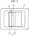
- FIG. 3 is a plan view illustrating the appearance of the printer 1 in an operation state.
- FIG. 4 is a vertical cross-sectional view of the printer 1 in a state corresponding to FIG. 1
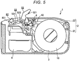
- FIG. 5 is a vertical cross-sectional view of the printer 1 in a state corresponding to FIG. 2
- FIG. 6 is a vertical cross-sectional view of the printer 1 in the operation state corresponding to FIG. 3 .
- the printer 1 includes a housing 2, a paper holding part 3, a printing part 4 and a peeling part 5, and performs printing on a roll paper 10.
- the roll paper 10 is formed by winding paper in which a label including a paste layer on a rear surface of a printed surface is adhered to a band-shaped pasteboard.
- the housing 2 includes a main body 21 and a cover 22 and includes the paper holding part 3, the printing part 4, the peeling part 5 and a battery 9 formed therein.
- the battery 9 is a secondary battery (rechargeable battery) and supplies power for operating the printer 1.
- the main body 21 is, for example, a box type container including an opening.
- One end (rotation-side end) of the cover 22 is rotatably supported by the main body 21 and is moved between a position where the opening of the main body 21 is closed (closed position, see FIG. 6 ) and a position where the opening of the main body 21 is opened (opened position, see FIG. 4 ), according to rotation.
- the paper holding part 3 is provided in the main body 21 and is opened and closed by the cover 22. In addition, the paper holding part 3 holds the roll paper 10 such that paper is drawn out.
- the printing part 4 is provided at a position in the main body 21 contacting with the other end of the cover 22 (that is, a movement-side end which is an end located at the opposite side of the rotation-side end) and performs printing on the paper drawn out from the paper holding part 3.
- the printing part 4 includes a printing head 41 (see FIGS. 6 to 8 ) and a platen 42.
- the printing head 41 is provided in the main body 21.
- the platen 42 is attached to the cover 22. In a state in which the cover 22 is closed, the platen 42 is brought into contact with the printing head 41 and the printing part 4 may perform printing.
- the printing head 41 is, for example, a thermal head, and performs printing on the printed surface of the label, by heating and coloring a thermosensitive color developable layer provided in the printed surface of the label.
- the platen 42 is a roller, which draws paper sandwiched between the printing head 41 and the platen from the paper holding part 3 by rotation and transports the paper.
- the peeling part 5 is disposed on a paper discharging port 23 to peel off the label from the pasteboard.
- the paper discharging port 23 is an opening for discharging printed paper with a gap formed between the movement-side end of the cover 22 at a closed position and the main body 21.
- the peeling part 5 includes a peeling bar 51, a pressing part 52 and a supporting part 53.
- the peeling bar 51 is located along the width direction of the pasteboard at the downstream side in the paper conveyance direction of the printing part 4.
- the peeling bar 51 is, for example, a member formed by bending a rectangular plate member such that a short side thereof has a mounting shape.
- the peeling bar 51 is disposed such that the ridge of the mountain shape faces the paper discharging port 23 and is parallel to the axial direction of the platen 42 and is provided on the movement-side end of the cover 22.
- the pressing part 52 is movable between a peeling position (see FIG. 6 ) and a retraction position (see FIG. 5 ) by supporting a base portion thereof by the supporting part 53 or is guided by the supporting part 53 to be movable between the peeling portion and a continuous position (not illustrated).
- the continuous position is a position of the pressing part 52 when the paper is discharged without peeling off the label from the pasteboard.
- the pressing part 52 at the peeling position illustrated in FIG. 6 presses the conveyed paper to be bent along the outer circumferential surface of the peeling bar 51 to peel off the label from the pasteboard.
- the pressing part 52 includes a peeling roller 521 at a front end portion thereof. Paper is sandwiched between the peeling roller 521 and the platen 42 in a state in which the pressing part 52 is located at the peeling position.
- the supporting part 53 supports and guides the pressing part 52 such that the pressing part is movable between the peeling position and the retraction position or between the peeling position and the continuous position.
- the supporting part 53 is a member including a fitting groove 531, into which a protrusion 522 provided at the base of the pressing part 52 is fitted, and the longitudinal direction of the groove 531 extends along the movement direction of the pressing part 52.
- the cross-sectional shape of the protrusion 522 is not circular but has a shape close to an ellipse, and has a thickness varying according to a direction.
- a portion of the groove 53, in which the protrusion 522 of the pressing part 52 at the peeling position is located, is widely formed such that the protrusion 522 is rotatable and the other portion of the groove 53 is narrowly formed such that the protrusion 522 is slidably guided in a certain direction.
- the pressing part 52 at the peeling position protrudes from the main body 21 to cover the peeling bar 51 and to press the paper against the peeling bar 51.
- the pressing part 52 at the retraction position is separated from the cover 22 not to interfere with rotation of the cover 22. That is, when the pressing part 52 is at the retraction position, the cover 22 may move to the opened position (see FIG. 4 ). Therefore, at least the base of the pressing part 52 at the continuous position is accommodated in the main body 21 such that the front end of the pressing part does not protrude from the paper discharging port 23 and does not interfere with the peeling bar 51.
- the pressing part 52 is biased by a bias member such as a spring in a direction separated from the main body 21.
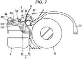
- FIG. 7 is a vertical cross-sectional view of the printer 1 illustrating a paper conveyance path.
- the paper drawn out from the roll paper 10 held by the paper holding part 3 is subjected to printing by the printing part 4 and is discharged from the paper discharging part 23. If the pressing part 52 is at the peeling position, the pasteboard is conveyed in a path denoted by a dotted line A and the label is peeled off from the pasteboard and moved in a path denoted by a solid line B.
- FIG. 8 is a vertical cross-sectional view of the printer 1 at the time of a lock releasing operation.
- the printer 1 further includes a pair of first lock parts 6, a pair of second lock parts 7 (see FIGS. 11 to 13 , described below) and an interlocking lock releasing part 8.
- the first lock parts 6 and the second lock parts 7 are disposed in the vicinities of both ends of the platen 42 inside the housing 2.
- the first lock parts 6 hold the cover 22 at a closed position.
- the second lock parts 7 fix the pressing part 52 at the peeling position with respect to the cover 22.
- the interlocking lock releasing part 8 releases position fixing by the second lock parts 7 using operation of a user as a power source and then releases holding by the first lock parts 6 subsequent to the releasing.
- FIG. 9 is a side view illustrating the appearance of the first lock part 6 and a releasing lever 81.
- the interlocking lock releasing part 8 includes a pair of releasing levers 81 and a releasing button 82.
- the releasing lever 81 is an example of a releasing member.
- the releasing button 82 is a button which rotates around a supporting point 821.
- the releasing button 82 is partially exposed to the outside of the housing 2 to receive pressing operation from the user and to deliver pressing to the pair of releasing levers 81.
- the releasing button 82 is biased by the biasing member such as the spring in a counterclockwise direction of FIG. 8 and is returned to the state illustrated in FIG. 8 if pressing operation by the user is not performed.
- the releasing lever 81 may rotate around the supporting point 811 and is biased by the bias member such as the spring in a clockwise direction of FIG. 8 .
- the first lock parts 6 are integrated with the releasing levers 81.
- the releasing lever 81 has a protruding end 812 disposed at a position where pressing operation applied to the releasing button 82 is received.
- the cover 22 is biased by the bias member such as the spring in a direction separated from the main body 21.
- the first lock part 6 is a recess which grips the end of the shaft 421 of the platen 42.
- the recess and the shaft 421 are engaged with each other such that the platen 42 is positioned with respect to the main body 21. Therefore, the cover 22 attached with the platen 42 is positioned with respect to the main body 21 to hold the cover 22 at the closed position.
- FIG. 10 is a side view illustrating releasing operation of the first lock part 6 by the releasing lever 81. If the user presses the releasing button 82, this operation (arrow C) is delivered to the protruding end 812 such that the releasing lever 81 rotates around the supporting point 811 in a counterclockwise direction (arrow D). Since the first lock part 6 is integrated with the releasing lever 81, gripping of the shaft 421 is released according to rotation of the releasing lever 81. The shaft 421 released from the first lock part 6 is moved in a direction, in which the cover 22 is opened, by biasing by the bias member (arrow E).
- a guide 61 is provided at a position closer to the cover 22 than the first lock parts 6.
- the guide 61 guides the shaft 421 of the platen 42 to the first lock part 6 and is realized by an inclined surface provided on the outer circumferential surface of the releasing lever 81 in the embodiment.
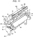
- FIG. 11 is a perspective view illustrating the structure of the second lock part 7
- FIG. 12 is a perspective view illustrating a holding state by the second lock part 7.
- the second lock parts 7 are disposed in the vicinities of both ends of the platen 42 inside the housing 2 and have a convex portion 71.
- the pressing part 52 includes a concave portion 72, into which the convex portion 71 is fitted.
- the second lock part 7 may rotate around a rotation shaft 73 and is biased by a bias member such as a spring in a direction in which the side end of the pressing part 52 is pressed.
- FIG. 13 is a perspective view illustrating releasing operation of the second lock part 7 by the releasing lever 81.
- the releasing lever 81 includes a protruding end 813 in the vicinity of a position where the second lock part 7 and the pressing part 52 are in pressure contact with each other.
- the protruding end 813 interferes with the second lock part 7 when the releasing lever 81 moves in a direction denoted by arrow D, and rotates the second lock part 7 against biasing force in a direction denoted by arrow F. Therefore, lock by the second lock parts 7 is released such that the pressing part 52 is separable from the platen 42.
- the second lock part 7 includes a guide 74 and the pressing part 52 includes a guided part 75.
- the guide 74 is an inclined surface near the pressing part 52 in a direction in which the pressing part 52 moves from the retraction position to the peeling direction.
- the guided part 75 slides to the guide part 74 and the second lock part 7 rotates in a direction denoted by arrow F (see FIG. 13 ) .
- the convex portion 71 is fitted into the concave portion 72, the pressing part 52 is fixed at the peeling position.
- the interlocking lock releasing part 8 releases both lock (holding) by the first lock part 6 and lock (position fixing) by the second lock part 7 using operation of the user as a power source, two lock releasing operations are not simultaneously performed, and the shape of the releasing lever 81 is adjusted such that position fixing by the second lock part 7 is first released and then holding by the first lock part 6 is released. That is, the position of the protruding end 813 with respect to the supporting point 811 and the position of the portion switched from the guide 61 to the first lock part 6 are adjusted.
- the releasing lever 81 has a shape for realizing a structure for shifting two lock timings and sequentially performing releasing, that is, a structure in which the first lock part 6 releases gripping of the shaft 421 when the releasing lever 81 further rotates after the protruding end 813 rotates the second lock part 7.
- the interlocking lock releasing part 8 performs releasing of holding by the first lock part 6 and releasing of position fixing by the second lock part 7 at two positions where angles of rotation around the supporting point 811 are different from each other.
- the printer 1 receives one operation of pressing the releasing button 82 by the user and opens the housing 2.
- the printer 1 of the embodiment even if operations of the pressing part 52 and the cover 22 when opening the housing 2 are interlocked to open the housing 2 through one action, the movement timing of the pressing part 52 and the movement timing of the cover 22 are shifted.
- the cover 22 moves to the closed position and then the pressing part 52 moves to the peeling position to be covered by the cover 22. Therefore, it is possible to avoid interference between the member configuring the pressing part 52 and the member attached to the cover 22. Since the degree of freedom of the shape or size of the peeling bar 51 increases, it is possible to configure the printer 1 having excellent peeling performance.
- the shape or size of the peeling bar located in the vicinity of the platen attached to the cover is restricted such that interference with the peeling roller provided in the pressing part is not caused and thus peeling performance is also restricted.
- the peeling bar preferably has a shape which allows a pasteboard to be bent at an acute angle, it is difficult for the printer of the related art to perform the above-described operation.
- the printer 1 of the embodiment even if operations of the pressing part 52 and the cover 22 when opening the housing 2 are interlocked, operation timings are shifted, thereby avoiding interference therebetween and the pressing part and the cover are separately closed when the housing 2 is closed. Therefore, the size or shape of the member such as the peeling bar 51 is not restricted, and the peeling bar 51 having a shape which allows the pasteboard to be bent at an acute angle is easily installed, thereby improving peeling performance.
- first lock part 6 and the interlocking lock releasing part 8 are integrally provided (the first lock part 6 is integrated with the releasing lever 81) in the above-described embodiment, the embodiments are not limited thereto and any structure for realizing interlocking in which timings are shifted may be used.
Landscapes
- Accessory Devices And Overall Control Thereof (AREA)
- Printers Characterized By Their Purpose (AREA)
- Handling Of Continuous Sheets Of Paper (AREA)
- Folding Of Thin Sheet-Like Materials, Special Discharging Devices, And Others (AREA)
Abstract
A cover (22) includes one end rotatably supported by a main body (21). A paper holding part (3) holds the roll paper (10), in which a label including a paste layer on a rear surface of a printable surface is adhered to a band-shaped pasteboard. A printing part is provided at a position in the main body contacting with the other end of the cover to perform printing on paper. A peeling bar (51) is provided in the other end of the cover and is located in a width direction of the pasteboard at a downstream of a paper conveyance direction of the printing part. A pressing part (52) presses the conveyed paper to bend the paper and peels off the label from the pasteboard. A first lock part (6) holds the cover at the closed position. A second lock part fixes the pressing part with respect to the cover. An interlocking lock releasing part releases position fixing by the second lock part and releases holding by the first lock part subsequent to the releasing.
Description
- This application is based upon and claims the benefit of priority from Japanese Patent Application No.
P2018-021331, filed on February 8, 2018 - Embodiments described herein relate generally to a printer.
- In the related art, there is a portable printer which may be carried and used. Such a printer is equipped with a paper holding part in a housing. The housing includes a main body provided with an opening and a cover for opening and closing the opening, and the cover is opened at the time of other maintenance such as when paper is refilled or replaced.
- In the above-described printer, a label adhered to a pasteboard may be peeled off and issued. In such a printer, when the label is peeled off, the pasteboard is bent and conveyed in the conveyance direction of the label.
- The printer includes a peeling bar and a pressing part as a configuration for bending the pasteboard. The pressing part presses the pasteboard against the peeling bar, such that a front side (a side to which the label is adhered) of the pasteboard is bent in a mountain fold and a rear side of the pasteboard is bent in a valley fold.
- In the printer of the related art, the housing is opened and closed by one operation of a user in order to improve operability. Such a printer is configured such that opening and closing of the cover and operation of the pressing part are interlocked with each other.
- In the configuration in which the cover and the pressing part are interlocked with each other, the sizes or shapes of the members may be restricted such that a member attached to the cover and a member configuring the pressing part do not collide with each other when the housing is opened and closed. In particular, if the size or shape of the peeling bar is restricted, peeling performance is restricted.
- One of the objects of the present invention is to improve prior art techniques and overcome at least some of the prior art problems as for instance above illustrated.
- According to a first aspect of the present invention, it is provided a printer for printing on roll paper in which a label including a paste layer on a rear surface of a printed surface is adhered to a band-shaped pasteboard, the printer comprising: a main body having an opening; a cover including one end rotatably supported by the main body and moving from a closed position where the opening of the main body is closed to an opened position where the opening of the main body is opened, according to rotation; a paper holding part configured to hold the roll paper in the main body and to be opened and closed by the cover; a printing part provided at a position in the main body contacting with the other end of the cover to print on the paper drawn out from the paper holding part; a peeling bar provided at the other end of the cover and located in a width direction of the pasteboard at a downstream of a paper conveyance direction of the printing part; a pressing part configured to press the conveyed paper to bend the paper along an outer circumferential surface of the peeling bar and to peel off the label from the pasteboard; a first lock part configured to hold the cover at the closed position; a second lock part configured to fix the pressing part with respect to the cover; and an interlocking lock releasing part configured to release position fixing by the second lock part and to release holding by the first lock part subsequent to the releasing.
- Optionally, in the printer according to the first aspect of the invention, the interlocking lock releasing part includes a releasing member that is rotatable around a predetermined supporting point and releases holding by the first lock part and position fixing by the second lock part at positions where rotation angles are different from each other.
- Optionally, in the printer according to the first aspect of the invention, the printing part comprises a printing head provided in the main body and a platen attached to the cover and brought into contact with the printing head when the cover is at the closed position, and the peeling bar is attached to the cover to face a paper discharging port formed between the cover at the closed position and the main body.
- Optionally, in the printer according to the first aspect of the invention, the interlocking lock releasing part includes a releasing button configured to receive operation of a user from the outside of the main body.
- Optionally, in the printer according to the first aspect of the invention, the pressing part is movable to a continuous position which does not interfere with the peeling bar for discharging the paper without peeling off the label from the pasteboard.
- Optionally, in the printer according to the first aspect of the invention, the platen comprises a roller.
- Optionally, in the printer according to the first aspect of the invention, the printing part comprises a thermal head.
- According to a second aspect of the invention, a portable printer for printing on a label adhered to roll paper, the portable printer comprising: a main body having an opening; a cover including one end rotatably supported by the main body and moving from a closed position where the opening of the main body is closed to an opened position where the opening of the main body is opened, according to rotation; a paper holding part configured to hold the roll paper in the main body and to be opened and closed by the cover; a printing part provided at a position in the main body contacting with the other end of the cover to print on the paper drawn out from the paper holding part; a peeling bar provided at the other end of the cover and located in a width direction of the roll paper at a downstream of a paper conveyance direction of the printing part; a pressing part configured to press the conveyed paper to bend the paper along an outer circumferential surface of the peeling bar and to peel off the label from the roll paper; a first lock part configured to hold the cover at the closed position; a second lock part configured to fix the pressing part with respect to the cover; and an interlocking lock releasing part configured to release position fixing by the second lock part and to release holding by the first lock part subsequent to the releasing.
- Optionally, in the portable printer according to the second aspect of the invention, the interlocking lock releasing part includes a releasing member that is rotatable around a predetermined supporting point and releases holding by the first lock part and position fixing by the second lock part at positions where rotation angles are different from each other.
- Optionally, in the portable printer according to the second aspect of the invention, the printing part comprises a printing head provided in the main body and a platen attached to the cover and brought into contact with the printing head when the cover is at the closed position, and the peeling bar is attached to the cover to face a paper discharging port formed between the cover at the closed position and the main body.
- Optionally, in the portable printer according to the second aspect of the invention, the interlocking lock releasing part includes a releasing button configured to receive operation of a user from the outside of the main body.
- Optionally, in the portable printer according to the second aspect of the invention, the pressing part is movable to a continuous position which does not interfere with the peeling bar for discharging the paper without peeling off the label from the roll paper.
- Optionally, in the portable printer according to the second aspect of the invention, the platen comprises a roller.
- Optionally, in the portable printer according to the second aspect of the invention, the printing part comprises a thermal head.
- According to a third aspect of the invention, a label printer for printing on a label adhered to roll paper, the label printer comprising: a main body having an opening; a cover including one end rotatably supported by the main body and moving from a closed position where the opening of the main body is closed to an opened position where the opening of the main body is opened, according to rotation; a paper holding part configured to hold the roll paper in the main body and to be opened and closed by the cover; a printing part provided at a position in the main body contacting with the other end of the cover to print on the paper drawn out from the paper holding part; a peeling bar provided at the other end of the cover and located in a width direction of the roll paper at a downstream of a paper conveyance direction of the printing part; a pressing part configured to press the conveyed paper to bend the paper along an outer circumferential surface of the peeling bar and to peel off the label from the roll paper; a first lock part configured to hold the cover at the closed position; a second lock part configured to fix the pressing part with respect to the cover; and an interlocking lock releasing part configured to release position fixing by the second lock part and to release holding by the first lock part subsequent to the releasing.
- Optionally, in the label printer according to the third aspect of the invention, the interlocking lock releasing part includes a releasing member that is rotatable around a predetermined supporting point and releases holding by the first lock part and position fixing by the second lock part at positions where rotation angles are different from each other.
- Optionally, in the label printer according to the third aspect of the invention, the printing part comprises a printing head provided in the main body and a platen attached to the cover and brought into contact with the printing head when the cover is at the closed position, and the peeling bar is attached to the cover to face a paper discharging port formed between the cover at the closed position and the main body.
- Optionally, in the label printer according to the third aspect of the invention, the interlocking lock releasing part includes a releasing button configured to receive operation of a user from the outside of the main body.
- Optionally, in the label printer according to the third aspect of the invention, the pressing part is movable to a continuous position which does not interfere with the peeling bar for discharging the paper without peeling off the label from the roll paper.
- Optionally, in the label printer according to the third aspect of the invention, the printing part comprises a thermal head.
-
-
FIG. 1 is a perspective view illustrating the appearance of a printer according to an embodiment when a cover is opened; -
FIG. 2 is a perspective view illustrating the appearance of the printer when the cover is closed; -
FIG. 3 is a plan view illustrating the appearance of the printer in an operation state; -
FIG. 4 is a vertical cross-sectional view of the printer in a state corresponding toFIG. 1 ; -
FIG. 5 is a vertical cross-sectional view of the printer in a state corresponding toFIG. 2 ; -
FIG. 6 is a vertical cross-sectional view of the printer in the operation state corresponding toFIG. 3 ; -
FIG. 7 is a vertical cross-sectional view of the printer illustrating a paper conveyance path; -
FIG. 8 is a vertical cross-sectional view of the printer at the time of a lock releasing operation; -
FIG. 9 is a side view illustrating the appearance of a first lock part and a releasing lever; -
FIG. 10 is a side view illustrating releasing operation of the first lock part by the releasing lever; -
FIG. 11 is a perspective view illustrating the structure of a second lock part; -
FIG. 12 is a perspective view illustrating a holding state by the second lock part; and -
FIG. 13 is a perspective view illustrating releasing operation of the second lock part by the releasing lever. - An exemplary embodiment provides a printer having good balance between operability at the time of opening and closing a housing and label peeling performance.
- In general, according to one embodiment, a printer for performing printing on roll paper formed by winding paper in which a label including a paste layer on a rear surface of a printed surface is adhered to a band-shaped pasteboard includes a main body as a container provided with an opening, a cover including one end rotatably supported by the main body and moving from a closed position where the opening of the main body is closed to an opened position where the opening is opened, according to rotation, a paper holding part configured to hold the roll paper in the main body and to be opened and closed by the cover, a printing part provided at a position in the main body contacting with the other end of the cover to perform printing on the paper drawn out from the paper holding part, a peeling bar provided in the other end of the cover and located in a width direction of the pasteboard at a downstream of a paper conveyance direction of the printing part, a pressing part configured to press the conveyed paper to bend the paper along an outer circumferential surface of the peeling bar and to peel off the label from the pasteboard, a first lock part configured to hold the cover at the closed position, a second lock part configured to fix the pressing part with respect to the cover, and an interlocking lock releasing part configured to release position fixing by the second lock part and to release holding by the first lock part subsequent to the releasing.
- An embodiment will be described with reference to the drawings.
FIG. 1 is a perspective view illustrating the appearance of aprinter 1 when acover 22 is opened,FIG. 2 is a perspective view illustrating the appearance of theprinter 1 when thecover 22 is closed, andFIG. 3 is a plan view illustrating the appearance of theprinter 1 in an operation state. -
FIG. 4 is a vertical cross-sectional view of theprinter 1 in a state corresponding toFIG. 1 ,FIG. 5 is a vertical cross-sectional view of theprinter 1 in a state corresponding toFIG. 2 , andFIG. 6 is a vertical cross-sectional view of theprinter 1 in the operation state corresponding toFIG. 3 . - The
printer 1 includes ahousing 2, apaper holding part 3, aprinting part 4 and apeeling part 5, and performs printing on aroll paper 10. Theroll paper 10 is formed by winding paper in which a label including a paste layer on a rear surface of a printed surface is adhered to a band-shaped pasteboard. Thehousing 2 includes amain body 21 and acover 22 and includes thepaper holding part 3, theprinting part 4, thepeeling part 5 and abattery 9 formed therein. Thebattery 9 is a secondary battery (rechargeable battery) and supplies power for operating theprinter 1. - The
main body 21 is, for example, a box type container including an opening. One end (rotation-side end) of thecover 22 is rotatably supported by themain body 21 and is moved between a position where the opening of themain body 21 is closed (closed position, seeFIG. 6 ) and a position where the opening of themain body 21 is opened (opened position, seeFIG. 4 ), according to rotation. - The
paper holding part 3 is provided in themain body 21 and is opened and closed by thecover 22. In addition, thepaper holding part 3 holds theroll paper 10 such that paper is drawn out. - The
printing part 4 is provided at a position in themain body 21 contacting with the other end of the cover 22 (that is, a movement-side end which is an end located at the opposite side of the rotation-side end) and performs printing on the paper drawn out from thepaper holding part 3. Theprinting part 4 includes a printing head 41 (seeFIGS. 6 to 8 ) and aplaten 42. - The
printing head 41 is provided in themain body 21. Theplaten 42 is attached to thecover 22. In a state in which thecover 22 is closed, theplaten 42 is brought into contact with theprinting head 41 and theprinting part 4 may perform printing. - The
printing head 41 is, for example, a thermal head, and performs printing on the printed surface of the label, by heating and coloring a thermosensitive color developable layer provided in the printed surface of the label. Theplaten 42 is a roller, which draws paper sandwiched between theprinting head 41 and the platen from thepaper holding part 3 by rotation and transports the paper. - The peeling
part 5 is disposed on apaper discharging port 23 to peel off the label from the pasteboard. Thepaper discharging port 23 is an opening for discharging printed paper with a gap formed between the movement-side end of thecover 22 at a closed position and themain body 21. - The peeling
part 5 includes a peelingbar 51, apressing part 52 and a supportingpart 53. The peelingbar 51 is located along the width direction of the pasteboard at the downstream side in the paper conveyance direction of theprinting part 4. The peelingbar 51 is, for example, a member formed by bending a rectangular plate member such that a short side thereof has a mounting shape. The peelingbar 51 is disposed such that the ridge of the mountain shape faces thepaper discharging port 23 and is parallel to the axial direction of theplaten 42 and is provided on the movement-side end of thecover 22. - The
pressing part 52 is movable between a peeling position (seeFIG. 6 ) and a retraction position (seeFIG. 5 ) by supporting a base portion thereof by the supportingpart 53 or is guided by the supportingpart 53 to be movable between the peeling portion and a continuous position (not illustrated). Here, the continuous position is a position of thepressing part 52 when the paper is discharged without peeling off the label from the pasteboard. - The
pressing part 52 at the peeling position illustrated inFIG. 6 presses the conveyed paper to be bent along the outer circumferential surface of the peelingbar 51 to peel off the label from the pasteboard. Thepressing part 52 includes a peelingroller 521 at a front end portion thereof. Paper is sandwiched between the peelingroller 521 and theplaten 42 in a state in which thepressing part 52 is located at the peeling position. - The supporting
part 53 supports and guides thepressing part 52 such that the pressing part is movable between the peeling position and the retraction position or between the peeling position and the continuous position. Specifically, the supportingpart 53 is a member including afitting groove 531, into which aprotrusion 522 provided at the base of thepressing part 52 is fitted, and the longitudinal direction of thegroove 531 extends along the movement direction of thepressing part 52. - The cross-sectional shape of the
protrusion 522 is not circular but has a shape close to an ellipse, and has a thickness varying according to a direction. A portion of thegroove 53, in which theprotrusion 522 of thepressing part 52 at the peeling position is located, is widely formed such that theprotrusion 522 is rotatable and the other portion of thegroove 53 is narrowly formed such that theprotrusion 522 is slidably guided in a certain direction. - The
pressing part 52 at the peeling position protrudes from themain body 21 to cover the peelingbar 51 and to press the paper against the peelingbar 51. In addition, thepressing part 52 at the retraction position is separated from thecover 22 not to interfere with rotation of thecover 22. That is, when thepressing part 52 is at the retraction position, thecover 22 may move to the opened position (seeFIG. 4 ). Therefore, at least the base of thepressing part 52 at the continuous position is accommodated in themain body 21 such that the front end of the pressing part does not protrude from thepaper discharging port 23 and does not interfere with the peelingbar 51. - In addition, the
pressing part 52 is biased by a bias member such as a spring in a direction separated from themain body 21. -
FIG. 7 is a vertical cross-sectional view of theprinter 1 illustrating a paper conveyance path. In such aprinter 1, the paper drawn out from theroll paper 10 held by thepaper holding part 3 is subjected to printing by theprinting part 4 and is discharged from thepaper discharging part 23. If thepressing part 52 is at the peeling position, the pasteboard is conveyed in a path denoted by a dotted line A and the label is peeled off from the pasteboard and moved in a path denoted by a solid line B. -
FIG. 8 is a vertical cross-sectional view of theprinter 1 at the time of a lock releasing operation. Theprinter 1 further includes a pair offirst lock parts 6, a pair of second lock parts 7 (seeFIGS. 11 to 13 , described below) and an interlocking lock releasing part 8. Thefirst lock parts 6 and thesecond lock parts 7 are disposed in the vicinities of both ends of theplaten 42 inside thehousing 2. - The
first lock parts 6 hold thecover 22 at a closed position. Thesecond lock parts 7 fix thepressing part 52 at the peeling position with respect to thecover 22. The interlocking lock releasing part 8 releases position fixing by thesecond lock parts 7 using operation of a user as a power source and then releases holding by thefirst lock parts 6 subsequent to the releasing. -
FIG. 9 is a side view illustrating the appearance of thefirst lock part 6 and a releasinglever 81. The interlocking lock releasing part 8 includes a pair of releasinglevers 81 and a releasingbutton 82. The releasinglever 81 is an example of a releasing member. - The releasing
button 82 is a button which rotates around a supportingpoint 821. The releasingbutton 82 is partially exposed to the outside of thehousing 2 to receive pressing operation from the user and to deliver pressing to the pair of releasinglevers 81. The releasingbutton 82 is biased by the biasing member such as the spring in a counterclockwise direction ofFIG. 8 and is returned to the state illustrated inFIG. 8 if pressing operation by the user is not performed. - The releasing
lever 81 may rotate around the supportingpoint 811 and is biased by the bias member such as the spring in a clockwise direction ofFIG. 8 . Thefirst lock parts 6 are integrated with the releasinglevers 81. In addition, the releasinglever 81 has aprotruding end 812 disposed at a position where pressing operation applied to the releasingbutton 82 is received. - In addition, the
cover 22 is biased by the bias member such as the spring in a direction separated from themain body 21. - The
first lock part 6 is a recess which grips the end of theshaft 421 of theplaten 42. The recess and theshaft 421 are engaged with each other such that theplaten 42 is positioned with respect to themain body 21. Therefore, thecover 22 attached with theplaten 42 is positioned with respect to themain body 21 to hold thecover 22 at the closed position. -
FIG. 10 is a side view illustrating releasing operation of thefirst lock part 6 by the releasinglever 81. If the user presses the releasingbutton 82, this operation (arrow C) is delivered to theprotruding end 812 such that the releasinglever 81 rotates around the supportingpoint 811 in a counterclockwise direction (arrow D). Since thefirst lock part 6 is integrated with the releasinglever 81, gripping of theshaft 421 is released according to rotation of the releasinglever 81. Theshaft 421 released from thefirst lock part 6 is moved in a direction, in which thecover 22 is opened, by biasing by the bias member (arrow E). - Here, a
guide 61 is provided at a position closer to thecover 22 than thefirst lock parts 6. Theguide 61 guides theshaft 421 of theplaten 42 to thefirst lock part 6 and is realized by an inclined surface provided on the outer circumferential surface of the releasinglever 81 in the embodiment. - When the
cover 22 is closed, the outer circumferential surface of theshaft 421 moved together with thecover 22 slides to theguide 61 to rotate the releasinglever 81 in the counterclockwise direction. Theshaft 421 is guided to thefirst lock part 6 by theguide 61. If theshaft 421 is fitted into thefirst lock part 6, the releasinglever 81 rotates in the clockwise direction and returns to the position illustrated inFIG. 9 . -
FIG. 11 is a perspective view illustrating the structure of thesecond lock part 7, andFIG. 12 is a perspective view illustrating a holding state by thesecond lock part 7. Thesecond lock parts 7 are disposed in the vicinities of both ends of theplaten 42 inside thehousing 2 and have aconvex portion 71. Thepressing part 52 includes aconcave portion 72, into which theconvex portion 71 is fitted. Thesecond lock part 7 may rotate around arotation shaft 73 and is biased by a bias member such as a spring in a direction in which the side end of thepressing part 52 is pressed. -
FIG. 13 is a perspective view illustrating releasing operation of thesecond lock part 7 by the releasinglever 81. The releasinglever 81 includes aprotruding end 813 in the vicinity of a position where thesecond lock part 7 and thepressing part 52 are in pressure contact with each other. Theprotruding end 813 interferes with thesecond lock part 7 when the releasinglever 81 moves in a direction denoted by arrow D, and rotates thesecond lock part 7 against biasing force in a direction denoted by arrow F. Therefore, lock by thesecond lock parts 7 is released such that thepressing part 52 is separable from theplaten 42. - As illustrated in
FIGS. 11 and12 , thesecond lock part 7 includes aguide 74 and thepressing part 52 includes a guidedpart 75. Theguide 74 is an inclined surface near thepressing part 52 in a direction in which thepressing part 52 moves from the retraction position to the peeling direction. When thepressing part 52 moves from the retraction position to the peeling position, the guidedpart 75 slides to theguide part 74 and thesecond lock part 7 rotates in a direction denoted by arrow F (seeFIG. 13 ) . When theconvex portion 71 is fitted into theconcave portion 72, thepressing part 52 is fixed at the peeling position. - Although the interlocking lock releasing part 8 releases both lock (holding) by the
first lock part 6 and lock (position fixing) by thesecond lock part 7 using operation of the user as a power source, two lock releasing operations are not simultaneously performed, and the shape of the releasinglever 81 is adjusted such that position fixing by thesecond lock part 7 is first released and then holding by thefirst lock part 6 is released. That is, the position of theprotruding end 813 with respect to the supportingpoint 811 and the position of the portion switched from theguide 61 to thefirst lock part 6 are adjusted. - More specifically, the releasing
lever 81 has a shape for realizing a structure for shifting two lock timings and sequentially performing releasing, that is, a structure in which thefirst lock part 6 releases gripping of theshaft 421 when the releasinglever 81 further rotates after theprotruding end 813 rotates thesecond lock part 7. - By such a structure, the interlocking lock releasing part 8 performs releasing of holding by the
first lock part 6 and releasing of position fixing by thesecond lock part 7 at two positions where angles of rotation around the supportingpoint 811 are different from each other. - Next, operation of opening the
housing 2 of theprinter 1 will be described. If the releasingbutton 82 is pressed, pressing force is delivered to theprotruding end 812 such that the releasinglever 81 rotates around the supportingpart 811. - According to rotation of the releasing
lever 81, first, lock by thesecond lock part 7 is released such that thepressing part 52 rotates by biasing of the bias member in a direction separated from theplaten 42. - When the releasing
lever 81 further rotates, lock by thefirst lock part 6 is released subsequent to releasing of lock by thesecond lock parts 7 such that thecover 22 rotates by biasing of the bias member in a direction separated from themain body 21. - As described above, the
printer 1 receives one operation of pressing the releasingbutton 82 by the user and opens thehousing 2. - Next, operation when the
housing 2 of theprinter 1 is closed will be described. When thecover 22 moves from the opened position to the closed position, theshaft 421 of theplaten 42 is guided to theguide 61 to be fitted into thefirst lock part 6, thereby maintaining thecover 22 at the closed position. - Subsequently, when the
pressing part 52 moves from the retraction position to the peeling position, theconvex portion 71 of thesecond lock part 7 is fitted into theconcave portion 72 of thepressing part 52, such that thepressing part 52 is fixed with respect to thecover 22. - As described above, in the
printer 1 of the embodiment, even if operations of thepressing part 52 and thecover 22 when opening thehousing 2 are interlocked to open thehousing 2 through one action, the movement timing of thepressing part 52 and the movement timing of thecover 22 are shifted. In addition, in theprinter 1 of the embodiment, when thehousing 2 is closed, thecover 22 moves to the closed position and then thepressing part 52 moves to the peeling position to be covered by thecover 22. Therefore, it is possible to avoid interference between the member configuring thepressing part 52 and the member attached to thecover 22. Since the degree of freedom of the shape or size of the peelingbar 51 increases, it is possible to configure theprinter 1 having excellent peeling performance. - In the printer of the related art, in interlocking movement of the pressing part with opening and closing of the cover, the shape or size of the peeling bar located in the vicinity of the platen attached to the cover is restricted such that interference with the peeling roller provided in the pressing part is not caused and thus peeling performance is also restricted. Although the peeling bar preferably has a shape which allows a pasteboard to be bent at an acute angle, it is difficult for the printer of the related art to perform the above-described operation.
- In contrast, in the
printer 1 of the embodiment, even if operations of thepressing part 52 and thecover 22 when opening thehousing 2 are interlocked, operation timings are shifted, thereby avoiding interference therebetween and the pressing part and the cover are separately closed when thehousing 2 is closed. Therefore, the size or shape of the member such as the peelingbar 51 is not restricted, and the peelingbar 51 having a shape which allows the pasteboard to be bent at an acute angle is easily installed, thereby improving peeling performance. - Although the
first lock part 6 and the interlocking lock releasing part 8 are integrally provided (thefirst lock part 6 is integrated with the releasing lever 81) in the above-described embodiment, the embodiments are not limited thereto and any structure for realizing interlocking in which timings are shifted may be used. - While certain embodiments have been described, these embodiments have been presented by way of example only, and are not intended to limit the scope of the inventions. Indeed, the novel embodiments described herein may be embodied in a variety of other forms; furthermore, various omissions, substitutions and changes in the form of the embodiments described herein may be made without departing from the scope of the inventions. The accompanying claims and their equivalents are intended to cover such forms or modifications as would fall within the scope of the inventions.
Claims (15)
- A printer for printing on roll paper in which a label including a paste layer on a rear surface of a printed surface is adhered to a band-shaped pasteboard, the printer comprising:a main body having an opening;a cover including one end rotatably supported by the main body and moving from a closed position where the opening of the main body is closed to an opened position where the opening of the main body is opened, according to rotation;a paper holding part configured to hold the roll paper in the main body and to be opened and closed by the cover;a printing part provided at a position in the main body contacting with the other end of the cover to print on the paper drawn out from the paper holding part;a peeling bar provided at the other end of the cover and located in a width direction of the pasteboard at a downstream of a paper conveyance direction of the printing part;a pressing part configured to press the conveyed paper to bend the paper along an outer circumferential surface of the peeling bar and to peel off the label from the pasteboard;a first lock part configured to hold the cover at the closed position;a second lock part configured to fix the pressing part with respect to the cover; andan interlocking lock releasing part configured to release position fixing by the second lock part and to release holding by the first lock part subsequent to the releasing.
- The printer according to claim 1, wherein
the interlocking lock releasing part includes a releasing member that is rotatable around a predetermined supporting point and releases holding by the first lock part and position fixing by the second lock part at positions where rotation angles are different from each other. - The printer according to claim 1 or 2, wherein
the printing part comprises a printing head provided in the main body and a platen attached to the cover and brought into contact with the printing head when the cover is at the closed position, and
the peeling bar is attached to the cover to face a paper discharging port formed between the cover at the closed position and the main body. - The printer according to any of claims 1 to 3, wherein
the interlocking lock releasing part includes a releasing button configured to receive operation of a user from the outside of the main body. - The printer according to any of claims 1 to 4, wherein
the pressing part is movable to a continuous position which does not interfere with the peeling bar for discharging the paper without peeling off the label from the pasteboard. - The printer according to claim 3, wherein
the platen comprises a roller. - The printer according to any of claims 1 to 6, wherein
the printing part comprises a thermal head. - A portable printer for printing on a label adhered to roll paper, the portable printer comprising:a main body having an opening;a cover including one end rotatably supported by the main body and moving from a closed position where the opening of the main body is closed to an opened position where the opening of the main body is opened, according to rotation;a paper holding part configured to hold the roll paper in the main body and to be opened and closed by the cover;a printing part provided at a position in the main body contacting with the other end of the cover to print on the paper drawn out from the paper holding part;a peeling bar provided at the other end of the cover and located in a width direction of the roll paper at a downstream of a paper conveyance direction of the printing part;a pressing part configured to press the conveyed paper to bend the paper along an outer circumferential surface of the peeling bar and to peel off the label from the roll paper;a first lock part configured to hold the cover at the closed position;a second lock part configured to fix the pressing part with respect to the cover; andan interlocking lock releasing part configured to release position fixing by the second lock part and to release holding by the first lock part subsequent to the releasing.
- The portable printer according to claim 8, wherein
the interlocking lock releasing part includes a releasing member that is rotatable around a predetermined supporting point and releases holding by the first lock part and position fixing by the second lock part at positions where rotation angles are different from each other. - The portable printer according to claim 8 or 9, wherein
the printing part comprises a printing head provided in the main body and a platen attached to the cover and brought into contact with the printing head when the cover is at the closed position, and
the peeling bar is attached to the cover to face a paper discharging port formed between the cover at the closed position and the main body. - The portable printer according to any of claims 8 to 10, wherein
the interlocking lock releasing part includes a releasing button configured to receive operation of a user from the outside of the main body. - The portable printer according to any of claims 8 to 11, wherein
the pressing part is movable to a continuous position which does not interfere with the peeling bar for discharging the paper without peeling off the label from the roll paper. - The portable printer according to claim 10, wherein
the platen comprises a roller. - The portable printer according to any of claims 8 to 13, wherein
the printing part comprises a thermal head. - A label printer for printing on a label adhered to roll paper, the label printer comprising:a main body having an opening;a cover including one end rotatably supported by the main body and moving from a closed position where the opening of the main body is closed to an opened position where the opening of the main body is opened, according to rotation;a paper holding part configured to hold the roll paper in the main body and to be opened and closed by the cover;a printing part provided at a position in the main body contacting with the other end of the cover to print on the paper drawn out from the paper holding part;a peeling bar provided at the other end of the cover and located in a width direction of the roll paper at a downstream of a paper conveyance direction of the printing part;a pressing part configured to press the conveyed paper to bend the paper along an outer circumferential surface of the peeling bar and to peel off the label from the roll paper;a first lock part configured to hold the cover at the closed position;a second lock part configured to fix the pressing part with respect to the cover; andan interlocking lock releasing part configured to release position fixing by the second lock part and to release holding by the first lock part subsequent to the releasing.
Applications Claiming Priority (1)
| Application Number | Priority Date | Filing Date | Title |
|---|---|---|---|
| JP2018021331A JP2019136919A (en) | 2018-02-08 | 2018-02-08 | Printer |
Publications (1)
| Publication Number | Publication Date |
|---|---|
| EP3524436A1 true EP3524436A1 (en) | 2019-08-14 |
Family
ID=65279446
Family Applications (1)
| Application Number | Title | Priority Date | Filing Date |
|---|---|---|---|
| EP19155267.8A Withdrawn EP3524436A1 (en) | 2018-02-08 | 2019-02-04 | Printer |
Country Status (4)
| Country | Link |
|---|---|
| US (1) | US20190240998A1 (en) |
| EP (1) | EP3524436A1 (en) |
| JP (1) | JP2019136919A (en) |
| CN (1) | CN110126486A (en) |
Families Citing this family (10)
| Publication number | Priority date | Publication date | Assignee | Title |
|---|---|---|---|---|
| CN111169178B (en) * | 2020-02-26 | 2025-05-09 | 江门市得实计算机外部设备有限公司 | A portable printer with internal and external paper feeding |
| JP7532928B2 (en) * | 2020-06-11 | 2024-08-14 | ブラザー工業株式会社 | Printing device |
| CN111845109B (en) * | 2020-07-08 | 2025-12-19 | 厦门汉印股份有限公司 | Portable printer with cover opening structure |
| JP7698248B2 (en) * | 2020-11-18 | 2025-06-25 | 株式会社サトー | Printer |
| JP7746014B2 (en) * | 2021-02-02 | 2025-09-30 | 東芝テック株式会社 | Paper storage device |
| JP7608228B2 (en) * | 2021-03-22 | 2025-01-06 | 東芝テック株式会社 | Label printer |
| JP7723509B2 (en) * | 2021-06-23 | 2025-08-14 | 東芝テック株式会社 | label printer |
| CN113571367B (en) * | 2021-08-04 | 2024-04-12 | 杭州恒汇智能装备有限公司 | Intelligent cloud box with multistage feedback keys |
| JP7435650B2 (en) * | 2022-03-24 | 2024-02-21 | カシオ計算機株式会社 | Holding mechanism and printing device |
| CN118061682B (en) * | 2024-03-28 | 2026-05-15 | 厦门汉印股份有限公司 | printer |
Citations (1)
| Publication number | Priority date | Publication date | Assignee | Title |
|---|---|---|---|---|
| US20100178094A1 (en) * | 2004-12-27 | 2010-07-15 | Seiko Epson Corporation | Printer with a peeler mechanism |
Family Cites Families (5)
| Publication number | Priority date | Publication date | Assignee | Title |
|---|---|---|---|---|
| DE60211596T2 (en) * | 2001-06-25 | 2006-12-21 | Seiko Epson Corp. | printer |
| US9434191B2 (en) * | 2010-04-12 | 2016-09-06 | Zih Corp. | Label peeling, universal printheads and related methods |
| WO2011130319A1 (en) * | 2010-04-12 | 2011-10-20 | Zih Corp. | Mobile printer networking and interfacing |
| JP5850977B2 (en) * | 2014-04-28 | 2016-02-03 | サトーホールディングス株式会社 | Printer |
| JP5844489B1 (en) * | 2015-01-29 | 2016-01-20 | サトーホールディングス株式会社 | Printer |
-
2018
- 2018-02-08 JP JP2018021331A patent/JP2019136919A/en active Pending
-
2019
- 2019-01-07 CN CN201910012520.7A patent/CN110126486A/en not_active Withdrawn
- 2019-01-10 US US16/244,168 patent/US20190240998A1/en not_active Abandoned
- 2019-02-04 EP EP19155267.8A patent/EP3524436A1/en not_active Withdrawn
Patent Citations (1)
| Publication number | Priority date | Publication date | Assignee | Title |
|---|---|---|---|---|
| US20100178094A1 (en) * | 2004-12-27 | 2010-07-15 | Seiko Epson Corporation | Printer with a peeler mechanism |
Also Published As
| Publication number | Publication date |
|---|---|
| JP2019136919A (en) | 2019-08-22 |
| US20190240998A1 (en) | 2019-08-08 |
| CN110126486A (en) | 2019-08-16 |
Similar Documents
| Publication | Publication Date | Title |
|---|---|---|
| US20190240998A1 (en) | Printer | |
| US20110193927A1 (en) | Thermal printer | |
| US8702329B2 (en) | Label printer | |
| US11338598B2 (en) | Cartridge | |
| CN113165400B (en) | Ink cartridge | |
| US11801697B2 (en) | Printer with holding and pressing members that are engageable with each other to hold a cover closed | |
| JP2018079683A (en) | Printer for re-adhesive type memo sheet | |
| JP4983888B2 (en) | Label printer | |
| JP2010046978A (en) | Thermal printer | |
| JPH02215639A (en) | paper conveyance device | |
| JP2000053315A (en) | Label printer | |
| JP3012208B2 (en) | Portable printer | |
| AU2010346934B2 (en) | Platen opening mechanism in portable label attachment machine | |
| JP4910544B2 (en) | Label issuing device | |
| JP2012106867A (en) | Label peeling device | |
| JP7665181B2 (en) | Printer | |
| US20220411122A1 (en) | Label printer | |
| CN113799497B (en) | Printing device | |
| WO2009139090A1 (en) | Label loading device and label loading method employed for portable labeling machine | |
| JP4918296B2 (en) | Thermal printer | |
| JP4576275B2 (en) | Ribbon cassette device | |
| JP4338622B2 (en) | Paper misinsertion prevention mechanism | |
| JP4521944B2 (en) | Printer | |
| JP5904699B2 (en) | Portable label sticking machine and its mount discharge direction control method | |
| JP5839468B2 (en) | Portable labeling machine |
Legal Events
| Date | Code | Title | Description |
|---|---|---|---|
| PUAI | Public reference made under article 153(3) epc to a published international application that has entered the european phase |
Free format text: ORIGINAL CODE: 0009012 |
|
| AK | Designated contracting states |
Kind code of ref document: A1 Designated state(s): AL AT BE BG CH CY CZ DE DK EE ES FI FR GB GR HR HU IE IS IT LI LT LU LV MC MK MT NL NO PL PT RO RS SE SI SK SM TR |
|
| AX | Request for extension of the european patent |
Extension state: BA ME |
|
| STAA | Information on the status of an ep patent application or granted ep patent |
Free format text: STATUS: THE APPLICATION IS DEEMED TO BE WITHDRAWN |
|
| 18D | Application deemed to be withdrawn |
Effective date: 20200215 |