EP3524342B1 - Manual mixer - Google Patents
Manual mixer Download PDFInfo
- Publication number
- EP3524342B1 EP3524342B1 EP18212189.7A EP18212189A EP3524342B1 EP 3524342 B1 EP3524342 B1 EP 3524342B1 EP 18212189 A EP18212189 A EP 18212189A EP 3524342 B1 EP3524342 B1 EP 3524342B1
- Authority
- EP
- European Patent Office
- Prior art keywords
- interior cavity
- paddle
- plunger
- gear
- drive shaft
- Prior art date
- Legal status (The legal status is an assumption and is not a legal conclusion. Google has not performed a legal analysis and makes no representation as to the accuracy of the status listed.)
- Active
Links
Images


Classifications
-
- B—PERFORMING OPERATIONS; TRANSPORTING
- B01—PHYSICAL OR CHEMICAL PROCESSES OR APPARATUS IN GENERAL
- B01F—MIXING, e.g. DISSOLVING, EMULSIFYING OR DISPERSING
- B01F27/00—Mixers with rotary stirring devices in fixed receptacles; Kneaders
- B01F27/80—Mixers with rotary stirring devices in fixed receptacles; Kneaders with stirrers rotating about a substantially vertical axis
- B01F27/96—Mixers with rotary stirring devices in fixed receptacles; Kneaders with stirrers rotating about a substantially vertical axis with openwork frames or cages
-
- A—HUMAN NECESSITIES
- A61—MEDICAL OR VETERINARY SCIENCE; HYGIENE
- A61B—DIAGNOSIS; SURGERY; IDENTIFICATION
- A61B17/00—Surgical instruments, devices or methods
- A61B17/56—Surgical instruments or methods for treatment of bones or joints; Devices specially adapted therefor
- A61B17/58—Surgical instruments or methods for treatment of bones or joints; Devices specially adapted therefor for osteosynthesis, e.g. bone plates, screws or setting implements
- A61B17/88—Osteosynthesis instruments; Methods or means for implanting or extracting internal or external fixation devices
- A61B17/8802—Equipment for handling bone cement or other fluid fillers
- A61B17/8833—Osteosynthesis tools specially adapted for handling bone cement or fluid fillers; Means for supplying bone cement or fluid fillers to introducing tools, e.g. cartridge handling means
-
- B—PERFORMING OPERATIONS; TRANSPORTING
- B01—PHYSICAL OR CHEMICAL PROCESSES OR APPARATUS IN GENERAL
- B01F—MIXING, e.g. DISSOLVING, EMULSIFYING OR DISPERSING
- B01F27/00—Mixers with rotary stirring devices in fixed receptacles; Kneaders
- B01F27/05—Stirrers
- B01F27/11—Stirrers characterised by the configuration of the stirrers
- B01F27/112—Stirrers characterised by the configuration of the stirrers with arms, paddles, vanes or blades
-
- B—PERFORMING OPERATIONS; TRANSPORTING
- B01—PHYSICAL OR CHEMICAL PROCESSES OR APPARATUS IN GENERAL
- B01F—MIXING, e.g. DISSOLVING, EMULSIFYING OR DISPERSING
- B01F27/00—Mixers with rotary stirring devices in fixed receptacles; Kneaders
- B01F27/05—Stirrers
- B01F27/11—Stirrers characterised by the configuration of the stirrers
- B01F27/13—Openwork frame or cage stirrers not provided for in other groups of this subclass
-
- B—PERFORMING OPERATIONS; TRANSPORTING
- B01—PHYSICAL OR CHEMICAL PROCESSES OR APPARATUS IN GENERAL
- B01F—MIXING, e.g. DISSOLVING, EMULSIFYING OR DISPERSING
- B01F27/00—Mixers with rotary stirring devices in fixed receptacles; Kneaders
- B01F27/80—Mixers with rotary stirring devices in fixed receptacles; Kneaders with stirrers rotating about a substantially vertical axis
- B01F27/90—Mixers with rotary stirring devices in fixed receptacles; Kneaders with stirrers rotating about a substantially vertical axis with paddles or arms
-
- B—PERFORMING OPERATIONS; TRANSPORTING
- B01—PHYSICAL OR CHEMICAL PROCESSES OR APPARATUS IN GENERAL
- B01F—MIXING, e.g. DISSOLVING, EMULSIFYING OR DISPERSING
- B01F33/00—Other mixers; Mixing plants; Combinations of mixers
- B01F33/50—Movable or transportable mixing devices or plants
- B01F33/501—Movable mixing devices, i.e. readily shifted or displaced from one place to another, e.g. portable during use
- B01F33/5011—Movable mixing devices, i.e. readily shifted or displaced from one place to another, e.g. portable during use portable during use, e.g. hand-held
- B01F33/50112—Movable mixing devices, i.e. readily shifted or displaced from one place to another, e.g. portable during use portable during use, e.g. hand-held of the syringe or cartridge type
-
- B—PERFORMING OPERATIONS; TRANSPORTING
- B01—PHYSICAL OR CHEMICAL PROCESSES OR APPARATUS IN GENERAL
- B01F—MIXING, e.g. DISSOLVING, EMULSIFYING OR DISPERSING
- B01F33/00—Other mixers; Mixing plants; Combinations of mixers
- B01F33/50—Movable or transportable mixing devices or plants
- B01F33/501—Movable mixing devices, i.e. readily shifted or displaced from one place to another, e.g. portable during use
- B01F33/5012—Movable mixing devices, i.e. readily shifted or displaced from one place to another, e.g. portable during use adapted to be mounted during use on a standard, base or support
-
- B—PERFORMING OPERATIONS; TRANSPORTING
- B01—PHYSICAL OR CHEMICAL PROCESSES OR APPARATUS IN GENERAL
- B01F—MIXING, e.g. DISSOLVING, EMULSIFYING OR DISPERSING
- B01F35/00—Accessories for mixers; Auxiliary operations or auxiliary devices; Parts or details of general application
- B01F35/30—Driving arrangements; Transmissions; Couplings; Brakes
- B01F35/32—Driving arrangements
- B01F35/32005—Type of drive
- B01F35/3202—Hand driven
-
- B—PERFORMING OPERATIONS; TRANSPORTING
- B01—PHYSICAL OR CHEMICAL PROCESSES OR APPARATUS IN GENERAL
- B01F—MIXING, e.g. DISSOLVING, EMULSIFYING OR DISPERSING
- B01F35/00—Accessories for mixers; Auxiliary operations or auxiliary devices; Parts or details of general application
- B01F35/30—Driving arrangements; Transmissions; Couplings; Brakes
- B01F35/33—Transmissions; Means for modifying the speed or direction of rotation
-
- B—PERFORMING OPERATIONS; TRANSPORTING
- B01—PHYSICAL OR CHEMICAL PROCESSES OR APPARATUS IN GENERAL
- B01F—MIXING, e.g. DISSOLVING, EMULSIFYING OR DISPERSING
- B01F35/00—Accessories for mixers; Auxiliary operations or auxiliary devices; Parts or details of general application
- B01F35/71—Feed mechanisms
- B01F35/717—Feed mechanisms characterised by the means for feeding the components to the mixer
- B01F35/7174—Feed mechanisms characterised by the means for feeding the components to the mixer using pistons, plungers or syringes
-
- B—PERFORMING OPERATIONS; TRANSPORTING
- B01—PHYSICAL OR CHEMICAL PROCESSES OR APPARATUS IN GENERAL
- B01F—MIXING, e.g. DISSOLVING, EMULSIFYING OR DISPERSING
- B01F35/00—Accessories for mixers; Auxiliary operations or auxiliary devices; Parts or details of general application
- B01F35/75—Discharge mechanisms
- B01F35/752—Discharge mechanisms with arrangements for converting the mechanism from mixing to discharging, e.g. by either guiding a mixture back into a receptacle or discharging it
-
- B—PERFORMING OPERATIONS; TRANSPORTING
- B01—PHYSICAL OR CHEMICAL PROCESSES OR APPARATUS IN GENERAL
- B01F—MIXING, e.g. DISSOLVING, EMULSIFYING OR DISPERSING
- B01F35/00—Accessories for mixers; Auxiliary operations or auxiliary devices; Parts or details of general application
- B01F35/75—Discharge mechanisms
- B01F35/754—Discharge mechanisms characterised by the means for discharging the components from the mixer
- B01F35/75425—Discharge mechanisms characterised by the means for discharging the components from the mixer using pistons or plungers
- B01F35/754251—Discharge mechanisms characterised by the means for discharging the components from the mixer using pistons or plungers reciprocating in the mixing receptacle
-
- B—PERFORMING OPERATIONS; TRANSPORTING
- B01—PHYSICAL OR CHEMICAL PROCESSES OR APPARATUS IN GENERAL
- B01F—MIXING, e.g. DISSOLVING, EMULSIFYING OR DISPERSING
- B01F35/00—Accessories for mixers; Auxiliary operations or auxiliary devices; Parts or details of general application
- B01F35/75—Discharge mechanisms
- B01F35/754—Discharge mechanisms characterised by the means for discharging the components from the mixer
- B01F35/7547—Discharge mechanisms characterised by the means for discharging the components from the mixer using valves, gates, orifices or openings
-
- A—HUMAN NECESSITIES
- A61—MEDICAL OR VETERINARY SCIENCE; HYGIENE
- A61B—DIAGNOSIS; SURGERY; IDENTIFICATION
- A61B17/00—Surgical instruments, devices or methods
- A61B17/56—Surgical instruments or methods for treatment of bones or joints; Devices specially adapted therefor
- A61B17/58—Surgical instruments or methods for treatment of bones or joints; Devices specially adapted therefor for osteosynthesis, e.g. bone plates, screws or setting implements
- A61B17/88—Osteosynthesis instruments; Methods or means for implanting or extracting internal or external fixation devices
- A61B17/8802—Equipment for handling bone cement or other fluid fillers
- A61B17/8833—Osteosynthesis tools specially adapted for handling bone cement or fluid fillers; Means for supplying bone cement or fluid fillers to introducing tools, e.g. cartridge handling means
- A61B2017/8838—Osteosynthesis tools specially adapted for handling bone cement or fluid fillers; Means for supplying bone cement or fluid fillers to introducing tools, e.g. cartridge handling means for mixing bone cement or fluid fillers
-
- B—PERFORMING OPERATIONS; TRANSPORTING
- B01—PHYSICAL OR CHEMICAL PROCESSES OR APPARATUS IN GENERAL
- B01F—MIXING, e.g. DISSOLVING, EMULSIFYING OR DISPERSING
- B01F2101/00—Mixing characterised by the nature of the mixed materials or by the application field
- B01F2101/20—Mixing of ingredients for bone cement
Definitions
- the present invention relates to a manual mixer for use during surgery. More particularly, the present invention relates to a manual mixer for mixing and agitating materials including liquids, pastes, and solids added thereto. More specifically, the present invention relates to a manual mixer for mixing and agitating materials through rotational and axial movement of portions of a mixing assembly actuated by an actuation assembly, and for dispensing the materials through a valve assembly.
- materials such as liquids, pastes, and/or solids used during surgery must be prepared prior to their use.
- many bone cements require mixing and agitation to prepare the cements for use in patients.
- the active ingredients need to be activated via mixing/agitation of the materials during surgery. Otherwise, the bone cement, for example, could harden before it is needed during surgery. Therefore, there is a need for a mixer that allows for easy mixing and agitation of materials during surgery so that the active ingredients can be activated.
- Such a mixer should be easy to manually operate, provide easy access to a mixing chamber thereof so that the ingredients for the bone cement can be deposited therein, and provide at least two mechanisms by which the materials can be mixed and agitated.
- Such a manual mixer should also afford easy dispensing therefrom so that the materials mixed and agitated thereby can be easily accessed for use during surgery.
- a mixer in accordance with the features of the preamble of claim 1 is disclosed by document CN-B-105 147 384 .
- the present invention in one preferred embodiment contemplates a manual mixer for mixing and agitating materials for use during surgery, in accordance with the features of claim 1, the manual mixer including a base portion having a first sidewall portion and a pedestal portion, the first sidewall portion extending upwardly from the pedestal portion and defining at least in part a first interior cavity; a body portion having a second sidewall portion, the second sidewall portion extending upwardly from adjacent the pedestal portion and defining at least in part a second interior cavity, an interior surface of the second sidewall including first threads, and a portion of first sidewall being received with the second interior cavity; a mixing assembly having a paddle portion and a plunger portion, the paddle portion and the plunger portion being provided in portions of the first interior cavity and the second interior cavity, the paddle portion including an upper first end, an opposite lower second end, a length between the upper first end and the lower second end, a first side, an opposite second side, a first substantially planar surface on the first side, a second substantially planar surface on the second side, and at
- the present invention in another preferred embodiment contemplates a manual mixer for mixing and agitating materials for use during surgery, the manual mixer including a base portion having a first sidewall portion and a pedestal portion, the first sidewall portion extending upwardly from the pedestal portion and defining at least in part a first interior cavity; a body portion having a second sidewall portion, the second sidewall portion extending upwardly from adjacent the pedestal portion and defining at least in part a second interior cavity, an interior surface of the second sidewall including first threads, and a portion of first sidewall being received with the second interior cavity; a mixing assembly having a paddle portion and a plunger portion, the paddle portion and the plunger portion being provided in portions of the first interior cavity and the second interior cavity, the paddle portion including an upper first end, an opposite lower second end, a length between the upper first end and the lower second end, a first side, an opposite second side, and at least one opening extending through the paddle portion between the first side and the second side, the plunger portion including an upper first end, an opposite lower second end
- the present invention in yet another preferred embodiment contemplates a method of mixing and agitating materials using a manual mixer, the method including providing the manual mixer having a body portion, a mixing assembly, and an actuation assembly, the body portion defining an interior cavity for receiving at least a portion of the mixing assembly, the mixing assembly including a paddle portion and a plunger portion, a portion of the paddle portion being received within an aperture extending through the plunger portion, the plunger portion being moveable downwardly along the paddle portion, and the actuation assembly being operatively interconnected with the mixing assembly; removing the mixing assembly from the interior cavity; providing the materials to be mixed and agitated in the interior cavity; replacing the mixing assembly in the interior cavity; and actuating the actuation assembly to rotate the paddle portion and the plunger portion, and simultaneously move the plunger portion downwardly along the paddle portion within the interior cavity, the rotation of the paddle portion and the plunger portion, and downwards movement of the plunger portion serving to mix and agitate the materials provided in the interior cavity.
- a manual mixer 10 is provided for mixing and agitating materials for use during surgery.
- the manual mixer 10 includes a base portion 12, and the base portion 12 includes a first sidewall portion 14 and a pedestal portion 16.
- the first sidewall portion 14 extends upwardly from the pedestal portion 16, and the pedestal portion 16 serves as a stand allowing the base portion 12 to remain upright.
- the first sidewall portion 14 is hollow and in part defines a first interior cavity 18 having a closed first end 20, an open second end 22, and an interior surface 24.
- the interior surface 24 can be cylindrical.
- the pedestal portion 16 includes a depression 26 formed therein, and the depression 26 communicates with the first interior cavity 18.
- the first interior cavity 18 along with other portions of the manual mixer 10 is provided to receive materials (including liquids, pastes, and/or solids) that can be mixed and agitated by the manual mixer 10 prior to use during surgery or other medical procedures.
- the first interior cavity 18 serves as a mixing chamber.
- An example of a material that can be mixed using the manual mixer 10 is a bone cement such as polymethyl methacrylate (PMMA).
- the base portion 12 includes a valve assembly 28, and as discussed below, the valve assembly 28 can be closed to facilitate mixing and agitating the materials in the mixing chamber, and can be opened to facilitate dispensing of the materials from the mixing chamber.
- the second sidewall portion 32 extends upwardly from adjacent the pedestal portion 16.
- the second sidewall portion 32 is hollow and in part defines a second interior cavity 34 having an open first end 36, an open second end 38, and an interior surface 40.
- the interior surface 40 can be cylindrical.
- the second sidewall portion 32 includes threads 42 formed along a portion of the interior surface 40.
- the base portion 12 and the body portion 30 are removably attached to one another. To facilitate such removable attachment, a portion of the first sidewall portion 14 is received within the second interior cavity 34. As depicted in FIG. 4 , when the base portion 12 and the body portion 30 are attached, portions of the first sidewall portion 14 and the second sidewall portion 32 overlap one another, a seal is created between the base portion 12 and the body portion 30, and the first interior cavity 18 and the second interior cavity 34 communicate with one another through the open second end 38. Furthermore, when the base portion 12 and the body portion 30 are detached, access is provided to the first interior cavity 18, and the first interior cavity 18 can receive the materials that are to be mixed and agitated by the manual mixer 10.
- the manual mixer 10 also includes a mixing assembly 50 provided in portions of the first interior cavity 18 and the second interior cavity 34 for mixing and agitating the materials provided therein.
- the mixing assembly 50 includes a paddle portion 52, a plunger portion 54, and a coupler portion 56.
- the paddle portion 52 is capable of rotating within portions of the first interior cavity 18 and the second interior cavity 34.
- the paddle portion 52 includes a lower first end 60, an opposite upper second end 62, a length between the lower first end 60 and the upper second end 62, and an axis of rotation A extending along the length and through the lower first end 60 and the upper second end 62.
- the paddle portion 52 also includes a first surface 64, an opposite second surface (not shown), a first edge 70, and an opposite second edge 72.
- the first surface 64 and the second surface can each be planar or curved, the horizontal widths of the paddle portion 52 between the first edge 70 and the second edge 72 can be constant or variable, the horizontal widths are also less than the minimum side-to-side dimensions of the first interior cavity 18 and the second interior cavity 34, and the paddle portion 52 can include one or more openings 74 extending between the first surface 64 and the second surface.
- the first surface 64 and the second surface can be substantially planar, the horizontal widths between the first edge 70 and the second edge 72 can be substantially constant, and the paddle portion 52 can include four (4) openings 74 of various shapes and sizes.
- the asymmetrical arrangement and shapes of the openings 74 are provided to inhibit the plunger portion 54 from getting caught on the paddle portion 52.
- the asymmetrical arrangement and shapes of the openings are provided to facilitate improved mixing and agitating of the materials.
- the shape of the openings 74 and arrangement thereof can be identical and/or symmetrical.
- the lower first end 60 of the paddle portion 52 includes a projection 68.
- the projection 68 can be received in the depression 26, and the projection 68 serves as the point of support for the rotation of the paddle portion 52 about the axis of rotation A.
- the rotation of the paddle portion 52 and the interaction of the materials in the first interior cavity 18 mixes and agitates the materials due to contact thereof with the first surface 64 and the second surface, the passage thereof around the first edge 70 and the second edge 72, and the passage thereof through the openings 74.
- the plunger portion 54 is moveable along and rotates with the paddle portion 52.
- the plunger portion 54 is moveable along the paddle portion 52 between an upper first position ( FIG. 4 ) and a lower second position ( FIG. 6 ) and proceeds through various intermediate positions (e.g., FIG. 5 ) relative to the first interior cavity 18 and the second interior cavity 34.
- the plunger portion 54 includes a first end portion 80, an opposite second end portion 82, a web portion 84 extending between the first end portion 80 and the second end portion 82, and first and second support struts 86 and 88 (not shown) on either side of the web portion 84.
- the first end portion 80 includes a first end surface 90 and an outer surface 92
- the second end portion 82 includes a second end surface 100, an outer surface 102, and a depression 104 adjacent the outer surface 102.
- the first end surface 90 is circular and the outer surface 92 is cylindrical.
- the first end surface 90 can be provided on a seal 94 attached to the first end portion 80.
- the first end surface 90 contacts the materials received in the first interior cavity 18 as the plunger portion 54 moves from the upper first position to the lower second position, and the seal 94 and the outer surface 92 form a seal with the interior surface 24 to prevent the materials from leaking past the first end portion 80.
- the outer surface 102 is cylindrical and includes threads 106 therearound. As discussed below, the threads 106 are provided for engagement to the threads 42 formed on the interior surface 40 of the second sidewall portion 32.
- a passageway 110 extends through the plunger portion 54 between a first opening 112 in the first end surface 90 and a second opening 114 in the second end surface 100. In doing so, the passageway 110 traverses through the first end portion 80 (and the seal 94), and then the web portion 84, and then the second end portion 82. At least a portion of the paddle portion 52 is received in the passageway 110 to attach the paddle portion 52 and the plunger portion 54 to one another, and, as discussed above, the plunger portion 54 is moveable along the paddle portion 52 between the upper first position and the lower second position.
- the seal 94 serves in preventing the material from the first interior cavity 18 from entering the passageway 110 through the first opening 112 as the plunger portion 54 moves along the paddle portion 52. Furthermore, the plunger portion 54 is capable of rotating with the paddle portion 52 as it moves between the upper first position and the lower second position.
- the plunger portion 54 is maintained in the first upper position by a clamp portion 120, and in the first upper position, the threads 42 and the threads 106 are disengaged from one another.
- the clamp portion 120 includes a handle portion 122 and a U-shaped portion 124 having a first arm 126 and a second arm 128.
- the second sidewall portion 32 includes a first slot 130 and a second slot 132 on opposite sides thereof. The first slot 130 and the second slot 132 communicate with the second interior cavity 34, and afford partial insertion of the first arm 126 and the second arm 128 into the second interior cavity 34 to engage the depression 104 formed on the plunger portion 54.
- the plunger portion 54 is capable of rotation with the clamp portion 120 engaged thereto.
- the clamp portion 120 holds the plunger portion 54 in the upper first position, while simultaneously allowing the plunger portion 54 to rotate with the rotation of the paddle portion 52.
- the plunger portion 54 drops downwardly from the first upper position to engage the threads 42 and the threads 106 with one another. Due to the interaction of the threads 42 and the threads 106, rotation of the plunger portion 54 with rotation of the paddle portion 52 causes the plunger portion 54 to translate downwardly toward the second lower portion.
- the coupler portion 56 includes a first portion 140 and a second portion 142.
- the first portion 140 includes a flange portion 144, a first extension portion 146 extending downwardly from the flange portion 144, and a slot 148 provided through the first extension portion 146
- the second portion 142 includes a second extension portion 150 extending upwardly from the flange portion 144.
- a portion of the paddle portion 52 is received in the slot 148, and fasteners 152 can be received through the first extension portion 146 and the paddle portion 52 to attach the paddle portion 52 to the coupler portion 56.
- the second extension portion 150 is cylindrical and includes threads 154 for engagement to an actuation assembly 160 used to rotate the paddle portion 52 and the plunger portion 54.
- the second extension portion 150 and the threads 154 serve as a coupler facilitating engagement of the coupler portion 56 to the actuation assembly 160.
- the actuation assembly 160 includes a cap portion 162, a transmission housing 164, a transmission 166, a button portion 168, and a drive shaft 170.
- the cap portion 162 as depicted in FIG. 4 , includes a sidewall portion 172, a top portion 174 extending between the sidewall portion 172, and an aperture 176 formed through the top portion 174.
- the cap portion 162 is received over the second sidewall portion 32 to enclose the second interior cavity 34, and the second extension portion 150 of the coupler portion 56 is received through the aperture 176.
- the transmission housing 164 includes an open first end 180, an open second end 182, a sidewall potion 184 extending from the open first end 180 toward the open second end 182, a flange portion 186 at the open second end 182, and an interior cavity 188 extending between the open first end 180 and the open second end 182.
- the sidewall portion 184 at the open first end 180 can be attached to the top portion 174 of the cap portion 162.
- the interior cavity 188 includes a lower first portion 190 and an upper second portion 192.
- the lower first portion 190 receives a portion of the second extension portion 150, the transmission 166, and a portion of the drive shaft 170 therein.
- the upper second portion 192 receives a portion of the drive shaft 170 therein.
- the flange portion 186 is used to facilitate attachment of the button portion 168 to the transmission housing 164.
- the transmission 166 includes a first gear 200 attached to the second extension portion 150, and a second gear 202 attached to the drive shaft 170.
- the first gear 200 includes an aperture 204, threads 206 provided in the aperture 204, and a first set of teeth 208
- the second gear 202 includes an aperture 210 and a second set of teeth 212.
- the threads 154 can engage the threads 206 to attach the second extension portion 150 to the first gear 200, and the drive shaft 170 can be received in the aperture 210 to attach the drive shaft 170 to the second gear 202.
- the first set of teeth 208 and the second set of teeth 212 can matingly engage one another, and when engaged, rotation of the second gear 202 causes corresponding rotation of the first gear 200.
- the button portion 168 includes an open first end 220, a closed second end 222, a sidewall portion 224 extending from the open first end 220 toward the closed second end 222, a handhold portion 226 at the closed second end 222, and an interior cavity 228 extending from the open first end 220 toward the closed second end 222.
- the button portion 168 is moveable between an upper first position and a lower second position relative to the transmission housing 164, and depending on the position of the button portion 168 more or less of the transmission housing 164 is received in the interior cavity 228.
- a spring 230 having a first end 232 and a second end 234 is provided in the interior cavity 228.
- the first end 232 engages a top surface 236 of the flange portion 186
- the second end 234 engages an upper interior surface 238 of the interior cavity 228 adjacent the handhold portion 226.
- the spring 230 biases the button portion 168 in the upper first position.
- the upper interior surface 238 includes a projection portion 240 extending into the interior cavity 228.
- the drive shaft 170 is attached to the projection portion 240 using a fastener 242. As such, the drive shaft 170 moves with the button portion 168. When the handhold portion 226 is moved downwardly, the drive shaft 170 also moves downwardly, and when the handhold portion 226 is moved upwardly, the drive shaft 170 also moves upwardly.
- downward strokes of the button portion 168 causes downward movement of the drive shaft 170, and the interaction of the drive shaft 170 with the transmission 166 due to the movement thereof ultimately causes rotation of the paddle portion 52 and the plunger portion 54.
- the drive shaft 170 is received through the aperture 210 of the second gear 202.
- the interaction between the drive shaft 170 and the aperture 210 at times causes the second gear 202 to move with drive shaft 170 and at other times causes the drive shaft 170 to slide through the aperture 210.
- Friction between the drive shaft 170 and the walls of the aperture 210 causes the second gear 202 to move with the drive shaft 170, and overcoming the friction between the drive shaft 170 and the walls of the aperture 210 causes the drive shaft 170 to slide through the aperture 210.
- the drive shaft 170 When the button portion 168 is in the upper first position, the drive shaft 170 is located at an uppermost position and the second gear 202 is disengaged from the first gear 200.
- the button portion 168 When the button portion 168 is depressed downward toward the lower second position, the drive shaft 170 is moved downwardly and friction causes the second gear 202 to move downwardly with the drive shaft 170. Such downward movement causes the second gear 202 to engage the first gear 200. In doing so, the first set of teeth 208 and the second set of teeth 212 are matingly engaged with one another. After engagement of the second gear 202 with the first gear 200, further downward movement of the button portion 168 causes the drive shaft 170 to slide through the aperture 210.
- the spring 230 causes the button portion 168 to return to the upper first position. Releasing the button portion 168 also disengages the second gear 202 from the first gear 200 to prevent further rotation of the first gear 200 in the first direction or in an opposite second direction. As such, rotation of the first gear 200 (and ultimately rotation of the paddle portion 52 and the plunger portion 54) only occurs during downward strokes of the button portion 168.
- the plunger portion 54 can include a ball check valve 250 to facilitate release of air contained in the first interior cavity 18.
- the ball check valve 250 includes a ball 252, a cavity 254 for receiving the ball 252, and a washer 256 for containing the ball 252 in the cavity 254.
- the cavity 254 is formed in a portion of the first end portion 80 and can be conical.
- the cavity 254 communicates with both the first interior cavity 18 via an aperture 258 in the first end surface 90 and atmosphere via passages provided at or adjacent the apex of the cavity 254.
- the washer 256 holds the ball 252 in the cavity 254, while still allowing air and the material from the first interior cavity 18 to enter the cavity 254.
- the plunger portion 54 translates downwardly, air from the first interior cavity 18 enters the cavity 254. Air entering the cavity 254 does not have enough pressure to push the ball 252 upwardly to cover the passages provided at the apex of the cavity 254. Thus, air entering the cavity 254 from the first interior cavity 18 can be vented to atmosphere. However, when the materials from the first interior cavity 18 enter the cavity 254, the materials do have enough pressure to push the ball 252 upwardly to cover the passages provided at the apex of the cavity 254. As such, the ball check valve 250 allows air from the first interior cavity 18 to vent to atmosphere, but also prevents the materials from the first interior cavity 18 from escaping therefrom.
- the base portion 12 and the body portion 30 are initially detached from one another to afford access to the first interior cavity 18.
- the first interior cavity 18 serves as a mixing chamber.
- the first interior cavity 18 can be filled with the materials requiring mixing and agitated by the manual mixer 10.
- the base portion 12 and the body portion 30 can be attached to one another.
- a seal is created between the base portion 12 and the body portion 30 when attached to one another. The seal serves in preventing the materials from escaping the interior cavity.
- the clamp portion 120 To initially mix and agitate the materials in the first interior cavity 18, the clamp portion 120 is engaged to the manual mixer 10, and the valve assembly 28 is closed to facilitate containment of the materials in the first interior cavity 18 during such mixing and agitating.
- the clamp portion 120 holds the plunger portion 54 in the upper first position, while simultaneously allowing the plunger portion 54 to rotate with the rotation of the paddle portion 52.
- Actuation of the actuation assembly 160 rotates the paddle portion 52 and the plunger portion 54, and rotation of the paddle portion 52 in the first interior cavity 18 serves to mix and agitate the materials received therein.
- the valve assembly 28 is closed to facilitate containment of the materials in the first interior cavity 18 during such mixing and agitating.
- the clamp portion 120 When mixing and agitating is determined to be complete, the clamp portion 120 is disengaged from the manual mixer 10, and the valve assembly 28 is opened to facilitate dispending of the materials from the first interior cavity 18.
- the plunger portion 54 drops downwardly from the first upper portion to engage the threads 42 and the threads 106 with one another.
- rotation of the paddle portion 52 and plunger portion 54 causes the plunger portion 54 to move downwardly toward the second lower portion.
- the downward translation of the plunger portion 54 forces the materials in the first interior cavity 18 to be dispensed through the valve assembly 28.
- the plunger portion 54 completes its translation to the lower second position, the material in the first interior cavity 18 will have been fully dispensed therefrom with minimal waste material remaining in the first interior cavity 18.
Landscapes
- Chemical Kinetics & Catalysis (AREA)
- Chemical & Material Sciences (AREA)
- Health & Medical Sciences (AREA)
- Orthopedic Medicine & Surgery (AREA)
- Surgery (AREA)
- Life Sciences & Earth Sciences (AREA)
- Medical Informatics (AREA)
- Heart & Thoracic Surgery (AREA)
- Biomedical Technology (AREA)
- Molecular Biology (AREA)
- Animal Behavior & Ethology (AREA)
- General Health & Medical Sciences (AREA)
- Public Health (AREA)
- Veterinary Medicine (AREA)
- Engineering & Computer Science (AREA)
- Nuclear Medicine, Radiotherapy & Molecular Imaging (AREA)
- Mixers Of The Rotary Stirring Type (AREA)
- Dental Tools And Instruments Or Auxiliary Dental Instruments (AREA)
Description
- The present invention relates to a manual mixer for use during surgery. More particularly, the present invention relates to a manual mixer for mixing and agitating materials including liquids, pastes, and solids added thereto. More specifically, the present invention relates to a manual mixer for mixing and agitating materials through rotational and axial movement of portions of a mixing assembly actuated by an actuation assembly, and for dispensing the materials through a valve assembly.
- Typically, materials such as liquids, pastes, and/or solids used during surgery must be prepared prior to their use. For example, many bone cements require mixing and agitation to prepare the cements for use in patients. Oftentimes, the active ingredients need to be activated via mixing/agitation of the materials during surgery. Otherwise, the bone cement, for example, could harden before it is needed during surgery. Therefore, there is a need for a mixer that allows for easy mixing and agitation of materials during surgery so that the active ingredients can be activated. Such a mixer should be easy to manually operate, provide easy access to a mixing chamber thereof so that the ingredients for the bone cement can be deposited therein, and provide at least two mechanisms by which the materials can be mixed and agitated. Such a manual mixer should also afford easy dispensing therefrom so that the materials mixed and agitated thereby can be easily accessed for use during surgery.
- A mixer in accordance with the features of the preamble of claim 1 is disclosed by document
CN-B-105 147 384 . - The present invention in one preferred embodiment contemplates a manual mixer for mixing and agitating materials for use during surgery, in accordance with the features of claim 1, the manual mixer including a base portion having a first sidewall portion and a pedestal portion, the first sidewall portion extending upwardly from the pedestal portion and defining at least in part a first interior cavity; a body portion having a second sidewall portion, the second sidewall portion extending upwardly from adjacent the pedestal portion and defining at least in part a second interior cavity, an interior surface of the second sidewall including first threads, and a portion of first sidewall being received with the second interior cavity; a mixing assembly having a paddle portion and a plunger portion, the paddle portion and the plunger portion being provided in portions of the first interior cavity and the second interior cavity, the paddle portion including an upper first end, an opposite lower second end, a length between the upper first end and the lower second end, a first side, an opposite second side, a first substantially planar surface on the first side, a second substantially planar surface on the second side, and at least one opening extending through the paddle portion between the first substantially planar first surface and the second substantially planar second surface, the plunger portion including an upper first end, an opposite lower second end, a length between the upper first end and the lower second end, a first end surface, an opposite second end surface, a first aperture in the first end surface, a second aperture in the second end surface, a passageway extending between the first aperture and the second aperture, and second threads for engaging the first threads formed on the interior surface positioned adjacent the upper first end, at least a portion of the paddle portion being received in the passageway to moveably attach the plunger portion to the paddle portion, the plunger portion being moveable along the paddle portion between an upper first position and a lower second position; a clamp portion receivable in the second interior cavity for engaging the plunger portion to maintain the plunger portion in the upper first position; and an actuation assembly having a transmission housing, a transmission, and a drive shaft, the transmission housing including a third sidewall portion, the third sidewall portion extending upwardly from adjacent the second sidewall portion and defining a third interior cavity, the transmission and a portion of the drive shaft being received in the third interior cavity, the transmission being operatively engaged to the drive shaft and the paddle portion; where actuation of the actuation assembly causes linear movement of the drive shaft, and the linear movement of the drive shaft is translated into rotational movement by the transmission causing corresponding rotation of the paddle portion and the plunger portion moveably attached to the paddle portion; and where, when the clamp portion is received in the second interior cavity and engaged to the plunger portion, the first threads and the second threads are disengaged from one another, and the plunger portion remains in the upper first position during rotation thereof, and, when the clamp portion is removed from the second interior cavity and disengaged from the plunger portion, the plunger portion moves downwardly to engage the first threads and the second threads, and the plunger portion translates toward the lower second position during rotation thereof due to the interaction of the first threads and the second threads.
- The present invention in another preferred embodiment contemplates a manual mixer for mixing and agitating materials for use during surgery, the manual mixer including a base portion having a first sidewall portion and a pedestal portion, the first sidewall portion extending upwardly from the pedestal portion and defining at least in part a first interior cavity; a body portion having a second sidewall portion, the second sidewall portion extending upwardly from adjacent the pedestal portion and defining at least in part a second interior cavity, an interior surface of the second sidewall including first threads, and a portion of first sidewall being received with the second interior cavity; a mixing assembly having a paddle portion and a plunger portion, the paddle portion and the plunger portion being provided in portions of the first interior cavity and the second interior cavity, the paddle portion including an upper first end, an opposite lower second end, a length between the upper first end and the lower second end, a first side, an opposite second side, and at least one opening extending through the paddle portion between the first side and the second side, the plunger portion including an upper first end, an opposite lower second end, a length between the upper first end and the lower second end, a first end surface, an opposite second end surface, a first aperture in the first end surface, a second aperture in the second end surface, a passageway extending between the first aperture and the second aperture, and second threads for engaging the first threads formed on the interior surface positioned adjacent the upper first end, at least a portion of the paddle portion being received in the passageway to moveably attach the plunger portion to the paddle portion, the plunger portion being moveable along the paddle portion between an upper first position and a lower second position; and an actuation assembly having a transmission housing, a transmission, and a drive shaft, the transmission housing including a third sidewall portion, the third sidewall portion extending upwardly from adjacent the second sidewall portion and defining a third interior cavity, the transmission and a portion of the drive shaft being received in the third interior cavity, the transmission being operatively engaged to the drive shaft and the paddle portion; where, when the first threads and the second threads are engaged with one another, actuation of the actuation assembly causes linear movement of the drive shaft, and the linear movement of the drive shaft is translated into rotational movement by the transmission causing corresponding rotation of the paddle portion and the plunger portion moveably attached to the paddle portion, and causing translation of the plunger portion toward the lower second position due to the interaction of the first threads and the second threads.
- The present invention in yet another preferred embodiment contemplates a method of mixing and agitating materials using a manual mixer, the method including providing the manual mixer having a body portion, a mixing assembly, and an actuation assembly, the body portion defining an interior cavity for receiving at least a portion of the mixing assembly, the mixing assembly including a paddle portion and a plunger portion, a portion of the paddle portion being received within an aperture extending through the plunger portion, the plunger portion being moveable downwardly along the paddle portion, and the actuation assembly being operatively interconnected with the mixing assembly; removing the mixing assembly from the interior cavity; providing the materials to be mixed and agitated in the interior cavity; replacing the mixing assembly in the interior cavity; and actuating the actuation assembly to rotate the paddle portion and the plunger portion, and simultaneously move the plunger portion downwardly along the paddle portion within the interior cavity, the rotation of the paddle portion and the plunger portion, and downwards movement of the plunger portion serving to mix and agitate the materials provided in the interior cavity.
-
-
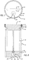
FIG. 1 is a perspective view of a manual mixer according to an embodiment of the present invention; -
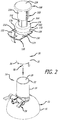
FIG. 2 is a partially-exploded perspective view of the manual mixer ofFIG. 1 ; -
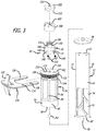
FIG. 3 is an exploded perspective view of a mixing assembly of the manual mixer ofFIG. 1 ; -
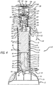
FIG. 4 is a cross-sectional view of the manual mixer ofFIG. 1 showing a plunger portion thereof in an upper first position; -
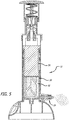
FIG. 5 is a cross-sectional view of the manual mixer similar toFIG. 4 showing the plunger portion in an intermediate position; -
FIG. 6 is a cross-sectional view of the manual mixer similar toFIGS. 4 and5 showing the plunger portion in a lower second position; -
FIG. 7 is a bottom plan view of the plunger portion of the manual mixer ofFIG. 1 showing a check valve; and -
FIG. 8 is a cross-sectional view of the plunger portion of the manual mixer ofFIG. 1 showing the check valve. - In accordance with one preferred embodiment of the present invention, and as depicted in
FIGS. 1 ,2 , and4-6 , amanual mixer 10 is provided for mixing and agitating materials for use during surgery. - As depicted in
FIGS. 1 ,2 , and4 , themanual mixer 10 includes abase portion 12, and thebase portion 12 includes afirst sidewall portion 14 and apedestal portion 16. Thefirst sidewall portion 14 extends upwardly from thepedestal portion 16, and thepedestal portion 16 serves as a stand allowing thebase portion 12 to remain upright. Thefirst sidewall portion 14 is hollow and in part defines a firstinterior cavity 18 having a closedfirst end 20, an opensecond end 22, and aninterior surface 24. Theinterior surface 24 can be cylindrical. Furthermore, thepedestal portion 16 includes adepression 26 formed therein, and thedepression 26 communicates with the firstinterior cavity 18. - As discussed below, the first
interior cavity 18 along with other portions of themanual mixer 10 is provided to receive materials (including liquids, pastes, and/or solids) that can be mixed and agitated by themanual mixer 10 prior to use during surgery or other medical procedures. As such, the firstinterior cavity 18 serves as a mixing chamber. An example of a material that can be mixed using themanual mixer 10 is a bone cement such as polymethyl methacrylate (PMMA). Thebase portion 12 includes avalve assembly 28, and as discussed below, thevalve assembly 28 can be closed to facilitate mixing and agitating the materials in the mixing chamber, and can be opened to facilitate dispensing of the materials from the mixing chamber. - The
manual mixer 10, as depicted inFIGS. 1 ,2 , and4 , also includes abody portion 30, and thebody portion 30 includes asecond sidewall portion 32. Thesecond sidewall portion 32 extends upwardly from adjacent thepedestal portion 16. Thesecond sidewall portion 32 is hollow and in part defines a secondinterior cavity 34 having an openfirst end 36, an opensecond end 38, and aninterior surface 40. Like theinterior surface 24, theinterior surface 40 can be cylindrical. Thesecond sidewall portion 32 includesthreads 42 formed along a portion of theinterior surface 40. - The
base portion 12 and thebody portion 30 are removably attached to one another. To facilitate such removable attachment, a portion of thefirst sidewall portion 14 is received within the secondinterior cavity 34. As depicted inFIG. 4 , when thebase portion 12 and thebody portion 30 are attached, portions of thefirst sidewall portion 14 and thesecond sidewall portion 32 overlap one another, a seal is created between thebase portion 12 and thebody portion 30, and the firstinterior cavity 18 and the secondinterior cavity 34 communicate with one another through the opensecond end 38. Furthermore, when thebase portion 12 and thebody portion 30 are detached, access is provided to the firstinterior cavity 18, and the firstinterior cavity 18 can receive the materials that are to be mixed and agitated by themanual mixer 10. - The
manual mixer 10, as depicted inFIGS. 3 and4 , also includes amixing assembly 50 provided in portions of the firstinterior cavity 18 and the secondinterior cavity 34 for mixing and agitating the materials provided therein. Themixing assembly 50 includes apaddle portion 52, aplunger portion 54, and acoupler portion 56. - The
paddle portion 52 is capable of rotating within portions of the firstinterior cavity 18 and the secondinterior cavity 34. Thepaddle portion 52 includes a lowerfirst end 60, an opposite uppersecond end 62, a length between the lowerfirst end 60 and the uppersecond end 62, and an axis of rotation A extending along the length and through the lowerfirst end 60 and the uppersecond end 62. Thepaddle portion 52 also includes afirst surface 64, an opposite second surface (not shown), afirst edge 70, and an oppositesecond edge 72. Thefirst surface 64 and the second surface can each be planar or curved, the horizontal widths of thepaddle portion 52 between thefirst edge 70 and thesecond edge 72 can be constant or variable, the horizontal widths are also less than the minimum side-to-side dimensions of the firstinterior cavity 18 and the secondinterior cavity 34, and thepaddle portion 52 can include one ormore openings 74 extending between thefirst surface 64 and the second surface. Thefirst surface 64 and the second surface can be substantially planar, the horizontal widths between thefirst edge 70 and thesecond edge 72 can be substantially constant, and thepaddle portion 52 can include four (4)openings 74 of various shapes and sizes. The asymmetrical arrangement and shapes of theopenings 74 are provided to inhibit theplunger portion 54 from getting caught on thepaddle portion 52. The asymmetrical arrangement and shapes of the openings are provided to facilitate improved mixing and agitating of the materials. In an alternative embodiment, the shape of theopenings 74 and arrangement thereof can be identical and/or symmetrical. - The lower
first end 60 of thepaddle portion 52 includes aprojection 68. As depicted inFIG. 4 , theprojection 68 can be received in thedepression 26, and theprojection 68 serves as the point of support for the rotation of thepaddle portion 52 about the axis of rotation A. The rotation of thepaddle portion 52 and the interaction of the materials in the firstinterior cavity 18 mixes and agitates the materials due to contact thereof with thefirst surface 64 and the second surface, the passage thereof around thefirst edge 70 and thesecond edge 72, and the passage thereof through theopenings 74. - The
plunger portion 54 is moveable along and rotates with thepaddle portion 52. Theplunger portion 54 is moveable along thepaddle portion 52 between an upper first position (FIG. 4 ) and a lower second position (FIG. 6 ) and proceeds through various intermediate positions (e.g.,FIG. 5 ) relative to the firstinterior cavity 18 and the secondinterior cavity 34. As depicted inFIGS. 3 and4 , theplunger portion 54 includes afirst end portion 80, an oppositesecond end portion 82, aweb portion 84 extending between thefirst end portion 80 and thesecond end portion 82, and first andsecond support struts 86 and 88 (not shown) on either side of theweb portion 84. Thefirst end portion 80 includes afirst end surface 90 and anouter surface 92, and thesecond end portion 82 includes asecond end surface 100, anouter surface 102, and adepression 104 adjacent theouter surface 102. - The
first end surface 90 is circular and theouter surface 92 is cylindrical. Thefirst end surface 90 can be provided on aseal 94 attached to thefirst end portion 80. Thefirst end surface 90 contacts the materials received in the firstinterior cavity 18 as theplunger portion 54 moves from the upper first position to the lower second position, and theseal 94 and theouter surface 92 form a seal with theinterior surface 24 to prevent the materials from leaking past thefirst end portion 80. Furthermore, theouter surface 102 is cylindrical and includesthreads 106 therearound. As discussed below, thethreads 106 are provided for engagement to thethreads 42 formed on theinterior surface 40 of thesecond sidewall portion 32. - A
passageway 110 extends through theplunger portion 54 between afirst opening 112 in thefirst end surface 90 and asecond opening 114 in thesecond end surface 100. In doing so, thepassageway 110 traverses through the first end portion 80 (and the seal 94), and then theweb portion 84, and then thesecond end portion 82. At least a portion of thepaddle portion 52 is received in thepassageway 110 to attach thepaddle portion 52 and theplunger portion 54 to one another, and, as discussed above, theplunger portion 54 is moveable along thepaddle portion 52 between the upper first position and the lower second position. Theseal 94 serves in preventing the material from the firstinterior cavity 18 from entering thepassageway 110 through thefirst opening 112 as theplunger portion 54 moves along thepaddle portion 52. Furthermore, theplunger portion 54 is capable of rotating with thepaddle portion 52 as it moves between the upper first position and the lower second position. - The
plunger portion 54 is maintained in the first upper position by aclamp portion 120, and in the first upper position, thethreads 42 and thethreads 106 are disengaged from one another. As depicted inFIGS. 1-3 , theclamp portion 120 includes ahandle portion 122 and aU-shaped portion 124 having afirst arm 126 and asecond arm 128. Thesecond sidewall portion 32 includes afirst slot 130 and asecond slot 132 on opposite sides thereof. Thefirst slot 130 and thesecond slot 132 communicate with the secondinterior cavity 34, and afford partial insertion of thefirst arm 126 and thesecond arm 128 into the secondinterior cavity 34 to engage thedepression 104 formed on theplunger portion 54. For example, when theclamp portion 120 is engaged to thedepression 104, thefirst arm 126 is received through thefirst slot 130 to engage thedepression 104, and thesecond arm 128 is received through thesecond slot 132 to engage thedepression 104. Theplunger portion 54 is capable of rotation with theclamp portion 120 engaged thereto. Thus, theclamp portion 120 holds theplunger portion 54 in the upper first position, while simultaneously allowing theplunger portion 54 to rotate with the rotation of thepaddle portion 52. When theclamp portion 120 is disengaged from thedepression 104 and removed from the remainder of themanual mixer 10, theplunger portion 54 drops downwardly from the first upper position to engage thethreads 42 and thethreads 106 with one another. Due to the interaction of thethreads 42 and thethreads 106, rotation of theplunger portion 54 with rotation of thepaddle portion 52 causes theplunger portion 54 to translate downwardly toward the second lower portion. - The
coupler portion 56 includes afirst portion 140 and asecond portion 142. As depicted inFIGS. 3 and4 , thefirst portion 140 includes aflange portion 144, afirst extension portion 146 extending downwardly from theflange portion 144, and aslot 148 provided through thefirst extension portion 146, and thesecond portion 142 includes asecond extension portion 150 extending upwardly from theflange portion 144. A portion of thepaddle portion 52 is received in theslot 148, andfasteners 152 can be received through thefirst extension portion 146 and thepaddle portion 52 to attach thepaddle portion 52 to thecoupler portion 56. Furthermore, thesecond extension portion 150 is cylindrical and includes threads 154 for engagement to anactuation assembly 160 used to rotate thepaddle portion 52 and theplunger portion 54. As such, thesecond extension portion 150 and the threads 154 serve as a coupler facilitating engagement of thecoupler portion 56 to theactuation assembly 160. - The
actuation assembly 160 includes acap portion 162, atransmission housing 164, atransmission 166, abutton portion 168, and adrive shaft 170. Thecap portion 162, as depicted inFIG. 4 , includes asidewall portion 172, atop portion 174 extending between thesidewall portion 172, and anaperture 176 formed through thetop portion 174. Thecap portion 162 is received over thesecond sidewall portion 32 to enclose the secondinterior cavity 34, and thesecond extension portion 150 of thecoupler portion 56 is received through theaperture 176. - The
transmission housing 164, as depicted inFIG. 4 , includes an openfirst end 180, an opensecond end 182, asidewall potion 184 extending from the openfirst end 180 toward the opensecond end 182, aflange portion 186 at the opensecond end 182, and an interior cavity 188 extending between the openfirst end 180 and the opensecond end 182. Thesidewall portion 184 at the openfirst end 180 can be attached to thetop portion 174 of thecap portion 162. The interior cavity 188 includes a lowerfirst portion 190 and an uppersecond portion 192. The lowerfirst portion 190 receives a portion of thesecond extension portion 150, thetransmission 166, and a portion of thedrive shaft 170 therein. The uppersecond portion 192 receives a portion of thedrive shaft 170 therein. Furthermore, theflange portion 186 is used to facilitate attachment of thebutton portion 168 to thetransmission housing 164. - The
transmission 166, as depicted inFIG. 4 , includes afirst gear 200 attached to thesecond extension portion 150, and asecond gear 202 attached to thedrive shaft 170. Thefirst gear 200 includes anaperture 204,threads 206 provided in theaperture 204, and a first set ofteeth 208, and thesecond gear 202 includes anaperture 210 and a second set ofteeth 212. The threads 154 can engage thethreads 206 to attach thesecond extension portion 150 to thefirst gear 200, and thedrive shaft 170 can be received in theaperture 210 to attach thedrive shaft 170 to thesecond gear 202. The first set ofteeth 208 and the second set ofteeth 212 can matingly engage one another, and when engaged, rotation of thesecond gear 202 causes corresponding rotation of thefirst gear 200. - The
button portion 168, as depicted inFIG. 4 , includes an openfirst end 220, a closedsecond end 222, asidewall portion 224 extending from the openfirst end 220 toward the closedsecond end 222, ahandhold portion 226 at the closedsecond end 222, and aninterior cavity 228 extending from the openfirst end 220 toward the closedsecond end 222. Thebutton portion 168 is moveable between an upper first position and a lower second position relative to thetransmission housing 164, and depending on the position of thebutton portion 168 more or less of thetransmission housing 164 is received in theinterior cavity 228. - A
spring 230 having afirst end 232 and asecond end 234 is provided in theinterior cavity 228. Thefirst end 232 engages atop surface 236 of theflange portion 186, and thesecond end 234 engages an upperinterior surface 238 of theinterior cavity 228 adjacent thehandhold portion 226. Thespring 230 biases thebutton portion 168 in the upper first position. Furthermore, the upperinterior surface 238 includes aprojection portion 240 extending into theinterior cavity 228. Thedrive shaft 170 is attached to theprojection portion 240 using afastener 242. As such, thedrive shaft 170 moves with thebutton portion 168. When thehandhold portion 226 is moved downwardly, thedrive shaft 170 also moves downwardly, and when thehandhold portion 226 is moved upwardly, thedrive shaft 170 also moves upwardly. - As discussed below, downward strokes of the
button portion 168 causes downward movement of thedrive shaft 170, and the interaction of thedrive shaft 170 with thetransmission 166 due to the movement thereof ultimately causes rotation of thepaddle portion 52 and theplunger portion 54. - As discussed above, the
drive shaft 170 is received through theaperture 210 of thesecond gear 202. The interaction between thedrive shaft 170 and theaperture 210 at times causes thesecond gear 202 to move withdrive shaft 170 and at other times causes thedrive shaft 170 to slide through theaperture 210. Friction between thedrive shaft 170 and the walls of theaperture 210 causes thesecond gear 202 to move with thedrive shaft 170, and overcoming the friction between thedrive shaft 170 and the walls of theaperture 210 causes thedrive shaft 170 to slide through theaperture 210. - When the
button portion 168 is in the upper first position, thedrive shaft 170 is located at an uppermost position and thesecond gear 202 is disengaged from thefirst gear 200. When thebutton portion 168 is depressed downward toward the lower second position, thedrive shaft 170 is moved downwardly and friction causes thesecond gear 202 to move downwardly with thedrive shaft 170. Such downward movement causes thesecond gear 202 to engage thefirst gear 200. In doing so, the first set ofteeth 208 and the second set ofteeth 212 are matingly engaged with one another. After engagement of thesecond gear 202 with thefirst gear 200, further downward movement of thebutton portion 168 causes thedrive shaft 170 to slide through theaperture 210. Due to the helical shape of thedrive shaft 170, sliding movement of thedrive shaft 170 through theaperture 210 causes thesecond gear 202 to rotate in a first direction. Thus, pushing thebutton portion 168 downwardly causes rotation of thesecond gear 202 and corresponding rotation of thefirst gear 200 in the first direction. Becausefirst gear 200 is attached to thecoupler portion 56, and thecoupler portion 56 is attached to thepaddle portion 52, such rotation causes rotation of thepaddle portion 52 and theplunger portion 54 in the first direction. - When the
button portion 168 is released, thespring 230 causes thebutton portion 168 to return to the upper first position. Releasing thebutton portion 168 also disengages thesecond gear 202 from thefirst gear 200 to prevent further rotation of thefirst gear 200 in the first direction or in an opposite second direction. As such, rotation of the first gear 200 (and ultimately rotation of thepaddle portion 52 and the plunger portion 54) only occurs during downward strokes of thebutton portion 168. - As depicted in
FIGS. 7 and 8 , theplunger portion 54 can include aball check valve 250 to facilitate release of air contained in the firstinterior cavity 18. Theball check valve 250 includes aball 252, acavity 254 for receiving theball 252, and awasher 256 for containing theball 252 in thecavity 254. Thecavity 254 is formed in a portion of thefirst end portion 80 and can be conical. Thecavity 254 communicates with both the firstinterior cavity 18 via anaperture 258 in thefirst end surface 90 and atmosphere via passages provided at or adjacent the apex of thecavity 254. Thewasher 256 holds theball 252 in thecavity 254, while still allowing air and the material from the firstinterior cavity 18 to enter thecavity 254. As theplunger portion 54 translates downwardly, air from the firstinterior cavity 18 enters thecavity 254. Air entering thecavity 254 does not have enough pressure to push theball 252 upwardly to cover the passages provided at the apex of thecavity 254. Thus, air entering thecavity 254 from the firstinterior cavity 18 can be vented to atmosphere. However, when the materials from the firstinterior cavity 18 enter thecavity 254, the materials do have enough pressure to push theball 252 upwardly to cover the passages provided at the apex of thecavity 254. As such, theball check valve 250 allows air from the firstinterior cavity 18 to vent to atmosphere, but also prevents the materials from the firstinterior cavity 18 from escaping therefrom. - During use of the
manual mixer 10, thebase portion 12 and thebody portion 30 are initially detached from one another to afford access to the firstinterior cavity 18. As discussed above, the firstinterior cavity 18 serves as a mixing chamber. As such, the firstinterior cavity 18 can be filled with the materials requiring mixing and agitated by themanual mixer 10. Once filled with a selected amount of the materials, thebase portion 12 and thebody portion 30 can be attached to one another. As discussed above, a seal is created between thebase portion 12 and thebody portion 30 when attached to one another. The seal serves in preventing the materials from escaping the interior cavity. - To initially mix and agitate the materials in the first
interior cavity 18, theclamp portion 120 is engaged to themanual mixer 10, and thevalve assembly 28 is closed to facilitate containment of the materials in the firstinterior cavity 18 during such mixing and agitating. As discussed above, theclamp portion 120 holds theplunger portion 54 in the upper first position, while simultaneously allowing theplunger portion 54 to rotate with the rotation of thepaddle portion 52. Actuation of theactuation assembly 160 rotates thepaddle portion 52 and theplunger portion 54, and rotation of thepaddle portion 52 in the firstinterior cavity 18 serves to mix and agitate the materials received therein. Thevalve assembly 28 is closed to facilitate containment of the materials in the firstinterior cavity 18 during such mixing and agitating. - When mixing and agitating is determined to be complete, the
clamp portion 120 is disengaged from themanual mixer 10, and thevalve assembly 28 is opened to facilitate dispending of the materials from the firstinterior cavity 18. After disengagement of theclamp portion 120, theplunger portion 54 drops downwardly from the first upper portion to engage thethreads 42 and thethreads 106 with one another. As discussed above, due to the interaction of thethreads 42 and thethreads 106, rotation of thepaddle portion 52 andplunger portion 54 causes theplunger portion 54 to move downwardly toward the second lower portion. The downward translation of theplunger portion 54 forces the materials in the firstinterior cavity 18 to be dispensed through thevalve assembly 28. When theplunger portion 54 completes its translation to the lower second position, the material in the firstinterior cavity 18 will have been fully dispensed therefrom with minimal waste material remaining in the firstinterior cavity 18. - Other embodiments of the invention will be apparent to those skilled in the art from consideration of the specification and practice of the invention disclosed herein. It is intended that the specification and examples be considered as exemplary only, with a true scope of the invention being indicated by the following claims.
Claims (13)
- A manual mixer (10) for mixing and agitating materials for use during surgery, the manual mixer (10) comprising:a base portion (12) having a first sidewall portion (14) and a pedestal portion (16), the first sidewall portion (14) extending upwardly from the pedestal portion (16) and defining at least in part a first interior cavity (18);a body portion (30) having a second sidewall portion (32), the second sidewall portion (32) extending upwardly from adjacent the pedestal portion (16) and defining at least in part a second interior cavity (34), an interior surface (40) of the second sidewall portion (32) including first threads (42), and a portion of first sidewall portion (14) being received with the second interior cavity (34);a mixing assembly (50) having a paddle portion (52) and a plunger portion (54), the paddle portion (52) and the plunger portion (54) being provided in portions of the first interior cavity (18) and the second interior cavity (34), the paddle portion (52) including a lower first end (60), an opposite upper second end (62), a length between the lower first end (60) and the upper second end (62), a first side, an opposite second side, and at least one opening (74) extending through the paddle portion (52) between the first side and the second side, the plunger portion (54) including a first end portion (80), an opposite second end portion (82), a length between the first end portion (80) and the second end portion (82), a first end surface (90), an opposite second end surface (100), a first aperture (112) in the first end surface (90), a second aperture (114) in the second end surface (100), a passageway (110) extending between the first aperture (112) and the second aperture (114), characterized in that it further comprises second threads (106) positioned adjacent the second end portion (82) for engaging the first threads (42) formed on the interior surface (40), at least a portion of the paddle portion (52) being received in the passageway (110) to moveably attach the plunger portion (54) to the paddle portion (52), the plunger portion (54) being moveable along the paddle portion (52) between an upper first position and a lower second position; andan actuation assembly (160) having a transmission housing (164), a transmission (166), and a drive shaft (170), the transmission housing (164) including a third sidewall portion (184), the third sidewall portion (184) extending upwardly from adjacent the second sidewall portion (32) and defining a third interior cavity (188), the transmission (166) and a portion of the drive shaft (170) being received in the third interior cavity (188), the transmission (166) being operatively engaged to the drive shaft (170) and the paddle portion (52);wherein, when the first threads (42) and the second threads (106) are engaged with one another, actuation of the actuation assembly (160) causes linear movement of the drive shaft (170), and the linear movement of the drive shaft (170) is translated into rotational movement by the transmission (166) causing corresponding rotation of the paddle portion (52) and the plunger portion (54) moveably attached to the paddle portion (52), and causing translation of the plunger portion (54) toward the lower second position due to the interaction of the first threads (42) and the second threads (106).
- The manual mixer (10) of claim 1, further comprising a clamp portion (120) receivable in the second interior cavity (34) for engaging the plunger portion (54) to maintain the plunger portion (54) in the upper first position.
- The manual mixer (10) of claim 2, wherein, when the clamp portion (120) is received in the second interior cavity (34) and engaged to the plunger portion (54), the first threads (42) and the second threads (106) are disengaged from one another, and the plunger portion (54) remains in the upper first position during rotation thereof.
- The manual mixer (10) of claim 3, wherein the paddle portion (52) includes a first substantially planar surface (64) on the first side, a second substantially planar surface on the second side, and the at least one opening (74) extending through the paddle portion (52) between the first substantially planar first surface (64) and the second substantially planar second surface; and wherein, when the clamp portion (120) is removed from the second interior cavity (34) and disengaged from the plunger portion (54), the plunger portion (54) moves downwardly to engage the first threads (42) and the second threads (106), and the plunger portion (54) translates toward the lower second position during rotation thereof due to the interaction of the first threads (42) and the second threads (106).
- The manual mixer (10) of one of claims 1 to 4, wherein the actuation assembly (160) further comprises a button portion (168), the button portion (168) being operatively interconnected via the drive shaft (170) to the transmission (166), and wherein linear movement of the button portion (168) from an upper third position to a lower fourth position actuates the actuation assembly (160) and causes linear movement of the drive shaft (170).
- The manual mixer (10) of claim 5, wherein the button portion (168) includes a fourth sidewall portion (172) and a handhold portion (226), the fourth sidewall portion (172) extending downwardly from the handhold portion (226) and defining at least in part a fourth cavity (228), the button portion (168) being capable of linear movement with respect to the transmission housing (164) between the upper third position and the lower fourth position, a greater amount of transmission housing (164) being received in the fourth cavity (228) when the button portion (168) is in the lower fourth position than when the button portion (168) is in the upper third position.
- The manual mixer (10) of one of claims 1 to 6, wherein the transmission (166) further comprises a first gear (200) connected to the paddle portion (52) and a second gear (202) connected to the drive shaft (170), the second gear (202) being moveable between an upper fifth position where the first gear (200) and the second gear (202) are disengaged from one another, and a lower sixth position where the first gear (200) and the second gear (202) are engaged with one another.
- The manual mixer (10) of claim 7, wherein linear movement of the drive shaft (170) causes movement of the second gear (202) between the upper fifth position and the lower sixth position, and wherein, when the second gear (202) is contacted with the first gear (200) in the lower sixth position, further linear movement of the drive shaft (170) causes rotational movement of the second gear (202) that causes corresponding rotational movement of the first gear (200) and the paddle portion (52) connected to the first gear (200).
- The manual mixer (10) of one of claims 7 or 8, wherein the drive shaft (170) includes a helical portion, and the second gear (202) includes a wall portion and an aperture (210) provided in the wall portion, the aperture (210) being configured to receive the drive shaft (170) therein, interaction between the drive shaft (170) and the aperture (210) due to movement of the drive shaft (170) therethrough causes rotation of the second gear (202).
- The manual mixer (10) of one of claims 1 to 9, wherein the mixing assembly (50) further comprises a coupler portion (56), the coupler portion (56) including a first portion (140) and a second portion (142), the first portion (140) being connected to the paddle portion (52) and the second portion (142) being connected to the first gear (200).
- The manual mixer (10) of one of claims 1 to 10, wherein the base portion (12) further comprises a depression (26) communicating with the first interior cavity (18), and the paddle portion (52) further comprises a projection (68) at the lower first end (60) thereof, the projection (68) being received in the depression (26) of the base portion (12) to facilitate rotation of the paddle portion (52).
- A method of mixing and agitating materials using the manual mixer (10) according to one of claims 1 to 11, the method comprising:providing the manual mixer (10) having the body portion (30), the mixing assembly (50), and the actuation assembly (160), the body portion (30) defining an interior cavity for receiving at least a portion of the mixing assembly (50), the mixing assembly (50) including the paddle portion (52) and the plunger portion (54), a portion of the paddle portion (52) being received within the passageway (110) extending through the plunger portion (54), the plunger portion (54) being moveable downwardly along the paddle portion (52), and the actuation assembly (160) being operatively interconnected with the mixing assembly (50);removing the mixing assembly (50) from the interior cavity;providing the materials to be mixed and agitated in the interior cavity;replacing the mixing assembly (50) in the interior cavity; andactuating the actuation assembly (160) to rotate the paddle portion (52) and the plunger portion (54), and simultaneously move the plunger portion (54) downwardly along the paddle portion (52) within the interior cavity, the rotation of the paddle portion (52) and the plunger portion (54), and downwards movement of the plunger portion (54) serving to mix and agitate the materials provided in the interior cavity.
- The method of claim 12, further comprising expelling the materials from the interior cavity through a valve assembly (28) via downward movement of the plunger portion (54) in the interior cavity.
Applications Claiming Priority (1)
| Application Number | Priority Date | Filing Date | Title |
|---|---|---|---|
| US15/876,256 US10856923B2 (en) | 2018-01-22 | 2018-01-22 | Manual mixer |
Publications (2)
| Publication Number | Publication Date |
|---|---|
| EP3524342A1 EP3524342A1 (en) | 2019-08-14 |
| EP3524342B1 true EP3524342B1 (en) | 2021-01-27 |
Family
ID=64665261
Family Applications (1)
| Application Number | Title | Priority Date | Filing Date |
|---|---|---|---|
| EP18212189.7A Active EP3524342B1 (en) | 2018-01-22 | 2018-12-13 | Manual mixer |
Country Status (4)
| Country | Link |
|---|---|
| US (3) | US10856923B2 (en) |
| EP (1) | EP3524342B1 (en) |
| KR (1) | KR20190089747A (en) |
| AU (1) | AU2018274974B2 (en) |
Families Citing this family (2)
| Publication number | Priority date | Publication date | Assignee | Title |
|---|---|---|---|---|
| US10856923B2 (en) * | 2018-01-22 | 2020-12-08 | Warsaw Orthopedic, Inc. | Manual mixer |
| US20240278203A1 (en) * | 2023-02-17 | 2024-08-22 | Georgia Tech Research Corporation | Manual devices and systems for mixing or separating components of a solution |
Family Cites Families (17)
| Publication number | Priority date | Publication date | Assignee | Title |
|---|---|---|---|---|
| GB9525209D0 (en) | 1995-12-09 | 1996-02-07 | Depuy Int Ltd | Mixing bone cement |
| JP4159202B2 (en) * | 1998-12-21 | 2008-10-01 | 日本特殊陶業株式会社 | Calcium phosphate cement kneading apparatus and method for preparing calcium phosphate cement kneaded material |
| DE20008103U1 (en) | 2000-05-05 | 2001-09-13 | Coripharm Medizinprodukte GmbH & Co. KG., 64807 Dieburg | Preparation and application device for materials, in particular bone cement, to be prepared from at least one powdery or granular and a liquid component immediately before use to form a pasty, flowable mass |
| US6712794B2 (en) * | 2001-08-21 | 2004-03-30 | Spinal Specialties, Inc. | Apparatus for delivering a viscous liquid to a surgical site |
| GB2398741B (en) | 2003-02-05 | 2005-04-13 | Summit Medical Ltd | Orthopaedic cement mixing device |
| US7524103B2 (en) | 2003-11-18 | 2009-04-28 | Boston Scientific Scimed, Inc. | Apparatus for mixing and dispensing a multi-component bone cement |
| US20090281549A1 (en) | 2008-05-12 | 2009-11-12 | Cook Incorporated | Bone cement mixing and delivery device and method of use |
| DE102012024710A1 (en) | 2012-11-07 | 2014-05-08 | Heraeus Medical Gmbh | Device for mixing and discharging a pasty mass |
| GB2514535A (en) | 2013-03-18 | 2014-12-03 | Summit Medical Ltd | An apparatus for mixing and delivering bone cement |
| US9549770B2 (en) * | 2013-10-10 | 2017-01-24 | Biomet Sas | Vacuum indicator system that avoid release without the proper vacuum level |
| DE102013226118B3 (en) | 2013-12-16 | 2015-06-11 | Heraeus Medical Gmbh | Device for storing and mixing bone cement |
| CN105147384B (en) | 2015-07-30 | 2017-06-13 | 苏州爱得科技发展股份有限公司 | Bone cement stirring injects system |
| DE102015116245B4 (en) | 2015-09-25 | 2019-01-31 | Heraeus Medical Gmbh | Apparatus and method for opening glass ampoules and cementing apparatus |
| DE102015116797B4 (en) | 2015-10-02 | 2018-08-23 | Heraeus Medical Gmbh | Apparatus and method for storing and mixing a bone cement |
| US9808775B2 (en) | 2016-01-29 | 2017-11-07 | Kyphon SÀRL | Manual mixer |
| DE102016106261B4 (en) | 2016-04-06 | 2018-03-15 | Heraeus Medical Gmbh | Device for mixing and storing polymethyl methacrylate bone cement with pressure pump and vial breaker |
| US10856923B2 (en) * | 2018-01-22 | 2020-12-08 | Warsaw Orthopedic, Inc. | Manual mixer |
-
2018
- 2018-01-22 US US15/876,256 patent/US10856923B2/en active Active
- 2018-12-06 AU AU2018274974A patent/AU2018274974B2/en active Active
- 2018-12-13 EP EP18212189.7A patent/EP3524342B1/en active Active
-
2019
- 2019-01-18 KR KR1020190006938A patent/KR20190089747A/en active Pending
-
2020
- 2020-11-13 US US17/097,756 patent/US11896276B2/en active Active
-
2024
- 2024-02-12 US US18/439,179 patent/US12419674B2/en active Active
Non-Patent Citations (1)
| Title |
|---|
| None * |
Also Published As
| Publication number | Publication date |
|---|---|
| US20190223932A1 (en) | 2019-07-25 |
| US20240180602A1 (en) | 2024-06-06 |
| AU2018274974B2 (en) | 2024-05-02 |
| US20210059734A1 (en) | 2021-03-04 |
| US11896276B2 (en) | 2024-02-13 |
| US10856923B2 (en) | 2020-12-08 |
| EP3524342A1 (en) | 2019-08-14 |
| US12419674B2 (en) | 2025-09-23 |
| KR20190089747A (en) | 2019-07-31 |
| AU2018274974A1 (en) | 2019-08-08 |
Similar Documents
| Publication | Publication Date | Title |
|---|---|---|
| US12419674B2 (en) | Manual mixer | |
| US10279326B2 (en) | Manual mixer | |
| US5415474A (en) | Bone cement mixing and loading apparatus | |
| DE602004007354T2 (en) | Mixers and cups | |
| JP2000313487A (en) | Portable dispenser for packaging and distributing colored cosmetics | |
| US20170173544A1 (en) | Apparatus for mixing nut butter and the like | |
| JPH04220259A (en) | Mixer and filler for surgical adhesive | |
| WO1999065597A1 (en) | An apparatus for mixing and dispensing ingredients | |
| JPH09511438A (en) | Bone cement mixing device and mixing method | |
| WO2005084591A1 (en) | Apparatus for mixing and discharging bone cement | |
| US20060274601A1 (en) | Prepacked cartridge mixing system | |
| US6874927B2 (en) | Orthopaedic cement mixing and dispensing device | |
| WO2017203233A1 (en) | Bone cement mixer | |
| PL187772B1 (en) | Dispenser with agitator | |
| AU2004210409B2 (en) | Orthopaedic cement mixing device | |
| WO2017203234A1 (en) | Bone cement mixer | |
| JPH0335713Y2 (en) | ||
| GB2430165A (en) | Othopaedic cement mixing device |
Legal Events
| Date | Code | Title | Description |
|---|---|---|---|
| PUAI | Public reference made under article 153(3) epc to a published international application that has entered the european phase |
Free format text: ORIGINAL CODE: 0009012 |
|
| STAA | Information on the status of an ep patent application or granted ep patent |
Free format text: STATUS: THE APPLICATION HAS BEEN PUBLISHED |
|
| AK | Designated contracting states |
Kind code of ref document: A1 Designated state(s): AL AT BE BG CH CY CZ DE DK EE ES FI FR GB GR HR HU IE IS IT LI LT LU LV MC MK MT NL NO PL PT RO RS SE SI SK SM TR |
|
| AX | Request for extension of the european patent |
Extension state: BA ME |
|
| STAA | Information on the status of an ep patent application or granted ep patent |
Free format text: STATUS: REQUEST FOR EXAMINATION WAS MADE |
|
| 17P | Request for examination filed |
Effective date: 20200204 |
|
| RBV | Designated contracting states (corrected) |
Designated state(s): AL AT BE BG CH CY CZ DE DK EE ES FI FR GB GR HR HU IE IS IT LI LT LU LV MC MK MT NL NO PL PT RO RS SE SI SK SM TR |
|
| GRAP | Despatch of communication of intention to grant a patent |
Free format text: ORIGINAL CODE: EPIDOSNIGR1 |
|
| STAA | Information on the status of an ep patent application or granted ep patent |
Free format text: STATUS: GRANT OF PATENT IS INTENDED |
|
| RIC1 | Information provided on ipc code assigned before grant |
Ipc: B01F 15/00 20060101ALI20200616BHEP Ipc: B01F 13/00 20060101AFI20200616BHEP Ipc: B01F 7/32 20060101ALI20200616BHEP Ipc: B01F 15/02 20060101ALI20200616BHEP |
|
| INTG | Intention to grant announced |
Effective date: 20200721 |
|
| GRAS | Grant fee paid |
Free format text: ORIGINAL CODE: EPIDOSNIGR3 |
|
| GRAA | (expected) grant |
Free format text: ORIGINAL CODE: 0009210 |
|
| STAA | Information on the status of an ep patent application or granted ep patent |
Free format text: STATUS: THE PATENT HAS BEEN GRANTED |
|
| AK | Designated contracting states |
Kind code of ref document: B1 Designated state(s): AL AT BE BG CH CY CZ DE DK EE ES FI FR GB GR HR HU IE IS IT LI LT LU LV MC MK MT NL NO PL PT RO RS SE SI SK SM TR |
|
| REG | Reference to a national code |
Ref country code: GB Ref legal event code: FG4D |
|
| REG | Reference to a national code |
Ref country code: CH Ref legal event code: EP |
|
| REG | Reference to a national code |
Ref country code: AT Ref legal event code: REF Ref document number: 1357837 Country of ref document: AT Kind code of ref document: T Effective date: 20210215 |
|
| REG | Reference to a national code |
Ref country code: IE Ref legal event code: FG4D |
|
| REG | Reference to a national code |
Ref country code: DE Ref legal event code: R096 Ref document number: 602018012270 Country of ref document: DE |
|
| REG | Reference to a national code |
Ref country code: NL Ref legal event code: MP Effective date: 20210127 |
|
| REG | Reference to a national code |
Ref country code: LT Ref legal event code: MG9D |
|
| REG | Reference to a national code |
Ref country code: AT Ref legal event code: MK05 Ref document number: 1357837 Country of ref document: AT Kind code of ref document: T Effective date: 20210127 |
|
| PG25 | Lapsed in a contracting state [announced via postgrant information from national office to epo] |
Ref country code: NO Free format text: LAPSE BECAUSE OF FAILURE TO SUBMIT A TRANSLATION OF THE DESCRIPTION OR TO PAY THE FEE WITHIN THE PRESCRIBED TIME-LIMIT Effective date: 20210427 Ref country code: PT Free format text: LAPSE BECAUSE OF FAILURE TO SUBMIT A TRANSLATION OF THE DESCRIPTION OR TO PAY THE FEE WITHIN THE PRESCRIBED TIME-LIMIT Effective date: 20210527 Ref country code: LT Free format text: LAPSE BECAUSE OF FAILURE TO SUBMIT A TRANSLATION OF THE DESCRIPTION OR TO PAY THE FEE WITHIN THE PRESCRIBED TIME-LIMIT Effective date: 20210127 Ref country code: HR Free format text: LAPSE BECAUSE OF FAILURE TO SUBMIT A TRANSLATION OF THE DESCRIPTION OR TO PAY THE FEE WITHIN THE PRESCRIBED TIME-LIMIT Effective date: 20210127 Ref country code: GR Free format text: LAPSE BECAUSE OF FAILURE TO SUBMIT A TRANSLATION OF THE DESCRIPTION OR TO PAY THE FEE WITHIN THE PRESCRIBED TIME-LIMIT Effective date: 20210428 Ref country code: FI Free format text: LAPSE BECAUSE OF FAILURE TO SUBMIT A TRANSLATION OF THE DESCRIPTION OR TO PAY THE FEE WITHIN THE PRESCRIBED TIME-LIMIT Effective date: 20210127 Ref country code: BG Free format text: LAPSE BECAUSE OF FAILURE TO SUBMIT A TRANSLATION OF THE DESCRIPTION OR TO PAY THE FEE WITHIN THE PRESCRIBED TIME-LIMIT Effective date: 20210427 |
|
| PG25 | Lapsed in a contracting state [announced via postgrant information from national office to epo] |
Ref country code: SE Free format text: LAPSE BECAUSE OF FAILURE TO SUBMIT A TRANSLATION OF THE DESCRIPTION OR TO PAY THE FEE WITHIN THE PRESCRIBED TIME-LIMIT Effective date: 20210127 Ref country code: AT Free format text: LAPSE BECAUSE OF FAILURE TO SUBMIT A TRANSLATION OF THE DESCRIPTION OR TO PAY THE FEE WITHIN THE PRESCRIBED TIME-LIMIT Effective date: 20210127 Ref country code: LV Free format text: LAPSE BECAUSE OF FAILURE TO SUBMIT A TRANSLATION OF THE DESCRIPTION OR TO PAY THE FEE WITHIN THE PRESCRIBED TIME-LIMIT Effective date: 20210127 Ref country code: PL Free format text: LAPSE BECAUSE OF FAILURE TO SUBMIT A TRANSLATION OF THE DESCRIPTION OR TO PAY THE FEE WITHIN THE PRESCRIBED TIME-LIMIT Effective date: 20210127 Ref country code: RS Free format text: LAPSE BECAUSE OF FAILURE TO SUBMIT A TRANSLATION OF THE DESCRIPTION OR TO PAY THE FEE WITHIN THE PRESCRIBED TIME-LIMIT Effective date: 20210127 |
|
| PG25 | Lapsed in a contracting state [announced via postgrant information from national office to epo] |
Ref country code: IS Free format text: LAPSE BECAUSE OF FAILURE TO SUBMIT A TRANSLATION OF THE DESCRIPTION OR TO PAY THE FEE WITHIN THE PRESCRIBED TIME-LIMIT Effective date: 20210527 |
|
| REG | Reference to a national code |
Ref country code: DE Ref legal event code: R097 Ref document number: 602018012270 Country of ref document: DE |
|
| PG25 | Lapsed in a contracting state [announced via postgrant information from national office to epo] |
Ref country code: SM Free format text: LAPSE BECAUSE OF FAILURE TO SUBMIT A TRANSLATION OF THE DESCRIPTION OR TO PAY THE FEE WITHIN THE PRESCRIBED TIME-LIMIT Effective date: 20210127 Ref country code: CZ Free format text: LAPSE BECAUSE OF FAILURE TO SUBMIT A TRANSLATION OF THE DESCRIPTION OR TO PAY THE FEE WITHIN THE PRESCRIBED TIME-LIMIT Effective date: 20210127 Ref country code: EE Free format text: LAPSE BECAUSE OF FAILURE TO SUBMIT A TRANSLATION OF THE DESCRIPTION OR TO PAY THE FEE WITHIN THE PRESCRIBED TIME-LIMIT Effective date: 20210127 |
|
| REG | Reference to a national code |
Ref country code: DE Ref legal event code: R079 Ref document number: 602018012270 Country of ref document: DE Free format text: PREVIOUS MAIN CLASS: B01F0013000000 Ipc: B01F0033000000 |
|
| PG25 | Lapsed in a contracting state [announced via postgrant information from national office to epo] |
Ref country code: DK Free format text: LAPSE BECAUSE OF FAILURE TO SUBMIT A TRANSLATION OF THE DESCRIPTION OR TO PAY THE FEE WITHIN THE PRESCRIBED TIME-LIMIT Effective date: 20210127 Ref country code: RO Free format text: LAPSE BECAUSE OF FAILURE TO SUBMIT A TRANSLATION OF THE DESCRIPTION OR TO PAY THE FEE WITHIN THE PRESCRIBED TIME-LIMIT Effective date: 20210127 Ref country code: SK Free format text: LAPSE BECAUSE OF FAILURE TO SUBMIT A TRANSLATION OF THE DESCRIPTION OR TO PAY THE FEE WITHIN THE PRESCRIBED TIME-LIMIT Effective date: 20210127 |
|
| PLBE | No opposition filed within time limit |
Free format text: ORIGINAL CODE: 0009261 |
|
| STAA | Information on the status of an ep patent application or granted ep patent |
Free format text: STATUS: NO OPPOSITION FILED WITHIN TIME LIMIT |
|
| 26N | No opposition filed |
Effective date: 20211028 |
|
| PG25 | Lapsed in a contracting state [announced via postgrant information from national office to epo] |
Ref country code: ES Free format text: LAPSE BECAUSE OF FAILURE TO SUBMIT A TRANSLATION OF THE DESCRIPTION OR TO PAY THE FEE WITHIN THE PRESCRIBED TIME-LIMIT Effective date: 20210127 Ref country code: AL Free format text: LAPSE BECAUSE OF FAILURE TO SUBMIT A TRANSLATION OF THE DESCRIPTION OR TO PAY THE FEE WITHIN THE PRESCRIBED TIME-LIMIT Effective date: 20210127 |
|
| PG25 | Lapsed in a contracting state [announced via postgrant information from national office to epo] |
Ref country code: SI Free format text: LAPSE BECAUSE OF FAILURE TO SUBMIT A TRANSLATION OF THE DESCRIPTION OR TO PAY THE FEE WITHIN THE PRESCRIBED TIME-LIMIT Effective date: 20210127 |
|
| PG25 | Lapsed in a contracting state [announced via postgrant information from national office to epo] |
Ref country code: IT Free format text: LAPSE BECAUSE OF FAILURE TO SUBMIT A TRANSLATION OF THE DESCRIPTION OR TO PAY THE FEE WITHIN THE PRESCRIBED TIME-LIMIT Effective date: 20210127 |
|
| PG25 | Lapsed in a contracting state [announced via postgrant information from national office to epo] |
Ref country code: IS Free format text: LAPSE BECAUSE OF FAILURE TO SUBMIT A TRANSLATION OF THE DESCRIPTION OR TO PAY THE FEE WITHIN THE PRESCRIBED TIME-LIMIT Effective date: 20210527 |
|
| PG25 | Lapsed in a contracting state [announced via postgrant information from national office to epo] |
Ref country code: MC Free format text: LAPSE BECAUSE OF FAILURE TO SUBMIT A TRANSLATION OF THE DESCRIPTION OR TO PAY THE FEE WITHIN THE PRESCRIBED TIME-LIMIT Effective date: 20210127 |
|
| REG | Reference to a national code |
Ref country code: CH Ref legal event code: PL |
|
| REG | Reference to a national code |
Ref country code: BE Ref legal event code: MM Effective date: 20211231 |
|
| PG25 | Lapsed in a contracting state [announced via postgrant information from national office to epo] |
Ref country code: LU Free format text: LAPSE BECAUSE OF NON-PAYMENT OF DUE FEES Effective date: 20211213 Ref country code: IE Free format text: LAPSE BECAUSE OF NON-PAYMENT OF DUE FEES Effective date: 20211213 |
|
| PG25 | Lapsed in a contracting state [announced via postgrant information from national office to epo] |
Ref country code: BE Free format text: LAPSE BECAUSE OF NON-PAYMENT OF DUE FEES Effective date: 20211231 |
|
| PG25 | Lapsed in a contracting state [announced via postgrant information from national office to epo] |
Ref country code: LI Free format text: LAPSE BECAUSE OF NON-PAYMENT OF DUE FEES Effective date: 20211231 Ref country code: CH Free format text: LAPSE BECAUSE OF NON-PAYMENT OF DUE FEES Effective date: 20211231 |
|
| PG25 | Lapsed in a contracting state [announced via postgrant information from national office to epo] |
Ref country code: NL Free format text: LAPSE BECAUSE OF NON-PAYMENT OF DUE FEES Effective date: 20210127 Ref country code: CY Free format text: LAPSE BECAUSE OF FAILURE TO SUBMIT A TRANSLATION OF THE DESCRIPTION OR TO PAY THE FEE WITHIN THE PRESCRIBED TIME-LIMIT Effective date: 20210127 |
|
| PG25 | Lapsed in a contracting state [announced via postgrant information from national office to epo] |
Ref country code: HU Free format text: LAPSE BECAUSE OF FAILURE TO SUBMIT A TRANSLATION OF THE DESCRIPTION OR TO PAY THE FEE WITHIN THE PRESCRIBED TIME-LIMIT; INVALID AB INITIO Effective date: 20181213 |
|
| GBPC | Gb: european patent ceased through non-payment of renewal fee |
Effective date: 20221213 |
|
| PG25 | Lapsed in a contracting state [announced via postgrant information from national office to epo] |
Ref country code: GB Free format text: LAPSE BECAUSE OF NON-PAYMENT OF DUE FEES Effective date: 20221213 |
|
| PG25 | Lapsed in a contracting state [announced via postgrant information from national office to epo] |
Ref country code: MK Free format text: LAPSE BECAUSE OF FAILURE TO SUBMIT A TRANSLATION OF THE DESCRIPTION OR TO PAY THE FEE WITHIN THE PRESCRIBED TIME-LIMIT Effective date: 20210127 |
|
| PG25 | Lapsed in a contracting state [announced via postgrant information from national office to epo] |
Ref country code: TR Free format text: LAPSE BECAUSE OF FAILURE TO SUBMIT A TRANSLATION OF THE DESCRIPTION OR TO PAY THE FEE WITHIN THE PRESCRIBED TIME-LIMIT Effective date: 20210127 |
|
| PG25 | Lapsed in a contracting state [announced via postgrant information from national office to epo] |
Ref country code: MT Free format text: LAPSE BECAUSE OF FAILURE TO SUBMIT A TRANSLATION OF THE DESCRIPTION OR TO PAY THE FEE WITHIN THE PRESCRIBED TIME-LIMIT Effective date: 20210127 |
|
| PGFP | Annual fee paid to national office [announced via postgrant information from national office to epo] |
Ref country code: FR Payment date: 20241219 Year of fee payment: 7 |
|
| PGFP | Annual fee paid to national office [announced via postgrant information from national office to epo] |
Ref country code: DE Payment date: 20251126 Year of fee payment: 8 |