EP3524325A1 - Commercial aviation fire extinguisher - strength increase method for in service and oem fire protection - Google Patents
Commercial aviation fire extinguisher - strength increase method for in service and oem fire protection Download PDFInfo
- Publication number
- EP3524325A1 EP3524325A1 EP18200505.8A EP18200505A EP3524325A1 EP 3524325 A1 EP3524325 A1 EP 3524325A1 EP 18200505 A EP18200505 A EP 18200505A EP 3524325 A1 EP3524325 A1 EP 3524325A1
- Authority
- EP
- European Patent Office
- Prior art keywords
- fire extinguisher
- wrap
- attached
- extinguisher vessel
- vessel
- Prior art date
- Legal status (The legal status is an assumption and is not a legal conclusion. Google has not performed a legal analysis and makes no representation as to the accuracy of the status listed.)
- Granted
Links
Images
Classifications
-
- A—HUMAN NECESSITIES
- A62—LIFE-SAVING; FIRE-FIGHTING
- A62C—FIRE-FIGHTING
- A62C35/00—Permanently-installed equipment
- A62C35/02—Permanently-installed equipment with containers for delivering the extinguishing substance
- A62C35/023—Permanently-installed equipment with containers for delivering the extinguishing substance the extinguishing material being expelled by compressed gas, taken from storage tanks, or by generating a pressure gas
-
- A—HUMAN NECESSITIES
- A62—LIFE-SAVING; FIRE-FIGHTING
- A62C—FIRE-FIGHTING
- A62C3/00—Fire prevention, containment or extinguishing specially adapted for particular objects or places
- A62C3/07—Fire prevention, containment or extinguishing specially adapted for particular objects or places in vehicles, e.g. in road vehicles
- A62C3/08—Fire prevention, containment or extinguishing specially adapted for particular objects or places in vehicles, e.g. in road vehicles in aircraft
-
- B—PERFORMING OPERATIONS; TRANSPORTING
- B65—CONVEYING; PACKING; STORING; HANDLING THIN OR FILAMENTARY MATERIAL
- B65D—CONTAINERS FOR STORAGE OR TRANSPORT OF ARTICLES OR MATERIALS, e.g. BAGS, BARRELS, BOTTLES, BOXES, CANS, CARTONS, CRATES, DRUMS, JARS, TANKS, HOPPERS, FORWARDING CONTAINERS; ACCESSORIES, CLOSURES, OR FITTINGS THEREFOR; PACKAGING ELEMENTS; PACKAGES
- B65D25/00—Details of other kinds or types of rigid or semi-rigid containers
- B65D25/34—Coverings or external coatings
Definitions
- the present disclosure relates to fire suppression systems, and in particular, to fire extinguisher vessels.
- Aircraft fire suppression systems incorporate pressurized fire extinguisher vessels containing fire extinguishing agent.
- the fire extinguisher vessels are installed into the cargo bay or the engine/APU areas of the aircraft.
- Current fire suppression systems on aircraft use Halon as the fire extinguishing agent, and therefore the fire extinguisher vessels are built to accommodate Halon. Because Halon is a very efficient fire extinguishing agent, less Halon is required to extinguish a fire than other less efficient fire extinguishing agents. As a result, current fire extinguisher vessels on aircraft may not be capable of incorporating sufficient fire extinguishing agents other than Halon.
- a fire extinguisher vessel includes a hollow body made of stainless steel, a fill port attached to a first end of the body, a discharge outlet attached to a second end of the body, a mechanical attachment lug connected to the body between the first end of the body and the second end of the body, a pressure switch attached to the body between the mechanical attachment lug and the discharge outlet, and a wrap covering the body. The wrap is flush with the fill port, the discharge outlet, the mechanical attachment lug, and the pressure switch.
- a fire extinguisher vessel includes a hollow body made of stainless steel, a fill port attached to a first end of the body, a discharge outlet attached to a second end of the body, a mechanical attachment lug attached to the body between the first end of the body and the second end of the body, a pressure switch attached to the body between the mechanical attachment lug and the discharge outlet, and a wrap covering the body.
- the wrap comprises high strength fiberglass.
- the fire extinguisher vessel has an agent fill density of at least about 0.026 pounds per cubic inch.
- a method of retrofitting a fire extinguisher vessel includes removing a fire extinguisher vessel from a location on an aircraft.
- the fire extinguisher vessel includes a hollow body made of stainless steel, a fill port attached to a first end of the body, a discharge outlet attached to a second end of the body, a mechanical attachment lug attached to the body between the first end of the body and the second end of the body, and a pressure switch attached to the body between the mechanical attachment lug and the discharge outlet.
- the method further includes wrapping a high strength fiberglass wrap around the body and reinstalling the fire extinguisher vessel into the location on the aircraft.
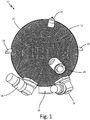
- FIG. 1 is an isometric view of a fire extinguisher vessel.
- the present disclosure describes a fire extinguisher vessel for an aircraft that has been retrofitted with a wrap comprising high strength fiberglass, such as carbon fiber nano-tube, in order to increase the agent fill density of the fire extinguisher vessel such that the fire extinguisher vessel is capable of containing a higher volume of fire extinguishing agent.
- the wrap surrounds the appendages of the fire extinguisher vessel such that the wrap is flush with the appendages.
- the retrofitted vessel is capable of being reinstalled in the same place on the aircraft from which it was removed prior to being fitted with the wrap.
- FIG. 1 is an isometric view of fire extinguisher vessel 10.
- Fire extinguisher vessel 10 includes body 12, fill port 14, discharge outlets 16, mechanical attachment lugs 18, pressure switch 20, and wrap 22.
- Fire extinguisher vessel 10 has hollow spherical body 12.
- Body 12 is a stainless steel container.
- Body 12 may be made of a nitrogen strengthened stainless steel alloy such as Nitronic 40, or any other suitable stainless steel.
- body 12 may be an elongated sphere, cylinder with rounded edges, or any other suitable shape.
- Fill port 14 is attached to an exterior surface of body 12 at a first end of body 12.
- Discharge outlets 16 are attached to the exterior surface of body 12 at a second end of body 12.
- fire extinguisher vessel 10 has three discharge outlets 16.
- fire extinguisher vessel 10 may have more or less than three discharge outlets 16.
- Mechanical attachment lugs 18 are connected to the exterior surface body 12 between the first end of body 12 and the second end of body 12.
- Mechanical attachment lugs 18 are spaced from one another along a circumference of body 12.
- fire extinguisher vessel 10 includes three mechanical attachment lugs 18.
- fire extinguisher vessel 10 may have more or less than three mechanical attachment lugs 18.
- Mechanical attachment lugs 18 may be U-channel lugs or any other suitable mechanical attachment lugs.
- Pressure switch 20 is attached to the exterior surface of body 12 between discharge outlets 16 and mechanical attachment lugs 18.
- Wrap 22 is positioned on the exterior surface of body 12 such that it covers the exterior surface of body 12. Wrap 22 is flush with fill port 14, discharge outlets 16, mechanical attachment lugs 18, and pressure switch 20. As such, wrap 22 completely surrounds fill port 14, discharge outlets 16, mechanical attachment lugs 18, and pressure switch 20 with no spaces existing between wrap 22 and a base of fill port 14, wrap 22 and bases of discharge outlets 16, wrap 22 and bases of mechanical attachment lugs 18, or wrap 22 and a base of pressure switch 20.
- Wrap 22 is made up of a high strength fiberglass material such as carbon fiber nano-tubes or carbon fiber reinforced fiberglass. Wrap 22 has a thickness between about 0.0625 inch (0.15875 centimeter) and about 0.125 inch (0.3175 centimeter).
- Wrap 22 is wrapped around body 12 along all three orthogonal axes of body 12, including along the x-axis, the y-axis, and the z-axis.
- a machine may be used to wrap wrap 22 around fire extinguisher vessel 10, the machine possibly including rollers over which wrap 22 is initially stretched.
- Fire extinguisher vessel 10 has a post installation agent fill density of at least about 0.026 pounds per cubic inch (0.00072 kilograms per cubic centimeter) and up to about 0.0336 pounds per cubic inch (0.000929 kilograms per cubic centimeter).
- Fill port 14 is utilized to fill hollow body 12 with liquid fire extinguishing agent under pressure.
- shock waves are sent into body 12, causing a diaphragm, or burst disc, inside body 12 to rupture and discharge the fire extinguishing agent that is being held under pressure.
- the fire extinguishing agent exits body 12 from the hollow portion of body 12 via discharge outlets 16.
- Mechanical attachment lugs 18 are used to mount fire extinguisher vessel 10 to a location within an aircraft.
- Pressure switch 20 monitors the pressure of fire extinguisher vessel 10 on the aircraft to identify if a leak occurs. Because wrap 22 is flush with fill port 14, discharge outlets 16, mechanical attachment lugs 18, and pressure switch 20, there are no localized stresses created in fire extinguisher vessel 10. Wrap 22 is wrapped along all three orthogonal axes to increase the strength of wrap 22.
- Halon is currently used as the fire extinguishing agent onboard aircraft.
- Halon is a very efficient fire extinguishing agent.
- Halon is also recognized as depletory to the ozone, contributing to the global warming effect.
- Other known fire extinguishing agents such as, for example, nitrogen, carbon dioxide, and HFC125, are less efficient than Halon.
- a higher volume of such less efficient agents is required for fire extinguishing.
- Most existing fire extinguisher vessels, which have been built for use with Halon would need to be filled with a higher volume of less efficient fire extinguishing agent than they have been rated to accommodate.
- an existing fire extinguisher vessel which has an agent fill density of about 0.0289 pounds per cubic inch (0.0008 kilograms per cubic centimeter) is removed from an aircraft and wrapped with wrap 22.
- Incorporating wrap 22 onto an existing fire extinguisher vessel significantly increases the agent fill density of the fire extinguisher vessel to at least about 0.026 pounds per cubic inch (0.00072 kilograms per cubic centimeter) and up to about 0.0336 pounds per cubic inch (0.000929 kilograms per cubic centimeter), without disturbing the fill port, discharge outlets, mechanical attachment lugs, or pressure switch, which are still exposed and not covered by wrap 22.
- fire extinguisher vessel 10 has a higher agent fill density, fire extinguisher vessel 10 can be filled with a greater volume of less efficient liquid fire extinguishing agent while the size of fire extinguisher vessel 10 remains the same. As such, fire extinguisher vessel 10 can provide the same level of fire protection using a less efficient fire extinguishing agent. At the same time, fire extinguisher vessel 10 remains the appropriate size and continues to have the appropriate non-obstructed appendages necessary to be mountable or reinstalled into the same place on the aircraft, likely using the same existing brackets on the aircraft. Further, because wrap 22 can be installed to an existing fire suppression vessel, fire suppression vessel 10 can be wrapped with wrap 22 at a repair facility or during routine maintenance, reducing cost and time required to switch fire suppression agents on an aircraft.
- a fire extinguisher vessel including a hollow body made of stainless steel; a fill port attached to a first end of the body; a discharge outlet attached to a second end of the body; a mechanical attachment lug connected to the body between the first end of the body and the second end of the body; a pressure switch attached to the body between the mechanical attachment lug and the discharge outlet; and a wrap covering the body, wherein the wrap is flush with the fill port, the discharge outlet, the mechanical attachment lug, and the pressure switch.
- the fire extinguisher vessel of the preceding paragraph can optionally include, additionally and/or alternatively, any one or more of the following features, configurations and/or additional components:
- the wrap comprises high strength fiber glass.
- the wrap comprises carbon fiber reinforced fiberglass.
- the wrap comprises carbon fiber nano-tubes.
- the body is spherical.
- the fire extinguisher vessel includes a plurality of mechanical attachment lugs connected to the body between the first end of the body and the second end of the body; and a plurality of discharge outlets attached to a second end of the body.
- the fire extinguisher vessel has an agent fill density of at least about 0.026 pounds per cubic inch.
- the body comprises a nitrogen strengthened stainless steel alloy.
- the fire extinguisher vessel has an agent fill density of up to about 0.0336 pounds per cubic inch.
- the wrap has a thickness between about 0.0625 inch and about 0.125 inch.
- the wrap covers the body along all three orthogonal axes of the body.
- a fire extinguisher vessel including a hollow body made of stainless steel; a fill port attached to a first end of the body; a discharge outlet attached to a second end of the body; a mechanical attachment lug attached to the body between the first end of the body and the second end of the body; a pressure switch attached to the body between the mechanical attachment lug and the discharge outlet; and a wrap covering the body, wherein the wrap comprises high strength fiberglass; and wherein the fire extinguisher vessel has an agent fill density of at least about 0.026 pounds per cubic inch.
- the fire extinguisher vessel of the preceding paragraph can optionally include, additionally and/or alternatively, any one or more of the following features, configurations and/or additional components:
- the wrap comprises carbon fiber nano-tubes.
- the wrap comprises carbon fiber reinforced fiberglass.
- the wrap is flush with the fill port, the discharge outlet, the mechanical attachment lug, and the pressure switch.
- the body is a hollow sphere comprising a nitrogen strengthened stainless steel alloy.
- a method of retrofitting a fire extinguisher vessel includes removing a fire extinguisher vessel from a location on an aircraft, the fire extinguisher vessel including: a hollow body made of stainless steel; a fill port attached to a first end of the body; a discharge outlet attached to a second end of the body; a mechanical attachment lug attached to the body between the first end of the body and the second end of the body; and a pressure switch attached to the body between the mechanical attachment lug and the discharge outlet; wrapping a high strength fiberglass wrap around the body; and reinstalling the fire extinguisher vessel into the location on the aircraft.
- the method of the preceding paragraph can optionally include, additionally and/or alternatively, any one or more of the following features, configurations and/or additional components:
- the wrap is wrapped around the body such that the wrap is flush with the fill port, the discharge outlet, the mechanical attachment lug, and the pressure switch.
- the fire extinguisher vessel has an agent fill density of at least about 0.026 pounds per cubic inch.
- the wrap is wrapped around the body along the x-axis, the y-axis, and the z-axis of the body, wherein the axes are orthogonal axes.
Landscapes
- Health & Medical Sciences (AREA)
- Public Health (AREA)
- Business, Economics & Management (AREA)
- Emergency Management (AREA)
- Engineering & Computer Science (AREA)
- Mechanical Engineering (AREA)
- Fire-Extinguishing By Fire Departments, And Fire-Extinguishing Equipment And Control Thereof (AREA)
Abstract
Description
- The present disclosure relates to fire suppression systems, and in particular, to fire extinguisher vessels.
- Aircraft fire suppression systems incorporate pressurized fire extinguisher vessels containing fire extinguishing agent. The fire extinguisher vessels are installed into the cargo bay or the engine/APU areas of the aircraft. Current fire suppression systems on aircraft use Halon as the fire extinguishing agent, and therefore the fire extinguisher vessels are built to accommodate Halon. Because Halon is a very efficient fire extinguishing agent, less Halon is required to extinguish a fire than other less efficient fire extinguishing agents. As a result, current fire extinguisher vessels on aircraft may not be capable of incorporating sufficient fire extinguishing agents other than Halon.
- A fire extinguisher vessel includes a hollow body made of stainless steel, a fill port attached to a first end of the body, a discharge outlet attached to a second end of the body, a mechanical attachment lug connected to the body between the first end of the body and the second end of the body, a pressure switch attached to the body between the mechanical attachment lug and the discharge outlet, and a wrap covering the body. The wrap is flush with the fill port, the discharge outlet, the mechanical attachment lug, and the pressure switch.
- A fire extinguisher vessel includes a hollow body made of stainless steel, a fill port attached to a first end of the body, a discharge outlet attached to a second end of the body, a mechanical attachment lug attached to the body between the first end of the body and the second end of the body, a pressure switch attached to the body between the mechanical attachment lug and the discharge outlet, and a wrap covering the body. The wrap comprises high strength fiberglass. The fire extinguisher vessel has an agent fill density of at least about 0.026 pounds per cubic inch.
- A method of retrofitting a fire extinguisher vessel includes removing a fire extinguisher vessel from a location on an aircraft. The fire extinguisher vessel includes a hollow body made of stainless steel, a fill port attached to a first end of the body, a discharge outlet attached to a second end of the body, a mechanical attachment lug attached to the body between the first end of the body and the second end of the body, and a pressure switch attached to the body between the mechanical attachment lug and the discharge outlet. The method further includes wrapping a high strength fiberglass wrap around the body and reinstalling the fire extinguisher vessel into the location on the aircraft.
-
FIG. 1 is an isometric view of a fire extinguisher vessel. - In general, the present disclosure describes a fire extinguisher vessel for an aircraft that has been retrofitted with a wrap comprising high strength fiberglass, such as carbon fiber nano-tube, in order to increase the agent fill density of the fire extinguisher vessel such that the fire extinguisher vessel is capable of containing a higher volume of fire extinguishing agent. The wrap surrounds the appendages of the fire extinguisher vessel such that the wrap is flush with the appendages. The retrofitted vessel is capable of being reinstalled in the same place on the aircraft from which it was removed prior to being fitted with the wrap.
-
FIG. 1 is an isometric view offire extinguisher vessel 10.Fire extinguisher vessel 10 includesbody 12, fillport 14,discharge outlets 16,mechanical attachment lugs 18,pressure switch 20, andwrap 22. -
Fire extinguisher vessel 10 has hollowspherical body 12.Body 12 is a stainless steel container.Body 12 may be made of a nitrogen strengthened stainless steel alloy such as Nitronic 40, or any other suitable stainless steel. In alternate embodiments,body 12 may be an elongated sphere, cylinder with rounded edges, or any other suitable shape.Fill port 14 is attached to an exterior surface ofbody 12 at a first end ofbody 12.Discharge outlets 16 are attached to the exterior surface ofbody 12 at a second end ofbody 12. In this embodiment,fire extinguisher vessel 10 has threedischarge outlets 16. In alternate embodiments,fire extinguisher vessel 10 may have more or less than threedischarge outlets 16.Mechanical attachment lugs 18 are connected to theexterior surface body 12 between the first end ofbody 12 and the second end ofbody 12.Mechanical attachment lugs 18 are spaced from one another along a circumference ofbody 12. In this embodiment,fire extinguisher vessel 10 includes threemechanical attachment lugs 18. In alternate embodiments,fire extinguisher vessel 10 may have more or less than threemechanical attachment lugs 18.Mechanical attachment lugs 18 may be U-channel lugs or any other suitable mechanical attachment lugs.Pressure switch 20 is attached to the exterior surface ofbody 12 betweendischarge outlets 16 andmechanical attachment lugs 18. -
Wrap 22 is positioned on the exterior surface ofbody 12 such that it covers the exterior surface ofbody 12.Wrap 22 is flush withfill port 14,discharge outlets 16,mechanical attachment lugs 18, andpressure switch 20. As such,wrap 22 completely surrounds fillport 14,discharge outlets 16,mechanical attachment lugs 18, andpressure switch 20 with no spaces existing betweenwrap 22 and a base offill port 14,wrap 22 and bases ofdischarge outlets 16,wrap 22 and bases ofmechanical attachment lugs 18, orwrap 22 and a base ofpressure switch 20. Wrap 22 is made up of a high strength fiberglass material such as carbon fiber nano-tubes or carbon fiber reinforced fiberglass. Wrap 22 has a thickness between about 0.0625 inch (0.15875 centimeter) and about 0.125 inch (0.3175 centimeter).Wrap 22 is wrapped aroundbody 12 along all three orthogonal axes ofbody 12, including along the x-axis, the y-axis, and the z-axis. A machine may be used to wrapwrap 22 aroundfire extinguisher vessel 10, the machine possibly including rollers over whichwrap 22 is initially stretched.Fire extinguisher vessel 10 has a post installation agent fill density of at least about 0.026 pounds per cubic inch (0.00072 kilograms per cubic centimeter) and up to about 0.0336 pounds per cubic inch (0.000929 kilograms per cubic centimeter). -
Fill port 14 is utilized to fillhollow body 12 with liquid fire extinguishing agent under pressure. When a cartridge insidebody 12 is activated, shock waves are sent intobody 12, causing a diaphragm, or burst disc, insidebody 12 to rupture and discharge the fire extinguishing agent that is being held under pressure. The fire extinguishing agent exitsbody 12 from the hollow portion ofbody 12 viadischarge outlets 16.Mechanical attachment lugs 18 are used to mountfire extinguisher vessel 10 to a location within an aircraft.Pressure switch 20 monitors the pressure offire extinguisher vessel 10 on the aircraft to identify if a leak occurs. Becausewrap 22 is flush withfill port 14,discharge outlets 16,mechanical attachment lugs 18, andpressure switch 20, there are no localized stresses created infire extinguisher vessel 10.Wrap 22 is wrapped along all three orthogonal axes to increase the strength ofwrap 22. - Halon is currently used as the fire extinguishing agent onboard aircraft. Halon is a very efficient fire extinguishing agent. However, Halon is also recognized as depletory to the ozone, contributing to the global warming effect. As a result, Halon is not being manufactured anymore and is not used in most applications. Other known fire extinguishing agents, such as, for example, nitrogen, carbon dioxide, and HFC125, are less efficient than Halon. A higher volume of such less efficient agents is required for fire extinguishing. Most existing fire extinguisher vessels, which have been built for use with Halon, would need to be filled with a higher volume of less efficient fire extinguishing agent than they have been rated to accommodate.
- In order to retrofit an existing fire extinguisher vessel for use with an agent other than Halon, an existing fire extinguisher vessel, which has an agent fill density of about 0.0289 pounds per cubic inch (0.0008 kilograms per cubic centimeter), is removed from an aircraft and wrapped with
wrap 22. Incorporatingwrap 22 onto an existing fire extinguisher vessel significantly increases the agent fill density of the fire extinguisher vessel to at least about 0.026 pounds per cubic inch (0.00072 kilograms per cubic centimeter) and up to about 0.0336 pounds per cubic inch (0.000929 kilograms per cubic centimeter), without disturbing the fill port, discharge outlets, mechanical attachment lugs, or pressure switch, which are still exposed and not covered bywrap 22. When the fire extinguishing vessel is refilled with a less efficient fire extinguishing agent, a new pressure switch and a new diaphragm, or burst disc, with higher pressure settings are installed. Retrofitfire extinguisher vessel 10 is then reinstalled into the location of the aircraft from which it was removed, fitting into the same space and using the same attachment mechanisms on the aircraft. As a result, the location offire extinguisher vessel 10 on an aircraft does not require modification. - Because
fire extinguisher vessel 10 has a higher agent fill density,fire extinguisher vessel 10 can be filled with a greater volume of less efficient liquid fire extinguishing agent while the size offire extinguisher vessel 10 remains the same. As such,fire extinguisher vessel 10 can provide the same level of fire protection using a less efficient fire extinguishing agent. At the same time,fire extinguisher vessel 10 remains the appropriate size and continues to have the appropriate non-obstructed appendages necessary to be mountable or reinstalled into the same place on the aircraft, likely using the same existing brackets on the aircraft. Further, becausewrap 22 can be installed to an existing fire suppression vessel,fire suppression vessel 10 can be wrapped withwrap 22 at a repair facility or during routine maintenance, reducing cost and time required to switch fire suppression agents on an aircraft. - The following are non-exclusive descriptions of possible embodiments of the present invention.
- A fire extinguisher vessel including a hollow body made of stainless steel; a fill port attached to a first end of the body; a discharge outlet attached to a second end of the body; a mechanical attachment lug connected to the body between the first end of the body and the second end of the body; a pressure switch attached to the body between the mechanical attachment lug and the discharge outlet; and a wrap covering the body, wherein the wrap is flush with the fill port, the discharge outlet, the mechanical attachment lug, and the pressure switch.
- The fire extinguisher vessel of the preceding paragraph can optionally include, additionally and/or alternatively, any one or more of the following features, configurations and/or additional components:
The wrap comprises high strength fiber glass. - The wrap comprises carbon fiber reinforced fiberglass.
- The wrap comprises carbon fiber nano-tubes.
- The body is spherical.
- The fire extinguisher vessel includes a plurality of mechanical attachment lugs connected to the body between the first end of the body and the second end of the body; and a plurality of discharge outlets attached to a second end of the body.
- The fire extinguisher vessel has an agent fill density of at least about 0.026 pounds per cubic inch.
- The body comprises a nitrogen strengthened stainless steel alloy.
- The fire extinguisher vessel has an agent fill density of up to about 0.0336 pounds per cubic inch.
- The wrap has a thickness between about 0.0625 inch and about 0.125 inch.
- The wrap covers the body along all three orthogonal axes of the body.
- A fire extinguisher vessel including a hollow body made of stainless steel; a fill port attached to a first end of the body; a discharge outlet attached to a second end of the body; a mechanical attachment lug attached to the body between the first end of the body and the second end of the body; a pressure switch attached to the body between the mechanical attachment lug and the discharge outlet; and a wrap covering the body, wherein the wrap comprises high strength fiberglass; and wherein the fire extinguisher vessel has an agent fill density of at least about 0.026 pounds per cubic inch.
- The fire extinguisher vessel of the preceding paragraph can optionally include, additionally and/or alternatively, any one or more of the following features, configurations and/or additional components:
The wrap comprises carbon fiber nano-tubes. - The wrap comprises carbon fiber reinforced fiberglass.
- The wrap is flush with the fill port, the discharge outlet, the mechanical attachment lug, and the pressure switch.
- The body is a hollow sphere comprising a nitrogen strengthened stainless steel alloy.
- A method of retrofitting a fire extinguisher vessel includes removing a fire extinguisher vessel from a location on an aircraft, the fire extinguisher vessel including: a hollow body made of stainless steel; a fill port attached to a first end of the body; a discharge outlet attached to a second end of the body; a mechanical attachment lug attached to the body between the first end of the body and the second end of the body; and a pressure switch attached to the body between the mechanical attachment lug and the discharge outlet; wrapping a high strength fiberglass wrap around the body; and reinstalling the fire extinguisher vessel into the location on the aircraft.
- The method of the preceding paragraph can optionally include, additionally and/or alternatively, any one or more of the following features, configurations and/or additional components:
- The wrap is wrapped around the body such that the wrap is flush with the fill port, the discharge outlet, the mechanical attachment lug, and the pressure switch.
- The fire extinguisher vessel has an agent fill density of at least about 0.026 pounds per cubic inch.
- The wrap is wrapped around the body along the x-axis, the y-axis, and the z-axis of the body, wherein the axes are orthogonal axes.
- While the invention has been described with reference to an exemplary embodiment(s), it will be understood by those skilled in the art that various changes may be made and equivalents may be substituted for elements thereof without departing from the scope of the invention. In addition, many modifications may be made to adapt a particular situation or material to the teachings of the invention without departing from the essential scope thereof. Therefore, it is intended that the invention not be limited to the particular embodiment(s) disclosed, but that the invention will include all embodiments falling within the scope of the appended claims.
Claims (15)
- A fire extinguisher vessel comprising:a hollow body made of stainless steel;a fill port attached to a first end of the body;a discharge outlet attached to a second end of the body;a mechanical attachment lug connected to the body between the first end of the body and the second end of the body;a pressure switch attached to the body between the mechanical attachment lug and the discharge outlet; anda wrap covering the body, wherein the wrap is flush with the fill port, the discharge outlet, the mechanical attachment lug, and the pressure switch.
- The fire extinguisher vessel of claim 1, wherein the wrap comprises high strength fiber glass.
- The fire extinguisher vessel of claim 1 or 2, wherein the body is spherical.
- The fire extinguisher vessel of claim 1, 2 or 3, wherein the fire extinguisher vessel includes a plurality of mechanical attachment lugs connected to the body between the first end of the body and the second end of the body; and a plurality of discharge outlets attached to a second end of the body.
- The fire extinguisher vessel of any preceding claim, wherein the body comprises a nitrogen strengthened stainless steel alloy.
- The fire extinguisher vessel of any preceding claim wherein the fire extinguisher vessel has an agent fill density of at least about 0.026 pounds per cubic inch, and/or wherein the fire extinguisher vessel has an agent fill density of up to about 0.0336 pounds per cubic inch.
- The fire extinguisher vessel of any preceding claim, wherein the wrap has a thickness between about 0.0625 inch and about 0.125 inch.
- A fire extinguisher vessel comprising:a hollow body made of stainless steel;a fill port attached to a first end of the body;a discharge outlet attached to a second end of the body;a mechanical attachment lug attached to the body between the first end of the body and the second end of the body;a pressure switch attached to the body between the mechanical attachment lug and the discharge outlet; anda wrap covering the body, wherein the wrap comprises high strength fiberglass; andwherein the fire extinguisher vessel has an agent fill density of at least about 0.026 pounds per cubic inch.
- The fire extinguisher vessel of any preceding claim, wherein the wrap comprises carbon fiber nano-tubes.
- The fire extinguisher vessel of any preceding claim, wherein the wrap comprises carbon fiber reinforced fiberglass.
- The fire extinguisher vessel of any preceding claims, wherein the body is a hollow sphere comprising a nitrogen strengthened stainless steel alloy.
- A method of retrofitting a fire extinguisher vessel comprising:removing a fire extinguisher vessel from a location on an aircraft, the fire extinguisher vessel including:a hollow body made of stainless steel;a fill port attached to a first end of the body;a discharge outlet attached to a second end of the body;a mechanical attachment lug attached to the body between the first end of the body and the second end of the body; anda pressure switch attached to the body between the mechanical attachment lug and the discharge outlet;wrapping a high strength fiberglass wrap around the body; andreinstalling the fire extinguisher vessel into the location on the aircraft.
- The extinguisher or method of any preceding claim, wherein the wrap is wrapped around the body such that the wrap is flush with the fill port, the discharge outlet, the mechanical attachment lug, and the pressure switch.
- The method of claim 12 or 13, wherein the fire extinguisher vessel has an agent fill density of at least about 0.026 pounds per cubic inch.
- The extinguisher or method of any preceding claim, wherein the wrap covers the body along all three orthogonal axes of the body; or wherein the wrap is wrapped around the body along the x-axis, the y-axis, and the z-axis of the body, wherein the axes are orthogonal axes.
Applications Claiming Priority (1)
| Application Number | Priority Date | Filing Date | Title |
|---|---|---|---|
| US15/786,262 US10420969B2 (en) | 2017-10-17 | 2017-10-17 | Commercial aviation fire extinguisher—strength increase method for in service and OEM fire protection |
Publications (2)
| Publication Number | Publication Date |
|---|---|
| EP3524325A1 true EP3524325A1 (en) | 2019-08-14 |
| EP3524325B1 EP3524325B1 (en) | 2024-06-19 |
Family
ID=63862056
Family Applications (1)
| Application Number | Title | Priority Date | Filing Date |
|---|---|---|---|
| EP18200505.8A Active EP3524325B1 (en) | 2017-10-17 | 2018-10-15 | Commercial aviation fire extinguisher - strength increase method for in service and oem fire protection |
Country Status (2)
| Country | Link |
|---|---|
| US (1) | US10420969B2 (en) |
| EP (1) | EP3524325B1 (en) |
Families Citing this family (1)
| Publication number | Priority date | Publication date | Assignee | Title |
|---|---|---|---|---|
| US11918838B2 (en) * | 2019-10-08 | 2024-03-05 | Kidde Technologies, Inc. | Fire suppressant system for aircraft cargo container |
Citations (3)
| Publication number | Priority date | Publication date | Assignee | Title |
|---|---|---|---|---|
| WO1993000961A1 (en) * | 1991-07-11 | 1993-01-21 | Walter Kidde Aerospace, Inc. | Variable pressure regulator for extended fire-extinguishing system |
| CN2126807Y (en) * | 1992-05-23 | 1993-02-10 | 宝鸡消防器材总厂 | Fixed fire-extinguishing bottle for aircraft |
| CN202191621U (en) * | 2011-08-02 | 2012-04-18 | 陕西坚瑞消防股份有限公司 | A kind of automatic fire extinguishing and explosion suppressing bottle |
Family Cites Families (20)
| Publication number | Priority date | Publication date | Assignee | Title |
|---|---|---|---|---|
| US2732017A (en) * | 1956-01-24 | Fire extinguisher for auto tires | ||
| US2779421A (en) * | 1954-06-04 | 1957-01-29 | James H Rust | Aerial fire extinguisher |
| US3375875A (en) * | 1966-04-20 | 1968-04-02 | Fire Boss Inc | Dry chemical fire extinguishing apparatus |
| US3552495A (en) * | 1968-06-06 | 1971-01-05 | American Standard Inc | Fire extinguisher |
| US3994431A (en) | 1975-12-10 | 1976-11-30 | United States Steel Corporation | Method for anchorage and splicing of wires on wire-wrapped cylindrical prestressed structures |
| US4197915A (en) * | 1978-09-29 | 1980-04-15 | Eoudis Martin | Self-righting thrown or rolled spherical fire extinguisher |
| US5385208A (en) * | 1993-04-13 | 1995-01-31 | Baker; R. Arnold | Airborne fire suppressant foam delivery apparatus |
| US6209593B1 (en) * | 1999-09-23 | 2001-04-03 | Carry Manufacturing | Electric in-line snorkel pump for helicopter tanker and method of operation |
| US6796382B2 (en) * | 2001-07-02 | 2004-09-28 | Siam Safety Premier Co., Ltd. | Fire extinguishing ball |
| US7216721B2 (en) * | 2004-08-16 | 2007-05-15 | Emc Packaging, Inc. | Fire extinguisher unit |
| US20060175067A1 (en) * | 2005-02-04 | 2006-08-10 | Cover James N | Fire extinguisher sleeve |
| US20080289831A1 (en) * | 2007-05-25 | 2008-11-27 | Kaimart Phanawatnan Woradech | Fire extinguishing device |
| ES2320845B2 (en) * | 2008-11-10 | 2010-07-01 | Inventec, S.L. | FIRE EXTINGUISHING DEVICE. |
| FR2942969B1 (en) * | 2009-03-10 | 2011-03-04 | Airbus France | FIRE EXTINGUISHING DEVICE FOR AIRCRAFT AND FASTENING METHOD |
| US8342252B2 (en) * | 2009-03-26 | 2013-01-01 | Mohammad Abdullah Alzemi | Automatic fire extinguisher |
| US20110180279A1 (en) * | 2010-01-24 | 2011-07-28 | Lehavot Fire Protection Ltd. | Device and method of protecting a fire extinguisher |
| US9409698B2 (en) | 2011-03-02 | 2016-08-09 | Greenspense Ltd. | Propellant-free pressurized material dispenser |
| WO2013184285A1 (en) | 2012-06-05 | 2013-12-12 | Applied Nanostructured Solutions, Llc | Cns-infused carbon nanomaterials and process therefor |
| WO2015145468A1 (en) | 2014-03-28 | 2015-10-01 | Faber Industrie S.P.A. | Composite-material pressure vessel and system and method for controlling the vessel |
| JP2017115938A (en) | 2015-12-22 | 2017-06-29 | ニッタ株式会社 | High pressure vessel and method for manufacturing high pressure vessel |
-
2017
- 2017-10-17 US US15/786,262 patent/US10420969B2/en active Active
-
2018
- 2018-10-15 EP EP18200505.8A patent/EP3524325B1/en active Active
Patent Citations (3)
| Publication number | Priority date | Publication date | Assignee | Title |
|---|---|---|---|---|
| WO1993000961A1 (en) * | 1991-07-11 | 1993-01-21 | Walter Kidde Aerospace, Inc. | Variable pressure regulator for extended fire-extinguishing system |
| CN2126807Y (en) * | 1992-05-23 | 1993-02-10 | 宝鸡消防器材总厂 | Fixed fire-extinguishing bottle for aircraft |
| CN202191621U (en) * | 2011-08-02 | 2012-04-18 | 陕西坚瑞消防股份有限公司 | A kind of automatic fire extinguishing and explosion suppressing bottle |
Non-Patent Citations (2)
| Title |
|---|
| ANONYMOUS: "First Revision No. 3-NFPA 2001-2016 [ Section No. 1.3 ] Committee Statement National Fire Protection Association Report", 11 May 2016 (2016-05-11), pages 1 - 89, XP055603691, Retrieved from the Internet <URL:https://www.nfpa.org/assets/files/AboutTheCodes/2001/2001_F2017_GFE_AAA_FD_FRStatements.pdf> [retrieved on 20190709] * |
| PAT B MCLAUGHLAN ET AL: "Composite Overwrapped Pressure Vessels, A Primer", 15 October 2011 (2011-10-15), XP055166520, Retrieved from the Internet <URL:https://web.archive.org/web/20111015144240/http://ston.jsc.nasa.gov/collections/TRS/_techrep/SP-2011-573.pdf> [retrieved on 20150202] * |
Also Published As
| Publication number | Publication date |
|---|---|
| EP3524325B1 (en) | 2024-06-19 |
| US20190111292A1 (en) | 2019-04-18 |
| US10420969B2 (en) | 2019-09-24 |
Similar Documents
| Publication | Publication Date | Title |
|---|---|---|
| US10618670B2 (en) | Aircraft propulsion system having at least one anti-fire tank | |
| US3966147A (en) | Hammock supported fuel tank | |
| US6082464A (en) | Dual stage fire extinguisher | |
| US20100230118A1 (en) | Fluid ejection device with reinforced seal | |
| EP2720760B1 (en) | Suppressing a fire condition in a cargo container | |
| US20150325827A1 (en) | Aircraft battery exhaust system | |
| US10420969B2 (en) | Commercial aviation fire extinguisher—strength increase method for in service and OEM fire protection | |
| WO1999004860A1 (en) | Dual stage fire extinguisher | |
| CA2944866C (en) | Fire suppression systems | |
| US20210188457A1 (en) | Assembly for an aircraft, the assembly including a pylon and a tank containing an extinguisher fluid | |
| CN111295230A (en) | Fire suppression system for aircraft | |
| US20160229553A1 (en) | Burst disc device and aircraft | |
| KR20190017963A (en) | Fire extinguisher | |
| US20190151690A1 (en) | Fire metering protection system for aircraft | |
| EP3427798B1 (en) | Fire extinguishers with pressure neutralized internal plates | |
| EP3427800A1 (en) | Fire extinguishers with inverted internal domes | |
| KR101471915B1 (en) | Apparatus for extinguishing forest fire | |
| CA2885112C (en) | Fire supression flow control system apparatus and system | |
| DE102012016847A1 (en) | Assembly housing for surge protection device for use in e.g. electrical installation, has fire-preventing substance containing inert gas, that is filled in housing using filling device | |
| US20220072353A1 (en) | Multi-shot fire metering system | |
| US11918838B2 (en) | Fire suppressant system for aircraft cargo container | |
| EP2964342B1 (en) | Interface between fire suppressant conduit and cargo compartment of an aircraft | |
| EP2496314A1 (en) | Methods and apparatus for dual stage hazard control system | |
| CN120863893A (en) | Protection device for protecting a hydrogen tank and aircraft | |
| KR200155933Y1 (en) | Fuel storage device for aircraft |
Legal Events
| Date | Code | Title | Description |
|---|---|---|---|
| PUAI | Public reference made under article 153(3) epc to a published international application that has entered the european phase |
Free format text: ORIGINAL CODE: 0009012 |
|
| STAA | Information on the status of an ep patent application or granted ep patent |
Free format text: STATUS: THE APPLICATION HAS BEEN PUBLISHED |
|
| AK | Designated contracting states |
Kind code of ref document: A1 Designated state(s): AL AT BE BG CH CY CZ DE DK EE ES FI FR GB GR HR HU IE IS IT LI LT LU LV MC MK MT NL NO PL PT RO RS SE SI SK SM TR |
|
| AX | Request for extension of the european patent |
Extension state: BA ME |
|
| STAA | Information on the status of an ep patent application or granted ep patent |
Free format text: STATUS: REQUEST FOR EXAMINATION WAS MADE |
|
| 17P | Request for examination filed |
Effective date: 20191118 |
|
| RBV | Designated contracting states (corrected) |
Designated state(s): AL AT BE BG CH CY CZ DE DK EE ES FI FR GB GR HR HU IE IS IT LI LT LU LV MC MK MT NL NO PL PT RO RS SE SI SK SM TR |
|
| STAA | Information on the status of an ep patent application or granted ep patent |
Free format text: STATUS: EXAMINATION IS IN PROGRESS |
|
| 17Q | First examination report despatched |
Effective date: 20210707 |
|
| GRAP | Despatch of communication of intention to grant a patent |
Free format text: ORIGINAL CODE: EPIDOSNIGR1 |
|
| STAA | Information on the status of an ep patent application or granted ep patent |
Free format text: STATUS: GRANT OF PATENT IS INTENDED |
|
| INTG | Intention to grant announced |
Effective date: 20240122 |
|
| GRAS | Grant fee paid |
Free format text: ORIGINAL CODE: EPIDOSNIGR3 |
|
| GRAA | (expected) grant |
Free format text: ORIGINAL CODE: 0009210 |
|
| STAA | Information on the status of an ep patent application or granted ep patent |
Free format text: STATUS: THE PATENT HAS BEEN GRANTED |
|
| AK | Designated contracting states |
Kind code of ref document: B1 Designated state(s): AL AT BE BG CH CY CZ DE DK EE ES FI FR GB GR HR HU IE IS IT LI LT LU LV MC MK MT NL NO PL PT RO RS SE SI SK SM TR |
|
| REG | Reference to a national code |
Ref country code: GB Ref legal event code: FG4D |
|
| REG | Reference to a national code |
Ref country code: CH Ref legal event code: EP |
|
| REG | Reference to a national code |
Ref country code: DE Ref legal event code: R096 Ref document number: 602018070732 Country of ref document: DE |
|
| PG25 | Lapsed in a contracting state [announced via postgrant information from national office to epo] |
Ref country code: BG Free format text: LAPSE BECAUSE OF FAILURE TO SUBMIT A TRANSLATION OF THE DESCRIPTION OR TO PAY THE FEE WITHIN THE PRESCRIBED TIME-LIMIT Effective date: 20240619 |
|
| PG25 | Lapsed in a contracting state [announced via postgrant information from national office to epo] |
Ref country code: HR Free format text: LAPSE BECAUSE OF FAILURE TO SUBMIT A TRANSLATION OF THE DESCRIPTION OR TO PAY THE FEE WITHIN THE PRESCRIBED TIME-LIMIT Effective date: 20240619 Ref country code: FI Free format text: LAPSE BECAUSE OF FAILURE TO SUBMIT A TRANSLATION OF THE DESCRIPTION OR TO PAY THE FEE WITHIN THE PRESCRIBED TIME-LIMIT Effective date: 20240619 |
|
| REG | Reference to a national code |
Ref country code: LT Ref legal event code: MG9D |
|
| PG25 | Lapsed in a contracting state [announced via postgrant information from national office to epo] |
Ref country code: GR Free format text: LAPSE BECAUSE OF FAILURE TO SUBMIT A TRANSLATION OF THE DESCRIPTION OR TO PAY THE FEE WITHIN THE PRESCRIBED TIME-LIMIT Effective date: 20240920 |
|
| PG25 | Lapsed in a contracting state [announced via postgrant information from national office to epo] |
Ref country code: LV Free format text: LAPSE BECAUSE OF FAILURE TO SUBMIT A TRANSLATION OF THE DESCRIPTION OR TO PAY THE FEE WITHIN THE PRESCRIBED TIME-LIMIT Effective date: 20240619 |
|
| PG25 | Lapsed in a contracting state [announced via postgrant information from national office to epo] |
Ref country code: NO Free format text: LAPSE BECAUSE OF FAILURE TO SUBMIT A TRANSLATION OF THE DESCRIPTION OR TO PAY THE FEE WITHIN THE PRESCRIBED TIME-LIMIT Effective date: 20240919 Ref country code: LV Free format text: LAPSE BECAUSE OF FAILURE TO SUBMIT A TRANSLATION OF THE DESCRIPTION OR TO PAY THE FEE WITHIN THE PRESCRIBED TIME-LIMIT Effective date: 20240619 Ref country code: HR Free format text: LAPSE BECAUSE OF FAILURE TO SUBMIT A TRANSLATION OF THE DESCRIPTION OR TO PAY THE FEE WITHIN THE PRESCRIBED TIME-LIMIT Effective date: 20240619 Ref country code: GR Free format text: LAPSE BECAUSE OF FAILURE TO SUBMIT A TRANSLATION OF THE DESCRIPTION OR TO PAY THE FEE WITHIN THE PRESCRIBED TIME-LIMIT Effective date: 20240920 Ref country code: FI Free format text: LAPSE BECAUSE OF FAILURE TO SUBMIT A TRANSLATION OF THE DESCRIPTION OR TO PAY THE FEE WITHIN THE PRESCRIBED TIME-LIMIT Effective date: 20240619 Ref country code: BG Free format text: LAPSE BECAUSE OF FAILURE TO SUBMIT A TRANSLATION OF THE DESCRIPTION OR TO PAY THE FEE WITHIN THE PRESCRIBED TIME-LIMIT Effective date: 20240619 Ref country code: RS Free format text: LAPSE BECAUSE OF FAILURE TO SUBMIT A TRANSLATION OF THE DESCRIPTION OR TO PAY THE FEE WITHIN THE PRESCRIBED TIME-LIMIT Effective date: 20240919 |
|
| PG25 | Lapsed in a contracting state [announced via postgrant information from national office to epo] |
Ref country code: NL Free format text: LAPSE BECAUSE OF FAILURE TO SUBMIT A TRANSLATION OF THE DESCRIPTION OR TO PAY THE FEE WITHIN THE PRESCRIBED TIME-LIMIT Effective date: 20240619 |
|
| REG | Reference to a national code |
Ref country code: AT Ref legal event code: MK05 Ref document number: 1695555 Country of ref document: AT Kind code of ref document: T Effective date: 20240619 |
|
| PG25 | Lapsed in a contracting state [announced via postgrant information from national office to epo] |
Ref country code: NL Free format text: LAPSE BECAUSE OF FAILURE TO SUBMIT A TRANSLATION OF THE DESCRIPTION OR TO PAY THE FEE WITHIN THE PRESCRIBED TIME-LIMIT Effective date: 20240619 |
|
| PG25 | Lapsed in a contracting state [announced via postgrant information from national office to epo] |
Ref country code: PT Free format text: LAPSE BECAUSE OF FAILURE TO SUBMIT A TRANSLATION OF THE DESCRIPTION OR TO PAY THE FEE WITHIN THE PRESCRIBED TIME-LIMIT Effective date: 20241021 |
|
| PG25 | Lapsed in a contracting state [announced via postgrant information from national office to epo] |
Ref country code: PT Free format text: LAPSE BECAUSE OF FAILURE TO SUBMIT A TRANSLATION OF THE DESCRIPTION OR TO PAY THE FEE WITHIN THE PRESCRIBED TIME-LIMIT Effective date: 20241021 |
|
| PG25 | Lapsed in a contracting state [announced via postgrant information from national office to epo] |
Ref country code: PL Free format text: LAPSE BECAUSE OF FAILURE TO SUBMIT A TRANSLATION OF THE DESCRIPTION OR TO PAY THE FEE WITHIN THE PRESCRIBED TIME-LIMIT Effective date: 20240619 |
|
| PG25 | Lapsed in a contracting state [announced via postgrant information from national office to epo] |
Ref country code: EE Free format text: LAPSE BECAUSE OF FAILURE TO SUBMIT A TRANSLATION OF THE DESCRIPTION OR TO PAY THE FEE WITHIN THE PRESCRIBED TIME-LIMIT Effective date: 20240619 |
|
| PG25 | Lapsed in a contracting state [announced via postgrant information from national office to epo] |
Ref country code: AT Free format text: LAPSE BECAUSE OF FAILURE TO SUBMIT A TRANSLATION OF THE DESCRIPTION OR TO PAY THE FEE WITHIN THE PRESCRIBED TIME-LIMIT Effective date: 20240619 Ref country code: IS Free format text: LAPSE BECAUSE OF FAILURE TO SUBMIT A TRANSLATION OF THE DESCRIPTION OR TO PAY THE FEE WITHIN THE PRESCRIBED TIME-LIMIT Effective date: 20241019 |
|
| PG25 | Lapsed in a contracting state [announced via postgrant information from national office to epo] |
Ref country code: CZ Free format text: LAPSE BECAUSE OF FAILURE TO SUBMIT A TRANSLATION OF THE DESCRIPTION OR TO PAY THE FEE WITHIN THE PRESCRIBED TIME-LIMIT Effective date: 20240619 |
|
| PG25 | Lapsed in a contracting state [announced via postgrant information from national office to epo] |
Ref country code: RO Free format text: LAPSE BECAUSE OF FAILURE TO SUBMIT A TRANSLATION OF THE DESCRIPTION OR TO PAY THE FEE WITHIN THE PRESCRIBED TIME-LIMIT Effective date: 20240619 Ref country code: SK Free format text: LAPSE BECAUSE OF FAILURE TO SUBMIT A TRANSLATION OF THE DESCRIPTION OR TO PAY THE FEE WITHIN THE PRESCRIBED TIME-LIMIT Effective date: 20240619 |
|
| PG25 | Lapsed in a contracting state [announced via postgrant information from national office to epo] |
Ref country code: ES Free format text: LAPSE BECAUSE OF FAILURE TO SUBMIT A TRANSLATION OF THE DESCRIPTION OR TO PAY THE FEE WITHIN THE PRESCRIBED TIME-LIMIT Effective date: 20240619 Ref country code: SM Free format text: LAPSE BECAUSE OF FAILURE TO SUBMIT A TRANSLATION OF THE DESCRIPTION OR TO PAY THE FEE WITHIN THE PRESCRIBED TIME-LIMIT Effective date: 20240619 |
|
| PG25 | Lapsed in a contracting state [announced via postgrant information from national office to epo] |
Ref country code: SM Free format text: LAPSE BECAUSE OF FAILURE TO SUBMIT A TRANSLATION OF THE DESCRIPTION OR TO PAY THE FEE WITHIN THE PRESCRIBED TIME-LIMIT Effective date: 20240619 Ref country code: SK Free format text: LAPSE BECAUSE OF FAILURE TO SUBMIT A TRANSLATION OF THE DESCRIPTION OR TO PAY THE FEE WITHIN THE PRESCRIBED TIME-LIMIT Effective date: 20240619 Ref country code: RO Free format text: LAPSE BECAUSE OF FAILURE TO SUBMIT A TRANSLATION OF THE DESCRIPTION OR TO PAY THE FEE WITHIN THE PRESCRIBED TIME-LIMIT Effective date: 20240619 Ref country code: PL Free format text: LAPSE BECAUSE OF FAILURE TO SUBMIT A TRANSLATION OF THE DESCRIPTION OR TO PAY THE FEE WITHIN THE PRESCRIBED TIME-LIMIT Effective date: 20240619 Ref country code: IS Free format text: LAPSE BECAUSE OF FAILURE TO SUBMIT A TRANSLATION OF THE DESCRIPTION OR TO PAY THE FEE WITHIN THE PRESCRIBED TIME-LIMIT Effective date: 20241019 Ref country code: ES Free format text: LAPSE BECAUSE OF FAILURE TO SUBMIT A TRANSLATION OF THE DESCRIPTION OR TO PAY THE FEE WITHIN THE PRESCRIBED TIME-LIMIT Effective date: 20240619 Ref country code: EE Free format text: LAPSE BECAUSE OF FAILURE TO SUBMIT A TRANSLATION OF THE DESCRIPTION OR TO PAY THE FEE WITHIN THE PRESCRIBED TIME-LIMIT Effective date: 20240619 Ref country code: CZ Free format text: LAPSE BECAUSE OF FAILURE TO SUBMIT A TRANSLATION OF THE DESCRIPTION OR TO PAY THE FEE WITHIN THE PRESCRIBED TIME-LIMIT Effective date: 20240619 Ref country code: AT Free format text: LAPSE BECAUSE OF FAILURE TO SUBMIT A TRANSLATION OF THE DESCRIPTION OR TO PAY THE FEE WITHIN THE PRESCRIBED TIME-LIMIT Effective date: 20240619 |
|
| PG25 | Lapsed in a contracting state [announced via postgrant information from national office to epo] |
Ref country code: IT Free format text: LAPSE BECAUSE OF FAILURE TO SUBMIT A TRANSLATION OF THE DESCRIPTION OR TO PAY THE FEE WITHIN THE PRESCRIBED TIME-LIMIT Effective date: 20240619 |
|
| REG | Reference to a national code |
Ref country code: DE Ref legal event code: R097 Ref document number: 602018070732 Country of ref document: DE |
|
| PG25 | Lapsed in a contracting state [announced via postgrant information from national office to epo] |
Ref country code: DK Free format text: LAPSE BECAUSE OF FAILURE TO SUBMIT A TRANSLATION OF THE DESCRIPTION OR TO PAY THE FEE WITHIN THE PRESCRIBED TIME-LIMIT Effective date: 20240619 |
|
| PLBE | No opposition filed within time limit |
Free format text: ORIGINAL CODE: 0009261 |
|
| STAA | Information on the status of an ep patent application or granted ep patent |
Free format text: STATUS: NO OPPOSITION FILED WITHIN TIME LIMIT |
|
| 26N | No opposition filed |
Effective date: 20250320 |
|
| REG | Reference to a national code |
Ref country code: CH Ref legal event code: PL |
|
| PG25 | Lapsed in a contracting state [announced via postgrant information from national office to epo] |
Ref country code: MC Free format text: LAPSE BECAUSE OF FAILURE TO SUBMIT A TRANSLATION OF THE DESCRIPTION OR TO PAY THE FEE WITHIN THE PRESCRIBED TIME-LIMIT Effective date: 20240619 |
|
| PG25 | Lapsed in a contracting state [announced via postgrant information from national office to epo] |
Ref country code: LU Free format text: LAPSE BECAUSE OF NON-PAYMENT OF DUE FEES Effective date: 20241015 Ref country code: BE Free format text: LAPSE BECAUSE OF NON-PAYMENT OF DUE FEES Effective date: 20241031 |
|
| PG25 | Lapsed in a contracting state [announced via postgrant information from national office to epo] |
Ref country code: CH Free format text: LAPSE BECAUSE OF NON-PAYMENT OF DUE FEES Effective date: 20241031 |
|
| REG | Reference to a national code |
Ref country code: BE Ref legal event code: MM Effective date: 20241031 |
|
| PG25 | Lapsed in a contracting state [announced via postgrant information from national office to epo] |
Ref country code: SE Free format text: LAPSE BECAUSE OF FAILURE TO SUBMIT A TRANSLATION OF THE DESCRIPTION OR TO PAY THE FEE WITHIN THE PRESCRIBED TIME-LIMIT Effective date: 20240619 |
|
| PGFP | Annual fee paid to national office [announced via postgrant information from national office to epo] |
Ref country code: GB Payment date: 20250923 Year of fee payment: 8 |
|
| PGFP | Annual fee paid to national office [announced via postgrant information from national office to epo] |
Ref country code: FR Payment date: 20250923 Year of fee payment: 8 |
|
| PG25 | Lapsed in a contracting state [announced via postgrant information from national office to epo] |
Ref country code: IE Free format text: LAPSE BECAUSE OF NON-PAYMENT OF DUE FEES Effective date: 20241015 |
|
| PGFP | Annual fee paid to national office [announced via postgrant information from national office to epo] |
Ref country code: DE Payment date: 20250923 Year of fee payment: 8 |
|
| PG25 | Lapsed in a contracting state [announced via postgrant information from national office to epo] |
Ref country code: CY Free format text: LAPSE BECAUSE OF FAILURE TO SUBMIT A TRANSLATION OF THE DESCRIPTION OR TO PAY THE FEE WITHIN THE PRESCRIBED TIME-LIMIT; INVALID AB INITIO Effective date: 20181015 |
|
| PG25 | Lapsed in a contracting state [announced via postgrant information from national office to epo] |
Ref country code: HU Free format text: LAPSE BECAUSE OF FAILURE TO SUBMIT A TRANSLATION OF THE DESCRIPTION OR TO PAY THE FEE WITHIN THE PRESCRIBED TIME-LIMIT; INVALID AB INITIO Effective date: 20181015 |