EP3524178A1 - Reverse loading surgical clip applier - Google Patents
Reverse loading surgical clip applier Download PDFInfo
- Publication number
- EP3524178A1 EP3524178A1 EP19155892.3A EP19155892A EP3524178A1 EP 3524178 A1 EP3524178 A1 EP 3524178A1 EP 19155892 A EP19155892 A EP 19155892A EP 3524178 A1 EP3524178 A1 EP 3524178A1
- Authority
- EP
- European Patent Office
- Prior art keywords
- jaw members
- end effector
- surgical
- clip
- head
- Prior art date
- Legal status (The legal status is an assumption and is not a legal conclusion. Google has not performed a legal analysis and makes no representation as to the accuracy of the status listed.)
- Granted
Links
Images






Classifications
-
- A—HUMAN NECESSITIES
- A61—MEDICAL OR VETERINARY SCIENCE; HYGIENE
- A61B—DIAGNOSIS; SURGERY; IDENTIFICATION
- A61B17/00—Surgical instruments, devices or methods
- A61B17/12—Surgical instruments, devices or methods for ligaturing or otherwise compressing tubular parts of the body, e.g. blood vessels or umbilical cord
- A61B17/128—Surgical instruments, devices or methods for ligaturing or otherwise compressing tubular parts of the body, e.g. blood vessels or umbilical cord for applying or removing clamps or clips
- A61B17/1285—Surgical instruments, devices or methods for ligaturing or otherwise compressing tubular parts of the body, e.g. blood vessels or umbilical cord for applying or removing clamps or clips for minimally invasive surgery
-
- A—HUMAN NECESSITIES
- A61—MEDICAL OR VETERINARY SCIENCE; HYGIENE
- A61B—DIAGNOSIS; SURGERY; IDENTIFICATION
- A61B17/00—Surgical instruments, devices or methods
- A61B17/12—Surgical instruments, devices or methods for ligaturing or otherwise compressing tubular parts of the body, e.g. blood vessels or umbilical cord
- A61B17/122—Clamps or clips, e.g. for the umbilical cord
-
- A—HUMAN NECESSITIES
- A61—MEDICAL OR VETERINARY SCIENCE; HYGIENE
- A61B—DIAGNOSIS; SURGERY; IDENTIFICATION
- A61B34/00—Computer-aided surgery; Manipulators or robots specially adapted for use in surgery
- A61B34/25—User interfaces for surgical systems
-
- A—HUMAN NECESSITIES
- A61—MEDICAL OR VETERINARY SCIENCE; HYGIENE
- A61B—DIAGNOSIS; SURGERY; IDENTIFICATION
- A61B34/00—Computer-aided surgery; Manipulators or robots specially adapted for use in surgery
- A61B34/30—Surgical robots
- A61B34/37—Leader-follower robots
-
- A—HUMAN NECESSITIES
- A61—MEDICAL OR VETERINARY SCIENCE; HYGIENE
- A61B—DIAGNOSIS; SURGERY; IDENTIFICATION
- A61B17/00—Surgical instruments, devices or methods
- A61B17/10—Surgical instruments, devices or methods for applying or removing wound clamps, e.g. containing only one clamp or staple; Wound clamp magazines
-
- A—HUMAN NECESSITIES
- A61—MEDICAL OR VETERINARY SCIENCE; HYGIENE
- A61B—DIAGNOSIS; SURGERY; IDENTIFICATION
- A61B17/00—Surgical instruments, devices or methods
- A61B17/28—Surgical forceps
- A61B17/29—Forceps for use in minimally invasive surgery
- A61B17/2909—Handles
-
- A—HUMAN NECESSITIES
- A61—MEDICAL OR VETERINARY SCIENCE; HYGIENE
- A61B—DIAGNOSIS; SURGERY; IDENTIFICATION
- A61B17/00—Surgical instruments, devices or methods
- A61B2017/00017—Electrical control of surgical instruments
-
- A—HUMAN NECESSITIES
- A61—MEDICAL OR VETERINARY SCIENCE; HYGIENE
- A61B—DIAGNOSIS; SURGERY; IDENTIFICATION
- A61B17/00—Surgical instruments, devices or methods
- A61B2017/00367—Details of actuation of instruments, e.g. relations between pushing buttons, or the like, and activation of the tool, working tip, or the like
- A61B2017/00371—Multiple actuation, e.g. pushing of two buttons, or two working tips becoming operational
-
- A—HUMAN NECESSITIES
- A61—MEDICAL OR VETERINARY SCIENCE; HYGIENE
- A61B—DIAGNOSIS; SURGERY; IDENTIFICATION
- A61B17/00—Surgical instruments, devices or methods
- A61B2017/00367—Details of actuation of instruments, e.g. relations between pushing buttons, or the like, and activation of the tool, working tip, or the like
- A61B2017/00398—Details of actuation of instruments, e.g. relations between pushing buttons, or the like, and activation of the tool, working tip, or the like using powered actuators, e.g. stepper motors, solenoids
-
- A—HUMAN NECESSITIES
- A61—MEDICAL OR VETERINARY SCIENCE; HYGIENE
- A61B—DIAGNOSIS; SURGERY; IDENTIFICATION
- A61B17/00—Surgical instruments, devices or methods
- A61B2017/00477—Coupling
-
- A—HUMAN NECESSITIES
- A61—MEDICAL OR VETERINARY SCIENCE; HYGIENE
- A61B—DIAGNOSIS; SURGERY; IDENTIFICATION
- A61B17/00—Surgical instruments, devices or methods
- A61B17/28—Surgical forceps
- A61B17/29—Forceps for use in minimally invasive surgery
- A61B2017/2926—Details of heads or jaws
- A61B2017/2927—Details of heads or jaws the angular position of the head being adjustable with respect to the shaft
-
- A—HUMAN NECESSITIES
- A61—MEDICAL OR VETERINARY SCIENCE; HYGIENE
- A61B—DIAGNOSIS; SURGERY; IDENTIFICATION
- A61B17/00—Surgical instruments, devices or methods
- A61B17/28—Surgical forceps
- A61B17/29—Forceps for use in minimally invasive surgery
- A61B2017/2926—Details of heads or jaws
- A61B2017/2932—Transmission of forces to jaw members
- A61B2017/2939—Details of linkages or pivot points
-
- A—HUMAN NECESSITIES
- A61—MEDICAL OR VETERINARY SCIENCE; HYGIENE
- A61B—DIAGNOSIS; SURGERY; IDENTIFICATION
- A61B34/00—Computer-aided surgery; Manipulators or robots specially adapted for use in surgery
- A61B34/30—Surgical robots
- A61B2034/305—Details of wrist mechanisms at distal ends of robotic arms
-
- A—HUMAN NECESSITIES
- A61—MEDICAL OR VETERINARY SCIENCE; HYGIENE
- A61B—DIAGNOSIS; SURGERY; IDENTIFICATION
- A61B34/00—Computer-aided surgery; Manipulators or robots specially adapted for use in surgery
- A61B34/70—Manipulators specially adapted for use in surgery
Definitions
- MIS Minimally invasive surgical
- Endoscopic surgery is one type of MIS procedure in which a surgical tool operably connected to an elongate shaft is introduced into the body of a patient through a natural bodily orifice.
- Laparoscopic surgery is a related type of MIS procedure in which a small incision is formed in the abdomen of a patient and a trocar is inserted through the incision to form a surgical access pathway for a surgical tool and elongate shaft. Once located within the abdomen, the surgical tool engages and/or treats tissue in a number of ways to achieve a diagnostic or therapeutic effect. Manipulation and engagement of the surgical tool may take place via various components passing through the elongate shaft.
- One surgical instrument commonly used with a trocar is a surgical clip applier, which can be used to ligate blood vessels, ducts, shunts, or portions of body tissue during surgery.
- Traditional surgical clip appliers have a handle and an elongate shaft extending from the handle.
- a pair of movable opposed jaws is positioned at the end of the elongate shaft for holding and forming a surgical clip or "ligation clip" therebetween.
- a user e.g., a surgeon or clinician
- robotic systems have been developed to assist in MIS procedures. Instead of directly engaging a surgical instrument, users are now able to manipulate and engage surgical instruments via an electronic interface communicatively coupled to a robotic manipulator. With the advances of robotic surgery, a user need not even be in the operating room with the patient during the surgery.
- Robotic surgical systems are also now capable of utilizing robotically controlled clip appliers.
- Such clip appliers include features for robotically feeding and forming surgical clips. Advances and improvements to the methods and devices for applying surgical clips to vessels, ducts, shunts, etc. is continuously in demand to make the process more efficient and safe.
- the present disclosure is related to surgical systems and, more particularly, to surgical clip appliers with jaws that are rotatable to feed surgical clips between opposed jaw members.
- Embodiments discussed herein describe improvements to clip applier end effectors.
- the end effectors described herein include a body having a proximal end and a distal end, a clip cartridge coupled to the body and containing one or more surgical clips, and a head rotatably coupled to the distal end.
- First and second jaw members are mounted to the head such that rotation of the head correspondingly moves the first and second jaw members.
- the head may be rotatable between a loading position, where the first and second jaw members are aligned to receive a distal-most surgical clip of the one or more surgical clips, and a clamping position, where the first and second jaw members are positioned to crimp a surgical clip interposing the first and second jaw members.
- the surgical clips may be received by the jaw members crown first, which helps mitigate catching the surgical clips on any sharp corners that might obstruct their distal advancement.
- the presently described jaw members may comprise independent or separate plate-like structures that may prove advantageous in facilitating parallel closure of the jaw members, which can reduce the force required to crimp a surgical clip.
- FIG. 1 is a block diagram of an example robotic surgical system 100 that may incorporate some or all of the principles of the present disclosure.
- the system 100 can include at least one master controller 102a and at least one arm cart 104.
- the arm cart 104 may be mechanically and/or electrically coupled to a robotic manipulator and, more particularly, to one or more robotic arms 106 or "tool drivers".
- Each robotic arm 106 may include and otherwise provide a location for mounting one or more surgical tools or instruments 108 for performing various surgical tasks on a patient 110. Operation of the robotic arms 106 and instruments 108 may be directed by a clinician 112a (e.g., a surgeon) from the master controller 102a.
- a clinician 112a e.g., a surgeon
- a second master controller 102b (shown in dashed lines) operated by a second clinician 112b may also direct operation of the robotic arms 106 and instruments 108 in conjunction with the first clinician 112a.
- each clinician 102a,b may control different robotic arms 106 or, in some cases, complete control of the robotic arms 106 may be passed between the clinicians 102a,b.
- additional arm carts (not shown) having additional robotic arms (not shown) may be utilized during surgery on a patient 110, and these additional robotic arms may be controlled by one or more of the master controllers 102a,b.
- the arm cart 104 and the master controllers 102a,b may be in communication with one another via a communications link 114, which may be any type of wired or wireless telecommunications means configured to carry a variety of communication signals (e.g., electrical, optical, infrared, etc.) according to any communications protocol.
- a communications link 114 may be any type of wired or wireless telecommunications means configured to carry a variety of communication signals (e.g., electrical, optical, infrared, etc.) according to any communications protocol.
- the master controllers 102a,b generally include one or more physical controllers that can be grasped by the clinicians 112a,b and manipulated in space while the surgeon views the procedure via a stereo display.
- the physical controllers generally comprise manual input devices movable in multiple degrees of freedom, and which often include an actuatable handle for actuating the surgical instrument(s) 108, for example, for opening and closing opposing jaws, applying an electrical potential (current) to an electrode, or the like.
- the master controllers 102a,b can also include an optional feedback meter viewable by the clinicians 112a,b via a display to provide a visual indication of various surgical instrument metrics, such as the amount of force being applied to the surgical instrument (i.e., a cutting instrument or dynamic clamping member).
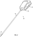
- FIG. 2 is an isometric top view of an example surgical tool 200 that may incorporate some or all of the principles of the present disclosure.
- the surgical tool 200 may be the same as or similar to the surgical instrument(s) 108 of FIG. 1 and, therefore, may be used in conjunction with the robotic surgical system 100 of FIG. 1 .
- the surgical tool 200 may be designed to be releasably coupled to a robotic arm 106 ( FIG. 1 ) of a robotic manipulator of the robotic surgical system 100.
- Full detail and operational description of the surgical tool 200 is provided in U.S. Patent Pub. 2016/0287252 , entitled "Clip Applier Adapted for Use with a Surgical Robot," the contents of which are hereby incorporated by reference in their entirety.
- the surgical tool 200 can include an elongate shaft 202, an end effector 204 coupled to the distal end of the shaft 202, and a drive housing 206 coupled to the proximal end of the shaft 202.
- proximal and distal are defined herein relative to a robotic surgical system having an interface configured to mechanically and electrically couple the surgical tool 200 (e.g., the drive housing 206) to a robotic manipulator.
- proximal refers to the position of an element closer to the robotic manipulator and the term “distal” refers to the position of an element closer to the end effector 204 and thus further away from the robotic manipulator.
- the drive housing 206 can include a tool mounting portion 208 designed with features that releasably couple the surgical tool 200 to a robotic arm (e.g., the robotic arms 106 or "tool drivers" of FIG. 1 ) of a robotic manipulator.
- the tool mounting portion 208 may releasably attach (couple) the drive housing 206 to a tool driver in a variety of ways, such as by clamping thereto, clipping thereto, or slidably mating therewith.
- the tool mounting portion 208 may include an array of electrical connecting pins, which may be coupled to an electrical connection on the mounting surface of the tool driver. While the tool mounting portion 208 is described herein with reference to mechanical, electrical, and magnetic coupling elements, it should be understood that a wide variety of telemetry modalities might be used, including infrared, inductive coupling, or the like.
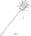
- FIG. 3 is an isometric bottom view of the surgical tool 200.
- the surgical tool 200 further includes an interface 302 that mechanically and electrically couples the tool mounting portion 208 to a robotic manipulator.
- the tool mounting portion 208 includes a tool mounting plate 304 that operably supports a plurality of drive inputs, shown as a first drive input 306a, a second drive input 306b, and a third drive input 306c. While only three drive inputs 306a-c are shown in FIG. 3 , more or less than three may be employed, without departing from the scope of the disclosure.
- each drive input 306a-c comprises a rotatable disc configured to align with and couple to a corresponding input actuator (not shown) of a given tool driver. Moreover, each drive input 306a-c provides or defines one or more surface features 308 configured to align with mating surface features provided on the corresponding input actuator.
- the surface features 308 can include, for example, various protrusions and/or indentations that facilitate a mating engagement.
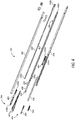
- FIG. 4 is an exploded view of one example of the elongate shaft 202 and the end effector 204 of the surgical tool 200 of FIGS. 2 and 3 , according to one or more embodiments.
- the shaft 202 includes an outer tube 402 that houses the various components of the shaft 202, which can include a jaw retaining assembly 404.
- the jaw retaining assembly 404 includes a jaw retainer shaft 406 with a clip track 408 and a push rod channel 410 formed thereon.
- the end effector 204 includes opposing jaws 412 that are configured to mate to a distal end of the clip track 408.
- the shaft 202 also includes a clip advancing assembly, which, in one example embodiment, can include a feeder shoe 414 adapted to be slidably disposed within the clip track 408.
- the feeder shoe 414 is designed to advance a series of clips 416 positioned within the clip track 408, and a feedbar 418 is adapted to drive the feeder shoe 414 through the clip track 408.
- An advancer assembly 420 is adapted to mate to a distal end of the feedbar 418 for advancing a distal-most clip into the jaws 412.
- the shaft 202 furthers include a clip forming or camming assembly operable to collapse the jaws 412 and thereby crimp (crush) a surgical clip 416 positioned between (interposing) the jaws 412.
- the camming assembly includes a cam 422 that slidably mates to the jaws 412, and a push rod 424 that moves the cam 422 relative to the jaws 412 to collapse the jaws 412.
- a tissue stop 426 can mate to a distal end of the clip track 408 to help position the jaws 412 relative to a surgical site.
- the jaw retainer shaft 406 is extendable within and couples to the outer tube 402 at a proximal end 428a, and its distal end 428b is adapted to mate with the jaws 412.
- the push rod channel 410 formed on the jaw retainer shaft 406 may be configured to slidably receive the push rod 424, which is used to advance the cam 422 over the jaws 412.
- the clip track 408 extends distally beyond the distal end 428b of the jaw retainer shaft 406 to allow a distal end of the clip track 408 to be substantially aligned with the jaws 412.
- the clip track 408 can include several openings 430 formed therein for receiving an upper or "superior” tang 432a formed on the feeder shoe 414 adapted to be disposed within the clip track 408.
- the clip track 408 can also include a stop tang 434 formed thereon that is effective to be engaged by a corresponding stop tang formed on the feeder shoe 414 to prevent movement of the feeder shoe 414 beyond a distal-most position.
- the feeder shoe 414 can also include a lower or "inferior" tang 432b formed on the underside thereof for allowing the feeder shoe 414 to be engaged by the feedbar 418 as the feedbar 418 is moved distally.
- each time the feedbar 418 is moved distally a detent formed in the feedbar 418 engages the inferior tang 432b and moves the feeder shoe 414 distally a predetermined distance within the clip track 408.
- the feedbar 418 can then be moved proximally to return to its initial position, and the angle of the inferior tang 432b allows the inferior tang 432b to slide into the next detent formed in the feedbar 418.
- the jaws 412 include first and second opposed jaw members that are movable (collapsible) relative to one another and are configured to receive a surgical clip from the series of clips 416 therebetween.
- the jaw members can each include a groove formed on opposed inner surfaces thereof for receiving the legs of a surgical clip 416 in alignment with the jaw members.
- the jaw members are biased to an open position and a force is required to urge the jaw members toward one another to crimp the interposing clip 416.
- the jaw members can also each include a cam track formed thereon for allowing the cam 422 to slidably engage and move the jaw members toward one another.
- a proximal end 436a of the cam 422 is matable with a distal end 438a of the push rod 424, and a distal end 436b of the cam 422 is adapted to engage and actuate the jaws 412.
- the proximal end 438b of the push rod 424 is matable with a closure link assembly associated with the drive housing 206 for moving the push rod 424 and the cam 422 relative to the jaws 412.
- the distal end 436b of the cam 422 includes a camming channel or tapering recess formed therein for slidably receiving corresponding cam tracks provided by the jaw members.
- the cam 422 is advanced from a proximal position, in which the jaw members are spaced apart from one another, to a distal position, where the jaw members are collapsed to a closed position.
- the tapering recess at the distal end 436b serves to push the jaw members toward one another, thereby crimping a surgical clip 416 disposed therebetween.
- FIG. 5 is an exposed isometric view of the surgical tool 200 of FIG. 2 , according to one or more embodiments.
- the shroud or covering of the drive housing 206 has been removed to reveal the internal component parts.
- the surgical tool 200 may include a first drive gear 502a, a second drive gear 502b, and a third drive gear 502c.
- the first drive gear 502a may be operatively coupled to (or extend from) the first drive input 306a ( FIG. 3 ) such that actuation of the first drive input 306a correspondingly rotates the first drive gear 502a.
- the second and third drive gears 502b,c may be operatively coupled to (or extend from) the second and third drive inputs 306b,c ( FIG. 3 ), respectively, such that actuation of the second and third drive inputs 306b,c correspondingly rotates the second and third drive gears 502b,c, respectively.
- the first drive gear 502a may be configured to intermesh with a first driven gear 504a, which is operatively coupled to the shaft 202.
- the driven gear 504a comprises a helical gear. In operation, rotation of the first drive gear 502a about a first axis correspondingly rotates the first driven gear 504a about a second axis orthogonal to the first axis to control rotation of the shaft 202 in clockwise and counter-clockwise directions based on the rotational direction of the first drive gear 502a.
- the second drive gear 502b may be configured to intermesh with a second driven gear 504b (partially visible in FIG. 5 ), and the third drive gear 502c may be configured to intermesh with a third driven gear 504c.
- the second and third drive and driven gears 502b,c, 504b,c comprise corresponding rack and pinion interfaces, where the driven gears 504b,c comprise the rack and the drive gears 502b,c comprise the pinion.
- Independent rotation of the second and third drive gears 502b,c will cause the second and third driven gears 504b,c, respectively, to translate linearly relative to (independent of) one another.
- actuation (rotation) of the third drive gear 502c will result in a surgical clip 416 ( FIG. 4 ) being fed into the jaws 412.
- the third driven gear 504c may be operatively coupled to the feedbar 418 ( FIG. 4 ) and, upon rotation of the third drive gear 502c in a first angular direction, the third driven gear 504c will advance distally and correspondingly advance the feedbar 418 a sufficient distance to fully advance a surgical clip into the jaws 412.
- Rotation of the third drive gear 502c may be precisely controlled by an electrical and software interface to deliver the exact linear travel to the third driven gear 504c necessary to feed a clip 416 into the jaws 412.
- Actuation of the second drive gear 502b causes the jaws 412 to close or collapse to crimp a surgical clip.
- the second driven gear 504b may be coupled to the proximal end 438b ( FIG. 4 ) of the push rod 424 ( FIG. 4 ) and, upon actuation of the second drive gear 502b in a first angular direction, the second driven gear 504b will be advanced linearly in a distal direction and correspondingly drive the push rod 424 distally, which drives the cam 422 over the jaws 412 to collapse the jaw members and crimp a surgical clip positioned in the jaws 412.
- the processes of delivering a surgical clip into the jaws 412 and collapsing the jaws 412 to crimp the surgical clip are not limited to the actuation mechanisms and structures described herein.
- the second and third driven gears 504b,c may instead comprise capstan pulleys configured to route and translate drive cables within the shaft 202.
- the drive cables may be operatively coupled to one or more lead screws or other types of rotating members positioned within the shaft 202 near the distal end and capable of advancing the feedbar 418 to deliver a surgical clip into the jaws 412 and advancing the cam 422 to collapse the jaws 412 and crimp the surgical clip.
- FIG. 6 is an isometric top view of another example surgical tool 600 that may incorporate some or all of the principles of the present disclosure. Similar to the surgical tool 200 of FIG. 2 , the surgical tool 600 may be used in conjunction with the robotic surgical system 100 of FIG. 1 . As illustrated, the surgical tool 600 includes an elongate shaft 602, an end effector 604 positioned at the distal end of the shaft 602, a wrist 606 (alternately referred to as a "articulable wrist joint") that couples the end effector 604 to the distal end of the shaft 602, and a drive housing 608 coupled to the proximal end of the shaft 602. In some embodiments, the shaft 602, and hence the end effector 604 coupled thereto, is configured to rotate about a longitudinal axis A 1 .
- the end effector 604 comprises a clip applier that includes opposing jaw members 610, 612 configured to collapse toward one another to crimp a surgical clip.
- the wrist 606 comprises an articulatable joint that facilitates pivoting movement of the end effector 604 relative to the shaft 602 to position the end effector 604 at desired orientations and locations relative to a surgical site.
- the housing 608 includes (contains) various actuation mechanisms designed to control articulation and operation of the end effector 604.
- FIG. 7 illustrates the potential degrees of freedom in which the wrist 606 may be able to articulate (pivot).
- the degrees of freedom of the wrist 606 are represented by three translational variables (i.e., surge, heave, and sway), and by three rotational variables (i.e., Euler angles or roll, pitch, and yaw).
- the translational and rotational variables describe the position and orientation of a component of a surgical system (e.g., the end effector 604) with respect to a given reference Cartesian frame.
- surge refers to forward and backward translational movement
- heave refers to translational movement up and down
- sway refers to translational movement left and right.
- rotational terms “roll” refers to tilting side to side, “pitch” refers to tilting forward and backward, and “yaw” refers to turning left and right.
- the pivoting motion can include pitch movement about a first axis of the wrist 606 (e.g., X-axis), yaw movement about a second axis of the wrist 606 (e.g., Y-axis), and combinations thereof to allow for 360° rotational movement of the end effector 604 about the wrist 606.
- the pivoting motion can be limited to movement in a single plane, e.g., only pitch movement about the first axis of the wrist 606 or only yaw movement about the second axis of the wrist 606, such that the end effector 604 moves only in a single plane.
- the surgical tool 600 includes a plurality of drive cables (generally obscured in FIG. 6 ) that form part of a cable driven motion system configured to facilitate operation and articulation (movement) of the end effector 604 relative to the shaft 602.
- a cable driven motion system configured to facilitate operation and articulation (movement) of the end effector 604 relative to the shaft 602.
- selectively moving the drive cables can actuate the end effector 604 and thereby collapse the jaw members 610, 612 toward each other.
- moving the drive cables can also move the end effector 604 between an unarticulated position and an articulated position.
- the end effector 604 is depicted in FIG.
- FIG. 8 is an enlarged isometric view of the distal end of the surgical tool 600 of FIG. 6 . More specifically, FIG. 8 depicts an enlarged and partially exploded view of the end effector 604 and the wrist 606.
- the wrist 606 operatively couples the end effector 604 to the shaft 602.
- the wrist 606 includes a distal clevis 802a, a proximal clevis 802b, and a spacer 803 interposing the distal and proximal clevises 802a,b.
- the end effector 604 is coupled to the distal clevis 802a and the distal clevis 802a is rotatably mounted to the spacer 803 at a first axle 804a.
- the spacer 803 is rotatably mounted to the proximal clevis 802b at a second axle 804b and the proximal clevis 802b is coupled to a distal end 806 of the shaft 602.
- the wrist 606 provides a first pivot axis P 1 that extends through the first axle 804a and a second pivot axis P 2 that extends through the second axle 804b.
- the first pivot axis P 1 is substantially perpendicular (orthogonal) to the longitudinal axis A 2 of the end effector 604, and the second pivot axis P 2 is substantially perpendicular (orthogonal) to both the longitudinal axis A 2 and the first pivot axis P 1 . Movement about the first pivot axis P 1 provides "pitch" articulation of the end effector 604, and movement about the second pivot axis P 2 provides "yaw” articulation of the end effector 604.
- a plurality of drive cables 808 extend longitudinally within the shaft 602 and pass through the wrist 106 to be operatively coupled to the end effector 604.
- the drive cables 808 form part of the cable driven motion system briefly described above, and may be referred to and otherwise characterized as cables, bands, lines, cords, wires, ropes, strings, twisted strings, elongate members, etc.
- the drive cables 808 can be made from a variety of materials including, but not limited to, metal (e.g., tungsten, stainless steel, etc.) or a polymer.
- the drive cables 808 extend proximally from the end effector 604 to the drive housing 608 ( FIG. 6 ) where they are operatively coupled to various actuation mechanisms or devices housed (contained) therein to facilitate longitudinal movement (translation) of the drive cables 808.
- Selective actuation of the drive cables 808 causes the end effector 604 to articulate (pivot) relative to the shaft 602.
- Moving a given drive cable 808 constitutes applying tension (i.e., pull force) to the given drive cable 808 in a proximal direction, which causes the given drive cable 808 to translate and thereby cause the end effector 604 to move (articulate) relative to the shaft 602.
- One or more actuation cables 810 may also extend longitudinally within the shaft 602 and pass through the wrist 106 to be operatively coupled to the end effector 604.
- the actuation cables 810a,b may be similar to the drive cables 808 and also form part of the cable driven motion system. Selectively actuating the actuation cables 810a,b causes the end effector 604 to actuate, such as collapsing the first and second jaw members 610, 612 to crimp a surgical clip (not shown).
- the actuation cables 810a,b may be operatively coupled to a cam 812 that is slidably engageable with the jaw members 610, 612.
- One or more pulleys 814 may be used to receive and redirect the first actuation cables 810a for engagement with the cam 812. Longitudinal movement of the first actuation cables 810a correspondingly moves the cam 812 distally relative to the jaw members 610, 612.
- the distal end of the cam 812 includes a tapering recess or camming channel 816 formed therein for slidably receiving corresponding cam tracks 818 provided by the jaw members 610, 612.
- the camming channel 816 pushes (collapses) the jaw members 610, 612 toward one another, thereby crimping a surgical clip (not shown) disposed therebetween.
- Actuation of the second actuation cables 810b pulls the cam 812 proximally, thereby allowing the jaw members 610, 612 to open again to receive another surgical clip.
- an assembly including, for example, a feedbar, a feeder shoe, and a clip track may be included at or near the end effector 604 to facilitate feeding surgical clips into the jaw members 610, 612.
- the feedbar (or a connecting member) may be flexible and extend through the wrist 606.
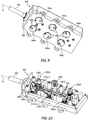
- FIG. 9 is a bottom view of the drive housing 608, according to one or more embodiments.
- the drive housing 608 may include a tool mounting interface 902 used to operatively couple the drive housing 608 to a tool driver of a robotic manipulator.
- the tool mounting interface 902 may mechanically, magnetically, and/or electrically couple the drive housing 608 to a tool driver.
- the interface 902 includes and supports a plurality of drive inputs, shown as drive inputs 906a, 906b, 906c, 906d, 906e, and 906f.
- Each drive input 906a-f may comprise a rotatable disc configured to align with and couple to a corresponding input actuator (not shown) of a tool driver.
- each drive input 906a-f provides or defines one or more surface features 908 configured to align with mating features provided on the corresponding input actuator.
- the surface features 908 can include, for example, various protrusions and/or indentations that facilitate a mating engagement.
- actuation of the first drive input 906a may control rotation of the elongate shaft 602 about its longitudinal axis A 1 . Depending on the rotational actuation of the first drive input 906a, the elongate shaft 602 may be rotated clockwise or counter-clockwise.
- selective actuation of the second and third drive inputs 906b,c may cause movement (axial translation) of the actuation cables 810a,b ( FIG. 8 ), which causes the cam 812 ( FIG. 8 ) to move and crimp a surgical clip, as generally described above.
- actuation of the fourth drive input 906d feeds a surgical clip into the jaw members 610, 612 ( FIG. 8 ).
- actuation of the fifth and sixth drive inputs 906e,f causes movement (axial translation) of the drive cables 808 ( FIG. 8 ), which results in articulation of the end effector 604.
- Each of the drive inputs 906a-f may be actuated based on user inputs communicated to a tool driver coupled to the interface 902, and the user inputs may be received via a computer system incorporated into the robotic surgical system.
- FIG. 10 is an isometric exposed view of the interior of the drive housing 608, according to one or more embodiments. Several component parts that may otherwise be contained within the drive housing 608 are not shown in FIG. 10 to enable discussion of the depicted component parts.
- the drive housing 608 contains a first capstan 1002a, which is operatively coupled to or extends from the first drive input 906a ( FIG. 9 ) such that actuation of the first drive input 906a results in rotation of the first capstan 1002a.
- a helical drive gear 1004 is coupled to or forms part of the first capstan 1002a and is configured to mesh and interact with a driven gear 1006 operatively coupled to the shaft 602 such that rotation of the driven gear 1006 correspondingly rotates the shaft 602. Accordingly, rotation of the helical drive gear 1004 (via actuation of the first drive input 906a of FIG. 9 ) will drive the driven gear 1006 and thereby control rotation of the elongate shaft 602 about the longitudinal axis A 1 .
- the drive housing 608 also includes second and third capstans 1002b and 1002c operatively coupled to or extending from the second and third drive inputs 906b,c ( FIG. 9 ), respectively, such that actuation of the second and third drive inputs 906b,c results in rotation of the second and third capstans 1002b,c.
- the second and third capstans 1002b,c comprise capstan pulleys operatively coupled to the actuation cables 810a,b ( FIG. 8 ) such that rotation of a given capstan 1002b,c actuates (longitudinally moves) a corresponding one of the actuation cables 810a,b.
- the drive housing 608 further includes a fourth capstan 1002d, which is operatively coupled to or extends from the fourth drive input 906d ( FIG. 9 ) such that actuation of the fourth drive input 906d results in rotation of the fourth capstan 1002d.
- a spur gear 1008 is coupled to or forms part of the fourth capstan 1002d and is configured to mesh and interact with a rack gear (not shown) also contained within the drive housing 608.
- the rack gear may be operatively coupled to a feedbar (or another connecting member) which facilitates operation of a feeder shoe and associated clip track to feed surgical clips into the jaw members 610, 612 ( FIGS. 6 and 8 ). Accordingly, rotation of the spur gear 1008 (via actuation of the fourth drive input 906d) will control the feedbar and thereby control loading of surgical clips into the jaw members 610, 612 as desired.
- the drive housing 608 further contains or houses fifth and sixth capstans 1002e and 1002f operatively coupled to or extending from the fifth and sixth drive inputs 906e,f ( FIG. 9 ), respectively, such that actuation of the fifth and sixth drive inputs 906e,f results in rotation of the fifth and sixth capstans 1002e,f.
- the fifth and sixth capstans 1002e,f comprise capstan pulleys operatively coupled to the drive cables 808 ( FIG. 8 ) such that rotation of a given capstan 1002e,f actuates (longitudinally moves) a corresponding one of the actuation cables 808.
- the surgical tools 200, 600 described herein above may incorporate and facilitate the principles of the present disclosure in improving feeding and/or forming of surgical clips in robotic clip appliers. Moreover, it is contemplated herein to combine some or all of the features of the surgical tools 200, 600 to facilitate operation of the embodiments described herein. Accordingly, example surgical tools that may incorporate the principles of the present disclosure may include geared actuators, capstan pulley and cable actuators, or any combination thereof, without departing from the scope of the disclosure.
- FIG. 11 is an enlarged isometric view of an example end effector 1102, according to one or more embodiments the present disclosure.
- the end effector 1102 may be similar in some respects to the end effectors 204 and 604 of FIGS. 2 and 6 , respectively. Similar to the end effectors 204, 604, for example, the end effector 1102 may be incorporated into either or both of the surgical tools 200, 600 described herein above.
- the end effector 1102 may comprise a clip applier having opposed jaw members 1104 and 1106 configured to collapse toward one another to crimp a surgical clip.
- the end effector 1102 may incorporate various component parts and actuatable mechanisms or features that facilitate the feeding of a surgical clip into the jaw members 1104, 1106 and collapsing the jaw members 1104, 1106 to crimp the surgical clip when desired.
- the end effector 1102 includes an elongate body 1108 having a proximal end 1110a and a distal end 1110b.
- the proximal end 1110a may be operatively coupled to an elongate shaft of a surgical tool, such as the shaft 202 of the surgical tool 200 of FIG. 2 .
- the proximal end 1110a may be operatively coupled to an articulable wrist joint, such as the wrist 606 of the surgical tool 600 of FIG. 6 .
- the end effector 1102 includes a head 1112 positioned or otherwise included at the distal end 1110b of body 1108.
- the head 1112 may be rotatably coupled to the body 1108 at a hinge or axle 1114, and the jaw members 1104, 1106 may be incorporated into or otherwise form part of the head 1112 such that rotation of the head 1112 on the axle 1114 correspondingly moves the jaw members 1104, 1106 in the same angular direction.
- a pivot axis P 1 extends through the axle 1114 and is substantially perpendicular to a longitudinal axis A 1 of the effector 1102.
- the head 1112 may be pivotable about the pivot axis P 1 between a loading position, where the jaw members 1104, 1106 are positioned to receive a surgical clip, and a clamping position, where the jaw members 1104, 1106 are positioned and otherwise poised to clamp (crimp) a surgical clip at a desired location.
- the clamping position may be any angular position away from the loading position and relative to the longitudinal axis A 1 of the effector 1102 where the jaw members 1104, 1106 are able to properly crimp a surgical clip at a desired location.
- a surgical clip at any angular location as long as it does not interfere with clip loading at the loading position.
- one advantage of the angular versatility of the head 1112 is that a user may be able to position the jaw members 1104, 1106 in a reverse position (i.e., retroflexion and/or retroflex articulation) relative to target tissue, which increases the maneuverability.
- the range of potential angular movement of the head 1112 may be about 180o.
- the clamping position may comprise any angle between the loading position and 180o from the loading position. In practice, however, and to account for the loading position, the clamping position may comprise any angle between 0o and about 160o relative to the longitudinal axis A 1 . In other embodiments, however, the range of potential angular movement of the head 1112 may be 360o. In such embodiments, the head 1112 may be capable of pivoting through the loading position in either angular direction and the clamping position may comprise virtually any angle relative to the longitudinal axis A 1 .
- the clamping position may comprise any angle between 0o and about 160o in in either angular direction relative to the longitudinal axis A 1 .
- the end effector 1102 further includes a clip cartridge 1116 coupled to the body 1108 proximal to the head 1112 and configured to house one or more surgical clips 1118 (one partially shown).
- the clip cartridge 1116 may be removably coupled to the body 1108, such as through the use of one or more mechanical fasteners (e.g., screws), an interference fit, a snap fit, any combination thereof, or the like.
- the clip cartridge 1116 may be removed from the body 1108 when the supply of surgical clips 1118 is exhausted.
- the clip cartridge 1116 may then either be replaced with a new cartridge containing additional surgical clips, or additional surgical clips 1118 may be added to the clip cartridge 1116, which may then be reattached to the body 1108 for further operation.
- the clip cartridge 1116 may form an integral part of the body 1108. In such embodiments, when the supply of surgical clips 1118 is exhausted the end effector 1102 may be replaced with a new end effector having a fresh supply of surgical clips.
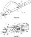
- FIGS. 12A-12D depict progressive isometric views of the end effector 1102 during an example clip loading operation, according to one or more embodiments of the disclosure.
- the head 1112 is shown in the process of being moved or rotated (pivoted) about the pivot axis P 1 toward the loading position where the jaw members 1104, 1106 become aligned or substantially aligned with a distal-most surgical clip 1118 to be received by the jaw members 1104, 1106.
- the distal-most surgical clip 1118 may be one of a plurality of surgical clips 1118 contained within the clip cartridge 1116, or may alternatively be the only or last surgical clip 1118 contained within the clip cartridge 1116.
- the means for actuating the head 1112 between the clamping and loading positions will be discussed in further detail below.
- the clip cartridge 1116 may define an opening 1202 through which the surgical clips 1118 are discharged to be received by the jaw members 1104, 1106.
- the crown of the distal-most surgical clip 1118 may protrude a short distance through the opening 1202 prior to being discharged from the clip cartridge 1116.
- the opening 1202 may be slightly smaller than the dimensions of the surgical clip 1118 to prevent the surgical clip 1118 from prematurely or inadvertently advancing out of the clip cartridge 1116.
- the distal-most surgical clip 1118 may be contained wholly within the clip cartridge 1116 prior to being discharged from the clip cartridge 1116 via the opening 1202.
- each jaw member 1104, 1106 can include a channel or groove 1206 (better seen in FIG. 13A ) formed on opposed inner surfaces thereof for receiving the distal-most surgical clip 1118.
- the grooves 1206 may prove advantageous in helping to capture and maintain the surgical clip 1118 in a known position between the jaw members 1104, 1106.
- the grooves 1206 may be omitted and the distal-most surgical clip 1118 may instead be captured or held by the jaw members 1104, 1106 via an interference fit or the like.
- the end effector 1102 may include a hard stop 1208 configured to receive and stop pivoting motion of the head 1112 at the loading position.
- the body 1108 of the end effector 1102 may provide or define the hard stop 1208, but the hard stop 1208 may alternatively be a structure coupled to the body 1108.
- the hard stop 1208 may prove advantageous in helping maintain consistent loading alignment for the surgical clips 1118.
- the hard stop 1208 may be omitted and the actuation mechanisms that facilitate pivoting movement of the head 1112 may be configured to precisely align the jaw members 1104, 1106 with the distal-most surgical clip 1118.
- the clip cartridge 1116 is depicted in FIG. 12B in phantom and thereby exposing a set 1204 of surgical clips 1118 that might be contained within the clip cartridge 1116. While seven surgical clips 1118 are shown in the set 1204, it will be appreciated that more or less than seven may be contained within the clip cartridge 1116, without departing from the scope of the disclosure. Indeed, in at least one embodiment, the set 1204 may comprise a single surgical clip 1118.
- Each surgical clip 1118 includes a crown 1210 (alternately referred to as an "apex") and a pair of legs 1212 extending longitudinally from the crown 1210. As illustrated, the surgical clips 1118 are positioned end-to-end within the clip cartridge 1116 with the legs 1212 of the more distal surgical clips 1118 resting on the crown 1210 of the more proximal surgical clips 1118. Accordingly, the surgical clips 1118 are arranged within the clip cartridge 1116 with the crown 1210 leading and the legs 1212 extending proximally therefrom. As a result, the surgical clips 1118 are fed crown 1210 first into the jaw members 1104, 1106. In contrast, conventional robotic clip appliers typically feed surgical clips legs first into opposed jaw members.
- Surgical clips are commonly designed to exhibit a slight taper, where the angle of the legs 1212 extending from the crown 1210 converge. This helps facilitate wedging the clips into the jaws legs first.
- One disadvantage of this clip design is that it reduces the clip-to-jaw retention capability since the legs are more tapered than the jaw. This also reduces allowable tip width between the jaw members, which correspondingly limits the size of tissue that can be treated.
- Feeding the surgical clips 1118 crown first 1210 into the jaw members 1104, 1106 advantageously helps mitigate the surgical clips 1118 from getting caught on any sharp corners or the like that might obstruct their distal advancement.
- the legs 1212 may spring outward and seat themselves within the grooves 1206 after having exited the clip cartridge 1116 by bypassing the smaller-sized opening 1202.
- feeding the surgical clips 1118 crown first 1210 into the jaw members 1104, 1106 allows a clip design where the legs 1212 can diverge, which increases clip to jaw retention and maximizes the allowable tip width between the jaw members 1104, 1106, and thereby increasing the size of tissue that can be treated.
- the distal-most surgical clip 1118 has been advanced distally out of the clip cartridge 1116 and received by the jaw members 1104, 1106.
- the penultimate surgical clip 1118 may correspondingly advance distally until its crown 1210 protrudes a short distance out of the opening 1202. In other embodiments, however, the penultimate surgical clip 1118 may remain entirely contained within the clip cartridge 1116 when the distal-most surgical clip 1118 has been received by the jaw members 1104, 1106, without departing from the scope of the disclosure.
- Advancing the set 1204 of surgical clips 1118 distally to discharge the distal-most surgical clip 1118 from the clip cartridge 1116 may be accomplished by actuating (moving) a clip pusher 1210.
- the clip pusher 1210 may comprise any type of structure capable of applying an axial load on the set 1204 and thereby moving the set 1204 distally.
- the clip pusher 1210 may comprise any rigid or semi-rigid rod, shaft, or planar structure (e.g., an elongate strip-like structure), or any combination thereof.
- the clip pusher 1210 comprises a type of planar pusher bar, but could alternatively comprise another rigid or semi-rigid structure.
- the clip pusher 1210 is depicted herein as merely one example, and those skilled in the art will readily appreciate that many different configurations of the clip pusher 1210 may be employed, without departing from the scope of the disclosure.
- the clip pusher 1210 is depicted as being in contact with the legs 1212 of the proximal-most surgical clip 1118. Because of the end-to-end arrangement of the surgical clips 1118, pushing the proximal-most surgical clip 1118 will correspondingly move the remaining surgical clips 1118 in the set 1204 in the same direction. In other embodiments, however, the clip pusher 1210 may be configured to engage any other portion of the proximal-most surgical clip 1118. In yet other embodiments, the clip pusher 1210 may be configured to engage a combination of two or more surgical clips 1118 to apply the required axial load on the set 1204 to move the set 1204 distally, without departing from the scope of the disclosure.
- the clip pusher 1210 may apply an axial load on the surgical clips 1118 sufficient to advance the set 1204 distally and discharge the distal-most surgical clip 1118 from the clip cartridge 1116 via the opening 1202.
- actuation and distal movement of the clip pusher 1210 may be precisely controlled to deliver the exact amount of force and linear travel necessary to push (force) the distal-most surgical clip 1118 through the smaller-sized opening 1202 and feed the distal-most surgical clip 1118 into the jaw members 1104, 1106.
- the clip pusher 1210 may extend proximally to a drive housing (e.g., the drive housings 206, 606 of FIGS. 2 and 6 , respectively), which may include a drive input and corresponding actuating mechanisms configured to actuate (move) the clip pusher 1210 as needed.
- the clip pusher 1210 may be operatively coupled to or otherwise form part of a clip feeding assembly including, for example, a flexible or rigid feedbar (e.g., the feedbar 418 of FIG. 4 ) that extends from the drive housing and is actuated to correspondingly move the clip pusher 1210 distally and proximally as desired.
- the head 1112 is shown as having moved (pivoted) away from the loading position to a clamping position.
- the clamping position for the head 1112 may be any angular position away from the loading position and relative to or aligned with the longitudinal axis A 1 .
- the head 1112 is depicted as being aligned or substantially aligned with the longitudinal axis A 1 , but could alternatively be angularly offset from the longitudinal axis A 1 .
- the surgical clip 1118 received within the jaw members 1104, 1106 is now ready to be deployed to ligate desired body tissue, for example, a blood vessel, a duct, a shunt, etc.
- desired body tissue for example, a blood vessel, a duct, a shunt, etc.
- the end effector 1102 may further include one or more proximity sensors 1214 (one shown) configured to sense and/or detect adjacent body structures or tissue during operation.
- the proximity sensor 1214 is depicted as being coupled to or positioned on the head 1112, but might alternatively be positioned at other locations on the end effector 1102. The sensor 1214 may prove advantageous in helping determine when the head 1112 may safely pivot between the clamping and loading positions without coming into contact or otherwise damaging sensitive body structures or tissue.
- the sensor 1214 may be communicably coupled (wired or wirelessly) to a robotic controller (e.g., controllers 102a,b of FIG. 1 ) operated by a user, and the user may be updated in real-time as to the position of the head 1112 relative to sensitive body tissue.
- a robotic controller e.g., controllers 102a,b of FIG. 1
- the real-time updates will help the user safely pivot the head 1112 without contacting anything vital or obstructing its movement.
- FIGS. 13A and 13B are exposed, partial cross-sectional side views of the end effector 1102, according to one or more embodiments. More specifically, FIG. 13A depicts the end effector 1102 prior to crimping a surgical clip 1118 between the jaw members 1104, 1106, and FIG. 13B shows the end effector 1102 following actuation to collapse the jaw members 1104, 1106.
- the end effector 1102 includes a rotational actuator 1302a operable to move (pivot) the head 1112 between the loading and clamping positions, and further includes a linear actuator 1302b operable to actuate the jaw members 1104, 1106 to crimp the surgical clip 1118.
- the rotational actuator 1302a may comprise any device or mechanism capable of or configured to pivot the head 1112 between the loading position and any clamping position.
- the rotational actuator 1302a includes an articulation pulley 1304 mounted to the axle 1114 such that rotation of the articulation pulley 1304 correspondingly rotates the axle 1114.
- a first drive cable 1306a may be routed around the articulation pulley 1304 to cause rotation of the articulation pulley 1304 when translated longitudinally. Since the head 1112 is operatively coupled to the axle 1114, rotation of the articulation pulley 1304, as acted upon by the first drive cable 1306a, simultaneously causes the head 1112 to rotate in the same angular direction.
- the first drive cable 1306a may be similar to the drive cables 808 of FIG. 8 . Moreover, the first drive cable 1306a may extend from a drive housing (e.g., the drive housings 206, 606 of FIGS. 2 and 6 , respectively) and may be operatively coupled to a corresponding actuating mechanism or device positioned within the drive housing and configured to cause longitudinal translation of the first drive cable 1306a. In one embodiment, for example, the first drive cable 1306a may be operatively coupled to one or more capstan pulleys, such as any of the rotatable capstans 1002a-f of FIG. 10 .
- first drive cable 1306a may be operatively coupled and otherwise extend from one or more translatable driven gears, such as the first and second driven gears 504a,b of FIG. 5 .
- first drive cable 1306a may be operatively coupled to any combination of capstan pulley and driven gear, without departing from the scope of the disclosure.
- the linear actuator 1302b may comprise any device or mechanism capable of or configured to move (collapse) the jaw members 1104, 1106 toward each other and thereby crimp the surgical clip 1118 disposed therebetween.
- the linear actuator 1302b includes a jaw pulley 1308, a bevel gear assembly 1310 operatively coupled to the jaw pulley 1308, and a threaded linear drive 1312 operatively coupled to the bevel gear assembly 1310. Rotation of the jaw pulley 1308 may cause actuation of the bevel gear assembly 1310, which, in turn, may cause actuation of the threaded linear drive 1312, which operates to collapse and open the jaw members 1104, 1106.
- the jaw pulley 1308 may be rotatably mounted to the axle 1114, but loosely mounted such that rotation of the jaw pulley 1308 does not rotate or otherwise act on the axle 1114.
- a second drive cable 1306b may be routed around the jaw pulley 1308 to cause rotation of the jaw pulley 1308. Similar to the first drive cable 1306a, the second drive cable 1306b may be similar to the drive cables 808 of FIG. 8 and may extend from a drive housing (e.g., the drive housings 206, 606 of FIGS. 2 and 6 , respectively) where it is operatively coupled to a corresponding actuating mechanism or device configured to cause longitudinal translation of the second drive cable 1306b.
- a drive housing e.g., the drive housings 206, 606 of FIGS. 2 and 6 , respectively
- the bevel gear assembly 1310 may include a beveled drive gear 1314a coupled to or forming part of the jaw pulley 1308 and a corresponding beveled driven gear 1314b positioned to be driven (rotated) by the drive gear 1314a.
- the threaded linear drive 1312 may include a worm gear 1316 operatively coupled to or extending from the driven gear 1314b, and a threaded gear plate 1318 that provides a female threading 1320 configured to threadably mate with or engage the helical threading defined on the worm gear 1316.
- Example operation of the rotational actuator 1302a and the linear actuator 1302b is now provided.
- the first drive cable 1306a may be translated (moved) in either longitudinal direction. Movement of the first drive cable 1306a rotates the articulation pulley 1304, which correspondingly rotates the axle 1114 about the pivot axis P 1 . Since the head 1112 is operatively coupled to the axle 1114, rotation of the axle 1114 will simultaneously cause the head 1112 to rotate in the same angular direction.
- the longitudinal movement of the first drive cable 1306a may be precisely controlled to place the jaw members 1104, 1106 in the loading position and to otherwise accurately align the jaw members 1104, 1106 with a distal-most surgical clip for loading. Likewise, longitudinal movement of the first drive cable 1306a may be precisely controlled to position or otherwise orient the head 1112 in a desired clamping position away from the loading position.
- the second drive cable 1306b may be translated (moved) in a first driving direction, as indicated by the arrows A ( FIG. 13B ).
- the jaw pulley 1308 and the drive gear 1314a are correspondingly rotated relative to the axle 1114, and the drive gear 1314a transmits a rotational load to the driven gear 1314b, which correspondingly rotates in a first angular direction, as indicated by the arrow B ( FIG. 13B ).
- the jaw members 1104, 1106 comprise independent or separate plate-like structures that are configured to move laterally relative to one another to collapse and crimp the surgical clip 1118.
- Each jaw member 1104, 1106 may provide and otherwise define one or more angled slots 1322 that extend at an angle offset from the longitudinal axis A 1 of the end effector 1102. While two angled slots 1322 are shown on each jaw member 1104, 1106, it will be appreciated that more or less than two may be employed, without departing from the scope of the disclosure.
- the angled slots 1322 of each jaw member 1104, 1106 may extend at equal but opposite angles.
- the slots 1322 of the first jaw member 1104 may extend at a positive angle relative to the longitudinal axis A 1
- the slots 1322 of the second jaw member 1106 may extend at a negative angle of the same magnitude relative to the longitudinal axis A 1 .
- the angled slots 1322 diverge from or converge toward each other along the longitudinal axis A 1 of the end effector 1102.
- one or more transition pins 1324 extend from the gear plate 1318 and extend through the angled slots 1322 of each jaw member 1104, 1106 when the jaw members 1104, 1106 are installed in the end effector 1102.
- the jaw members 1104, 1106 may be positioned within the head 1112 such that they are prevented from moving axially relative to the head 1112, but able to move laterally and thus collapse towards one another or open.
- the gear plate 1318 correspondingly moves in the first linear direction C ( FIG. 13B ), which simultaneously moves the transition pins 1324 in the same direction.
- transition pins 1324 slidingly engage the angled slots 1322 and, because of the oppositely angled configuration of the angled slots 1322, the transition pins 1324 will urge the jaw members 1104, 1106 to transition (move) laterally with respect to each other, as indicated by the oppositely directed arrows D ( FIG. 13B ). As the jaw members 1104, 1106 collapse toward each other in the direction D, the surgical clip 1118 will be crimped or crushed therebetween.
- the jaw members 1104, 1106 may be re-opened to receive another un-crimped surgical clip by reversing the foregoing procedure. More specifically, the second drive cable 1306b may be translated (moved) in a second driving direction opposite the first driving direction A, which will rotate the jaw pulley 1308 and the drive gear 1314a in the opposite direction relative to the axle 1114, and the driven gear 1314b will correspondingly rotate in a second angular direction opposite the first angular direction B. Rotating the driven gear 1314b in the second angular direction will unthread the worm gear 1316 from the gear plate 1318, which urges (drives) the gear plate 1318 in a second linear direction opposite the first linear direction C. As the gear plate 1318 moves in the second linear direction, the transition pins 1324 also move in the same direction within and slidingly engage the angled slots 1322, which urges the jaw members 1104, 1106 to separate from each other in a direction opposite the direction D.
- the bevel gear assembly 1310 may be affected and may inadvertently reverse rotate as driven gear 1314b walks along the drive gear 1314a in the direction of rotation of the head 1112.
- the bevel gear assembly 1310 may be actuated to compensate for the reverse rotation.
- the second drive cable 1306b may be actuated to back rotate the jaw pulley 1308 and the coupled drive gear 1314a to cancel out inadvertent movement of the bevel gear assembly 1310 during movement of the head 1112.
- back rotation of the jaw pulley 1308 may be automated, such as through a software-driven application.
- the independent or separate plate-like structures of the jaw members 1104, 1106 may prove advantageous in effecting parallel closure of the jaw members 1104, 1106, which dramatically reduces the force required to crimp a surgical clip.
- parallel closure refers to the relative parallel disposition of the opposing inner surfaces of the jaw members 1104, 1106 throughout their entire range of motion as the jaw members 1104, 1106 move between open and closed positions. Parallel closure is often used with respect to medical device end effectors and is desirable to minimize tissue damage due to non-uniform pressure or milking (squeezing out) of tissue from between opposed jaw members.
- Conventional clip appliers typically include a cam that moves distally to slidingly engage opposed and connected jaw members. As the cam advances over the jaw members, the jaw members act as individual cantilever beams as they are urged toward one another by the cam. Because the jaw members act as cantilever beams, the distal ends or "tips" of the jaw members come together first, at which point each jaw member is effectively converted into a fixed-pinned beam, which increases the stiffness of the system. As opposed fixed-pinned beams, the lateral force required to fully close the jaw members along the length of the grooves defined on each jaw member increases dramatically. Consequently, this requires more expensive and powerful actuators to move (actuate) the cam and necessitates more robust materials used to make the jaws, the cam, and other intervening structural elements that facilitate jaw actuation.
- the independent or separate plate-like jaw members 1104, 1106 eliminate distal tip-to-tip closure. Rather, the jaw members 1104, 1106 may be designed to achieve parallel (or substantially parallel) closure. As used herein, the term “substantially parallel” can refer to true relative parallelism between opposing members or near true relative parallelism, without departing from the scope of the disclosure. Eliminating tip-to-tip closure eliminates the need to deflect the jaw members 1104, 1106 between supported ends, which may prove advantageous in eliminating the additional reaction load from the opposing jaw member and minimizing jaw length.
- the jaw members 1104, 1106 may be made of an injection molded plastic.
- the jaw members 1104, 1106 may be made of a metal and molded through a metal injection molding process.
- the jaw members 1104, 1106 may be made of a plastic or a metal and manufactured via an additive manufacturing process (e.g., 3D printing).
- the jaw members 1104, 1106 may be made of a metallic base with plastic overmolding, without departing from the scope of the disclosure.
- FIG. 14 is an isometric view of another example embodiment of the end effector 1102.
- the range of potential angular movement of the head 1112 about the pivot axis P1 of the axle 1114 may be about 180o.
- the range of potential angular movement of the head 1112 is depicted as being potentially 360o in either angular direction. This may prove advantageous in allowing the jaw members 1104, 1106 to be articulated to a wide range of angular clamping positions for clamping and deploying a surgical clip.
- Each of embodiments A, B, and C may have one or more of the following additional elements in any combination: Element 1: wherein the head can rotate about 180o relative to a longitudinal axis of the end effector. Element 2: wherein the head can rotate about 360o relative to a longitudinal axis of the end effector. Element 3: further comprising a groove defined in an inner surface of each of the first and second jaw members, wherein the groove of each jaw member is aligned with the distal-most surgical clip when the head is in the loading position. Element 4: wherein each surgical clip comprises a crown and a pair of legs extending from the crown, and wherein the distal-most surgical clip is fed crown first into the first and second jaw members from the clip cartridge.
- Element 5 further comprising a clip pusher configured to apply an axial load on the one or more surgical clips to position the distal-most surgical clip between the first and second jaw members.
- Element 6 further comprising a proximity sensor configured to sense adjacent body structures or tissue during operation.
- Element 7 wherein the clip cartridge is removably coupled to the body.
- Element 8 further comprising a rotational actuator operable to pivot the head between the loading and clamping positions, and a linear actuator operable to collapse and open the first and second jaw members.
- the rotational actuator comprises an articulation pulley mounted to the axle such that rotation of the articulation pulley correspondingly rotates the axle, and a drive cable routed around the articulation pulley to cause rotation of the articulation pulley, wherein the head is operatively coupled to the axle such that rotation of the articulation pulley causes the head to rotate.
- Element 10 wherein the linear actuator comprises a jaw pulley rotatably mounted to the axle, a drive cable routed around the jaw pulley to cause rotation of the jaw pulley, a bevel gear assembly operatively coupled to the jaw pulley, and a threaded linear drive operatively coupled to the bevel gear assembly, wherein rotation of the jaw pulley causes actuation of the bevel gear assembly, which, in turn, causes actuation of the threaded linear drive, which operates to collapse and open the first and second jaw members.
- Element 11 wherein the first and second jaw members comprise independent structures movable laterally relative to one another to achieve parallel closure.
- Element 12 further comprising a first angled slot defined in the first jaw member and extending at a positive angle relative to a longitudinal axis of the end effector, a second angled slot defined in the second jaw member and extending at a negative angle relative to the longitudinal axis, wherein the negative angle is of a same magnitude as the positive angle, and a transition pin that extends from a gear plate of the linear actuator and through the first and second angled slots, wherein actuation of the linear actuator moves the gear plate in a linear direction and correspondingly moves the transition pin to slidingly engage the first and second angled slots and thereby urge the first and second jaw members laterally with respect to each other, and wherein opposing inner surfaces defined on the first and second jaw members remain substantially parallel to each other as the first and second jaw members move laterally with respect to each other.
- each surgical clip comprises a crown and a pair of legs extending from the crown, and wherein receiving the distal-most surgical clip between the first and second jaw members comprises feeding the distal-most surgical clip crown first into the first and second jaw members from the clip cartridge.
- Element 14 wherein the head is rotatably coupled to an axle at the distal end and the method further comprises rotating the head between the loading and clamping positions with a rotational actuator, the rotational actuator comprising an articulation pulley mounted to the axle such that rotation of the articulation pulley correspondingly rotates the axle, and a drive cable routed around the articulation pulley to cause rotation of the articulation pulley, wherein the head is operatively coupled to the axle such that rotation of the articulation pulley causes the head to rotate.
- a rotational actuator comprising an articulation pulley mounted to the axle such that rotation of the articulation pulley correspondingly rotates the axle, and a drive cable routed around the articulation pulley to cause rotation of the articulation pulley
- Element 15 further comprising collapsing and opening the first and second jaw members with a linear actuator, the linear actuator comprising a jaw pulley rotatably mounted to the axle, a drive cable routed around the jaw pulley to cause rotation of the jaw pulley, a bevel gear assembly operatively coupled to the jaw pulley, and a threaded linear drive operatively coupled to the bevel gear assembly, wherein rotation of the jaw pulley causes actuation of the bevel gear assembly, which, in turn, causes actuation of the threaded linear drive, which operates to collapse and open the first and second jaw members.
- the first and second jaw members comprise independent structures and collapsing the first and second jaw members further comprises moving the first and second jaw members laterally relative to one another to achieve parallel closure.
- Element 17 further comprising an articulable wrist joint interposing the end effector and the elongate shaft.
- exemplary combinations applicable to A, B, and C include: Element 8 with Element 9; Element 8 with Element 10; Element 8 with Element 11; Element 11 with Element 12; and Element 15 with Element 16.
- compositions and methods are described in terms of “comprising,” “containing,” or “including” various components or steps, the compositions and methods can also “consist essentially of” or “consist of” the various components and steps. All numbers and ranges disclosed above may vary by some amount. Whenever a numerical range with a lower limit and an upper limit is disclosed, any number and any included range falling within the range is specifically disclosed. In particular, every range of values (of the form, “from about a to about b,” or, equivalently, “from approximately a to b,” or, equivalently, “from approximately a-b”) disclosed herein is to be understood to set forth every number and range encompassed within the broader range of values.
- the phrase "at least one of” preceding a series of items, with the terms “and” or “or” to separate any of the items, modifies the list as a whole, rather than each member of the list (i.e., each item).
- the phrase "at least one of” allows a meaning that includes at least one of any one of the items, and/or at least one of any combination of the items, and/or at least one of each of the items.
- the phrases “at least one of A, B, and C” or “at least one of A, B, or C” each refer to only A, only B, or only C; any combination of A, B, and C; and/or at least one of each of A, B, and C.
Landscapes
- Health & Medical Sciences (AREA)
- Surgery (AREA)
- Engineering & Computer Science (AREA)
- Life Sciences & Earth Sciences (AREA)
- Heart & Thoracic Surgery (AREA)
- Veterinary Medicine (AREA)
- Nuclear Medicine, Radiotherapy & Molecular Imaging (AREA)
- Biomedical Technology (AREA)
- Public Health (AREA)
- Medical Informatics (AREA)
- Molecular Biology (AREA)
- Animal Behavior & Ethology (AREA)
- General Health & Medical Sciences (AREA)
- Robotics (AREA)
- Reproductive Health (AREA)
- Vascular Medicine (AREA)
- Human Computer Interaction (AREA)
- Surgical Instruments (AREA)
Abstract
Description
- Minimally invasive surgical (MIS) tools and procedures are often preferred over traditional open surgical approaches due to their propensity toward reducing post-operative recovery time and leaving minimal scarring. Endoscopic surgery is one type of MIS procedure in which a surgical tool operably connected to an elongate shaft is introduced into the body of a patient through a natural bodily orifice. Laparoscopic surgery is a related type of MIS procedure in which a small incision is formed in the abdomen of a patient and a trocar is inserted through the incision to form a surgical access pathway for a surgical tool and elongate shaft. Once located within the abdomen, the surgical tool engages and/or treats tissue in a number of ways to achieve a diagnostic or therapeutic effect. Manipulation and engagement of the surgical tool may take place via various components passing through the elongate shaft.
- One surgical instrument commonly used with a trocar is a surgical clip applier, which can be used to ligate blood vessels, ducts, shunts, or portions of body tissue during surgery. Traditional surgical clip appliers have a handle and an elongate shaft extending from the handle. A pair of movable opposed jaws is positioned at the end of the elongate shaft for holding and forming a surgical clip or "ligation clip" therebetween. In operation, a user (e.g., a surgeon or clinician) positions the jaws around the vessel or duct and squeezes a trigger on the handle to close the jaws and thereby collapse the surgical clip over the vessel.
- More recently, however, robotic systems have been developed to assist in MIS procedures. Instead of directly engaging a surgical instrument, users are now able to manipulate and engage surgical instruments via an electronic interface communicatively coupled to a robotic manipulator. With the advances of robotic surgery, a user need not even be in the operating room with the patient during the surgery.
- Robotic surgical systems are also now capable of utilizing robotically controlled clip appliers. Such clip appliers include features for robotically feeding and forming surgical clips. Advances and improvements to the methods and devices for applying surgical clips to vessels, ducts, shunts, etc. is continuously in demand to make the process more efficient and safe.
- The following figures are included to illustrate certain aspects of the present disclosure, and should not be viewed as exclusive embodiments. The subject matter disclosed is capable of considerable modifications, alterations, combinations, and equivalents in form and function, without departing from the scope of this disclosure.
-
FIG. 1 is a block diagram of an example robotic surgical system that may incorporate some or all of the principles of the present disclosure. -
FIG. 2 is an isometric top view of an example surgical tool that may incorporate some or all of the principles of the present disclosure. -
FIG. 3 is an isometric bottom view of the surgical tool ofFIG. 2 . -
FIG. 4 is an exploded view of the elongate shaft and the end effector of the surgical tool ofFIGS. 2 and3 . -
FIG. 5 is an exposed isometric view of the surgical tool ofFIG. 2 . -
FIG. 6 is a side view of an example surgical tool that may incorporate some or all of the principles of the present disclosure. -
FIG. 7 illustrates potential degrees of freedom in which the wrist ofFIG. 1 may be able to articulate (pivot). -
FIG. 8 is an enlarged isometric view of the distal end of the surgical tool ofFIG. 6 . -
FIG. 9 is a bottom view of the drive housing of the surgical tool ofFIG. 6 . -
FIG. 10 is an isometric exposed view of the interior of the drive housing of the surgical tool ofFIG. 6 . -
FIG. 11 is an enlarged isometric view of an example end effector. -
FIGS. 12A-12D are progressive isometric views of the end effector ofFIG. 11 during example loading operation. -
FIGS. 13A-13B are exposed, partial cross-sectional side views of the end effector ofFIG. 11 during example operation. -
FIG. 14 is an isometric view of another example embodiment of the end effector ofFIG. 11 . - The present disclosure is related to surgical systems and, more particularly, to surgical clip appliers with jaws that are rotatable to feed surgical clips between opposed jaw members.
- Embodiments discussed herein describe improvements to clip applier end effectors. The end effectors described herein include a body having a proximal end and a distal end, a clip cartridge coupled to the body and containing one or more surgical clips, and a head rotatably coupled to the distal end. First and second jaw members are mounted to the head such that rotation of the head correspondingly moves the first and second jaw members. The head may be rotatable between a loading position, where the first and second jaw members are aligned to receive a distal-most surgical clip of the one or more surgical clips, and a clamping position, where the first and second jaw members are positioned to crimp a surgical clip interposing the first and second jaw members.
- In contrast to conventional clip appliers, the surgical clips may be received by the jaw members crown first, which helps mitigate catching the surgical clips on any sharp corners that might obstruct their distal advancement. Moreover, the presently described jaw members may comprise independent or separate plate-like structures that may prove advantageous in facilitating parallel closure of the jaw members, which can reduce the force required to crimp a surgical clip.
-
FIG. 1 is a block diagram of an example roboticsurgical system 100 that may incorporate some or all of the principles of the present disclosure. As illustrated, thesystem 100 can include at least onemaster controller 102a and at least onearm cart 104. Thearm cart 104 may be mechanically and/or electrically coupled to a robotic manipulator and, more particularly, to one or morerobotic arms 106 or "tool drivers". Eachrobotic arm 106 may include and otherwise provide a location for mounting one or more surgical tools orinstruments 108 for performing various surgical tasks on apatient 110. Operation of therobotic arms 106 andinstruments 108 may be directed by aclinician 112a (e.g., a surgeon) from themaster controller 102a. - In some embodiments, a
second master controller 102b (shown in dashed lines) operated by asecond clinician 112b may also direct operation of therobotic arms 106 andinstruments 108 in conjunction with thefirst clinician 112a. In such embodiments, for example, eachclinician 102a,b may control differentrobotic arms 106 or, in some cases, complete control of therobotic arms 106 may be passed between theclinicians 102a,b. In some embodiments, additional arm carts (not shown) having additional robotic arms (not shown) may be utilized during surgery on apatient 110, and these additional robotic arms may be controlled by one or more of themaster controllers 102a,b. - The
arm cart 104 and themaster controllers 102a,b may be in communication with one another via acommunications link 114, which may be any type of wired or wireless telecommunications means configured to carry a variety of communication signals (e.g., electrical, optical, infrared, etc.) according to any communications protocol. - The
master controllers 102a,b generally include one or more physical controllers that can be grasped by theclinicians 112a,b and manipulated in space while the surgeon views the procedure via a stereo display. The physical controllers generally comprise manual input devices movable in multiple degrees of freedom, and which often include an actuatable handle for actuating the surgical instrument(s) 108, for example, for opening and closing opposing jaws, applying an electrical potential (current) to an electrode, or the like. Themaster controllers 102a,b can also include an optional feedback meter viewable by theclinicians 112a,b via a display to provide a visual indication of various surgical instrument metrics, such as the amount of force being applied to the surgical instrument (i.e., a cutting instrument or dynamic clamping member). - Example implementations of robotic surgical systems, such as the
system 100, are disclosed inU.S. Patent No. 7,524,320 , the contents of which are incorporated herein by reference. The various particularities of such devices will not be described in detail herein beyond that which may be necessary to understand the various embodiments and forms of the various embodiments of robotic surgery apparatus, systems, and methods disclosed herein. -
FIG. 2 is an isometric top view of an examplesurgical tool 200 that may incorporate some or all of the principles of the present disclosure. Thesurgical tool 200 may be the same as or similar to the surgical instrument(s) 108 ofFIG. 1 and, therefore, may be used in conjunction with the roboticsurgical system 100 ofFIG. 1 . Accordingly, thesurgical tool 200 may be designed to be releasably coupled to a robotic arm 106 (FIG. 1 ) of a robotic manipulator of the roboticsurgical system 100. Full detail and operational description of thesurgical tool 200 is provided inU.S. Patent Pub. 2016/0287252 , entitled "Clip Applier Adapted for Use with a Surgical Robot," the contents of which are hereby incorporated by reference in their entirety. - While the
surgical tool 200 is described herein with reference to a robotic surgical system, it is noted that the principles of the present disclosure are equally applicable to non-robotic surgical tools or, more specifically, manually operated surgical tools. Accordingly, the discussion provided herein relating to robotic surgical systems merely encompasses one example application of the presently disclosed inventive concepts. - As illustrated, the
surgical tool 200 can include anelongate shaft 202, anend effector 204 coupled to the distal end of theshaft 202, and adrive housing 206 coupled to the proximal end of theshaft 202. The terms "proximal" and "distal" are defined herein relative to a robotic surgical system having an interface configured to mechanically and electrically couple the surgical tool 200 (e.g., the drive housing 206) to a robotic manipulator. The term "proximal" refers to the position of an element closer to the robotic manipulator and the term "distal" refers to the position of an element closer to theend effector 204 and thus further away from the robotic manipulator. Moreover, the use of directional terms such as above, below, upper, lower, upward, downward, left, right, and the like are used in relation to the illustrative embodiments as they are depicted in the figures, the upward or upper direction being toward the top of the corresponding figure and the downward or lower direction being toward the bottom of the corresponding figure. - In applications where the
surgical tool 200 is used in conjunction with a robotic surgical system (e.g.,system 100 ofFIG. 1 ), thedrive housing 206 can include atool mounting portion 208 designed with features that releasably couple thesurgical tool 200 to a robotic arm (e.g., therobotic arms 106 or "tool drivers" ofFIG. 1 ) of a robotic manipulator. Thetool mounting portion 208 may releasably attach (couple) thedrive housing 206 to a tool driver in a variety of ways, such as by clamping thereto, clipping thereto, or slidably mating therewith. In some embodiments, thetool mounting portion 208 may include an array of electrical connecting pins, which may be coupled to an electrical connection on the mounting surface of the tool driver. While thetool mounting portion 208 is described herein with reference to mechanical, electrical, and magnetic coupling elements, it should be understood that a wide variety of telemetry modalities might be used, including infrared, inductive coupling, or the like. -
FIG. 3 is an isometric bottom view of thesurgical tool 200. Thesurgical tool 200 further includes aninterface 302 that mechanically and electrically couples thetool mounting portion 208 to a robotic manipulator. In various embodiments, thetool mounting portion 208 includes atool mounting plate 304 that operably supports a plurality of drive inputs, shown as afirst drive input 306a, asecond drive input 306b, and athird drive input 306c. While only threedrive inputs 306a-c are shown inFIG. 3 , more or less than three may be employed, without departing from the scope of the disclosure. - In the illustrated embodiment, each
drive input 306a-c comprises a rotatable disc configured to align with and couple to a corresponding input actuator (not shown) of a given tool driver. Moreover, eachdrive input 306a-c provides or defines one or more surface features 308 configured to align with mating surface features provided on the corresponding input actuator. The surface features 308 can include, for example, various protrusions and/or indentations that facilitate a mating engagement. -
FIG. 4 is an exploded view of one example of theelongate shaft 202 and theend effector 204 of thesurgical tool 200 ofFIGS. 2 and3 , according to one or more embodiments. As illustrated, theshaft 202 includes anouter tube 402 that houses the various components of theshaft 202, which can include ajaw retaining assembly 404. Thejaw retaining assembly 404 includes ajaw retainer shaft 406 with aclip track 408 and apush rod channel 410 formed thereon. Theend effector 204 includes opposingjaws 412 that are configured to mate to a distal end of theclip track 408. - The
shaft 202 also includes a clip advancing assembly, which, in one example embodiment, can include afeeder shoe 414 adapted to be slidably disposed within theclip track 408. Thefeeder shoe 414 is designed to advance a series ofclips 416 positioned within theclip track 408, and afeedbar 418 is adapted to drive thefeeder shoe 414 through theclip track 408. Anadvancer assembly 420 is adapted to mate to a distal end of thefeedbar 418 for advancing a distal-most clip into thejaws 412. - The
shaft 202 furthers include a clip forming or camming assembly operable to collapse thejaws 412 and thereby crimp (crush) asurgical clip 416 positioned between (interposing) thejaws 412. The camming assembly includes acam 422 that slidably mates to thejaws 412, and apush rod 424 that moves thecam 422 relative to thejaws 412 to collapse thejaws 412. Atissue stop 426 can mate to a distal end of theclip track 408 to help position thejaws 412 relative to a surgical site. - The
jaw retainer shaft 406 is extendable within and couples to theouter tube 402 at aproximal end 428a, and itsdistal end 428b is adapted to mate with thejaws 412. Thepush rod channel 410 formed on thejaw retainer shaft 406 may be configured to slidably receive thepush rod 424, which is used to advance thecam 422 over thejaws 412. Theclip track 408 extends distally beyond thedistal end 428b of thejaw retainer shaft 406 to allow a distal end of theclip track 408 to be substantially aligned with thejaws 412. - The
clip track 408 can includeseveral openings 430 formed therein for receiving an upper or "superior"tang 432a formed on thefeeder shoe 414 adapted to be disposed within theclip track 408. Theclip track 408 can also include astop tang 434 formed thereon that is effective to be engaged by a corresponding stop tang formed on thefeeder shoe 414 to prevent movement of thefeeder shoe 414 beyond a distal-most position. To facilitate proximal movement of thefeeder shoe 414 within theclip track 408, thefeeder shoe 414 can also include a lower or "inferior"tang 432b formed on the underside thereof for allowing thefeeder shoe 414 to be engaged by thefeedbar 418 as thefeedbar 418 is moved distally. In use, each time thefeedbar 418 is moved distally, a detent formed in thefeedbar 418 engages theinferior tang 432b and moves thefeeder shoe 414 distally a predetermined distance within theclip track 408. Thefeedbar 418 can then be moved proximally to return to its initial position, and the angle of theinferior tang 432b allows theinferior tang 432b to slide into the next detent formed in thefeedbar 418. - The
jaws 412 include first and second opposed jaw members that are movable (collapsible) relative to one another and are configured to receive a surgical clip from the series ofclips 416 therebetween. The jaw members can each include a groove formed on opposed inner surfaces thereof for receiving the legs of asurgical clip 416 in alignment with the jaw members. In the illustrated embodiment, the jaw members are biased to an open position and a force is required to urge the jaw members toward one another to crimp theinterposing clip 416. The jaw members can also each include a cam track formed thereon for allowing thecam 422 to slidably engage and move the jaw members toward one another. Aproximal end 436a of thecam 422 is matable with adistal end 438a of thepush rod 424, and adistal end 436b of thecam 422 is adapted to engage and actuate thejaws 412. Theproximal end 438b of thepush rod 424 is matable with a closure link assembly associated with thedrive housing 206 for moving thepush rod 424 and thecam 422 relative to thejaws 412. - The
distal end 436b of thecam 422 includes a camming channel or tapering recess formed therein for slidably receiving corresponding cam tracks provided by the jaw members. In operation, thecam 422 is advanced from a proximal position, in which the jaw members are spaced apart from one another, to a distal position, where the jaw members are collapsed to a closed position. As thecam 422 is advanced over the jaw members, the tapering recess at thedistal end 436b serves to push the jaw members toward one another, thereby crimping asurgical clip 416 disposed therebetween. -
FIG. 5 is an exposed isometric view of thesurgical tool 200 ofFIG. 2 , according to one or more embodiments. The shroud or covering of thedrive housing 206 has been removed to reveal the internal component parts. As illustrated, thesurgical tool 200 may include afirst drive gear 502a, asecond drive gear 502b, and athird drive gear 502c. Thefirst drive gear 502a may be operatively coupled to (or extend from) thefirst drive input 306a (FIG. 3 ) such that actuation of thefirst drive input 306a correspondingly rotates thefirst drive gear 502a. Similarly, the second and third drive gears 502b,c may be operatively coupled to (or extend from) the second andthird drive inputs 306b,c (FIG. 3 ), respectively, such that actuation of the second andthird drive inputs 306b,c correspondingly rotates the second and third drive gears 502b,c, respectively. - The
first drive gear 502a may be configured to intermesh with a first drivengear 504a, which is operatively coupled to theshaft 202. In the illustrated embodiment, the drivengear 504a comprises a helical gear. In operation, rotation of thefirst drive gear 502a about a first axis correspondingly rotates the first drivengear 504a about a second axis orthogonal to the first axis to control rotation of theshaft 202 in clockwise and counter-clockwise directions based on the rotational direction of thefirst drive gear 502a. - The
second drive gear 502b may be configured to intermesh with a second drivengear 504b (partially visible inFIG. 5 ), and thethird drive gear 502c may be configured to intermesh with a third drivengear 504c. In the illustrated embodiment, the second and third drive and drivengears 502b,c, 504b,c comprise corresponding rack and pinion interfaces, where the drivengears 504b,c comprise the rack and the drive gears 502b,c comprise the pinion. Independent rotation of the second and third drive gears 502b,c will cause the second and third drivengears 504b,c, respectively, to translate linearly relative to (independent of) one another. - In at least one embodiment, actuation (rotation) of the
third drive gear 502c will result in a surgical clip 416 (FIG. 4 ) being fed into thejaws 412. More particularly, the third drivengear 504c may be operatively coupled to the feedbar 418 (FIG. 4 ) and, upon rotation of thethird drive gear 502c in a first angular direction, the third drivengear 504c will advance distally and correspondingly advance the feedbar 418 a sufficient distance to fully advance a surgical clip into thejaws 412. Rotation of thethird drive gear 502c may be precisely controlled by an electrical and software interface to deliver the exact linear travel to the third drivengear 504c necessary to feed aclip 416 into thejaws 412. - Upon delivery of a clip into the
jaws 412, or after a predetermined amount of rotation of thethird drive gear 502c, rotation of thethird drive gear 502c is reversed in a second angular direction to move the third drivengear 504c linearly in a proximal direction, which correspondingly moves thefeedbar 418 proximally. This process may be repeated several times to accommodate a predetermined number of clips residing in theshaft 202. - Actuation of the
second drive gear 502b causes thejaws 412 to close or collapse to crimp a surgical clip. More particularly, the second drivengear 504b may be coupled to theproximal end 438b (FIG. 4 ) of the push rod 424 (FIG. 4 ) and, upon actuation of thesecond drive gear 502b in a first angular direction, the second drivengear 504b will be advanced linearly in a distal direction and correspondingly drive thepush rod 424 distally, which drives thecam 422 over thejaws 412 to collapse the jaw members and crimp a surgical clip positioned in thejaws 412. Once a surgical clip is successfully deployed, rotation of thesecond drive gear 502b is reversed in the opposite angular direction to move the second drivengear 504b in a proximal direction, which correspondingly moves thepush rod 424 and thecam 422 proximally and permits thejaws 412 to open once again. - The processes of delivering a surgical clip into the
jaws 412 and collapsing thejaws 412 to crimp the surgical clip are not limited to the actuation mechanisms and structures described herein. In alternative embodiments, for example, the second and third drivengears 504b,c may instead comprise capstan pulleys configured to route and translate drive cables within theshaft 202. In such embodiments, the drive cables may be operatively coupled to one or more lead screws or other types of rotating members positioned within theshaft 202 near the distal end and capable of advancing thefeedbar 418 to deliver a surgical clip into thejaws 412 and advancing thecam 422 to collapse thejaws 412 and crimp the surgical clip. -
FIG. 6 is an isometric top view of another examplesurgical tool 600 that may incorporate some or all of the principles of the present disclosure. Similar to thesurgical tool 200 ofFIG. 2 , thesurgical tool 600 may be used in conjunction with the roboticsurgical system 100 ofFIG. 1 . As illustrated, thesurgical tool 600 includes anelongate shaft 602, anend effector 604 positioned at the distal end of theshaft 602, a wrist 606 (alternately referred to as a "articulable wrist joint") that couples theend effector 604 to the distal end of theshaft 602, and adrive housing 608 coupled to the proximal end of theshaft 602. In some embodiments, theshaft 602, and hence theend effector 604 coupled thereto, is configured to rotate about a longitudinal axis A1. - In the illustrated embodiment, the
end effector 604 comprises a clip applier that includes opposingjaw members wrist 606 comprises an articulatable joint that facilitates pivoting movement of theend effector 604 relative to theshaft 602 to position theend effector 604 at desired orientations and locations relative to a surgical site. Thehousing 608 includes (contains) various actuation mechanisms designed to control articulation and operation of theend effector 604. -
FIG. 7 illustrates the potential degrees of freedom in which thewrist 606 may be able to articulate (pivot). The degrees of freedom of thewrist 606 are represented by three translational variables (i.e., surge, heave, and sway), and by three rotational variables (i.e., Euler angles or roll, pitch, and yaw). The translational and rotational variables describe the position and orientation of a component of a surgical system (e.g., the end effector 604) with respect to a given reference Cartesian frame. As depicted inFIG. 7 , "surge" refers to forward and backward translational movement, "heave" refers to translational movement up and down, and "sway" refers to translational movement left and right. With regard to the rotational terms, "roll" refers to tilting side to side, "pitch" refers to tilting forward and backward, and "yaw" refers to turning left and right. - The pivoting motion can include pitch movement about a first axis of the wrist 606 (e.g., X-axis), yaw movement about a second axis of the wrist 606 (e.g., Y-axis), and combinations thereof to allow for 360° rotational movement of the
end effector 604 about thewrist 606. In other applications, the pivoting motion can be limited to movement in a single plane, e.g., only pitch movement about the first axis of thewrist 606 or only yaw movement about the second axis of thewrist 606, such that theend effector 604 moves only in a single plane. - Referring again to
FIG. 6 , thesurgical tool 600 includes a plurality of drive cables (generally obscured inFIG. 6 ) that form part of a cable driven motion system configured to facilitate operation and articulation (movement) of theend effector 604 relative to theshaft 602. For example, selectively moving the drive cables can actuate theend effector 604 and thereby collapse thejaw members end effector 604 between an unarticulated position and an articulated position. Theend effector 604 is depicted inFIG. 6 in the unarticulated position where a longitudinal axis A2 of theend effector 604 is substantially aligned with the longitudinal axis A1 of theshaft 602, such that theend effector 604 is at a substantially zero angle relative to theshaft 602. In the articulated position, the longitudinal axes A1, A2 would be angularly offset from each other such that theend effector 604 is at a non-zero angle relative to theshaft 602. -
FIG. 8 is an enlarged isometric view of the distal end of thesurgical tool 600 ofFIG. 6 . More specifically,FIG. 8 depicts an enlarged and partially exploded view of theend effector 604 and thewrist 606. Thewrist 606 operatively couples theend effector 604 to theshaft 602. To accomplish this, thewrist 606 includes adistal clevis 802a, aproximal clevis 802b, and aspacer 803 interposing the distal and proximal clevises 802a,b. Theend effector 604 is coupled to thedistal clevis 802a and thedistal clevis 802a is rotatably mounted to thespacer 803 at afirst axle 804a. Thespacer 803 is rotatably mounted to theproximal clevis 802b at asecond axle 804b and theproximal clevis 802b is coupled to adistal end 806 of theshaft 602. - The
wrist 606 provides a first pivot axis P1 that extends through thefirst axle 804a and a second pivot axis P2 that extends through thesecond axle 804b. The first pivot axis P1 is substantially perpendicular (orthogonal) to the longitudinal axis A2 of theend effector 604, and the second pivot axis P2 is substantially perpendicular (orthogonal) to both the longitudinal axis A2 and the first pivot axis P1. Movement about the first pivot axis P1 provides "pitch" articulation of theend effector 604, and movement about the second pivot axis P2 provides "yaw" articulation of theend effector 604. - A plurality of
drive cables 808 extend longitudinally within theshaft 602 and pass through thewrist 106 to be operatively coupled to theend effector 604. Thedrive cables 808 form part of the cable driven motion system briefly described above, and may be referred to and otherwise characterized as cables, bands, lines, cords, wires, ropes, strings, twisted strings, elongate members, etc. Thedrive cables 808 can be made from a variety of materials including, but not limited to, metal (e.g., tungsten, stainless steel, etc.) or a polymer. - The
drive cables 808 extend proximally from theend effector 604 to the drive housing 608 (FIG. 6 ) where they are operatively coupled to various actuation mechanisms or devices housed (contained) therein to facilitate longitudinal movement (translation) of thedrive cables 808. Selective actuation of thedrive cables 808 causes theend effector 604 to articulate (pivot) relative to theshaft 602. Moving a givendrive cable 808 constitutes applying tension (i.e., pull force) to the givendrive cable 808 in a proximal direction, which causes the givendrive cable 808 to translate and thereby cause theend effector 604 to move (articulate) relative to theshaft 602. - One or more actuation cables 810, shown as
first actuation cables 810a andsecond actuation cables 810b, may also extend longitudinally within theshaft 602 and pass through thewrist 106 to be operatively coupled to theend effector 604. Theactuation cables 810a,b may be similar to thedrive cables 808 and also form part of the cable driven motion system. Selectively actuating theactuation cables 810a,b causes theend effector 604 to actuate, such as collapsing the first andsecond jaw members - More specifically, the
actuation cables 810a,b may be operatively coupled to acam 812 that is slidably engageable with thejaw members more pulleys 814 may be used to receive and redirect thefirst actuation cables 810a for engagement with thecam 812. Longitudinal movement of thefirst actuation cables 810a correspondingly moves thecam 812 distally relative to thejaw members cam 812 includes a tapering recess orcamming channel 816 formed therein for slidably receiving corresponding cam tracks 818 provided by thejaw members cam 812 is advanced distally, thecamming channel 816 pushes (collapses) thejaw members second actuation cables 810b (one shown) pulls thecam 812 proximally, thereby allowing thejaw members - Although not expressly depicted in
FIG. 8 , an assembly including, for example, a feedbar, a feeder shoe, and a clip track may be included at or near theend effector 604 to facilitate feeding surgical clips into thejaw members wrist 606. -
FIG. 9 is a bottom view of thedrive housing 608, according to one or more embodiments. As illustrated, thedrive housing 608 may include atool mounting interface 902 used to operatively couple thedrive housing 608 to a tool driver of a robotic manipulator. Thetool mounting interface 902 may mechanically, magnetically, and/or electrically couple thedrive housing 608 to a tool driver. - As illustrated, the
interface 902 includes and supports a plurality of drive inputs, shown asdrive inputs drive input 906a-f may comprise a rotatable disc configured to align with and couple to a corresponding input actuator (not shown) of a tool driver. Moreover, eachdrive input 906a-f provides or defines one or more surface features 908 configured to align with mating features provided on the corresponding input actuator. The surface features 908 can include, for example, various protrusions and/or indentations that facilitate a mating engagement. - In some embodiments, actuation of the
first drive input 906a may control rotation of theelongate shaft 602 about its longitudinal axis A1. Depending on the rotational actuation of thefirst drive input 906a, theelongate shaft 602 may be rotated clockwise or counter-clockwise. In some embodiments, selective actuation of the second andthird drive inputs 906b,c may cause movement (axial translation) of theactuation cables 810a,b (FIG. 8 ), which causes the cam 812 (FIG. 8 ) to move and crimp a surgical clip, as generally described above. In some embodiments, actuation of thefourth drive input 906d feeds a surgical clip into thejaw members 610, 612 (FIG. 8 ). In some embodiments, actuation of the fifth andsixth drive inputs 906e,f causes movement (axial translation) of the drive cables 808 (FIG. 8 ), which results in articulation of theend effector 604. Each of thedrive inputs 906a-f may be actuated based on user inputs communicated to a tool driver coupled to theinterface 902, and the user inputs may be received via a computer system incorporated into the robotic surgical system. -
FIG. 10 is an isometric exposed view of the interior of thedrive housing 608, according to one or more embodiments. Several component parts that may otherwise be contained within thedrive housing 608 are not shown inFIG. 10 to enable discussion of the depicted component parts. - As illustrated, the
drive housing 608 contains afirst capstan 1002a, which is operatively coupled to or extends from thefirst drive input 906a (FIG. 9 ) such that actuation of thefirst drive input 906a results in rotation of thefirst capstan 1002a. Ahelical drive gear 1004 is coupled to or forms part of thefirst capstan 1002a and is configured to mesh and interact with a drivengear 1006 operatively coupled to theshaft 602 such that rotation of the drivengear 1006 correspondingly rotates theshaft 602. Accordingly, rotation of the helical drive gear 1004 (via actuation of thefirst drive input 906a ofFIG. 9 ) will drive the drivengear 1006 and thereby control rotation of theelongate shaft 602 about the longitudinal axis A1. - The
drive housing 608 also includes second andthird capstans third drive inputs 906b,c (FIG. 9 ), respectively, such that actuation of the second andthird drive inputs 906b,c results in rotation of the second andthird capstans 1002b,c. The second andthird capstans 1002b,c comprise capstan pulleys operatively coupled to theactuation cables 810a,b (FIG. 8 ) such that rotation of a givencapstan 1002b,c actuates (longitudinally moves) a corresponding one of theactuation cables 810a,b. Accordingly, selective rotation of the second andthird capstans 1002b,c via actuation of the second andthird drive inputs 906b,c, respectively, will cause movement (axial translation) of theactuation cables 810a,b, which causes the cam 812 (FIG. 8 ) to move and crimp a surgical clip. - The
drive housing 608 further includes afourth capstan 1002d, which is operatively coupled to or extends from thefourth drive input 906d (FIG. 9 ) such that actuation of thefourth drive input 906d results in rotation of thefourth capstan 1002d. Aspur gear 1008 is coupled to or forms part of thefourth capstan 1002d and is configured to mesh and interact with a rack gear (not shown) also contained within thedrive housing 608. The rack gear may be operatively coupled to a feedbar (or another connecting member) which facilitates operation of a feeder shoe and associated clip track to feed surgical clips into thejaw members 610, 612 (FIGS. 6 and8 ). Accordingly, rotation of the spur gear 1008 (via actuation of thefourth drive input 906d) will control the feedbar and thereby control loading of surgical clips into thejaw members - The
drive housing 608 further contains or houses fifth andsixth capstans sixth drive inputs 906e,f (FIG. 9 ), respectively, such that actuation of the fifth andsixth drive inputs 906e,f results in rotation of the fifth andsixth capstans 1002e,f. The fifth andsixth capstans 1002e,f comprise capstan pulleys operatively coupled to the drive cables 808 (FIG. 8 ) such that rotation of a givencapstan 1002e,f actuates (longitudinally moves) a corresponding one of theactuation cables 808. Accordingly, selective rotation of the fifth andsixth capstans 1002e,f via actuation of the fifth andsixth drive inputs 906e,f, respectively, will cause movement (axial translation) of thedrive cables 808 and thereby articulate (pivot) theend effector 604 relative to theshaft 602. - The
surgical tools surgical tools -
FIG. 11 is an enlarged isometric view of anexample end effector 1102, according to one or more embodiments the present disclosure. Theend effector 1102 may be similar in some respects to theend effectors FIGS. 2 and6 , respectively. Similar to theend effectors end effector 1102 may be incorporated into either or both of thesurgical tools end effector 1102 may comprise a clip applier having opposedjaw members end effector 1102 may incorporate various component parts and actuatable mechanisms or features that facilitate the feeding of a surgical clip into thejaw members jaw members - As illustrated, the
end effector 1102 includes anelongate body 1108 having aproximal end 1110a and adistal end 1110b. In some embodiments, theproximal end 1110a may be operatively coupled to an elongate shaft of a surgical tool, such as theshaft 202 of thesurgical tool 200 ofFIG. 2 . In other embodiments, however, theproximal end 1110a may be operatively coupled to an articulable wrist joint, such as thewrist 606 of thesurgical tool 600 ofFIG. 6 . - The
end effector 1102 includes ahead 1112 positioned or otherwise included at thedistal end 1110b ofbody 1108. Thehead 1112 may be rotatably coupled to thebody 1108 at a hinge oraxle 1114, and thejaw members head 1112 such that rotation of thehead 1112 on theaxle 1114 correspondingly moves thejaw members - A pivot axis P1 extends through the
axle 1114 and is substantially perpendicular to a longitudinal axis A1 of theeffector 1102. Thehead 1112 may be pivotable about the pivot axis P1 between a loading position, where thejaw members jaw members effector 1102 where thejaw members head 1112 is that a user may be able to position thejaw members - In some embodiments, the range of potential angular movement of the
head 1112 may be about 180º. In such embodiments, the clamping position may comprise any angle between the loading position and 180º from the loading position. In practice, however, and to account for the loading position, the clamping position may comprise any angle between 0º and about 160º relative to the longitudinal axis A1. In other embodiments, however, the range of potential angular movement of thehead 1112 may be 360º. In such embodiments, thehead 1112 may be capable of pivoting through the loading position in either angular direction and the clamping position may comprise virtually any angle relative to the longitudinal axis A1. In embodiments where thehead 1112 does not pivot through the loading position in either angular direction, and to account for the loading position, the clamping position may comprise any angle between 0º and about 160º in in either angular direction relative to the longitudinal axis A1. - The
end effector 1102 further includes aclip cartridge 1116 coupled to thebody 1108 proximal to thehead 1112 and configured to house one or more surgical clips 1118 (one partially shown). In some embodiments, theclip cartridge 1116 may be removably coupled to thebody 1108, such as through the use of one or more mechanical fasteners (e.g., screws), an interference fit, a snap fit, any combination thereof, or the like. In such embodiments, theclip cartridge 1116 may be removed from thebody 1108 when the supply ofsurgical clips 1118 is exhausted. Theclip cartridge 1116 may then either be replaced with a new cartridge containing additional surgical clips, or additionalsurgical clips 1118 may be added to theclip cartridge 1116, which may then be reattached to thebody 1108 for further operation. In other embodiments, however, theclip cartridge 1116 may form an integral part of thebody 1108. In such embodiments, when the supply ofsurgical clips 1118 is exhausted theend effector 1102 may be replaced with a new end effector having a fresh supply of surgical clips. -
FIGS. 12A-12D depict progressive isometric views of theend effector 1102 during an example clip loading operation, according to one or more embodiments of the disclosure. InFIG. 12A , thehead 1112 is shown in the process of being moved or rotated (pivoted) about the pivot axis P1 toward the loading position where thejaw members surgical clip 1118 to be received by thejaw members surgical clip 1118 may be one of a plurality ofsurgical clips 1118 contained within theclip cartridge 1116, or may alternatively be the only or lastsurgical clip 1118 contained within theclip cartridge 1116. The means for actuating thehead 1112 between the clamping and loading positions will be discussed in further detail below. - The
clip cartridge 1116 may define anopening 1202 through which thesurgical clips 1118 are discharged to be received by thejaw members surgical clip 1118 may protrude a short distance through theopening 1202 prior to being discharged from theclip cartridge 1116. In such embodiments, theopening 1202 may be slightly smaller than the dimensions of thesurgical clip 1118 to prevent thesurgical clip 1118 from prematurely or inadvertently advancing out of theclip cartridge 1116. In other embodiments, however, the distal-mostsurgical clip 1118 may be contained wholly within theclip cartridge 1116 prior to being discharged from theclip cartridge 1116 via theopening 1202. - In
FIG. 12B , thehead 1112 is shown as having moved (pivoted) to the loading position where thejaw members surgical clip 1118. In some embodiments, eachjaw member FIG. 13A ) formed on opposed inner surfaces thereof for receiving the distal-mostsurgical clip 1118. In such embodiments, thegrooves 1206 may prove advantageous in helping to capture and maintain thesurgical clip 1118 in a known position between thejaw members grooves 1206 may be omitted and the distal-mostsurgical clip 1118 may instead be captured or held by thejaw members - In some embodiments, the
end effector 1102 may include ahard stop 1208 configured to receive and stop pivoting motion of thehead 1112 at the loading position. In at least one embodiment, thebody 1108 of theend effector 1102 may provide or define thehard stop 1208, but thehard stop 1208 may alternatively be a structure coupled to thebody 1108. Thehard stop 1208 may prove advantageous in helping maintain consistent loading alignment for thesurgical clips 1118. In other embodiments, however, thehard stop 1208 may be omitted and the actuation mechanisms that facilitate pivoting movement of thehead 1112 may be configured to precisely align thejaw members surgical clip 1118. - The
clip cartridge 1116 is depicted inFIG. 12B in phantom and thereby exposing aset 1204 ofsurgical clips 1118 that might be contained within theclip cartridge 1116. While sevensurgical clips 1118 are shown in theset 1204, it will be appreciated that more or less than seven may be contained within theclip cartridge 1116, without departing from the scope of the disclosure. Indeed, in at least one embodiment, theset 1204 may comprise a singlesurgical clip 1118. - Each
surgical clip 1118 includes a crown 1210 (alternately referred to as an "apex") and a pair oflegs 1212 extending longitudinally from thecrown 1210. As illustrated, thesurgical clips 1118 are positioned end-to-end within theclip cartridge 1116 with thelegs 1212 of the more distalsurgical clips 1118 resting on thecrown 1210 of the more proximalsurgical clips 1118. Accordingly, thesurgical clips 1118 are arranged within theclip cartridge 1116 with thecrown 1210 leading and thelegs 1212 extending proximally therefrom. As a result, thesurgical clips 1118 are fedcrown 1210 first into thejaw members legs 1212 extending from thecrown 1210 converge. This helps facilitate wedging the clips into the jaws legs first. One disadvantage of this clip design is that it reduces the clip-to-jaw retention capability since the legs are more tapered than the jaw. This also reduces allowable tip width between the jaw members, which correspondingly limits the size of tissue that can be treated. - Feeding the
surgical clips 1118 crown first 1210 into thejaw members surgical clips 1118 from getting caught on any sharp corners or the like that might obstruct their distal advancement. In embodiments including the grooves 1206 (FIGS. 12B and13A ) defined on eachjaw member legs 1212 may spring outward and seat themselves within thegrooves 1206 after having exited theclip cartridge 1116 by bypassing the smaller-sized opening 1202. Moreover, feeding thesurgical clips 1118 crown first 1210 into thejaw members legs 1212 can diverge, which increases clip to jaw retention and maximizes the allowable tip width between thejaw members - In
FIG. 12C , the distal-mostsurgical clip 1118 has been advanced distally out of theclip cartridge 1116 and received by thejaw members surgical clip 1118 is received by thejaw members surgical clip 1118 may correspondingly advance distally until itscrown 1210 protrudes a short distance out of theopening 1202. In other embodiments, however, the penultimatesurgical clip 1118 may remain entirely contained within theclip cartridge 1116 when the distal-mostsurgical clip 1118 has been received by thejaw members - Advancing the
set 1204 ofsurgical clips 1118 distally to discharge the distal-mostsurgical clip 1118 from theclip cartridge 1116 may be accomplished by actuating (moving) aclip pusher 1210. Theclip pusher 1210 may comprise any type of structure capable of applying an axial load on theset 1204 and thereby moving theset 1204 distally. For example, theclip pusher 1210 may comprise any rigid or semi-rigid rod, shaft, or planar structure (e.g., an elongate strip-like structure), or any combination thereof. In the illustrated embodiment, theclip pusher 1210 comprises a type of planar pusher bar, but could alternatively comprise another rigid or semi-rigid structure. Theclip pusher 1210 is depicted herein as merely one example, and those skilled in the art will readily appreciate that many different configurations of theclip pusher 1210 may be employed, without departing from the scope of the disclosure. - In the illustrated embodiment, the
clip pusher 1210 is depicted as being in contact with thelegs 1212 of the proximal-mostsurgical clip 1118. Because of the end-to-end arrangement of thesurgical clips 1118, pushing the proximal-mostsurgical clip 1118 will correspondingly move the remainingsurgical clips 1118 in theset 1204 in the same direction. In other embodiments, however, theclip pusher 1210 may be configured to engage any other portion of the proximal-mostsurgical clip 1118. In yet other embodiments, theclip pusher 1210 may be configured to engage a combination of two or moresurgical clips 1118 to apply the required axial load on theset 1204 to move theset 1204 distally, without departing from the scope of the disclosure. - The
clip pusher 1210 may apply an axial load on thesurgical clips 1118 sufficient to advance theset 1204 distally and discharge the distal-mostsurgical clip 1118 from theclip cartridge 1116 via theopening 1202. In some embodiments, actuation and distal movement of theclip pusher 1210 may be precisely controlled to deliver the exact amount of force and linear travel necessary to push (force) the distal-mostsurgical clip 1118 through the smaller-sized opening 1202 and feed the distal-mostsurgical clip 1118 into thejaw members - In some embodiments, the
clip pusher 1210 may extend proximally to a drive housing (e.g., thedrive housings FIGS. 2 and6 , respectively), which may include a drive input and corresponding actuating mechanisms configured to actuate (move) theclip pusher 1210 as needed. In other embodiments, theclip pusher 1210 may be operatively coupled to or otherwise form part of a clip feeding assembly including, for example, a flexible or rigid feedbar (e.g., thefeedbar 418 ofFIG. 4 ) that extends from the drive housing and is actuated to correspondingly move theclip pusher 1210 distally and proximally as desired. - In
FIG. 12D , thehead 1112 is shown as having moved (pivoted) away from the loading position to a clamping position. As mentioned above, the clamping position for thehead 1112 may be any angular position away from the loading position and relative to or aligned with the longitudinal axis A1. In the illustrated embodiment, for example, thehead 1112 is depicted as being aligned or substantially aligned with the longitudinal axis A1, but could alternatively be angularly offset from the longitudinal axis A1. - The
surgical clip 1118 received within thejaw members jaw members end effector 1102 may be actuated to collapse thejaw members surgical clip 1118 onto the body tissue. - The foregoing process of shown and described with respect to
FIGS. 12A-12D can be repeated until the remainingsurgical clips 1118 are depleted from theclip cartridge 1116, at which point theclip cartridge 1116 may be removed to add additionalsurgical clips 1118. The restockedclip cartridge 1116 may then be reattached to thebody 1108 for further operation. Otherwise, theend effector 1102 as a whole may be replaced with a clip cartridge stocked with additional clips. - Still referring to
FIG. 12D , in some embodiments, theend effector 1102 may further include one or more proximity sensors 1214 (one shown) configured to sense and/or detect adjacent body structures or tissue during operation. In the illustrated embodiment, theproximity sensor 1214 is depicted as being coupled to or positioned on thehead 1112, but might alternatively be positioned at other locations on theend effector 1102. Thesensor 1214 may prove advantageous in helping determine when thehead 1112 may safely pivot between the clamping and loading positions without coming into contact or otherwise damaging sensitive body structures or tissue. - The
sensor 1214 may be communicably coupled (wired or wirelessly) to a robotic controller (e.g.,controllers 102a,b ofFIG. 1 ) operated by a user, and the user may be updated in real-time as to the position of thehead 1112 relative to sensitive body tissue. The real-time updates will help the user safely pivot thehead 1112 without contacting anything vital or obstructing its movement. -
FIGS. 13A and13B are exposed, partial cross-sectional side views of theend effector 1102, according to one or more embodiments. More specifically,FIG. 13A depicts theend effector 1102 prior to crimping asurgical clip 1118 between thejaw members FIG. 13B shows theend effector 1102 following actuation to collapse thejaw members end effector 1102 includes arotational actuator 1302a operable to move (pivot) thehead 1112 between the loading and clamping positions, and further includes alinear actuator 1302b operable to actuate thejaw members surgical clip 1118. - The
rotational actuator 1302a may comprise any device or mechanism capable of or configured to pivot thehead 1112 between the loading position and any clamping position. In the illustrated embodiment, therotational actuator 1302a includes anarticulation pulley 1304 mounted to theaxle 1114 such that rotation of thearticulation pulley 1304 correspondingly rotates theaxle 1114. Afirst drive cable 1306a may be routed around thearticulation pulley 1304 to cause rotation of thearticulation pulley 1304 when translated longitudinally. Since thehead 1112 is operatively coupled to theaxle 1114, rotation of thearticulation pulley 1304, as acted upon by thefirst drive cable 1306a, simultaneously causes thehead 1112 to rotate in the same angular direction. - The
first drive cable 1306a may be similar to thedrive cables 808 ofFIG. 8 . Moreover, thefirst drive cable 1306a may extend from a drive housing (e.g., thedrive housings FIGS. 2 and6 , respectively) and may be operatively coupled to a corresponding actuating mechanism or device positioned within the drive housing and configured to cause longitudinal translation of thefirst drive cable 1306a. In one embodiment, for example, thefirst drive cable 1306a may be operatively coupled to one or more capstan pulleys, such as any of the rotatable capstans 1002a-f ofFIG. 10 . In other embodiments, thefirst drive cable 1306a may be operatively coupled and otherwise extend from one or more translatable driven gears, such as the first and second drivengears 504a,b ofFIG. 5 . In yet other embodiments, thefirst drive cable 1306a may be operatively coupled to any combination of capstan pulley and driven gear, without departing from the scope of the disclosure. - The
linear actuator 1302b may comprise any device or mechanism capable of or configured to move (collapse) thejaw members surgical clip 1118 disposed therebetween. In the illustrated embodiment, for example, thelinear actuator 1302b includes ajaw pulley 1308, abevel gear assembly 1310 operatively coupled to thejaw pulley 1308, and a threadedlinear drive 1312 operatively coupled to thebevel gear assembly 1310. Rotation of thejaw pulley 1308 may cause actuation of thebevel gear assembly 1310, which, in turn, may cause actuation of the threadedlinear drive 1312, which operates to collapse and open thejaw members - More specifically, the
jaw pulley 1308 may be rotatably mounted to theaxle 1114, but loosely mounted such that rotation of thejaw pulley 1308 does not rotate or otherwise act on theaxle 1114. Asecond drive cable 1306b may be routed around thejaw pulley 1308 to cause rotation of thejaw pulley 1308. Similar to thefirst drive cable 1306a, thesecond drive cable 1306b may be similar to thedrive cables 808 ofFIG. 8 and may extend from a drive housing (e.g., thedrive housings FIGS. 2 and6 , respectively) where it is operatively coupled to a corresponding actuating mechanism or device configured to cause longitudinal translation of thesecond drive cable 1306b. - The
bevel gear assembly 1310 may include abeveled drive gear 1314a coupled to or forming part of thejaw pulley 1308 and a corresponding beveled drivengear 1314b positioned to be driven (rotated) by thedrive gear 1314a. Moreover, the threadedlinear drive 1312 may include aworm gear 1316 operatively coupled to or extending from the drivengear 1314b, and a threadedgear plate 1318 that provides afemale threading 1320 configured to threadably mate with or engage the helical threading defined on theworm gear 1316. - Example operation of the
rotational actuator 1302a and thelinear actuator 1302b is now provided. To move (pivot) thehead 1112 between any clamping position and the loading position, and otherwise about the pivot axis P1, thefirst drive cable 1306a may be translated (moved) in either longitudinal direction. Movement of thefirst drive cable 1306a rotates thearticulation pulley 1304, which correspondingly rotates theaxle 1114 about the pivot axis P1. Since thehead 1112 is operatively coupled to theaxle 1114, rotation of theaxle 1114 will simultaneously cause thehead 1112 to rotate in the same angular direction. The longitudinal movement of thefirst drive cable 1306a may be precisely controlled to place thejaw members jaw members first drive cable 1306a may be precisely controlled to position or otherwise orient thehead 1112 in a desired clamping position away from the loading position. - When it is desired to crimp the
surgical clip 1118 positioned between thejaw members second drive cable 1306b may be translated (moved) in a first driving direction, as indicated by the arrows A (FIG. 13B ). As thesecond drive cable 1306b translates, thejaw pulley 1308 and thedrive gear 1314a are correspondingly rotated relative to theaxle 1114, and thedrive gear 1314a transmits a rotational load to the drivengear 1314b, which correspondingly rotates in a first angular direction, as indicated by the arrow B (FIG. 13B ). As the drivengear 1314b rotates, the helical threading on theworm gear 1316 interacts with thefemale threading 1320 on thegear plate 1318 and thereby urges (drives) thegear plate 1318 in a first linear direction, as indicated by the arrow C (FIG. 13B ). - As illustrated, the
jaw members surgical clip 1118. Eachjaw member angled slots 1322 that extend at an angle offset from the longitudinal axis A1 of theend effector 1102. While twoangled slots 1322 are shown on eachjaw member angled slots 1322 of eachjaw member slots 1322 of thefirst jaw member 1104 may extend at a positive angle relative to the longitudinal axis A1, while theslots 1322 of thesecond jaw member 1106 may extend at a negative angle of the same magnitude relative to the longitudinal axis A1. As a result, depending on the axial direction, theangled slots 1322 diverge from or converge toward each other along the longitudinal axis A1 of theend effector 1102. - As illustrated, one or
more transition pins 1324 extend from thegear plate 1318 and extend through theangled slots 1322 of eachjaw member jaw members end effector 1102. Thejaw members head 1112 such that they are prevented from moving axially relative to thehead 1112, but able to move laterally and thus collapse towards one another or open. As therotating worm gear 1316 rotates, thegear plate 1318 correspondingly moves in the first linear direction C (FIG. 13B ), which simultaneously moves the transition pins 1324 in the same direction. The transition pins 1324 slidingly engage theangled slots 1322 and, because of the oppositely angled configuration of theangled slots 1322, the transition pins 1324 will urge thejaw members FIG. 13B ). As thejaw members surgical clip 1118 will be crimped or crushed therebetween. - The
jaw members second drive cable 1306b may be translated (moved) in a second driving direction opposite the first driving direction A, which will rotate thejaw pulley 1308 and thedrive gear 1314a in the opposite direction relative to theaxle 1114, and the drivengear 1314b will correspondingly rotate in a second angular direction opposite the first angular direction B. Rotating the drivengear 1314b in the second angular direction will unthread theworm gear 1316 from thegear plate 1318, which urges (drives) thegear plate 1318 in a second linear direction opposite the first linear direction C. As thegear plate 1318 moves in the second linear direction, the transition pins 1324 also move in the same direction within and slidingly engage theangled slots 1322, which urges thejaw members - In some embodiments, as the
head 1112 is rotated via actuation of therotational actuator 1302a, thebevel gear assembly 1310 may be affected and may inadvertently reverse rotate as drivengear 1314b walks along thedrive gear 1314a in the direction of rotation of thehead 1112. To prevent theworm gear 1316 from unintentionally advancing caused by thebevel gear assembly 1310 reverse rotating during movement of thehead 1112, thebevel gear assembly 1310 may be actuated to compensate for the reverse rotation. More specifically, thesecond drive cable 1306b may be actuated to back rotate thejaw pulley 1308 and the coupleddrive gear 1314a to cancel out inadvertent movement of thebevel gear assembly 1310 during movement of thehead 1112. As will be appreciated, such back rotation of thejaw pulley 1308 may be automated, such as through a software-driven application. - The independent or separate plate-like structures of the
jaw members jaw members jaw members jaw members - Conventional clip appliers typically include a cam that moves distally to slidingly engage opposed and connected jaw members. As the cam advances over the jaw members, the jaw members act as individual cantilever beams as they are urged toward one another by the cam. Because the jaw members act as cantilever beams, the distal ends or "tips" of the jaw members come together first, at which point each jaw member is effectively converted into a fixed-pinned beam, which increases the stiffness of the system. As opposed fixed-pinned beams, the lateral force required to fully close the jaw members along the length of the grooves defined on each jaw member increases dramatically. Consequently, this requires more expensive and powerful actuators to move (actuate) the cam and necessitates more robust materials used to make the jaws, the cam, and other intervening structural elements that facilitate jaw actuation.
- According to embodiments of the present disclosure, the independent or separate plate-
like jaw members jaw members jaw members - Parallel closure dramatically reduces the force required to collapse the
jaw members surgical clip 1118. This advantageously allows smaller actuators to be used to collapse thejaw members jaw members jaw members jaw members jaw members jaw members -
FIG. 14 is an isometric view of another example embodiment of theend effector 1102. In some embodiments, as briefly mentioned above, the range of potential angular movement of thehead 1112 about the pivot axis P1 of theaxle 1114 may be about 180º. In the illustrated embodiment, however, the range of potential angular movement of thehead 1112 is depicted as being potentially 360º in either angular direction. This may prove advantageous in allowing thejaw members - Embodiments disclosed herein include:
- A. An end effector for a surgical clip applier that includes a body having a proximal end and a distal end, a clip cartridge coupled to the body and containing one or more surgical clips, a head rotatably coupled to the distal end, and first and second jaw members mounted to the head such that rotation of the head correspondingly moves the first and second jaw members, wherein the head is rotatable between a loading position, where the first and second jaw members are aligned to receive a distal-most surgical clip of the one or more surgical clips, and a clamping position, where the first and second jaw members are positioned to crimp a surgical clip interposing the first and second jaw members.
- B. A method of operating an end effector of a surgical clip applier, the end effector including a body, a clip cartridge coupled to the body and containing one or more surgical clips, a head rotatably coupled to a distal end of the body, and first and second jaw members mounted to the head such that rotation of the head correspondingly moves the first and second jaw members, the method includes rotating the head to a loading position where the first and second jaw members are aligned to receive a distal-most surgical clip of the one or more surgical clips, advancing the distal-most surgical clip out of the clip cartridge and receiving the distal-most surgical clip between the first and second jaw members, rotating the head to a clamping position, and collapsing the first and second jaw members to crimp the distal-most surgical clip.
- C. A surgical clip applier that includes a drive housing, an elongate shaft that extends from the drive housing, and an end effector arranged at a distal end of the elongate shaft, the end effector including a body having a proximal end and a distal end, a clip cartridge coupled to the body and containing one or more surgical clips, a head rotatably coupled to the distal end, and first and second jaw members mounted to the head such that rotation of the head correspondingly moves the first and second jaw members, wherein the head is rotatable between a loading position, where the first and second jaw members are aligned to receive a distal-most surgical clip of the one or more surgical clips, and a clamping position, where the first and second jaw members are positioned to crimp a surgical clip interposing the first and second jaw members.
- Each of embodiments A, B, and C may have one or more of the following additional elements in any combination: Element 1: wherein the head can rotate about 180º relative to a longitudinal axis of the end effector. Element 2: wherein the head can rotate about 360º relative to a longitudinal axis of the end effector. Element 3: further comprising a groove defined in an inner surface of each of the first and second jaw members, wherein the groove of each jaw member is aligned with the distal-most surgical clip when the head is in the loading position. Element 4: wherein each surgical clip comprises a crown and a pair of legs extending from the crown, and wherein the distal-most surgical clip is fed crown first into the first and second jaw members from the clip cartridge. Element 5: further comprising a clip pusher configured to apply an axial load on the one or more surgical clips to position the distal-most surgical clip between the first and second jaw members. Element 6: further comprising a proximity sensor configured to sense adjacent body structures or tissue during operation. Element 7: wherein the clip cartridge is removably coupled to the body. Element 8: further comprising a rotational actuator operable to pivot the head between the loading and clamping positions, and a linear actuator operable to collapse and open the first and second jaw members. Element 9: wherein the rotational actuator comprises an articulation pulley mounted to the axle such that rotation of the articulation pulley correspondingly rotates the axle, and a drive cable routed around the articulation pulley to cause rotation of the articulation pulley, wherein the head is operatively coupled to the axle such that rotation of the articulation pulley causes the head to rotate. Element 10: wherein the linear actuator comprises a jaw pulley rotatably mounted to the axle, a drive cable routed around the jaw pulley to cause rotation of the jaw pulley, a bevel gear assembly operatively coupled to the jaw pulley, and a threaded linear drive operatively coupled to the bevel gear assembly, wherein rotation of the jaw pulley causes actuation of the bevel gear assembly, which, in turn, causes actuation of the threaded linear drive, which operates to collapse and open the first and second jaw members. Element 11: wherein the first and second jaw members comprise independent structures movable laterally relative to one another to achieve parallel closure. Element 12: further comprising a first angled slot defined in the first jaw member and extending at a positive angle relative to a longitudinal axis of the end effector, a second angled slot defined in the second jaw member and extending at a negative angle relative to the longitudinal axis, wherein the negative angle is of a same magnitude as the positive angle, and a transition pin that extends from a gear plate of the linear actuator and through the first and second angled slots, wherein actuation of the linear actuator moves the gear plate in a linear direction and correspondingly moves the transition pin to slidingly engage the first and second angled slots and thereby urge the first and second jaw members laterally with respect to each other, and wherein opposing inner surfaces defined on the first and second jaw members remain substantially parallel to each other as the first and second jaw members move laterally with respect to each other.
- Element 13: wherein each surgical clip comprises a crown and a pair of legs extending from the crown, and wherein receiving the distal-most surgical clip between the first and second jaw members comprises feeding the distal-most surgical clip crown first into the first and second jaw members from the clip cartridge. Element 14: wherein the head is rotatably coupled to an axle at the distal end and the method further comprises rotating the head between the loading and clamping positions with a rotational actuator, the rotational actuator comprising an articulation pulley mounted to the axle such that rotation of the articulation pulley correspondingly rotates the axle, and a drive cable routed around the articulation pulley to cause rotation of the articulation pulley, wherein the head is operatively coupled to the axle such that rotation of the articulation pulley causes the head to rotate. Element 15: further comprising collapsing and opening the first and second jaw members with a linear actuator, the linear actuator comprising a jaw pulley rotatably mounted to the axle, a drive cable routed around the jaw pulley to cause rotation of the jaw pulley, a bevel gear assembly operatively coupled to the jaw pulley, and a threaded linear drive operatively coupled to the bevel gear assembly, wherein rotation of the jaw pulley causes actuation of the bevel gear assembly, which, in turn, causes actuation of the threaded linear drive, which operates to collapse and open the first and second jaw members. Element 16: wherein the first and second jaw members comprise independent structures and collapsing the first and second jaw members further comprises moving the first and second jaw members laterally relative to one another to achieve parallel closure.
- Element 17: further comprising an articulable wrist joint interposing the end effector and the elongate shaft.
- By way of non-limiting example, exemplary combinations applicable to A, B, and C include: Element 8 with Element 9; Element 8 with Element 10; Element 8 with Element 11; Element 11 with Element 12; and Element 15 with Element 16.
- Therefore, the disclosed systems and methods are well adapted to attain the ends and advantages mentioned as well as those that are inherent therein. The particular embodiments disclosed above are illustrative only, as the teachings of the present disclosure may be modified and practiced in different but equivalent manners apparent to those skilled in the art having the benefit of the teachings herein. Furthermore, no limitations are intended to the details of construction or design herein shown, other than as described in the claims below. It is therefore evident that the particular illustrative embodiments disclosed above may be altered, combined, or modified and all such variations are considered within the scope of the present disclosure. The systems and methods illustratively disclosed herein may suitably be practiced in the absence of any element that is not specifically disclosed herein and/or any optional element disclosed herein. While compositions and methods are described in terms of "comprising," "containing," or "including" various components or steps, the compositions and methods can also "consist essentially of" or "consist of" the various components and steps. All numbers and ranges disclosed above may vary by some amount. Whenever a numerical range with a lower limit and an upper limit is disclosed, any number and any included range falling within the range is specifically disclosed. In particular, every range of values (of the form, "from about a to about b," or, equivalently, "from approximately a to b," or, equivalently, "from approximately a-b") disclosed herein is to be understood to set forth every number and range encompassed within the broader range of values. Also, the terms in the claims have their plain, ordinary meaning unless otherwise explicitly and clearly defined by the patentee. Moreover, the indefinite articles "a" or "an," as used in the claims, are defined herein to mean one or more than one of the elements that it introduces. If there is any conflict in the usages of a word or term in this specification and one or more patent or other documents that may be incorporated herein by reference, the definitions that are consistent with this specification should be adopted.
- As used herein, the phrase "at least one of" preceding a series of items, with the terms "and" or "or" to separate any of the items, modifies the list as a whole, rather than each member of the list (i.e., each item). The phrase "at least one of" allows a meaning that includes at least one of any one of the items, and/or at least one of any combination of the items, and/or at least one of each of the items. By way of example, the phrases "at least one of A, B, and C" or "at least one of A, B, or C" each refer to only A, only B, or only C; any combination of A, B, and C; and/or at least one of each of A, B, and C.
- The following list of embodiments forms part of the description:
- 1. An end effector for a surgical clip applier, comprising:
- a body having a proximal end and a distal end;
- a clip cartridge coupled to the body and containing one or more surgical clips;
- a head rotatably coupled to the distal end; and
- first and second jaw members mounted to the head such that rotation of the head correspondingly moves the first and second jaw members,
- wherein the head is rotatable between a loading position, where the first and second jaw members are aligned to receive a distal-most surgical clip of the one or more surgical clips, and a clamping position, where the first and second jaw members are positioned to crimp a surgical clip interposing the first and second jaw members.
- 2. The end effector of embodiment 1, wherein the head can rotate about 180º relative to a longitudinal axis of the end effector.
- 3. The end effector of embodiment 1, wherein the head can rotate about 360º relative to a longitudinal axis of the end effector.
- 4. The end effector of embodiment 1, further comprising a groove defined in an inner surface of each of the first and second jaw members, wherein the groove of each jaw member is aligned with the distal-most surgical clip when the head is in the loading position.
- 5. The end effector of embodiment 1, wherein each surgical clip comprises a crown and a pair of legs extending from the crown, and wherein the distal-most surgical clip is fed crown first into the first and second jaw members from the clip cartridge.
- 6. The end effector of embodiment 1, further comprising a clip pusher configured to apply an axial load on the one or more surgical clips to position the distal-most surgical clip between the first and second jaw members.
- 7. The end effector of embodiment 1, further comprising a proximity sensor configured to sense adjacent body structures or tissue during operation.
- 8. The end effector of embodiment 1, wherein the clip cartridge is removably coupled to the body.
- 9. The end effector of embodiment 1, further comprising:
- a rotational actuator operable to pivot the head between the loading and clamping positions; and
- a linear actuator operable to collapse and open the first and second jaw members.
- 10. The end effector of embodiment 9, wherein the rotational actuator comprises:
- an articulation pulley mounted to the axle such that rotation of the articulation pulley correspondingly rotates the axle; and
- a drive cable routed around the articulation pulley to cause rotation of the articulation pulley, wherein the head is operatively coupled to the axle such that rotation of the articulation pulley causes the head to rotate.
- 11. The end effector of embodiment 9, wherein the linear actuator comprises:
- a jaw pulley rotatably mounted to the axle;
- a drive cable routed around the jaw pulley to cause rotation of the jaw pulley;
- a bevel gear assembly operatively coupled to the jaw pulley; and
- a threaded linear drive operatively coupled to the bevel gear assembly,
- wherein rotation of the jaw pulley causes actuation of the bevel gear assembly, which, in turn, causes actuation of the threaded linear drive, which operates to collapse and open the first and second jaw members.
- 12. The end effector of embodiment 9, wherein the first and second jaw members comprise independent structures movable laterally relative to one another to achieve parallel closure.
- 13. The end effector of embodiment 12, further comprising:
- a first angled slot defined in the first jaw member and extending at a positive angle relative to a longitudinal axis of the end effector;
- a second angled slot defined in the second jaw member and extending at a negative angle relative to the longitudinal axis, wherein the negative angle is of a same magnitude as the positive angle; and
- a transition pin that extends from a gear plate of the linear actuator and through the first and second angled slots,
- wherein actuation of the linear actuator moves the gear plate in a linear direction and correspondingly moves the transition pin to slidingly engage the first and second angled slots and thereby urge the first and second jaw members laterally with respect to each other,
- and wherein opposing inner surfaces defined on the first and second jaw members remain substantially parallel to each other as the first and second jaw members move laterally with respect to each other.
- 14. A method of operating an end effector of a surgical clip applier, comprising:
- positioning the end effector adjacent a patient for operation, the end effector including:
- a body having a proximal end and a distal end;
- a clip cartridge coupled to the body and containing one or more surgical clips;
- a head rotatably coupled to the distal end; and
- first and second jaw members mounted to the head such that rotation of the head correspondingly moves the first and second jaw members;
- rotating the head to a loading position where the first and second jaw members are aligned to receive a distal-most surgical clip of the one or more surgical clips;
- advancing the distal-most surgical clip out of the clip cartridge and receiving the distal-most surgical clip between the first and second jaw members;
- rotating the head to a clamping position; and
- collapsing the first and second jaw members to crimp the distal-most surgical clip.
- positioning the end effector adjacent a patient for operation, the end effector including:
- 15. The method of embodiment 14, wherein each surgical clip comprises a crown and a pair of legs extending from the crown, and wherein receiving the distal-most surgical clip between the first and second jaw members comprises feeding the distal-most surgical clip crown first into the first and second jaw members from the clip cartridge.
- 16. The method of embodiment 14, wherein the head is rotatably coupled to an axle at the distal end and the method further comprises:
rotating the head between the loading and clamping positions with a rotational actuator, the rotational actuator comprising:- an articulation pulley mounted to the axle such that rotation of the articulation pulley correspondingly rotates the axle; and
- a drive cable routed around the articulation pulley to cause rotation of the articulation pulley, wherein the head is operatively coupled to the axle such that rotation of the articulation pulley causes the head to rotate.
- 17. The method of embodiment 14, further comprising collapsing and opening the first and second jaw members with a linear actuator, the linear actuator comprising:
- a jaw pulley rotatably mounted to the axle;
- a drive cable routed around the jaw pulley to cause rotation of the jaw pulley;
- a bevel gear assembly operatively coupled to the jaw pulley; and
- a threaded linear drive operatively coupled to the bevel gear assembly,
- wherein rotation of the jaw pulley causes actuation of the bevel gear assembly, which, in turn, causes actuation of the threaded linear drive, which operates to collapse and open the first and second jaw members.
- 18. The method of embodiment 17, wherein the first and second jaw members comprise independent structures and collapsing the first and second jaw members further comprises moving the first and second jaw members laterally relative to one another to achieve parallel closure.
- 19. A surgical clip applier, comprising:
- a drive housing;
- an elongate shaft that extends from the drive housing; and
- an end effector arranged at a distal end of the elongate shaft, the end effector including:
- a body having a proximal end and a distal end;
- a clip cartridge coupled to the body and containing one or more surgical clips;
- a head rotatably coupled to the distal end; and
- first and second jaw members mounted to the head such that rotation of the head correspondingly moves the first and second jaw members,
- wherein the head is rotatable between a loading position, where the first and second jaw members are aligned to receive a distal-most surgical clip of the one or more surgical clips, and a clamping position, where the first and second jaw members are positioned to crimp a surgical clip interposing the first and second jaw members.
- 20. The surgical clip applier of embodiment 19, further comprising an articulable wrist joint interposing the end effector and the elongate shaft.
Claims (15)
- An end effector for a surgical clip applier, comprising:a body having a proximal end and a distal end;a clip cartridge coupled to the body and containing one or more surgical clips;a head rotatably coupled to the distal end; andfirst and second jaw members mounted to the head such that rotation of the head correspondingly moves the first and second jaw members,wherein the head is rotatable between a loading position, where the first and second jaw members are aligned to receive a distal-most surgical clip of the one or more surgical clips, and a clamping position, where the first and second jaw members are positioned to crimp a surgical clip interposing the first and second jaw members.
- The end effector of claim 1, wherein the head can rotate about 180º relative to a longitudinal axis of the end effector.
- The end effector of claim 1, wherein the head can rotate about 360º relative to a longitudinal axis of the end effector.
- The end effector of any preceding claim, further comprising a groove defined in an inner surface of each of the first and second jaw members, wherein the groove of each jaw member is aligned with the distal-most surgical clip when the head is in the loading position.
- The end effector of any preceding claim, wherein each surgical clip comprises a crown and a pair of legs extending from the crown, and wherein the distal-most surgical clip is fed crown first into the first and second jaw members from the clip cartridge.
- The end effector of any preceding claim, further comprising a clip pusher configured to apply an axial load on the one or more surgical clips to position the distal-most surgical clip between the first and second jaw members.
- The end effector of any preceding claim, further comprising a proximity sensor configured to sense adjacent body structures or tissue during operation.
- The end effector of any preceding claim, wherein the clip cartridge is removably coupled to the body.
- The end effector of any preceding claim, further comprising:a rotational actuator operable to pivot the head between the loading and clamping positions; anda linear actuator operable to collapse and open the first and second jaw members.
- The end effector of claim 9, wherein the rotational actuator comprises:an articulation pulley mounted to the axle such that rotation of the articulation pulley correspondingly rotates the axle; anda drive cable routed around the articulation pulley to cause rotation of the articulation pulley, wherein the head is operatively coupled to the axle such that rotation of the articulation pulley causes the head to rotate.
- The end effector of claim 9 or claim 10, wherein the linear actuator comprises:a jaw pulley rotatably mounted to the axle;a drive cable routed around the jaw pulley to cause rotation of the jaw pulley;a bevel gear assembly operatively coupled to the jaw pulley; anda threaded linear drive operatively coupled to the bevel gear assembly,wherein rotation of the jaw pulley causes actuation of the bevel gear assembly, which, in turn, causes actuation of the threaded linear drive, which operates to collapse and open the first and second jaw members.
- The end effector of any one of claims 9 to 11, wherein the first and second jaw members comprise independent structures movable laterally relative to one another to achieve parallel closure.
- The end effector of claim 12, further comprising:a first angled slot defined in the first jaw member and extending at a positive angle relative to a longitudinal axis of the end effector;a second angled slot defined in the second jaw member and extending at a negative angle relative to the longitudinal axis, wherein the negative angle is of a same magnitude as the positive angle; anda transition pin that extends from a gear plate of the linear actuator and through the first and second angled slots,wherein actuation of the linear actuator moves the gear plate in a linear direction and correspondingly moves the transition pin to slidingly engage the first and second angled slots and thereby urge the first and second jaw members laterally with respect to each other,and wherein opposing inner surfaces defined on the first and second jaw members remain substantially parallel to each other as the first and second jaw members move laterally with respect to each other.
- A surgical clip applier, comprising:a drive housing;an elongate shaft that extends from the drive housing; andthe end effector of any preceding claim, the end effector being arranged at a distal end of the elongate shaft.
- The surgical clip applier of claim 14, further comprising an articulable wrist joint interposing the end effector and the elongate shaft.
Priority Applications (1)
| Application Number | Priority Date | Filing Date | Title |
|---|---|---|---|
| EP23203018.9A EP4282351A3 (en) | 2018-02-08 | 2019-02-07 | Reverse loading surgical clip applier |
Applications Claiming Priority (1)
| Application Number | Priority Date | Filing Date | Title |
|---|---|---|---|
| US15/891,570 US10675041B2 (en) | 2018-02-08 | 2018-02-08 | Reverse loading surgical clip applier |
Related Child Applications (1)
| Application Number | Title | Priority Date | Filing Date |
|---|---|---|---|
| EP23203018.9A Division EP4282351A3 (en) | 2018-02-08 | 2019-02-07 | Reverse loading surgical clip applier |
Publications (3)
| Publication Number | Publication Date |
|---|---|
| EP3524178A1 true EP3524178A1 (en) | 2019-08-14 |
| EP3524178C0 EP3524178C0 (en) | 2023-10-25 |
| EP3524178B1 EP3524178B1 (en) | 2023-10-25 |
Family
ID=65363105
Family Applications (2)
| Application Number | Title | Priority Date | Filing Date |
|---|---|---|---|
| EP23203018.9A Withdrawn EP4282351A3 (en) | 2018-02-08 | 2019-02-07 | Reverse loading surgical clip applier |
| EP19155892.3A Active EP3524178B1 (en) | 2018-02-08 | 2019-02-07 | Reverse loading surgical clip applier |
Family Applications Before (1)
| Application Number | Title | Priority Date | Filing Date |
|---|---|---|---|
| EP23203018.9A Withdrawn EP4282351A3 (en) | 2018-02-08 | 2019-02-07 | Reverse loading surgical clip applier |
Country Status (3)
| Country | Link |
|---|---|
| US (2) | US10675041B2 (en) |
| EP (2) | EP4282351A3 (en) |
| WO (1) | WO2019155297A1 (en) |
Cited By (1)
| Publication number | Priority date | Publication date | Assignee | Title |
|---|---|---|---|---|
| EP4023184A4 (en) * | 2019-08-30 | 2022-11-09 | Shanghai Microport Medbot (Group) Co., Ltd. | TRANSMISSION, DRIVE AND STERILE SETS, SURGICAL INSTRUMENT AND SYSTEM, AND SURGICAL ROBOT |
Families Citing this family (4)
| Publication number | Priority date | Publication date | Assignee | Title |
|---|---|---|---|---|
| US10675041B2 (en) * | 2018-02-08 | 2020-06-09 | Ethicon Llc | Reverse loading surgical clip applier |
| CN111588466B (en) * | 2020-05-15 | 2025-06-27 | 上海导向医疗系统有限公司 | Automatic puncture system |
| CN115281819B (en) * | 2022-06-06 | 2026-05-05 | 绍兴梅奥心磁医疗科技有限公司 | A transmission handle for controlling annular dielectric calibration catheters |
| CN115192180B (en) * | 2022-06-06 | 2026-05-05 | 绍兴梅奥心磁医疗科技有限公司 | A double-bend robotic electrophysiological guidance sheath |
Citations (6)
| Publication number | Priority date | Publication date | Assignee | Title |
|---|---|---|---|---|
| US5409498A (en) * | 1992-11-05 | 1995-04-25 | Ethicon, Inc. | Rotatable articulating endoscopic fastening instrument |
| US5484095A (en) * | 1992-03-31 | 1996-01-16 | United States Surgical Corporation | Apparatus for endoscopically applying staples individually to body tissue |
| US7524320B2 (en) | 1998-12-08 | 2009-04-28 | Intuitive Surgical, Inc. | Mechanical actuator interface system for robotic surgical tools |
| AU2014277777A1 (en) * | 2010-07-28 | 2015-01-22 | Covidien Lp | Articulating clip applier |
| US20160249933A1 (en) * | 2010-02-25 | 2016-09-01 | Covidien Lp | Articulating endoscopic surgical clip applier |
| US20160287252A1 (en) | 2011-10-19 | 2016-10-06 | Ethicon Endo-Surgery, Inc. | Clip Applier Adapted for Use with a Surgical Robot |
Family Cites Families (5)
| Publication number | Priority date | Publication date | Assignee | Title |
|---|---|---|---|---|
| US5601224A (en) * | 1992-10-09 | 1997-02-11 | Ethicon, Inc. | Surgical instrument |
| US8038686B2 (en) | 2005-04-14 | 2011-10-18 | Ethicon Endo-Surgery, Inc. | Clip applier configured to prevent clip fallout |
| US8968337B2 (en) * | 2010-07-28 | 2015-03-03 | Covidien Lp | Articulating clip applier |
| WO2013119545A1 (en) | 2012-02-10 | 2013-08-15 | Ethicon-Endo Surgery, Inc. | Robotically controlled surgical instrument |
| US10675041B2 (en) * | 2018-02-08 | 2020-06-09 | Ethicon Llc | Reverse loading surgical clip applier |
-
2018
- 2018-02-08 US US15/891,570 patent/US10675041B2/en active Active
-
2019
- 2019-01-16 WO PCT/IB2019/050351 patent/WO2019155297A1/en not_active Ceased
- 2019-02-07 EP EP23203018.9A patent/EP4282351A3/en not_active Withdrawn
- 2019-02-07 EP EP19155892.3A patent/EP3524178B1/en active Active
-
2020
- 2020-05-18 US US16/876,924 patent/US11696765B2/en active Active
Patent Citations (6)
| Publication number | Priority date | Publication date | Assignee | Title |
|---|---|---|---|---|
| US5484095A (en) * | 1992-03-31 | 1996-01-16 | United States Surgical Corporation | Apparatus for endoscopically applying staples individually to body tissue |
| US5409498A (en) * | 1992-11-05 | 1995-04-25 | Ethicon, Inc. | Rotatable articulating endoscopic fastening instrument |
| US7524320B2 (en) | 1998-12-08 | 2009-04-28 | Intuitive Surgical, Inc. | Mechanical actuator interface system for robotic surgical tools |
| US20160249933A1 (en) * | 2010-02-25 | 2016-09-01 | Covidien Lp | Articulating endoscopic surgical clip applier |
| AU2014277777A1 (en) * | 2010-07-28 | 2015-01-22 | Covidien Lp | Articulating clip applier |
| US20160287252A1 (en) | 2011-10-19 | 2016-10-06 | Ethicon Endo-Surgery, Inc. | Clip Applier Adapted for Use with a Surgical Robot |
Cited By (2)
| Publication number | Priority date | Publication date | Assignee | Title |
|---|---|---|---|---|
| EP4023184A4 (en) * | 2019-08-30 | 2022-11-09 | Shanghai Microport Medbot (Group) Co., Ltd. | TRANSMISSION, DRIVE AND STERILE SETS, SURGICAL INSTRUMENT AND SYSTEM, AND SURGICAL ROBOT |
| US12426963B2 (en) | 2019-08-30 | 2025-09-30 | Shanghai Microport Medbot (Group) Co., Ltd. | Transmission, driving, and sterile assemblies, surgical instrument and system, and surgical robot |
Also Published As
| Publication number | Publication date |
|---|---|
| EP3524178C0 (en) | 2023-10-25 |
| EP4282351A2 (en) | 2023-11-29 |
| US10675041B2 (en) | 2020-06-09 |
| US11696765B2 (en) | 2023-07-11 |
| WO2019155297A1 (en) | 2019-08-15 |
| EP3524178B1 (en) | 2023-10-25 |
| US20190239888A1 (en) | 2019-08-08 |
| US20200275934A1 (en) | 2020-09-03 |
| EP4282351A3 (en) | 2024-02-07 |
Similar Documents
| Publication | Publication Date | Title |
|---|---|---|
| EP3524177B1 (en) | Surgical clip applier with parallel closure jaws | |
| US11871935B2 (en) | Surgical clip applier with articulating joint path for surgical clips | |
| EP3520718B1 (en) | Surgical clip applier with distal clip feeder | |
| US11696765B2 (en) | Reverse loading surgical clip applier | |
| EP3524176B1 (en) | Surgical clip applier with wide aperture surgical clips | |
| EP3524179B1 (en) | Revolver loading surgical clip applier | |
| US20220202437A1 (en) | Surgical tool with tool-based translation and lock for the same | |
| EP3520719B1 (en) | Surgical clip applier with clip forming system | |
| EP3524174B1 (en) | Surgical clip applier employing arcuate surgical clips | |
| EP3527148A1 (en) | Biased-track revolver loading surgical clip applier |
Legal Events
| Date | Code | Title | Description |
|---|---|---|---|
| PUAI | Public reference made under article 153(3) epc to a published international application that has entered the european phase |
Free format text: ORIGINAL CODE: 0009012 |
|
| STAA | Information on the status of an ep patent application or granted ep patent |
Free format text: STATUS: THE APPLICATION HAS BEEN PUBLISHED |
|
| AK | Designated contracting states |
Kind code of ref document: A1 Designated state(s): AL AT BE BG CH CY CZ DE DK EE ES FI FR GB GR HR HU IE IS IT LI LT LU LV MC MK MT NL NO PL PT RO RS SE SI SK SM TR |
|
| AX | Request for extension of the european patent |
Extension state: BA ME |
|
| STAA | Information on the status of an ep patent application or granted ep patent |
Free format text: STATUS: REQUEST FOR EXAMINATION WAS MADE |
|
| 17P | Request for examination filed |
Effective date: 20200214 |
|
| RBV | Designated contracting states (corrected) |
Designated state(s): AL AT BE BG CH CY CZ DE DK EE ES FI FR GB GR HR HU IE IS IT LI LT LU LV MC MK MT NL NO PL PT RO RS SE SI SK SM TR |
|
| GRAP | Despatch of communication of intention to grant a patent |
Free format text: ORIGINAL CODE: EPIDOSNIGR1 |
|
| STAA | Information on the status of an ep patent application or granted ep patent |
Free format text: STATUS: GRANT OF PATENT IS INTENDED |
|
| RIC1 | Information provided on ipc code assigned before grant |
Ipc: A61B 17/29 20060101ALN20230403BHEP Ipc: A61B 34/37 20160101ALN20230403BHEP Ipc: A61B 17/00 20060101ALN20230403BHEP Ipc: A61B 17/128 20060101AFI20230403BHEP |
|
| INTG | Intention to grant announced |
Effective date: 20230504 |
|
| GRAS | Grant fee paid |
Free format text: ORIGINAL CODE: EPIDOSNIGR3 |
|
| GRAA | (expected) grant |
Free format text: ORIGINAL CODE: 0009210 |
|
| STAA | Information on the status of an ep patent application or granted ep patent |
Free format text: STATUS: THE PATENT HAS BEEN GRANTED |
|
| AK | Designated contracting states |
Kind code of ref document: B1 Designated state(s): AL AT BE BG CH CY CZ DE DK EE ES FI FR GB GR HR HU IE IS IT LI LT LU LV MC MK MT NL NO PL PT RO RS SE SI SK SM TR |
|
| REG | Reference to a national code |
Ref country code: GB Ref legal event code: FG4D |
|
| REG | Reference to a national code |
Ref country code: CH Ref legal event code: EP |
|
| REG | Reference to a national code |
Ref country code: DE Ref legal event code: R096 Ref document number: 602019039891 Country of ref document: DE |
|
| REG | Reference to a national code |
Ref country code: IE Ref legal event code: FG4D |
|
| U01 | Request for unitary effect filed |
Effective date: 20231123 |
|
| U07 | Unitary effect registered |
Designated state(s): AT BE BG DE DK EE FI FR IT LT LU LV MT NL PT SE SI Effective date: 20231129 |
|
| U20 | Renewal fee for the european patent with unitary effect paid |
Year of fee payment: 6 Effective date: 20240108 |
|
| PG25 | Lapsed in a contracting state [announced via postgrant information from national office to epo] |
Ref country code: GR Free format text: LAPSE BECAUSE OF FAILURE TO SUBMIT A TRANSLATION OF THE DESCRIPTION OR TO PAY THE FEE WITHIN THE PRESCRIBED TIME-LIMIT Effective date: 20240126 |
|
| PG25 | Lapsed in a contracting state [announced via postgrant information from national office to epo] |
Ref country code: IS Free format text: LAPSE BECAUSE OF FAILURE TO SUBMIT A TRANSLATION OF THE DESCRIPTION OR TO PAY THE FEE WITHIN THE PRESCRIBED TIME-LIMIT Effective date: 20240225 |
|
| PG25 | Lapsed in a contracting state [announced via postgrant information from national office to epo] |
Ref country code: ES Free format text: LAPSE BECAUSE OF FAILURE TO SUBMIT A TRANSLATION OF THE DESCRIPTION OR TO PAY THE FEE WITHIN THE PRESCRIBED TIME-LIMIT Effective date: 20231025 |
|
| PG25 | Lapsed in a contracting state [announced via postgrant information from national office to epo] |
Ref country code: IS Free format text: LAPSE BECAUSE OF FAILURE TO SUBMIT A TRANSLATION OF THE DESCRIPTION OR TO PAY THE FEE WITHIN THE PRESCRIBED TIME-LIMIT Effective date: 20240225 Ref country code: GR Free format text: LAPSE BECAUSE OF FAILURE TO SUBMIT A TRANSLATION OF THE DESCRIPTION OR TO PAY THE FEE WITHIN THE PRESCRIBED TIME-LIMIT Effective date: 20240126 Ref country code: ES Free format text: LAPSE BECAUSE OF FAILURE TO SUBMIT A TRANSLATION OF THE DESCRIPTION OR TO PAY THE FEE WITHIN THE PRESCRIBED TIME-LIMIT Effective date: 20231025 |
|
| PG25 | Lapsed in a contracting state [announced via postgrant information from national office to epo] |
Ref country code: RS Free format text: LAPSE BECAUSE OF FAILURE TO SUBMIT A TRANSLATION OF THE DESCRIPTION OR TO PAY THE FEE WITHIN THE PRESCRIBED TIME-LIMIT Effective date: 20231025 Ref country code: PL Free format text: LAPSE BECAUSE OF FAILURE TO SUBMIT A TRANSLATION OF THE DESCRIPTION OR TO PAY THE FEE WITHIN THE PRESCRIBED TIME-LIMIT Effective date: 20231025 Ref country code: NO Free format text: LAPSE BECAUSE OF FAILURE TO SUBMIT A TRANSLATION OF THE DESCRIPTION OR TO PAY THE FEE WITHIN THE PRESCRIBED TIME-LIMIT Effective date: 20240125 Ref country code: HR Free format text: LAPSE BECAUSE OF FAILURE TO SUBMIT A TRANSLATION OF THE DESCRIPTION OR TO PAY THE FEE WITHIN THE PRESCRIBED TIME-LIMIT Effective date: 20231025 |
|
| PG25 | Lapsed in a contracting state [announced via postgrant information from national office to epo] |
Ref country code: CZ Free format text: LAPSE BECAUSE OF FAILURE TO SUBMIT A TRANSLATION OF THE DESCRIPTION OR TO PAY THE FEE WITHIN THE PRESCRIBED TIME-LIMIT Effective date: 20231025 |
|
| REG | Reference to a national code |
Ref country code: DE Ref legal event code: R097 Ref document number: 602019039891 Country of ref document: DE |
|
| PG25 | Lapsed in a contracting state [announced via postgrant information from national office to epo] |
Ref country code: SK Free format text: LAPSE BECAUSE OF FAILURE TO SUBMIT A TRANSLATION OF THE DESCRIPTION OR TO PAY THE FEE WITHIN THE PRESCRIBED TIME-LIMIT Effective date: 20231025 |
|
| PG25 | Lapsed in a contracting state [announced via postgrant information from national office to epo] |
Ref country code: SM Free format text: LAPSE BECAUSE OF FAILURE TO SUBMIT A TRANSLATION OF THE DESCRIPTION OR TO PAY THE FEE WITHIN THE PRESCRIBED TIME-LIMIT Effective date: 20231025 Ref country code: SK Free format text: LAPSE BECAUSE OF FAILURE TO SUBMIT A TRANSLATION OF THE DESCRIPTION OR TO PAY THE FEE WITHIN THE PRESCRIBED TIME-LIMIT Effective date: 20231025 Ref country code: RO Free format text: LAPSE BECAUSE OF FAILURE TO SUBMIT A TRANSLATION OF THE DESCRIPTION OR TO PAY THE FEE WITHIN THE PRESCRIBED TIME-LIMIT Effective date: 20231025 Ref country code: CZ Free format text: LAPSE BECAUSE OF FAILURE TO SUBMIT A TRANSLATION OF THE DESCRIPTION OR TO PAY THE FEE WITHIN THE PRESCRIBED TIME-LIMIT Effective date: 20231025 |
|
| PLBE | No opposition filed within time limit |
Free format text: ORIGINAL CODE: 0009261 |
|
| STAA | Information on the status of an ep patent application or granted ep patent |
Free format text: STATUS: NO OPPOSITION FILED WITHIN TIME LIMIT |
|
| PG25 | Lapsed in a contracting state [announced via postgrant information from national office to epo] |
Ref country code: MC Free format text: LAPSE BECAUSE OF FAILURE TO SUBMIT A TRANSLATION OF THE DESCRIPTION OR TO PAY THE FEE WITHIN THE PRESCRIBED TIME-LIMIT Effective date: 20231025 |
|
| REG | Reference to a national code |
Ref country code: CH Ref legal event code: PL |
|
| 26N | No opposition filed |
Effective date: 20240726 |
|
| PG25 | Lapsed in a contracting state [announced via postgrant information from national office to epo] |
Ref country code: CH Free format text: LAPSE BECAUSE OF NON-PAYMENT OF DUE FEES Effective date: 20240229 |
|
| PG25 | Lapsed in a contracting state [announced via postgrant information from national office to epo] |
Ref country code: CH Free format text: LAPSE BECAUSE OF NON-PAYMENT OF DUE FEES Effective date: 20240229 |
|
| PG25 | Lapsed in a contracting state [announced via postgrant information from national office to epo] |
Ref country code: IE Free format text: LAPSE BECAUSE OF NON-PAYMENT OF DUE FEES Effective date: 20240207 |
|
| PG25 | Lapsed in a contracting state [announced via postgrant information from national office to epo] |
Ref country code: IE Free format text: LAPSE BECAUSE OF NON-PAYMENT OF DUE FEES Effective date: 20240207 |
|
| U20 | Renewal fee for the european patent with unitary effect paid |
Year of fee payment: 7 Effective date: 20250107 |
|
| PG25 | Lapsed in a contracting state [announced via postgrant information from national office to epo] |
Ref country code: CY Free format text: LAPSE BECAUSE OF FAILURE TO SUBMIT A TRANSLATION OF THE DESCRIPTION OR TO PAY THE FEE WITHIN THE PRESCRIBED TIME-LIMIT; INVALID AB INITIO Effective date: 20190207 |
|
| PG25 | Lapsed in a contracting state [announced via postgrant information from national office to epo] |
Ref country code: HU Free format text: LAPSE BECAUSE OF FAILURE TO SUBMIT A TRANSLATION OF THE DESCRIPTION OR TO PAY THE FEE WITHIN THE PRESCRIBED TIME-LIMIT; INVALID AB INITIO Effective date: 20190207 |
|
| PG25 | Lapsed in a contracting state [announced via postgrant information from national office to epo] |
Ref country code: TR Free format text: LAPSE BECAUSE OF FAILURE TO SUBMIT A TRANSLATION OF THE DESCRIPTION OR TO PAY THE FEE WITHIN THE PRESCRIBED TIME-LIMIT Effective date: 20231025 |
|
| U20 | Renewal fee for the european patent with unitary effect paid |
Year of fee payment: 8 Effective date: 20260106 |
|
| PGFP | Annual fee paid to national office [announced via postgrant information from national office to epo] |
Ref country code: GB Payment date: 20260106 Year of fee payment: 8 |