EP3523874B1 - Variable speed drive for a hvac&r system - Google Patents
Variable speed drive for a hvac&r system Download PDFInfo
- Publication number
- EP3523874B1 EP3523874B1 EP17791780.4A EP17791780A EP3523874B1 EP 3523874 B1 EP3523874 B1 EP 3523874B1 EP 17791780 A EP17791780 A EP 17791780A EP 3523874 B1 EP3523874 B1 EP 3523874B1
- Authority
- EP
- European Patent Office
- Prior art keywords
- power
- variable speed
- silicon carbide
- speed drive
- compressor
- Prior art date
- Legal status (The legal status is an assumption and is not a legal conclusion. Google has not performed a legal analysis and makes no representation as to the accuracy of the status listed.)
- Active
Links
Images




Classifications
-
- H—ELECTRICITY
- H02—GENERATION; CONVERSION OR DISTRIBUTION OF ELECTRIC POWER
- H02M—APPARATUS FOR CONVERSION BETWEEN AC AND AC, BETWEEN AC AND DC, OR BETWEEN DC AND DC, AND FOR USE WITH MAINS OR SIMILAR POWER SUPPLY SYSTEMS; CONVERSION OF DC OR AC INPUT POWER INTO SURGE OUTPUT POWER; CONTROL OR REGULATION THEREOF
- H02M5/00—Conversion of AC power input into AC power output, e.g. for change of voltage, for change of frequency, for change of number of phases
- H02M5/40—Conversion of AC power input into AC power output, e.g. for change of voltage, for change of frequency, for change of number of phases with intermediate conversion into DC
- H02M5/42—Conversion of AC power input into AC power output, e.g. for change of voltage, for change of frequency, for change of number of phases with intermediate conversion into DC by static converters
- H02M5/44—Conversion of AC power input into AC power output, e.g. for change of voltage, for change of frequency, for change of number of phases with intermediate conversion into DC by static converters using discharge tubes or semiconductor devices to convert the intermediate DC into AC
- H02M5/453—Conversion of AC power input into AC power output, e.g. for change of voltage, for change of frequency, for change of number of phases with intermediate conversion into DC by static converters using discharge tubes or semiconductor devices to convert the intermediate DC into AC using devices of a triode or transistor type requiring continuous application of a control signal
- H02M5/458—Conversion of AC power input into AC power output, e.g. for change of voltage, for change of frequency, for change of number of phases with intermediate conversion into DC by static converters using discharge tubes or semiconductor devices to convert the intermediate DC into AC using devices of a triode or transistor type requiring continuous application of a control signal using semiconductor devices only
- H02M5/4585—Conversion of AC power input into AC power output, e.g. for change of voltage, for change of frequency, for change of number of phases with intermediate conversion into DC by static converters using discharge tubes or semiconductor devices to convert the intermediate DC into AC using devices of a triode or transistor type requiring continuous application of a control signal using semiconductor devices only having a rectifier with controlled elements
-
- F—MECHANICAL ENGINEERING; LIGHTING; HEATING; WEAPONS; BLASTING
- F25—REFRIGERATION OR COOLING; COMBINED HEATING AND REFRIGERATION SYSTEMS; HEAT PUMP SYSTEMS; MANUFACTURE OR STORAGE OF ICE; LIQUEFACTION SOLIDIFICATION OF GASES
- F25B—REFRIGERATION MACHINES, PLANTS OR SYSTEMS; COMBINED HEATING AND REFRIGERATION SYSTEMS; HEAT PUMP SYSTEMS
- F25B25/00—Machines, plants or systems, using a combination of modes of operation covered by two or more of the groups F25B1/00 - F25B23/00
- F25B25/005—Machines, plants or systems, using a combination of modes of operation covered by two or more of the groups F25B1/00 - F25B23/00 using primary and secondary systems
-
- F—MECHANICAL ENGINEERING; LIGHTING; HEATING; WEAPONS; BLASTING
- F25—REFRIGERATION OR COOLING; COMBINED HEATING AND REFRIGERATION SYSTEMS; HEAT PUMP SYSTEMS; MANUFACTURE OR STORAGE OF ICE; LIQUEFACTION SOLIDIFICATION OF GASES
- F25B—REFRIGERATION MACHINES, PLANTS OR SYSTEMS; COMBINED HEATING AND REFRIGERATION SYSTEMS; HEAT PUMP SYSTEMS
- F25B41/00—Fluid-circulation arrangements
- F25B41/30—Expansion means; Dispositions thereof
- F25B41/39—Dispositions with two or more expansion means arranged in series, i.e. multi-stage expansion, on a refrigerant line leading to the same evaporator
-
- F—MECHANICAL ENGINEERING; LIGHTING; HEATING; WEAPONS; BLASTING
- F25—REFRIGERATION OR COOLING; COMBINED HEATING AND REFRIGERATION SYSTEMS; HEAT PUMP SYSTEMS; MANUFACTURE OR STORAGE OF ICE; LIQUEFACTION SOLIDIFICATION OF GASES
- F25B—REFRIGERATION MACHINES, PLANTS OR SYSTEMS; COMBINED HEATING AND REFRIGERATION SYSTEMS; HEAT PUMP SYSTEMS
- F25B49/00—Arrangement or mounting of control or safety devices
- F25B49/02—Arrangement or mounting of control or safety devices for compression type machines, plants or systems
- F25B49/025—Motor control arrangements
-
- H—ELECTRICITY
- H02—GENERATION; CONVERSION OR DISTRIBUTION OF ELECTRIC POWER
- H02M—APPARATUS FOR CONVERSION BETWEEN AC AND AC, BETWEEN AC AND DC, OR BETWEEN DC AND DC, AND FOR USE WITH MAINS OR SIMILAR POWER SUPPLY SYSTEMS; CONVERSION OF DC OR AC INPUT POWER INTO SURGE OUTPUT POWER; CONTROL OR REGULATION THEREOF
- H02M1/00—Details of apparatus for conversion
- H02M1/0048—Circuits or arrangements for reducing losses
- H02M1/0054—Transistor switching losses
-
- H—ELECTRICITY
- H02—GENERATION; CONVERSION OR DISTRIBUTION OF ELECTRIC POWER
- H02M—APPARATUS FOR CONVERSION BETWEEN AC AND AC, BETWEEN AC AND DC, OR BETWEEN DC AND DC, AND FOR USE WITH MAINS OR SIMILAR POWER SUPPLY SYSTEMS; CONVERSION OF DC OR AC INPUT POWER INTO SURGE OUTPUT POWER; CONTROL OR REGULATION THEREOF
- H02M1/00—Details of apparatus for conversion
- H02M1/08—Circuits specially adapted for the generation of control voltages for semiconductor devices incorporated in static converters
-
- H—ELECTRICITY
- H02—GENERATION; CONVERSION OR DISTRIBUTION OF ELECTRIC POWER
- H02M—APPARATUS FOR CONVERSION BETWEEN AC AND AC, BETWEEN AC AND DC, OR BETWEEN DC AND DC, AND FOR USE WITH MAINS OR SIMILAR POWER SUPPLY SYSTEMS; CONVERSION OF DC OR AC INPUT POWER INTO SURGE OUTPUT POWER; CONTROL OR REGULATION THEREOF
- H02M7/00—Conversion of AC power input into DC power output; Conversion of DC power input into AC power output
- H02M7/003—Constructional details, e.g. physical layout, assembly, wiring or busbar connections
-
- H—ELECTRICITY
- H02—GENERATION; CONVERSION OR DISTRIBUTION OF ELECTRIC POWER
- H02P—CONTROL OR REGULATION OF ELECTRIC MOTORS, ELECTRIC GENERATORS OR DYNAMO-ELECTRIC CONVERTERS; CONTROLLING TRANSFORMERS, REACTORS OR CHOKE COILS
- H02P27/00—Arrangements or methods for the control of AC motors characterised by the kind of supply voltage
- H02P27/04—Arrangements or methods for the control of AC motors characterised by the kind of supply voltage using variable-frequency supply voltage, e.g. inverter or converter supply voltage
- H02P27/06—Arrangements or methods for the control of AC motors characterised by the kind of supply voltage using variable-frequency supply voltage, e.g. inverter or converter supply voltage using DC to AC converters or inverters
-
- H—ELECTRICITY
- H10—SEMICONDUCTOR DEVICES; ELECTRIC SOLID-STATE DEVICES NOT OTHERWISE PROVIDED FOR
- H10D—INORGANIC ELECTRIC SEMICONDUCTOR DEVICES
- H10D99/00—Subject matter not provided for in other groups of this subclass
-
- F—MECHANICAL ENGINEERING; LIGHTING; HEATING; WEAPONS; BLASTING
- F25—REFRIGERATION OR COOLING; COMBINED HEATING AND REFRIGERATION SYSTEMS; HEAT PUMP SYSTEMS; MANUFACTURE OR STORAGE OF ICE; LIQUEFACTION SOLIDIFICATION OF GASES
- F25B—REFRIGERATION MACHINES, PLANTS OR SYSTEMS; COMBINED HEATING AND REFRIGERATION SYSTEMS; HEAT PUMP SYSTEMS
- F25B2339/00—Details of evaporators; Details of condensers
- F25B2339/04—Details of condensers
- F25B2339/047—Water-cooled condensers
-
- F—MECHANICAL ENGINEERING; LIGHTING; HEATING; WEAPONS; BLASTING
- F25—REFRIGERATION OR COOLING; COMBINED HEATING AND REFRIGERATION SYSTEMS; HEAT PUMP SYSTEMS; MANUFACTURE OR STORAGE OF ICE; LIQUEFACTION SOLIDIFICATION OF GASES
- F25B—REFRIGERATION MACHINES, PLANTS OR SYSTEMS; COMBINED HEATING AND REFRIGERATION SYSTEMS; HEAT PUMP SYSTEMS
- F25B2400/00—Component parts or details not otherwise provided for in this subclass
- F25B2400/13—Economisers
-
- F—MECHANICAL ENGINEERING; LIGHTING; HEATING; WEAPONS; BLASTING
- F25—REFRIGERATION OR COOLING; COMBINED HEATING AND REFRIGERATION SYSTEMS; HEAT PUMP SYSTEMS; MANUFACTURE OR STORAGE OF ICE; LIQUEFACTION SOLIDIFICATION OF GASES
- F25B—REFRIGERATION MACHINES, PLANTS OR SYSTEMS; COMBINED HEATING AND REFRIGERATION SYSTEMS; HEAT PUMP SYSTEMS
- F25B2400/00—Component parts or details not otherwise provided for in this subclass
- F25B2400/23—Separators
-
- F—MECHANICAL ENGINEERING; LIGHTING; HEATING; WEAPONS; BLASTING
- F25—REFRIGERATION OR COOLING; COMBINED HEATING AND REFRIGERATION SYSTEMS; HEAT PUMP SYSTEMS; MANUFACTURE OR STORAGE OF ICE; LIQUEFACTION SOLIDIFICATION OF GASES
- F25B—REFRIGERATION MACHINES, PLANTS OR SYSTEMS; COMBINED HEATING AND REFRIGERATION SYSTEMS; HEAT PUMP SYSTEMS
- F25B2600/00—Control issues
- F25B2600/02—Compressor control
- F25B2600/021—Inverters therefor
-
- F—MECHANICAL ENGINEERING; LIGHTING; HEATING; WEAPONS; BLASTING
- F25—REFRIGERATION OR COOLING; COMBINED HEATING AND REFRIGERATION SYSTEMS; HEAT PUMP SYSTEMS; MANUFACTURE OR STORAGE OF ICE; LIQUEFACTION SOLIDIFICATION OF GASES
- F25B—REFRIGERATION MACHINES, PLANTS OR SYSTEMS; COMBINED HEATING AND REFRIGERATION SYSTEMS; HEAT PUMP SYSTEMS
- F25B2700/00—Sensing or detecting of parameters; Sensors therefor
- F25B2700/17—Speeds
- F25B2700/171—Speeds of the compressor
-
- F—MECHANICAL ENGINEERING; LIGHTING; HEATING; WEAPONS; BLASTING
- F25—REFRIGERATION OR COOLING; COMBINED HEATING AND REFRIGERATION SYSTEMS; HEAT PUMP SYSTEMS; MANUFACTURE OR STORAGE OF ICE; LIQUEFACTION SOLIDIFICATION OF GASES
- F25B—REFRIGERATION MACHINES, PLANTS OR SYSTEMS; COMBINED HEATING AND REFRIGERATION SYSTEMS; HEAT PUMP SYSTEMS
- F25B2700/00—Sensing or detecting of parameters; Sensors therefor
- F25B2700/19—Pressures
- F25B2700/193—Pressures of the compressor
- F25B2700/1931—Discharge pressures
-
- H—ELECTRICITY
- H02—GENERATION; CONVERSION OR DISTRIBUTION OF ELECTRIC POWER
- H02P—CONTROL OR REGULATION OF ELECTRIC MOTORS, ELECTRIC GENERATORS OR DYNAMO-ELECTRIC CONVERTERS; CONTROLLING TRANSFORMERS, REACTORS OR CHOKE COILS
- H02P27/00—Arrangements or methods for the control of AC motors characterised by the kind of supply voltage
- H02P27/04—Arrangements or methods for the control of AC motors characterised by the kind of supply voltage using variable-frequency supply voltage, e.g. inverter or converter supply voltage
-
- H—ELECTRICITY
- H10—SEMICONDUCTOR DEVICES; ELECTRIC SOLID-STATE DEVICES NOT OTHERWISE PROVIDED FOR
- H10D—INORGANIC ELECTRIC SEMICONDUCTOR DEVICES
- H10D30/00—Field-effect transistors [FET]
- H10D30/60—Insulated-gate field-effect transistors [IGFET]
- H10D30/64—Double-diffused metal-oxide semiconductor [DMOS] FETs
-
- H—ELECTRICITY
- H10—SEMICONDUCTOR DEVICES; ELECTRIC SOLID-STATE DEVICES NOT OTHERWISE PROVIDED FOR
- H10D—INORGANIC ELECTRIC SEMICONDUCTOR DEVICES
- H10D62/00—Semiconductor bodies, or regions thereof, of devices having potential barriers
- H10D62/80—Semiconductor bodies, or regions thereof, of devices having potential barriers characterised by the materials
- H10D62/83—Semiconductor bodies, or regions thereof, of devices having potential barriers characterised by the materials being Group IV materials, e.g. B-doped Si or undoped Ge
- H10D62/832—Semiconductor bodies, or regions thereof, of devices having potential barriers characterised by the materials being Group IV materials, e.g. B-doped Si or undoped Ge being Group IV materials comprising two or more elements, e.g. SiGe
- H10D62/8325—Silicon carbide
-
- Y—GENERAL TAGGING OF NEW TECHNOLOGICAL DEVELOPMENTS; GENERAL TAGGING OF CROSS-SECTIONAL TECHNOLOGIES SPANNING OVER SEVERAL SECTIONS OF THE IPC; TECHNICAL SUBJECTS COVERED BY FORMER USPC CROSS-REFERENCE ART COLLECTIONS [XRACs] AND DIGESTS
- Y02—TECHNOLOGIES OR APPLICATIONS FOR MITIGATION OR ADAPTATION AGAINST CLIMATE CHANGE
- Y02B—CLIMATE CHANGE MITIGATION TECHNOLOGIES RELATED TO BUILDINGS, e.g. HOUSING, HOUSE APPLIANCES OR RELATED END-USER APPLICATIONS
- Y02B30/00—Energy efficient heating, ventilation or air conditioning [HVAC]
- Y02B30/70—Efficient control or regulation technologies, e.g. for control of refrigerant flow, motor or heating
-
- Y—GENERAL TAGGING OF NEW TECHNOLOGICAL DEVELOPMENTS; GENERAL TAGGING OF CROSS-SECTIONAL TECHNOLOGIES SPANNING OVER SEVERAL SECTIONS OF THE IPC; TECHNICAL SUBJECTS COVERED BY FORMER USPC CROSS-REFERENCE ART COLLECTIONS [XRACs] AND DIGESTS
- Y02—TECHNOLOGIES OR APPLICATIONS FOR MITIGATION OR ADAPTATION AGAINST CLIMATE CHANGE
- Y02B—CLIMATE CHANGE MITIGATION TECHNOLOGIES RELATED TO BUILDINGS, e.g. HOUSING, HOUSE APPLIANCES OR RELATED END-USER APPLICATIONS
- Y02B70/00—Technologies for an efficient end-user side electric power management and consumption
- Y02B70/10—Technologies improving the efficiency by using switched-mode power supplies [SMPS], i.e. efficient power electronics conversion e.g. power factor correction or reduction of losses in power supplies or efficient standby modes
Definitions
- HVAC&R heating, ventilating, air conditioning, and refrigeration
- HVAC&R systems are utilized in residential, commercial, and industrial environments to control environmental properties, such as temperature and humidity, for occupants of the respective environments.
- the HVAC&R system may include a vapor compression system, which circulates a working fluid along a refrigerant loop.
- the working fluid is configured to change phases between vapor, liquid, and combinations thereof in response to being subj ected to different temperatures and pressures associated with operation of the vapor compression system.
- the vapor compression system utilizes a compressor to circulate the working fluid to a heat exchanger which may transfer heat between the refrigerant and another fluid flowing through the heat exchanger.
- the compressor is driven by a motor, which receives power from a variable speed drive.
- HVAC&R systems may incur switching losses because of relatively slow switching times of insulated-gate bipolar transistors (IGBTs) between an open and a closed position during operation of the variable speed drive.
- IGBTs insulated-gate bipolar transistors
- a heating, ventilating, air conditioning, and refrigeration (HVAC&R) system includes the features of claiim 1.
- Embodiments of the present disclosure relate to variable speed drives that include a silicon carbide transistor in lieu of an IGBT.
- the silicon carbide transistor may reduce switching losses because the silicon carbide transistor includes a more efficient (e.g., faster) switching time when compared to IGBTs.
- Incorporating the silicon carbide transistor into variable speed drives may enhance an efficiency of the variable speed drive, and thus, increase the efficiency of the overall HVAC&R system.
- the vapor compression system 14 may be configured to efficiently utilize refrigerants having a normal boiling point of about 19 degrees Celsius (66 degrees Fahrenheit) at one atmosphere of pressure, also referred to as low pressure refrigerants, versus a medium pressure refrigerant, such as R-134a.
- refrigerants having a normal boiling point of about 19 degrees Celsius (66 degrees Fahrenheit) at one atmosphere of pressure also referred to as low pressure refrigerants
- medium pressure refrigerant such as R-134a.
- "normal boiling point” may refer to a boiling point temperature measured at one atmosphere of pressure.
- the vapor compression system 14 may use one or more of a variable speed drive (VSDs) 52, a motor 50, the compressor 32, the condenser 34, the expansion valve or device 36, and/or the evaporator 38.
- the motor 50 may drive the compressor 32 and may be powered by a variable speed drive (VSD) 52.
- the VSD 52 receives alternating current (AC) power having a particular fixed line voltage and fixed line frequency from an AC power source, and provides power having a variable voltage and frequency to the motor 50.
- the motor 50 may be powered directly from an AC or direct current (DC) power source.
- the motor 50 may include any type of electric motor that can be powered by a VSD or directly from an AC or DC power source, such as a switched reluctance motor, an induction motor, an electronically commutated permanent magnet motor, or another suitable motor.
- the liquid refrigerant delivered to the evaporator 38 may absorb heat from another cooling fluid, which may or may not be the same cooling fluid used in the condenser 34.
- the liquid refrigerant in the evaporator 38 may undergo a phase change from the liquid refrigerant to a refrigerant vapor.
- the evaporator 38 may include a tube bundle 58 having a supply line 60S and a return line 60R connected to a cooling load 62.
- the cooling fluid of the evaporator 38 enters the evaporator 38 via return line 60R and exits the evaporator 38 via supply line 60S.
- the evaporator 38 may reduce the temperature of the cooling fluid in the tube bundle 58 via thermal heat transfer with the refrigerant.
- the tube bundle 58 in the evaporator 38 can include a plurality of tubes and/or a plurality of tube bundles. In any case, the vapor refrigerant exits the evaporator 38 and returns to the compressor 32 by a suction line to complete the cycle.
- FIG. 4 is a schematic of the vapor compression system 14 with an intermediate circuit 64 incorporated between condenser 34 and the expansion device 36.
- the intermediate circuit 64 may have an inlet line 68 that is directly fluidly connected to the condenser 34.
- the inlet line 68 may be indirectly fluidly coupled to the condenser 34.
- the inlet line 68 includes a first expansion device 66 positioned upstream of an intermediate vessel 70.
- the intermediate vessel 70 may be a flash tank (e.g., a flash intercooler).
- the intermediate vessel 70 may be configured as a heat exchanger or a "surface economizer.” In the illustrated embodiment of FIG.
- the intermediate vessel 70 is used as a flash tank, and the first expansion device 66 is configured to lower the pressure of (e.g., expand) the liquid refrigerant received from the condenser 34. During the expansion process, a portion of the liquid may vaporize, and thus, the intermediate vessel 70 may be used to separate the vapor from the liquid received from the first expansion device 66. Additionally, the intermediate vessel 70 may provide for further expansion of the liquid refrigerant because of a pressure drop experienced by the liquid refrigerant when entering the intermediate vessel 70 (e.g., due to a rapid increase in volume experienced when entering the intermediate vessel 70). The vapor in the intermediate vessel 70 may be drawn by the compressor 32 through a suction line 74 of the compressor 32.
- variable speed drive 52 that includes the silicon carbide transistor 100 achieves an improved efficiency over the variable speed drives that include a typical IGBT with a silicon diode.
- the variable speed drive 52 may improve an efficiency of the vapor compression system 14 between 0.25% and 3%, between 0.4% and 2%, or between 0.5% and 1.6%.
- the vapor compression system 14 may consume relatively large amounts of power.
- improvements in efficiency that are between 0.5% and 1.6% may significantly reduce an amount of power consumption by the vapor compression system 14, and thus, reduce operating costs of the vapor compression system 14.
- incorporating the silicon carbide transistor 100 into the variable speed drive 52 may improve the efficiency of the vapor compression system 14, and thus, reduce operating costs of the vapor compression system 14.
Landscapes
- Engineering & Computer Science (AREA)
- Power Engineering (AREA)
- Physics & Mathematics (AREA)
- Mechanical Engineering (AREA)
- Thermal Sciences (AREA)
- General Engineering & Computer Science (AREA)
- Inverter Devices (AREA)
- Control Of Ac Motors In General (AREA)
Description
- This application relates generally to heating, ventilating, air conditioning, and refrigeration (HVAC&R) systems, and, more particularly, to a variable speed drive of a HVAC&R system.
- HVAC&R systems are utilized in residential, commercial, and industrial environments to control environmental properties, such as temperature and humidity, for occupants of the respective environments. In some cases, the HVAC&R system may include a vapor compression system, which circulates a working fluid along a refrigerant loop. The working fluid is configured to change phases between vapor, liquid, and combinations thereof in response to being subj ected to different temperatures and pressures associated with operation of the vapor compression system. For example, the vapor compression system utilizes a compressor to circulate the working fluid to a heat exchanger which may transfer heat between the refrigerant and another fluid flowing through the heat exchanger. In some cases, the compressor is driven by a motor, which receives power from a variable speed drive. Existing variable speed drives for HVAC&R systems may incur switching losses because of relatively slow switching times of insulated-gate bipolar transistors (IGBTs) between an open and a closed position during operation of the variable speed drive. An example of HVAC&R system is disclosed in
JP 2008 061414 A - In one embodiment a heating, ventilating, air conditioning, and refrigeration (HVAC&R) system includes the features of claiim 1.
- In another embodiment a method includes the features of claim 8.
-
-
FIG. 1 is a perspective view of an embodiment of a building that may utilize a heating, ventilation, air conditioning, and refrigeration (HVAC&R) system in a commercial setting, in accordance with an aspect of the present disclosure; -
FIG. 2 is a perspective view of a vapor compression system, in accordance with an aspect of the present disclosure; -
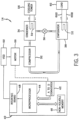
FIG. 3 is a schematic of an embodiment of the vapor compression system ofFIG. 2 , in accordance with an aspect of the present disclosure; -
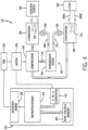
FIG. 4 is a schematic of an embodiment of the vapor compression system ofFIG. 2 , in accordance with an aspect of the present disclosure; -
FIG. 5 is a schematic of an embodiment of a variable speed drive that may be used with the vapor compression system ofFIGS. 2-4 , in accordance with an aspect of the present disclosure; -
FIG. 6 is a circuit diagram of an embodiment of a silicon carbide transistor that may be used with the variable speed drive ofFIG. 5 , in accordance with an aspect of the present disclosure; and -
FIG. 7 is a block diagram of an embodiment of a process for operating a vapor compression system having the silicon carbide transistor ofFIG. 6 , in accordance with an aspect of the present disclosure. - One or more specific embodiments will be described below. In an effort to provide a concise description of these embodiments, not all features of an actual implementation are described in the specification. It should be appreciated that in the development of any such actual implementation, as in any engineering or design project, numerous implementation-specific decisions must be made to achieve the developers' specific goals, such as compliance with system-related and business-related constraints, which may vary from one implementation to another. Moreover, it should be appreciated that such a development effort might be complex and time consuming, but would nevertheless be a routine undertaking of design, fabrication, and manufacture for those of ordinary skill having the benefit of this disclosure.
- Embodiments of the present disclosure are directed towards a heating, ventilating, air conditioning, and refrigeration (HVAC&R) system that uses a variable speed drive having a silicon carbide transistor. Variable speed drives may be coupled to a motor that drives a compressor of the HVAC&R system. More specifically, variable speed drives may be utilized to adjust a speed of the motor. Typically, HVAC&R systems utilize significant amounts of power. Accordingly, enhancing the efficiency of such systems may reduce operating costs by reducing an amount of energy consumed and/or reducing energy loss incurred during operation.
- Variable speed drives may incur losses during operation due to conduction losses and/or switching losses. For example, conduction losses may occur when components of the variable speed drive conduct current (e.g., an insulated-gate bipolar transistor (IGBT) conducts current when in a closed state). Additionally, switching losses may occur when components of the variable speed drive (e.g., an insulated-gate bipolar transistor (IGBT)) switch between an open and a closed state during operation of the variable speed drive. Typically, switching components of the variable speed drive, such as an IGBT module, which also includes a silicon diode. Silicon diodes may be relatively inexpensive, but also have relatively slow switching times. Accordingly, an efficiency of the variable speed drive may be reduced as a result of the switching time for the silicon diode to switch between an open and a closed position.
- Embodiments of the present disclosure relate to variable speed drives that include a silicon carbide transistor in lieu of an IGBT. The silicon carbide transistor may reduce switching losses because the silicon carbide transistor includes a more efficient (e.g., faster) switching time when compared to IGBTs. Incorporating the silicon carbide transistor into variable speed drives may enhance an efficiency of the variable speed drive, and thus, increase the efficiency of the overall HVAC&R system.
- Turning now to the drawings,
FIG. 1 is a perspective view of an embodiment of an environment for a heating, ventilation, air conditioning, and refrigeration (HVAC&R)system 10 in abuilding 12 for a typical commercial setting. The HVAC&Rsystem 10 may include avapor compression system 14 that supplies a chilled liquid, which may be used to cool thebuilding 12. The HVAC&Rsystem 10 may also include aboiler 16 to supply warm liquid to heat thebuilding 12 and an air distribution system which circulates air through thebuilding 12. The air distribution system can also include an air return duct 18, anair supply duct 20, and/or an air handler 22. In some embodiments, the air handler 22 may include a heat exchanger that is connected to theboiler 16 and thevapor compression system 14 by conduits 24. The heat exchanger in the air handler 22 may receive either heated liquid from theboiler 16 or chilled liquid from thevapor compression system 14, depending on the mode of operation of theHVAC&R system 10. TheHVAC&R system 10 is shown with a separate air handler on each floor ofbuilding 12, but in other embodiments, theHVAC&R system 10 may include air handlers 22 and/or other components that may be shared between or among floors. -
FIGS. 2 and3 are embodiments of thevapor compression system 14 that can be used in the HVAC&Rsystem 10. Thevapor compression system 14 may circulate a refrigerant through a circuit starting with acompressor 32. The circuit may also include acondenser 34, an expansion valve(s) or device(s) 36, and a liquid chiller or anevaporator 38. Thevapor compression system 14 may further include acontrol panel 40 that has an analog to digital (A/D)converter 42, amicroprocessor 44, anon-volatile memory 46, and/or aninterface board 48. - Some examples of fluids that may be used as refrigerants in the
vapor compression system 14 are hydrofluorocarbon (HFC) based refrigerants, for example, R-410A, R-407, R-134a, hydrofluoro olefin (HFO), "natural" refrigerants like ammonia (NH3), R-717, carbon dioxide (CO2), R-744, or hydrocarbon based refrigerants, water vapor, or any other suitable refrigerant. In some embodiments, thevapor compression system 14 may be configured to efficiently utilize refrigerants having a normal boiling point of about 19 degrees Celsius (66 degrees Fahrenheit) at one atmosphere of pressure, also referred to as low pressure refrigerants, versus a medium pressure refrigerant, such as R-134a. As used herein, "normal boiling point" may refer to a boiling point temperature measured at one atmosphere of pressure. - In some embodiments, the
vapor compression system 14 may use one or more of a variable speed drive (VSDs) 52, amotor 50, thecompressor 32, thecondenser 34, the expansion valve ordevice 36, and/or theevaporator 38. Themotor 50 may drive thecompressor 32 and may be powered by a variable speed drive (VSD) 52. The VSD 52 receives alternating current (AC) power having a particular fixed line voltage and fixed line frequency from an AC power source, and provides power having a variable voltage and frequency to themotor 50. In other embodiments, themotor 50 may be powered directly from an AC or direct current (DC) power source. Themotor 50 may include any type of electric motor that can be powered by a VSD or directly from an AC or DC power source, such as a switched reluctance motor, an induction motor, an electronically commutated permanent magnet motor, or another suitable motor. - The
compressor 32 compresses a refrigerant vapor and delivers the vapor to thecondenser 34 through a discharge passage. In some embodiments, thecompressor 32 may be a centrifugal compressor. The refrigerant vapor delivered by thecompressor 32 to thecondenser 34 may transfer heat to a cooling fluid (e.g., water or air) in thecondenser 34. The refrigerant vapor may condense to a refrigerant liquid in thecondenser 34 as a result of thermal heat transfer with the cooling fluid. The liquid refrigerant from thecondenser 34 may flow through theexpansion device 36 to theevaporator 38. In the illustrated embodiment ofFIG. 3 , thecondenser 34 is water cooled and includes atube bundle 54 connected to a cooling tower 56, which supplies the cooling fluid to the condenser. - The liquid refrigerant delivered to the
evaporator 38 may absorb heat from another cooling fluid, which may or may not be the same cooling fluid used in thecondenser 34. The liquid refrigerant in theevaporator 38 may undergo a phase change from the liquid refrigerant to a refrigerant vapor. As shown in the illustrated embodiment ofFIG. 3 , theevaporator 38 may include atube bundle 58 having asupply line 60S and a return line 60R connected to acooling load 62. The cooling fluid of the evaporator 38 (e.g., water, ethylene glycol, calcium chloride brine, sodium chloride brine, or any other suitable fluid) enters theevaporator 38 via return line 60R and exits theevaporator 38 viasupply line 60S. Theevaporator 38 may reduce the temperature of the cooling fluid in thetube bundle 58 via thermal heat transfer with the refrigerant. Thetube bundle 58 in theevaporator 38 can include a plurality of tubes and/or a plurality of tube bundles. In any case, the vapor refrigerant exits theevaporator 38 and returns to thecompressor 32 by a suction line to complete the cycle. -
FIG. 4 is a schematic of thevapor compression system 14 with anintermediate circuit 64 incorporated betweencondenser 34 and theexpansion device 36. Theintermediate circuit 64 may have aninlet line 68 that is directly fluidly connected to thecondenser 34. In other embodiments, theinlet line 68 may be indirectly fluidly coupled to thecondenser 34. As shown in the illustrated embodiment ofFIG. 4 , theinlet line 68 includes afirst expansion device 66 positioned upstream of anintermediate vessel 70. In some embodiments, theintermediate vessel 70 may be a flash tank (e.g., a flash intercooler). In other embodiments, theintermediate vessel 70 may be configured as a heat exchanger or a "surface economizer." In the illustrated embodiment ofFIG. 4 , theintermediate vessel 70 is used as a flash tank, and thefirst expansion device 66 is configured to lower the pressure of (e.g., expand) the liquid refrigerant received from thecondenser 34. During the expansion process, a portion of the liquid may vaporize, and thus, theintermediate vessel 70 may be used to separate the vapor from the liquid received from thefirst expansion device 66. Additionally, theintermediate vessel 70 may provide for further expansion of the liquid refrigerant because of a pressure drop experienced by the liquid refrigerant when entering the intermediate vessel 70 (e.g., due to a rapid increase in volume experienced when entering the intermediate vessel 70). The vapor in theintermediate vessel 70 may be drawn by thecompressor 32 through asuction line 74 of thecompressor 32. In other embodiments, the vapor in the intermediate vessel may be drawn to an intermediate stage of the compressor 32 (e.g., not the suction stage). The liquid that collects in theintermediate vessel 70 may be at a lower enthalpy than the liquid refrigerant exiting thecondenser 34 because of the expansion in theexpansion device 66 and/or theintermediate vessel 70. The liquid fromintermediate vessel 70 may then flow in line 72 through asecond expansion device 36 to theevaporator 38. - As noted above, variable speed drives may incur conduction losses and/or switching losses during operation, which leads to a reduction in an efficiency of the variable speed drive. Conduction losses occur when a component of a variable speed drive is conducting electrical current (e.g., when an IGBT is in a closed state). As such, energy input to the variable speed drive is lost in the form of thermal energy (e.g., heat). Additionally, switching losses occur when a component of a variable speed drive transitions between open and closed states (e.g., to adjust an amount or voltage or frequency of power supplied to the motor). For example, a transistor of the variable speed drive may be adjusted between an open and a closed state to adjust a voltage and/or frequency of power ultimately output to the motor. Existing variable speed drives include insulated-gate bipolar transistors (IGBTs), which may include relatively slow switching speeds. Accordingly, an efficiency of the variable speed drive is reduced as a result of the switching speeds of the IGBTs. Embodiments of the present disclosure relate to variable speed drives that have a silicon carbide transistor. The silicon carbide transistor includes quicker switching speeds when compared to IGBTs of existing variable speed drives. Accordingly, including silicon carbide transistors in the variable speed drive may enhance an efficiency of the variable speed drive, and thus, increase an overall efficiency of a HVAC&R system.
- For example,
FIG. 5 is a schematic of thevariable speed drive 52 that includes asilicon carbide transistor 100. As shown in the illustrated embodiment ofFIG. 5 , thevariable speed drive 52 includes arectifier 102, aDC bus 104, and aninverter 106. Therectifier 102 receives alternating current (AC) power at a constant voltage and frequency and converts the AC power into direct current (DC) power. For example, therectifier 102 may receive the AC power from anAC power source 108, which may supply three-phase AC power to thevariable speed drive 52. TheDC bus 104 may then filter and/or stabilize the DC power, such that the DC power is suitable for use by theinverter 106. Theinverter 106 may then transfer the DC power back to AC power that includes a variable voltage and frequency. The AC power from theinverter 106 is utilized to power themotor 50, which drives thecompressor 32 of thevapor compression system 14. - As shown in the illustrated embodiment of
FIG. 5 , thesilicon carbide transistor 100 is included in therectifier 102 and theinverter 106. As such, thesilicon carbide transistor 100 may be utilized to adjust an amount of voltage and/or frequency of the power that is directed to theDC bus 104 and/or themotor 50. The voltage and/or frequency of the power is based on discharge pressure of thecompressor 32. In some embodiments, the voltage and/or frequency of the power is further based on a voltage of the AC power from theAC power source 108, a voltage of the DC power at theDC bus 104, a speed of themotor 50, or a combination thereof. In any case, thesilicon carbide transistor 100 includes a reduced switching speed when compared to existing IGBTs. As such, the variable speed drive efficiency is enhanced and the overall efficiency of thevapor compression system 14 may also increase. -
FIG. 6 is a circuit diagram of an embodiment of thesilicon carbide transistor 100 that may be included in thevariable speed drive 52 of thevapor compression system 14. In some embodiments, an IGBT having a silicon diode may be replaced with the silicon carbide transistor 100 (e.g., a metal-oxide-semiconductor field-effect transistor (MOSFET)). In some embodiments, a circuit board of thevariable speed drive 52 may be modified in order to include thesilicon carbide transistor 100 into thevariable speed drive 52 and improve the efficiency of thevariable speed drive 52. Specifically, a circuit board and/or a gate driver board of thevariable speed drive 52 may be modified to implement thesilicon carbide transistor 100. Additionally, electromagnetic filters and/or other magnetic filters may be included in the circuit board or other suitable locations in thevariable speed drive 52 to accommodate thesilicon carbide transistor 100. A cooling system of thevariable speed drive 52 may also be modified as a result of less thermal energy being created by thesilicon carbide transistor 100 when compared to IGBTs. In any case, thesilicon carbide transistor 100 may reduce switching losses, thereby increasing an efficiency of thevariable speed drive 52. - As discussed above, losses incurred by the
variable speed drive 52 with thesilicon carbide transistor 100 are significantly less than those incurred by the variable speed drive with the typical IGBT with a silicon diode. As such, thevariable speed drive 52 that includes thesilicon carbide transistor 100 achieves an improved efficiency over the variable speed drives that include a typical IGBT with a silicon diode. For example, thevariable speed drive 52 may improve an efficiency of thevapor compression system 14 between 0.25% and 3%, between 0.4% and 2%, or between 0.5% and 1.6%. As is understood, thevapor compression system 14 may consume relatively large amounts of power. As such, improvements in efficiency that are between 0.5% and 1.6% may significantly reduce an amount of power consumption by thevapor compression system 14, and thus, reduce operating costs of thevapor compression system 14. Accordingly, incorporating thesilicon carbide transistor 100 into thevariable speed drive 52 may improve the efficiency of thevapor compression system 14, and thus, reduce operating costs of thevapor compression system 14. -
FIG. 7 is a block diagram of an embodiment of aprocess 150 for operating thevapor compression system 14 having thevariable speed drive 52 with thesilicon carbide transistor 100. For example atblock 152, thecompressor 32 circulates refrigerant through the refrigerant loop of thevapor compression system 14. Additionally, atblock 154, thevariable speed drive 52 supplies power to themotor 50 to drive thecompressor 32. As discussed above, thevariable speed drive 52 includes thesilicon carbide transistor 100, which reduces power losses (e.g., switching losses and/or conduction losses) and increases an efficiency of thevapor compression system 14. - As set forth above, the present disclosure may provide one or more technical effects useful in improving an efficiency of HVAC&R systems. Embodiments of the disclosure include variable speed drives having a silicon carbide transistor, which may include reduced switching times when compared to existing IGBTs. As such, switching losses that occur during operation of the variable speed drive may be reduced, thereby enhancing an efficiency of variable speed drive, and thus, enhancing an efficiency of the overall HVAC&R system. The technical effects and technical problems in the specification are examples and are not limiting. It should be noted that the embodiments described in the specification may have other technical effects and can solve other technical problems.
Claims (9)
- A heating, ventilating, air conditioning, and refrigeration, HVAC&R, system (10), comprising:- a variable speed drive (52) configured to provide power to a motor (50) configured to drive a compressor (32) of the HVAC&R system (10), the variable speed drive comprising:- a rectifier (102) configured to receive alternating current, AC, power from an AC power source (108) and convert the AC power to direct current, DC, power, wherein the AC power comprises a constant voltage and a constant frequency, the rectifier (102) comprising a first silicon carbide transistor (100) configured to adjust a voltage, or a frequency, or both, of power flowing through the variable speed drive (52);- a DC bus (104) configured to receive the DC power from the rectifier (102); and- an inverter (106) configured to receive the DC power from the DC bus (104) and to convert the DC power to AC power having a variable voltage and a variable frequency, the inverter comprising a second silicon carbide transistor (100) configured to adjust a voltage, or a frequency, or both, of power flowing through the variable speed drive (52); and- a controller coupled to each silicon carbide transistor (100) and configured to adjust a state of the first and second silicon carbide transistors (100) based on a discharge pressure of the compressor (32).
- The system of claim 1,
wherein the controller is configured to adjust the state of the first and second silicon carbide transistors (100) based on a speed of the motor (50) and the discharge pressure of the compressor (32). - The system of claim 1 or 2,
wherein the AC power received from the AC power source (108) is three-phase AC power. - The system of claim 3,
wherein the DC bus (104) is configured to receive the DC power from the rectifier (102) and to filter or stabilize the DC power. - The system of one of claims 1 to 4,
wherein the first and second silicon carbide transistors (100) are a metal-oxide-semiconductor field-effect transistor, MOSFET. - The system of one of claims 1 to 5, comprising:- the compressor (32) configured to circulate a refrigerant through a refrigerant loop of the HVAC&R system (10); and- a heat exchanger configured to place the refrigerant in thermal communication with a cooling fluid.
- The system of claim 6, comprising an expansion device (36, 66) configured to reduce a pressure of the refrigerant flowing through the refrigerant loop of the HVAC&R system (10).
- A method for operating the system of one of claims 1 to comprising:- circulating a refrigerant through a refrigerant loop with a compressor (32);- adjusting a frequency, or a voltage, or both of power in the variable speed drive (52) using a silicon carbide transistor (100); and- supplying power to a motor (50) with a variable speed drive (52), wherein the motor (50) is configured to drive the compressor (32), wherein the variable speed drive (52) comprises a rectifier (102) comprising a first silicon carbide transistor (100) and an inverter (106) comprising a second silicon carbide transistor (100),wherein adjusting the frequency, or the voltage, or both of the power in the variable speed drive (52) using the first and second silicon carbide transistors (100) comprises adjusting the frequency, or the voltage, or both of the power based on a discharge pressure of the compressor (32).
- The method of claim 8, wherein adjusting the frequency, or the voltage, or both comprises adjusting the frequency, or the voltage, or both of the power based on the discharge pressure of the compressor (32) and a speed of the motor (50).
Applications Claiming Priority (2)
| Application Number | Priority Date | Filing Date | Title |
|---|---|---|---|
| US201662404648P | 2016-10-05 | 2016-10-05 | |
| PCT/US2017/055381 WO2018067843A1 (en) | 2016-10-05 | 2017-10-05 | Variable speed drive for a hvac&r system |
Publications (2)
| Publication Number | Publication Date |
|---|---|
| EP3523874A1 EP3523874A1 (en) | 2019-08-14 |
| EP3523874B1 true EP3523874B1 (en) | 2025-07-09 |
Family
ID=60191464
Family Applications (1)
| Application Number | Title | Priority Date | Filing Date |
|---|---|---|---|
| EP17791780.4A Active EP3523874B1 (en) | 2016-10-05 | 2017-10-05 | Variable speed drive for a hvac&r system |
Country Status (7)
| Country | Link |
|---|---|
| US (1) | US10859300B2 (en) |
| EP (1) | EP3523874B1 (en) |
| JP (1) | JP2019533417A (en) |
| KR (1) | KR102312058B1 (en) |
| CN (1) | CN110326211A (en) |
| TW (1) | TW201826689A (en) |
| WO (1) | WO2018067843A1 (en) |
Families Citing this family (4)
| Publication number | Priority date | Publication date | Assignee | Title |
|---|---|---|---|---|
| EP3659242A4 (en) * | 2017-07-27 | 2021-04-14 | Flekkefjord Elektro AS | INVERTER ELECTRIC MOTOR |
| USD1073892S1 (en) | 2021-01-26 | 2025-05-06 | Dometic Sweden Ab | Air conditioning housing |
| EP4281300A1 (en) * | 2021-01-26 | 2023-11-29 | Dometic Sweden AB | Air conditioning system for a vehicle |
| WO2022193213A1 (en) * | 2021-03-18 | 2022-09-22 | Johnson Controls Air Conditioning And Refrigeration (Wuxi) Co., Ltd. | Adaptive logic board for variable speed drive for heating, ventilation, air conditioning and refrigeration system |
Citations (16)
| Publication number | Priority date | Publication date | Assignee | Title |
|---|---|---|---|---|
| EP0085285A1 (en) | 1981-12-18 | 1983-08-10 | Institut Cerac S.A. | Compressor drive system |
| JP2008061414A (en) | 2006-08-31 | 2008-03-13 | Daikin Ind Ltd | Power converter |
| JP2008061404A (en) | 2006-08-31 | 2008-03-13 | Daikin Ind Ltd | Power converter |
| JP2008061411A (en) | 2006-08-31 | 2008-03-13 | Daikin Ind Ltd | Power converter |
| WO2009058975A1 (en) | 2007-10-31 | 2009-05-07 | Johnson Controls Technology Company | Control system |
| US7619906B2 (en) | 2005-03-01 | 2009-11-17 | York International Corporation | System for precharging a DC link in a variable speed drive |
| EP2169227A1 (en) | 2007-06-06 | 2010-03-31 | Sanden Corporation | Electric compressor control device |
| WO2012012423A2 (en) | 2010-07-20 | 2012-01-26 | Trane International Inc. | Variable capacity screw compressor and method |
| EP2469201A2 (en) | 2010-12-27 | 2012-06-27 | Mitsubishi Electric Corporation | Heat pump apparatus and control method thereof |
| EP2501030A2 (en) | 2011-03-18 | 2012-09-19 | Mitsubishi Electric Corporation | Inverter controller and refrigerating and air-conditioning unit |
| US8336323B2 (en) | 2008-10-03 | 2012-12-25 | Johnson Controls Technology Company | Variable speed drive with pulse-width modulated speed control |
| WO2015140867A1 (en) | 2014-03-15 | 2015-09-24 | 三菱電機株式会社 | Motor drive control device, compressor, fan, and air-conditioning machine |
| US20150318791A1 (en) | 2014-05-05 | 2015-11-05 | Rockwell Automation Technologies, Inc. | Motor drive with silicon carbide mosfet switches |
| WO2016027357A1 (en) | 2014-08-22 | 2016-02-25 | 三菱電機株式会社 | Electric motor drive device and air-conditioning apparatus using electric motor drive device or refrigeration air-conditioning apparatus using electric motor drive device |
| EP3054585A1 (en) | 2013-09-30 | 2016-08-10 | Mitsubishi Electric Corporation | Motor drive control device, compressor, fan, and air-conditioning device |
| US20160329851A1 (en) | 2015-05-08 | 2016-11-10 | Johnson Controls Technology Company | Variable speed drive with active converter |
Family Cites Families (34)
| Publication number | Priority date | Publication date | Assignee | Title |
|---|---|---|---|---|
| JP2001339975A (en) * | 2000-05-25 | 2001-12-07 | Nikki Denso Kk | Three phase motor regenerative power drive |
| JP2005016859A (en) * | 2003-06-27 | 2005-01-20 | Mitsubishi Electric Corp | Air conditioning system |
| US9300197B2 (en) * | 2004-06-17 | 2016-03-29 | Grant A. MacLennan | High frequency inductor filter apparatus and method of use thereof |
| US10594206B2 (en) | 2004-06-17 | 2020-03-17 | Hans Wennerstrom | High frequency inverter/distributed gap inductor—capacitor filter apparatus and method of use thereof |
| JP4494112B2 (en) * | 2004-07-28 | 2010-06-30 | 三菱電機株式会社 | Inverter control device for air conditioner and air conditioner |
| US7555912B2 (en) | 2005-03-01 | 2009-07-07 | York International Corporation | System for precharging a DC link in a variable speed drive |
| FR2911736B1 (en) | 2007-01-23 | 2009-03-20 | Schneider Toshiba Inverter | DEVICE FOR CONTROLLING A POWER SWITCH AND DRIVER COMPRISING SUCH A DIPOSITIVE. |
| FR2928057B1 (en) | 2008-02-21 | 2012-06-01 | Schneider Toshiba Inverter | DEVICE FOR PROTECTING A SPEED DRIVE INCLUDING FILTERING INDUCTANCE. |
| FR2928056B1 (en) | 2008-02-21 | 2010-02-19 | Schneider Toshiba Inverter | DEVICE FOR PROTECTING A SPEED VARIATOR AGAINST OVERCURRENTS. |
| FR2928058B1 (en) | 2008-02-21 | 2010-02-19 | Schneider Toshiba Inverter | SPEED DRIVE INCLUDING A DEVICE FOR PROTECTION AGAINST OVERCURRENTS AND OVERVOLTAGES. |
| JP4937281B2 (en) * | 2009-01-16 | 2012-05-23 | 三菱電機株式会社 | Motor drive control device, compressor, blower, air conditioner, refrigerator or freezer |
| US8299646B2 (en) * | 2009-07-27 | 2012-10-30 | Rocky Research | HVAC/R system with variable frequency drive (VFD) power supply for multiple motors |
| US8193660B2 (en) * | 2009-07-27 | 2012-06-05 | Rocky Research | HVAC/R system having power back-up system with a DC-DC converter |
| FR2951333B1 (en) * | 2009-10-08 | 2011-10-28 | Schneider Electric Ind Sas | POWER CONVERTER USING NORMALLY CLOSED FIELD EFFECT TRANSISTORS |
| EP2613106B1 (en) | 2010-08-30 | 2015-09-23 | Mitsubishi Electric Corporation | Heat pump device, heat pump system and three-phase inverter control method |
| AU2010362331C1 (en) | 2010-10-15 | 2015-06-25 | Mitsubishi Electric Corporation | Heat pump device, heat pump system, and method for controlling three-phase inverter |
| WO2012086010A1 (en) | 2010-12-21 | 2012-06-28 | 三菱電機株式会社 | Heat pump device, heat pump system, and method for controlling three-phase inverter |
| US9228750B2 (en) * | 2011-01-24 | 2016-01-05 | Rocky Research | HVAC/R system with multiple power sources and time-based selection logic |
| US9077274B2 (en) | 2011-02-07 | 2015-07-07 | Mitsubishi Electric Corporation | Heat pump device, heat pump system, and method for controlling three-phase inverter |
| JP5693714B2 (en) | 2011-04-28 | 2015-04-01 | 三菱電機株式会社 | HEAT PUMP DEVICE, HEAT PUMP SYSTEM, AND INVERTER CONTROL METHOD |
| WO2013046454A1 (en) | 2011-09-30 | 2013-04-04 | 三菱電機株式会社 | Heat pump device, heat pump system, and inverter control method |
| AU2011383457B2 (en) | 2011-12-14 | 2016-01-14 | Mitsubishi Electric Corporation | Heat pump device, and air conditioner, heat pump/hot-water supply machine, refrigerator, and freezer equipped with same |
| EP2803922B1 (en) | 2012-01-04 | 2021-09-29 | Mitsubishi Electric Corporation | Heat pump device, air conditioner, and refrigerator |
| EP2851631B1 (en) | 2012-04-16 | 2020-03-11 | Mitsubishi Electric Corporation | Heat pump device, air conditioner, and cooling machine |
| AU2012383156B2 (en) | 2012-06-20 | 2016-02-25 | Mitsubishi Electric Corporation | Heat pump device, air conditioner, and refrigerating machine |
| US9746216B2 (en) | 2012-06-29 | 2017-08-29 | Mitsubishi Electric Corporation | Heat pump device, heat pump system, air conditioner, and freezer |
| WO2014113777A1 (en) * | 2013-01-21 | 2014-07-24 | Trane International Inc. | Refrigerant compressor drives offering enhanced robustness, efficiency and rated voltage operability |
| CA2913003C (en) | 2013-05-23 | 2017-11-21 | Mitsubishi Electric Corporation | Heat pump device, and air conditioner, heat pump water heater, refrigerator, and freezing machine including heat pump device |
| WO2015056341A1 (en) * | 2013-10-18 | 2015-04-23 | 三菱電機株式会社 | Dc power source device, motor drive device, air conditioner, and refrigerator |
| JP2015084622A (en) | 2013-10-25 | 2015-04-30 | 三菱重工オートモーティブサーマルシステムズ株式会社 | Driving device and driving method for switching element; and vehicular air conditioner |
| CN105981277B (en) * | 2014-02-19 | 2019-04-23 | 三菱电机株式会社 | DC power supply units, motor drives and refrigeration cycle applications |
| JP6333395B2 (en) | 2014-09-26 | 2018-05-30 | 三菱電機株式会社 | HEAT PUMP DEVICE AND AIR CONDITIONER, HEAT PUMP HOT WATER, REFRIGERATOR, AND REFRIGERATOR HAVING THE SAME |
| JP6652928B2 (en) | 2014-11-04 | 2020-02-26 | 三菱電機株式会社 | Heat pump device, and air conditioner, heat pump water heater and refrigerator equipped with the same |
| US9859808B2 (en) | 2016-04-26 | 2018-01-02 | General Electric Company | Power converter topology for use in an energy storage system |
-
2017
- 2017-10-05 US US16/339,332 patent/US10859300B2/en active Active
- 2017-10-05 TW TW106134382A patent/TW201826689A/en unknown
- 2017-10-05 KR KR1020197012500A patent/KR102312058B1/en active Active
- 2017-10-05 WO PCT/US2017/055381 patent/WO2018067843A1/en not_active Ceased
- 2017-10-05 CN CN201780061782.1A patent/CN110326211A/en active Pending
- 2017-10-05 EP EP17791780.4A patent/EP3523874B1/en active Active
- 2017-10-05 JP JP2019518113A patent/JP2019533417A/en active Pending
Patent Citations (18)
| Publication number | Priority date | Publication date | Assignee | Title |
|---|---|---|---|---|
| EP0085285A1 (en) | 1981-12-18 | 1983-08-10 | Institut Cerac S.A. | Compressor drive system |
| US7619906B2 (en) | 2005-03-01 | 2009-11-17 | York International Corporation | System for precharging a DC link in a variable speed drive |
| JP2008061414A (en) | 2006-08-31 | 2008-03-13 | Daikin Ind Ltd | Power converter |
| JP2008061404A (en) | 2006-08-31 | 2008-03-13 | Daikin Ind Ltd | Power converter |
| JP2008061411A (en) | 2006-08-31 | 2008-03-13 | Daikin Ind Ltd | Power converter |
| EP2169227A1 (en) | 2007-06-06 | 2010-03-31 | Sanden Corporation | Electric compressor control device |
| WO2009058975A1 (en) | 2007-10-31 | 2009-05-07 | Johnson Controls Technology Company | Control system |
| US8336323B2 (en) | 2008-10-03 | 2012-12-25 | Johnson Controls Technology Company | Variable speed drive with pulse-width modulated speed control |
| WO2012012423A2 (en) | 2010-07-20 | 2012-01-26 | Trane International Inc. | Variable capacity screw compressor and method |
| EP2469201A2 (en) | 2010-12-27 | 2012-06-27 | Mitsubishi Electric Corporation | Heat pump apparatus and control method thereof |
| EP2501030A2 (en) | 2011-03-18 | 2012-09-19 | Mitsubishi Electric Corporation | Inverter controller and refrigerating and air-conditioning unit |
| EP3054585A1 (en) | 2013-09-30 | 2016-08-10 | Mitsubishi Electric Corporation | Motor drive control device, compressor, fan, and air-conditioning device |
| WO2015140867A1 (en) | 2014-03-15 | 2015-09-24 | 三菱電機株式会社 | Motor drive control device, compressor, fan, and air-conditioning machine |
| US20160380575A1 (en) | 2014-03-15 | 2016-12-29 | Mitsubishi Electric Corporation | Motor drive control device, compressor, air-sending device, and air-conditioning apparatus |
| US20150318791A1 (en) | 2014-05-05 | 2015-11-05 | Rockwell Automation Technologies, Inc. | Motor drive with silicon carbide mosfet switches |
| WO2016027357A1 (en) | 2014-08-22 | 2016-02-25 | 三菱電機株式会社 | Electric motor drive device and air-conditioning apparatus using electric motor drive device or refrigeration air-conditioning apparatus using electric motor drive device |
| US20170138654A1 (en) | 2014-08-22 | 2017-05-18 | Mitsubishi Electric Corporation | Electric motor drive device and air-conditioning apparatus or refrigerating and air-conditioning apparatus using the same |
| US20160329851A1 (en) | 2015-05-08 | 2016-11-10 | Johnson Controls Technology Company | Variable speed drive with active converter |
Non-Patent Citations (7)
| Title |
|---|
| "Intelligent Buildings and Building Automation", 4 December 2009, CRC PRESS LLC, article WANG SHENGWEI: "9 Control and optimization of central chilling systems", pages: 175 - 206, XP055834362 * |
| ANONYMOUS: "Clausius-Clapeyron-Gleichung", WIKIPEDIA, pages 1 - 3, XP093386895, Retrieved from the Internet <URL:https://de.wikipedia.org/w/index.php?title=Clausius-Clapeyron-Gleichung&oldid=155193103> |
| CAUSEY ANDREW E.: "COMPRESSOR LOAD STAND: COMMISSIONING AND CONTROL STRATEGIES", THESIS, PURDUE UNIVERSITY, pages 1 - 112, XP093386900, Retrieved from the Internet <URL:https://apps.dtic.mil/sti/tr/pdf/ADA356197.pdf> |
| KORN, DIETER: "Effizienter Betrieb von Kälteanlagen", 1 September 2014, VDE VERLAG GMBH, ISBN: 978-3-8007-3593-8, article KORN, DIETER: "2 Drehzahlverstellung zur bedarfsabhängigen Regelung von Verdichtern und Verflüssiger-Ventilatoren", pages: 9 - 32, XP009566400 |
| ORELLANA RACCOURSIER ALVARO: "Kompakter rückspeisefähiger Antriebsstromrichter mit SiC-JFETs und sinusförmigen Ausgangsspannungen", UNIVERSITÄT ERLANGEN, pages 1 - 245, XP093386906, ISBN: 978-3-86955-007-7, Retrieved from the Internet <URL:https://cuvillier.de/de/shop/publications/1101-kompakter-ruckspeisefahiger-antriebsstromrichter-mit-sic-jfets-und-sinusformigen-ausgangsspannungen> |
| TRINTIS IONUT, DOUGLASS PHILIP, MAHESHWARI RAMKRISHAN, MUNK-NIELSEN STIG: "SiC heat pump converters with support for voltage unbalance in distribution grids", 2015 17TH EUROPEAN CONFERENCE ON POWER ELECTRONICS AND APPLICATIONS (EPE'15 ECCE-EUROPE), IEEE, 1 September 2015 (2015-09-01) - 2015-09-10, pages 1 - 7, XP093384440, ISBN: 978-1-4799-8277-6, DOI: 10.1109/epe.2015.7311670 |
| XUE, Z. ; SHI, L.: "Modeling and Experimental Investigation of a Variable Speed Drive Water Source Heat Pump", TSINGHUA SCIENCE AND TECHNOLOGY, TSINGHUA UNIVERSITY PRESS, BEIJING, CN, vol. 15, no. 4, 1 August 2010 (2010-08-01), CN , pages 434 - 440, XP027188471, ISSN: 1007-0214 |
Also Published As
| Publication number | Publication date |
|---|---|
| JP2019533417A (en) | 2019-11-14 |
| US10859300B2 (en) | 2020-12-08 |
| WO2018067843A1 (en) | 2018-04-12 |
| KR102312058B1 (en) | 2021-10-14 |
| TW201826689A (en) | 2018-07-16 |
| EP3523874A1 (en) | 2019-08-14 |
| KR20190054170A (en) | 2019-05-21 |
| CN110326211A (en) | 2019-10-11 |
| US20200041185A1 (en) | 2020-02-06 |
Similar Documents
| Publication | Publication Date | Title |
|---|---|---|
| EP2763303B1 (en) | Heat pump device, heat pump system, and inverter control method | |
| AU2011358803B2 (en) | Heat pump device, heat pump system, and control method for three-phase inverter | |
| EP2629029B1 (en) | Heat pump device, heat pump system, and method for controlling three-phase inverter | |
| CN104321596B (en) | Heat pump assembly, air conditioner and refrigeration machine | |
| AU2012377681B2 (en) | Heat pump device, air conditioner, and cooling machine | |
| CN106461278B (en) | Method for operating a cooler | |
| US11486612B2 (en) | Heat pump for a HVACandR system | |
| US10812005B2 (en) | Variable speed drive with a battery | |
| US9631852B2 (en) | System and method for controlling compressor motor voltage | |
| US10859300B2 (en) | Variable speed drive for a HVACandR system | |
| CN105980795A (en) | Motor and drive arrangement for refrigeration system | |
| WO2017120503A1 (en) | Vapor compression system | |
| CN105829810A (en) | Operation of a cascade air conditioning system with two-phase loop | |
| JP7421473B2 (en) | System and method for dual power variable speed drive | |
| US20220252306A1 (en) | Series flow chiller system | |
| JP2015224802A (en) | Refrigeration equipment |
Legal Events
| Date | Code | Title | Description |
|---|---|---|---|
| STAA | Information on the status of an ep patent application or granted ep patent |
Free format text: STATUS: UNKNOWN |
|
| STAA | Information on the status of an ep patent application or granted ep patent |
Free format text: STATUS: THE INTERNATIONAL PUBLICATION HAS BEEN MADE |
|
| PUAI | Public reference made under article 153(3) epc to a published international application that has entered the european phase |
Free format text: ORIGINAL CODE: 0009012 |
|
| STAA | Information on the status of an ep patent application or granted ep patent |
Free format text: STATUS: REQUEST FOR EXAMINATION WAS MADE |
|
| 17P | Request for examination filed |
Effective date: 20190402 |
|
| AK | Designated contracting states |
Kind code of ref document: A1 Designated state(s): AL AT BE BG CH CY CZ DE DK EE ES FI FR GB GR HR HU IE IS IT LI LT LU LV MC MK MT NL NO PL PT RO RS SE SI SK SM TR |
|
| AX | Request for extension of the european patent |
Extension state: BA ME |
|
| DAV | Request for validation of the european patent (deleted) | ||
| DAX | Request for extension of the european patent (deleted) | ||
| STAA | Information on the status of an ep patent application or granted ep patent |
Free format text: STATUS: EXAMINATION IS IN PROGRESS |
|
| 17Q | First examination report despatched |
Effective date: 20200429 |
|
| RAP1 | Party data changed (applicant data changed or rights of an application transferred) |
Owner name: JOHNSON CONTROLS TYCO IP HOLDINGS LLP |
|
| GRAP | Despatch of communication of intention to grant a patent |
Free format text: ORIGINAL CODE: EPIDOSNIGR1 |
|
| STAA | Information on the status of an ep patent application or granted ep patent |
Free format text: STATUS: GRANT OF PATENT IS INTENDED |
|
| RIC1 | Information provided on ipc code assigned before grant |
Ipc: F25B 49/02 20060101ALI20250127BHEP Ipc: H02M 5/458 20060101ALI20250127BHEP Ipc: H02P 27/16 20060101ALI20250127BHEP Ipc: H02P 27/04 20160101AFI20250127BHEP |
|
| INTG | Intention to grant announced |
Effective date: 20250205 |
|
| GRAS | Grant fee paid |
Free format text: ORIGINAL CODE: EPIDOSNIGR3 |
|
| GRAA | (expected) grant |
Free format text: ORIGINAL CODE: 0009210 |
|
| STAA | Information on the status of an ep patent application or granted ep patent |
Free format text: STATUS: THE PATENT HAS BEEN GRANTED |
|
| AK | Designated contracting states |
Kind code of ref document: B1 Designated state(s): AL AT BE BG CH CY CZ DE DK EE ES FI FR GB GR HR HU IE IS IT LI LT LU LV MC MK MT NL NO PL PT RO RS SE SI SK SM TR |
|
| REG | Reference to a national code |
Ref country code: GB Ref legal event code: FG4D |
|
| REG | Reference to a national code |
Ref country code: CH Ref legal event code: EP |
|
| REG | Reference to a national code |
Ref country code: IE Ref legal event code: FG4D |
|
| REG | Reference to a national code |
Ref country code: DE Ref legal event code: R096 Ref document number: 602017090470 Country of ref document: DE |
|
| REG | Reference to a national code |
Ref country code: NL Ref legal event code: MP Effective date: 20250709 |
|
| PG25 | Lapsed in a contracting state [announced via postgrant information from national office to epo] |
Ref country code: PT Free format text: LAPSE BECAUSE OF FAILURE TO SUBMIT A TRANSLATION OF THE DESCRIPTION OR TO PAY THE FEE WITHIN THE PRESCRIBED TIME-LIMIT Effective date: 20251110 |
|
| PG25 | Lapsed in a contracting state [announced via postgrant information from national office to epo] |
Ref country code: NL Free format text: LAPSE BECAUSE OF FAILURE TO SUBMIT A TRANSLATION OF THE DESCRIPTION OR TO PAY THE FEE WITHIN THE PRESCRIBED TIME-LIMIT Effective date: 20250709 |
|
| REG | Reference to a national code |
Ref country code: AT Ref legal event code: MK05 Ref document number: 1812842 Country of ref document: AT Kind code of ref document: T Effective date: 20250709 |
|
| PG25 | Lapsed in a contracting state [announced via postgrant information from national office to epo] |
Ref country code: IS Free format text: LAPSE BECAUSE OF FAILURE TO SUBMIT A TRANSLATION OF THE DESCRIPTION OR TO PAY THE FEE WITHIN THE PRESCRIBED TIME-LIMIT Effective date: 20251109 |
|
| PGFP | Annual fee paid to national office [announced via postgrant information from national office to epo] |
Ref country code: DE Payment date: 20251028 Year of fee payment: 9 |
|
| PG25 | Lapsed in a contracting state [announced via postgrant information from national office to epo] |
Ref country code: NO Free format text: LAPSE BECAUSE OF FAILURE TO SUBMIT A TRANSLATION OF THE DESCRIPTION OR TO PAY THE FEE WITHIN THE PRESCRIBED TIME-LIMIT Effective date: 20251009 |
|
| REG | Reference to a national code |
Ref country code: LT Ref legal event code: MG9D |
|
| PG25 | Lapsed in a contracting state [announced via postgrant information from national office to epo] |
Ref country code: AT Free format text: LAPSE BECAUSE OF FAILURE TO SUBMIT A TRANSLATION OF THE DESCRIPTION OR TO PAY THE FEE WITHIN THE PRESCRIBED TIME-LIMIT Effective date: 20250709 |
|
| PG25 | Lapsed in a contracting state [announced via postgrant information from national office to epo] |
Ref country code: FI Free format text: LAPSE BECAUSE OF FAILURE TO SUBMIT A TRANSLATION OF THE DESCRIPTION OR TO PAY THE FEE WITHIN THE PRESCRIBED TIME-LIMIT Effective date: 20250709 |
|
| PG25 | Lapsed in a contracting state [announced via postgrant information from national office to epo] |
Ref country code: HR Free format text: LAPSE BECAUSE OF FAILURE TO SUBMIT A TRANSLATION OF THE DESCRIPTION OR TO PAY THE FEE WITHIN THE PRESCRIBED TIME-LIMIT Effective date: 20250709 |
|
| PGFP | Annual fee paid to national office [announced via postgrant information from national office to epo] |
Ref country code: FR Payment date: 20251027 Year of fee payment: 9 |
|
| PG25 | Lapsed in a contracting state [announced via postgrant information from national office to epo] |
Ref country code: GR Free format text: LAPSE BECAUSE OF FAILURE TO SUBMIT A TRANSLATION OF THE DESCRIPTION OR TO PAY THE FEE WITHIN THE PRESCRIBED TIME-LIMIT Effective date: 20251010 |
|
| PG25 | Lapsed in a contracting state [announced via postgrant information from national office to epo] |
Ref country code: SE Free format text: LAPSE BECAUSE OF FAILURE TO SUBMIT A TRANSLATION OF THE DESCRIPTION OR TO PAY THE FEE WITHIN THE PRESCRIBED TIME-LIMIT Effective date: 20250709 |
|
| PG25 | Lapsed in a contracting state [announced via postgrant information from national office to epo] |
Ref country code: LV Free format text: LAPSE BECAUSE OF FAILURE TO SUBMIT A TRANSLATION OF THE DESCRIPTION OR TO PAY THE FEE WITHIN THE PRESCRIBED TIME-LIMIT Effective date: 20250709 |
|
| PG25 | Lapsed in a contracting state [announced via postgrant information from national office to epo] |
Ref country code: PL Free format text: LAPSE BECAUSE OF FAILURE TO SUBMIT A TRANSLATION OF THE DESCRIPTION OR TO PAY THE FEE WITHIN THE PRESCRIBED TIME-LIMIT Effective date: 20250709 Ref country code: BG Free format text: LAPSE BECAUSE OF FAILURE TO SUBMIT A TRANSLATION OF THE DESCRIPTION OR TO PAY THE FEE WITHIN THE PRESCRIBED TIME-LIMIT Effective date: 20250709 |
|
| PG25 | Lapsed in a contracting state [announced via postgrant information from national office to epo] |
Ref country code: RS Free format text: LAPSE BECAUSE OF FAILURE TO SUBMIT A TRANSLATION OF THE DESCRIPTION OR TO PAY THE FEE WITHIN THE PRESCRIBED TIME-LIMIT Effective date: 20251009 |
|
| PG25 | Lapsed in a contracting state [announced via postgrant information from national office to epo] |
Ref country code: ES Free format text: LAPSE BECAUSE OF FAILURE TO SUBMIT A TRANSLATION OF THE DESCRIPTION OR TO PAY THE FEE WITHIN THE PRESCRIBED TIME-LIMIT Effective date: 20250709 |
|
| PG25 | Lapsed in a contracting state [announced via postgrant information from national office to epo] |
Ref country code: RO Free format text: LAPSE BECAUSE OF FAILURE TO SUBMIT A TRANSLATION OF THE DESCRIPTION OR TO PAY THE FEE WITHIN THE PRESCRIBED TIME-LIMIT Effective date: 20250709 |
|
| REG | Reference to a national code |
Ref country code: DE Ref legal event code: R026 Ref document number: 602017090470 Country of ref document: DE |
|
| PLBI | Opposition filed |
Free format text: ORIGINAL CODE: 0009260 |
|
| PG25 | Lapsed in a contracting state [announced via postgrant information from national office to epo] |
Ref country code: SM Free format text: LAPSE BECAUSE OF FAILURE TO SUBMIT A TRANSLATION OF THE DESCRIPTION OR TO PAY THE FEE WITHIN THE PRESCRIBED TIME-LIMIT Effective date: 20250709 |
|
| REG | Reference to a national code |
Ref country code: CH Ref legal event code: L10 Free format text: ST27 STATUS EVENT CODE: U-0-0-L10-L00 (AS PROVIDED BY THE NATIONAL OFFICE) Effective date: 20260409 |
|
| PLBI | Opposition filed |
Free format text: ORIGINAL CODE: 0009260 |
|
| PG25 | Lapsed in a contracting state [announced via postgrant information from national office to epo] |
Ref country code: DK Free format text: LAPSE BECAUSE OF FAILURE TO SUBMIT A TRANSLATION OF THE DESCRIPTION OR TO PAY THE FEE WITHIN THE PRESCRIBED TIME-LIMIT Effective date: 20250709 |
|
| PG25 | Lapsed in a contracting state [announced via postgrant information from national office to epo] |
Ref country code: IT Free format text: LAPSE BECAUSE OF FAILURE TO SUBMIT A TRANSLATION OF THE DESCRIPTION OR TO PAY THE FEE WITHIN THE PRESCRIBED TIME-LIMIT Effective date: 20250709 |
|
| REG | Reference to a national code |
Ref country code: CH Ref legal event code: L10 Free format text: ST27 STATUS EVENT CODE: U-0-0-L10-L00 (AS PROVIDED BY THE NATIONAL OFFICE) Effective date: 20260416 |
|
| PLAX | Notice of opposition and request to file observation + time limit sent |
Free format text: ORIGINAL CODE: EPIDOSNOBS2 |
|
| PG25 | Lapsed in a contracting state [announced via postgrant information from national office to epo] |
Ref country code: CZ Free format text: LAPSE BECAUSE OF FAILURE TO SUBMIT A TRANSLATION OF THE DESCRIPTION OR TO PAY THE FEE WITHIN THE PRESCRIBED TIME-LIMIT Effective date: 20250709 |
|
| PG25 | Lapsed in a contracting state [announced via postgrant information from national office to epo] |
Ref country code: EE Free format text: LAPSE BECAUSE OF FAILURE TO SUBMIT A TRANSLATION OF THE DESCRIPTION OR TO PAY THE FEE WITHIN THE PRESCRIBED TIME-LIMIT Effective date: 20250709 Ref country code: SK Free format text: LAPSE BECAUSE OF FAILURE TO SUBMIT A TRANSLATION OF THE DESCRIPTION OR TO PAY THE FEE WITHIN THE PRESCRIBED TIME-LIMIT Effective date: 20250709 |
|
| 26 | Opposition filed |
Opponent name: DIEHL AKO STIFTUNG & CO. KG Effective date: 20260331 |
|
| 26 | Opposition filed |
Opponent name: VAILLANT GMBH Effective date: 20260408 |