EP3523156B1 - Energy transmitter and receiver module - Google Patents
Energy transmitter and receiver module Download PDFInfo
- Publication number
- EP3523156B1 EP3523156B1 EP17793579.8A EP17793579A EP3523156B1 EP 3523156 B1 EP3523156 B1 EP 3523156B1 EP 17793579 A EP17793579 A EP 17793579A EP 3523156 B1 EP3523156 B1 EP 3523156B1
- Authority
- EP
- European Patent Office
- Prior art keywords
- energy
- circuits
- circuit
- agv
- wireless
- Prior art date
- Legal status (The legal status is an assumption and is not a legal conclusion. Google has not performed a legal analysis and makes no representation as to the accuracy of the status listed.)
- Active
Links
Images





Classifications
-
- B—PERFORMING OPERATIONS; TRANSPORTING
- B60—VEHICLES IN GENERAL
- B60L—PROPULSION OF ELECTRICALLY-PROPELLED VEHICLES; SUPPLYING ELECTRIC POWER FOR AUXILIARY EQUIPMENT OF ELECTRICALLY-PROPELLED VEHICLES; ELECTRODYNAMIC BRAKE SYSTEMS FOR VEHICLES IN GENERAL; MAGNETIC SUSPENSION OR LEVITATION FOR VEHICLES; MONITORING OPERATING VARIABLES OF ELECTRICALLY-PROPELLED VEHICLES; ELECTRIC SAFETY DEVICES FOR ELECTRICALLY-PROPELLED VEHICLES
- B60L3/00—Electric devices on electrically-propelled vehicles for safety purposes; Monitoring operating variables, e.g. speed, deceleration or energy consumption
- B60L3/04—Cutting off the power supply under fault conditions
-
- B—PERFORMING OPERATIONS; TRANSPORTING
- B60—VEHICLES IN GENERAL
- B60L—PROPULSION OF ELECTRICALLY-PROPELLED VEHICLES; SUPPLYING ELECTRIC POWER FOR AUXILIARY EQUIPMENT OF ELECTRICALLY-PROPELLED VEHICLES; ELECTRODYNAMIC BRAKE SYSTEMS FOR VEHICLES IN GENERAL; MAGNETIC SUSPENSION OR LEVITATION FOR VEHICLES; MONITORING OPERATING VARIABLES OF ELECTRICALLY-PROPELLED VEHICLES; ELECTRIC SAFETY DEVICES FOR ELECTRICALLY-PROPELLED VEHICLES
- B60L53/00—Methods of charging batteries, specially adapted for electric vehicles; Charging stations or on-board charging equipment therefor; Exchange of energy storage elements in electric vehicles
- B60L53/10—Methods of charging batteries, specially adapted for electric vehicles; Charging stations or on-board charging equipment therefor; Exchange of energy storage elements in electric vehicles characterised by the energy transfer between the charging station and the vehicle
- B60L53/12—Inductive energy transfer
- B60L53/122—Circuits or methods for driving the primary coil, e.g. supplying electric power to the coil
-
- B—PERFORMING OPERATIONS; TRANSPORTING
- B60—VEHICLES IN GENERAL
- B60L—PROPULSION OF ELECTRICALLY-PROPELLED VEHICLES; SUPPLYING ELECTRIC POWER FOR AUXILIARY EQUIPMENT OF ELECTRICALLY-PROPELLED VEHICLES; ELECTRODYNAMIC BRAKE SYSTEMS FOR VEHICLES IN GENERAL; MAGNETIC SUSPENSION OR LEVITATION FOR VEHICLES; MONITORING OPERATING VARIABLES OF ELECTRICALLY-PROPELLED VEHICLES; ELECTRIC SAFETY DEVICES FOR ELECTRICALLY-PROPELLED VEHICLES
- B60L53/00—Methods of charging batteries, specially adapted for electric vehicles; Charging stations or on-board charging equipment therefor; Exchange of energy storage elements in electric vehicles
- B60L53/10—Methods of charging batteries, specially adapted for electric vehicles; Charging stations or on-board charging equipment therefor; Exchange of energy storage elements in electric vehicles characterised by the energy transfer between the charging station and the vehicle
- B60L53/12—Inductive energy transfer
- B60L53/126—Methods for pairing a vehicle and a charging station, e.g. establishing a one-to-one relation between a wireless power transmitter and a wireless power receiver
-
- B—PERFORMING OPERATIONS; TRANSPORTING
- B60—VEHICLES IN GENERAL
- B60L—PROPULSION OF ELECTRICALLY-PROPELLED VEHICLES; SUPPLYING ELECTRIC POWER FOR AUXILIARY EQUIPMENT OF ELECTRICALLY-PROPELLED VEHICLES; ELECTRODYNAMIC BRAKE SYSTEMS FOR VEHICLES IN GENERAL; MAGNETIC SUSPENSION OR LEVITATION FOR VEHICLES; MONITORING OPERATING VARIABLES OF ELECTRICALLY-PROPELLED VEHICLES; ELECTRIC SAFETY DEVICES FOR ELECTRICALLY-PROPELLED VEHICLES
- B60L53/00—Methods of charging batteries, specially adapted for electric vehicles; Charging stations or on-board charging equipment therefor; Exchange of energy storage elements in electric vehicles
- B60L53/60—Monitoring or controlling charging stations
- B60L53/65—Monitoring or controlling charging stations involving identification of vehicles or their battery types
-
- B—PERFORMING OPERATIONS; TRANSPORTING
- B60—VEHICLES IN GENERAL
- B60L—PROPULSION OF ELECTRICALLY-PROPELLED VEHICLES; SUPPLYING ELECTRIC POWER FOR AUXILIARY EQUIPMENT OF ELECTRICALLY-PROPELLED VEHICLES; ELECTRODYNAMIC BRAKE SYSTEMS FOR VEHICLES IN GENERAL; MAGNETIC SUSPENSION OR LEVITATION FOR VEHICLES; MONITORING OPERATING VARIABLES OF ELECTRICALLY-PROPELLED VEHICLES; ELECTRIC SAFETY DEVICES FOR ELECTRICALLY-PROPELLED VEHICLES
- B60L2200/00—Type of vehicles
- B60L2200/40—Working vehicles
- B60L2200/44—Industrial trucks or floor conveyors
-
- Y—GENERAL TAGGING OF NEW TECHNOLOGICAL DEVELOPMENTS; GENERAL TAGGING OF CROSS-SECTIONAL TECHNOLOGIES SPANNING OVER SEVERAL SECTIONS OF THE IPC; TECHNICAL SUBJECTS COVERED BY FORMER USPC CROSS-REFERENCE ART COLLECTIONS [XRACs] AND DIGESTS
- Y02—TECHNOLOGIES OR APPLICATIONS FOR MITIGATION OR ADAPTATION AGAINST CLIMATE CHANGE
- Y02P—CLIMATE CHANGE MITIGATION TECHNOLOGIES IN THE PRODUCTION OR PROCESSING OF GOODS
- Y02P90/00—Enabling technologies with a potential contribution to greenhouse gas [GHG] emissions mitigation
- Y02P90/60—Electric or hybrid propulsion means for production processes
-
- Y—GENERAL TAGGING OF NEW TECHNOLOGICAL DEVELOPMENTS; GENERAL TAGGING OF CROSS-SECTIONAL TECHNOLOGIES SPANNING OVER SEVERAL SECTIONS OF THE IPC; TECHNICAL SUBJECTS COVERED BY FORMER USPC CROSS-REFERENCE ART COLLECTIONS [XRACs] AND DIGESTS
- Y02—TECHNOLOGIES OR APPLICATIONS FOR MITIGATION OR ADAPTATION AGAINST CLIMATE CHANGE
- Y02T—CLIMATE CHANGE MITIGATION TECHNOLOGIES RELATED TO TRANSPORTATION
- Y02T10/00—Road transport of goods or passengers
- Y02T10/60—Other road transportation technologies with climate change mitigation effect
- Y02T10/70—Energy storage systems for electromobility, e.g. batteries
-
- Y—GENERAL TAGGING OF NEW TECHNOLOGICAL DEVELOPMENTS; GENERAL TAGGING OF CROSS-SECTIONAL TECHNOLOGIES SPANNING OVER SEVERAL SECTIONS OF THE IPC; TECHNICAL SUBJECTS COVERED BY FORMER USPC CROSS-REFERENCE ART COLLECTIONS [XRACs] AND DIGESTS
- Y02—TECHNOLOGIES OR APPLICATIONS FOR MITIGATION OR ADAPTATION AGAINST CLIMATE CHANGE
- Y02T—CLIMATE CHANGE MITIGATION TECHNOLOGIES RELATED TO TRANSPORTATION
- Y02T10/00—Road transport of goods or passengers
- Y02T10/60—Other road transportation technologies with climate change mitigation effect
- Y02T10/7072—Electromobility specific charging systems or methods for batteries, ultracapacitors, supercapacitors or double-layer capacitors
-
- Y—GENERAL TAGGING OF NEW TECHNOLOGICAL DEVELOPMENTS; GENERAL TAGGING OF CROSS-SECTIONAL TECHNOLOGIES SPANNING OVER SEVERAL SECTIONS OF THE IPC; TECHNICAL SUBJECTS COVERED BY FORMER USPC CROSS-REFERENCE ART COLLECTIONS [XRACs] AND DIGESTS
- Y02—TECHNOLOGIES OR APPLICATIONS FOR MITIGATION OR ADAPTATION AGAINST CLIMATE CHANGE
- Y02T—CLIMATE CHANGE MITIGATION TECHNOLOGIES RELATED TO TRANSPORTATION
- Y02T90/00—Enabling technologies or technologies with a potential or indirect contribution to GHG emissions mitigation
- Y02T90/10—Technologies relating to charging of electric vehicles
- Y02T90/12—Electric charging stations
-
- Y—GENERAL TAGGING OF NEW TECHNOLOGICAL DEVELOPMENTS; GENERAL TAGGING OF CROSS-SECTIONAL TECHNOLOGIES SPANNING OVER SEVERAL SECTIONS OF THE IPC; TECHNICAL SUBJECTS COVERED BY FORMER USPC CROSS-REFERENCE ART COLLECTIONS [XRACs] AND DIGESTS
- Y02—TECHNOLOGIES OR APPLICATIONS FOR MITIGATION OR ADAPTATION AGAINST CLIMATE CHANGE
- Y02T—CLIMATE CHANGE MITIGATION TECHNOLOGIES RELATED TO TRANSPORTATION
- Y02T90/00—Enabling technologies or technologies with a potential or indirect contribution to GHG emissions mitigation
- Y02T90/10—Technologies relating to charging of electric vehicles
- Y02T90/14—Plug-in electric vehicles
-
- Y—GENERAL TAGGING OF NEW TECHNOLOGICAL DEVELOPMENTS; GENERAL TAGGING OF CROSS-SECTIONAL TECHNOLOGIES SPANNING OVER SEVERAL SECTIONS OF THE IPC; TECHNICAL SUBJECTS COVERED BY FORMER USPC CROSS-REFERENCE ART COLLECTIONS [XRACs] AND DIGESTS
- Y02—TECHNOLOGIES OR APPLICATIONS FOR MITIGATION OR ADAPTATION AGAINST CLIMATE CHANGE
- Y02T—CLIMATE CHANGE MITIGATION TECHNOLOGIES RELATED TO TRANSPORTATION
- Y02T90/00—Enabling technologies or technologies with a potential or indirect contribution to GHG emissions mitigation
- Y02T90/10—Technologies relating to charging of electric vehicles
- Y02T90/16—Information or communication technologies improving the operation of electric vehicles
-
- Y—GENERAL TAGGING OF NEW TECHNOLOGICAL DEVELOPMENTS; GENERAL TAGGING OF CROSS-SECTIONAL TECHNOLOGIES SPANNING OVER SEVERAL SECTIONS OF THE IPC; TECHNICAL SUBJECTS COVERED BY FORMER USPC CROSS-REFERENCE ART COLLECTIONS [XRACs] AND DIGESTS
- Y02—TECHNOLOGIES OR APPLICATIONS FOR MITIGATION OR ADAPTATION AGAINST CLIMATE CHANGE
- Y02T—CLIMATE CHANGE MITIGATION TECHNOLOGIES RELATED TO TRANSPORTATION
- Y02T90/00—Enabling technologies or technologies with a potential or indirect contribution to GHG emissions mitigation
- Y02T90/10—Technologies relating to charging of electric vehicles
- Y02T90/16—Information or communication technologies improving the operation of electric vehicles
- Y02T90/167—Systems integrating technologies related to power network operation and communication or information technologies for supporting the interoperability of electric or hybrid vehicles, i.e. smartgrids as interface for battery charging of electric vehicles [EV] or hybrid vehicles [HEV]
-
- Y—GENERAL TAGGING OF NEW TECHNOLOGICAL DEVELOPMENTS; GENERAL TAGGING OF CROSS-SECTIONAL TECHNOLOGIES SPANNING OVER SEVERAL SECTIONS OF THE IPC; TECHNICAL SUBJECTS COVERED BY FORMER USPC CROSS-REFERENCE ART COLLECTIONS [XRACs] AND DIGESTS
- Y04—INFORMATION OR COMMUNICATION TECHNOLOGIES HAVING AN IMPACT ON OTHER TECHNOLOGY AREAS
- Y04S—SYSTEMS INTEGRATING TECHNOLOGIES RELATED TO POWER NETWORK OPERATION, COMMUNICATION OR INFORMATION TECHNOLOGIES FOR IMPROVING THE ELECTRICAL POWER GENERATION, TRANSMISSION, DISTRIBUTION, MANAGEMENT OR USAGE, i.e. SMART GRIDS
- Y04S30/00—Systems supporting specific end-user applications in the sector of transportation
- Y04S30/10—Systems supporting the interoperability of electric or hybrid vehicles
- Y04S30/14—Details associated with the interoperability, e.g. vehicle recognition, authentication, identification or billing
Definitions
- the invention pertains to the technical field of wireless charging stations for batteries of vehicles for industrial environments, industrial vehicles such as AGVs (automated guided vehicles).
- the invention specifically provides an improved modular system for wireless power transfer for these industrial vehicles, maximizing efficiency of energy transfer and reducing necessary charging time by a flexible charging process.
- the present invention relates to a charging equipment comprising an energy transmitter module and an energy receiver module. Embodiments of the present invention are described further below.
- the present invention provides a method as defined in claim 1.
- the charging equipment comprises an energy transmitter module (100) (TX) and an energy receiver module (101) (RX).
- the TX module (100) is connected to the grid or to a DC link voltage.
- the RX box (101) has a Near Field (NF) transmitter (902) (110) sending an identification from AGV receiver module (101) to charger transmitter module (100) through an NF receiver (1000) (109).
- This identification might be and serial number, a wireless communication address, .... This information is communicated from (110) to (109).
- Receiving the magnetic near field on (109) shows that an AGV is present at the charge module and optionally it indicates that the AGV is aligned to the charger.
- the data communication can be 2 ways.
- the wireless module (107) and (108) try to make connection. After making connection, a communication link is established between the AGV module and its charge module. In that case the NF is not needed any more and power transfer can be initiated.
- the AGV wireless charging system is built out of a TX module (200) which is called the charger module and a RX module (201) which is placed on the AGV.
- the primary TX module (200) contains in this case the wireless charging electronics.
- the TX coil is integrated in the wireless power TX module (200), but could be a lose part too, that could e.g. be mounted separately in the charging station or in the floor.
- the RX coil is integrated in the wireless power RX module (201) but could be a loose part too, that could e.g. be mounted separately in the AGV.
- the AGV RX receiver (300) module consists out of a front cover (310) being plastic to allow the magnetic field to come through.
- a shield back cover (305) closes the electronics housings and provides electromagnetic shielding.
- the AGV RX module (300) contains the RX receiver electronics. It has openings for (309) for air inlet and openings (307) for air outlet.
- the module has a connection for the output minus voltage and a connector (301) for the plus voltage output.
- Connector (301) allows communication busses (e.g. CAN) to connect to the AGV and to connect to parallel modules.
- Connector (302) provides user inputs and outputs.
- the flange (306) allows the RX part (300) to be integrated in an AGV.
- the transmit module (400) is composed out of the wireless charging electronics and the primary TX coil.
- the module has input power connectors (402) that can be fed at 3PH AC voltage or DC voltage.
- the module has a input connector (404) providing a connection for a communication bus to the charging station or industrial installation controller or to other modules (400).
- the transmitting coil is covered by a plastic front cover (411).
- the TX module has air inlet openings (401) and air outlets (406) for cooling purposes.
- the coupler construction comprises a shielding plate (504) that holds ferrite (502), plastic isolator and wire ( Figure 12 ) (1200).
- TX coil and RX coil can have different ferrite construction, shield construction, plastic construction and different number of windings and different wire.
- multiple ferrites (507) are providing a gateway for the magnetic flux from TX coil to RX coil and from RX to TX.
- the metal coil holder (504) holds ferrites (503) that provide a flux path for the magnetic field under the coil.
- ferrites (503) that provide a flux path for the magnetic field under the coil.
- a plastic part On top of the ferrite (503), (506) and (507), a plastic part provides insulation between the holder (504), ferrite (503, 506 and 507) and the wire (1201).
- This plastic part has the following functions:
- the ferrite at the sides (506) has similar height as the flange (504) so that the metal is saved from the major part of the magnetic field. If the ferrite would not be there or be lower that the flange, the eddy current losses in the flange would be high. So it has been found that at least equal ferrite height is required.
- the RX module (201) contains the RX (701) coil and the RX electronics (702) (703), (704), (705) and (706) and optionally (711) (712) OR (709) and (710).
- the RX module also contains a controller.
- the TX transmitter module (200) (400) contains electronics to drive the primary TX coil.(804) that is held into the primary coupler holder (500).
- This electronics receive a + (808) and - (809) from the input connector (402) or from and internal grid rectifier. (808) and (809) form a DC link that holds two halve bridges (805) and (806) forming together a full bridge inverter.
- the halve bridge point (802) is connected to an impedance Z towards the first TX coil (804) end.
- the other half bridge point (803) is connected to an impedance Z towards the second TX coil (804) end.
- the full bridge (805) - (806) will be switched as shown in figure 6 , where (25) shows the voltage on (802) and (26) shows the voltage on (803). Each period (30), (31), ... represents the switching frequency. By keeping the switching pattern and in (25) and (26), the coil sees the differential voltage (27). Using the switching pattern (25) and (26), the switching losses can be equalised over both half bridges (802) and (803).
- a near field antenna is installed.
- the NF coil will act as a transmitter.
- the NF coil will act as a receiver.
- the transmitter NF coil (901) will be driven by an electronic circuit (902) with a frequency and on/off modulation or will be driven with frequencies and FSK modulation.
- the modulator circuit can be connected to the driver circuit (902) through signal (900).
- the circuit (902) can be driven by a circuit (1100) that acts as a boost converter boosting an available voltage to a suitable voltage.
- a shut-down signal (1101) can be made available to shut off the NF transmitter (902).
- the NF coil (1001) that is placed at position (505) receives the NF magnetic field signal from the transmitter coil (901) and filters this coil with a band pass filter.
- a comparator OP1 detects the signal and demodulates the signal to the signal (9002).
- the concept is that way that the when the AGV arrives at the charging station, it sends out the identification information including its wireless address. Then the charger communicates further with the AGV.
- This wireless communication includes:
- the present invention concerns a method and systems for wireless power transfer to electric vehicles, preferably AGVs.
- a compartment refers to one or more than one compartment.
- energy storage element refers generally to any element or component capable of rechargeable energy storage, thus comprising batteries . It furthermore is in not necessarily reduced to a single battery or energy storage element, but could also describe a battery pack which combines several separate batteries into a unit that allows to install said battery pack more easily, instead of installing the batteries separately. Furthermore, such a battery pack can be provided with extra features, for instance allowing data transfer (in one or both ways) between the battery pack and other systems, preferably the power transfer system of the invention.
- wireless energy transfer station or “charging station” refers to a system designed for inductively charging an energy storage element (or several) of an AGV. This can be achieved by a so-called charging post, where the separate energy transmitting circuits are stacked in a vertical plane, or a charging mat or floor, where the energy transmitting circuits are provided in a horizontal plane.
- the term "energy transmitting circuit” refers to a circuit designed to generate a magnetic field for power transfer with a coupling element, preferably with a coil.
- the term "energy receiving circuit” refers to a circuit designed to inductively couple to an energy transmitting circuit, and to generate an induced current from magnetic fields picked up by a coupling element, preferably a coil.
- AGV can refer to typical AGVs such as forklifts, but also to composite systems, wherein the composite system is built up from a number of AGVs and/or functional AGV slave modules, possibly detachable (cobots, tools, machinery, industrial robots, systems designed for a number of specific functions).
- the parts of the composite system can furthermore be equipped with a personal battery or batteries.
- European patent application with application number EP16187684.2 .
- the energy transmitting/receiving circuits and the transmitting/receiving controllers are described as separate elements. While this is true, in reality the latter will typically be built into the former. As such, it is possible that the transmitting/receiving controllers are comprised in the energy transmitting/receiving circuits, although this is not necessarily the case.
- the invention provides a method for wireless energy transfer from a wireless energy transfer station to an automated guided vehicle (AGV), whereby said wireless energy transfer station comprises two or more energy transmitting circuits, each preferably comprising a coil and a resonant capacitor, and whereby said AGV comprises at least one energy storage element, preferably a battery, and two or more energy receiving circuits, each preferably comprising a coil and a resonant capacitor, configured for wirelessly receiving energy from one of said energy transmitting circuits and configured for charging said at least one energy storage element with said wirelessly received energy, comprising the following steps:
- the proposed method remedies several of prior art shortcomings.
- One of those is the inability to efficiently provide energy at high rates (especially in providing high currents to the energy storage element) in order to fully charge an energy storage element rapidly.
- This can only be achieved by using exorbitantly high currents in the charging station and thereby transferring great amounts of energy.
- by using such high levels of current not only is a dangerous situation created (both for human operators as well as for the vehicles itself, as an accident can easily damage the subtle circuitry or could start a fire in case of short-circuiting.
- Each of the transmitting circuits that actively participates in a power transfer is inductively coupled with a receiving circuit and induces a current in said receiving circuit, again side current being relatively low and thus not requiring specialized components or causing undesirable losses.
- the currents of each of the receiving circuits in use are then provided in parallel with respect to each other, to the energy storage element. This is preferably the only part of the circuit where a high current is actually produced. By limiting the high current to this section and thus the need for higher quality components, the costs remain limited as well.
- the wireless energy transfer station can couple a desired amount of transmitting circuits depending on the number of receiving circuits (and/or the physical configuration thereof) to provide an optimal energy transfer.
- This match in transmitting and receiving circuits can be achieved in a number of ways, for instance by recognition (IR or others) by the separate circuits that their counterpart is well enough aligned for coupling, or can be by a transmission of information concerning the number and/or physical configuration (for instance, vertical stack, horizontal stack, ...) of the receiving circuits to the other side (side of the charging station), thus enabling the correct transmitting circuits to be used for the power transfer.
- the energy transmitting circuits are each separately controlled by a transmitting controller (and thus separately provided with one).
- Each of these transmitting controllers is configured to be able to control step c of the method, transferring energy from the energy transmitting circuit to the energy receiving circuit. This allows the charging station to overcome possible malfunction or problems in case only one central transmitting controller is used that directs all of the separate transmitting circuits. Furthermore, it allows a more complex control and the provision of a more performant, individual operation regime of the transmitting circuits themselves to optimize the energy transfer achieved.
- the energy receiving circuits are each separately controlled by a receiving controller (and thus separately provided with a receiving controller). This will allow the separate energy receiving circuits to be able to carry out a wireless energy transfer, should one of said circuits or a sole receiving controller (controlling the entire receiving circuit) malfunction, or not be able to correctly align with an energy transmitting circuit, or should other problems arise.
- each energy receiving circuit can be individually optimized as the receiving controller can calibrate the operation regime of each energy receiving circuit separately.
- the energy transmitting circuits are driven by two half bridges.
- each of the energy transmitting circuits of the wireless energy transfer station comprises a separate, associated transmitting controller, whereby a master energy receiving circuit is appointed among one of the energy receiving circuits for directing (driving) the transmitting controllers and a master energy transmitting circuit.
- the wireless energy transfer station and the AGV are adapted for wireless communication, preferably via near-field communication (NF) and optionally via a second wireless communication bus, said method further comprising the following steps:
- the AGV Upon arrival of an AGV to the charging station, the AGV sends a NF signal trough (101) to the charging station (105).
- This signal can optionally contain data information with the identifier of the AGV, with the address of the wireless communication device or a serial number as per examples.
- the charging station When the charging station has received such information, its wireless communication circuit (104) will make communication link to the wireless communication circuit (104) of the AGV.
- Each 'aligned module pair RX and TX' tries to make connection, by first sending the NF information from AGV to Charger station and consequently make a wireless connection.
- the RX circuits can exchange the communicated information through there interconnection bus, e.g. a CAN bus. In this way, a system with two or more paired modules can continue operation with one wireless link only.
- the wireless link can also be a gateway for information receiving from the AGV customer interface (e.g. CAN) towards the charger stations' customer interface. This brings a free of charge (surplus) functionality available for to the customer.
- AGV customer interface e.g. CAN
- surplus free of charge
- Each paired module exchanges independently energy from the charger circuit to the AGV receiver circuit. This exchange of energy is controlled by a controller (109, 109b) in each of the charger station transmitting circuits and AGV receiving circuits.
- a customer can manually choose a master circuit (receiving and/or transmitting) on the AGV side and/or on the charging station side which controls the energy transfer between charging station and AGV. Alternatively, these are automatically chosen.
- the AGV will communicate a desired voltage setpoint and/or current setpoint (or power setpoint) to the charging station. This instruction is then divided by the master transmitting circuit over one or more of the energy transmitting circuits according to maximal power and/or current output per transmitting circuit.
- a master transmitting circuit was appointed, which then divides the to be provided required power supply over 3 transmitting circuits of the charging station (evenly or not, depending on specific characteristics of the circuits - possibly as the circuits are configured for different power/current outputs to better suit variations in AGV power/current requirements for charging), which couple with 3 of the receiving circuits of the AGV.
- This is in practice accomplished by the master transmitting circuit controlling the operating current and voltage for each of the transmitting circuits that are used in the energy transfer.
- one of the circuits in the charging station preferably operates as a master circuit and one of the circuits in the AGV can operate as a master circuit.
- the master circuit in the charging station has the responsibility to split the e.g. current setpoint for the charging operation between the different paired modules.
- a master transmitting circuit and/or at the AGV receiver side a master receiving circuit is appointed. This is possible since the energy transmitting controllers, which direct the transmitting circuits are linked by one or more communication interfaces. Alternatively or additionally, same applies to the energy receiving circuits and receiving controllers.
- near-field communication is ideally suited for the purpose of communication between the charging station and the AGV.
- Other types of communication typically rely on optical connections, but optical connections can easily be disrupted or blocked. They are for instance very sensitive to dirt or dust that could block optical gates and thus disable connection. Since dust and dirt are very relevant in industrial conditions, such as in warehouses, factories and others, this is a very real problem.
- NF does not need a direct visual line to communicate, and can be used even when the charging station is operational (and strong electromagnetic fields are present which could disrupt other conventional communication techniques), and furthermore allows bidirectional information exchange. Of course, alternatives are possible such as WiFi or others.
- the information to be exchanged can furthermore comprise a state of charge of the energy storage element, a desired (or required) output current setpoint (and/or power and/or voltage) and others. Communication may or may not continue during charging, for instance to indicate when the desired (required) current is not achieved on the receiving side so adjustments can be made on the side of the charging station (for instance more or less current, higher voltages, adjustment in alignment of AGV to charging station, load adjustments, ). Due to the bidirectional nature of the information exchange, the charging station can also (repeatedly or periodically) supply to the AGV instructions to improve alignment (for instance changing distance and/or orientation of AGV with respect to the charging station) in order to optimize the coupling.
- AGVs electric vehicles or AGVs
- AGVs are present in most situations (for instance factory work floor), and need to be controlled carefully in order to optimize charging (for instance through preventive charging of some vehicles to avoid conflict of too many vehicles needing charging at one point in time).
- These can be controlled from a central point, which assigns tasks to the separate vehicles and can obtain exact positions and orientations of the vehicles (with for instance individual digital addresses). This could allow the central point to also direct charging and specifically correct alignment of the vehicle, thereby ensuring correct alignment of (a part of) the energy receiving circuits with respect to (a part of) the energy transmitting circuits.
- this can be controlled from the central point, the applicant notes that this can be augmented by further communication between the charging station and the vehicle or AGV, for instance through NF or a sensor that can detect sufficient alignment (which can in turn be provided back to the central point in order to adjust the position and/or orientation of the AGV).
- a filter is be provided to further adjust the rectified current before providing it to the energy storage element.
- the energy transferring circuits are configured to employ hard switching in certain operation points.
- the circuits can comprise silicon carbide power components and/or gallium nitride power components or others to reduce losses when operating under a hard switching pattern.
- the energy transferring circuits can be configured to be able to operate both under hard switching and under soft switching.
- the energy receiving circuits generate an output voltage that is placed over the energy storage element, whereby said output voltage is substantially equal to the normal voltage of the energy storage element plus the voltage drop over possible circuitry and cablings the energy storage element is possibly incorporated in.
- the output voltage in case of a so-called load dump (which may cause problems such as voltage spikes and damage to components) is limited by providing dump circuitry (for instance a resistor, varistor, TVS diodes, or others) to the energy receiving circuits (can be provided separately or for several of said energy receiving circuits).
- Said dump circuitry is designed to reduce or limit a voltage spike in case of a sudden disconnection (from the energy storage element).
- the dump circuitry When the dump circuitry is activated (to be understood as that the output voltage is substantially placed over the dump circuitry (such as when the energy storage element is disconnected), a communication is done to the charging station (or to the energy transferring circuits) to stop the power transfer.
- the dump circuitry is configured to withstand the output voltage during a short time (and to be able to dissipate the power from the energy receiving circuit or circuits), which short time is the time between detection of the load dump until the power transfer is stopped.
- there may be several dump circuitries present for instance one for each energy receiving circuit), and a number of dumps is activated (for instance sequentially) accordingly as the power transfer necessitates. This may be accomplished by initially using a single dump circuitry. Should it be unable to dissipate all of the power generated by the energy receiving circuits, the output voltage will rise and a second dump circuitry can be used, doubling power dissipation possibilities, and so on.
- the invention provides a wireless energy transfer station for wireless energy transfer from the wireless energy transfer station to automated guided vehicles (AGVs), whereby said AGVs comprise one or more energy storage elements and two or more energy receiving circuits, preferably comprising a coil and a resonant capacitor, configured for receiving energy through wireless energy transfer and configured for charging said energy storage element with said received energy, whereby the wireless energy transfer station comprises:
- the transmitting controllers will typically be built into or onto the energy transmitting circuit it is associated to (amongst others, to drive it more efficiently), so a transmitting controller is provided with each energy transmitting circuit. Furthermore, only energy transmitting circuits with a functioning transmitting controller will be allowed to inductively couple to an energy receiving circuit. A similar provision preferably applies to the energy receiving circuits and the receiving controllers.
- the energy transmitting circuits are modular and can be removed from or more added to the wireless energy transfer station in order to satisfy requirements in output current. It is presumed that the energy transmitting circuits can be placed in such a way that they align with standard configurations of the energy receiving circuits on the AGV (for instance, distances between the separate energy receiving circuits). Alternatively, the wireless energy transfer station can displace (part of) the energy transmitting circuits (automatically) to better align with (part of) the energy receiving circuits. Again, the previous assertions apply concerning the specific structure of the circuits and that typically a certain part on each side will need to be aligned with respect to each other.
- the charging station will comprise a plurality (2, 3, 4, 5, 6, 7, 8, 9, 10, 12, 15, 20 or more) of energy transmitting circuits.
- the charging station can be designed to enable charging of several AGVs at once, for instance by having a plurality of energy transmitting circuits on a front side of the charging station, as well as on another side (back side for instance) of the charging station (and optionally on more sides), said sets of energy transmitting circuits being able to be controlled independently from each other, thereby allowing charging of two (or more) AGVs at once.
- the charging station can be adapted to couple with a wide variety of AGVs which can each have particular configurations of energy receiving circuits (number as well as physical configuration).
- the energy transmitting circuits (or parts thereof, especially the coupling elements, preferably a coil) can be displaced with respect to the charging station to better align with the energy receiving circuit (or part thereof, the coupling elements and again preferably a coil), and thereby achieve a more efficient power transfer.
- the transmitting controllers are adapted to, based on feedback it may receive from the AGV which is being charged, to adjust power provided to separate energy transmitting circuits in order to better attune the currents and voltages that are induced in the energy receiving circuits on each other, thereby creating a more stable charging current for the energy storage element.
- the feedback between charging station and AGV may happen through NF, but of course other options exist such as WiFi, and/or possibly through a central control point.
- the energy transferring circuits are provided with power via three-phase electric power supply, or alternatively via two-phase electric power supply, or can further alternatively be fed via DC electric power supply, preferably through a pluggable connector.
- At least one, preferably each of the transmitting controllers is configured to drive the energy transmitting circuits via two half bridges per transmitting controller.
- the transmitting controllers are configured to drive the inductively coupled energy transmitting circuits at different frequencies.
- the transmitting controllers By operating the energy transmitting circuits on different frequencies, this allows an entirely independent operation of the energy transmitting circuits with respect to each other, and would prevent the malfunctioning of one of the energy transmitting circuits to affect the others.
- the different frequencies will provide a more equalized total output voltage provided by the energy transmitting circuits.
- the wireless energy transfer station is configured for wireless communication from (and/or to) an AGV via a communications link, preferably via near-field communication (NF) and optionally a second wireless communication, and acquiring AGV information comprising the number of operational energy receiving circuits on the AGV, and whereby the transmitting controllers are configured to determine based on the AGV information which of the energy transmitting circuits are used in a wireless energy transfer to the AGV.
- NF near-field communication
- the invention provides a wireless energy receiving system for charging at least a battery, of an AGV, whereby said wireless energy charging system is comprised in the AGV and electrically connected to said at least one battery the wireless energy receiving system comprising:
- the system described above can be provided to one or more AGVs, of a fleet for instance, which then can charge in a wireless energy transfer station as described in this document, and/or according to the method discussed in the document.
- the advantages of the abovementioned charging station and wireless energy transfer method are thus clearly applicable to the wireless energy receiving system as well.
- the possible malfunctioning of a sole controller is averted, or in case of impossible linkup, or should other problems arise.
- the wireless energy receiving system comprises means for communicating with a wireless enerav transfer station.
- Said means are configured for connecting a controller unit (for instance an ECU or a battery management system (BMS) of the AGV) of the AGV to said wireless energy transfer station.
- BMS battery management system
- This allows for the communication of information relevant to the energy transfer, for instance, the number of energy receiving circuits (operational) comprised in the wireless energy receiving system, the physical configuration thereof, other parameters, for instance desired output current, desired output voltage.
- feedback can be sent during the energy transfer, for instance indications whether or not a desired output current is achieved (and possibly the difference between actual and desired output current), or a desired output voltage (again, possibly with the difference between actual and desired output voltage), which the wireless energy transfer station can then use to adjust its operational parameters (ranging from frequency, switching patterns, voltages, currents, distance and/or orientation of AGV to charging station and others).
- the energy receiving circuits comprise a rectifier and one or more filters and dump circuits.
- a schematic representation is shown of a wireless energy transfer station (1), which comprises two energy transmitting circuits (5a, 5b), which in turn each comprise a coupling element, a coil (60) in this case.
- a wireless energy receiving system (2) is shown, which comprises two energy receiving circuits (6a, 6b), which in turn comprise a coupling element, a coil (49) in this case, as well, and is electrically connected to an energy storage element (7). Note that the number of circuits displayed (on each side) in the example is purely random, and possible more circuits can be present at any side (transmitting and/or receiving) but these are not participating in the power transfer at hand.
- the energy transmitting circuits (5a, 5b) can each comprise a transmitting controller (which may communicate with each other wired and/or wireless (12), and is visible as element 109a in Figure 18 ), said transmitting controllers being able to adapt the power provided by a power supply and determine the current and voltage provided to the coil (60).
- a single control unit can be provided between the power supply and the energy transmitting circuits (5a, 5b), and can separately control said energy transmitting circuits (5a, 5b).
- the coils (60) of the energy transmitting circuits (5a, 5b) are aligned with the coils (49) of the energy receiving circuits (6a, 6b) for inductive coupling and wireless power transfer.
- the precise process of the inductive power transfer between the (primary) coils (60) and the (secondary) coils (49) will not be discussed in depth in this document, as this is simply the principle under which a transformer operates and should be considered as known by any expert in the field.
- an AC current through the coils (60) of the energy transmitting circuits (5a, 5b) will induce induced currents through the coils (49) of the energy receiving circuits (6a, 6b) (at least of those that are aligned with an energy transmitting circuit that is operational). These induced currents will then be provided to the energy storage element (7) in parallel with respect to each other, whereby the normal output voltage of the energy storage element (7) is upheld. As mentioned before, this can be ensured by adapting some parameters on the transmitting side (1) and/or on the receiving side (2). By parallelizing the multiple induced currents of the energy receiving circuits (5a, 5b), a high current can be provided to the energy storage element, but said high current is limited to only this section, which furthermore can be effectively shielded for safety reasons.
- the charging station (1) and the wireless energy receiving system (2) may be adapted to communicate with each other through a communication bus (10, 11).
- this communication is effected through near-field communication (NF), and optionally through a second wireless communication.
- NF near-field communication
- Figure 14 shows a schematic embodiment of part of an energy transmitting circuit where an impedance (Z) is provided on each terminal of the coil (60), and where two half bridges (15, 16) further drive the voltage and current through the coil (60).
- Figure 18 shows a more detailed representation of a wireless energy transfer station and energy receiving system.
Landscapes
- Engineering & Computer Science (AREA)
- Power Engineering (AREA)
- Transportation (AREA)
- Mechanical Engineering (AREA)
- Life Sciences & Earth Sciences (AREA)
- Sustainable Development (AREA)
- Sustainable Energy (AREA)
- Computer Networks & Wireless Communication (AREA)
- Charge And Discharge Circuits For Batteries Or The Like (AREA)
- Measuring Fluid Pressure (AREA)
- Radar Systems Or Details Thereof (AREA)
- Burglar Alarm Systems (AREA)
Description
- The invention pertains to the technical field of wireless charging stations for batteries of vehicles for industrial environments, industrial vehicles such as AGVs (automated guided vehicles). The invention specifically provides an improved modular system for wireless power transfer for these industrial vehicles, maximizing efficiency of energy transfer and reducing necessary charging time by a flexible charging process.
- Due to the strong increase in use of industrial electric vehicles (and/or hybrid vehicles), for instance AGVs, a necessity has risen for a charging system and method that can rapidly charge a battery or energy storage element (such as supercapacitors and/or ultracapacitors) of said vehicles with more flexibility than the current systems provide. Typically, these systems are limited in several ways. The older generations of energy transfer for instance required a mechanical connection between the charging station and the receiving vehicle. However, this causes a fast degradation of the contact points, both due to mechanical damage (from the contacts and others), as well as pollution of the contact points (for instance due to the environment) which lead to the need of frequent repairs and replacing of components. Furthermore, these mechanical contacts can be dangerous for humans. Contactless charging also makes charging possible in food factories, pharmaceutical and medical factories as an example. This has led to the rise in contactless charging technologies. Many systems are currently on the market for wireless energy transfer, most by electromagnetic induction between a coil on the transmitting end and a coil on the receiving end. However, the applicant observed that the currently provided systems still are not able to provide a flexible and fast wireless charging method, while keeping certain safety precautions such as low voltages and/or currents at the charging station.
- Disclosed in the document
US 2011/0285349 is a charging system focusing on an optimal alignment of the wireless charging station and the energy receiving system of the vehicle. As this can only optimize a power transfer, it has little to no effect on actually increasing the capacity for power transfer as is desired. - Other systems proposed in the prior art would simply increase the voltage and current on the transmitting side in order to increase the amount of energy that is transferred. However, this can create unsafe working conditions due to danger of accidents when dealing with such currents and voltages, and are extremely demanding on the systems handling these, requiring both a more expensive system on both ends (transmitter side and receiver side), and a far more frequent repair and replacement downtime (and cost). As such, these systems are to be dismissed as an inefficient and brute force solution to the problem. An example of such a system can for instance be found in the document
US 2013/0188397 . - Further contactless charging systems for charging a motor vehicle battery are for example disclosed in
US2015/0274023 andUS2016/0075239 . - There remains a need in the art for an improved wireless charging system and accompanying method that enables the fast charging of vehicles with variable energy receiving system configurations.
- The present invention relates to a charging equipment comprising an energy transmitter module and an energy receiver module. Embodiments of the present invention are described further below.
- The present invention provides a method as defined in
claim 1. -
-
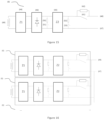
Figure 1 illustrates a charging equipment comprising an energy transmitter module (100) (TX) and an energy receiver module (101) (RX) according to an embodiment of the invention. -
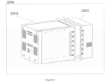
Figure 2 illustrates an AGV wireless charging system which comprises a TX module (200) which is called the charger module and an RX module (201) which is placed on the AGV according to an illustrative example not part of the claimed invention. -
Figure 3 illustrates the back and the front of an AGV RX receiver (300) module according to an illustrative example not part of the claimed invention. -
Figure 4 illustrates the back and the front of a transmitter module (400) according to an illustrative example not part of the claimed invention. -
Figure 5 illustrates a system comprising a primary (TX) coil and a secondary (RX) coil according to an illustrative example not part of the claimed invention. -
Figure 7 illustrates an RX module according to an embodiment of the invention. -
Figure 8 illustrates a TX transmitter module according to an illustrative example not part of the claimed invention. -
Figure 9 illustrates a near-field antenna according to an illustrative example not part of the claimed invention. -
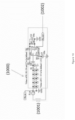
Figure 10 illustrates a near-field (NF) receiver circuit according to an illustrative example not part of the claimed invention. -
Figures 6 ,11 and12 illustrate further illustrative examples not part of the claimed invention. -
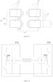
Figure 13 shows a schematic configuration of an embodiment of a wireless energy transfer station with two energy transmitting circuits (each having a coil) aligned with two energy receiving circuits (each having a coil) and electrically connected for charging an energy storage element. -
Figure 14 shows a schematic representation of an illustrative example not part of the claimed invention of (part of) a wireless energy transmitting circuit. -
Figure 15 shows a schematic representation of an embodiment of (part of) a wireless energy receiving circuit. -
Figure 16 shows a schematic representation of an embodiment of a wireless energy receiving system (with two energy receiving circuits), which system can be electrically connected to an energy storage element. -
Figure 17 shows a schematic representation of an alternate embodiment of a wireless energy receiving system (with two energy receiving circuits), which system can be electrically connected to an energy storage element. -
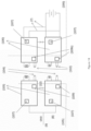
Figure 18 shows a schematic representation of an embodiment wherein an AGV comprises at least two energy receiving circuits, each with a controller and the energy transfer station comprises at least two energy transmitting circuits, each with a controller. - The charging equipment comprises an energy transmitter module (100) (TX) and an energy receiver module (101) (RX).
- The TX module (100) is connected to the grid or to a DC link voltage.
- The RX module (101) is connected to a battery. Optionally through a electronic converter.
- The RX box (101) has a Near Field (NF) transmitter (902) (110) sending an identification from AGV receiver module (101) to charger transmitter module (100) through an NF receiver (1000) (109). This identification might be and serial number, a wireless communication address, .... This information is communicated from (110) to (109).
- Receiving the magnetic near field on (109) shows that an AGV is present at the charge module and optionally it indicates that the AGV is aligned to the charger.
- Optional: In case the NF has a back channel communication too, the data communication can be 2 ways.
- After receiving sufficient information from the AGV, the wireless module (107) and (108) try to make connection. After making connection, a communication link is established between the AGV module and its charge module. In that case the NF is not needed any more and power transfer can be initiated.
- The AGV wireless charging system is built out of a TX module (200) which is called the charger module and a RX module (201) which is placed on the AGV. The primary TX module (200) contains in this case the wireless charging electronics.
- In the case presented in this figure, the TX coil is integrated in the wireless power TX module (200), but could be a lose part too, that could e.g. be mounted separately in the charging station or in the floor.
- In the case presented in this figure, the RX coil is integrated in the wireless power RX module (201) but could be a loose part too, that could e.g. be mounted separately in the AGV.
- The AGV RX receiver (300) module consists out of a front cover (310) being plastic to allow the magnetic field to come through. A shield back cover (305) closes the electronics housings and provides electromagnetic shielding. The AGV RX module (300) contains the RX receiver electronics. It has openings for (309) for air inlet and openings (307) for air outlet. The module has a connection for the output minus voltage and a connector (301) for the plus voltage output. Connector (301) allows communication busses (e.g. CAN) to connect to the AGV and to connect to parallel modules. Connector (302) provides user inputs and outputs.
- The flange (306) allows the RX part (300) to be integrated in an AGV.
- The transmit module (400) is composed out of the wireless charging electronics and the primary TX coil.
- The module has input power connectors (402) that can be fed at 3PH AC voltage or DC voltage.
- The module has a input connector (404) providing a connection for a communication bus to the charging station or industrial installation controller or to other modules (400).
- The transmitting coil is covered by a plastic front cover (411).
- The TX module has air inlet openings (401) and air outlets (406) for cooling purposes.
- Represents the build-up of the primary (TX) coil and the secondary (RX) coil. We call this the coupler (500) construction.
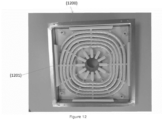
- The coupler construction comprises a shielding plate (504) that holds ferrite (502), plastic isolator and wire (
Figure 12 ) (1200). - TX coil and RX coil can have different ferrite construction, shield construction, plastic construction and different number of windings and different wire.
- Four areas (506) of ferrite in the TX coupler ensure that the magnetic field gets toward the four areas of ferrite in the RX coupler to avoid leakage field to the maximum.
- Four areas (506) of ferrite in the RX coupler ensure that the magnetic field gets toward the four areas of ferrite in the TX coupler to avoid leakage field to the maximum.
- In the middle, multiple ferrites (507) are providing a gateway for the magnetic flux from TX coil to RX coil and from RX to TX.
- The metal coil holder (504) holds ferrites (503) that provide a flux path for the magnetic field under the coil. On top of the ferrite (503), (506) and (507), a plastic part provides insulation between the holder (504), ferrite (503, 506 and 507) and the wire (1201).
- This plastic part has the following functions:
- 1. Insulation between wiring / electronics and housing. We assume that the housing of the TX is connected to the earth (PE) and that the housing of the RX module is connected to the BATTERY (102) GND or 0V or floating or to the casing (chassis) of the AGV. The plastic takes care about creepage distance and clearance according to the requirement of the applicable standards.
- 2. The plastic has also the function of as a coil former to hold the windings.
- 3. The plastic can be made out of multiple parts (4 in our case) to have smaller mould. Optional overlap can take care of electrical creepage and clearance.
- 4. The plastic can have break out areas to allow the wire to escape to the electronics that are mounted at the back.
- 5. The plastic can provide insulation in the openings that allow the wire go to the back.
- 6. The plastic can support the front cover (310) and (411).
- 7. The plastic can be made out of a material that can resist to higher temperatures.
- The ferrite at the sides (506) has similar height as the flange (504) so that the metal is saved from the major part of the magnetic field. If the ferrite would not be there or be lower that the flange, the eddy current losses in the flange would be high. So it has been found that at least equal ferrite height is required.
- The RX module (201) contains the RX (701) coil and the RX electronics (702) (703), (704), (705) and (706) and optionally (711) (712) OR (709) and (710).
- The RX module also contains a controller.
- The TX transmitter module (200) (400) contains electronics to drive the primary TX coil.(804) that is held into the primary coupler holder (500). This electronics receive a + (808) and - (809) from the input connector (402) or from and internal grid rectifier. (808) and (809) form a DC link that holds two halve bridges (805) and (806) forming together a full bridge inverter. The halve bridge point (802) is connected to an impedance Z towards the first TX coil (804) end. The other half bridge point (803) is connected to an impedance Z towards the second TX coil (804) end.
- The full bridge (805) - (806) will be switched as shown in
figure 6 , where (25) shows the voltage on (802) and (26) shows the voltage on (803). Each period (30), (31), ... represents the switching frequency. By keeping the switching pattern and in (25) and (26), the coil sees the differential voltage (27). Using the switching pattern (25) and (26), the switching losses can be equalised over both half bridges (802) and (803). - At position (501) a near field antenna is installed. In the RX the NF coil will act as a transmitter. In the TX the NF coil will act as a receiver.
- The transmitter NF coil (901) will be driven by an electronic circuit (902) with a frequency and on/off modulation or will be driven with frequencies and FSK modulation. The modulator circuit can be connected to the driver circuit (902) through signal (900).
- In the case the coil needs a higher voltage (1102) than available, the circuit (902) can be driven by a circuit (1100) that acts as a boost converter boosting an available voltage to a suitable voltage.
- A shut-down signal (1101) can be made available to shut off the NF transmitter (902).
- Contains an NF receiver circuit. The NF coil (1001) that is placed at position (505) receives the NF magnetic field signal from the transmitter coil (901) and filters this coil with a band pass filter. A comparator OP1 detects the signal and demodulates the signal to the signal (9002).
- The near field communication and coil setup has the following functions:
- Detecting alignment of (200) and (201) so that a decision can be made that wireless power transmission is possible.
- Detecting the distance between (200) and (201) so that a decision can be made that wireless power transmission is possible and safe.
- Sending identification data from AGV to Charger. In case a back channel is provided: information can be sent in the direction Charger to AGV.
- The concept is that way that the when the AGV arrives at the charging station, it sends out the identification information including its wireless address. Then the charger communicates further with the AGV.
- This wireless communication includes:
- Further exchange of information regarding the type of AGV receiver module and Charger transmitter module.
- Exchanging fault conditions in the electronics in AGV and Charger.
- Control loop information: de AGV RX module sends the output current information and the setpoint of the output current information to the Charger TX module. The charger TX module will then drive the full bridge (800) that way that the AGV module output current approaches the AGV module output set current.
- The present invention concerns a method and systems for wireless power transfer to electric vehicles, preferably AGVs.
- Unless otherwise defined, all terms used in disclosing the invention, including technical and scientific terms, have the meaning as commonly understood by one of ordinary skill in the art to which this invention belongs. By means of further guidance, term definitions are included to better appreciate the teaching of the present invention.
- As used herein, the following terms have the following meanings:
"A", "an", and "the" as used herein refers to both singular and plural referents unless the context clearly dictates otherwise. By way of example, "a compartment" refers to one or more than one compartment. - "Comprise", "comprising", and "comprises" and "comprised of" as used herein are synonymous with "include", "including", "includes" or "contain", "containing", "contains" and are inclusive or open-ended terms that specifies the presence of what follows e.g. component and do not exclude or preclude the presence of additional, non-recited components, features, element, members, steps, known in the art or disclosed therein.
- The term "energy storage element" refers generally to any element or component capable of rechargeable energy storage, thus comprising batteries . It furthermore is in not necessarily reduced to a single battery or energy storage element, but could also describe a battery pack which combines several separate batteries into a unit that allows to install said battery pack more easily, instead of installing the batteries separately. Furthermore, such a battery pack can be provided with extra features, for instance allowing data transfer (in one or both ways) between the battery pack and other systems, preferably the power transfer system of the invention.
- The term "wireless energy transfer station" or "charging station" refers to a system designed for inductively charging an energy storage element (or several) of an AGV. This can be achieved by a so-called charging post, where the separate energy transmitting circuits are stacked in a vertical plane, or a charging mat or floor, where the energy transmitting circuits are provided in a horizontal plane.
- The term "energy transmitting circuit" refers to a circuit designed to generate a magnetic field for power transfer with a coupling element, preferably with a coil.
- The term "energy receiving circuit" refers to a circuit designed to inductively couple to an energy transmitting circuit, and to generate an induced current from magnetic fields picked up by a coupling element, preferably a coil.
- The term "AGV" can refer to typical AGVs such as forklifts, but also to composite systems, wherein the composite system is built up from a number of AGVs and/or functional AGV slave modules, possibly detachable (cobots, tools, machinery, industrial robots, systems designed for a number of specific functions). The parts of the composite system can furthermore be equipped with a personal battery or batteries. For a further definition, reference is made to the European patent application with application number
EP16187684.2 - The recitation of numerical ranges by endpoints includes all numbers and fractions subsumed within that range, as well as the recited endpoints.
- Furthermore, note that in what follows, the energy transmitting/receiving circuits and the transmitting/receiving controllers are described as separate elements. While this is true, in reality the latter will typically be built into the former. As such, it is possible that the transmitting/receiving controllers are comprised in the energy transmitting/receiving circuits, although this is not necessarily the case.
- In a first aspect, the invention provides a method for wireless energy transfer from a wireless energy transfer station to an automated guided vehicle (AGV), whereby said wireless energy transfer station comprises two or more energy transmitting circuits, each preferably comprising a coil and a resonant capacitor, and whereby said AGV comprises at least one energy storage element, preferably a battery, and two or more energy receiving circuits, each preferably comprising a coil and a resonant capacitor, configured for wirelessly receiving energy from one of said energy transmitting circuits and configured for charging said at least one energy storage element with said wirelessly received energy, comprising the following steps:
- a. aligning two or more of said energy receiving circuits with an equal number of said energy transmitting circuits for inductive coupling, whereby said aligning is verified by near-field communication (NF), and optionally by a second wireless communication, between the AGV and the wireless energy transfer station, optionally by transmitting coordinates of the wireless energy transfer station to the AGV and more preferably by furthermore by the AGV determining an orientation of the AGV with respect to the wireless energy transfer station;
- b. inductively coupling said aligned energy transmitting circuits with said energy receiving circuits, wherein at least two of said energy transmitting circuits are inductively coupled with at least two of said energy receiving circuits in a one-on-one relation;
- c. transferring energy from said inductively coupled energy transmitting circuits to said inductively coupled energy receiving circuits by inducing a current in said energy receiving circuits;
- d. charging said at least one energy storage element with the transferred energy, wherein the induced current of each of said energy receiving circuits is provided in parallel with respect to each other to said at least one energy storage element.
- The proposed method remedies several of prior art shortcomings. One of those is the inability to efficiently provide energy at high rates (especially in providing high currents to the energy storage element) in order to fully charge an energy storage element rapidly. Currently this can only be achieved by using exorbitantly high currents in the charging station and thereby transferring great amounts of energy. However, by using such high levels of current, not only is a dangerous situation created (both for human operators as well as for the vehicles itself, as an accident can easily damage the subtle circuitry or could start a fire in case of short-circuiting. Furthermore, high currents typically lead to high losses (due to Joule effect amongst others) and require more specialized circuitry and components both on the transmission end (charging station) and the receiving end of the vehicle to cope with the high currents and voltages. The applicant succeeds in transferring energy at high rates by parallelizing several energy transfer modules on both sides. This allows the energy transmitting circuits of the wireless energy transfer station to operate at relatively low currents and voltages, but in combination, still transferring a substantially high amount of energy in a limited time. Consequently, this will allow the energy transfer to happen under much safer conditions with substantially lower energy losses. Furthermore, the circuitry used can be much cheaper since very few elements will have to be able to deal with high currents, not only saving costs in initial purchase but also in maintenance and replacements as elements dealing with high currents will typically break down more often, and when this occurs dangerous situations can likely ensue. In addition to this, the separate energy transferring circuits may be positioned and operationally synchronized in order to form a dipole or multipole, resulting in a reduced magnetic field in the surroundings. Note that the number of energy receiving circuits can be 2, 3, 4, 5, 6, 7, 8, 9, 10, 12, 15, 20 or more. The same applies for the number of energy transmitting circuits, however, these numbers need not be equal. The energy receiving circuits are preferably furthermore adapted to rectify the induced currents before providing them to the energy storage element, and can comprise a filter and/or a rectifier.
- Each of the transmitting circuits that actively participates in a power transfer, is inductively coupled with a receiving circuit and induces a current in said receiving circuit, again side current being relatively low and thus not requiring specialized components or causing undesirable losses. The currents of each of the receiving circuits in use are then provided in parallel with respect to each other, to the energy storage element. This is preferably the only part of the circuit where a high current is actually produced. By limiting the high current to this section and thus the need for higher quality components, the costs remain limited as well.
- Furthermore, the proposed method provides other advantages, such as a flexible way of transferring energy depending on the configuration of the receiving circuits of the AGV. The wireless energy transfer station can couple a desired amount of transmitting circuits depending on the number of receiving circuits (and/or the physical configuration thereof) to provide an optimal energy transfer. This match in transmitting and receiving circuits can be achieved in a number of ways, for instance by recognition (IR or others) by the separate circuits that their counterpart is well enough aligned for coupling, or can be by a transmission of information concerning the number and/or physical configuration (for instance, vertical stack, horizontal stack, ...) of the receiving circuits to the other side (side of the charging station), thus enabling the correct transmitting circuits to be used for the power transfer. Of course any other logical way of correctly aligning a correct number of circuits on both transmitting and receiving side is possible and are to be considered as part of the scope of the application. The use of several, separate inductive couplings between transmission and receiving circuits also allows the method to overcome possible mechanical or electronical defects, as the other 'modules' can take over and still charge the energy storage elements, though perhaps at a lowered efficiency, while this would necessitate immediate reparations in prior art systems.
- In an illustrative example not part of the claimed invention. the energy transmitting circuits are each separately controlled by a transmitting controller (and thus separately provided with one). Each of these transmitting controllers is configured to be able to control step c of the method, transferring energy from the energy transmitting circuit to the energy receiving circuit. This allows the charging station to overcome possible malfunction or problems in case only one central transmitting controller is used that directs all of the separate transmitting circuits. Furthermore, it allows a more complex control and the provision of a more performant, individual operation regime of the transmitting circuits themselves to optimize the energy transfer achieved.
- In an illustrative example not part of the claimed invention. the energy receiving circuits are each separately controlled by a receiving controller (and thus separately provided with a receiving controller). This will allow the separate energy receiving circuits to be able to carry out a wireless energy transfer, should one of said circuits or a sole receiving controller (controlling the entire receiving circuit) malfunction, or not be able to correctly align with an energy transmitting circuit, or should other problems arise. By separately controlling or driving the energy receiving controllers by their own receiving controller, this problematic situation is adverted, and furthermore, each energy receiving circuit can be individually optimized as the receiving controller can calibrate the operation regime of each energy receiving circuit separately.
- In an illustrative example not part of the claimed invention, the energy transmitting circuits are driven by two half bridges.
- In an illustrative example not part of the claimed invention. each of the energy transmitting circuits of the wireless energy transfer station comprises a separate, associated transmitting controller, whereby a master energy receiving circuit is appointed among one of the energy receiving circuits for directing (driving) the transmitting controllers and a master energy transmitting circuit.
- In an illustrative example not part of the claimed invention, the wireless energy transfer station and the AGV are adapted for wireless communication, preferably via near-field communication (NF) and optionally via a second wireless communication bus, said method further comprising the following steps:
- a. establishing a data connection via NF between the wireless energy transfer station and the AGV;
- b. exchanging AGV information from the AGV to the wireless energy transfer station, at least comprising the number of energy receiving circuits (in the AGV, or intended to be used in the AGV for the power transfer);
- c. inductively coupling a number of energy transferring circuits with said energy receiving circuits, wherein said number of energy transferring circuits are inductively coupled with the energy receiving circuits in a one-on-one relation;
- d. transferring energy from said inductively coupled energy transmitting circuits to said inductively coupled energy receiving circuits by inducing a current in said energy receiving circuits;
- A preferred embodiment is illustrated in
figure 18 . Herein: - Each RX module (also referred to as energy receiving circuit) (100) on the AGV (106) has a circuit (101) that generates a magnetic near field (NF) (102).
- Each TX module (also referred to as energy transmitting circuit) (103) on the charging station (105) has a magnetic near field receiver circuit (104).
- Each RX module (100) on the AGV (106) has a wireless communication circuit (107), e.g. Bluetooth.
- Each TX module (103) on the charging station (105) has a wireless communication circuit (107), e.g. Bluetooth.
- Upon arrival of an AGV to the charging station, the AGV sends a NF signal trough (101) to the charging station (105). This signal can optionally contain data information with the identifier of the AGV, with the address of the wireless communication device or a serial number as per examples.
- When the charging station has received such information, its wireless communication circuit (104) will make communication link to the wireless communication circuit (104) of the AGV.
- Each 'aligned module pair RX and TX' tries to make connection, by first sending the NF information from AGV to Charger station and consequently make a wireless connection.
- In case two of more paired modules have a proper connection through above procedure, the RX circuits can exchange the communicated information through there interconnection bus, e.g. a CAN bus. In this way, a system with two or more paired modules can continue operation with one wireless link only.
- The wireless link can also be a gateway for information receiving from the AGV customer interface (e.g. CAN) towards the charger stations' customer interface. This brings a free of charge (surplus) functionality available for to the customer.
- Each paired module exchanges independently energy from the charger circuit to the AGV receiver circuit. This exchange of energy is controlled by a controller (109, 109b) in each of the charger station transmitting circuits and AGV receiving circuits.
- It is possible for a customer to manually choose a master circuit (receiving and/or transmitting) on the AGV side and/or on the charging station side which controls the energy transfer between charging station and AGV. Alternatively, these are automatically chosen. Typically, the AGV will communicate a desired voltage setpoint and/or current setpoint (or power setpoint) to the charging station. This instruction is then divided by the master transmitting circuit over one or more of the energy transmitting circuits according to maximal power and/or current output per transmitting circuit. For instance, if an AGV with 3 receiving circuits requires a power supply of 250 W from a charging station with 5 transmitting circuits, a master transmitting circuit was appointed, which then divides the to be provided required power supply over 3 transmitting circuits of the charging station (evenly or not, depending on specific characteristics of the circuits - possibly as the circuits are configured for different power/current outputs to better suit variations in AGV power/current requirements for charging), which couple with 3 of the receiving circuits of the AGV. This is in practice accomplished by the master transmitting circuit controlling the operating current and voltage for each of the transmitting circuits that are used in the energy transfer.
- Each (two or more) aligned module pair(s) (charging station side transmitting circuit + AGV side receiving circuit) will individually work based on their own current setpoint, which is preferably set by a master circuit on one or both sides of the power transfer.
- As mentioned, one of the circuits in the charging station preferably operates as a master circuit and one of the circuits in the AGV can operate as a master circuit. The master circuit in the charging station has the responsibility to split the e.g. current setpoint for the charging operation between the different paired modules.
- In case during the charging process or outside the charging process, one charging station transmitting circuit fails, another transmitting circuit automatically takes over the function of master so that the charging can continue at possibly lower current.
- In case an output current setpoint is not used, but a battery charging current profile is used, the master can take care of organizing the other slave modules.
- At the charging station side, a master transmitting circuit and/or at the AGV receiver side, a master receiving circuit is appointed. This is possible since the energy transmitting controllers, which direct the transmitting circuits are linked by one or more communication interfaces. Alternatively or additionally, same applies to the energy receiving circuits and receiving controllers.
- The applicant has noted that the use of near-field communication is ideally suited for the purpose of communication between the charging station and the AGV. Other types of communication typically rely on optical connections, but optical connections can easily be disrupted or blocked. They are for instance very sensitive to dirt or dust that could block optical gates and thus disable connection. Since dust and dirt are very relevant in industrial conditions, such as in warehouses, factories and others, this is a very real problem. NF however does not need a direct visual line to communicate, and can be used even when the charging station is operational (and strong electromagnetic fields are present which could disrupt other conventional communication techniques), and furthermore allows bidirectional information exchange. Of course, alternatives are possible such as WiFi or others. The information to be exchanged can furthermore comprise a state of charge of the energy storage element, a desired (or required) output current setpoint (and/or power and/or voltage) and others. Communication may or may not continue during charging, for instance to indicate when the desired (required) current is not achieved on the receiving side so adjustments can be made on the side of the charging station (for instance more or less current, higher voltages, adjustment in alignment of AGV to charging station, load adjustments, ...). Due to the bidirectional nature of the information exchange, the charging station can also (repeatedly or periodically) supply to the AGV instructions to improve alignment (for instance changing distance and/or orientation of AGV with respect to the charging station) in order to optimize the coupling.
- Typically, a multitude or fleet of electric vehicles or AGVs are present in most situations (for instance factory work floor), and need to be controlled carefully in order to optimize charging (for instance through preventive charging of some vehicles to avoid conflict of too many vehicles needing charging at one point in time). These can be controlled from a central point, which assigns tasks to the separate vehicles and can obtain exact positions and orientations of the vehicles (with for instance individual digital addresses). This could allow the central point to also direct charging and specifically correct alignment of the vehicle, thereby ensuring correct alignment of (a part of) the energy receiving circuits with respect to (a part of) the energy transmitting circuits. Hereby it is implicitly assumed that the energy transferring and receiving circuits each have some kind of a coupling element, for instance a coil, that is used for (aligning and) inductively coupling with each other, and through which coupling energy is transferred. When suggesting that the energy receiving and/or transferring circuits can be displaced, this can of course mean that the coupling element is displaced as this is to be aligned for coupling, while the rest of the circuit can remain substantially in the same place. Most preferably, the energy transferring circuits (or parts thereof) are displaced, as this will reduce the necessity to enable such displacements on the AGV side and only requires this option in the charging station. While this can be controlled from the central point, the applicant notes that this can be augmented by further communication between the charging station and the vehicle or AGV, for instance through NF or a sensor that can detect sufficient alignment (which can in turn be provided back to the central point in order to adjust the position and/or orientation of the AGV).
- According to the invention, the AGV comprises at least one rectifier and at least one dump load, whereby each of the individual energy receiving circuits comprise at least one rectifier and at least one dump load, and the method further comprises the following steps:
- a. capturing and rectifying the induced currents of the energy transmitting circuits with said at least one rectifier, and providing the rectified currents to the energy storage element;
- b. limiting an output voltage on the energy receiving circuits by the at least one dump load in case of disconnection of the energy storage element and/or in case of detection of an overvoltage on the energy receiving circuits.
- By employing the abovementioned topology for manipulating the induced current, it is guaranteed that a desirable current is provided to the energy storage element under safe conditions, while only using relatively low current components which are less expensive and typically physically more robust (which can be convenient in industrial settings). According to the invention, a filter is be provided to further adjust the rectified current before providing it to the energy storage element.
- In an illustrative example not part of the claimed invention, the energy transferring circuits are configured to employ hard switching in certain operation points. The circuits can comprise silicon carbide power components and/or gallium nitride power components or others to reduce losses when operating under a hard switching pattern. Alternatively, the energy transferring circuits can be configured to be able to operate both under hard switching and under soft switching.
- According to the invention, the energy receiving circuits generate an output voltage that is placed over the energy storage element, whereby said output voltage is substantially equal to the normal voltage of the energy storage element plus the voltage drop over possible circuitry and cablings the energy storage element is possibly incorporated in. The output voltage in case of a so-called load dump (which may cause problems such as voltage spikes and damage to components) is limited by providing dump circuitry (for instance a resistor, varistor, TVS diodes, or others) to the energy receiving circuits (can be provided separately or for several of said energy receiving circuits). Said dump circuitry is designed to reduce or limit a voltage spike in case of a sudden disconnection (from the energy storage element). When the dump circuitry is activated (to be understood as that the output voltage is substantially placed over the dump circuitry (such as when the energy storage element is disconnected), a communication is done to the charging station (or to the energy transferring circuits) to stop the power transfer. Preferably, the dump circuitry is configured to withstand the output voltage during a short time (and to be able to dissipate the power from the energy receiving circuit or circuits), which short time is the time between detection of the load dump until the power transfer is stopped. Alternatively, there may be several dump circuitries present (for instance one for each energy receiving circuit), and a number of dumps is activated (for instance sequentially) accordingly as the power transfer necessitates. This may be accomplished by initially using a single dump circuitry. Should it be unable to dissipate all of the power generated by the energy receiving circuits, the output voltage will rise and a second dump circuitry can be used, doubling power dissipation possibilities, and so on.
- In a second aspect, the invention provides a wireless energy transfer station for wireless energy transfer from the wireless energy transfer station to automated guided vehicles (AGVs), whereby said AGVs comprise one or more energy storage elements and two or more energy receiving circuits, preferably comprising a coil and a resonant capacitor, configured for receiving energy through wireless energy transfer and configured for charging said energy storage element with said received energy, whereby the wireless energy transfer station comprises:
- a. two or more energy transmitting circuits, comprising a coil and a resonant capacitor, said energy transmitting circuits being configured for inductively coupling with one of the energy receiving circuits of the AGV in a one-on-one relation, and transmitting energy to said inductively coupled energy receiving circuit through wireless energy transfer, whereby said energy transmitting circuits are set-up in a physical configuration with respect to each other to match a physical configuration of the energy receiving circuits of the AGV; and
- b. two or more transmitting controllers, each associated to one of the transmitting circuits, configured to determine at least the number of energy receiving circuits comprised in the AGV, and each adapted to control the associated energy transmitting circuit;
- It is to be considered that the transmitting controllers will typically be built into or onto the energy transmitting circuit it is associated to (amongst others, to drive it more efficiently), so a transmitting controller is provided with each energy transmitting circuit. Furthermore, only energy transmitting circuits with a functioning transmitting controller will be allowed to inductively couple to an energy receiving circuit. A similar provision preferably applies to the energy receiving circuits and the receiving controllers.
- Preferably, the energy transmitting circuits are modular and can be removed from or more added to the wireless energy transfer station in order to satisfy requirements in output current. It is presumed that the energy transmitting circuits can be placed in such a way that they align with standard configurations of the energy receiving circuits on the AGV (for instance, distances between the separate energy receiving circuits). Alternatively, the wireless energy transfer station can displace (part of) the energy transmitting circuits (automatically) to better align with (part of) the energy receiving circuits. Again, the previous assertions apply concerning the specific structure of the circuits and that typically a certain part on each side will need to be aligned with respect to each other.
- Furthermore, many of the modifications proposed when discussing the method have also discussed structural changes, and as such said changes and modifications can be implemented to the wireless energy transfer station even if not explicitly discussed in what follows.
- The proposed charging station (or wireless energy transfer station) is ideally suited for executing the method of wireless energy transfer discussed in this document. Due to the incorporation of several 'parallelized' energy transferring circuits (typically comprising a coil for inductive coupling with a coil of the energy receiving circuit of the electric vehicle). As mentioned, in this way, a high current can be induced through energy storage element of the electric vehicle or AGV to achieve very fast charging, while only generating such a high current at the energy storage element, thereby saving costs and space (as components for conducting high currents typically require more safeguards and such).
- Typically, the charging station will comprise a plurality (2, 3, 4, 5, 6, 7, 8, 9, 10, 12, 15, 20 or more) of energy transmitting circuits. Preferably, the charging station can be designed to enable charging of several AGVs at once, for instance by having a plurality of energy transmitting circuits on a front side of the charging station, as well as on another side (back side for instance) of the charging station (and optionally on more sides), said sets of energy transmitting circuits being able to be controlled independently from each other, thereby allowing charging of two (or more) AGVs at once. By providing a plurality of energy transmitting circuits, the charging station can be adapted to couple with a wide variety of AGVs which can each have particular configurations of energy receiving circuits (number as well as physical configuration). As mentioned before, the energy transmitting circuits (or parts thereof, especially the coupling elements, preferably a coil) can be displaced with respect to the charging station to better align with the energy receiving circuit (or part thereof, the coupling elements and again preferably a coil), and thereby achieve a more efficient power transfer.
- In an illustrative example not part of the claimed invention, the transmitting controllers are adapted to, based on feedback it may receive from the AGV which is being charged, to adjust power provided to separate energy transmitting circuits in order to better attune the currents and voltages that are induced in the energy receiving circuits on each other, thereby creating a more stable charging current for the energy storage element. As mentioned, the feedback between charging station and AGV may happen through NF, but of course other options exist such as WiFi, and/or possibly through a central control point.
- In an illustrative example not part of the claimed invention, the energy transferring circuits are provided with power via three-phase electric power supply, or alternatively via two-phase electric power supply, or can further alternatively be fed via DC electric power supply, preferably through a pluggable connector.
- In an illustrative example not part of the claimed invention. at least one, preferably each of the transmitting controllers is configured to drive the energy transmitting circuits via two half bridges per transmitting controller.
- In an illustrative example not part of the claimed invention, the transmitting controllers are configured to drive the inductively coupled energy transmitting circuits at different frequencies. By operating the energy transmitting circuits on different frequencies, this allows an entirely independent operation of the energy transmitting circuits with respect to each other, and would prevent the malfunctioning of one of the energy transmitting circuits to affect the others. Furthermore, the different frequencies will provide a more equalized total output voltage provided by the energy transmitting circuits.
- In an illustrative example not part of the claimed invention. the wireless energy transfer station is configured for wireless communication from (and/or to) an AGV via a communications link, preferably via near-field communication (NF) and optionally a second wireless communication, and acquiring AGV information comprising the number of operational energy receiving circuits on the AGV, and whereby the transmitting controllers are configured to determine based on the AGV information which of the energy transmitting circuits are used in a wireless energy transfer to the AGV. As mentioned, NF is an ideal communication method for the application of this technology in industrial settings, where dirt and dust may hinder other communications. The use of AGV information, particularly the number of (operational) energy receiving circuits of the AGV, allows the charging station (transmitting controller) to control the energy transmitting circuits in order to preferably couple an energy transmitting circuit to each available (operational) energy receiving circuit (which would come down to providing power to the energy transmitting circuit for inductive power transfer to the energy receiving circuit). In a third aspect, the invention provides a wireless energy receiving system for charging at least a battery, of an AGV, whereby said wireless energy charging system is comprised in the AGV and electrically connected to said at least one battery the wireless energy receiving system comprising:
- a. two or more energy receiving circuits, comprising a coil and a resonant capacitor, each configured inductively coupling with an energy transmitting circuit, comprising a coil and a resonant capacitor, of a wireless energy transfer station in a one-on-one relation, and configured for receiving energy through wireless energy transfer from said inductively coupled energy transmitting circuit whereby a current is induced in the energy receiving circuit, and furthermore configured to charge said battery by providing the induced current of each of said energy receiving circuit in parallel to said at least one battery;
- b. and preferably two or more receiving controllers, each associated to one of the energy receiving circuits, each configured to control the energy receiving circuits.
- The system described above can be provided to one or more AGVs, of a fleet for instance, which then can charge in a wireless energy transfer station as described in this document, and/or according to the method discussed in the document. The advantages of the abovementioned charging station and wireless energy transfer method are thus clearly applicable to the wireless energy receiving system as well. As mentioned, by providing separate receiving controllers each assigned to one of the energy receiving circuits, the possible malfunctioning of a sole controller is averted, or in case of impossible linkup, or should other problems arise.
- In the preferred embodiment, the wireless energy receiving system comprises means for communicating with a wireless enerav transfer station. Said means are configured for connecting a controller unit (for instance an ECU or a battery management system (BMS) of the AGV) of the AGV to said wireless energy transfer station. This allows for the communication of information relevant to the energy transfer, for instance, the number of energy receiving circuits (operational) comprised in the wireless energy receiving system, the physical configuration thereof, other parameters, for instance desired output current, desired output voltage. Furthermore, feedback can be sent during the energy transfer, for instance indications whether or not a desired output current is achieved (and possibly the difference between actual and desired output current), or a desired output voltage (again, possibly with the difference between actual and desired output voltage), which the wireless energy transfer station can then use to adjust its operational parameters (ranging from frequency, switching patterns, voltages, currents, distance and/or orientation of AGV to charging station and others).
- In the preferred embodiment, the energy receiving circuits comprise a rectifier and one or more filters and dump circuits.
- The rectified currents are then provided to the energy storage element to charge this. There is no further DC-DC conversion, thus allowing for a limited size of the energy receiving circuits, and thus of the system. A rectifier and a filter and a dump circuit are provided for each energy receiving circuit, as in this way, these do not need to be able to withstand high currents (and are individually cheaper), and only in a limited circuitry connected to the energy storage element, a high current needs to be conducted, which can be compactly and efficiently shielded for safety.
- The invention is further described by the following non-limiting examples which further illustrate the invention, and are not intended to, nor should they be interpreted to, limit the scope of the invention.
- The present invention will be now described in more details, referring to examples that are not limitative.
- In
Figure 13 , a schematic representation is shown of a wireless energy transfer station (1), which comprises two energy transmitting circuits (5a, 5b), which in turn each comprise a coupling element, a coil (60) in this case. Furthermore, a wireless energy receiving system (2) is shown, which comprises two energy receiving circuits (6a, 6b), which in turn comprise a coupling element, a coil (49) in this case, as well, and is electrically connected to an energy storage element (7). Note that the number of circuits displayed (on each side) in the example is purely random, and possible more circuits can be present at any side (transmitting and/or receiving) but these are not participating in the power transfer at hand. Reasons for the non-participation can be various, ranging from defects, bad alignment, deliberate limitation of the induced current for charging the energy storage element (7), a surplus on circuits on one side (as there is normally a one-on-one coupling), .... The energy transmitting circuits (5a, 5b) can each comprise a transmitting controller (which may communicate with each other wired and/or wireless (12), and is visible as element 109a inFigure 18 ), said transmitting controllers being able to adapt the power provided by a power supply and determine the current and voltage provided to the coil (60). Alternatively, a single control unit can be provided between the power supply and the energy transmitting circuits (5a, 5b), and can separately control said energy transmitting circuits (5a, 5b). As can be seen inFigure 13 , the coils (60) of the energy transmitting circuits (5a, 5b) are aligned with the coils (49) of the energy receiving circuits (6a, 6b) for inductive coupling and wireless power transfer. The precise process of the inductive power transfer between the (primary) coils (60) and the (secondary) coils (49) will not be discussed in depth in this document, as this is simply the principle under which a transformer operates and should be considered as known by any expert in the field. As is known, an AC current through the coils (60) of the energy transmitting circuits (5a, 5b) will induce induced currents through the coils (49) of the energy receiving circuits (6a, 6b) (at least of those that are aligned with an energy transmitting circuit that is operational). These induced currents will then be provided to the energy storage element (7) in parallel with respect to each other, whereby the normal output voltage of the energy storage element (7) is upheld. As mentioned before, this can be ensured by adapting some parameters on the transmitting side (1) and/or on the receiving side (2). By parallelizing the multiple induced currents of the energy receiving circuits (5a, 5b), a high current can be provided to the energy storage element, but said high current is limited to only this section, which furthermore can be effectively shielded for safety reasons. - As mentioned before, the charging station (1) and the wireless energy receiving system (2) may be adapted to communicate with each other through a communication bus (10, 11). Preferably, this communication is effected through near-field communication (NF), and optionally through a second wireless communication.
-
Figure 14 shows a schematic embodiment of part of an energy transmitting circuit where an impedance (Z) is provided on each terminal of the coil (60), and where two half bridges (15, 16) further drive the voltage and current through the coil (60). -
Figures 15, 16 , and17 show schematic embodiments of (a substantial part of) one or more single energy receiving circuits. -
Figure 18 shows a more detailed representation of a wireless energy transfer station and energy receiving system.
Claims (12)
- A method for wireless energy transfer from a wireless energy transfer station to an automated guided vehicle, AGV, whereby said wireless energy transfer station comprises two or more energy transmitting circuits and whereby said AGV comprises at least one battery, and two or more energy receiving circuits, configured for wirelessly receiving energy from said energy transmitting circuits and configured for charging said at least one battery with said wirelessly received energy, wherein each energy receiving circuit is configured to generate an output voltage that is placed over the battery;whereby each energy receiving circuit has a coil, and a rectifier and a filter wherein said rectifier is configured to capture and rectify the induced current received by the energy receiving circuit from the energy transmitting circuit and providing the rectified current to the battery, andwherein said filter is configured to further adjust the rectified current before providing it to the battery; andeach energy receiving circuit comprising a protection circuit configured to protect the energy receiving circuit in case of disconnection of a previously connected battery said protection circuit being a dump circuitry configured to reduce or limit a voltage spike when the battery is disconnected by, upon activation of the dump circuitry, placing said output voltage substantially over the dump circuitry, and whereby upon activation of the dump load circuitry a communication is done to the energy transmitting circuits to stop the power transfer,the method comprising the following steps:a. aligning two or more of said energy receiving circuits with an equal number of said energy transmitting circuits for inductive coupling, whereby said aligning is verified by near-field communication (NF), between the AGV and the wireless energy transfer station;b. inductively coupling said aligned energy transmitting circuits with said energy receiving circuits, wherein at least two of said energy transmitting circuits are inductively coupled with at least two of said energy receiving circuits in a one-on-one relation;c. transferring energy from said inductively coupled energy transmitting circuits to said inductively coupled energy receiving circuits by inducing a current in said energy receiving circuits;d. charging said at least one battery with the transferred energy, wherein the induced current of each of said energy receiving circuits is provided in parallel with respect to each other to said at least one battery.
- The method according to the preceding claim 1, whereby the energy transmitting circuits are connected to a grid or DC power source or current source; and/or whereby said energy receiving circuits are adapted for connection to a battery.
- The method according to claim 1 or 2, whereby the energy transmitting circuits are connected in parallel to a grid or DC power source to form a higher power wireless power system.
- The method according to any one of the preceding claims 1 to 3, whereby the energy receiving circuits are connected in parallel to a battery to form a higher output power or current wireless receiver system.
- The method according to any one of the preceding claims 1 to 4, whereby the energy receiving circuits and the energy transmitting circuits each comprise a near field transmitter circuit mounted therein, which near field transmitter circuit is adapted to send information to the near field receiver in the energy transmitting circuits.
- The method according to the preceding claim 5, whereby said information comprises identification information on energy receiving circuits and/or energy transmitting circuits.
- The method according to any one of the preceding claims 5 or 6, whereby said near field transmitter circuit comprises a near field transmitter coil, said coil being driven by a half bridge electronic circuit, said half bridge electronic circuit using frequency shift keying.
- The method according to any one of the preceding claims 1 to 7, whereby the energy transmitting circuits comprise a near field receiver circuit which comprises a near field receiver coil.
- The method according to the preceding claim 8 whereby said near field receiver coil comprises a bandpass filter and comprises frequency shift keying detection electronics.
- The method according to any one of the preceding claims 1 to 9, whereby the energy transmitting circuits comprise electronics to drive a primary energy transmitter coil.
- The method according to any one of the preceding claims 1 to 10, whereby the energy transmitting circuits comprise at least 2 half bridges that form an inverter to drive the energy transmitting circuit coil, preferably the primary energy transmitter coil.
- The method according to any one of the preceding claims 1 to 11, whereby the wireless energy transmitting circuits comprise at least 2 half bridges consisting out of total 4 electronic switches which form an inverter to drive the energy transmitting circuit coil while the inverter has a switching pattern that equalizes switching losses in both half bridges.
Applications Claiming Priority (3)
| Application Number | Priority Date | Filing Date | Title |
|---|---|---|---|
| EP16193173 | 2016-10-10 | ||
| EP16193174 | 2016-10-10 | ||
| PCT/EP2017/075869 WO2018069356A1 (en) | 2016-10-10 | 2017-10-10 | Energy transmitter and receiver module |
Publications (3)
| Publication Number | Publication Date |
|---|---|
| EP3523156A1 EP3523156A1 (en) | 2019-08-14 |
| EP3523156C0 EP3523156C0 (en) | 2023-06-07 |
| EP3523156B1 true EP3523156B1 (en) | 2023-06-07 |
Family
ID=60202007
Family Applications (1)
| Application Number | Title | Priority Date | Filing Date |
|---|---|---|---|
| EP17793579.8A Active EP3523156B1 (en) | 2016-10-10 | 2017-10-10 | Energy transmitter and receiver module |
Country Status (5)
| Country | Link |
|---|---|
| US (1) | US11479122B2 (en) |
| EP (1) | EP3523156B1 (en) |
| ES (1) | ES2951667T3 (en) |
| HU (1) | HUE063206T2 (en) |
| WO (1) | WO2018069356A1 (en) |
Families Citing this family (6)
| Publication number | Priority date | Publication date | Assignee | Title |
|---|---|---|---|---|
| EP3591824A1 (en) * | 2018-07-02 | 2020-01-08 | Delta Electronics (Thailand) Public Co., Ltd. | Wireless power transfer |
| CN108847706A (en) * | 2018-09-03 | 2018-11-20 | 北京有感科技有限责任公司 | A kind of multi-frequency wireless charging device and its application |
| US11728691B2 (en) | 2020-05-26 | 2023-08-15 | Apple Inc. | Communication between devices in a wireless charging system |
| CN113725939B (en) | 2020-05-26 | 2024-09-06 | 苹果公司 | Communication between devices in a wireless charging system |
| CN114087534A (en) * | 2021-11-26 | 2022-02-25 | 国网山东省电力公司临沂供电公司 | Wireless control inflator for combined electrical apparatus |
| CN116545128B (en) * | 2023-06-15 | 2024-10-25 | 河海大学 | Underwater wireless energy low-energy consumption supplementing device applied to autonomous aircraft |
Citations (4)
| Publication number | Priority date | Publication date | Assignee | Title |
|---|---|---|---|---|
| US20120306433A1 (en) * | 2011-05-31 | 2012-12-06 | Nam Yun Kim | Wireless power transmission and charging system, and power control method of wireless power transmission and charging system |
| US20150274023A1 (en) * | 2012-10-01 | 2015-10-01 | Renault S.A.S | Contactless charging system for charging a motor vehicle battery |
| US20160043565A1 (en) * | 2013-03-29 | 2016-02-11 | Panasonic Intellectual Property Management Co., Ltd. | Electricity supply device and electricity reception device |
| US20160075239A1 (en) * | 2014-09-16 | 2016-03-17 | Qualcomm Incorporated | Methods and systems for compatible operation between a wireless power transfer system and vehicle remote entry systems |
Family Cites Families (11)
| Publication number | Priority date | Publication date | Assignee | Title |
|---|---|---|---|---|
| US5237492A (en) * | 1992-06-23 | 1993-08-17 | The University Of Toledo | AC to DC converter system with ripple feedback circuit |
| US7561394B2 (en) * | 2007-12-10 | 2009-07-14 | Visteon Global Technologies, Inc. | System and method for overvoltage protection |
| JP5238420B2 (en) * | 2008-09-11 | 2013-07-17 | 矢崎総業株式会社 | Wireless charging system for vehicles |
| EP2375534A1 (en) * | 2010-04-09 | 2011-10-12 | Nxp B.V. | Apparatus for transferring energy to an accumulator and system for charging an electric accumulator |
| CN102947124B (en) | 2010-05-19 | 2017-02-08 | 高通股份有限公司 | Adaptive wireless energy transfer system |
| KR20120135885A (en) * | 2011-06-07 | 2012-12-17 | 삼성전자주식회사 | Wireless power transmitting/receiving system comprising transmitter and receiver, two-way communication method between the transmitter and the receiver, and the apparatuses |
| US20160176302A1 (en) | 2011-08-06 | 2016-06-23 | Delphi Technologies, Inc. | Interconnected wireless battery charging and regenerative braking systems for an electric vehicle |
| WO2013112609A1 (en) | 2012-01-23 | 2013-08-01 | Utah State University | Switch wear leveling |
| EP2928038A1 (en) * | 2014-03-31 | 2015-10-07 | ABB Technology AG | Inductive power transfer system and method for operating an inductive power transfer system |
| US10414279B2 (en) * | 2014-12-19 | 2019-09-17 | Ford Global Technologies, Llc | Inductive wireless power transfer systems |
| US10680457B2 (en) * | 2015-07-27 | 2020-06-09 | Witricity Corporation | Systems, methods, and apparatus implementing hybrid symmetric and asymmetric control for soft switching in wireless power transfer applications |
-
2017
- 2017-10-10 US US16/340,884 patent/US11479122B2/en active Active
- 2017-10-10 HU HUE17793579A patent/HUE063206T2/en unknown
- 2017-10-10 WO PCT/EP2017/075869 patent/WO2018069356A1/en not_active Ceased
- 2017-10-10 ES ES17793579T patent/ES2951667T3/en active Active
- 2017-10-10 EP EP17793579.8A patent/EP3523156B1/en active Active
Patent Citations (4)
| Publication number | Priority date | Publication date | Assignee | Title |
|---|---|---|---|---|
| US20120306433A1 (en) * | 2011-05-31 | 2012-12-06 | Nam Yun Kim | Wireless power transmission and charging system, and power control method of wireless power transmission and charging system |
| US20150274023A1 (en) * | 2012-10-01 | 2015-10-01 | Renault S.A.S | Contactless charging system for charging a motor vehicle battery |
| US20160043565A1 (en) * | 2013-03-29 | 2016-02-11 | Panasonic Intellectual Property Management Co., Ltd. | Electricity supply device and electricity reception device |
| US20160075239A1 (en) * | 2014-09-16 | 2016-03-17 | Qualcomm Incorporated | Methods and systems for compatible operation between a wireless power transfer system and vehicle remote entry systems |
Also Published As
| Publication number | Publication date |
|---|---|
| EP3523156C0 (en) | 2023-06-07 |
| US20190232808A1 (en) | 2019-08-01 |
| EP3523156A1 (en) | 2019-08-14 |
| ES2951667T3 (en) | 2023-10-24 |
| HUE063206T2 (en) | 2024-01-28 |
| US11479122B2 (en) | 2022-10-25 |
| WO2018069356A1 (en) | 2018-04-19 |
Similar Documents
| Publication | Publication Date | Title |
|---|---|---|
| EP3523156B1 (en) | Energy transmitter and receiver module | |
| US12151578B2 (en) | Device and method for charging electric vehicle with different charging standards | |
| JP6835802B2 (en) | Vehicle wireless power transmitters and receivers | |
| JP7308310B2 (en) | Wireless charging device, automatic matching method and charging dock | |
| KR101764496B1 (en) | Active rectifier for wireless power transfer system and vehicle assembly using same and operating method thereof | |
| JP6152960B2 (en) | Non-contact power transmission apparatus and non-contact power transmission method | |
| US10640001B2 (en) | Wireless power transfer method using field winding and vehicle assembly and electric vehicle using the same | |
| JP5942837B2 (en) | Relay machine, connector device, charging cable and power supply system | |
| EP3487030A1 (en) | Output device for wireless charging | |
| US20240186837A1 (en) | Wireless power transmission apparatus with multiple primary coils and adjacent coil muting | |
| CN111108016A (en) | Hybrid charging system | |
| EP3658406A1 (en) | Wireless charging system | |
| CN111247025A (en) | Charging device and system for transferring energy to mobile devices with accumulators and secondary windings | |
| CN104578349A (en) | Wireless charger and wireless charging system | |
| CN112075010B (en) | Wireless power transmission system for electric vehicle | |
| CN210780235U (en) | Wireless charging system for lighting device | |
| CN213594105U (en) | Wireless power supply system and stereo garage | |
| CN209233566U (en) | A kind of multi-coil wireless charging device | |
| KR20250139757A (en) | Charger and coil structure having a transmitting coil structure that performs phase correction in a phase aligned with the receiving coil when a misalignment with the receiving coil occurs | |
| TW202614465A (en) | Multiple power-format rechargeable battery and method of use | |
| CN117615935A (en) | Control method and power supply device for opening and closing electric vehicle charging door/port | |
| WO2013094721A1 (en) | Feeding apparatus and communication method | |
| JP2013183472A (en) | Power supply device and communication method | |
| JP2013183473A (en) | Power supply device and communication method |
Legal Events
| Date | Code | Title | Description |
|---|---|---|---|
| STAA | Information on the status of an ep patent application or granted ep patent |
Free format text: STATUS: UNKNOWN |
|
| STAA | Information on the status of an ep patent application or granted ep patent |
Free format text: STATUS: THE INTERNATIONAL PUBLICATION HAS BEEN MADE |
|
| PUAI | Public reference made under article 153(3) epc to a published international application that has entered the european phase |
Free format text: ORIGINAL CODE: 0009012 |
|
| STAA | Information on the status of an ep patent application or granted ep patent |
Free format text: STATUS: REQUEST FOR EXAMINATION WAS MADE |
|
| 17P | Request for examination filed |
Effective date: 20190508 |
|
| AK | Designated contracting states |
Kind code of ref document: A1 Designated state(s): AL AT BE BG CH CY CZ DE DK EE ES FI FR GB GR HR HU IE IS IT LI LT LU LV MC MK MT NL NO PL PT RO RS SE SI SK SM TR |
|
| AX | Request for extension of the european patent |
Extension state: BA ME |
|
| DAV | Request for validation of the european patent (deleted) | ||
| DAX | Request for extension of the european patent (deleted) | ||
| STAA | Information on the status of an ep patent application or granted ep patent |
Free format text: STATUS: EXAMINATION IS IN PROGRESS |
|
| 17Q | First examination report despatched |
Effective date: 20210211 |
|
| RAP3 | Party data changed (applicant data changed or rights of an application transferred) |
Owner name: IN2POWER NV |
|
| REG | Reference to a national code |
Ref country code: DE Ref legal event code: R079 Ref document number: 602017069743 Country of ref document: DE Free format text: PREVIOUS MAIN CLASS: B60L0011180000 Ipc: B60L0053120000 |
|
| RIC1 | Information provided on ipc code assigned before grant |
Ipc: B60L 53/12 20190101AFI20221020BHEP |
|
| GRAP | Despatch of communication of intention to grant a patent |
Free format text: ORIGINAL CODE: EPIDOSNIGR1 |
|
| STAA | Information on the status of an ep patent application or granted ep patent |
Free format text: STATUS: GRANT OF PATENT IS INTENDED |
|
| INTG | Intention to grant announced |
Effective date: 20221215 |
|
| GRAS | Grant fee paid |
Free format text: ORIGINAL CODE: EPIDOSNIGR3 |
|
| GRAA | (expected) grant |
Free format text: ORIGINAL CODE: 0009210 |
|
| STAA | Information on the status of an ep patent application or granted ep patent |
Free format text: STATUS: THE PATENT HAS BEEN GRANTED |
|
| AK | Designated contracting states |
Kind code of ref document: B1 Designated state(s): AL AT BE BG CH CY CZ DE DK EE ES FI FR GB GR HR HU IE IS IT LI LT LU LV MC MK MT NL NO PL PT RO RS SE SI SK SM TR |
|
| REG | Reference to a national code |
Ref country code: GB Ref legal event code: FG4D |
|
| REG | Reference to a national code |
Ref country code: CH Ref legal event code: EP Ref country code: AT Ref legal event code: REF Ref document number: 1574015 Country of ref document: AT Kind code of ref document: T Effective date: 20230615 |
|
| REG | Reference to a national code |
Ref country code: DE Ref legal event code: R096 Ref document number: 602017069743 Country of ref document: DE |
|
| U01 | Request for unitary effect filed |
Effective date: 20230630 |
|
| U07 | Unitary effect registered |
Designated state(s): AT BE BG DE DK EE FI FR IT LT LU LV MT NL PT SE SI Effective date: 20230705 |
|
| REG | Reference to a national code |
Ref country code: NO Ref legal event code: T2 Effective date: 20230607 |
|
| REG | Reference to a national code |
Ref country code: LT Ref legal event code: MG9D |
|
| REG | Reference to a national code |
Ref country code: ES Ref legal event code: FG2A Ref document number: 2951667 Country of ref document: ES Kind code of ref document: T3 Effective date: 20231024 |
|
| U20 | Renewal fee for the european patent with unitary effect paid |
Year of fee payment: 7 Effective date: 20231024 |
|
| PG25 | Lapsed in a contracting state [announced via postgrant information from national office to epo] |
Ref country code: RS Free format text: LAPSE BECAUSE OF FAILURE TO SUBMIT A TRANSLATION OF THE DESCRIPTION OR TO PAY THE FEE WITHIN THE PRESCRIBED TIME-LIMIT Effective date: 20230607 Ref country code: HR Free format text: LAPSE BECAUSE OF FAILURE TO SUBMIT A TRANSLATION OF THE DESCRIPTION OR TO PAY THE FEE WITHIN THE PRESCRIBED TIME-LIMIT Effective date: 20230607 Ref country code: GR Free format text: LAPSE BECAUSE OF FAILURE TO SUBMIT A TRANSLATION OF THE DESCRIPTION OR TO PAY THE FEE WITHIN THE PRESCRIBED TIME-LIMIT Effective date: 20230908 |
|
| PG25 | Lapsed in a contracting state [announced via postgrant information from national office to epo] |
Ref country code: SK Free format text: LAPSE BECAUSE OF FAILURE TO SUBMIT A TRANSLATION OF THE DESCRIPTION OR TO PAY THE FEE WITHIN THE PRESCRIBED TIME-LIMIT Effective date: 20230607 |
|
| PG25 | Lapsed in a contracting state [announced via postgrant information from national office to epo] |
Ref country code: IS Free format text: LAPSE BECAUSE OF FAILURE TO SUBMIT A TRANSLATION OF THE DESCRIPTION OR TO PAY THE FEE WITHIN THE PRESCRIBED TIME-LIMIT Effective date: 20231007 |
|
| REG | Reference to a national code |
Ref country code: HU Ref legal event code: AG4A Ref document number: E063206 Country of ref document: HU |
|
| PG25 | Lapsed in a contracting state [announced via postgrant information from national office to epo] |
Ref country code: SM Free format text: LAPSE BECAUSE OF FAILURE TO SUBMIT A TRANSLATION OF THE DESCRIPTION OR TO PAY THE FEE WITHIN THE PRESCRIBED TIME-LIMIT Effective date: 20230607 Ref country code: SK Free format text: LAPSE BECAUSE OF FAILURE TO SUBMIT A TRANSLATION OF THE DESCRIPTION OR TO PAY THE FEE WITHIN THE PRESCRIBED TIME-LIMIT Effective date: 20230607 Ref country code: RO Free format text: LAPSE BECAUSE OF FAILURE TO SUBMIT A TRANSLATION OF THE DESCRIPTION OR TO PAY THE FEE WITHIN THE PRESCRIBED TIME-LIMIT Effective date: 20230607 Ref country code: IS Free format text: LAPSE BECAUSE OF FAILURE TO SUBMIT A TRANSLATION OF THE DESCRIPTION OR TO PAY THE FEE WITHIN THE PRESCRIBED TIME-LIMIT Effective date: 20231007 Ref country code: CZ Free format text: LAPSE BECAUSE OF FAILURE TO SUBMIT A TRANSLATION OF THE DESCRIPTION OR TO PAY THE FEE WITHIN THE PRESCRIBED TIME-LIMIT Effective date: 20230607 |
|
| PG25 | Lapsed in a contracting state [announced via postgrant information from national office to epo] |
Ref country code: PL Free format text: LAPSE BECAUSE OF FAILURE TO SUBMIT A TRANSLATION OF THE DESCRIPTION OR TO PAY THE FEE WITHIN THE PRESCRIBED TIME-LIMIT Effective date: 20230607 |
|
| REG | Reference to a national code |
Ref country code: DE Ref legal event code: R097 Ref document number: 602017069743 Country of ref document: DE |
|
| PLBE | No opposition filed within time limit |
Free format text: ORIGINAL CODE: 0009261 |
|
| STAA | Information on the status of an ep patent application or granted ep patent |
Free format text: STATUS: NO OPPOSITION FILED WITHIN TIME LIMIT |
|
| 26N | No opposition filed |
Effective date: 20240308 |
|
| PG25 | Lapsed in a contracting state [announced via postgrant information from national office to epo] |
Ref country code: MC Free format text: LAPSE BECAUSE OF FAILURE TO SUBMIT A TRANSLATION OF THE DESCRIPTION OR TO PAY THE FEE WITHIN THE PRESCRIBED TIME-LIMIT Effective date: 20230607 |
|
| REG | Reference to a national code |
Ref country code: CH Ref legal event code: PL |
|
| PG25 | Lapsed in a contracting state [announced via postgrant information from national office to epo] |
Ref country code: CH Free format text: LAPSE BECAUSE OF NON-PAYMENT OF DUE FEES Effective date: 20231031 |
|
| PG25 | Lapsed in a contracting state [announced via postgrant information from national office to epo] |
Ref country code: CH Free format text: LAPSE BECAUSE OF NON-PAYMENT OF DUE FEES Effective date: 20231031 |
|
| U20 | Renewal fee for the european patent with unitary effect paid |
Year of fee payment: 8 Effective date: 20241025 |
|
| PG25 | Lapsed in a contracting state [announced via postgrant information from national office to epo] |
Ref country code: CY Free format text: LAPSE BECAUSE OF FAILURE TO SUBMIT A TRANSLATION OF THE DESCRIPTION OR TO PAY THE FEE WITHIN THE PRESCRIBED TIME-LIMIT; INVALID AB INITIO Effective date: 20171010 |
|
| PGFP | Annual fee paid to national office [announced via postgrant information from national office to epo] |
Ref country code: HU Payment date: 20251027 Year of fee payment: 9 |
|
| U20 | Renewal fee for the european patent with unitary effect paid |
Year of fee payment: 9 Effective date: 20251028 |
|
| PGFP | Annual fee paid to national office [announced via postgrant information from national office to epo] |
Ref country code: GB Payment date: 20251022 Year of fee payment: 9 |
|
| PGFP | Annual fee paid to national office [announced via postgrant information from national office to epo] |
Ref country code: NO Payment date: 20251024 Year of fee payment: 9 |
|
| PGFP | Annual fee paid to national office [announced via postgrant information from national office to epo] |
Ref country code: TR Payment date: 20251006 Year of fee payment: 9 |
|
| PGFP | Annual fee paid to national office [announced via postgrant information from national office to epo] |
Ref country code: IE Payment date: 20251024 Year of fee payment: 9 |
|
| PGFP | Annual fee paid to national office [announced via postgrant information from national office to epo] |
Ref country code: ES Payment date: 20251216 Year of fee payment: 9 |