EP3522783B1 - Device, system and method for calibrating a non-invasive health monitoring device - Google Patents
Device, system and method for calibrating a non-invasive health monitoring device Download PDFInfo
- Publication number
- EP3522783B1 EP3522783B1 EP17857972.8A EP17857972A EP3522783B1 EP 3522783 B1 EP3522783 B1 EP 3522783B1 EP 17857972 A EP17857972 A EP 17857972A EP 3522783 B1 EP3522783 B1 EP 3522783B1
- Authority
- EP
- European Patent Office
- Prior art keywords
- calibrating
- layer
- skin
- concentration
- specific
- Prior art date
- Legal status (The legal status is an assumption and is not a legal conclusion. Google has not performed a legal analysis and makes no representation as to the accuracy of the status listed.)
- Active
Links
Images

Classifications
-
- A—HUMAN NECESSITIES
- A61—MEDICAL OR VETERINARY SCIENCE; HYGIENE
- A61B—DIAGNOSIS; SURGERY; IDENTIFICATION
- A61B5/00—Measuring for diagnostic purposes; Identification of persons
- A61B5/145—Measuring characteristics of blood in vivo, e.g. gas concentration or pH-value ; Measuring characteristics of body fluids or tissues, e.g. interstitial fluid or cerebral tissue
- A61B5/14546—Measuring characteristics of blood in vivo, e.g. gas concentration or pH-value ; Measuring characteristics of body fluids or tissues, e.g. interstitial fluid or cerebral tissue for measuring analytes not otherwise provided for, e.g. ions, cytochromes
-
- A—HUMAN NECESSITIES
- A61—MEDICAL OR VETERINARY SCIENCE; HYGIENE
- A61B—DIAGNOSIS; SURGERY; IDENTIFICATION
- A61B5/00—Measuring for diagnostic purposes; Identification of persons
- A61B5/145—Measuring characteristics of blood in vivo, e.g. gas concentration or pH-value ; Measuring characteristics of body fluids or tissues, e.g. interstitial fluid or cerebral tissue
- A61B5/1455—Measuring characteristics of blood in vivo, e.g. gas concentration or pH-value ; Measuring characteristics of body fluids or tissues, e.g. interstitial fluid or cerebral tissue using optical sensors, e.g. spectral photometrical oximeters
-
- A—HUMAN NECESSITIES
- A61—MEDICAL OR VETERINARY SCIENCE; HYGIENE
- A61B—DIAGNOSIS; SURGERY; IDENTIFICATION
- A61B5/00—Measuring for diagnostic purposes; Identification of persons
- A61B5/145—Measuring characteristics of blood in vivo, e.g. gas concentration or pH-value ; Measuring characteristics of body fluids or tissues, e.g. interstitial fluid or cerebral tissue
- A61B5/1495—Calibrating or testing of in-vivo probes
-
- G—PHYSICS
- G01—MEASURING; TESTING
- G01N—INVESTIGATING OR ANALYSING MATERIALS BY DETERMINING THEIR CHEMICAL OR PHYSICAL PROPERTIES
- G01N21/00—Investigating or analysing materials by the use of optical means, i.e. using sub-millimetre waves, infrared, visible or ultraviolet light
- G01N21/17—Systems in which incident light is modified in accordance with the properties of the material investigated
- G01N21/25—Colour; Spectral properties, i.e. comparison of effect of material on the light at two or more different wavelengths or wavelength bands
- G01N21/27—Colour; Spectral properties, i.e. comparison of effect of material on the light at two or more different wavelengths or wavelength bands using photo-electric detection ; circuits for computing concentration
- G01N21/274—Calibration, base line adjustment, drift correction
-
- G—PHYSICS
- G01—MEASURING; TESTING
- G01N—INVESTIGATING OR ANALYSING MATERIALS BY DETERMINING THEIR CHEMICAL OR PHYSICAL PROPERTIES
- G01N21/00—Investigating or analysing materials by the use of optical means, i.e. using sub-millimetre waves, infrared, visible or ultraviolet light
- G01N21/17—Systems in which incident light is modified in accordance with the properties of the material investigated
- G01N21/47—Scattering, i.e. diffuse reflection
- G01N21/4785—Standardising light scatter apparatus; Standards therefor
-
- A—HUMAN NECESSITIES
- A61—MEDICAL OR VETERINARY SCIENCE; HYGIENE
- A61B—DIAGNOSIS; SURGERY; IDENTIFICATION
- A61B5/00—Measuring for diagnostic purposes; Identification of persons
- A61B5/145—Measuring characteristics of blood in vivo, e.g. gas concentration or pH-value ; Measuring characteristics of body fluids or tissues, e.g. interstitial fluid or cerebral tissue
- A61B5/14532—Measuring characteristics of blood in vivo, e.g. gas concentration or pH-value ; Measuring characteristics of body fluids or tissues, e.g. interstitial fluid or cerebral tissue for measuring glucose, e.g. by tissue impedance measurement
Definitions
- Noninvasive blood test measurements are the future of blood measurements. They are simple, harmless, unpainful and do not involve laboratory time. Several commercial products for noninvasive measurements are available today. However, for these devices to work properly they must be accurately calibrated to suit specific patients.
- Noninvasive blood test measurements are performed by attaching a measurement device to the patient's skin. These devices are usually operated by sending electromagnetic signals (e.g., visual light, IR radiation, RF radiation, etc.) via the patient skin targeting a blood vessel and reading reflection received from the blood vessel.
- electromagnetic signals e.g., visual light, IR radiation, RF radiation, etc.
- Different humans' skin has different characteristics, such as, different thicknesses of different skin layers, different amount of hair, different amount of pigment etc., and therefore may absorb differently the electromagnetic signals sent from the noninvasive measurements device. Accordingly, there is a need for a noninvasive blood measurement deceive that may be calibrated specifically to each user so to measure accurately, concentrations of various materials in the blood for patients with different skin characteristics and different anatomy.
- US2010042348 provides a method of calibrating an optical analysis system that makes use of multivariate optical signal analysis allowing to realize cost-efficient and robust implementation of a spectral analysis of an optical signal.
- the calibration method makes use of determining a parameter of a reference sample by means of the optical analysis system and comparing the actually determined parameter with a reference parameter that represents a precise and real property of the reference sample. Based on this comparison a calibration value can be determined that is applicable to perform a calibration of the optical analysis system with respect to at least one compound or analyte of the reference sample.
- Parameters and reference parameters of a reference sample may refer to a concentration of an analyte dissolved in the sample, or to spectroscopic background signals that have to be taken into account when performing a spectral analysis based on optical signals obtained from the reference sample.
- Various different reference samples providing a reference with respect to different acquisition conditions and different analyte or compound concentrations can be universally used.
- Analyte-specific reference data is preferably stored in a calibration unit of the optical analysis system and allows a high degree of automation of the calibration process.
- Some aspects of the invention are directed to a system for calibrating a device for measuring materials concentration in the blood.
- the system includes at least two sets of calibrating elements, each set comprising a plurality of calibrating elements.
- Each of the calibrating elements includes, a first layer simulating a specific human skin characteristics; a second layer comprising a specific concentration of one or more materials in the blood; and a third layer for simulating illumination reflection from a blood vessel in a skin tissue.
- the specific human skin characteristics comprise at least one of: skin thickness, skin color, skin hair density, skin tone, skin temperature, skin optical properties and skin hair color. All calibrating elements in a set the first layer may be the same first layer simulating the same specific human skin characteristics such that each set of calibrating elements simulate different specific human skin characteristics.
- Each calibrating element in a set of calibrating elements includes a different second layer comprising a different concentration of the one or more material.
- the third layer isolates the calibrating element from noise and reflections not related to the measured one or more materials in the second layer.
- the system further includes a controller that is configured to: receive illumination intensities from the device for measuring materials concentration when the device is attached to each calibrating element of the system; associate the received illumination intensities with the specific human skin characteristics and the specific concentration of the calibrating element to which the device is attached; and save the illumination intensities associated with the specific human skin characteristics and the specific concentration in lookup tables in a memory of the device for measuring materials concentration.
- the received illumination intensities may include illumination intensities at various wavelengths and the saved lookup tables include lookup tables for illumination intensities of a specific wavelength associated with the specific human skin characteristics, the one or more materials and the specific concentration.
- the system may further include a third layer for simulating illumination reflection from a blood vessel in a skin tissue.
- An additional aspect of the present invention is related to a method of calibrating a device for measuring materials concentration in the blood.
- the method includes: attaching the device for measuring materials concentration to each calibrating element included in one of two or more sets of calibrating elements.
- Each of the calibrating elements includes: a first layer simulating specific human skin characteristics; a second layer comprising a specific concentration of one or more materials in the blood; and a third layer for simulating illumination reflection from a blood vessel in a skin tissue.
- the specific human skin characteristics comprise at least one of: skin thickness, skin color, skin hair density, skin tone, skin temperature, skin optical properties and skin hair color.
- the first layer is the same first layer simulating the same specific human skin characteristic and each set of calibrating elements simulates different specific human skin characteristics, each calibrating element in a set of calibrating elements includes a different second layer comprising a different concentration of the one or more materials, and the third layer isolates the calibrating element from noise and reflections not related to the measured one or more materials in the second layer.
- the method further includes: receiving, by a controller of a calibrating system, illumination intensities from the device for measuring materials concentration when the device is attached to each calibrating element; associating, by the controller, the received illumination intensities with the specific human skin characteristics and the specific concentration of the one or more materials in the second layer of the calibrating element to which the device is attached; and recording, by the controller, the illumination intensities associated with the specific human skin characteristics and the specific concentrations in a memory of the device for measuring materials concentration.
- receiving illumination intensities may include receiving illumination intensities at various wavelengths and recording the illumination intensities may include creating lookup tables for illumination intensities of a specific wavelength associated with the specific human skin characteristic and the specific concentration.
- the terms “plurality” and “a plurality” as used herein may include, for example, “multiple” or “two or more”.
- the terms “plurality” or “a plurality” may be used throughout the specification to describe two or more components, devices, elements, units, parameters, or the like.
- the term set when used herein may include one or more items.
- the method embodiments described herein are not constrained to a particular order or sequence. Additionally, some of the described method embodiments or elements thereof can occur or be performed simultaneously, at the same point in time, or concurrently.
- System 100 includes at least two sets 105 and 106 of calibrating elements 105a-105d and 106a-106d. In some embodiments, system 100 may include additional sets, for example, set 107, of calibrating elements 107a-107d. A detailed description of a calibrating element is given with respect to Fig. 3 .
- System 100 further includes a controller 110, and may include a storage unit 120 a user interface 130 and a communication unit 140. Communication unit 140 may be configured to send and receive information from a device 10 for measuring materials concentration in the blood.
- controller 110 may include a processor 112 that may be, for example, a central processing unit (CPU), a chip or any suitable computing or computational device, an operating system 114 and a memory 116.
- System 100 may include a desktop computer, laptop commuter, a tablet, a mainframe computer or the like.
- Processor 112 may be configured to carry out methods according to embodiments of the present invention by for example executing instructions stored in a memory such as memory 116.
- Operating system 114 may be or may include any code segment designed and/or configured to perform tasks involving coordination, scheduling, arbitration, supervising, controlling or otherwise managing operation of controller 110, for example, scheduling execution of programs. Operating system 114 may be a commercial operating system.
- Memory 116 may be or may include, for example, a Random Access Memory (RAM), a read only memory (ROM), a Dynamic RAM (DRAM), a Synchronous DRAM (SD-RAM), a double data rate (DDR) memory chip, a Flash memory, a volatile memory, a non-volatile memory, a cache memory, a buffer, a short term memory unit, a long term memory unit, or other suitable memory units or storage units.
- Memory 116 may be or may include a plurality of, possibly different memory units.
- Memory 116 may store any executable code, e.g., an application, a program, a process, task or script.
- the executable code may include codes for calibrating a device for measuring materials concentration in the blood or any other codes or instruction for executing methods according to embodiments of the present invention.
- the executable code may be executed by processor 112 possibly under control of operating system 114.
- Storage 120 may be or may include, for example, a hard disk drive, a floppy disk drive, a Compact Disk (CD) drive, a CD-Recordable (CD-R) drive, a universal serial bus (USB) device or other suitable removable and/or fixed storage unit. Content may be stored in storage 120 and may be loaded from storage 120 into memory 116 where it may be processed by processor 112.
- CD Compact Disk
- CD-R CD-Recordable
- USB universal serial bus
- storage 120 may include reference data related to measuring materials concentration in the blood, such as amplitude of reflected IR light in different wave lengths , representing: glucose blood levels, LDL (low density lipoproteins) levels in the blood , HDL (high density lipoprotein )levels in the blood ,cholesterol levels in the blood , TG( Tri Glycerides) levels in the blood , Albumin levels in the blood Hemoglobin levels in the blood cardiac pulse frequency , cardiac pulse signal intensity, skin temp rate, body movement or lack of movement, body acceleration in different directions horizontal positioning , skin thickness, skin pigmentation,
- reference data related to measuring materials concentration in the blood such as amplitude of reflected IR light in different wave lengths , representing: glucose blood levels, LDL (low density lipoproteins) levels in the blood , HDL (high density lipoprotein )levels in the blood ,cholesterol levels in the blood , TG( Tri Glycerides) levels in the blood , Albumin levels in the blood Hemoglobin levels in
- User interface 130 may be or may include a screen, a pointing device and an audio device or any other device that may allow a user to send instructions and/or information to controller 110 and receive information from controller 110.
- user interface 130 may include, a mouse, a touch screen or a pad, a keyboard, a microphone, speakers and the like.
- system 100 may further include a communication unit 140 for communication with at least one device 10 for measuring materials concentration in the blood.
- Communication unit 140 may include any applicable input/output (I/O) devices to connected controller 110 and device 10, for example, a wired or wireless network interface card (NIC), a modem, a universal serial bus (USB) device or external hard drive and the like.
- I/O input/output
- NIC network interface card
- USB universal serial bus
- Embodiments of the invention may include an article such as a computer or processor non-transitory readable medium, or a computer or processor non-transitory storage medium, such as for example a memory, a disk drive, or a USB flash memory, encoding, including or storing instructions, e.g., computer-executable instructions, which, when executed by a processor or controller, carry out methods disclosed herein.
- an article such as a computer or processor non-transitory readable medium, or a computer or processor non-transitory storage medium, such as for example a memory, a disk drive, or a USB flash memory, encoding, including or storing instructions, e.g., computer-executable instructions, which, when executed by a processor or controller, carry out methods disclosed herein.
- the storage medium may include, but is not limited to, any type of disk including floppy disks, optical disks, compact disk read-only memories (CD-ROMs), rewritable compact disk (CD-RWs), and magneto-optical disks, semiconductor devices such as read-only memories (ROMs), random access memories (RAMs), such as a dynamic RAM (DRAM), erasable programmable read-only memories (EPROMs), flash memories, electrically erasable programmable read-only memories (EEPROMs), magnetic or optical cards, or any type of media suitable for storing electronic instructions, including programmable storage unit.
- ROMs read-only memories
- RAMs random access memories
- DRAM dynamic RAM
- EPROMs erasable programmable read-only memories
- EEPROMs electrically erasable programmable read-only memories
- magnetic or optical cards or any type of media suitable for storing electronic instructions, including programmable storage unit.
- a system may include components such as, but not limited to, a plurality of central processing units (CPU) or any other suitable multi-purpose or specific processors or controllers, a plurality of input units, a plurality of output units, a plurality of memory units, and a plurality of storage units.
- a system may additionally include other suitable hardware components and/or software components.
- a system may include or may be, for example, a personal computer, a desktop computer, a mobile computer, a laptop computer, a notebook computer, a terminal, a workstation, a server computer, a tablet computer, a network device, or any other suitable computing device.
- the method embodiments described herein are not constrained to a particular order or sequence. Additionally, some of the described method embodiments or elements thereof can occur or be performed at the same point in time.
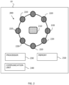
- Device 10 may be a wearable monitoring device configured to measure concentration of materials such as, glucose, albumin, insulin and the like, in a user's blood.
- Device 10 may include a measuring unit 200, a processor 230, a communication unit 240 and a memory 250.
- Measuring unit 200 may include at least one sensor 210 and at least one light emitting source 220.
- measuring unit 200 may be adjacent to and in contact with the skin of a subject so as to reduce noise from the environment. It should be noted that with light emitted from the at least one light emitting source 220, device 10 may perform optical measurements that are noninvasive in contrast to commercially available invasive and minimal invasive solutions.
- the EM radiation emitted from the at least one light emitting source 220 may be reflected from a subcutaneous tissue of the subject, and then detected by the at least one sensor 210 that may be, according to some embodiments, in the Infra-Red or near Infra-Red (IR) spectrum.
- IR Infra-Red
- SWIR Short Wave IR
- the SWIR waveband runs from the lower edge of the near IR region at 900nm up to 2500 nm, and may be utilized for inspection of blood vessels in the body of the subject. It should be noted that if required, the range of the SWIR waveband may be increased.
- device 10 may include measuring unit 200 in various configurations, and in some embodiments a single sensor 210 is surrounded by a plurality of light emitting sources 220 (as for example illustrated in Fig. 2 ). Other configuration may also employ a plurality of sensors 210 and light emitting sources.
- each light emitting source 220, or sub-sets (e.g. pairs, triplets etc.) of light emitting sources 220 may emit light in a different predetermined wavelength.
- each light emitting source 220 may emit light in a different time and/or in a different frequency, such that not all light emitting sources 220 emit light simultaneously. This may provide additional information on the reflected tissue when the time intervals between the emissions of light beams are known.
- the frequency of sampling by each light emitting source 220, or by each sub-set of light emitting sources 220 may be equal to or higher than Nyquist rate of the measured physiological signal.
- polarized optical means may be utilized in order to increase the accuracy in the optical measurements. Specifically, emitting light beams with a predetermined polarization and receiving these beams with a substantially different polarization, for instance with dedicated filters, may improve the signal to noise ratio in the measurements. Furthermore, such polarizing may also provide improved indication on the penetration of the light beam into the tissue as noises from the external skin layer may be reduced while only signals from the beam reflected of the blood vessels is measured.
- sensors may also be utilized.
- acoustic ultrasound sensors as well as terahertz sensors, RF sensors, microwave sensors and corresponding energy sources.
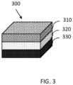
- a calibrating element 300 includes a first layer 310 simulating a specific human skin characteristics and a second layer 320 consisting a specific concentration of one or more materials in the blood, for example, glucose, albumin and insulin or a combination thereof.
- the specific concentration may include specific concentrations of more than one material, for example, albumin and insulin.
- Skin characteristic according to embodiments of the invention include at least one of: skin thickness, skin temperature skin color, skin hair density, skin optical properties, and skin hair color.
- the skin optical properties may include the ability of the skin to absorb, reflect and/or scattered EM radiation, for example, short wave infrared.
- the skin optical properties may include the scattering parameter (S-parameters) matrix.
- calibrating element 300 further includes a third layer 330 for simulating illumination reflection from a blood vessel in a skin tissue and for isolating the element from noise and reflections not related to the measured one or more materials in the second layer.
- Calibrating element 300 may include substantially the same types of layers as calibrating elements 105a-105d, 106a-106d and 107a-107b illustrated in Fig. 1 .
- calibrating element 300, 105a-105d, 106a-106d and 107a-107b may be configured to allow device 10 to be attached to the calibrating element in such a way that external light radiation does not interfere with the sent EM radiation and read EM reflections from the calibrating element.
- calibrating element 300, 105a-105d, 106a-106d and 107a-107b may have a cylindrical shape to emulate the form of a human wrist or arm. Other shapes may be used.
- First layer 310 may include any material that may simulate the EM absorption properties of the human skin.
- first layer 310 may include materials that simulate melanin chromophores, skin proteins (collagen, elastin), water, blood lipids, hemoglobin or other blood components, that may simulate the reaction of a human skin to EM radiation emitted from one or more emitting sources 220.
- Some of calibration elements 300 may have (when not falling under the scope of the claims) different first layers simulating different skin characteristics.
- sets 105, 106 and 107 may vary in the simulated thickness for example, elements 105a-105d may all have the same first layer simulating a skin thickness of 2 mm; elements 106a-106d may all have the same first layer simulating a skin thickness of 3 mm and elements 107a-107d may all have the same first layer simulated a skin thickness of 5 mm.
- system 100 of Fig. 1 may include sets having skin thicknesses of 2, 2.25, 2.5, 2.75, 3, 3.25 etc.75 and 5 mm.
- At least some of the sets of calibrating elements may simulate different skin color& tone in addition to different skin thickness.
- set 106 and set 107 may both simulate a skin thickness of 2.5 mm but with different amount of color pigment such as melanin chromophores, hemoglobin, other blood components, skin proteins (Elastin, collagen) etc..
- Second layer 320 may include a liquid or solid solution comprising a specific concentration of one or more materials to be measured in the blood.
- second layer 320 may include a specific concentration of albumin and/or glucose.
- each calibrating element in a set of calibrating elements may include a different second layer having a different concentration of the one or more materials.
- calibrating element 105a may include 3.5 g/dL of albumin
- element 105b may include 3.6 g/dL of albumin
- element 105c may include 3.7 g/dL of albumin
- element 105d may include 3.8 g/dL of albumin.
- Similar or different albumin concentrations may be included in elements 106a-106d and 107a-107d.
- elements 106a-106d and 107a-107d may include different concentrations of albumin and glucose. It should be appreciated that while the example illustrated in Fig. 1 each set of elements 105, 106, 107 includes 4 calibration elements, any number of calibrating elements may be used in each set. Furthermore, it should be appreciated that according to some embodiments, different sets may have different number of calibrating elements.
- Third layer 330 may include any material that will isolate and absorb the electromagnetic radiation emitted from one or more emitting source 220 the way a human organ/skin will do.
- third layer 330 may include wood aluminum, metal, ,SWIR (short-wavelength infrared) opaque polymers and water.
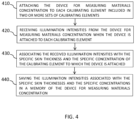
- Fig. 4 is a flowchart of a method of calibrating a device for measuring materials concentration in the blood according to some embodiments of the invention.
- the method of Fig. 4 may be performed using a system such as system 100.
- embodiments may include attaching the device for measuring materials concentration to each calibrating element included in two or more sets of calibrating elements.
- Device 10 may be attached, manually or automatically (e.g., by a robotic system) to at least some of the calibrating elements of system 100.
- device 10 may be attached first to each of calibrating elements 105a-105d of set 105 and then be attached to each of calibrating elements 106a-106d of set 106, and so on.
- each time device 10 is being attached to a calibrating element one or more light emitting sources 220 may emit EM radiation (e.g., light) into the calibrating element and one or more sensors 210 may read EM radiation reflected back from the calibrating element.
- Processor 230 may record in memory 250 the intensity (e.g., an optical value) at which the reflected EM radiation was sensed by one or more sensors 210.
- one or more light emitting sources 220 may emit light at several wavelengths, for example, at 1100 nm and 1290 nm and sensor 210 may sense two different intensities (e.g., different optical values) for each wavelength.
- processor 230 may be configured to send via communication unit 240 the recorded intensities to controller 110.
- embodiments may include receiving illumination intensities from the device for measuring materials concentration when the device is attached to each calibrating element.
- the illumination intensities may be affected by the optical characteristics of at least first layer 310 and second layer 320.
- the EM radiation reflected from second layer 320 may be affected by the ability of the material or materials in layer 320 (e.g., albumin and/or glucose) to absorb the EM radiation and the scattering, absorbing and reflecting properties of first layer 310.
- Processor 110 may receive from device 10, via communication unit 140 the sensed illumination intensities, sensed by sensor 210 for each calibrating element separately. Processor 110 may further receive information regarding form which calibrating element the illumination intensities was received and at which wavelength.
- each calibrating element may be marked with a machine readable tag such as an RFID tag, a barcode or the like.
- system 100 may further include a tag reader in communication with controller 110 that are configured to read an identification code included in the machine readable tag.
- processor 110 may associate the received illumination intensities with the specific skin characteristics and the specific concentration of the calibrating element to which the device is attached, in operation 430.
- the calibrating elements of table 1 includes at least two layers, a first layer simulating the skin thickness (2 mm for set 105 and 2.25 mm for set 106) and a second layer comprising albumin at concentrations of 3.5-3.7 g/dL.
- Table 1 Wavelength of 1100 nm Wavelength of 1290 nm element Albumin concentration [g/dL] Optical value [mW] element Albumin concentration [g/dL] Optical value [mW] Set 105 simulating skin thickness of 2 mm Set 105 simulating skin thickness of 2 mm 105a 3.5 10 105a 3.5 11 105b 3.6 13 105b 3.6 14 105c 3.7 17 105c 3.7 19
- Processor 110 may form lookup tables, such as for example, table 1 and save the illumination intensities associated with the specific skin characteristics and the specific concentration in a memory (e.g., memory 250) of the device (e.g., device 10) for measuring materials concentration, in operation 440.
- a memory e.g., memory 250
- the device e.g., device 10.
- some of the sets from the at least two sets of calibrating elements may include simulating a human skin with a first amount of color pigments and some of the sets from the at least two sets of calibrating elements includes simulating a human skin with a second amount of color pigments.
- the received illumination intensities may include illumination intensities received from calibrating elements simulating a human skin with the first and second amount of color pigments.
- the lookup tables may further include illumination intensities associated with specific skin thickness having specific color (e.g., amount of pigment in the skin).
- a reading from sensor 210 following illumination at a known wavelength may be accurately associated to a concentration of one or more materials (e.g., albumin and glucose) in the blood using the lookup tables stored in memory 250.
- materials e.g., albumin and glucose
Landscapes
- Health & Medical Sciences (AREA)
- Life Sciences & Earth Sciences (AREA)
- Physics & Mathematics (AREA)
- General Health & Medical Sciences (AREA)
- Pathology (AREA)
- Engineering & Computer Science (AREA)
- Molecular Biology (AREA)
- Public Health (AREA)
- Veterinary Medicine (AREA)
- Heart & Thoracic Surgery (AREA)
- Optics & Photonics (AREA)
- Biophysics (AREA)
- Surgery (AREA)
- Biomedical Technology (AREA)
- Medical Informatics (AREA)
- Animal Behavior & Ethology (AREA)
- General Physics & Mathematics (AREA)
- Chemical & Material Sciences (AREA)
- Biochemistry (AREA)
- Analytical Chemistry (AREA)
- Immunology (AREA)
- Spectroscopy & Molecular Physics (AREA)
- Mathematical Physics (AREA)
- Theoretical Computer Science (AREA)
- Emergency Medicine (AREA)
- Measurement Of The Respiration, Hearing Ability, Form, And Blood Characteristics Of Living Organisms (AREA)
Description
- Noninvasive blood test measurements are the future of blood measurements. They are simple, harmless, unpainful and do not involve laboratory time. Several commercial products for noninvasive measurements are available today. However, for these devices to work properly they must be accurately calibrated to suit specific patients.
- Noninvasive blood test measurements are performed by attaching a measurement device to the patient's skin. These devices are usually operated by sending electromagnetic signals (e.g., visual light, IR radiation, RF radiation, etc.) via the patient skin targeting a blood vessel and reading reflection received from the blood vessel. Different humans' skin has different characteristics, such as, different thicknesses of different skin layers, different amount of hair, different amount of pigment etc., and therefore may absorb differently the electromagnetic signals sent from the noninvasive measurements device. Accordingly, there is a need for a noninvasive blood measurement deceive that may be calibrated specifically to each user so to measure accurately, concentrations of various materials in the blood for patients with different skin characteristics and different anatomy.
-
US2010042348 provides a method of calibrating an optical analysis system that makes use of multivariate optical signal analysis allowing to realize cost-efficient and robust implementation of a spectral analysis of an optical signal. The calibration method makes use of determining a parameter of a reference sample by means of the optical analysis system and comparing the actually determined parameter with a reference parameter that represents a precise and real property of the reference sample. Based on this comparison a calibration value can be determined that is applicable to perform a calibration of the optical analysis system with respect to at least one compound or analyte of the reference sample. Parameters and reference parameters of a reference sample may refer to a concentration of an analyte dissolved in the sample, or to spectroscopic background signals that have to be taken into account when performing a spectral analysis based on optical signals obtained from the reference sample. Various different reference samples providing a reference with respect to different acquisition conditions and different analyte or compound concentrations can be universally used. Analyte-specific reference data is preferably stored in a calibration unit of the optical analysis system and allows a high degree of automation of the calibration process. - Some aspects of the invention are directed to a system for calibrating a device for measuring materials concentration in the blood. The system includes at least two sets of calibrating elements, each set comprising a plurality of calibrating elements. Each of the calibrating elements includes, a first layer simulating a specific human skin characteristics; a second layer comprising a specific concentration of one or more materials in the blood; and a third layer for simulating illumination reflection from a blood vessel in a skin tissue. The specific human skin characteristics comprise at least one of: skin thickness, skin color, skin hair density, skin tone, skin temperature, skin optical properties and skin hair color. All calibrating elements in a set the first layer may be the same first layer simulating the same specific human skin characteristics such that each set of calibrating elements simulate different specific human skin characteristics. Each calibrating element in a set of calibrating elements includes a different second layer comprising a different concentration of the one or more material. The third layer isolates the calibrating element from noise and reflections not related to the measured one or more materials in the second layer. The system further includes a controller that is configured to: receive illumination intensities from the device for measuring materials concentration when the device is attached to each calibrating element of the system; associate the received illumination intensities with the specific human skin characteristics and the specific concentration of the calibrating element to which the device is attached; and save the illumination intensities associated with the specific human skin characteristics and the specific concentration in lookup tables in a memory of the device for measuring materials concentration.
- In some embodiments, the received illumination intensities may include illumination intensities at various wavelengths and the saved lookup tables include lookup tables for illumination intensities of a specific wavelength associated with the specific human skin characteristics, the one or more materials and the specific concentration. In some embodiments, the system may further include a third layer for simulating illumination reflection from a blood vessel in a skin tissue.
- An additional aspect of the present invention is related to a method of calibrating a device for measuring materials concentration in the blood. The method includes: attaching the device for measuring materials concentration to each calibrating element included in one of two or more sets of calibrating elements. Each of the calibrating elements includes: a first layer simulating specific human skin characteristics; a second layer comprising a specific concentration of one or more materials in the blood; and a third layer for simulating illumination reflection from a blood vessel in a skin tissue. The specific human skin characteristics comprise at least one of: skin thickness, skin color, skin hair density, skin tone, skin temperature, skin optical properties and skin hair color. In all calibrating elements in a set, the first layer is the same first layer simulating the same specific human skin characteristic and each set of calibrating elements simulates different specific human skin characteristics, each calibrating element in a set of calibrating elements includes a different second layer comprising a different concentration of the one or more materials, and the third layer isolates the calibrating element from noise and reflections not related to the measured one or more materials in the second layer. The method further includes: receiving, by a controller of a calibrating system, illumination intensities from the device for measuring materials concentration when the device is attached to each calibrating element; associating, by the controller, the received illumination intensities with the specific human skin characteristics and the specific concentration of the one or more materials in the second layer of the calibrating element to which the device is attached; and recording, by the controller, the illumination intensities associated with the specific human skin characteristics and the specific concentrations in a memory of the device for measuring materials concentration.
- In some embodiments, receiving illumination intensities may include receiving illumination intensities at various wavelengths and recording the illumination intensities may include creating lookup tables for illumination intensities of a specific wavelength associated with the specific human skin characteristic and the specific concentration.
- The subject matter regarded as the invention is defined by the claims. The invention, however, both as to organization and method of operation, together with objects, features, and advantages thereof, may best be understood by reference to the following detailed description when read with the accompanying drawings in which:
-
Fig. 1 is diagrammatic representation of a system for calibrating a device for measuring materials concentration in the blood according to some embodiments of the invention; -
Fig. 2 is an illustration of a measurement device according to some embodiments of the invention; -
Fig. 3 is an illustration of a calibrating element according to some embodiments of the invention; and -
Fig. 4 is a flowchart of a method of calibrating a device for measuring materials concentration in the blood according to some embodiments of the invention. - It will be appreciated that for simplicity and clarity of illustration, elements shown in the figures have not necessarily been drawn to scale. For example, the dimensions of some of the elements may be exaggerated relative to other elements for clarity. Further, where considered appropriate, reference numerals may be repeated among the figures to indicate corresponding or analogous elements.
- In the following detailed description, numerous specific details are set forth in order to provide a thorough understanding of the invention. However, it will be understood by those skilled in the art that the invention may be practiced without these specific details. In other instances, well-known methods, procedures, and components modules, units and/or circuits have not been described in detail so as not to obscure the invention. Some features or elements described with respect to one embodiment may be combined with features or elements described with respect to other embodiments. For the sake of clarity, discussion of same or similar features or elements may not be repeated.
- Although embodiments of the invention are not limited in this regard, discussions utilizing terms such as, for example, "processing," "computing," "calculating," "determining," "establishing", "analyzing", "checking", or the like, may refer to operation(s) and/or process(es) of a computer, a computing platform, a computing system, or other electronic computing device, that manipulates and/or transforms data represented as physical (e.g., electronic) quantities within the computer's registers and/or memories into other data similarly represented as physical quantities within the computer's registers and/or memories or other information non-transitory storage medium that may store instructions to perform operations and/or processes. Although embodiments of the invention are not limited in this regard, the terms "plurality" and "a plurality" as used herein may include, for example, "multiple" or "two or more". The terms "plurality" or "a plurality" may be used throughout the specification to describe two or more components, devices, elements, units, parameters, or the like. The term set when used herein may include one or more items. Unless explicitly stated, the method embodiments described herein are not constrained to a particular order or sequence. Additionally, some of the described method embodiments or elements thereof can occur or be performed simultaneously, at the same point in time, or concurrently.
- Reference is now made to
Fig. 1 which is a diagrammatic representation of a system for calibrating a device for measuring materials concentration in the blood according to some embodiments of the invention.System 100 includes at least twosets elements 105a-105d and 106a-106d. In some embodiments,system 100 may include additional sets, for example, set 107, of calibratingelements 107a-107d. A detailed description of a calibrating element is given with respect toFig. 3 .System 100 further includes acontroller 110, and may include a storage unit 120 auser interface 130 and acommunication unit 140.Communication unit 140 may be configured to send and receive information from adevice 10 for measuring materials concentration in the blood. - In some embodiments,
controller 110 may include aprocessor 112 that may be, for example, a central processing unit (CPU), a chip or any suitable computing or computational device, anoperating system 114 and amemory 116.System 100 may include a desktop computer, laptop commuter, a tablet, a mainframe computer or the like.Processor 112 may be configured to carry out methods according to embodiments of the present invention by for example executing instructions stored in a memory such asmemory 116. -
Operating system 114 may be or may include any code segment designed and/or configured to perform tasks involving coordination, scheduling, arbitration, supervising, controlling or otherwise managing operation ofcontroller 110, for example, scheduling execution of programs.Operating system 114 may be a commercial operating system.Memory 116 may be or may include, for example, a Random Access Memory (RAM), a read only memory (ROM), a Dynamic RAM (DRAM), a Synchronous DRAM (SD-RAM), a double data rate (DDR) memory chip, a Flash memory, a volatile memory, a non-volatile memory, a cache memory, a buffer, a short term memory unit, a long term memory unit, or other suitable memory units or storage units.Memory 116 may be or may include a plurality of, possibly different memory units. -
Memory 116 may store any executable code, e.g., an application, a program, a process, task or script. The executable code may include codes for calibrating a device for measuring materials concentration in the blood or any other codes or instruction for executing methods according to embodiments of the present invention. The executable code may be executed byprocessor 112 possibly under control ofoperating system 114. -
Storage 120 may be or may include, for example, a hard disk drive, a floppy disk drive, a Compact Disk (CD) drive, a CD-Recordable (CD-R) drive, a universal serial bus (USB) device or other suitable removable and/or fixed storage unit. Content may be stored instorage 120 and may be loaded fromstorage 120 intomemory 116 where it may be processed byprocessor 112. For example,storage 120 may include reference data related to measuring materials concentration in the blood, such as amplitude of reflected IR light in different wave lengths , representing: glucose blood levels, LDL (low density lipoproteins) levels in the blood , HDL (high density lipoprotein )levels in the blood ,cholesterol levels in the blood , TG( Tri Glycerides) levels in the blood , Albumin levels in the blood Hemoglobin levels in the blood cardiac pulse frequency , cardiac pulse signal intensity, skin temp rate, body movement or lack of movement, body acceleration in different directions horizontal positioning , skin thickness, skin pigmentation, -
User interface 130 may be or may include a screen, a pointing device and an audio device or any other device that may allow a user to send instructions and/or information tocontroller 110 and receive information fromcontroller 110. For example,user interface 130 may include, a mouse, a touch screen or a pad, a keyboard, a microphone, speakers and the like. - In some embodiments,
system 100 may further include acommunication unit 140 for communication with at least onedevice 10 for measuring materials concentration in the blood.Communication unit 140 may include any applicable input/output (I/O) devices toconnected controller 110 anddevice 10, for example, a wired or wireless network interface card (NIC), a modem, a universal serial bus (USB) device or external hard drive and the like. - Embodiments of the invention may include an article such as a computer or processor non-transitory readable medium, or a computer or processor non-transitory storage medium, such as for example a memory, a disk drive, or a USB flash memory, encoding, including or storing instructions, e.g., computer-executable instructions, which, when executed by a processor or controller, carry out methods disclosed herein.
- The storage medium may include, but is not limited to, any type of disk including floppy disks, optical disks, compact disk read-only memories (CD-ROMs), rewritable compact disk (CD-RWs), and magneto-optical disks, semiconductor devices such as read-only memories (ROMs), random access memories (RAMs), such as a dynamic RAM (DRAM), erasable programmable read-only memories (EPROMs), flash memories, electrically erasable programmable read-only memories (EEPROMs), magnetic or optical cards, or any type of media suitable for storing electronic instructions, including programmable storage unit.
- A system according to embodiments of the invention may include components such as, but not limited to, a plurality of central processing units (CPU) or any other suitable multi-purpose or specific processors or controllers, a plurality of input units, a plurality of output units, a plurality of memory units, and a plurality of storage units. A system may additionally include other suitable hardware components and/or software components. In some embodiments, a system may include or may be, for example, a personal computer, a desktop computer, a mobile computer, a laptop computer, a notebook computer, a terminal, a workstation, a server computer, a tablet computer, a network device, or any other suitable computing device. Unless explicitly stated, the method embodiments described herein are not constrained to a particular order or sequence. Additionally, some of the described method embodiments or elements thereof can occur or be performed at the same point in time.
- Reference is now made to
Fig. 2 which is an illustration of a device for measuring materials concentration in the blood according to some embodiments of the invention.Device 10 may be a wearable monitoring device configured to measure concentration of materials such as, glucose, albumin, insulin and the like, in a user's blood.Device 10 may include a measuringunit 200, aprocessor 230, acommunication unit 240 and amemory 250. Measuringunit 200 may include at least onesensor 210 and at least onelight emitting source 220. In some embodiments, measuringunit 200 may be adjacent to and in contact with the skin of a subject so as to reduce noise from the environment. It should be noted that with light emitted from the at least onelight emitting source 220,device 10 may perform optical measurements that are noninvasive in contrast to commercially available invasive and minimal invasive solutions. - According to some embodiments, the EM radiation emitted from the at least one
light emitting source 220, may be reflected from a subcutaneous tissue of the subject, and then detected by the at least onesensor 210 that may be, according to some embodiments, in the Infra-Red or near Infra-Red (IR) spectrum. For example, Short Wave IR (SWIR) imaging is utilized for measuring physiological signals from the blood of a subject. The SWIR waveband runs from the lower edge of the near IR region at 900nm up to 2500 nm, and may be utilized for inspection of blood vessels in the body of the subject. It should be noted that if required, the range of the SWIR waveband may be increased. - It should be noted that
device 10 may include measuringunit 200 in various configurations, and in some embodiments asingle sensor 210 is surrounded by a plurality of light emitting sources 220 (as for example illustrated inFig. 2 ). Other configuration may also employ a plurality ofsensors 210 and light emitting sources. - In some embodiment, each light emitting
source 220, or sub-sets (e.g. pairs, triplets etc.) oflight emitting sources 220 may emit light in a different predetermined wavelength. - In some embodiment, each light emitting
source 220, or sub-set of light emittingsources 220, may emit light in a different time and/or in a different frequency, such that not alllight emitting sources 220 emit light simultaneously. This may provide additional information on the reflected tissue when the time intervals between the emissions of light beams are known. - According to some embodiments, the frequency of sampling by each light emitting
source 220, or by each sub-set of light emittingsources 220, may be equal to or higher than Nyquist rate of the measured physiological signal. - In some non-limiting embodiments, polarized optical means may be utilized in order to increase the accuracy in the optical measurements. Specifically, emitting light beams with a predetermined polarization and receiving these beams with a substantially different polarization, for instance with dedicated filters, may improve the signal to noise ratio in the measurements. Furthermore, such polarizing may also provide improved indication on the penetration of the light beam into the tissue as noises from the external skin layer may be reduced while only signals from the beam reflected of the blood vessels is measured.
- In some non-limiting embodiments, other sensors may also be utilized. For example acoustic ultrasound sensors, as well as terahertz sensors, RF sensors, microwave sensors and corresponding energy sources.
- Reference is now made to
Fig. 3 which is an illustration of a calibrating element according to some embodiments of the invention. A calibratingelement 300 includes afirst layer 310 simulating a specific human skin characteristics and asecond layer 320 consisting a specific concentration of one or more materials in the blood, for example, glucose, albumin and insulin or a combination thereof. In some embodiments, the specific concentration may include specific concentrations of more than one material, for example, albumin and insulin. Skin characteristic according to embodiments of the invention include at least one of: skin thickness, skin temperature skin color, skin hair density, skin optical properties, and skin hair color. In some embodiments, the skin optical properties may include the ability of the skin to absorb, reflect and/or scattered EM radiation, for example, short wave infrared. The skin optical properties may include the scattering parameter (S-parameters) matrix. - According to the invention, calibrating
element 300 further includes athird layer 330 for simulating illumination reflection from a blood vessel in a skin tissue and for isolating the element from noise and reflections not related to the measured one or more materials in the second layer. Calibratingelement 300 may include substantially the same types of layers as calibratingelements 105a-105d, 106a-106d and 107a-107b illustrated inFig. 1 . In some embodiments, calibratingelement device 10 to be attached to the calibrating element in such a way that external light radiation does not interfere with the sent EM radiation and read EM reflections from the calibrating element. For example, calibratingelement -
First layer 310 may include any material that may simulate the EM absorption properties of the human skin. For example,first layer 310 may include materials that simulate melanin chromophores, skin proteins (collagen, elastin), water, blood lipids, hemoglobin or other blood components, that may simulate the reaction of a human skin to EM radiation emitted from one or more emittingsources 220. Some ofcalibration elements 300 may have (when not falling under the scope of the claims) different first layers simulating different skin characteristics. In some embodiments, sets 105, 106 and 107 may vary in the simulated thickness for example,elements 105a-105d may all have the same first layer simulating a skin thickness of 2 mm;elements 106a-106d may all have the same first layer simulating a skin thickness of 3 mm andelements 107a-107d may all have the same first layer simulated a skin thickness of 5 mm. In some embodiments,system 100 ofFig. 1 may include sets having skin thicknesses of 2, 2.25, 2.5, 2.75, 3, 3.25.....4.75 and 5 mm. - In some embodiments, at least some of the sets of calibrating elements may simulate different skin color& tone in addition to different skin thickness. For example, set 106 and set 107 may both simulate a skin thickness of 2.5 mm but with different amount of color pigment such as melanin chromophores, hemoglobin, other blood components, skin proteins (Elastin, collagen) etc..
-
Second layer 320 may include a liquid or solid solution comprising a specific concentration of one or more materials to be measured in the blood. For example,second layer 320 may include a specific concentration of albumin and/or glucose. In some embodiments, each calibrating element in a set of calibrating elements may include a different second layer having a different concentration of the one or more materials. For example, calibratingelement 105a may include 3.5 g/dL of albumin,element 105b may include 3.6 g/dL of albumin,element 105c may include 3.7 g/dL of albumin andelement 105d may include 3.8 g/dL of albumin. Similar or different albumin concentrations may be included inelements 106a-106d and 107a-107d. In yet another example,elements 106a-106d and 107a-107d may include different concentrations of albumin and glucose. It should be appreciated that while the example illustrated inFig. 1 each set ofelements -
Third layer 330 may include any material that will isolate and absorb the electromagnetic radiation emitted from one or moreemitting source 220 the way a human organ/skin will do. For example,third layer 330 may include wood aluminum, metal, ,SWIR (short-wavelength infrared) opaque polymers and water. - Reference is now made to
Fig. 4 which is a flowchart of a method of calibrating a device for measuring materials concentration in the blood according to some embodiments of the invention. The method ofFig. 4 may be performed using a system such assystem 100. Inoperation 410, embodiments may include attaching the device for measuring materials concentration to each calibrating element included in two or more sets of calibrating elements.Device 10 may be attached, manually or automatically (e.g., by a robotic system) to at least some of the calibrating elements ofsystem 100. For example,device 10 may be attached first to each of calibratingelements 105a-105d ofset 105 and then be attached to each of calibratingelements 106a-106d ofset 106, and so on. - In some embodiments, each
time device 10 is being attached to a calibrating element, one or morelight emitting sources 220 may emit EM radiation (e.g., light) into the calibrating element and one ormore sensors 210 may read EM radiation reflected back from the calibrating element.Processor 230 may record inmemory 250 the intensity (e.g., an optical value) at which the reflected EM radiation was sensed by one ormore sensors 210. In some embodiments, one or morelight emitting sources 220 may emit light at several wavelengths, for example, at 1100 nm and 1290 nm andsensor 210 may sense two different intensities (e.g., different optical values) for each wavelength. In some embodiments,processor 230 may be configured to send viacommunication unit 240 the recorded intensities tocontroller 110. - In
operation 420, embodiments may include receiving illumination intensities from the device for measuring materials concentration when the device is attached to each calibrating element. In some embodiments, the illumination intensities may be affected by the optical characteristics of at leastfirst layer 310 andsecond layer 320. The EM radiation reflected fromsecond layer 320 may be affected by the ability of the material or materials in layer 320 (e.g., albumin and/or glucose) to absorb the EM radiation and the scattering, absorbing and reflecting properties offirst layer 310.Processor 110 may receive fromdevice 10, viacommunication unit 140 the sensed illumination intensities, sensed bysensor 210 for each calibrating element separately.Processor 110 may further receive information regarding form which calibrating element the illumination intensities was received and at which wavelength. In some embodiments, each calibrating element may be marked with a machine readable tag such as an RFID tag, a barcode or the like. In some embodiments,system 100 may further include a tag reader in communication withcontroller 110 that are configured to read an identification code included in the machine readable tag. - Accordingly,
processor 110 may associate the received illumination intensities with the specific skin characteristics and the specific concentration of the calibrating element to which the device is attached, inoperation 430. - An example for intensities (optical values) recorded for various calibrating elements at two wavelengths is given in table 1. The calibrating elements of table 1 includes at least two layers, a first layer simulating the skin thickness (2 mm for
set 105 and 2.25 mm for set 106) and a second layer comprising albumin at concentrations of 3.5-3.7 g/dL.Table 1: Wavelength of 1100 nm Wavelength of 1290 nm element Albumin concentration [g/dL] Optical value [mW] element Albumin concentration [g/dL] Optical value [mW] Set 105 simulating skin thickness of 2mm Set 105 simulating skin thickness of 2 mm 105a 3.5 10 105a 3.5 11 105b 3.6 13 105b 3.6 14 105c 3.7 17 105c 3.7 19 Set 106 simulating skin thickness of 2.25mm Set 106 simulating skin thickness of 2.25 mm 106a 3.5 9 106a 3.5 10 106b 3.6 12 106b 3.6 13 106c 3.7 16 106c 3.7 18 -
Processor 110 may form lookup tables, such as for example, table 1 and save the illumination intensities associated with the specific skin characteristics and the specific concentration in a memory (e.g., memory 250) of the device (e.g., device 10) for measuring materials concentration, inoperation 440. - In some embodiments, some of the sets from the at least two sets of calibrating elements may include simulating a human skin with a first amount of color pigments and some of the sets from the at least two sets of calibrating elements includes simulating a human skin with a second amount of color pigments. In some embodiments, the received illumination intensities may include illumination intensities received from calibrating elements simulating a human skin with the first and second amount of color pigments. Accordingly, the lookup tables may further include illumination intensities associated with specific skin thickness having specific color (e.g., amount of pigment in the skin).
- Accordingly, when
device 10 is attached to a human's skin (e.g., human hand) with known skin thickness a reading fromsensor 210 following illumination at a known wavelength may be accurately associated to a concentration of one or more materials (e.g., albumin and glucose) in the blood using the lookup tables stored inmemory 250. - While certain features of the invention have been illustrated and described herein, many modifications, substitutions, changes, and equivalents will now occur to those of ordinary skill in the art.
Claims (4)
- A system (100) for calibrating a device for measuring materials concentration in the blood, comprising:at least two sets (105),(106),(107) of calibrating elements (105a-105d) (106a-106d), (107a-107d) (300), each set comprising a plurality of calibrating elements,wherein each of the calibrating elements comprises:a first layer (310) simulating specific human skin characteristics;a second layer (320) comprising a specific concentration of one or more materials in the blood;wherein the specific human skin characteristics comprise at least one of: skin thickness, skin color, skin hair density, skin tone, skin temperature, skin optical properties and skin hair color,wherein in all calibrating elements in a set the first layer is the same first layer simulating the same specific human skin characteristics and each set of calibrating elements simulate different specific human skin characteristics,wherein each calibrating element in a set of calibrating elements comprises a different second layer comprising a different concentration of the one or more materials; anda controller (110) configured to:characterized in thatreceive illumination intensities from the device for measuring materials concentration when the device is attached to each calibrating element of the system;associate the received illumination intensities with the specific human skin characteristics and the specific concentration of the calibrating element to which the device is attached; andsave the illumination intensities associated with the specific human skin characteristics and the specific concentration in lookup tables in memory of the device for measuring materials concentration,
each of the calibrating elements further comprises a third layer (330) for simulating illumination reflection from a blood vessel in a skin tissue, wherein the third layer isolates the calibrating element from noise and reflections not related to the measured one or more materials in the second layer. - The system of claim 1, wherein the received illumination intensities include illumination intensities at various wavelengths and wherein the saved lookup tables include lookup tables for illumination intensities of a specific wavelength associated with the specific human skin characteristics, the one or more materials and the specific concentration.
- A method of calibrating a device for measuring materials concentration in the blood, the method comprising:attaching the device for measuring materials concentration to each calibrating element included in one of two or more sets of calibrating elements (410),wherein each of the calibrating elements comprises:a first layer simulating specific human skin characteristics;a second layer comprising a specific concentration of one or more materials in the blood;wherein the specific human skin characteristics comprise at least one of: skin thickness, skin color, skin hair density, skin tone, skin temperature, skin optical properties and skin hair color,wherein in all calibrating elements in a set the first layer is the same first layer simulating the same specific human skin characteristics and each set of calibrating elements simulate different specific human skin characteristics,wherein each calibrating element in a set of calibrating elements comprises a different second layer comprising a different concentration of the one or more materials;receiving, by a controller of a calibrating system, illumination intensities from the device for measuring materials concentration when the device is attached to each calibrating element (420);associating, by the controller, the received illumination intensities with the specific human skin characteristics and the specific concentration of the one or more materials in the second layer of the calibrating element to which the device is attached (430); andrecording, by the controller, the illumination intensities associated with the specific human skin characteristics and the specific concentration in a memory of the device for measuring materials concentration (440),characterized in that
each of the calibrating elements further comprises a third layer (330) for simulating illumination reflection from a blood vessel in a skin tissue, wherein the third layer isolates the calibrating element from noise and reflections not related to the measured one or more materials in the second layer. - The method of claim 3, wherein receiving illumination intensities includes receiving illumination intensities at various wavelengths and wherein recording the illumination intensities includes creating lookup tables for illumination intensities of a specific wavelength associated with the specific human skin characteristics and the specific concentration.
Applications Claiming Priority (2)
| Application Number | Priority Date | Filing Date | Title |
|---|---|---|---|
| US201662404813P | 2016-10-06 | 2016-10-06 | |
| PCT/IL2017/051115 WO2018065981A1 (en) | 2016-10-06 | 2017-10-02 | Device, system and method for calibrating a non-invasive health monitoring device |
Publications (4)
| Publication Number | Publication Date |
|---|---|
| EP3522783A1 EP3522783A1 (en) | 2019-08-14 |
| EP3522783A4 EP3522783A4 (en) | 2020-06-17 |
| EP3522783C0 EP3522783C0 (en) | 2024-09-11 |
| EP3522783B1 true EP3522783B1 (en) | 2024-09-11 |
Family
ID=61831663
Family Applications (1)
| Application Number | Title | Priority Date | Filing Date |
|---|---|---|---|
| EP17857972.8A Active EP3522783B1 (en) | 2016-10-06 | 2017-10-02 | Device, system and method for calibrating a non-invasive health monitoring device |
Country Status (6)
| Country | Link |
|---|---|
| US (1) | US11633135B2 (en) |
| EP (1) | EP3522783B1 (en) |
| JP (1) | JP7071970B2 (en) |
| CN (1) | CN110139604B (en) |
| IL (1) | IL265813B2 (en) |
| WO (1) | WO2018065981A1 (en) |
Families Citing this family (1)
| Publication number | Priority date | Publication date | Assignee | Title |
|---|---|---|---|---|
| EP3923806B1 (en) * | 2019-02-15 | 2024-01-10 | Siemens Healthcare Diagnostics Inc. | Calibrators and controls for the determination of the percentage of glycated hemoglobin in a patient's liquid test sample |
Family Cites Families (13)
| Publication number | Priority date | Publication date | Assignee | Title |
|---|---|---|---|---|
| US6456870B1 (en) | 1999-07-22 | 2002-09-24 | Sensys Medical, Inc. | Non-invasive method of determining skin thickness and characterizing layers of skin tissue in vivo |
| US6196046B1 (en) | 1999-08-25 | 2001-03-06 | Optiscan Biomedical Corporation | Devices and methods for calibration of a thermal gradient spectrometer |
| US20020133080A1 (en) * | 2001-02-06 | 2002-09-19 | William Apruzzese | Layered calibration standard for tissue sampling |
| CN105380608A (en) * | 2003-02-26 | 2016-03-09 | 马尔西奥·马克·奥雷利奥·马丁斯·阿布雷乌 | Apparatus and methods for measuring biological parameters |
| EP1828731A1 (en) | 2004-12-15 | 2007-09-05 | Koninklijke Philips Electronics N.V. | Calibration of optical analysis making use of multivariate optical elements |
| US7729734B2 (en) * | 2006-03-07 | 2010-06-01 | Andreas Mandelis | Non-invasive biothermophotonic sensor for blood glucose monitoring |
| JP4697000B2 (en) | 2006-03-27 | 2011-06-08 | パナソニック電工株式会社 | Body component measuring device |
| RU2398232C2 (en) * | 2008-11-21 | 2010-08-27 | Государственное учреждение Московский областной научно-исследовательский клинический институт им. М.Ф. Владимирского (МОНИКИ им. М.Ф. Владимирского) | Device for calibration of medical diagnostic spectrophotometric devices |
| US20120095305A1 (en) * | 2009-06-15 | 2012-04-19 | O2 Medtech, Inc. | Spectrophotometric Monitoring Of Multiple Layer Tissue Structures |
| WO2013077077A1 (en) | 2011-11-22 | 2013-05-30 | 株式会社アドバンテスト | Phantom for measuring biological light, phantom laminate, and manufacturing method for phantom |
| CN103932718B (en) * | 2013-01-17 | 2015-12-02 | 北京怡成生物电子技术股份有限公司 | The portable monitoring system of thing is analyzed in dynamic METHOD FOR CONTINUOUS DETERMINATION body fluid |
| WO2016054079A1 (en) | 2014-09-29 | 2016-04-07 | Zyomed Corp. | Systems and methods for blood glucose and other analyte detection and measurement using collision computing |
| JP2016150130A (en) | 2015-02-18 | 2016-08-22 | セイコーエプソン株式会社 | Information acquisition device and information acquisition method |
-
2017
- 2017-10-02 WO PCT/IL2017/051115 patent/WO2018065981A1/en not_active Ceased
- 2017-10-02 US US16/339,403 patent/US11633135B2/en active Active
- 2017-10-02 EP EP17857972.8A patent/EP3522783B1/en active Active
- 2017-10-02 CN CN201780075317.3A patent/CN110139604B/en active Active
- 2017-10-02 JP JP2019518309A patent/JP7071970B2/en active Active
- 2017-10-02 IL IL265813A patent/IL265813B2/en unknown
Also Published As
| Publication number | Publication date |
|---|---|
| WO2018065981A1 (en) | 2018-04-12 |
| JP7071970B2 (en) | 2022-05-19 |
| EP3522783A1 (en) | 2019-08-14 |
| EP3522783A4 (en) | 2020-06-17 |
| IL265813B1 (en) | 2023-12-01 |
| CN110139604B (en) | 2023-01-13 |
| IL265813A (en) | 2019-06-30 |
| EP3522783C0 (en) | 2024-09-11 |
| JP2019534075A (en) | 2019-11-28 |
| IL265813B2 (en) | 2024-04-01 |
| US20200037933A1 (en) | 2020-02-06 |
| CN110139604A (en) | 2019-08-16 |
| US11633135B2 (en) | 2023-04-25 |
Similar Documents
| Publication | Publication Date | Title |
|---|---|---|
| TW570768B (en) | Classification and characterization of tissue through features related to adipose tissue | |
| Currà et al. | Near-infrared spectroscopy as a tool for in vivo analysis of human muscles | |
| EP3397139B1 (en) | Device, system and method for non-invasive monitoring of physiological measurements | |
| US6788965B2 (en) | Intelligent system for detecting errors and determining failure modes in noninvasive measurement of blood and tissue analytes | |
| CN101557752B (en) | Glucose concentration measurement method in pulsatile blood | |
| US12089928B2 (en) | Device, system and method for non-invasive monitoring of physiological measurements | |
| CN112465077B (en) | Nondestructive testing method, device, computer equipment and storage medium for fruit sugar content | |
| KR101536287B1 (en) | Total medical test system using smart-phone | |
| Vaudelle et al. | Influence of the size and skin thickness of apple varieties on the retrieval of internal optical properties using Vis/NIR spectroscopy: A Monte Carlo-based study | |
| US11633135B2 (en) | Device, system and method for calibrating a non-invasive health monitoring device | |
| JP2019513071A (en) | Direct infrared analysis of posttranslational modifications of proteins | |
| Barati et al. | Principal component analysis and near-infrared spectroscopy as noninvasive blood glucose assay methods | |
| Darmawan et al. | Non-invasive iot home medical check-up programming to monitor blood sugar, cholesterol, uric acid, and body temperature | |
| Andarabi et al. | Analysis of glucose concentrations in blood solutions using FTIR and Raman spectroscopy methods | |
| Bai et al. | Assessing and advancing technology for the noninvasive measurement of clinical glucose | |
| Westman et al. | Skin pigmentation affects ViOptix T. Ox performance in variably pigmented preclinical model of flap ischemia and congestion | |
| WO2009136338A1 (en) | An adaptable probe having illumination and detection elements | |
| Baig | Near-Infrared Spectroscopy (NIRS) for Non-Invasive Diagnosis | |
| Wang et al. | Optical properties and Monte Carlo simulation of light propagation in bruised potato tissues | |
| JP7705640B2 (en) | Analytical device and analytical method | |
| Manoj et al. | IoT based on Fruit Quality Detection System with Biosensor Technology | |
| EP3426153B1 (en) | Direct infrared analysis of post-translational modification of proteins | |
| WO2025111507A1 (en) | Methods and systems for estimating blood analyte conditions | |
| Parab et al. | Spectroscopy on Glucose Prediction | |
| Ye | Mechanical and morphological alternations in skin tissue due to thermal injury |
Legal Events
| Date | Code | Title | Description |
|---|---|---|---|
| STAA | Information on the status of an ep patent application or granted ep patent |
Free format text: STATUS: THE INTERNATIONAL PUBLICATION HAS BEEN MADE |
|
| PUAI | Public reference made under article 153(3) epc to a published international application that has entered the european phase |
Free format text: ORIGINAL CODE: 0009012 |
|
| STAA | Information on the status of an ep patent application or granted ep patent |
Free format text: STATUS: REQUEST FOR EXAMINATION WAS MADE |
|
| 17P | Request for examination filed |
Effective date: 20190415 |
|
| AK | Designated contracting states |
Kind code of ref document: A1 Designated state(s): AL AT BE BG CH CY CZ DE DK EE ES FI FR GB GR HR HU IE IS IT LI LT LU LV MC MK MT NL NO PL PT RO RS SE SI SK SM TR |
|
| AX | Request for extension of the european patent |
Extension state: BA ME |
|
| DAV | Request for validation of the european patent (deleted) | ||
| DAX | Request for extension of the european patent (deleted) | ||
| A4 | Supplementary search report drawn up and despatched |
Effective date: 20200519 |
|
| RIC1 | Information provided on ipc code assigned before grant |
Ipc: A61B 5/145 20060101AFI20200513BHEP Ipc: G01N 21/27 20060101ALI20200513BHEP Ipc: G01J 3/28 20060101ALI20200513BHEP |
|
| STAA | Information on the status of an ep patent application or granted ep patent |
Free format text: STATUS: EXAMINATION IS IN PROGRESS |
|
| 17Q | First examination report despatched |
Effective date: 20230627 |
|
| GRAP | Despatch of communication of intention to grant a patent |
Free format text: ORIGINAL CODE: EPIDOSNIGR1 |
|
| STAA | Information on the status of an ep patent application or granted ep patent |
Free format text: STATUS: GRANT OF PATENT IS INTENDED |
|
| INTG | Intention to grant announced |
Effective date: 20240416 |
|
| GRAS | Grant fee paid |
Free format text: ORIGINAL CODE: EPIDOSNIGR3 |
|
| GRAA | (expected) grant |
Free format text: ORIGINAL CODE: 0009210 |
|
| STAA | Information on the status of an ep patent application or granted ep patent |
Free format text: STATUS: THE PATENT HAS BEEN GRANTED |
|
| AK | Designated contracting states |
Kind code of ref document: B1 Designated state(s): AL AT BE BG CH CY CZ DE DK EE ES FI FR GB GR HR HU IE IS IT LI LT LU LV MC MK MT NL NO PL PT RO RS SE SI SK SM TR |
|
| REG | Reference to a national code |
Ref country code: GB Ref legal event code: FG4D |
|
| REG | Reference to a national code |
Ref country code: CH Ref legal event code: EP |
|
| REG | Reference to a national code |
Ref country code: DE Ref legal event code: R096 Ref document number: 602017084833 Country of ref document: DE |
|
| REG | Reference to a national code |
Ref country code: IE Ref legal event code: FG4D |
|
| U01 | Request for unitary effect filed |
Effective date: 20241010 |
|
| U07 | Unitary effect registered |
Designated state(s): AT BE BG DE DK EE FI FR IT LT LU LV MT NL PT RO SE SI Effective date: 20241029 |
|
| U20 | Renewal fee for the european patent with unitary effect paid |
Year of fee payment: 8 Effective date: 20241107 |
|
| PG25 | Lapsed in a contracting state [announced via postgrant information from national office to epo] |
Ref country code: NO Free format text: LAPSE BECAUSE OF FAILURE TO SUBMIT A TRANSLATION OF THE DESCRIPTION OR TO PAY THE FEE WITHIN THE PRESCRIBED TIME-LIMIT Effective date: 20241211 |
|
| PG25 | Lapsed in a contracting state [announced via postgrant information from national office to epo] |
Ref country code: GR Free format text: LAPSE BECAUSE OF FAILURE TO SUBMIT A TRANSLATION OF THE DESCRIPTION OR TO PAY THE FEE WITHIN THE PRESCRIBED TIME-LIMIT Effective date: 20241212 |
|
| PG25 | Lapsed in a contracting state [announced via postgrant information from national office to epo] |
Ref country code: HR Free format text: LAPSE BECAUSE OF FAILURE TO SUBMIT A TRANSLATION OF THE DESCRIPTION OR TO PAY THE FEE WITHIN THE PRESCRIBED TIME-LIMIT Effective date: 20240911 |
|
| PG25 | Lapsed in a contracting state [announced via postgrant information from national office to epo] |
Ref country code: ES Free format text: LAPSE BECAUSE OF FAILURE TO SUBMIT A TRANSLATION OF THE DESCRIPTION OR TO PAY THE FEE WITHIN THE PRESCRIBED TIME-LIMIT Effective date: 20240911 Ref country code: RS Free format text: LAPSE BECAUSE OF FAILURE TO SUBMIT A TRANSLATION OF THE DESCRIPTION OR TO PAY THE FEE WITHIN THE PRESCRIBED TIME-LIMIT Effective date: 20241211 |
|
| PG25 | Lapsed in a contracting state [announced via postgrant information from national office to epo] |
Ref country code: RS Free format text: LAPSE BECAUSE OF FAILURE TO SUBMIT A TRANSLATION OF THE DESCRIPTION OR TO PAY THE FEE WITHIN THE PRESCRIBED TIME-LIMIT Effective date: 20241211 Ref country code: NO Free format text: LAPSE BECAUSE OF FAILURE TO SUBMIT A TRANSLATION OF THE DESCRIPTION OR TO PAY THE FEE WITHIN THE PRESCRIBED TIME-LIMIT Effective date: 20241211 Ref country code: HR Free format text: LAPSE BECAUSE OF FAILURE TO SUBMIT A TRANSLATION OF THE DESCRIPTION OR TO PAY THE FEE WITHIN THE PRESCRIBED TIME-LIMIT Effective date: 20240911 Ref country code: GR Free format text: LAPSE BECAUSE OF FAILURE TO SUBMIT A TRANSLATION OF THE DESCRIPTION OR TO PAY THE FEE WITHIN THE PRESCRIBED TIME-LIMIT Effective date: 20241212 Ref country code: ES Free format text: LAPSE BECAUSE OF FAILURE TO SUBMIT A TRANSLATION OF THE DESCRIPTION OR TO PAY THE FEE WITHIN THE PRESCRIBED TIME-LIMIT Effective date: 20240911 |
|
| PG25 | Lapsed in a contracting state [announced via postgrant information from national office to epo] |
Ref country code: IS Free format text: LAPSE BECAUSE OF FAILURE TO SUBMIT A TRANSLATION OF THE DESCRIPTION OR TO PAY THE FEE WITHIN THE PRESCRIBED TIME-LIMIT Effective date: 20250111 |
|
| PG25 | Lapsed in a contracting state [announced via postgrant information from national office to epo] |
Ref country code: SM Free format text: LAPSE BECAUSE OF FAILURE TO SUBMIT A TRANSLATION OF THE DESCRIPTION OR TO PAY THE FEE WITHIN THE PRESCRIBED TIME-LIMIT Effective date: 20240911 |
|
| PG25 | Lapsed in a contracting state [announced via postgrant information from national office to epo] |
Ref country code: CZ Free format text: LAPSE BECAUSE OF FAILURE TO SUBMIT A TRANSLATION OF THE DESCRIPTION OR TO PAY THE FEE WITHIN THE PRESCRIBED TIME-LIMIT Effective date: 20240911 Ref country code: PL Free format text: LAPSE BECAUSE OF FAILURE TO SUBMIT A TRANSLATION OF THE DESCRIPTION OR TO PAY THE FEE WITHIN THE PRESCRIBED TIME-LIMIT Effective date: 20240911 |
|
| PG25 | Lapsed in a contracting state [announced via postgrant information from national office to epo] |
Ref country code: SK Free format text: LAPSE BECAUSE OF FAILURE TO SUBMIT A TRANSLATION OF THE DESCRIPTION OR TO PAY THE FEE WITHIN THE PRESCRIBED TIME-LIMIT Effective date: 20240911 |
|
| REG | Reference to a national code |
Ref country code: CH Ref legal event code: PL |
|
| PG25 | Lapsed in a contracting state [announced via postgrant information from national office to epo] |
Ref country code: MC Free format text: LAPSE BECAUSE OF FAILURE TO SUBMIT A TRANSLATION OF THE DESCRIPTION OR TO PAY THE FEE WITHIN THE PRESCRIBED TIME-LIMIT Effective date: 20240911 |
|
| PLBE | No opposition filed within time limit |
Free format text: ORIGINAL CODE: 0009261 |
|
| STAA | Information on the status of an ep patent application or granted ep patent |
Free format text: STATUS: NO OPPOSITION FILED WITHIN TIME LIMIT |
|
| PG25 | Lapsed in a contracting state [announced via postgrant information from national office to epo] |
Ref country code: CH Free format text: LAPSE BECAUSE OF NON-PAYMENT OF DUE FEES Effective date: 20241031 |
|
| 26N | No opposition filed |
Effective date: 20250612 |
|
| U20 | Renewal fee for the european patent with unitary effect paid |
Year of fee payment: 9 Effective date: 20250909 |
|
| PGFP | Annual fee paid to national office [announced via postgrant information from national office to epo] |
Ref country code: GB Payment date: 20250821 Year of fee payment: 9 |
|
| PG25 | Lapsed in a contracting state [announced via postgrant information from national office to epo] |
Ref country code: IE Free format text: LAPSE BECAUSE OF NON-PAYMENT OF DUE FEES Effective date: 20241002 |
|
| PG25 | Lapsed in a contracting state [announced via postgrant information from national office to epo] |
Ref country code: CY Free format text: LAPSE BECAUSE OF FAILURE TO SUBMIT A TRANSLATION OF THE DESCRIPTION OR TO PAY THE FEE WITHIN THE PRESCRIBED TIME-LIMIT; INVALID AB INITIO Effective date: 20171002 |
|
| PG25 | Lapsed in a contracting state [announced via postgrant information from national office to epo] |
Ref country code: HU Free format text: LAPSE BECAUSE OF FAILURE TO SUBMIT A TRANSLATION OF THE DESCRIPTION OR TO PAY THE FEE WITHIN THE PRESCRIBED TIME-LIMIT; INVALID AB INITIO Effective date: 20171002 |
|
| PG25 | Lapsed in a contracting state [announced via postgrant information from national office to epo] |
Ref country code: TR Free format text: LAPSE BECAUSE OF FAILURE TO SUBMIT A TRANSLATION OF THE DESCRIPTION OR TO PAY THE FEE WITHIN THE PRESCRIBED TIME-LIMIT Effective date: 20240911 |