EP3522650A1 - Base station device, terminal device, and transmission method - Google Patents
Base station device, terminal device, and transmission method Download PDFInfo
- Publication number
- EP3522650A1 EP3522650A1 EP16917711.0A EP16917711A EP3522650A1 EP 3522650 A1 EP3522650 A1 EP 3522650A1 EP 16917711 A EP16917711 A EP 16917711A EP 3522650 A1 EP3522650 A1 EP 3522650A1
- Authority
- EP
- European Patent Office
- Prior art keywords
- data
- urllc
- area
- unit
- indication signal
- Prior art date
- Legal status (The legal status is an assumption and is not a legal conclusion. Google has not performed a legal analysis and makes no representation as to the accuracy of the status listed.)
- Withdrawn
Links
Images





Classifications
-
- H—ELECTRICITY
- H04—ELECTRIC COMMUNICATION TECHNIQUE
- H04W—WIRELESS COMMUNICATION NETWORKS
- H04W72/00—Local resource management
- H04W72/12—Wireless traffic scheduling
- H04W72/1263—Mapping of traffic onto schedule, e.g. scheduled allocation or multiplexing of flows
- H04W72/1273—Mapping of traffic onto schedule, e.g. scheduled allocation or multiplexing of flows of downlink data flows
-
- H—ELECTRICITY
- H04—ELECTRIC COMMUNICATION TECHNIQUE
- H04L—TRANSMISSION OF DIGITAL INFORMATION, e.g. TELEGRAPHIC COMMUNICATION
- H04L27/00—Modulated-carrier systems
- H04L27/26—Systems using multi-frequency codes
- H04L27/2601—Multicarrier modulation systems
- H04L27/2602—Signal structure
-
- H—ELECTRICITY
- H04—ELECTRIC COMMUNICATION TECHNIQUE
- H04L—TRANSMISSION OF DIGITAL INFORMATION, e.g. TELEGRAPHIC COMMUNICATION
- H04L27/00—Modulated-carrier systems
- H04L27/26—Systems using multi-frequency codes
- H04L27/2601—Multicarrier modulation systems
- H04L27/2602—Signal structure
- H04L27/2605—Symbol extensions, e.g. Zero Tail, Unique Word [UW]
- H04L27/2607—Cyclic extensions
-
- H—ELECTRICITY
- H04—ELECTRIC COMMUNICATION TECHNIQUE
- H04L—TRANSMISSION OF DIGITAL INFORMATION, e.g. TELEGRAPHIC COMMUNICATION
- H04L5/00—Arrangements affording multiple use of the transmission path
- H04L5/003—Arrangements for allocating sub-channels of the transmission path
- H04L5/0053—Allocation of signalling, i.e. of overhead other than pilot signals
-
- H—ELECTRICITY
- H04—ELECTRIC COMMUNICATION TECHNIQUE
- H04L—TRANSMISSION OF DIGITAL INFORMATION, e.g. TELEGRAPHIC COMMUNICATION
- H04L5/00—Arrangements affording multiple use of the transmission path
- H04L5/003—Arrangements for allocating sub-channels of the transmission path
- H04L5/0058—Allocation criteria
- H04L5/0064—Rate requirement of the data, e.g. scalable bandwidth, data priority
-
- H—ELECTRICITY
- H04—ELECTRIC COMMUNICATION TECHNIQUE
- H04L—TRANSMISSION OF DIGITAL INFORMATION, e.g. TELEGRAPHIC COMMUNICATION
- H04L5/00—Arrangements affording multiple use of the transmission path
- H04L5/003—Arrangements for allocating sub-channels of the transmission path
- H04L5/0078—Timing of allocation
- H04L5/0087—Timing of allocation when data requirements change
-
- H—ELECTRICITY
- H04—ELECTRIC COMMUNICATION TECHNIQUE
- H04W—WIRELESS COMMUNICATION NETWORKS
- H04W52/00—Power management, e.g. Transmission Power Control [TPC] or power classes
- H04W52/04—Transmission power control [TPC]
- H04W52/18—TPC being performed according to specific parameters
- H04W52/28—TPC being performed according to specific parameters using user profile, e.g. mobile speed, priority or network state, e.g. standby, idle or non-transmission
-
- H—ELECTRICITY
- H04—ELECTRIC COMMUNICATION TECHNIQUE
- H04W—WIRELESS COMMUNICATION NETWORKS
- H04W72/00—Local resource management
- H04W72/04—Wireless resource allocation
-
- H—ELECTRICITY
- H04—ELECTRIC COMMUNICATION TECHNIQUE
- H04W—WIRELESS COMMUNICATION NETWORKS
- H04W72/00—Local resource management
- H04W72/12—Wireless traffic scheduling
-
- H—ELECTRICITY
- H04—ELECTRIC COMMUNICATION TECHNIQUE
- H04W—WIRELESS COMMUNICATION NETWORKS
- H04W72/00—Local resource management
- H04W72/12—Wireless traffic scheduling
- H04W72/1263—Mapping of traffic onto schedule, e.g. scheduled allocation or multiplexing of flows
-
- H—ELECTRICITY
- H04—ELECTRIC COMMUNICATION TECHNIQUE
- H04W—WIRELESS COMMUNICATION NETWORKS
- H04W88/00—Devices specially adapted for wireless communication networks, e.g. terminals, base stations or access point devices
- H04W88/02—Terminal devices
- H04W88/06—Terminal devices adapted for operation in multiple networks or having at least two operational modes, e.g. multi-mode terminals
-
- H—ELECTRICITY
- H04—ELECTRIC COMMUNICATION TECHNIQUE
- H04W—WIRELESS COMMUNICATION NETWORKS
- H04W88/00—Devices specially adapted for wireless communication networks, e.g. terminals, base stations or access point devices
- H04W88/08—Access point devices
-
- H—ELECTRICITY
- H04—ELECTRIC COMMUNICATION TECHNIQUE
- H04L—TRANSMISSION OF DIGITAL INFORMATION, e.g. TELEGRAPHIC COMMUNICATION
- H04L5/00—Arrangements affording multiple use of the transmission path
- H04L5/0001—Arrangements for dividing the transmission path
- H04L5/0003—Two-dimensional division
- H04L5/0005—Time-frequency
- H04L5/0007—Time-frequency the frequencies being orthogonal, e.g. OFDM(A) or DMT
-
- H—ELECTRICITY
- H04—ELECTRIC COMMUNICATION TECHNIQUE
- H04W—WIRELESS COMMUNICATION NETWORKS
- H04W52/00—Power management, e.g. Transmission Power Control [TPC] or power classes
- H04W52/04—Transmission power control [TPC]
- H04W52/18—TPC being performed according to specific parameters
- H04W52/24—TPC being performed according to specific parameters using SIR [Signal to Interference Ratio] or other wireless path parameters
- H04W52/242—TPC being performed according to specific parameters using SIR [Signal to Interference Ratio] or other wireless path parameters taking into account path loss
-
- H—ELECTRICITY
- H04—ELECTRIC COMMUNICATION TECHNIQUE
- H04W—WIRELESS COMMUNICATION NETWORKS
- H04W52/00—Power management, e.g. Transmission Power Control [TPC] or power classes
- H04W52/04—Transmission power control [TPC]
- H04W52/18—TPC being performed according to specific parameters
- H04W52/24—TPC being performed according to specific parameters using SIR [Signal to Interference Ratio] or other wireless path parameters
- H04W52/245—TPC being performed according to specific parameters using SIR [Signal to Interference Ratio] or other wireless path parameters taking into account received signal strength
-
- H—ELECTRICITY
- H04—ELECTRIC COMMUNICATION TECHNIQUE
- H04W—WIRELESS COMMUNICATION NETWORKS
- H04W72/00—Local resource management
- H04W72/20—Control channels or signalling for resource management
- H04W72/23—Control channels or signalling for resource management in the downlink direction of a wireless link, i.e. towards a terminal
Definitions
- the embodiments discussed herein are related to a base station device, a terminal device, and a transmission method.
- eMBB responds to a service of transmission of large-volume data, such as moving image data.
- URLLC responds to a service in which high-reliable and low-latency communication is needed, such as automatic operations or telesurgery.
- TTI Transmission Time Interval
- the disclosed technology has been made in consideration of the above-described aspect, and it has an object to provide a base station device, a terminal device, and a transmission method that can efficiently use the resources.
- a base station device includes: a first generating unit that generates first data; a second generating unit that generates second data that is transmitted in low latency compared to the first data; an indication signal generating unit that generates an indication signal indicating whether the second data is generated by the second generating unit; a mapping unit that provides a temporary area that is temporarily reserved as an area in which the second data is to be arranged in a resource area in which the first data is arranged, and that arranges, when the second data is generated by the second generating unit, the second data in the temporary area to generate a transmission signal; and a transmitter that transmits the indication signal generated by the indication signal generating unit and the transmission signal generated by the mapping unit.
- an advantage is provided in that it is possible to efficiently use the resources.
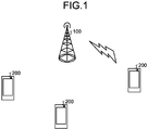
- FIG. 1 is a diagram illustrating a configuration of a radio communication system according to a first embodiment.
- the radio communication system illustrated in FIG. 1 includes a base station device 100 and a plurality of user terminal devices 200.
- the base station device 100 transmits signals including, for example, eMBB data and URLLC data to the user terminal devices 200. Namely, the base station device 100 allocates resources constituted of time and frequency to the eMBB data and the URLLC data addressed to each of the plurality of user terminal devices 200 and then generates a transmission signal.
- the base station device 100 provides an area (hereinafter, referred to as an "URLLC area") that is temporarily reserved, as an area in which URLLC data is to be arranged, in a resource area to which eMBB data is allocated and then allocates, if URLLC data to be transmitted is present, a resource of the URLLC area to the subject URLLC data. Then, the base station device 100 arranges, in the URLLC area, an indication signal indicating whether the resource of the URLLC area has been allocated to the URLLC data.
- an area hereinafter, referred to as an "URLLC area”
- the resource of the URLLC area is allocated to the URLLC data and this state is notified by the indication signal. Furthermore, if the URLLC data to be transmitted is not present, the resource of the URLLC area is allocated to the eMBB data and information indicating that the URLLC data is not transmitted is notified by the indication signal.
- Each of the user terminal devices 200 receives a signal including eMBB data and URLLC data that are transmitted from the base station device 100. Specifically, the user terminal devices 200 are classified into devices that use a service related to eMBB, devices that use a service related to URLLC, and devices that use services related to both eMBB and URLLC. Each of the user terminal devices 200 that uses the service related to eMBB specifies, based on a control signal and an indication signal included in a reception signal, eMBB data addressed to the own device and then demodulates the eMBB data.
- each of the user terminal devices 200 that uses a service related to URLLC determines, based on the indication signal included in the reception signal, whether URLLC data is included in the reception signal and then demodulates, based on the control signal if the URLLC data is included, the URLLC data addressed to the own device. Furthermore, each of the user terminal devices 200 that uses a service related to both eMBB and URLLC demodulates eMBB data and then demodulates URLLC data in a similar manner described above.
- FIG. 2 is a block diagram illustrating a configuration of the base station device 100 according to the first embodiment.
- the base station device 100 illustrated in FIG. 2 includes a processor 100a, a memory 100b, and a radio transmission unit 100c.
- the processor 100a includes, for example, a central processing unit (CPU), a field programmable gate array (FPGA), or a digital signal processor (DSP), or the like and performs overall control of the base station device 100.
- the processor 100a includes a scheduler unit 110, an eMBB data generating unit 120, an URLLC data generating unit 130, an indication signal generating unit 140, a control signal generating unit 150, a mapping unit 160, an inverse Fast Fourier transformation (IFFT) unit 170, and a cyclic prefix (CP) attaching unit 180.
- IFFT inverse Fast Fourier transformation
- CP cyclic prefix
- the scheduler unit 110 performs scheduling that allocates resources to eMBB data and URLLC data addressed to the plurality of user terminal devices 200. Specifically, the scheduler unit 110 estimates, for example, a channel state between each of the plurality of user terminal devices 200 and performs eMBB scheduling that decides, in accordance with the channel state, a resource to be allocated to eMBB data that is addressed to each of the user terminal devices 200. Furthermore, the scheduler unit 110 determines whether URLLC data addressed to one of the user terminal devices 200 is generated and performs, if the URLLC data has been generated, URLLC scheduling that decides a resource to be allocated to the URLLC data.
- the scheduler unit 110 arranges, at the time of URLLC scheduling, URLLC data in an URLLC area that is provided in the resource area to which the eMBB data is allocated.
- the resource for a transmission signal has an eMBB control channel area in which an eMBB control signal is arranged and an eMBB data area in which eMBB data is arranged; however, an URLLC area that is temporarily reserved as an area in which the URLLC data is to be arranged is provided in the eMBB data area.
- the scheduler unit 110 allocates a resource to be used for the URLLC area to the URLLC data.
- the eMBB data generating unit 120 generates, in accordance with eMBB scheduling performed by the scheduler unit 110, eMBB data to be addressed to each of the user terminal devices 200. Namely, the eMBB data generating unit 120 encodes and modulates the eMBB data addressed to each of the user terminal devices 200.
- the URLLC data generating unit 130 generates, in accordance with URLLC scheduling performed by the scheduler unit 110, URLLC data addressed to each of the user terminal devices 200. Namely, the URLLC data generating unit 130 encodes and modulates the URLLC data addressed to each of the user terminal devices 200.
- the indication signal generating unit 140 generates, in accordance with the result of determination whether URLLC scheduling has been performed by the scheduler unit 110, an indication signal indicating whether URLLC data is present. Namely, if URLLC data to be transmitted is not present and if the URLLC data is not arranged in an URLLC area, the indication signal generating unit 140 generates an indication signal indicating that URLLC data is not present. Furthermore, if URLLC data to be transmitted is present and if the URLLC data is arranged in an URLLC area, the indication signal generating unit 140 indicates that the URLLC data to be transmitted is present and then generates an indication signal that specifies a resource to be allocated to the URLLC data that is addressed to each of the user terminal devices 200.
- the indication signal generating unit 140 generates an indication signal that includes 1 bit indicating whether URLLC data is present and N bits (N is an integer equal to or greater than two) that specifies, in a case where URLLC data is present, a resource to be allocated to the subject URLLC data.
- the control signal generating unit 150 generates a control signal of each of eMBB and URLLC in accordance with eMBB scheduling and URLLC scheduling performed by the scheduler unit 110. Specifically, the control signal generating unit 150 generates an eMBB control signal including information for specifying a resource to be allocated to eMBB data addressed to each of the user terminal devices 200 and information indicating a coding rate of eMBB data, a modulation scheme of eMBB data, transmission power of eMBB data, and the like. Furthermore, if URLLC data is arranged in an URLLC area, the control signal generating unit 150 generates an URLLC control signal including information indicating a coding rate, a modulation scheme of URLLC data, transmission power of URLLC data, and the like.
- the mapping unit 160 maps eMBB data, URLLC data, an indication signal, and a control signal and generates a transmission signal. Namely, the mapping unit 160 arranges the eMBB data, the URLLC data, the indication signal, and the control signal in the resources in accordance with scheduling.
- the mapping unit 160 generates a transmission signal in which the resources illustrated in, for example, FIG. 3 have been allocated.
- FIG. 3 illustrates a specific example of allocating resources having, for example, a frequency bandwidth corresponding to the number of predetermined subcarriers and duration of time corresponding to a single TTI.
- the resource of this TTI includes an eMBB control channel area 301 and an eMBB data area 302.
- URLLC areas 311 to 313 that are temporarily reserved as areas in each of which URLLC data is to be arranged is provided in the eMBB data area 302.
- indication signals 321 to 323 an URLLC control signal 331 and URLLC data 332 are mapped.
- the mapping unit 160 maps the eMBB control signal generated by the control signal generating unit 150 to the eMBB control channel area 301 and maps the eMBB data generated by the eMBB data generating unit 120 to the eMBB data area 302. Furthermore, if URLLC scheduling has been performed, the mapping unit 160 maps both of the URLLC control signal 331 generated by the control signal generating unit 150 and the URLLC data 332 generated by the URLLC data generating unit 130 onto the URLLC areas 311 to 313. Furthermore, the mapping unit 160 maps the indication signals 321 to 323 generated by the indication signal generating unit 140 onto the URLLC areas 311 to 313, respectively.
- each of the indication signals 321 and 322 includes 1 bit indicating that URLLC data is present and N bits specifying URLLC data addressed to each of the user terminal devices 200.
- the indication signal 321 includes N bits that specify the frequency bands of the corresponding pieces of URLLC data addressed to the UEs #1 to #3.
- the indication signal 323 includes only 1 bit indicating that URLLC data is not present.
- eMBB data is mapped in the rest of the area.
- the eMBB data is mapped in the entire of the URLLC area 313. In this way, if URLLC data to be transmitted is not present, because eMBB data is mapped to the URLLC areas 311 to 313, it is possible to effectively use the resources. In particular, because eMBB data is arranged in free areas in the URLLC areas 311 to 313, it is possible to allocate the maximum amount of resources to eMBB data and thus it is possible to increase the capacity based on eMBB.
- the IFFT unit 170 performs inverse Fast Fourier transformation on the transmission signal generated by the mapping unit 160 and generates a transmission signal in time domain. Then, the IFFT unit 170 outputs the transmission signal to the CP attaching unit 180.
- the CP attaching unit 180 attaches, in units of symbols, CP to the transmission signal output from the IFFT unit 170. Then, the CP attaching unit 180 outputs, to the radio transmission unit 100c, the transmission signal to which the CP has been attached.
- the memory 100b includes, for example, a random access memory (RAM), a read only memory (ROM), or the like and stores various kinds of information when a process is performed by the processor 100a.
- RAM random access memory
- ROM read only memory
- the radio transmission unit 100c performs, on the transmission signal output from the CP attaching unit 180, a radio transmission process, such as digital/analog (D/A) conversion and up-conversion. Then, the radio transmission unit 100c transmits the transmission signal via an antenna.
- a radio transmission process such as digital/analog (D/A) conversion and up-conversion.
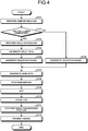
- the scheduler unit 110 performs eMBB scheduling in which the resource to be allocated to the eMBB data addressed to each of the user terminal devices 200, a coding rate, and a modulation scheme are decided (Step S101).
- the eMBB scheduling mentioned here is performed based on, for example, a channel state of a downlink reported from each of the user terminal devices 200.
- pieces of eMBB data addressed to each of the user terminal devices 200 are arranged in the eMBB data area in each TTI.
- Step S102 it is determined, by the scheduler unit 110, whether URLLC data to be addressed to one of the user terminal devices 200 has been generated. Based on this determination result, if URLLC data to be transmitted is generated (Yes at Step S102), the URLLC scheduling for deciding a resource to be allocated to the URLLC data, a coding rate, and a modulation scheme is performed by the scheduler unit 110 (Step S103).
- the URLLC scheduling is performed based on, for example, a channel state of a downlink reported from each of the user terminal devices 200.
- pieces of URLLC data addressed to the corresponding user terminal devices 200 are arranged in the URLLC areas provided in the eMBB data area in each TTI.
- Step S104 URLLC data is encoded and modulated by the URLLC data generating unit 130 by using the coding rate and the modulation scheme decided by the URLLC scheduling. Furthermore, an indication signal that indicates that URLLC data is present and that specifies the resource of the URLLC area that has been allocated to the URLLC data that is addressed to each of the user terminal devices 200 is generated by the indication signal generating unit 140 (Step S105) .
- Step S106 based on the result of determination obtained at Step S102, if URLLC data to be transmitted is not generated (No at Step S102), the result of the eMBB scheduling is notified to the eMBB data generating unit 120, the indication signal generating unit 140, and the control signal generating unit 150. Then, an indication signal indicating that URLLC data is not present is generated by the indication signal generating unit 140 (Step S106).
- eMBB data to be arranged in the eMBB data area is generated by the eMBB data generating unit 120 (Step S107). Namely, eMBB data is encoded and modulated by the eMBB data generating unit 120 by using the coding rate and the modulation scheme decided by the eMBB scheduling.
- URLLC data is arranged in an URLLC area
- transmission of eMBB data that was scheduled to be arranged in this area may also be stopped.
- orthogonalize URLLC data and eMBB data by using different codes or sequences (for example, Zadoff-Chu sequence) and arrange the URLLC data and the eMBB data in the same area.
- codes or sequences for example, Zadoff-Chu sequence
- these pieces of data interfere with each other; however, it is possible to reduce interference by using a technology, such as minimum mean square error-interference rejection combining (MMSE-IRC), symbol level interference cancellation (SLIC), and interference measurement (interference aware detection).
- MMSE-IRC minimum mean square error-interference rejection combining
- SLIC symbol level interference cancellation
- interference measurement interference aware detection
- the resource that is located in the eMBB data area allocated to the eMBB data addressed to each of the user terminal devices 200 is specified by the control signal generating unit 150 and a control signal that notifies of the coding rate of the eMBB data, the modulation scheme of the eMBB data, the transmission power of the eMBB data, and the like is generated by the control signal generating unit 150.
- a control signal that notifies of the coding rate of the URLLC data, the modulation scheme of the URLLC data, the transmission power of the URLLC data, and the like is generated by the control signal generating unit 150.
- the eMBB data, the URLLC data, the indication signal, and the control signal are mapped to each of the areas in TTI by the mapping unit 160 (Step S108). Namely, as illustrated in FIG. 3 , the eMBB control signal is mapped to the eMBB control channel area 301 and the eMBB data is mapped to the eMBB data area 302. Furthermore, if URLLC data is generated, the URLLC control signal and the URLLC data are mapped to the URLLC areas 311 to 313. Then, an indication signal indicating whether URLLC data is present is mapped to each of the URLLC areas 311 to 313. Consequently, a transmission signal is generated.
- the transmission signal is subjected to inverse Fast Fourier transformation by the IFFT unit 170 (Step S109) and transformed to a transmission signal in time domain. Then, a CP is attached, in units of symbols, to the transmission signal by the CP attaching unit 180 (Step S110) and a radio transmission process is performed on the transmission signal by the radio transmission unit 100c (Step S111). Thereafter, the transmission signal is transmitted to the user terminal device 200 via the antenna (Step S112).
- an URLLC area that is used to arrange URLLC data is provided in the eMBB; if URLLC data is present, the URLLC data is arranged in the URLLC area; and if URLLC data is not present, eMBB data is arranged in the URLLC area. Then, an indication signal indicating whether the URLLC data has been arranged in the URLLC area is arranged in each of the URLLC areas. Consequently, if URLLC data is generated, it is possible to transmit the URLLC data in low latency, whereas, if the URLLC data is not generated, it is possible to use the resource of the URLLC area in order to transmit the eMBB data. As the result, regardless whether URLLC data is present, it is possible to prevent the resources from being wasted and thus it is possible to efficiently use the resources.
- FIG. 5 is a block diagram illustrating a configuration of the user terminal device 200 according to the first embodiment.
- the user terminal device 200 illustrated in FIG. 5 is a user terminal device that uses a service related to eMBB and includes a radio receiving unit 200a, a processor 200b, and a memory 200c.
- the radio receiving unit 200a receives a signal via an antenna and performs, on a reception signal, a radio reception process, such as down-conversion, and analog/digital (A/D) conversion. Then, the radio receiving unit 200a outputs the reception signal to the processor 200b.
- a radio reception process such as down-conversion, and analog/digital (A/D) conversion. Then, the radio receiving unit 200a outputs the reception signal to the processor 200b.
- the processor 200b includes, for example, a CPU, an FPGA, a DSP, or the like and performs overall control of the user terminal device 200. Specifically, the processor 200b includes a CP removing unit 210, a fast Fourier transformation (FFT) unit 220, an indication signal demodulating unit 230, a control signal demodulating unit 240, and an eMBB data demodulating unit 250.
- FFT fast Fourier transformation
- the CP removing unit 210 removes a CP attached, in units of symbols, to a reception signal. Then, the CP removing unit 210 outputs, to the FFT unit 220, a reception signal from which the CP has been removed.
- the FFT unit 220 performs fast Fourier transformation on the reception signal output form the CP removing unit 210 and transforms the signal to a reception signal in frequency domain. Then, the FFT unit 220 outputs the reception signal to the indication signal demodulating unit 230, the control signal demodulating unit 240, and the eMBB data demodulating unit 250.
- the indication signal demodulating unit 230 demodulates the indication signals arranged in the URLLC area in the reception signal. Namely, because the positions of the indication signals in the URLLC area and the URLLC area are already known, the indication signal demodulating unit 230 demodulates the indication signal in each of the URLLC areas. Consequently, the indication signal demodulating unit 230 grasps whether URLLC data is included in each of the URLLC areas. Furthermore, if URLLC data is included in an URLLC area, the indication signal demodulating unit 230 specifies, based on the indication signal, the resource allocated to the URLLC data.
- the control signal demodulating unit 240 demodulates the control signal arranged in the eMBB control channel area in the reception signal. Namely, the control signal demodulating unit 240 demodulates the eMBB control signal and acquires information on the resource allocated to the eMBB data that is addressed to the own device and information on the coding rate of the eMBB data, the modulation scheme of the eMBB data, and the like.
- the eMBB data demodulating unit 250 demodulates the eMBB data arranged in the eMBB data area in the reception signal. At this time, the eMBB data demodulating unit 250 excludes, from the eMBB data area based on the demodulation result of the indication signal, the area in which the URLLC data has been arranged and specifies, from the eMBB data area in which the URLLC data has been excluded and based on the demodulation result of the control signal, the resource of the eMBB data that is addressed to the own device. Then, the eMBB data demodulating unit 250 demodulates the eMBB data addressed to the own device based on the coding rate, the modulation scheme, and the like indicated by the control signal.
- the eMBB data demodulating unit 250 does not need to exclude, from the eMBB data area, the area in which the URLLC data has been arranged. This is because that, if the eMBB data and the URLLC data are orthogonalized by codes or sequences, eMBB data is multiplexed, by using another code or sequence, in the time domain and the frequency domain in which the URLLC data is arranged.
- the signal from the base station device 100 is received via the antenna (Step S201) and a radio reception process is performed on the reception signal by the radio receiving unit 200a (Step S202). Then, the CP attached to the reception signal in units of symbols is removed by the CP removing unit 210 (Step S203) the reception signal is subjected to fast Fourier transformation by the FFT unit 220 (Step S204), thereby a reception signal in frequency domain is obtained.
- the indication signal arranged in the URLLC area is demodulated by the indication signal demodulating unit 230 (Step S205). Consequently, it is determined whether URLLC data is included in the URLLC area and, if the URLLC data is included, the position of the URLLC data in the URLLC area is specified. In other words, the area that is except for the resource allocated to the URLLC data and in which the eMBB data is actually arranged is specified in the eMBB data area.
- the control signal arranged in the eMBB control channel area in the reception signal is demodulated by the control signal demodulating unit 240 (Step S206); the resource allocated to the eMBB data addressed to the own devices is specified; and the coding rate of the eMBB data, the modulation scheme of the eMBB data, and the like are specified. Consequently, the eMBB data addressed to the own device is acquired from the reception signal and is demodulated by the eMBB data demodulating unit 250 (Step S207). At this time, based on the demodulation result of the indication signal, the eMBB data addressed to the own device may also be acquired from the area in which the resource allocated to the URLLC data has been removed.
- the eMBB data addressed to the own device may also be acquired from the entire eMBB data area including the resource that has been allocated to the URLLC data.
- FIG. 7 is a block diagram illustrating a configuration of the other user terminal device 200 according to the first embodiment.
- the user terminal device 200 illustrated in FIG. 7 is a user terminal device that uses a service related to URLLC and includes, similarly to the user terminal device 200 illustrated in FIG. 5 , the radio receiving unit 200a, the processor 200b, and the memory 200c.
- the processor 200b in the user terminal device 200 illustrated in FIG. 7 includes, instead of the eMBB data demodulating unit 250 illustrated in FIG. 5 , an URLLC data demodulating unit 260.
- the URLLC data demodulating unit 260 determines that, based on the demodulation result of the indication signal, the URLLC data addressed to the own device is included in the reception signal, the URLLC data demodulating unit 260 demodulates the URLLC data that is addressed to the own device and that is arranged in the URLLC area in the reception signal. At this time, the URLLC data demodulating unit 260 specifies, from the URLLC area based on the demodulation result of the indication signal, the resource for the URLLC data addressed to the own device.
- the URLLC data demodulating unit 260 demodulates the URLLC data addressed to the own device based on the coding rate, the modulation scheme, and the like indicated by the URLLC control signal that is demodulated by the control signal demodulating unit 240.
- FIG. 8 a reception process performed by the user terminal device 200 according to URLLC configured described above will be described with reference to the flowchart illustrated in FIG. 8 .
- FIG. 8 the same processes as those illustrated in FIG. 6 are assigned the same reference numerals and descriptions thereof in detail will be omitted.
- a reception signal in the frequency domain is obtained from an antenna via the radio receiving unit 200a, the CP removing unit 210, and the FFT unit 220 (Steps S201 to S204). Then, the indication signal arranged in the URLLC area in the reception signal is demodulated by the indication signal demodulating unit 230 (Step S205) and it is determined whether the URLLC data is included in the URLLC area (Step S301).
- the process is ended because the URLLC data addressed to the own device is not present.
- the URLLC control signal is demodulated by the control signal demodulating unit 240 (Step S302). Namely, because the resources allocated to the control signal and the URLLC data addressed to the own device are specified based on the demodulation result of the indication signal, the URLLC control signal addressed to the own device is demodulated by the control signal demodulating unit 240. Consequently, the coding rate, the modulation scheme, or the like of the URLLC data addressed to the own device are specified.
- the URLLC data addressed to the own device is acquired, by the URLLC data demodulating unit 260 based on the demodulation result of the indication signal, from the reception signal and the URLLC data is demodulated based on the demodulation result of the control signal (Step S303).
- the URLLC area that is temporarily reserved as an area in which the URLLC data is arranged is provided in the eMBB data area and, if URLLC data is generated, the URLLC data is transmitted by using the resource of the URLLC area. Furthermore, an indication signal indicating whether the URLLC data is present is arranged in the URLLC area. Consequently, if URLLC data is generated, it is possible to promptly transmit the URLLC data without any delay and, if URLLC data is not generated, it is possible to transmit the eMBB data by using the resource of the URLLC area. Furthermore, the user terminal device on the reception side can grasp whether the URLLC data is present based on the indication signal and thus reliably acquire the URLLC data to be addressed to the own device from the reception signal. As the result, it is possible to efficiently use the resources while maintaining high reliability and low latency of the URLLC data.
- the user terminal devices 200 related to eMBB and the user terminal devices 200 related to URLLC are separately described; however, the single user terminal device 200 may also demodulate both of the eMBB data and the URLLC data.
- the processor 200b in the user terminal device 200 includes both of the eMBB data demodulating unit 250 illustrated in FIG. 5 and the URLLC data demodulating unit 260 illustrated in FIG. 7 .
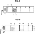
- the URLLC area is provided in the eMBB data area; however, the entire eMBB data area may also be the URLLC area. Namely, for example, as illustrated in FIG. 9 , a single TTI is divided into a plurality of short TTIs (hereinafter, referred to as a "short TTI") and all of the short TTIs except for the short TTI that includes the eMBB control channel may also be used as URLLC areas 341.
- an indication signal 342 arranged in each of the URLLC areas 341 may also be a 1-bit signal indicating whether the URLLC data is included in each of the URLLC areas 341.
- the information that specifies the resource allocated to the URLLC data 332 addressed to each of the user terminal devices 200 is included in the URLLC control signal 331.
- the characteristic of a second embodiment is that, if URLLC data is included in a reception signal, a user terminal device estimates transmission power for each subcarrier and specifies, based on the transmission power, a subcarrier including the URLLC data.
- the configuration of the radio communication system and the base station device 100 according to the second embodiment is the same as that of the first embodiment ( FIGS. 1 and 2 ); therefore, descriptions thereof will be omitted.
- the base station device 100 controls transmission power of the eMBB data and the URLLC data and transmits the URLLC data, in which high reliability is requested, by using transmission power that is greater than that of the eMBB data.
- the mapping unit 160 arranges URLLC data in an URLLC area
- the mapping unit 160 sets the transmission power of the subcarrier in which the URLLC data is to be arranged larger than the transmission power of the subcarrier in which the eMBB data is to be arranged.
- the transmission power of the subcarrier in which URLLC data is arranged is larger than the transmission power of the subcarrier in which the eMBB data is arranged.
- FIG. 10 is a diagram illustrating a specific example of resource allocation according to the second embodiment.
- the resource illustrated in FIG. 10 has subcarriers 351 to 353 and an eMBB control channel area is provided at the top of the resource.
- the areas other than the eMBB control channel area are eMBB data areas; however, in the eMBB data area, URLLC areas 361 to 363 temporarily reserved as the areas for arranging URLLC data is provided.
- indication signals 371 to 373 are mapped and the URLLC control signal and URLLC data are mapped onto the subcarriers 351 to 353 as units.
- the URLLC data addressed to the user terminal device UE #2 is mapped onto a subcarrier 352 and the URLLC data addressed to the user terminal device UE #1 is mapped onto the subcarrier 353. Furthermore, for example, in the URLLC area 362, the URLLC data addressed to the user terminal device UE #3 is mapped onto the subcarrier 353.
- the transmission power of the URLLC data is larger than that of the eMBB data.
- the transmission power of the subcarriers 352 and 353 in each of which the URLLC data is mapped is larger than the transmission power of the subcarrier 351 in which the eMBB data is mapped.
- the transmission power of the subcarrier 353 in which the URLLC data is mapped is larger than the transmission power of the subcarriers 351 and 352 in each of which the eMBB data is mapped.
- each of the indication signals 371 to 373 is a 1-bit signal indicating whether the URLLC data is included in each of the URLLC areas 361 to 363 and thus information for specifying a subcarrier in which the URLLC data is to be mapped is not included in the indication signals 371 to 373.
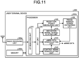
- FIG. 11 is a block diagram illustrating a configuration of the user terminal device 200 according to the second embodiment.
- the user terminal device 200 illustrated in FIG. 11 is a user terminal device that uses a service related to eMBB and includes, similarly to the user terminal device 200 illustrated in FIG. 5 , the radio receiving unit 200a, the processor 200b, and the memory 200c.
- the processor 200b in the user terminal device 200 illustrated in FIG. 11 has a configuration in which, instead of the indication signal demodulating unit 230 and the eMBB data demodulating unit 250 illustrated in FIG. 5 , an indication signal demodulating unit 410 and an eMBB data demodulating unit 440 are included and a reception power measuring unit 420 and a transmission power estimating unit 430 are added.
- the indication signal demodulating unit 410 demodulates the indication signal arranged in an URLLC area in a reception signal. Namely, because the position of the indication signal in each of the URLLC area and the URLLC area is already known, the indication signal demodulating unit 410 demodulates the indication signal in each of the URLLC areas. Consequently, the indication signal demodulating unit 410 grasps whether the URLLC data is included in each of the URLLC areas. Then, the URLLC data is included in the URLLC area, the indication signal demodulating unit 410 notifies the reception power measuring unit 420 and the eMBB data demodulating unit 440 of this state.
- the reception power measuring unit 420 measures the reception power for each subcarrier in the URLLC area in the reception signal.
- the transmission power estimating unit 430 estimates the transmission power for each subcarrier based on the reception power for each subcarrier measured by the reception power measuring unit 420. Specifically, the transmission power estimating unit 430 estimates, for example, the propagation loss between the base station device 100 and the user terminal device 200 by using the reference signal and estimates the transmission power at the base station device 100 based on the reception power and the propagation loss.
- the eMBB data demodulating unit 440 demodulates the eMBB data arranged in the eMBB data area in the reception signal. At this time, if the eMBB data demodulating unit 440 receives a notification indicating that the URLLC data is included in the URLLC area from the indication signal demodulating unit 410, the eMBB data demodulating unit 440 specifies, based on the transmission power for each subcarrier, the subcarrier in which the eMBB data has been arranged. Namely, the eMBB data demodulating unit 440 compares the transmission power for each subcarrier estimated by the transmission power estimating unit 430 with a predetermined threshold.
- the eMBB data demodulating unit 440 specifies that the URLLC data has been arranged in the subcarriers in each of which the transmission power is equal to or greater than the predetermined threshold and specifies that the eMBB data has been arranged in the subcarriers in each of which the transmission power is less than the predetermined threshold. Consequently, the eMBB data demodulation unit 440 specifies the resource in which the eMBB data is arranged in the entire eMBB data area that includes the URLLC area, and demodulates the eMBB data addressed to the own device based on the demodulation result of the control signal.
- FIG. 12 a reception process performed by the user terminal device 200 related to eMBB having the configuration described above will be described with reference to the flowchart illustrated in FIG. 12 .
- FIG. 12 the same processes as those illustrated in FIG. 6 are assigned the same reference numerals and descriptions thereof in detail will be omitted.
- a reception signal in the frequency domain is obtained from the antenna via the radio receiving unit 200a, the CP removing unit 210, and the FFT unit 220 (Step S201 ⁇ S204). Then, the indication signal arranged in the URLLC area in the reception signal is demodulated by the indication signal demodulating unit 410 (Step S205) and it is determined whether the URLLC data is included in the URLLC area (Step S401).
- the reception power for each subcarrier in the URLLC area is measured by the reception power measuring unit 420 (Step S402).
- the transmission power for each subcarrier is estimated from the reception power for each subcarrier by the transmission power estimating unit 430 (Step S403). Namely, for example, the propagation loss between the base station device 100 and the user terminal device 200 is estimated and then the transmission power for each subcarrier in the base station device 100 is estimated by adding the electrical power having an amount corresponding to the propagation loss to the reception power.
- the estimation result of the transmission power is notified to the eMBB data demodulating unit 440 and the subcarrier in which the URLLC data in the URLLC area has been arranged is specified by the eMBB data demodulating unit 440 (Step S404). Specifically, the transmission power estimated for each subcarrier is compared to the predetermined threshold by the eMBB data demodulating unit 440 and it is determined that the URLLC data has been arranged in the subcarriers in each of which the transmission power is equal to or greater than the predetermined threshold. In contrast, it is determined that the eMBB data has been arranged in the subcarriers in each of which the transmission power in the URLLC area is less than the predetermined threshold. Consequently, in also the case where the URLLC data in the URLLC area is included, the area in which the eMBB data in the eMBB data area is arranged is specified.
- the control signal that has been arranged in the eMBB control channel area in the reception signal is demodulated by the control signal demodulating unit 240 (Step S206) and the resource allocated to the eMBB data that is addressed to the own device is specified. Furthermore, the eMBB data addressed to the own device is acquired from the reception signal and demodulated by the eMBB data demodulating unit 440 (Step S207).
- the resource allocated to the eMBB data addressed to the own device is specified from the entire eMBB data area and then the eMBB data addressed to the own device is demodulated by the eMBB data demodulating unit 440.
- the URLLC area that is temporarily reserved as the area for arranging the URLLC data is provided in the eMBB data area and, if URLLC data is generated, the URLLC data is transmitted by using the resource of the URLLC area. Furthermore, in the URLLC area, the indication signal indicating whether the URLLC data is present is arranged. Consequently, if URLLC data is generated, it is possible to promptly transmit the URLLC data without delay and, if URLLC data is not generated, it is possible to transmit eMBB data by using the resource of the URLLC area.
- the user terminal device on the reception side estimates the transmission power for each subcarrier in the URLLC area and specifies, based on the transmission power, the subcarrier in which the URLLC data has been arranged. Consequently, the information for specifying the resource that is used to arrange the URLLC data does not need to be included in the indication signal and thus it is possible to reduce the size of the indication signal.
- the user terminal device 200 related to URLLC has been described; however, similarly to the user terminal device 200 related to eMBB, the user terminal device 200 related to URLLC also specifies, from the transmission power for each subcarrier, the subcarrier in which the URLLC data has been arranged.
- the indication signal may also be transmitted separated from eMBB data and URLLC data.
- the indication signal may also be transmitted by, for example, dynamic signaling, such as physical downlink control channel (PDCCH) signaling, or may also be transmitted by quasi-static signaling, such as radio resource control (RRC) signaling.
- dynamic signaling such as physical downlink control channel (PDCCH) signaling
- RRC radio resource control
Landscapes
- Engineering & Computer Science (AREA)
- Signal Processing (AREA)
- Computer Networks & Wireless Communication (AREA)
- Mobile Radio Communication Systems (AREA)
- Physics & Mathematics (AREA)
- Discrete Mathematics (AREA)
- General Physics & Mathematics (AREA)
- Mathematical Physics (AREA)
Abstract
Description
- The embodiments discussed herein are related to a base station device, a terminal device, and a transmission method.
- In recent years, in the 3rd Generation Partnership Project (3GPP) that is the standards organization related to radio communication systems, studies have been conducted on the fifth generation mobile communication system (5G). In the fifth generation mobile communication systems, services conforming to eMBB (enhanced mobile broadband), mMTC (massive machine type communications), URLLC (Ultra Reliability and Low Latency Communications), and the like are going to be started.
- For example, eMBB responds to a service of transmission of large-volume data, such as moving image data. In contrast, URLLC responds to a service in which high-reliable and low-latency communication is needed, such as automatic operations or telesurgery. In order to implement these services, discussions are actively conducted on how to set communication parameters, such as Transmission Time Interval (TTI), that is the duration of time represented by, for example, flames or subframes.
- Specifically, for example, when eMBB data and URLLC data are transmitted by using the same frequency band, it is conceivable to multiplex the eMBB data and the URLLC data by using time-division multiplexing or frequency-division multiplexing. At this time, because a low latency is needed for the URLLC data, a large reduction in TTI of URLLC compared to TTI of eMBB is studied.
-
- Non-Patent Document 1: LG Electronics, "Handling URLLC in new RAT", 3GPP TSG RAN WG1 Meeting #86, R1-166886, August 2016
- Non-Patent Document 2: NTT DOCOMO, INC., "On coexistence of eMBB and URLLC", 3GPP TSG RAN WG1 Meeting #86, R1-167391, August 2016
- Non-Patent Document 3: Samsung, "Discussion on URLLC support in NR", 3GPP TSG RAN WG1 Meeting #86, R1-166759, August 2016
- However, when eMBB data and URLLC data are multiplexed in the same frequency band, there is a problem in that the efficiency of using time and frequency resources is reduced. Specifically, because URLLC data is transmitted to control, for example, automatic operations, URLLC data to be transmitted is not always present and, accordingly, intermittent transmission occurs in URLLC data. Nevertheless, if time and frequency resources are fixedly allocated to URLLC data, the resources allocated to the URLLC data are wasted when URLLC data to be transmitted is not present.
- The disclosed technology has been made in consideration of the above-described aspect, and it has an object to provide a base station device, a terminal device, and a transmission method that can efficiently use the resources.
- According to an aspect of an embodiment, a base station device includes: a first generating unit that generates first data; a second generating unit that generates second data that is transmitted in low latency compared to the first data; an indication signal generating unit that generates an indication signal indicating whether the second data is generated by the second generating unit; a mapping unit that provides a temporary area that is temporarily reserved as an area in which the second data is to be arranged in a resource area in which the first data is arranged, and that arranges, when the second data is generated by the second generating unit, the second data in the temporary area to generate a transmission signal; and a transmitter that transmits the indication signal generated by the indication signal generating unit and the transmission signal generated by the mapping unit.
- According to an aspect of an embodiment of the base station device, the terminal device, and the transmission method disclosed in the present application, an advantage is provided in that it is possible to efficiently use the resources.
-
-
FIG. 1 is a diagram illustrating a configuration of a radio communication system according to a first embodiment. -
FIG. 2 is a block diagram illustrating a configuration of a base station device according to the first embodiment. -
FIG. 3 is a diagram illustrating a specific example of resource allocation according to the first embodiment. -
FIG. 4 is a flowchart illustrating a transmission process according to the first embodiment. -
FIG. 5 is a block diagram illustrating a configuration of a user terminal device according to the first embodiment. -
FIG. 6 is a flowchart illustrating a reception process according to the first embodiment. -
FIG. 7 is a block diagram illustrating a configuration of another user terminal device according to the first embodiment. -
FIG. 8 is a flowchart illustrating another reception process according to the first embodiment. -
FIG. 9 is a diagram illustrating another specific example of resource allocation according to the first embodiment. -
FIG. 10 is a diagram illustrating a specific example of resource allocation according to a second embodiment. -
FIG. 11 is a block diagram illustrating a configuration of a user terminal device according to the second embodiment. -
FIG. 12 is a flowchart illustrating a reception process according to the second embodiment. - Preferred embodiments of the present invention will be explained with reference to accompanying drawings. Furthermore, the present invention is not limited to the embodiments.
-
FIG. 1 is a diagram illustrating a configuration of a radio communication system according to a first embodiment. The radio communication system illustrated inFIG. 1 includes abase station device 100 and a plurality ofuser terminal devices 200. - The
base station device 100 transmits signals including, for example, eMBB data and URLLC data to theuser terminal devices 200. Namely, thebase station device 100 allocates resources constituted of time and frequency to the eMBB data and the URLLC data addressed to each of the plurality ofuser terminal devices 200 and then generates a transmission signal. - At this time, the
base station device 100 provides an area (hereinafter, referred to as an "URLLC area") that is temporarily reserved, as an area in which URLLC data is to be arranged, in a resource area to which eMBB data is allocated and then allocates, if URLLC data to be transmitted is present, a resource of the URLLC area to the subject URLLC data. Then, thebase station device 100 arranges, in the URLLC area, an indication signal indicating whether the resource of the URLLC area has been allocated to the URLLC data. - Thus, if the URLLC data to be transmitted is present, the resource of the URLLC area is allocated to the URLLC data and this state is notified by the indication signal. Furthermore, if the URLLC data to be transmitted is not present, the resource of the URLLC area is allocated to the eMBB data and information indicating that the URLLC data is not transmitted is notified by the indication signal.
- Each of the user
terminal devices 200 receives a signal including eMBB data and URLLC data that are transmitted from thebase station device 100. Specifically, theuser terminal devices 200 are classified into devices that use a service related to eMBB, devices that use a service related to URLLC, and devices that use services related to both eMBB and URLLC. Each of theuser terminal devices 200 that uses the service related to eMBB specifies, based on a control signal and an indication signal included in a reception signal, eMBB data addressed to the own device and then demodulates the eMBB data. - Furthermore, each of the
user terminal devices 200 that uses a service related to URLLC determines, based on the indication signal included in the reception signal, whether URLLC data is included in the reception signal and then demodulates, based on the control signal if the URLLC data is included, the URLLC data addressed to the own device. Furthermore, each of theuser terminal devices 200 that uses a service related to both eMBB and URLLC demodulates eMBB data and then demodulates URLLC data in a similar manner described above. -
FIG. 2 is a block diagram illustrating a configuration of thebase station device 100 according to the first embodiment. Thebase station device 100 illustrated inFIG. 2 includes aprocessor 100a, amemory 100b, and a radio transmission unit 100c. - The
processor 100a includes, for example, a central processing unit (CPU), a field programmable gate array (FPGA), or a digital signal processor (DSP), or the like and performs overall control of thebase station device 100. Specifically, theprocessor 100a includes ascheduler unit 110, an eMBB data generating unit 120, an URLLCdata generating unit 130, an indicationsignal generating unit 140, a controlsignal generating unit 150, amapping unit 160, an inverse Fast Fourier transformation (IFFT) unit 170, and a cyclic prefix (CP) attachingunit 180. - The
scheduler unit 110 performs scheduling that allocates resources to eMBB data and URLLC data addressed to the plurality ofuser terminal devices 200. Specifically, thescheduler unit 110 estimates, for example, a channel state between each of the plurality ofuser terminal devices 200 and performs eMBB scheduling that decides, in accordance with the channel state, a resource to be allocated to eMBB data that is addressed to each of theuser terminal devices 200. Furthermore, thescheduler unit 110 determines whether URLLC data addressed to one of theuser terminal devices 200 is generated and performs, if the URLLC data has been generated, URLLC scheduling that decides a resource to be allocated to the URLLC data. - The
scheduler unit 110 arranges, at the time of URLLC scheduling, URLLC data in an URLLC area that is provided in the resource area to which the eMBB data is allocated. Namely, the resource for a transmission signal has an eMBB control channel area in which an eMBB control signal is arranged and an eMBB data area in which eMBB data is arranged; however, an URLLC area that is temporarily reserved as an area in which the URLLC data is to be arranged is provided in the eMBB data area. Thus, if URLLC data to be transmitted is generated, thescheduler unit 110 allocates a resource to be used for the URLLC area to the URLLC data. - The eMBB data generating unit 120 generates, in accordance with eMBB scheduling performed by the
scheduler unit 110, eMBB data to be addressed to each of theuser terminal devices 200. Namely, the eMBB data generating unit 120 encodes and modulates the eMBB data addressed to each of theuser terminal devices 200. - The URLLC
data generating unit 130 generates, in accordance with URLLC scheduling performed by thescheduler unit 110, URLLC data addressed to each of theuser terminal devices 200. Namely, the URLLCdata generating unit 130 encodes and modulates the URLLC data addressed to each of theuser terminal devices 200. - The indication
signal generating unit 140 generates, in accordance with the result of determination whether URLLC scheduling has been performed by thescheduler unit 110, an indication signal indicating whether URLLC data is present. Namely, if URLLC data to be transmitted is not present and if the URLLC data is not arranged in an URLLC area, the indicationsignal generating unit 140 generates an indication signal indicating that URLLC data is not present. Furthermore, if URLLC data to be transmitted is present and if the URLLC data is arranged in an URLLC area, the indicationsignal generating unit 140 indicates that the URLLC data to be transmitted is present and then generates an indication signal that specifies a resource to be allocated to the URLLC data that is addressed to each of theuser terminal devices 200. Namely, the indicationsignal generating unit 140 generates an indication signal that includes 1 bit indicating whether URLLC data is present and N bits (N is an integer equal to or greater than two) that specifies, in a case where URLLC data is present, a resource to be allocated to the subject URLLC data. - The control
signal generating unit 150 generates a control signal of each of eMBB and URLLC in accordance with eMBB scheduling and URLLC scheduling performed by thescheduler unit 110. Specifically, the controlsignal generating unit 150 generates an eMBB control signal including information for specifying a resource to be allocated to eMBB data addressed to each of theuser terminal devices 200 and information indicating a coding rate of eMBB data, a modulation scheme of eMBB data, transmission power of eMBB data, and the like. Furthermore, if URLLC data is arranged in an URLLC area, the controlsignal generating unit 150 generates an URLLC control signal including information indicating a coding rate, a modulation scheme of URLLC data, transmission power of URLLC data, and the like. - The
mapping unit 160 maps eMBB data, URLLC data, an indication signal, and a control signal and generates a transmission signal. Namely, themapping unit 160 arranges the eMBB data, the URLLC data, the indication signal, and the control signal in the resources in accordance with scheduling. - Specifically, the
mapping unit 160 generates a transmission signal in which the resources illustrated in, for example,FIG. 3 have been allocated.FIG. 3 illustrates a specific example of allocating resources having, for example, a frequency bandwidth corresponding to the number of predetermined subcarriers and duration of time corresponding to a single TTI. As illustrated inFIG. 3 , the resource of this TTI includes an eMBBcontrol channel area 301 and aneMBB data area 302. Then,URLLC areas 311 to 313 that are temporarily reserved as areas in each of which URLLC data is to be arranged is provided in theeMBB data area 302. In theURLLC areas 311 to 313, indication signals 321 to 323, anURLLC control signal 331 andURLLC data 332 are mapped. - The
mapping unit 160 maps the eMBB control signal generated by the controlsignal generating unit 150 to the eMBBcontrol channel area 301 and maps the eMBB data generated by the eMBB data generating unit 120 to theeMBB data area 302. Furthermore, if URLLC scheduling has been performed, themapping unit 160 maps both of theURLLC control signal 331 generated by the controlsignal generating unit 150 and theURLLC data 332 generated by the URLLCdata generating unit 130 onto theURLLC areas 311 to 313. Furthermore, themapping unit 160 maps the indication signals 321 to 323 generated by the indicationsignal generating unit 140 onto theURLLC areas 311 to 313, respectively. - At this time, as illustrated in
FIG. 3 , because the URLLC data has been arranged in theURLLC areas user terminal devices 200. Namely, for example, because three pieces of URLLC data addressed to theuser terminal devices 200 ofUEs # 1 to #3 are arranged in theURLLC area 311, theindication signal 321 includes N bits that specify the frequency bands of the corresponding pieces of URLLC data addressed to theUEs # 1 to #3. In contrast, because URLLC data is not arranged in theURLLC area 313, theindication signal 323 includes only 1 bit indicating that URLLC data is not present. - Furthermore, in the
URLLC area 312, because URLLC data is mapped to a part of theURLLC area 312, eMBB data is mapped in the rest of the area. Similarly, in theURLLC area 313, because URLLC data is not mapped, the eMBB data is mapped in the entire of theURLLC area 313. In this way, if URLLC data to be transmitted is not present, because eMBB data is mapped to theURLLC areas 311 to 313, it is possible to effectively use the resources. In particular, because eMBB data is arranged in free areas in theURLLC areas 311 to 313, it is possible to allocate the maximum amount of resources to eMBB data and thus it is possible to increase the capacity based on eMBB. - A description will be given here by referring back to
FIG. 2 . The IFFT unit 170 performs inverse Fast Fourier transformation on the transmission signal generated by themapping unit 160 and generates a transmission signal in time domain. Then, the IFFT unit 170 outputs the transmission signal to theCP attaching unit 180. - The
CP attaching unit 180 attaches, in units of symbols, CP to the transmission signal output from the IFFT unit 170. Then, theCP attaching unit 180 outputs, to the radio transmission unit 100c, the transmission signal to which the CP has been attached. - The
memory 100b includes, for example, a random access memory (RAM), a read only memory (ROM), or the like and stores various kinds of information when a process is performed by theprocessor 100a. - The radio transmission unit 100c performs, on the transmission signal output from the
CP attaching unit 180, a radio transmission process, such as digital/analog (D/A) conversion and up-conversion. Then, the radio transmission unit 100c transmits the transmission signal via an antenna. - In the following, a transmission process performed by the
base station device 100 having configuration described above will be described with reference to the flowchart illustrated inFIG. 4 . - First, the
scheduler unit 110 performs eMBB scheduling in which the resource to be allocated to the eMBB data addressed to each of theuser terminal devices 200, a coding rate, and a modulation scheme are decided (Step S101). The eMBB scheduling mentioned here is performed based on, for example, a channel state of a downlink reported from each of theuser terminal devices 200. In eMBB scheduling, pieces of eMBB data addressed to each of theuser terminal devices 200 are arranged in the eMBB data area in each TTI. - Furthermore, it is determined, by the
scheduler unit 110, whether URLLC data to be addressed to one of theuser terminal devices 200 has been generated (Step S102). Based on this determination result, if URLLC data to be transmitted is generated (Yes at Step S102), the URLLC scheduling for deciding a resource to be allocated to the URLLC data, a coding rate, and a modulation scheme is performed by the scheduler unit 110 (Step S103). The URLLC scheduling is performed based on, for example, a channel state of a downlink reported from each of theuser terminal devices 200. In URLLC scheduling, pieces of URLLC data addressed to the correspondinguser terminal devices 200 are arranged in the URLLC areas provided in the eMBB data area in each TTI. - Then, the result of scheduling is notified to the eMBB data generating unit 120, the URLLC
data generating unit 130, the indicationsignal generating unit 140, and the controlsignal generating unit 150 and then pieces of URLLC data to be arranged in the URLLC areas are generated by the URLLC data generating unit 130 (Step S104). Namely, URLLC data is encoded and modulated by the URLLCdata generating unit 130 by using the coding rate and the modulation scheme decided by the URLLC scheduling. Furthermore, an indication signal that indicates that URLLC data is present and that specifies the resource of the URLLC area that has been allocated to the URLLC data that is addressed to each of theuser terminal devices 200 is generated by the indication signal generating unit 140 (Step S105) . - In contrast, based on the result of determination obtained at Step S102, if URLLC data to be transmitted is not generated (No at Step S102), the result of the eMBB scheduling is notified to the eMBB data generating unit 120, the indication
signal generating unit 140, and the controlsignal generating unit 150. Then, an indication signal indicating that URLLC data is not present is generated by the indication signal generating unit 140 (Step S106). - Furthermore, regardless whether URLLC data is present, eMBB data to be arranged in the eMBB data area is generated by the eMBB data generating unit 120 (Step S107). Namely, eMBB data is encoded and modulated by the eMBB data generating unit 120 by using the coding rate and the modulation scheme decided by the eMBB scheduling.
- Furthermore, if URLLC data is arranged in an URLLC area, transmission of eMBB data that was scheduled to be arranged in this area may also be stopped. Furthermore, it is possible to orthogonalize URLLC data and eMBB data by using different codes or sequences (for example, Zadoff-Chu sequence) and arrange the URLLC data and the eMBB data in the same area. When arranging the URLLC data and the eMBB data in the same area, these pieces of data interfere with each other; however, it is possible to reduce interference by using a technology, such as minimum mean square error-interference rejection combining (MMSE-IRC), symbol level interference cancellation (SLIC), and interference measurement (interference aware detection).
- If eMBB data has been generated, the resource that is located in the eMBB data area allocated to the eMBB data addressed to each of the
user terminal devices 200 is specified by the controlsignal generating unit 150 and a control signal that notifies of the coding rate of the eMBB data, the modulation scheme of the eMBB data, the transmission power of the eMBB data, and the like is generated by the controlsignal generating unit 150. Furthermore, if URLLC data has been generated, a control signal that notifies of the coding rate of the URLLC data, the modulation scheme of the URLLC data, the transmission power of the URLLC data, and the like is generated by the controlsignal generating unit 150. - Then, the eMBB data, the URLLC data, the indication signal, and the control signal are mapped to each of the areas in TTI by the mapping unit 160 (Step S108). Namely, as illustrated in
FIG. 3 , the eMBB control signal is mapped to the eMBBcontrol channel area 301 and the eMBB data is mapped to theeMBB data area 302. Furthermore, if URLLC data is generated, the URLLC control signal and the URLLC data are mapped to theURLLC areas 311 to 313. Then, an indication signal indicating whether URLLC data is present is mapped to each of theURLLC areas 311 to 313. Consequently, a transmission signal is generated. - The transmission signal is subjected to inverse Fast Fourier transformation by the IFFT unit 170 (Step S109) and transformed to a transmission signal in time domain. Then, a CP is attached, in units of symbols, to the transmission signal by the CP attaching unit 180 (Step S110) and a radio transmission process is performed on the transmission signal by the radio transmission unit 100c (Step S111). Thereafter, the transmission signal is transmitted to the
user terminal device 200 via the antenna (Step S112). - As described above, an URLLC area that is used to arrange URLLC data is provided in the eMBB; if URLLC data is present, the URLLC data is arranged in the URLLC area; and if URLLC data is not present, eMBB data is arranged in the URLLC area. Then, an indication signal indicating whether the URLLC data has been arranged in the URLLC area is arranged in each of the URLLC areas. Consequently, if URLLC data is generated, it is possible to transmit the URLLC data in low latency, whereas, if the URLLC data is not generated, it is possible to use the resource of the URLLC area in order to transmit the eMBB data. As the result, regardless whether URLLC data is present, it is possible to prevent the resources from being wasted and thus it is possible to efficiently use the resources.
- In the following, a configuration of the
user terminal device 200 will be described.FIG. 5 is a block diagram illustrating a configuration of theuser terminal device 200 according to the first embodiment. Theuser terminal device 200 illustrated inFIG. 5 is a user terminal device that uses a service related to eMBB and includes aradio receiving unit 200a, aprocessor 200b, and amemory 200c. - The
radio receiving unit 200a receives a signal via an antenna and performs, on a reception signal, a radio reception process, such as down-conversion, and analog/digital (A/D) conversion. Then, theradio receiving unit 200a outputs the reception signal to theprocessor 200b. - The
processor 200b includes, for example, a CPU, an FPGA, a DSP, or the like and performs overall control of theuser terminal device 200. Specifically, theprocessor 200b includes aCP removing unit 210, a fast Fourier transformation (FFT)unit 220, an indicationsignal demodulating unit 230, a control signal demodulating unit 240, and an eMBBdata demodulating unit 250. - The
CP removing unit 210 removes a CP attached, in units of symbols, to a reception signal. Then, theCP removing unit 210 outputs, to theFFT unit 220, a reception signal from which the CP has been removed. - The
FFT unit 220 performs fast Fourier transformation on the reception signal output form theCP removing unit 210 and transforms the signal to a reception signal in frequency domain. Then, theFFT unit 220 outputs the reception signal to the indicationsignal demodulating unit 230, the control signal demodulating unit 240, and the eMBBdata demodulating unit 250. - The indication
signal demodulating unit 230 demodulates the indication signals arranged in the URLLC area in the reception signal. Namely, because the positions of the indication signals in the URLLC area and the URLLC area are already known, the indicationsignal demodulating unit 230 demodulates the indication signal in each of the URLLC areas. Consequently, the indicationsignal demodulating unit 230 grasps whether URLLC data is included in each of the URLLC areas. Furthermore, if URLLC data is included in an URLLC area, the indicationsignal demodulating unit 230 specifies, based on the indication signal, the resource allocated to the URLLC data. - The control signal demodulating unit 240 demodulates the control signal arranged in the eMBB control channel area in the reception signal. Namely, the control signal demodulating unit 240 demodulates the eMBB control signal and acquires information on the resource allocated to the eMBB data that is addressed to the own device and information on the coding rate of the eMBB data, the modulation scheme of the eMBB data, and the like.
- The eMBB
data demodulating unit 250 demodulates the eMBB data arranged in the eMBB data area in the reception signal. At this time, the eMBBdata demodulating unit 250 excludes, from the eMBB data area based on the demodulation result of the indication signal, the area in which the URLLC data has been arranged and specifies, from the eMBB data area in which the URLLC data has been excluded and based on the demodulation result of the control signal, the resource of the eMBB data that is addressed to the own device. Then, the eMBBdata demodulating unit 250 demodulates the eMBB data addressed to the own device based on the coding rate, the modulation scheme, and the like indicated by the control signal. Furthermore, if the eMBB data and the URLLC data are orthogonalized by using different codes or sequences, the eMBBdata demodulating unit 250 does not need to exclude, from the eMBB data area, the area in which the URLLC data has been arranged. This is because that, if the eMBB data and the URLLC data are orthogonalized by codes or sequences, eMBB data is multiplexed, by using another code or sequence, in the time domain and the frequency domain in which the URLLC data is arranged. - In the following, a reception process performed by the
user terminal device 200 according to eMBB configured described above will be described with reference to the flowchart illustrated inFIG. 6 . - The signal from the
base station device 100 is received via the antenna (Step S201) and a radio reception process is performed on the reception signal by theradio receiving unit 200a (Step S202). Then, the CP attached to the reception signal in units of symbols is removed by the CP removing unit 210 (Step S203) the reception signal is subjected to fast Fourier transformation by the FFT unit 220 (Step S204), thereby a reception signal in frequency domain is obtained. - Because an URLLC area is provided in an eMBB data area in a reception signal and the resource of the URLLC area is already known, the indication signal arranged in the URLLC area is demodulated by the indication signal demodulating unit 230 (Step S205). Consequently, it is determined whether URLLC data is included in the URLLC area and, if the URLLC data is included, the position of the URLLC data in the URLLC area is specified. In other words, the area that is except for the resource allocated to the URLLC data and in which the eMBB data is actually arranged is specified in the eMBB data area.
- Furthermore, the control signal arranged in the eMBB control channel area in the reception signal is demodulated by the control signal demodulating unit 240 (Step S206); the resource allocated to the eMBB data addressed to the own devices is specified; and the coding rate of the eMBB data, the modulation scheme of the eMBB data, and the like are specified. Consequently, the eMBB data addressed to the own device is acquired from the reception signal and is demodulated by the eMBB data demodulating unit 250 (Step S207). At this time, based on the demodulation result of the indication signal, the eMBB data addressed to the own device may also be acquired from the area in which the resource allocated to the URLLC data has been removed. Furthermore, if the URLLC data and the eMBB data are orthogonalized by using different codes or sequences, the eMBB data addressed to the own device may also be acquired from the entire eMBB data area including the resource that has been allocated to the URLLC data.
-
FIG. 7 is a block diagram illustrating a configuration of the otheruser terminal device 200 according to the first embodiment. InFIG. 7 , components having the same configuration as those illustrated inFIG. 5 are assigned the same reference numerals and descriptions thereof in detail will be omitted. Theuser terminal device 200 illustrated inFIG. 7 is a user terminal device that uses a service related to URLLC and includes, similarly to theuser terminal device 200 illustrated inFIG. 5 , theradio receiving unit 200a, theprocessor 200b, and thememory 200c. However, theprocessor 200b in theuser terminal device 200 illustrated inFIG. 7 includes, instead of the eMBBdata demodulating unit 250 illustrated inFIG. 5 , an URLLCdata demodulating unit 260. - If the URLLC
data demodulating unit 260 determines that, based on the demodulation result of the indication signal, the URLLC data addressed to the own device is included in the reception signal, the URLLCdata demodulating unit 260 demodulates the URLLC data that is addressed to the own device and that is arranged in the URLLC area in the reception signal. At this time, the URLLCdata demodulating unit 260 specifies, from the URLLC area based on the demodulation result of the indication signal, the resource for the URLLC data addressed to the own device. Then, the URLLCdata demodulating unit 260 demodulates the URLLC data addressed to the own device based on the coding rate, the modulation scheme, and the like indicated by the URLLC control signal that is demodulated by the control signal demodulating unit 240. - In the following, a reception process performed by the
user terminal device 200 according to URLLC configured described above will be described with reference to the flowchart illustrated inFIG. 8 . InFIG. 8 , the same processes as those illustrated inFIG. 6 are assigned the same reference numerals and descriptions thereof in detail will be omitted. - Regarding the signal transmitted from the
base station device 100, a reception signal in the frequency domain is obtained from an antenna via theradio receiving unit 200a, theCP removing unit 210, and the FFT unit 220 (Steps S201 to S204). Then, the indication signal arranged in the URLLC area in the reception signal is demodulated by the indication signal demodulating unit 230 (Step S205) and it is determined whether the URLLC data is included in the URLLC area (Step S301). - If the URLLC data is not included in the URLLC area (No at Step S301), the process is ended because the URLLC data addressed to the own device is not present. In contrast, if the URLLC data is included in the URLLC area (Yes at Step S301), the URLLC control signal is demodulated by the control signal demodulating unit 240 (Step S302). Namely, because the resources allocated to the control signal and the URLLC data addressed to the own device are specified based on the demodulation result of the indication signal, the URLLC control signal addressed to the own device is demodulated by the control signal demodulating unit 240. Consequently, the coding rate, the modulation scheme, or the like of the URLLC data addressed to the own device are specified.
- Furthermore, the URLLC data addressed to the own device is acquired, by the URLLC
data demodulating unit 260 based on the demodulation result of the indication signal, from the reception signal and the URLLC data is demodulated based on the demodulation result of the control signal (Step S303). - As described above, according to the embodiment, the URLLC area that is temporarily reserved as an area in which the URLLC data is arranged is provided in the eMBB data area and, if URLLC data is generated, the URLLC data is transmitted by using the resource of the URLLC area. Furthermore, an indication signal indicating whether the URLLC data is present is arranged in the URLLC area. Consequently, if URLLC data is generated, it is possible to promptly transmit the URLLC data without any delay and, if URLLC data is not generated, it is possible to transmit the eMBB data by using the resource of the URLLC area. Furthermore, the user terminal device on the reception side can grasp whether the URLLC data is present based on the indication signal and thus reliably acquire the URLLC data to be addressed to the own device from the reception signal. As the result, it is possible to efficiently use the resources while maintaining high reliability and low latency of the URLLC data.
- Furthermore, in the first embodiment, the
user terminal devices 200 related to eMBB and theuser terminal devices 200 related to URLLC are separately described; however, the singleuser terminal device 200 may also demodulate both of the eMBB data and the URLLC data. In this case, theprocessor 200b in theuser terminal device 200 includes both of the eMBBdata demodulating unit 250 illustrated inFIG. 5 and the URLLCdata demodulating unit 260 illustrated inFIG. 7 . - Furthermore, in the first embodiment, the URLLC area is provided in the eMBB data area; however, the entire eMBB data area may also be the URLLC area. Namely, for example, as illustrated in
FIG. 9 , a single TTI is divided into a plurality of short TTIs (hereinafter, referred to as a "short TTI") and all of the short TTIs except for the short TTI that includes the eMBB control channel may also be used asURLLC areas 341. - Furthermore, as illustrated in
FIG. 9 , anindication signal 342 arranged in each of theURLLC areas 341 may also be a 1-bit signal indicating whether the URLLC data is included in each of theURLLC areas 341. In this case, the information that specifies the resource allocated to theURLLC data 332 addressed to each of theuser terminal devices 200 is included in theURLLC control signal 331. - The characteristic of a second embodiment is that, if URLLC data is included in a reception signal, a user terminal device estimates transmission power for each subcarrier and specifies, based on the transmission power, a subcarrier including the URLLC data.
- The configuration of the radio communication system and the
base station device 100 according to the second embodiment is the same as that of the first embodiment (FIGS. 1 and2 ); therefore, descriptions thereof will be omitted. However, thebase station device 100 controls transmission power of the eMBB data and the URLLC data and transmits the URLLC data, in which high reliability is requested, by using transmission power that is greater than that of the eMBB data. Specifically, when themapping unit 160 arranges URLLC data in an URLLC area, themapping unit 160 sets the transmission power of the subcarrier in which the URLLC data is to be arranged larger than the transmission power of the subcarrier in which the eMBB data is to be arranged. Thus, if the URLLC data is arranged in an URLLC area and is transmitted, the transmission power of the subcarrier in which URLLC data is arranged is larger than the transmission power of the subcarrier in which the eMBB data is arranged. -
FIG. 10 is a diagram illustrating a specific example of resource allocation according to the second embodiment. The resource illustrated inFIG. 10 hassubcarriers 351 to 353 and an eMBB control channel area is provided at the top of the resource. Furthermore, the areas other than the eMBB control channel area are eMBB data areas; however, in the eMBB data area,URLLC areas 361 to 363 temporarily reserved as the areas for arranging URLLC data is provided. In theURLLC areas 361 to 363, indication signals 371 to 373 are mapped and the URLLC control signal and URLLC data are mapped onto thesubcarriers 351 to 353 as units. - Specifically, for example, in the
URLLC area 361, the URLLC data addressed to the user terminaldevice UE # 2 is mapped onto asubcarrier 352 and the URLLC data addressed to the user terminaldevice UE # 1 is mapped onto thesubcarrier 353. Furthermore, for example, in theURLLC area 362, the URLLC data addressed to the user terminaldevice UE # 3 is mapped onto thesubcarrier 353. - Here, because the URLLC data is data in which high reliability is requested, the transmission power of the URLLC data is larger than that of the eMBB data. Thus, for example, in the
URLLC area 361, the transmission power of thesubcarriers subcarrier 351 in which the eMBB data is mapped. Similarly, for example, in theURLLC area 362, the transmission power of thesubcarrier 353 in which the URLLC data is mapped is larger than the transmission power of thesubcarriers - Namely, in each of the
URLLC areas 361 to 363, based on the transmission power for each subcarrier, it is possible to determine which one of the pieces of the eMBB data and URLLC data is mapped in thesubcarriers 351 to 353. Therefore, each of the indication signals 371 to 373 is a 1-bit signal indicating whether the URLLC data is included in each of theURLLC areas 361 to 363 and thus information for specifying a subcarrier in which the URLLC data is to be mapped is not included in the indication signals 371 to 373. -
FIG. 11 is a block diagram illustrating a configuration of theuser terminal device 200 according to the second embodiment.FIG. 11 , components having the same configuration as those illustrated inFIG. 5 are assigned the same reference numerals and descriptions thereof in detail will be omitted. Theuser terminal device 200 illustrated inFIG. 11 is a user terminal device that uses a service related to eMBB and includes, similarly to theuser terminal device 200 illustrated inFIG. 5 , theradio receiving unit 200a, theprocessor 200b, and thememory 200c. However, theprocessor 200b in theuser terminal device 200 illustrated inFIG. 11 has a configuration in which, instead of the indicationsignal demodulating unit 230 and the eMBBdata demodulating unit 250 illustrated inFIG. 5 , an indication signal demodulating unit 410 and an eMBB data demodulating unit 440 are included and a receptionpower measuring unit 420 and a transmissionpower estimating unit 430 are added. - The indication signal demodulating unit 410 demodulates the indication signal arranged in an URLLC area in a reception signal. Namely, because the position of the indication signal in each of the URLLC area and the URLLC area is already known, the indication signal demodulating unit 410 demodulates the indication signal in each of the URLLC areas. Consequently, the indication signal demodulating unit 410 grasps whether the URLLC data is included in each of the URLLC areas. Then, the URLLC data is included in the URLLC area, the indication signal demodulating unit 410 notifies the reception
power measuring unit 420 and the eMBB data demodulating unit 440 of this state. - If the reception
power measuring unit 420 receives the notification indicating that the URLLC data is included in the URLLC area from the indication signal demodulating unit 410, the receptionpower measuring unit 420 measures the reception power for each subcarrier in the URLLC area in the reception signal. - The transmission
power estimating unit 430 estimates the transmission power for each subcarrier based on the reception power for each subcarrier measured by the receptionpower measuring unit 420. Specifically, the transmissionpower estimating unit 430 estimates, for example, the propagation loss between thebase station device 100 and theuser terminal device 200 by using the reference signal and estimates the transmission power at thebase station device 100 based on the reception power and the propagation loss. - The eMBB data demodulating unit 440 demodulates the eMBB data arranged in the eMBB data area in the reception signal. At this time, if the eMBB data demodulating unit 440 receives a notification indicating that the URLLC data is included in the URLLC area from the indication signal demodulating unit 410, the eMBB data demodulating unit 440 specifies, based on the transmission power for each subcarrier, the subcarrier in which the eMBB data has been arranged. Namely, the eMBB data demodulating unit 440 compares the transmission power for each subcarrier estimated by the transmission
power estimating unit 430 with a predetermined threshold. Then, the eMBB data demodulating unit 440 specifies that the URLLC data has been arranged in the subcarriers in each of which the transmission power is equal to or greater than the predetermined threshold and specifies that the eMBB data has been arranged in the subcarriers in each of which the transmission power is less than the predetermined threshold. Consequently, the eMBB data demodulation unit 440 specifies the resource in which the eMBB data is arranged in the entire eMBB data area that includes the URLLC area, and demodulates the eMBB data addressed to the own device based on the demodulation result of the control signal. - In the following, a reception process performed by the
user terminal device 200 related to eMBB having the configuration described above will be described with reference to the flowchart illustrated inFIG. 12 . InFIG. 12 , the same processes as those illustrated inFIG. 6 are assigned the same reference numerals and descriptions thereof in detail will be omitted. - Regarding the signal transmitted from the
base station device 100, a reception signal in the frequency domain is obtained from the antenna via theradio receiving unit 200a, theCP removing unit 210, and the FFT unit 220 (Step S201∼S204). Then, the indication signal arranged in the URLLC area in the reception signal is demodulated by the indication signal demodulating unit 410 (Step S205) and it is determined whether the URLLC data is included in the URLLC area (Step S401). - If the URLLC data is included in the URLLC area (Yes at Step S401), the reception power for each subcarrier in the URLLC area is measured by the reception power measuring unit 420 (Step S402). Then, the transmission power for each subcarrier is estimated from the reception power for each subcarrier by the transmission power estimating unit 430 (Step S403). Namely, for example, the propagation loss between the
base station device 100 and theuser terminal device 200 is estimated and then the transmission power for each subcarrier in thebase station device 100 is estimated by adding the electrical power having an amount corresponding to the propagation loss to the reception power. - The estimation result of the transmission power is notified to the eMBB data demodulating unit 440 and the subcarrier in which the URLLC data in the URLLC area has been arranged is specified by the eMBB data demodulating unit 440 (Step S404). Specifically, the transmission power estimated for each subcarrier is compared to the predetermined threshold by the eMBB data demodulating unit 440 and it is determined that the URLLC data has been arranged in the subcarriers in each of which the transmission power is equal to or greater than the predetermined threshold. In contrast, it is determined that the eMBB data has been arranged in the subcarriers in each of which the transmission power in the URLLC area is less than the predetermined threshold. Consequently, in also the case where the URLLC data in the URLLC area is included, the area in which the eMBB data in the eMBB data area is arranged is specified.
- Then, if the area in which the eMBB data is arranged is specified, the control signal that has been arranged in the eMBB control channel area in the reception signal is demodulated by the control signal demodulating unit 240 (Step S206) and the resource allocated to the eMBB data that is addressed to the own device is specified. Furthermore, the eMBB data addressed to the own device is acquired from the reception signal and demodulated by the eMBB data demodulating unit 440 (Step S207).
- Furthermore, if the URLLC data is not included in the URLLC area (No at Step S401), based on the demodulation result of the control signal, the resource allocated to the eMBB data addressed to the own device is specified from the entire eMBB data area and then the eMBB data addressed to the own device is demodulated by the eMBB data demodulating unit 440.
- As described above, according to the embodiment, the URLLC area that is temporarily reserved as the area for arranging the URLLC data is provided in the eMBB data area and, if URLLC data is generated, the URLLC data is transmitted by using the resource of the URLLC area. Furthermore, in the URLLC area, the indication signal indicating whether the URLLC data is present is arranged. Consequently, if URLLC data is generated, it is possible to promptly transmit the URLLC data without delay and, if URLLC data is not generated, it is possible to transmit eMBB data by using the resource of the URLLC area. Furthermore, if URLLC data is included in the URLLC area, the user terminal device on the reception side estimates the transmission power for each subcarrier in the URLLC area and specifies, based on the transmission power, the subcarrier in which the URLLC data has been arranged. Consequently, the information for specifying the resource that is used to arrange the URLLC data does not need to be included in the indication signal and thus it is possible to reduce the size of the indication signal.
- Furthermore, in the second embodiment described above, the
user terminal device 200 related to URLLC has been described; however, similarly to theuser terminal device 200 related to eMBB, theuser terminal device 200 related to URLLC also specifies, from the transmission power for each subcarrier, the subcarrier in which the URLLC data has been arranged. - Furthermore, in each of the embodiments, a description has been given with the assumption that an indication signal is arranged in an URLLC area; however, the indication signal does not always need to be arranged in the URLLC area. Namely, if it is possible to specify the association relationship between an indication signal and an URLLC area, the indication signal may also be transmitted separated from eMBB data and URLLC data. Furthermore, the indication signal may also be transmitted by, for example, dynamic signaling, such as physical downlink control channel (PDCCH) signaling, or may also be transmitted by quasi-static signaling, such as radio resource control (RRC) signaling.
-
- 110
- SCHEDULER UNIT
- 120
- EMBB DATA GENERATING UNIT
- 130
- URLLC DATA GENERATING UNIT
- 140
- INDICATION SIGNAL GENERATING UNIT
- 150
- CONTROL SIGNAL GENERATING UNIT
- 160
- MAPPING UNIT
- 170
- IFFT UNIT
- 180
- CP ATTACHING UNIT
- 210
- CP REMOVING UNIT
- 220
- FFT UNIT
- 230, 410
- INDICATION SIGNAL DEMODULATING UNIT
- 240
- CONTROL SIGNAL DEMODULATING UNIT
- 250, 440
- EMBB DATA DEMODULATING UNIT
- 260
- URLLC DATA DEMODULATING UNIT
- 420
- RECEPTION POWER MEASURING UNIT
- 430
- TRANSMISSION POWER ESTIMATING UNIT
Claims (10)
- A base station device comprising:a first generating unit that generates first data;a second generating unit that generates second data that is transmitted in low latency compared to the first data;an indication signal generating unit that generates an indication signal indicating whether the second data is generated by the second generating unit;a mapping unit that provides a temporary area that is temporarily reserved as an area in which the second data is to be arranged in a resource area in which the first data is arranged, and that arranges, when the second data is generated by the second generating unit, the second data in the temporary area to generate a transmission signal; anda transmitter that transmits the indication signal generated by the indication signal generating unit and the transmission signal generated by the mapping unit.
- The base station device according to claim 1, wherein
the mapping unit arranges the indication signal generated by the indication signal generating unit in the temporary area to generate the transmission signal, and
the transmitter transmits the transmission signal including the indication signal. - The base station device according to claim 1, wherein the indication signal generating unit generates a 1-bit indication signal indicating whether the second data is generated by the second generating unit.
- The base station device according to claim 1, wherein, when the second data is generated by the second generating unit, the indication signal generating unit generates an indication signal that specifies a resource in which the second data is to be arranged.
- The base station device according to claim 1, wherein, when the second data is generated by the second generating unit, the mapping unit arranges a control signal including information on a coding rate and a modulation scheme of the second data in the temporary area to generate the transmission signal.
- The base station device according to claim 1, wherein, when the second data is generated by the second generating unit, the mapping unit increases transmission power of the second data larger than transmission power of the first data.
- The base station device according to claim 1, wherein the mapping unit arranges the second data in the temporary area and arranges the first data that is orthogonalized to the second data in the temporary area, to generate the transmission signal.
- A terminal device comprising:a receiver that receives a reception signal including first data and that receives an indication signal indicating whether second data that is transmitted in low latency compared to the first data is included in the reception signal;a determination unit that determines, based on the indication signal received by the receiver, whether the second data is included in a temporary area that is provided in a resource area in which the first data included in the reception signal is arranged and that is temporarily reserved as an area in which the second data is to be arranged; anda demodulating unit that demodulates, based on a determination result obtained by the determination unit, the first data or the second data.
- A radio communication system comprising:a base station device; anda terminal device, whereinthe base station device includesa first generating unit that generates first data,a second generating unit that generates second data that is transmitted in low latency compared to the first data,an indication signal generating unit that generates an indication signal indicating whether the second data is generated by the second generating unit,a mapping unit that provides a temporary area that is temporarily reserved as an area in which the second data is to be arranged in a resource area in which the first data is arranged, and that arranges, when the second data is generated by the second generating unit, the second data in the temporary area to generate a transmission signal, anda transmitter that transmits the indication signal generated by the indication signal generating unit and the transmission signal generated by the mapping unit, andthe terminal device includesa receiver that receives the indication signal and the transmission signal transmitted from the transmitter,a determination unit that determines, based on the indication signal received by the receiver, whether the second data is included in the temporary area, anda demodulating unit that demodulates, based on a determination result obtained by the determination unit, the first data or the second data.
- A transmission method comprising:generating first data;generating an indication signal indicating whether second data that is transmitted in low latency compared to the first data;providing a temporary area that is temporarily reserved as an area in which the second data is to be arranged in a resource area in which the first data is arranged, and arranging, when the second data is generated, the second data in the temporary area to generate a transmission signal; andtransmitting the indication signal and the transmission signal.
Applications Claiming Priority (1)
| Application Number | Priority Date | Filing Date | Title |
|---|---|---|---|
| PCT/JP2016/078923 WO2018061159A1 (en) | 2016-09-29 | 2016-09-29 | Base station device, terminal device, and transmission method |
Publications (2)
| Publication Number | Publication Date |
|---|---|
| EP3522650A1 true EP3522650A1 (en) | 2019-08-07 |
| EP3522650A4 EP3522650A4 (en) | 2020-05-27 |
Family
ID=61760244
Family Applications (1)
| Application Number | Title | Priority Date | Filing Date |
|---|---|---|---|
| EP16917711.0A Withdrawn EP3522650A4 (en) | 2016-09-29 | 2016-09-29 | BASE STATION DEVICE, TERMINAL DEVICE, AND TRANSMISSION METHOD |
Country Status (6)
| Country | Link |
|---|---|
| US (2) | US10750524B2 (en) |
| EP (1) | EP3522650A4 (en) |
| JP (1) | JP6782299B2 (en) |
| KR (1) | KR102227707B1 (en) |
| CN (1) | CN109792755A (en) |
| WO (1) | WO2018061159A1 (en) |
Cited By (1)
| Publication number | Priority date | Publication date | Assignee | Title |
|---|---|---|---|---|
| US20180184468A1 (en) * | 2016-12-22 | 2018-06-28 | Institute For Information Industry | User equipment supporting ultra-reliable low latency communication service, user equipment supporting enhanced mobile broadband service, and base station |
Families Citing this family (3)
| Publication number | Priority date | Publication date | Assignee | Title |
|---|---|---|---|---|
| CN109964521B (en) | 2016-11-11 | 2023-05-23 | 索尼公司 | Wireless Telecommunications Apparatus and Method |
| US11219017B2 (en) * | 2017-03-16 | 2022-01-04 | Qualcomm Incorporated | Multiplexing different services in wireless communications |
| US11190231B1 (en) * | 2020-07-27 | 2021-11-30 | Fujitsu Limited | Multiplexing of resource blocks within a communications network for dynamic service provisioning |
Family Cites Families (20)
| Publication number | Priority date | Publication date | Assignee | Title |
|---|---|---|---|---|
| JP5093912B2 (en) * | 2008-06-24 | 2012-12-12 | シャープ株式会社 | Wireless communication system, mobile station apparatus, and wireless reception method |
| US10420054B2 (en) | 2014-03-28 | 2019-09-17 | Qualcomm Incorporated | Wireless communications in a system that supports a first subframe type having a first symbol duration and a second subframe type having a second symbol duration |
| US9967070B2 (en) | 2014-10-31 | 2018-05-08 | Qualcomm Incorporated | Pilot reconfiguration and retransmission in wireless networks |
| KR20160058693A (en) * | 2014-11-14 | 2016-05-25 | 한국전자통신연구원 | Method for generating frame in low latency mobile communication system and apparatus thereof |
| US10104683B2 (en) * | 2015-02-06 | 2018-10-16 | Qualcomm Incorporated | Parallel low latency awareness |
| US10420080B2 (en) * | 2016-04-01 | 2019-09-17 | Hfi Innovation Inc. | Transmission preemption and its indication |
| EP3457787A4 (en) * | 2016-05-10 | 2019-11-27 | Ntt Docomo, Inc. | WIRELESS COMMUNICATION DEVICE AND WIRELESS COMMUNICATION METHOD |
| JP6891168B2 (en) * | 2016-05-12 | 2021-06-18 | 株式会社Nttドコモ | Transmitter and receiver |
| KR102748333B1 (en) * | 2016-07-13 | 2024-12-31 | 삼성전자 주식회사 | Method and apparatus for coexisting different services in wirelss cellular communication system |
| US20180027576A1 (en) * | 2016-07-21 | 2018-01-25 | Sharp Laboratories Of America, Inc. | User equipment and base stations that transceive ultra reliable low latency messages amidst delay tolerant transceptions |
| US10440729B2 (en) * | 2016-07-28 | 2019-10-08 | Qualcomm Incorporated | Transmission of Ultra-Reliable Low-Latency Communications (URLLC) over Time Division Duplex (TDD) using a URLLC configuration for a TDD subframe |
| US20180041858A1 (en) * | 2016-08-08 | 2018-02-08 | Sharp Laboratories Of America, Inc. | Base station assisted outer code usage |
| CN107734676B (en) * | 2016-08-12 | 2021-06-08 | 中兴通讯股份有限公司 | A method and device for data transmission |
| US10135591B2 (en) * | 2016-08-19 | 2018-11-20 | Qualcomm Incorporated | Techniques for improving URLLC communications in new radio |
| US11071136B2 (en) * | 2016-08-25 | 2021-07-20 | Huawei Technologies Co., Ltd. | System and method for multiplexing traffic |
| US11252717B2 (en) * | 2016-09-02 | 2022-02-15 | Huawei Technologies Co., Ltd. | Co-existence of latency tolerant and low latency communications |
| US10700904B2 (en) * | 2016-09-16 | 2020-06-30 | Huawei Technologies Co., Ltd. | Systems and methods for the coexistence of differing cyclic prefix lengths |
| US20180092104A1 (en) * | 2016-09-28 | 2018-03-29 | Sharp Laboratories Of America, Inc. | Grant-free access method for urllc service |
| US10743332B2 (en) * | 2016-11-18 | 2020-08-11 | Qualcomm Incorporated | Techniques and apparatuses for complementary transmission relating to an interrupted traffic flow in new radio |
| WO2018127955A1 (en) * | 2017-01-05 | 2018-07-12 | 富士通株式会社 | Base station device, terminal device, and transmission method |
-
2016
- 2016-09-29 WO PCT/JP2016/078923 patent/WO2018061159A1/en not_active Ceased
- 2016-09-29 EP EP16917711.0A patent/EP3522650A4/en not_active Withdrawn
- 2016-09-29 KR KR1020197008867A patent/KR102227707B1/en active Active
- 2016-09-29 JP JP2018541819A patent/JP6782299B2/en active Active
- 2016-09-29 CN CN201680089454.8A patent/CN109792755A/en active Pending
-
2019
- 2019-03-07 US US16/295,404 patent/US10750524B2/en active Active
-
2020
- 2020-06-02 US US16/890,495 patent/US20200296743A1/en not_active Abandoned
Cited By (1)
| Publication number | Priority date | Publication date | Assignee | Title |
|---|---|---|---|---|
| US20180184468A1 (en) * | 2016-12-22 | 2018-06-28 | Institute For Information Industry | User equipment supporting ultra-reliable low latency communication service, user equipment supporting enhanced mobile broadband service, and base station |
Also Published As
| Publication number | Publication date |
|---|---|
| JP6782299B2 (en) | 2020-11-11 |
| CN109792755A (en) | 2019-05-21 |
| US20190208534A1 (en) | 2019-07-04 |
| EP3522650A4 (en) | 2020-05-27 |
| WO2018061159A1 (en) | 2018-04-05 |
| US20200296743A1 (en) | 2020-09-17 |
| JPWO2018061159A1 (en) | 2019-04-18 |
| KR102227707B1 (en) | 2021-03-15 |
| US10750524B2 (en) | 2020-08-18 |
| KR20190040332A (en) | 2019-04-17 |
Similar Documents
| Publication | Publication Date | Title |
|---|---|---|
| JP7584494B2 (en) | Design of physical uplink control channel (PUCCH) and reference signal for NEW RADIO-UNLICENSED (NR-U) | |
| US20200163128A1 (en) | Random access configuration method, network device, and terminal device | |
| EP3258638B1 (en) | Resource allocation method and base station | |
| US20150103789A1 (en) | Radio communication system, radio base station apparatus, terminal apparatus, and radio resource allocation method | |
| KR102180646B1 (en) | Terminal, base station, communication method, and integrated circuit | |
| JP5041890B2 (en) | Base station apparatus, user apparatus, and reference signal sequence allocation method | |
| EP3539341B1 (en) | Pilot-data overlap design for uplink transmission | |
| KR20210132249A (en) | Method and device for configuring time-frequency resource transmission direction | |
| EP3499780B1 (en) | Service processing method and device | |
| US20200296743A1 (en) | Base station device, terminal device, and transmission method | |
| EP3621377A1 (en) | Base station device, terminal device, wireless communication system, and wireless communication method | |
| CN108462997A (en) | Wireless communication terminal, wireless communication method, and integrated circuit | |
| AU2017385290B2 (en) | Terminal apparatus, base station apparatus, and communication method | |
| JP2025061482A (en) | Base station, communication method and integrated circuit | |
| JP2022084784A (en) | Terminal and communication method | |
| EP3217743A1 (en) | Wireless communication system, base station device, terminal device and transmission method | |
| US20190312659A1 (en) | Base station device, terminal device, and transmission method | |
| CN111801966B (en) | Method and apparatus for data transceiving in wireless communication system | |
| US8693443B2 (en) | Method for allocating wireless resource, base station, and mobile station | |
| WO2020237671A1 (en) | Demodulation reference signal configuration for sidelink transmission | |
| CN111108769A (en) | Base station device, terminal device, wireless communication system, and transmission timing setting method | |
| JP2020102876A (en) | Base station device, terminal apparatus, and radio communication system | |
| KR102033360B1 (en) | Method and apparatus of resource allocation for machine type communication device, method and apparatus for receiving data for machine type communication | |
| WO2018142549A1 (en) | Base station device, terminal device, and transmission method |
Legal Events
| Date | Code | Title | Description |
|---|---|---|---|
| STAA | Information on the status of an ep patent application or granted ep patent |
Free format text: STATUS: THE INTERNATIONAL PUBLICATION HAS BEEN MADE |
|
| PUAI | Public reference made under article 153(3) epc to a published international application that has entered the european phase |
Free format text: ORIGINAL CODE: 0009012 |
|
| STAA | Information on the status of an ep patent application or granted ep patent |
Free format text: STATUS: REQUEST FOR EXAMINATION WAS MADE |
|
| 17P | Request for examination filed |
Effective date: 20190319 |
|
| AK | Designated contracting states |
Kind code of ref document: A1 Designated state(s): AL AT BE BG CH CY CZ DE DK EE ES FI FR GB GR HR HU IE IS IT LI LT LU LV MC MK MT NL NO PL PT RO RS SE SI SK SM TR |
|
| AX | Request for extension of the european patent |
Extension state: BA ME |
|
| DAV | Request for validation of the european patent (deleted) | ||
| DAX | Request for extension of the european patent (deleted) | ||
| A4 | Supplementary search report drawn up and despatched |
Effective date: 20200424 |
|
| RIC1 | Information provided on ipc code assigned before grant |
Ipc: H04W 72/12 20090101AFI20200420BHEP Ipc: H04W 52/28 20090101ALI20200420BHEP Ipc: H04W 72/04 20090101ALI20200420BHEP |
|
| STAA | Information on the status of an ep patent application or granted ep patent |
Free format text: STATUS: EXAMINATION IS IN PROGRESS |
|
| 17Q | First examination report despatched |
Effective date: 20200901 |
|
| STAA | Information on the status of an ep patent application or granted ep patent |
Free format text: STATUS: THE APPLICATION IS DEEMED TO BE WITHDRAWN |
|
| 18D | Application deemed to be withdrawn |
Effective date: 20210911 |