EP3522467A1 - Systems and methods for transporting digital rf signals - Google Patents
Systems and methods for transporting digital rf signals Download PDFInfo
- Publication number
- EP3522467A1 EP3522467A1 EP19163724.8A EP19163724A EP3522467A1 EP 3522467 A1 EP3522467 A1 EP 3522467A1 EP 19163724 A EP19163724 A EP 19163724A EP 3522467 A1 EP3522467 A1 EP 3522467A1
- Authority
- EP
- European Patent Office
- Prior art keywords
- signals
- frame
- digital
- communication device
- resample
- Prior art date
- Legal status (The legal status is an assumption and is not a legal conclusion. Google has not performed a legal analysis and makes no representation as to the accuracy of the status listed.)
- Granted
Links
Images






Classifications
-
- H—ELECTRICITY
- H04—ELECTRIC COMMUNICATION TECHNIQUE
- H04L—TRANSMISSION OF DIGITAL INFORMATION, e.g. TELEGRAPHIC COMMUNICATION
- H04L27/00—Modulated-carrier systems
- H04L27/0002—Modulated-carrier systems analog front ends; means for connecting modulators, demodulators or transceivers to a transmission line
-
- H—ELECTRICITY
- H04—ELECTRIC COMMUNICATION TECHNIQUE
- H04B—TRANSMISSION
- H04B7/00—Radio transmission systems, i.e. using radiation field
- H04B7/02—Diversity systems; Multi-antenna system, i.e. transmission or reception using multiple antennas
- H04B7/04—Diversity systems; Multi-antenna system, i.e. transmission or reception using multiple antennas using two or more spaced independent antennas
-
- H—ELECTRICITY
- H04—ELECTRIC COMMUNICATION TECHNIQUE
- H04L—TRANSMISSION OF DIGITAL INFORMATION, e.g. TELEGRAPHIC COMMUNICATION
- H04L25/00—Baseband systems
- H04L25/02—Details ; arrangements for supplying electrical power along data transmission lines
- H04L25/05—Electric or magnetic storage of signals before transmitting or retransmitting for changing the transmission rate
-
- H—ELECTRICITY
- H04—ELECTRIC COMMUNICATION TECHNIQUE
- H04L—TRANSMISSION OF DIGITAL INFORMATION, e.g. TELEGRAPHIC COMMUNICATION
- H04L27/00—Modulated-carrier systems
- H04L27/26—Systems using multi-frequency codes
- H04L27/28—Systems using multi-frequency codes with simultaneous transmission of different frequencies each representing one code element
-
- H—ELECTRICITY
- H04—ELECTRIC COMMUNICATION TECHNIQUE
- H04W—WIRELESS COMMUNICATION NETWORKS
- H04W88/00—Devices specially adapted for wireless communication networks, e.g. terminals, base stations or access point devices
- H04W88/08—Access point devices
- H04W88/085—Access point devices with remote components
Definitions
- the present invention relates generally to telecommunications and more particularly (although not necessarily exclusively) to efficiently transporting digital RF in a distributed communications system.
- a communications system can include a distributed system capable of transporting signals between carriers and user devices, such as mobile devices.
- a distributed system is a distributed antenna system that includes one or more master units in communication with carrier systems, such as base transceiver stations of cellular service providers.
- the distributed antenna system can include remote antenna units physically separated from the master unit, but in communication with the master unit via a serial link that may be copper, optical, or other suitable communication medium.
- the remote antenna units can also be in wireless communication with user devices.
- the remote antenna units may be positioned in a building, tunnel, or other structure that prevents or limits communications directly with the carriers.
- the master unit can facilitate communication between the carrier systems and the remote antenna units.
- the master unit can down- convert and digitize via an analog-to-digital converter (A D) signals received from the carriers and can multiplex the signals into frames that are transmitted over the serial link to the remote antenna units.
- a signal may be one or more channels having a composite analog or digital waveform with a bandwidth that can be up to the full bandwidth of a designated telecommunication band. Examples of telecommunication bands include US Cellular, SMR800, AWS700, SMR900, EGSM900, DCS1800, PCS 1900, and UMTS2100.
- the remote antenna units can include a digital-to-analog converter (D/A) to convert the signals to analog signals.
- D/A digital-to-analog converter
- the remote antenna units can frequency shift the analog signals to a frequency for transmission to the user devices. Communications from the user device can be similarly processed and transmitted. For example, a remote antenna unit can digitize and package the signals into frames that are transmitted via the serial link to the master unit. The master unit can convert the digital signals to analog signals at a frequency for transmission to the appropriate carrier.
- the master unit can transmit several bands of signals via the serial link to the remote antenna system for distribution to various user devices.
- the bands of signals can be digitized using a common sample rate.
- the serial link has a finite amount of bandwidth (e.g. 10 Gbps) available for transferring digitized signals between the master unit and the remote antenna system. Because the bands are sampled at a common sample rate (including those bands having lower bandwidth requirements), serial link bandwidth is underutilized. Accordingly, it is desirable to utilize serial link bandwidth more efficiently.
- One technique to utilize serial link bandwidth more efficiently includes selecting optimal A/D and D/A sample rates for each band to be transported.
- the master unit can include a plurality of A/Ds. Each A/D is associated with a sample rate provided by a sample clock. The sample rate for an A/D can be selected to accommodate the band of the respective signals being converted by the A/D. The corresponding D/A can use the same sample rate provided by a sample clock at the remote antenna units. The result is that the master unit transports just the required amount of bandwidth for each band at the serial bit rate of the serial link.
- a distributed antenna system includes a master unit and a remote unit.
- the master unit includes an analog-to-digital converter (A/D) and a re-sampling device.
- the A/D can use a sample rate to convert a downlink RF signal to a digital downlink signal.
- the re-sampling device can output a re-sampled digital downlink signal by re-sampling the digital downlink signal at a resample rate that is different than the sample rate and that is based on at least one factor.
- the master unit can provide the re-sampled digital downlink signal to a communication medium.
- the remote unit includes a second re-sampling device and a digital-to-analog converter (D/A).
- the second re-sampling device can resample the re-sampled digital downlink signal at a second resample rate that is reciprocal to the resample rate to output the digital downlink signal.
- the D/A can convert the digital downlink signal to the downlink RF signal.
- the remote unit further comprises: a second analog-to-digital converter configured for using a second sample rate to convert an uplink RF signal to a digital uplink signal; and a third re-sampling device configured for outputting a re-sampled digital uplink signal by re-sampling the digital uplink signal at a third resample rate that is different than the second sample rate and that is based on a bandwidth associated with the uplink RF signal, wherein the remote unit is configured for providing the re-sampled digital uplink signal to the communication medium, wherein the master unit is configured to receive the re-sampled digital uplink signal from the communication medium, the master unit further comprising: a fourth re-sampling device configured for re-sampling the resampled digital uplink signal at a fourth resample rate that is reciprocal to the third resample rate to output the digital uplink signal; and a second digital-to-analog converter configured for
- the communication medium comprises a downlink cable and an uplink cable that is separate from the downlink cable.
- the master unit further comprises: a front-end component configured for down-converting the downlink RF signal and filtering the downlink RF signal prior to the analog-to-digital converter converting the downlink RF signal to the digital downlink signal; a complex mixer configured to output the digital downlink signal as a complex digital signal to the re-sampling device; a framer configured for generating a frame comprising the re-sampled digital downlink signal from the re-sampling device; a serializer configured for serializing the frame to generate a serialized frame; and a transmitter configured for providing the serialized frame to the communication medium; wherein the remote unit further comprises: a receiver configured for detecting the serialized frame from the communication medium; a deserializer configured for converting the serialized frame to a parallel frame; a de-framer configured to de-multiplex the parallel frame to extract the re-sampled digital downlink signal and provide the re-sampled digital downlink signal to the second re-s
- the at least one factor comprises at least one of: a bandwidth of the downlink RF signal; the bandwidth owned by a carrier that is a source of the downlink RF signal; the bandwidth of the communication medium; or a capability of at least one component in communication with the distributed antenna system.
- a wireless telecommunications signal distribution system includes A/Ds and re-sampling devices.
- the A/Ds can convert signals using a common sample rate to digital signals corresponding to the signals.
- the re-sampling devices can output re-sampled signals.
- Each re-sampling device can resample a digital signal at a resample rate that is different than the common sample rate and that is based on a bandwidth associated with at least one of a component of the system, an input signal, or a carrier in communication with the system.
- the component comprises a communication medium between a first device and a second device, wherein the first device is a master unit, wherein the second device is a remote unit in which the analog-to-digital converters and the re-sampling devices are disposed.
- the component comprises a communication medium between a first device and a second device, wherein the first device is a master unit in which the analog-to-digital converters and the re-sampling devices are disposed, wherein the second device is a remote unit.
- the remote unit is configured to receive the re-sampled signals from the communication medium, the remote unit comprising: second re-sampling devices configured for outputting the plurality of digital signals from the re-sampled signals, each second re-sampling device being configured for re-sampling a re-sampled signal at a rate that is reciprocal to the resample rate of the re-sampled signal; digital-to-analog converters configured for converting the plurality of digital signals to a plurality of RF signals.
- the master unit further comprises: front-end components configured for down-converting the plurality of signals and filtering the plurality of signals prior to the analog-to-digital converters converting the plurality of signals to the plurality of digital signals corresponding to the plurality of signals; complex mixers configured to output the plurality of digital signals as a plurality of complex digital signals to the re-sampling devices; a framer configured for generating a frame comprising the re-sampled signals; a serializer configured for serializing the frame to generate a serialized frame; and a transmitter configured for providing the serialized frame to the communication medium
- the remote unit further comprises: a receiver configured for detecting the serialized frame from the communication medium; a deserializer configured for converting the serialized frame to a parallel frame; a de-framer configured to de-multiplex the parallel frame to extract the re-sampled signals and provide the re-sampled signals to the second resampling devices; second complex mixers configured to
- At least one of the re-sampling devices, (ii) a complex mixer, and (iii) an analog-to-digital converter, are disposed in an integrated package that is in the master unit, wherein (i) at least one of the second re-sampling devices, (ii) a second complex mixer, and (iii) a digital-to-analog converter are disposed in a second integrated package.
- the resample rate is based on the bandwidth of the input signal corresponding to the digital signal being re-sampled.
- the bandwidth associated with the carrier in communication with the wireless telecommunications signal distribution system comprises the bandwidth owned by the carrier that is a source of at least one signal of the plurality of signals.
- a system includes an interface device and a re-sampling device.
- the interface device can provide a previously sampled digital signal to the re-sampling device.
- the re-sampling device can output a re-sampled digital signal by re-sampling the previously sampled digital signal using a resample rate that is based on a bandwidth associated with at least one of a component of the system, a signal represented by the previously sampled digital signal, or a carrier in communication with the system.
- the system further comprises a framer configured for generating a frame comprising the re-sampled digital signal; and a transmitter configured for outputting the frame to a communication medium.
- the system further comprises a second device comprising: a receiver configured for detecting the frame from the communication medium; a de-framer configured for extracting the re-sampled digital signal from the frame; a second re-sampling device configured for outputting the digital signal by re-sampling the re-sampled digital signal at a rate that is related to the resample rate.
- the second device comprises: a digital-to-analog converter configured to convert the digital signal to the RF signal, wherein the system further comprises an analog-to-digital converter configured to convert an RF signal to the previously sampled digital signal.
- the second device further comprises: a frequency conversion device configured for processing the digital signal from the second re-sampling device and providing the digital signal to the digital-to-analog converter, wherein the second re-sampling device and the frequency conversion device, and the digital-to-analog converter are disposed in an integrated package.
- the second device is a remote unit of a distributed antenna system, wherein the analog-to-digital converter, the re-sampling device, the framer, and the transmitter are disposed in a master unit of the distributed antenna system.
- the system further comprises a frequency conversion device configured for processing the previously sampled digital signal from the analog-to-digital converter to generate a complex digital signal, wherein the re-sampling device is configured for re-sampling the digital signal by re-sampling the complex digital signal.
- the rate that is related to the resample rate is reciprocal to the resample rate.
- the system further comprises a band filter for filtering the resampled digital signal from the re-sampling device, wherein a band filter bandwidth is based at least in part on the bandwidth of the RF signal.
- the interface device is a digital interface device configured for receiving the previously sampled digital signal from a carrier.
- Certain aspects and features relate to re-sampling a digitized signal at a resample rate that is selected based on one or more factors - a "flex- banding" approach.
- the factors can include the bandwidth of the input signal that the digitized signal represents, the amount of bandwidth owned or used by the carrier that is the source of the input signal, the full bandwidth of the designated RF band, the bandwidth of the serial link, the frame length of the serial link, the segmentation of the frames on the serial link, and the capability of the equipment at the receiving end of a serial link.
- the re-sampled signal can be multiplexed and transmitted on the serial link to another unit that is remote to the unit transmitting the signal.
- the other unit can include a re-sampling device capable of restoring the re-sampled signal to a digital signal that can be converted to an analog signal by a digital-to-analog converter (D/A).
- D/A digital-to-analog converter
- the bandwidth of the serial link can be better utilized without requiring an analog-to-digital converter (A D) or a D/A to be specially configured.
- a D analog-to-digital converter
- certain embodiments can allow digitized signals to be transported at or as close as possible to a minimal sampling rate needed for the relevant RF band(s).
- a master unit is provided that is in communication with various telecommunication network operators which are referred to herein as carriers, such as cellular service providers.
- the master unit can process composite input signals from the various carriers by converting the input signals to digital signals using a common sample rate and re-sampling each digital signal at a resample rate that is selected based on one or more factors, such as the bandwidth of the particular input signal that the digital signal represents.
- the master unit can receive previously sampled signals as digital signals from one or more carriers and re-sample the previously sampled signals at the resample rate.
- the re-sampled signals can be transmitted to a remote unit that can process the re-sampled signals to generate analog signals corresponding to the input signals.
- the analog signals can be transmitted wirelessly (or otherwise) to remote devices, such as mobile devices. This can be referred to as a "downlink path.”
- An “uplink path" can include similar processing of signals from the remote devices for receipt by a respective carrier, except the remote units include circuitry or modules capable of re-sampling a digital representation of each signal at a selected resample rate for each signal and the master unit is capable of processing the re-sampled signals to generate analog signals corresponding to the signals from the remote devices, or to generate digital signals corresponding to the signals from the remote devices.
- a “re-sampling device” may be a device that receives a digital signal that is sampled at a certain sample rate and outputs a digital signal that is sampled at a different sample rate.
- F out F in * l/D.
- I and D can be any integer, including one. When “D” is one, a re-sampling device may effectively be an interpolator. When “I” is one, a re-sampling device may effectively be a decimator.
- Decimation can be performed by first filtering the digital signal to prevent aliasing when the lower sample rate is applied.
- the filter parameters can be selected to prevent aliasing that may result from the down-sampling operation. Aliasing may not be completely prevented, but the filter stop-band can be selected such that acceptably low level of aliasing occurs due to down- sampling the signal.
- An interpolator can first insert 1-1 zeroes between incoming samples. As a result, images of the original spectrum can occur every 2 ⁇ /I radians/second.
- fractional rate changes of l/D can be performed.
- the process of interpolation and decimation can be combined to produce a rate change that is F in * l/D.
- the interpolation filter and the decimation filter can be combined to form a single filter.
- Fig. 1 depicts a downlink path from a master unit 100 to a remote unit 101 according to one embodiment.
- An input signal 102 such as a signal from a carrier, is received.
- the input signal 102 can be associated with a bandwidth that may depend on the bandwidth that the carrier owns or has configured the carrier system to utilize.
- the master unit 100 includes an analog interface, such as an anti-aliasing filter 103 that is capable of filtering the input signal 102 and an A/D converter 104 that is capable of converting the input signal 102 to a digital signal by sampling the input signal 102 at a sample rate 106.
- the interface device also includes an RF front-end.
- the sample rate 106 can be a common sample rate that is used to convert signals from carriers generally.
- the interface device is a digital interface that is configured to receive a previously sampled signal as a digital input signal. For example, the digital interface may replace the anti-aliasing filter 103 and A/D converter 104 in Fig. 1 .
- the digital signal is re-sampled by a re-sampling device 108 at a resample rate 110 that is selected based on one or more factors that can include the bandwidth associated with the input signal 102 and / or the bandwidth that the carrier owns. Other factors include the bandwidth of a communication medium 114 between the master unit 100 and remote unit, and the capability of the remote unit 101. For example, the resample rate 110 may be different if the communication medium 114 has a 10 Gbps bandwidth as opposed to one with a bandwidth of 1 Gbps.
- the resample rate 110 can be generated and configured using hardware, software, or a combination of hardware and software.
- the master unit 100 can include an application-specific integrated circuit (ASIC), a field-programmable gate array (FPGA), a digital signal processor (DSP), or similar device that is capable of outputting and / or generating the resample rate 110 based on the one or more factors.
- ASIC application-specific integrated circuit
- FPGA field-programmable gate array
- DSP digital signal processor
- the resample rate 110 is configured manually or remotely based on the bandwidth of the input signal 102 at location of the master unit 100.
- the resample rate 110 is selected dynamically or automatically based on the one or more factors.
- the resample rate 110 may be lower than the sample rate 106 such that the bandwidth of the re-sampled signal is less than the digital signal.
- the re-sampled signal can be transmitted by a transmitter 112 over the communication medium 114 to the remote unit 101 .
- the communication medium 114 may be any medium capable of carrying the re-sample signal to the remote unit 101.
- the communication medium 114 is a serial link.
- Examples of communication medium 114 include a copper or optical cable and a microwave link.
- the communication medium 114 may include a downlink cable and an uplink cable that is separate from the downlink cable.
- the remote unit 101 can include a receiver 116 that can detect the re-sampled signal from the communication medium 114.
- the receiver 116 can provide the re-sampled signal to a re-sampling device 118 that can use a rate that is related to the resample rate 120, such as a reciprocal of the resample rate 120 to output a digital signal that corresponds to the digital signal outputted by the A/D converter 104.
- the reciprocal of the resample rate 120 is the inverse of the resample rate 110.
- the reciprocal of the resample rate 120 is not the inverse of the resample rate 110 and instead is a rate that has a relationship to the resample rate 120.
- the remote unit 101 can include a D/A converter 122 that can use a sample rate 124 to convert the digital signal to an output signal 126 that corresponds to, or represents, the input signal 102.
- the output signal 126 can be transmitted to a remote device, such as a mobile device, by the remote unit 101.
- the remote unit 101 may be a remote antenna unit that is capable of wirelessly communicating with a mobile device.
- the remote unit 101 includes an analog interpolating filter and an RF back-end that are capable of processing the analog signal prior to transmission.
- the remote unit 101 can receive signals from remote devices, convert them to a digital representation, re- sample the signals and transmit re-sampled signals via communication medium 114, or a second communication medium, to the master unit 100 and the master unit 100 can process the re-sampled signals to output corresponding signals, analog or digital, to the carrier.
- the master unit 100 can include additional components capable of receiving more than one input signal from one or more carriers and transmitting a digital representation of the input signals to the remote unit 101 for distribution to various remote devices.
- the master unit 100 is configured to resample one digital signal corresponding to one input signal and transmit the re-sampled digital signal with digital signals corresponding to other input signals.
- the remote unit 101 can include components capable of processing the re-sampled digital signal and the digital signals. Re-sampling one digital signal, for example, can decrease the amount of bandwidth required to transmit the re-sampled digital signal with the other digital signals that are not re- sampled.
- the master unit 100 includes components capable of re-sampling digital signals representing various input signals such that the required bandwidth is decreased even more.
- the remote unit 101 can include components capable of processing the re-sampled digital signals.
- Fig. 2A depicts an example of the master unit 100 that includes additional components for re-sampling digital signals representing input signals 102a-n from various sources or carriers.
- the input signals 102a-n may be associated with different bandwidths, such as the bandwidths of the input signals 102a-n and / or the bandwidths owned by the carriers.
- the master unit 100 can transmit the re-sampled digital signals to the remote unit 101 that is depicted in Fig. 2B .
- the master unit 100 includes anti-aliasing filters 103a-n that are capable of filtering input signals 102a-n.
- the master unit 100 also includes A/D converters 104a-n, each being capable of converting an input signal to a digital signal at a common sample rate 106.
- A/D converter 104a converts input signal 102a to a digital signal
- A/D converter 104b converts input signal 102b to a second digital signal.
- one or more of both antialiasing filters 103a-n and A/D converters 104-a-n are replaced with a digital interface that can receive a previously sampled signal as an input digital signal.
- the master unit 100 includes re-sampling devices 108a-n, each being capable of re-sampling a digital signal at a resample rate 110a-n that is selected based on one or more factors, such as the bandwidth of the input signal that the particular digital signal represents.
- re-sampling device 108a is capable of resampling the digital signal from A/D converter 104a at a resample rate 110a that can depend on the bandwidth of the input signal 102a.
- Re-sampling device 108b can resample the digital signal from AID converter 104b at a resample rate 110b that can depend on the bandwidth of the input signal 102b and that may be different than the resample rate 110a.
- the output of the re-sampling devices 108a-n includes re-sampled signals that may have been re-sampled at different resample rates and, thus, can have different bandwidths.
- the master unit 100 can include a framer 128 that, as explained in more detail below, can multiplex the re-sampled digital signals and create a frame that includes the re-sampled signals from one or more of the re-sampling devices 108a-n disposed in the frame.
- the framed data can be serialized by the serializer 130 and provided to the transmitter 112 for output on the communication medium 114 to the remote unit 101, as shown by the circled A in Figs. 2A-B .
- the communication medium 114 may be an optical fiber (single mode or multimode) and the transmitter 112 can be capable of translating the serialized data into a coded light pulses that form a serial bit stream and of using an injection-laser diode, or other suitable light source, to generate light pulses that are, using suitable optical lenses, provided to the optical fiber.
- the bandwidth of the communication medium 114 can be better utilized.
- the remote unit 101 includes a receiver 116 that can detect the serialized data from communication medium 114.
- the receiver 116 can include a light sensitive component capable of detecting the light pulses from a communication medium 114 that is an optical fiber, and can include a translation component capable of translating the light pulses to serial frame data represented digitally.
- the serial frame data can be provided to a deserializer 132.
- the deserializer 132 can convert the serial frame data to parallel frame data that is provided to de-framer 134.
- the de-framer 134 can de-multiplex the parallel frame data and extract each of the re-sampled digital signals.
- a jitter buffer is positioned between the deserializer 132 and de- framer 134, such as where communication medium 114 allows for asynchronous serial transport.
- the re-sampled digital signals can be provided to re-sampling devices 118a-n such that a re-sampled digital signal is provided to the appropriate re-sampling device.
- Each of the re-sampling devices 118a-n can use corresponding reciprocals of the resample rates 120a-n, or otherwise rates related to the resample rates 120a-n, to convert the re-sampled digital signals to digital signals, such as complex digital signals at baseband.
- resampling device 1 18a can use a reciprocal of the resample rate 120a that is the reciprocal of resample rate 110a to convert a re-sampled digital signal to a real or complex digital signal at baseband that represents input signal 102a.
- reciprocal of the resample rate 120b can correspond to resample rate 110b and can be used to output a real or complex digital signal at baseband that represents input signal 102b.
- the digital signals can be provided to D/A converters 122a-n such that a digital signal is provided to the appropriate D/A converter.
- the D/A converters 122a-n convert the digital signals using sample rate 124 and up- convert the signals to an appropriate frequency for modulation onto analog output signals 126a-n.
- the sample rate 124 is the same rate as sample rate 106. In other embodiments, the sample rate 124 is different than the sample rate 106.
- Figs. 3A-3B schematically depict a second embodiment for implementing a master unit 200 communicating with a remote unit 201 via a communication medium 218.
- a downlink path is shown and described, but various aspects can be applied to an uplink path from a remote unit 201 to a master unit 200 alternatively or in addition to the downlink path described.
- the master unit 200 includes front-end components 202a-n, each capable of receiving an input signal from a carrier and down-converting the input signal from a radio frequency (RF) to an intermediate frequency (IF).
- the front- end components 202a-n can each include a low noise amplifier, mixer, and antialiasing filters to down-convert the input signal to the IF frequency and to prevent aliasing.
- the front-end components 202a-n may be configured to be generic such that the front-end components 202a-n are usable for different bands (e.g. AMPS, PCS, and AWS).
- Each input signal corresponds to a bandwidth and / or a bandwidth owned by the respective carrier.
- the input signals at IF can be converted to digital signals by A/D converters 204a-n.
- the A/D converters 204a- n shown in Fig. 3A use a sample rate of 200 MHz. Other sample rates can be used. The sample rate may be selected so that the same hardware can be used for any band.
- the output of the A/D converters 204a-n in Fig. 3A includes 14-bit digital signals at 200 MHz that are provided to first in, first out (FIFO) devices 206a-n. In some embodiments, the output of the A/D converters 204a-n are complex signals.
- the FIFO devices 206a-n can assist in ensuring proper timing in the system or otherwise queuing digital signals for further processing.
- the digital signals are provided to complex mixers 208a-n that are capable of outputting complex digital signals (e.g.
- the master unit 200 can include a digital interface that receives previously sampled signals as input digital signals.
- the complex digital signals are provided to re-sampling devices that are fractional re-samplers 210a-n.
- Each of the fractional re-samplers 210a-n is capable of re-sampling a complex digital signal according to a resample rate (N/M) that is selected based on factors such as the bandwidth of the corresponding input signal.
- the output of the fractional re-samplers 210a-n includes re-sampled complex digital signals.
- Figure 4 includes a table that depicts examples of re-sample rates for N values of 1 to 15 for various carrier or input signal bandwidths.
- An example of M is 30.
- the resample rate can be selected based on the carrier bandwidth such that lower resample rates can be used for lower bandwidths and such that the re-sampling rate is greater than or equal to the occupied bandwidth of the carrier signals, including a filter shape factor.
- the number of complex samples can be determined by dividing a frame period of a communication medium, (e.g. a serial link having a frame period of 1.2 ⁇ s, by a complex re-sampled sample period (1/resample rate).
- the number of octets per sample can be determined by dividing the number of bits required by eight.
- the number of octets of data to be included in a frame is an integer number that depends on the resample rate and the number of octets per sample such that lower carrier bandwidth signals consume fewer octets for a frame.
- the number of octets can be determined by multiplying the number of complex samples by the number of octets per sample and by two. Multiplying by two can account for complex signals that include an I and Q term for each sample.
- lower values of N correspond to more required bits to account for narrower re-sampling that filters more noise.
- the additional bits are included to represent the signal so that the noise voltage traverses enough quantization levels to stay in the linear region of A/D converters when no signal is present. For example, if too much noise (e.g. a percentage greater than a certain threshold) is filtered out of the signal and no signal is present, the noise may not traverse more than one quantization level and the system is muted.
- the additional bit or bits can prevent such muting.
- another bit is added when the noise is reduced by a factor of one-fourth. For example, reducing from 80MHz to 20 MHz may involve adding a bit and reducing from 20MHz to 5MHz may involve adding a bit. Each bit can represent a 6dB increase in dynamic range.
- the re-sampled signals are provided to band filters 212a-n in Fig. 3A for filtering to ensure a desired band is passed.
- a band filter can be configured to pass signals from one carrier (the carrier providing the input signals for which the band filter is processing the corresponding digital signals), but not from another carrier.
- the band filters 212a-n may also increase downlink to uplink isolation.
- the bandwidth of each of the band filters 212a-n may depend on the bandwidth of the respective input signals.
- the bandwidth of band filter 212a can depend on the bandwidth of the input signal 1 and the bandwidth of band filter 212b can depend on the bandwidth of the input signal 2.
- the framer 214 can multiplex the re-sampled and filtered digital signals and generate a frame having the re-sampled and filtered digital signals disposed therein.
- Fig. 5 depicts an example of a frame structure that framer 214 can be configured to use.
- the frame structure in Fig. 5 is an Ethernet frame structure usable in a system implementing the IEEE 802.3 standard. Other types of frame structures, such as SONET, CPRI, and OBSAI, however, can be used.
- the Ethernet frame structure uses a frame length of 1500 octets, but other lengths can be used.
- the Ethernet frame structure includes a packet 302 that includes a preamble 304 corresponding to seven octets, a start frame delimiter (SFD) 306 corresponding to one octet, a frame, and an extension 320.
- SFD start frame delimiter
- the frame includes a destination address 308 corresponding to six octets, a source address 310 corresponding to six octets, length/type corresponding to two octets, MAC client data 314, packet assembler/disassembler (PAD) 316, and a frame check sequence 318 corresponding to four octets.
- the MAC client data 314 and PAD 316 can correspond to 46 to 1500 or 1504, or 1982 octets, depending on the payload size and frame length.
- Fig. 5 also depicts a bit structure 322 for the fields from which bits are transmitted from left to right (i.e. from the length significant bit (LSB) to the most significant bit (MSB)).
- LSB length significant bit
- MSB most significant bit
- a table in Fig. 6 lists the fields of the frame structure and corresponding octets, including the available octets for payload data.
- the number of octets available for payload data is 1297 octets if the link in an installation includes a 1 Gb link and control data. If not included, the number of octets available for payload data is 1447.
- An example of a frame rate for the data in the table of Fig. 6 is 833333.333 Hz and an example frame duration is 1 .2 ⁇ .
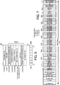
- Fig. 7 depicts an example frame structure in which six bands of signals: three at 25 MHz, two at 45 MHz, and one at 75 MHz are disposed. More or less bands, however, can be used.
- Each of the 25 MHz bands consumes 140 octets in the frame.
- Each of the 45 MHz bands consumes 216 octets in the frame.
- the 75 MHz band consumes 360 octets.
- the total payload consumes 1212 octets.
- a serializer 216 outputs the frame as serial data to communication medium 218 that transports the serial data as shown via the circled B to the remote unit 201 depicted in Fig. 3B .
- the remote unit 201 in Fig. 3B includes a deserializer 220 that converts the serial data to frame data and provides the frame data to de-framer 222.
- a jitter buffer is between the deserializer 220 and the de-framer 222, such as for asynchronous transport.
- the de-framer 222 extracts the re-sampled digital signals according to the defined frame structure and provides each re-sampled digital signals to the appropriate one of the re-sampling devices that are shown as fractional re- sampler M/N 224a-n. These devices can use the reciprocal of the corresponding resample rates to output complex digital signals at 200 MHz.
- Complex mixers 226a-n can remove the complex components of the digital signals and provide digital signals at 14 bits to D/A converters 228a-n.
- the D/A converters can use a sample rate of 200 MHz to convert the digital signals to analog data at an intermediate frequency with which back-end components 230a-n can convert it to an appropriate frequency for amplification by power amplifiers 232a-n and transmission to remote devices.
- the embodiment in Fig. 3B can be implemented without complex mixers 226a-n or with real mixers instead of complex mixers 226a-n.
- Re-sampling devices can be packaged using various configurations.
- the re-sampling devices are modular components that are each packaged separately from other components in a system.
- the re-sampling devices are each packaged in an integrated device with one or more other components, respectively.
- Fig. 8A depicts an integrated device 402 that includes an A/D converter 404, a frequency conversion device that is a complex mixer 406, and a re-sampling device that is a fractional re-sampler N/M 408 in one integrated package.
- the integrated package includes the complex mixer 406 (or other type of frequency conversion device) and the fractional re- sampler N/M 408, but not the A/D converter 404.
- the integrated package may be used with a digital interface for which an A/D converter is not used.
- FIG. 8B depicts a second integrated device 412 that includes a resampling device that is a fractional re-sampler M/N 414, a frequency conversion device that is a complex mixer 416, and a D/A converter 418 in one integrated package.
- the integrated package includes the fractional re-sampler M/N 414 and the complex mixer 416 (or other type of frequency conversion device), but not the D/A converter 418.
Landscapes
- Engineering & Computer Science (AREA)
- Computer Networks & Wireless Communication (AREA)
- Signal Processing (AREA)
- Power Engineering (AREA)
- Analogue/Digital Conversion (AREA)
Abstract
re-sampling circuitry (108a, 108b, 108n, 210a, 210b, 210c, 210n) configured to output re-sampled digital downlink signals by re-sampling digital downlink signals at resample rates (110a, 110b, 110n) based on at least one factor, the re-sampled digital downlink signals having a smaller bandwidth than the digital downlink signals; and
framing circuitry (128, 214) configured to multiplex the re-sampled digital downlink signals and to generate a first frame that includes the re-sampled digital downlink signals as framed data for transport to one or more remotely located communication devices (101, 201) of the communication system, wherein the one or more remotely located communication devices (101, 201) of the communication system are configured to transmit radio frequency signals using at least one antenna, wherein the transmitted radio frequency signals are derived from the framed data of the first frame received from the communication device (100, 200).
Description
- The present invention relates generally to telecommunications and more particularly (although not necessarily exclusively) to efficiently transporting digital RF in a distributed communications system.
- A communications system can include a distributed system capable of transporting signals between carriers and user devices, such as mobile devices. An example of a distributed system is a distributed antenna system that includes one or more master units in communication with carrier systems, such as base transceiver stations of cellular service providers. The distributed antenna system can include remote antenna units physically separated from the master unit, but in communication with the master unit via a serial link that may be copper, optical, or other suitable communication medium. The remote antenna units can also be in wireless communication with user devices. For example, the remote antenna units may be positioned in a building, tunnel, or other structure that prevents or limits communications directly with the carriers.
- The master unit can facilitate communication between the carrier systems and the remote antenna units. For example, the master unit can down- convert and digitize via an analog-to-digital converter (A D) signals received from the carriers and can multiplex the signals into frames that are transmitted over the serial link to the remote antenna units. A signal may be one or more channels having a composite analog or digital waveform with a bandwidth that can be up to the full bandwidth of a designated telecommunication band. Examples of telecommunication bands include US Cellular, SMR800, AWS700, SMR900, EGSM900, DCS1800, PCS 1900, and UMTS2100. The remote antenna units can include a digital-to-analog converter (D/A) to convert the signals to analog signals. The remote antenna units can frequency shift the analog signals to a frequency for transmission to the user devices. Communications from the user device can be similarly processed and transmitted. For example, a remote antenna unit can digitize and package the signals into frames that are transmitted via the serial link to the master unit. The master unit can convert the digital signals to analog signals at a frequency for transmission to the appropriate carrier.
- The master unit can transmit several bands of signals via the serial link to the remote antenna system for distribution to various user devices. The bands of signals can be digitized using a common sample rate. The serial link, however, has a finite amount of bandwidth (e.g. 10 Gbps) available for transferring digitized signals between the master unit and the remote antenna system. Because the bands are sampled at a common sample rate (including those bands having lower bandwidth requirements), serial link bandwidth is underutilized. Accordingly, it is desirable to utilize serial link bandwidth more efficiently.
- One technique to utilize serial link bandwidth more efficiently includes selecting optimal A/D and D/A sample rates for each band to be transported. For example, the master unit can include a plurality of A/Ds. Each A/D is associated with a sample rate provided by a sample clock. The sample rate for an A/D can be selected to accommodate the band of the respective signals being converted by the A/D. The corresponding D/A can use the same sample rate provided by a sample clock at the remote antenna units. The result is that the master unit transports just the required amount of bandwidth for each band at the serial bit rate of the serial link.
- Implementing this technique, however, can be problematic. Generating different sample rates for A/Ds (or for D/As) can be expensive. It can also be difficult to accomplish using hardware. For example, the sample rates must be programmable, requiring low noise frequency synthesizers that can both increase costs and cause performance degradation based on phase noise introduced into the system. Furthermore, this technique requires that the front- end systems that include the A/Ds or D/As be specially manufactured or configured, limiting the ease of manufacturing and replacing these components. In addition, an anti-aliasing filter must be used that is programmable according to the bandwidth to prevent aliasing. Such programmable analog anti-aliasing filters preceding the A/D converter can be difficult to design and configure and can be expensive. Problems may also arise in interfacing with carriers due, for example, to the unavailability of an A/D using an appropriate sample rate for the bandwidth of the analog signals from a particular carrier.
- Therefore, systems and methods are desirable that can utilize serial link bandwidth efficiently without requiring different sample rates for A/Ds or D/As.
- The communication devices of
independent claims - In particular, the instant application shall concern the subject matter as described and claimed in the parent application of the instant application, corresponding to international application
WO 2012/054553 A1 , whose contents shall be incorporated by reference herein. - In particular, according to a first subject matter, a distributed antenna system includes a master unit and a remote unit. The master unit includes an analog-to-digital converter (A/D) and a re-sampling device. The A/D can use a sample rate to convert a downlink RF signal to a digital downlink signal. The re-sampling device can output a re-sampled digital downlink signal by re-sampling the digital downlink signal at a resample rate that is different than the sample rate and that is based on at least one factor. The master unit can provide the re-sampled digital downlink signal to a communication medium. The remote unit includes a second re-sampling device and a digital-to-analog converter (D/A). The second re-sampling device can resample the re-sampled digital downlink signal at a second resample rate that is reciprocal to the resample rate to output the digital downlink signal. The D/A can convert the digital downlink signal to the downlink RF signal.
- According to one aspect of the first subject matter, the remote unit further comprises: a second analog-to-digital converter configured for using a second sample rate to convert an uplink RF signal to a digital uplink signal; and a third re-sampling device configured for outputting a re-sampled digital uplink signal by re-sampling the digital uplink signal at a third resample rate that is different than the second sample rate and that is based on a bandwidth associated with the uplink RF signal, wherein the remote unit is configured for providing the re-sampled digital uplink signal to the communication medium, wherein the master unit is configured to receive the re-sampled digital uplink signal from the communication medium, the master unit further comprising: a fourth re-sampling device configured for re-sampling the resampled digital uplink signal at a fourth resample rate that is reciprocal to the third resample rate to output the digital uplink signal; and a second digital-to-analog converter configured for converting the digital uplink signal to the uplink RF signal.
- According to one aspect of the first subject matter, the communication medium comprises a downlink cable and an uplink cable that is separate from the downlink cable.
- According to one aspect of the first subject matter, the master unit further comprises: a front-end component configured for down-converting the downlink RF signal and filtering the downlink RF signal prior to the analog-to-digital converter converting the downlink RF signal to the digital downlink signal; a complex mixer configured to output the digital downlink signal as a complex digital signal to the re-sampling device; a framer configured for generating a frame comprising the re-sampled digital downlink signal from the re-sampling device; a serializer configured for serializing the frame to generate a serialized frame; and a transmitter configured for providing the serialized frame to the communication medium; wherein the remote unit further comprises: a receiver configured for detecting the serialized frame from the communication medium; a deserializer configured for converting the serialized frame to a parallel frame; a de-framer configured to de-multiplex the parallel frame to extract the re-sampled digital downlink signal and provide the re-sampled digital downlink signal to the second re-sampling device; a second complex mixer configured to remove complex components of the digital downlink signal from the second re-sampling device; and a back-end component configured to convert the downlink RF signal from the digital-to-analog converter to a wireless communications frequency.
- According to one aspect of the first subject matter, the at least one factor comprises at least one of: a bandwidth of the downlink RF signal; the bandwidth owned by a carrier that is a source of the downlink RF signal; the bandwidth of the communication medium; or a capability of at least one component in communication with the distributed antenna system.
- According to another, second subject matter, a wireless telecommunications signal distribution system is provided that includes A/Ds and re-sampling devices. The A/Ds can convert signals using a common sample rate to digital signals corresponding to the signals. The re-sampling devices can output re-sampled signals. Each re-sampling device can resample a digital signal at a resample rate that is different than the common sample rate and that is based on a bandwidth associated with at least one of a component of the system, an input signal, or a carrier in communication with the system.
- According to one aspect of the second subject matter, the component comprises a communication medium between a first device and a second device, wherein the first device is a master unit, wherein the second device is a remote unit in which the analog-to-digital converters and the re-sampling devices are disposed.
- According to one aspect of the second subject matter, the component comprises a communication medium between a first device and a second device, wherein the first device is a master unit in which the analog-to-digital converters and the re-sampling devices are disposed, wherein the second device is a remote unit.
- In one embodiment of the aforementioned aspect, the remote unit is configured to receive the re-sampled signals from the communication medium, the remote unit comprising: second re-sampling devices configured for outputting the plurality of digital signals from the re-sampled signals, each second re-sampling device being configured for re-sampling a re-sampled signal at a rate that is reciprocal to the resample rate of the re-sampled signal; digital-to-analog converters configured for converting the plurality of digital signals to a plurality of RF signals.
- In one further development of the aforementioned embodiment, the master unit further comprises: front-end components configured for down-converting the plurality of signals and filtering the plurality of signals prior to the analog-to-digital converters converting the plurality of signals to the plurality of digital signals corresponding to the plurality of signals; complex mixers configured to output the plurality of digital signals as a plurality of complex digital signals to the re-sampling devices; a framer configured for generating a frame comprising the re-sampled signals; a serializer configured for serializing the frame to generate a serialized frame; and a transmitter configured for providing the serialized frame to the communication medium, wherein the remote unit further comprises: a receiver configured for detecting the serialized frame from the communication medium; a deserializer configured for converting the serialized frame to a parallel frame; a de-framer configured to de-multiplex the parallel frame to extract the re-sampled signals and provide the re-sampled signals to the second resampling devices; second complex mixers configured to remove complex components of the plurality of digital signals from the second re-sampling devices; and back-end components configured to convert the plurality of RF signals to wireless communications frequencies.
- In one variant of the aforementioned further development, (i) at least one of the re-sampling devices, (ii) a complex mixer, and (iii) an analog-to-digital converter, are disposed in an integrated package that is in the master unit, wherein (i) at least one of the second re-sampling devices, (ii) a second complex mixer, and (iii) a digital-to-analog converter are disposed in a second integrated package.
- According to one aspect of the second subject matter, the resample rate is based on the bandwidth of the input signal corresponding to the digital signal being re-sampled.
- According to one aspect of the second subject matter, the bandwidth associated with the carrier in communication with the wireless telecommunications signal distribution system comprises the bandwidth owned by the carrier that is a source of at least one signal of the plurality of signals.
- According to yet another, third subject matter, a system is provided that includes an interface device and a re-sampling device. The interface device can provide a previously sampled digital signal to the re-sampling device. The re-sampling device can output a re-sampled digital signal by re-sampling the previously sampled digital signal using a resample rate that is based on a bandwidth associated with at least one of a component of the system, a signal represented by the previously sampled digital signal, or a carrier in communication with the system.
- According to one aspect of the third subject matter, the system further comprises a framer configured for generating a frame comprising the re-sampled digital signal; and a transmitter configured for outputting the frame to a communication medium.
- According to one embodiment of the aforementioned aspect, the system further comprises a second device comprising: a receiver configured for detecting the frame from the communication medium; a de-framer configured for extracting the re-sampled digital signal from the frame; a second re-sampling device configured for outputting the digital signal by re-sampling the re-sampled digital signal at a rate that is related to the resample rate.
- According to one variant of the aforementioned embodiment, the second device comprises: a digital-to-analog converter configured to convert the digital signal to the RF signal, wherein the system further comprises an analog-to-digital converter configured to convert an RF signal to the previously sampled digital signal.
- According to one further development of the aforementioned variant, the second device further comprises: a frequency conversion device configured for processing the digital signal from the second re-sampling device and providing the digital signal to the digital-to-analog converter, wherein the second re-sampling device and the frequency conversion device, and the digital-to-analog converter are disposed in an integrated package.
- According to another further development of the aforementioned variant, the second device is a remote unit of a distributed antenna system, wherein the analog-to-digital converter, the re-sampling device, the framer, and the transmitter are disposed in a master unit of the distributed antenna system.
- According to yet another further development of the aforementioned variant, the system further comprises a frequency conversion device configured for processing the previously sampled digital signal from the analog-to-digital converter to generate a complex digital signal, wherein the re-sampling device is configured for re-sampling the digital signal by re-sampling the complex digital signal.
- According to another variant of the aforementioned embodiment, the rate that is related to the resample rate is reciprocal to the resample rate.
- According to one aspect of the third subject matter, the system further comprises a band filter for filtering the resampled digital signal from the re-sampling device, wherein a band filter bandwidth is based at least in part on the bandwidth of the RF signal.
- According to one aspect of the third subject matter, the interface device is a digital interface device configured for receiving the previously sampled digital signal from a carrier.
- The terms "invention," "the invention," "this invention" and "the present invention" used in this patent are intended to refer broadly to all of the subject matter of this patent and the patent claims below. Statements containing these terms should be understood not to limit the subject matter described herein or to limit the meaning or scope of the patent claims below. Features of the invention covered by this patent are defined by the claims below, not this summary. This summary is a high-level overview of various aspects of the invention and introduces some of the concepts that are further described in the Detailed Description section below. This summary is not intended to identify key or essential features of the claimed subject matter, nor is it intended to be used in isolation to determine the scope of the claimed subject matter. The subject matter should be understood by reference to appropriate portions of the entire specification of this patent, any or all drawings and each claim.
-
-
Fig. 1 is a block diagram of a communication system having resampling devices according to one embodiment of the present invention. -
Fig. 2A is a block diagram of a master unit capable of communicating data from input signals via a serial link according to one embodiment of the present invention. -
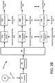
Fig. 2B is a block diagram of a remote unit capable of receiving digital signals representing the input signals from the master unit ofFig. 2A via the serial link according to one embodiment of the present invention. -
Fig. 3A is a block diagram of a master unit with re-sampling devices according to a second embodiment of the present invention. -
Fig. 3B is a block diagram of a remote unit having re-sampling devices and being capable of communicating with the master unit ofFig. 3A according to a second embodiment of the present invention. -
Fig. 4 includes a table of resample rate examples according to one embodiment of the present invention. -
Fig. 5 depicts a frame structure according to one embodiment of the present invention. -
Fig. 6 includes a table of frame structure fields and corresponding octets according to one embodiment of the present invention. -
Fig. 7 depicts a frame structure having payload that includes signals from six bands according to one embodiment of the present invention. -
Fig. 8A is a block diagram of an integrated device having an analog-to-digital converter (A D), mixer, and re-sampling device disposed therein according to one embodiment of the present invention. -
Fig. 8B is a block diagram of an integrated device having a resampling device, a mixer, and a digital-to-analog converter (D/A) disposed therein according to one embodiment of the present invention. - Certain aspects and features relate to re-sampling a digitized signal at a resample rate that is selected based on one or more factors - a "flex- banding" approach. The factors can include the bandwidth of the input signal that the digitized signal represents, the amount of bandwidth owned or used by the carrier that is the source of the input signal, the full bandwidth of the designated RF band, the bandwidth of the serial link, the frame length of the serial link, the segmentation of the frames on the serial link, and the capability of the equipment at the receiving end of a serial link. The re-sampled signal can be multiplexed and transmitted on the serial link to another unit that is remote to the unit transmitting the signal. The other unit can include a re-sampling device capable of restoring the re-sampled signal to a digital signal that can be converted to an analog signal by a digital-to-analog converter (D/A). By resampling the digitized signal at the selected resample rate, the bandwidth of the serial link can be better utilized without requiring an analog-to-digital converter (A D) or a D/A to be specially configured. For example, certain embodiments can allow digitized signals to be transported at or as close as possible to a minimal sampling rate needed for the relevant RF band(s).
- In some embodiments, a master unit is provided that is in communication with various telecommunication network operators which are referred to herein as carriers, such as cellular service providers. The master unit can process composite input signals from the various carriers by converting the input signals to digital signals using a common sample rate and re-sampling each digital signal at a resample rate that is selected based on one or more factors, such as the bandwidth of the particular input signal that the digital signal represents. In other embodiments, the master unit can receive previously sampled signals as digital signals from one or more carriers and re-sample the previously sampled signals at the resample rate. The re-sampled signals can be transmitted to a remote unit that can process the re-sampled signals to generate analog signals corresponding to the input signals. The analog signals can be transmitted wirelessly (or otherwise) to remote devices, such as mobile devices. This can be referred to as a "downlink path." An "uplink path" can include similar processing of signals from the remote devices for receipt by a respective carrier, except the remote units include circuitry or modules capable of re-sampling a digital representation of each signal at a selected resample rate for each signal and the master unit is capable of processing the re-sampled signals to generate analog signals corresponding to the signals from the remote devices, or to generate digital signals corresponding to the signals from the remote devices.
- A "re-sampling device" may be a device that receives a digital signal that is sampled at a certain sample rate and outputs a digital signal that is sampled at a different sample rate. A sample rate can be changed using any rational relationship between an input sample rate and an output sample rate, as shown by the following relationship: Fout = Fin * l/D. "I" and "D" can be any integer, including one. When "D" is one, a re-sampling device may effectively be an interpolator. When "I" is one, a re-sampling device may effectively be a decimator.
- Decimation can be performed by first filtering the digital signal to prevent aliasing when the lower sample rate is applied. The filter parameters can be selected to prevent aliasing that may result from the down-sampling operation. Aliasing may not be completely prevented, but the filter stop-band can be selected such that acceptably low level of aliasing occurs due to down- sampling the signal. In some implementations, the filter is selected to have a stop-band that starts at a frequency of ωstop = π/D radians/second.
- An interpolator can first insert 1-1 zeroes between incoming samples. As a result, images of the original spectrum can occur every 2 π/I radians/second. In some implementations, the filter that follows the up-sampling has a ωstop = π/l radians/second.
- In some implementations, fractional rate changes of l/D can be performed. In these implementations, the process of interpolation and decimation can be combined to produce a rate change that is Fin * l/D. The interpolation filter and the decimation filter can be combined to form a single filter. The stop-band of the filter can be selected to be ωstop = min{π /D, π/l} radians/second.
- These illustrative examples are given to introduce the reader to the general subject matter discussed here and are not intended to limit the scope of the disclosed concepts. The following sections describe various additional embodiments and examples with reference to the drawings in which like numerals indicate like elements, and directional descriptions are used to describe the illustrative embodiments but, like the illustrative embodiments, should not be used to limit the present invention.
-
Fig. 1 depicts a downlink path from amaster unit 100 to aremote unit 101 according to one embodiment. Aninput signal 102, such as a signal from a carrier, is received. Theinput signal 102 can be associated with a bandwidth that may depend on the bandwidth that the carrier owns or has configured the carrier system to utilize. Themaster unit 100 includes an analog interface, such as ananti-aliasing filter 103 that is capable of filtering theinput signal 102 and an A/D converter 104 that is capable of converting theinput signal 102 to a digital signal by sampling theinput signal 102 at asample rate 106. In some embodiments, as explained below, the interface device also includes an RF front-end. Thesample rate 106 can be a common sample rate that is used to convert signals from carriers generally. In other embodiments, the interface device is a digital interface that is configured to receive a previously sampled signal as a digital input signal. For example, the digital interface may replace theanti-aliasing filter 103 and A/D converter 104 inFig. 1 . - The digital signal is re-sampled by a
re-sampling device 108 at aresample rate 110 that is selected based on one or more factors that can include the bandwidth associated with theinput signal 102 and / or the bandwidth that the carrier owns. Other factors include the bandwidth of acommunication medium 114 between themaster unit 100 and remote unit, and the capability of theremote unit 101. For example, theresample rate 110 may be different if thecommunication medium 114 has a 10 Gbps bandwidth as opposed to one with a bandwidth of 1 Gbps. Theresample rate 110 can be generated and configured using hardware, software, or a combination of hardware and software. For example, themaster unit 100 can include an application-specific integrated circuit (ASIC), a field-programmable gate array (FPGA), a digital signal processor (DSP), or similar device that is capable of outputting and / or generating theresample rate 110 based on the one or more factors. In some embodiments, theresample rate 110 is configured manually or remotely based on the bandwidth of theinput signal 102 at location of themaster unit 100. In other embodiments, theresample rate 110 is selected dynamically or automatically based on the one or more factors. Theresample rate 110 may be lower than thesample rate 106 such that the bandwidth of the re-sampled signal is less than the digital signal. The re-sampled signal can be transmitted by atransmitter 112 over thecommunication medium 114 to theremote unit 101 . Thecommunication medium 114 may be any medium capable of carrying the re-sample signal to theremote unit 101. In some embodiments, thecommunication medium 114 is a serial link. Examples ofcommunication medium 114 include a copper or optical cable and a microwave link. Thecommunication medium 114 may include a downlink cable and an uplink cable that is separate from the downlink cable. - The
remote unit 101 can include areceiver 116 that can detect the re-sampled signal from thecommunication medium 114. Thereceiver 116 can provide the re-sampled signal to are-sampling device 118 that can use a rate that is related to theresample rate 120, such as a reciprocal of theresample rate 120 to output a digital signal that corresponds to the digital signal outputted by the A/D converter 104. In some embodiments, the reciprocal of theresample rate 120 is the inverse of theresample rate 110. In other embodiments, the reciprocal of theresample rate 120 is not the inverse of theresample rate 110 and instead is a rate that has a relationship to theresample rate 120. Theremote unit 101 can include a D/A converter 122 that can use asample rate 124 to convert the digital signal to anoutput signal 126 that corresponds to, or represents, theinput signal 102. Theoutput signal 126 can be transmitted to a remote device, such as a mobile device, by theremote unit 101. For example, theremote unit 101 may be a remote antenna unit that is capable of wirelessly communicating with a mobile device. In some embodiments, theremote unit 101 includes an analog interpolating filter and an RF back-end that are capable of processing the analog signal prior to transmission. - Although only a downlink path is depicted in
Fig. 1 , various embodiments contemplate a bidirectional communication system, such as a system that also includes an uplink path. For example, theremote unit 101 can receive signals from remote devices, convert them to a digital representation, re- sample the signals and transmit re-sampled signals viacommunication medium 114, or a second communication medium, to themaster unit 100 and themaster unit 100 can process the re-sampled signals to output corresponding signals, analog or digital, to the carrier. - The
master unit 100 can include additional components capable of receiving more than one input signal from one or more carriers and transmitting a digital representation of the input signals to theremote unit 101 for distribution to various remote devices. In some embodiments, themaster unit 100 is configured to resample one digital signal corresponding to one input signal and transmit the re-sampled digital signal with digital signals corresponding to other input signals. Theremote unit 101 can include components capable of processing the re-sampled digital signal and the digital signals. Re-sampling one digital signal, for example, can decrease the amount of bandwidth required to transmit the re-sampled digital signal with the other digital signals that are not re- sampled. In other embodiments, themaster unit 100 includes components capable of re-sampling digital signals representing various input signals such that the required bandwidth is decreased even more. Theremote unit 101 can include components capable of processing the re-sampled digital signals. -
Fig. 2A depicts an example of themaster unit 100 that includes additional components for re-sampling digital signals representing input signals 102a-n from various sources or carriers. The input signals 102a-n may be associated with different bandwidths, such as the bandwidths of the input signals 102a-n and / or the bandwidths owned by the carriers. Themaster unit 100 can transmit the re-sampled digital signals to theremote unit 101 that is depicted inFig. 2B . - The
master unit 100 includesanti-aliasing filters 103a-n that are capable of filtering input signals 102a-n. Themaster unit 100 also includes A/D converters 104a-n, each being capable of converting an input signal to a digital signal at acommon sample rate 106. For example, A/D converter 104a convertsinput signal 102a to a digital signal and A/D converter 104b convertsinput signal 102b to a second digital signal. In other embodiments, one or more of bothantialiasing filters 103a-n and A/D converters 104-a-n are replaced with a digital interface that can receive a previously sampled signal as an input digital signal. Themaster unit 100 includesre-sampling devices 108a-n, each being capable of re-sampling a digital signal at aresample rate 110a-n that is selected based on one or more factors, such as the bandwidth of the input signal that the particular digital signal represents. For example,re-sampling device 108a is capable of resampling the digital signal from A/D converter 104a at aresample rate 110a that can depend on the bandwidth of theinput signal 102a.Re-sampling device 108b can resample the digital signal fromAID converter 104b at aresample rate 110b that can depend on the bandwidth of theinput signal 102b and that may be different than theresample rate 110a. The output of there-sampling devices 108a-n includes re-sampled signals that may have been re-sampled at different resample rates and, thus, can have different bandwidths. - The
master unit 100 can include aframer 128 that, as explained in more detail below, can multiplex the re-sampled digital signals and create a frame that includes the re-sampled signals from one or more of there-sampling devices 108a-n disposed in the frame. The framed data can be serialized by theserializer 130 and provided to thetransmitter 112 for output on thecommunication medium 114 to theremote unit 101, as shown by the circled A inFigs. 2A-B . For example, thecommunication medium 114 may be an optical fiber (single mode or multimode) and thetransmitter 112 can be capable of translating the serialized data into a coded light pulses that form a serial bit stream and of using an injection-laser diode, or other suitable light source, to generate light pulses that are, using suitable optical lenses, provided to the optical fiber. By re-sampling the digital signals at flexible re-sampling rates, the bandwidth of thecommunication medium 114 can be better utilized. - The
remote unit 101 includes areceiver 116 that can detect the serialized data fromcommunication medium 114. For example, thereceiver 116 can include a light sensitive component capable of detecting the light pulses from acommunication medium 114 that is an optical fiber, and can include a translation component capable of translating the light pulses to serial frame data represented digitally. The serial frame data can be provided to adeserializer 132. Thedeserializer 132 can convert the serial frame data to parallel frame data that is provided tode-framer 134. The de-framer 134 can de-multiplex the parallel frame data and extract each of the re-sampled digital signals. In some embodiments, a jitter buffer is positioned between thedeserializer 132 and de-framer 134, such as wherecommunication medium 114 allows for asynchronous serial transport. - The re-sampled digital signals can be provided to
re-sampling devices 118a-n such that a re-sampled digital signal is provided to the appropriate re-sampling device. Each of there-sampling devices 118a-n can use corresponding reciprocals of theresample rates 120a-n, or otherwise rates related to theresample rates 120a-n, to convert the re-sampled digital signals to digital signals, such as complex digital signals at baseband. For example,resampling device 1 18a can use a reciprocal of theresample rate 120a that is the reciprocal ofresample rate 110a to convert a re-sampled digital signal to a real or complex digital signal at baseband that representsinput signal 102a. Similarly, reciprocal of theresample rate 120b can correspond to resamplerate 110b and can be used to output a real or complex digital signal at baseband that representsinput signal 102b. - The digital signals can be provided to D/
A converters 122a-n such that a digital signal is provided to the appropriate D/A converter. The D/A converters 122a-n convert the digital signals usingsample rate 124 and up- convert the signals to an appropriate frequency for modulation ontoanalog output signals 126a-n. In some embodiments, thesample rate 124 is the same rate assample rate 106. In other embodiments, thesample rate 124 is different than thesample rate 106. -
Figs. 3A-3B schematically depict a second embodiment for implementing amaster unit 200 communicating with aremote unit 201 via acommunication medium 218. As with the embodiments disclosed inFigs. 1 and2A-2B , a downlink path is shown and described, but various aspects can be applied to an uplink path from aremote unit 201 to amaster unit 200 alternatively or in addition to the downlink path described. - The
master unit 200 includes front-end components 202a-n, each capable of receiving an input signal from a carrier and down-converting the input signal from a radio frequency (RF) to an intermediate frequency (IF). The front-end components 202a-n can each include a low noise amplifier, mixer, and antialiasing filters to down-convert the input signal to the IF frequency and to prevent aliasing. The front-end components 202a-n may be configured to be generic such that the front-end components 202a-n are usable for different bands (e.g. AMPS, PCS, and AWS). Each input signal corresponds to a bandwidth and / or a bandwidth owned by the respective carrier. The input signals at IF can be converted to digital signals by A/D converters 204a-n. The A/D converters 204a- n shown inFig. 3A use a sample rate of 200 MHz. Other sample rates can be used. The sample rate may be selected so that the same hardware can be used for any band. The output of the A/D converters 204a-n inFig. 3A includes 14-bit digital signals at 200 MHz that are provided to first in, first out (FIFO)devices 206a-n. In some embodiments, the output of the A/D converters 204a-n are complex signals. TheFIFO devices 206a-n can assist in ensuring proper timing in the system or otherwise queuing digital signals for further processing. The digital signals are provided tocomplex mixers 208a-n that are capable of outputting complex digital signals (e.g. signals representing both in-phase and quadrature components) that are at baseband. The embodiment shown inFig. 3A can be implemented withoutcomplex mixers 208a-n, or with real mixers instead of complex mixers. In some embodiments, themaster unit 200 can include a digital interface that receives previously sampled signals as input digital signals. - The complex digital signals are provided to re-sampling devices that are fractional re-samplers 210a-n. Each of the fractional re-samplers 210a-n is capable of re-sampling a complex digital signal according to a resample rate (N/M) that is selected based on factors such as the bandwidth of the corresponding input signal. The output of the fractional re-samplers 210a-n includes re-sampled complex digital signals.
Figure 4 includes a table that depicts examples of re-sample rates for N values of 1 to 15 for various carrier or input signal bandwidths. An example of M is 30. - As shown in the examples in the table of
Fig. 4 , the resample rate can be selected based on the carrier bandwidth such that lower resample rates can be used for lower bandwidths and such that the re-sampling rate is greater than or equal to the occupied bandwidth of the carrier signals, including a filter shape factor. The number of complex samples can be determined by dividing a frame period of a communication medium, (e.g. a serial link having a frame period of 1.2 µs, by a complex re-sampled sample period (1/resample rate). The number of octets per sample can be determined by dividing the number of bits required by eight. The number of octets of data to be included in a frame is an integer number that depends on the resample rate and the number of octets per sample such that lower carrier bandwidth signals consume fewer octets for a frame. The number of octets can be determined by multiplying the number of complex samples by the number of octets per sample and by two. Multiplying by two can account for complex signals that include an I and Q term for each sample. In some embodiments, and as reflected in the table inFig. 4 , lower values of N correspond to more required bits to account for narrower re-sampling that filters more noise. The additional bits (in this example two additional bits, although one additional bit can be sufficient for some bandwidths) are included to represent the signal so that the noise voltage traverses enough quantization levels to stay in the linear region of A/D converters when no signal is present. For example, if too much noise (e.g. a percentage greater than a certain threshold) is filtered out of the signal and no signal is present, the noise may not traverse more than one quantization level and the system is muted. The additional bit or bits can prevent such muting. In some implementations, when the noise is reduced by a factor of one-fourth, another bit is added. For example, reducing from 80MHz to 20 MHz may involve adding a bit and reducing from 20MHz to 5MHz may involve adding a bit. Each bit can represent a 6dB increase in dynamic range. - The re-sampled signals are provided to
band filters 212a-n inFig. 3A for filtering to ensure a desired band is passed. For example, a band filter can be configured to pass signals from one carrier (the carrier providing the input signals for which the band filter is processing the corresponding digital signals), but not from another carrier. The band filters 212a-n may also increase downlink to uplink isolation. The bandwidth of each of the band filters 212a-n may depend on the bandwidth of the respective input signals. For example, the bandwidth ofband filter 212a can depend on the bandwidth of theinput signal 1 and the bandwidth ofband filter 212b can depend on the bandwidth of theinput signal 2. Theframer 214 can multiplex the re-sampled and filtered digital signals and generate a frame having the re-sampled and filtered digital signals disposed therein. -
Fig. 5 depicts an example of a frame structure that framer 214 can be configured to use. The frame structure inFig. 5 is an Ethernet frame structure usable in a system implementing the IEEE 802.3 standard. Other types of frame structures, such as SONET, CPRI, and OBSAI, however, can be used. The Ethernet frame structure uses a frame length of 1500 octets, but other lengths can be used. The Ethernet frame structure includes apacket 302 that includes apreamble 304 corresponding to seven octets, a start frame delimiter (SFD) 306 corresponding to one octet, a frame, and anextension 320. - The frame includes a
destination address 308 corresponding to six octets, asource address 310 corresponding to six octets, length/type corresponding to two octets,MAC client data 314, packet assembler/disassembler (PAD) 316, and aframe check sequence 318 corresponding to four octets. TheMAC client data 314 andPAD 316 can correspond to 46 to 1500 or 1504, or 1982 octets, depending on the payload size and frame length. - The octets in the fields can be transmitted in order from top to bottom in the frame structure depicted in
Fig. 5. Fig. 5 also depicts abit structure 322 for the fields from which bits are transmitted from left to right (i.e. from the length significant bit (LSB) to the most significant bit (MSB)). - A table in
Fig. 6 lists the fields of the frame structure and corresponding octets, including the available octets for payload data. In this example, the number of octets available for payload data is 1297 octets if the link in an installation includes a 1 Gb link and control data. If not included, the number of octets available for payload data is 1447. An example of a frame rate for the data in the table ofFig. 6 is 833333.333 Hz and an example frame duration is 1 .2 µε. -
Fig. 7 depicts an example frame structure in which six bands of signals: three at 25 MHz, two at 45 MHz, and one at 75 MHz are disposed. More or less bands, however, can be used. Each of the 25 MHz bands consumes 140 octets in the frame. Each of the 45 MHz bands consumes 216 octets in the frame. The 75 MHz band consumes 360 octets. The total payload consumes 1212 octets. By re-sampling the digital signals using customized resample rates, the number of octets consumed by six bands, for example, is reduced. - Returning to
Fig. 3A , aserializer 216 outputs the frame as serial data tocommunication medium 218 that transports the serial data as shown via the circled B to theremote unit 201 depicted inFig. 3B . Theremote unit 201 inFig. 3B includes adeserializer 220 that converts the serial data to frame data and provides the frame data to de-framer 222. In some embodiments, a jitter buffer is between thedeserializer 220 and the de-framer 222, such as for asynchronous transport. The de-framer 222 extracts the re-sampled digital signals according to the defined frame structure and provides each re-sampled digital signals to the appropriate one of the re-sampling devices that are shown as fractional re- sampler M/N 224a-n. These devices can use the reciprocal of the corresponding resample rates to output complex digital signals at 200 MHz.Complex mixers 226a-n can remove the complex components of the digital signals and provide digital signals at 14 bits to D/A converters 228a-n. The D/A converters can use a sample rate of 200 MHz to convert the digital signals to analog data at an intermediate frequency with which back-end components 230a-n can convert it to an appropriate frequency for amplification bypower amplifiers 232a-n and transmission to remote devices. The embodiment inFig. 3B can be implemented withoutcomplex mixers 226a-n or with real mixers instead ofcomplex mixers 226a-n. - Re-sampling devices according to various embodiments of the present invention can be packaged using various configurations. In some embodiments, the re-sampling devices are modular components that are each packaged separately from other components in a system. In other embodiments, the re-sampling devices are each packaged in an integrated device with one or more other components, respectively.
-
Fig. 8A depicts anintegrated device 402 that includes an A/D converter 404, a frequency conversion device that is acomplex mixer 406, and a re-sampling device that is a fractional re-sampler N/M 408 in one integrated package. In other embodiments, the integrated package includes the complex mixer 406 (or other type of frequency conversion device) and the fractional re- sampler N/M 408, but not the A/D converter 404. For example, the integrated package may be used with a digital interface for which an A/D converter is not used.Fig. 8B depicts a secondintegrated device 412 that includes a resampling device that is a fractional re-sampler M/N 414, a frequency conversion device that is acomplex mixer 416, and a D/A converter 418 in one integrated package. In other embodiments, the integrated package includes the fractional re-sampler M/N 414 and the complex mixer 416 (or other type of frequency conversion device), but not the D/A converter 418. - The foregoing description of the embodiments, including illustrated embodiments, of the invention has been presented only for the purpose of illustration and description and is not intended to be exhaustive or to limit the invention to the precise forms disclosed. Numerous modifications, adaptations, and uses thereof will be apparent to those skilled in the art without departing from the scope of this invention.
Claims (15)
- A communication device (100, 200) for use within a communication system, the device comprising:re-sampling circuitry (108a, 108b, 108n, 210a, 210b, 210c, 210n) configured to output re-sampled digital downlink signals by re-sampling digital downlink signals at resample rates (110a, 110b, 110n) based on at least one factor, the re-sampled digital downlink signals having a smaller bandwidth than the digital downlink signals; andframing circuitry (128, 214) configured to multiplex the re-sampled digital downlink signals and to generate a first frame that includes the re-sampled digital downlink signals as framed data for transport to one or more remotely located communication devices (101, 201) of the communication system, wherein the one or more remotely located communication devices (101, 201) of the communication system are configured to transmit radio frequency signals using at least one antenna, wherein the transmitted radio frequency signals are derived from the framed data of the first frame received from the communication device (100, 200).
- The communication device (100, 200) of claim 1, wherein the digital downlink signals are received from one or more telecommunication network operators.
- The communication device (100, 200) of one of the preceding claims, wherein the first frame contains more information as compared to a second frame containing the digital downlink signals, wherein the second frame is a same size as the first frame.
- The communication device (100, 200) of one of the preceding claims, wherein the resample rates include a first resample rate and a second resample rate that is at a different rate than the first resample rate.
- The communication device (100, 200) of one of the preceding claims, wherein the first frame is an Ethernet frame comprising a preamble, a start frame delimiter, a destination address, a source address, length or type, MAC client data, packet assembler/dissembler, a frame check sequence, and an extension.
- The communication device (100, 200) of one of the preceding claims, wherein the at least one factor includes a bandwidth owned by a telecommunication network operator that is a source of the downlink radio frequency signals.
- The communication device (100, 200) of one of the preceding claims, wherein the at least one factor includes the bandwidth of a communication medium between the communication device (100, 200) and the one or more remotely located communication devices (101, 201).
- The communication device (100, 200) of one of the preceding claims, wherein the at least one factor includes the bandwidth of the downlink radio frequency signals.
- A communication device (100, 200) for use within a communication system, the communication device (100, 200) comprising:de-framing circuitry configured to extract re-sampled digital uplink signals from a first frame that includes the re-sampled digital uplink signals as framed data received from one or more remotely located communication devices (101, 201) of the communication system, wherein the one or more remotely located communication devices (101, 201) of the communication system are configured to receive radio frequency signals using at least one antenna, to generate the framed data of the first frame based on the radio frequency signals, and to transmit the first frame to the communication device (100, 200);re-sampling circuitry configured to output digital uplink signals by re-sampling the re-sampled digital uplink signals from resample rates to a sample rate based on at least one factor, the re-sampled digital uplink signals having a smaller bandwidth than the digital uplink signals.
- The communication device (100, 200) of claim 9, wherein the digital uplink signals are transmitted to one or more telecommunication network operators.
- The communication device (100, 200) of claim 9 or claim 10, wherein the first frame contains more information as compared to a second frame containing the digital uplink signals and that is a same size as the first frame.
- The communication device (100, 200) of one of claims 9 to 11, wherein the resample rates include a first resample rate and a second resample rate that is at a different rate than the first resample rate.
- The communication device (100, 200) of one of claims 9 to 12, wherein the first frame is an Ethernet frame comprising a preamble, a start frame delimiter, a destination address, a source address, length or type, MAC client data, packet assembler/dissembler, a frame check sequence, and an extension.
- The communication device (100, 200) of one of claims 9 to 13, wherein the at least one factor includes at least one of:the bandwidth of a communication medium between the communication device (100, 200) and the one or more remotely located communication devices (101, 201); orthe bandwidth of the uplink radio frequency signals.
- A communication device (100, 200) for use within a communication system, the communication device (100, 200) comprising:analog-to-digital converting circuitry configured to use a sample rate to convert uplink radio frequency signals to digital uplink signals;re-sampling circuitry (108a, 108b, 108n, 210a, 210b, 210c, 210n) configured to output re-sampled digital uplink signals by re-sampling the digital uplink signals at resample rates (110a, 110b, 110n) based on at least one factor, wherein the resample rates are less than the sample rate, and wherein the re-sampled digital uplink signals have a smaller bandwidth than the digital uplink signals; andframing circuitry (128, 214) configured to multiplex the re-sampled digital uplink signals and to generate a first frame that includes the re-sampled digital uplink signals as framed data for transport to a remotely located communication device (101, 201) of the communication system, wherein the remotely located communication device (101, 201) of the communication system is configured to communicate uplink signals derived from the framed data of the first frame received from the communication device (100, 200).
Applications Claiming Priority (3)
| Application Number | Priority Date | Filing Date | Title |
|---|---|---|---|
| US39446210P | 2010-10-19 | 2010-10-19 | |
| PCT/US2011/056809 WO2012054553A1 (en) | 2010-10-19 | 2011-10-19 | Systems and methods for transporting digital rf signals |
| EP11776295.5A EP2630759B1 (en) | 2010-10-19 | 2011-10-19 | Systems and methods for transporting digital rf signals |
Related Parent Applications (1)
| Application Number | Title | Priority Date | Filing Date |
|---|---|---|---|
| EP11776295.5A Division EP2630759B1 (en) | 2010-10-19 | 2011-10-19 | Systems and methods for transporting digital rf signals |
Publications (2)
| Publication Number | Publication Date |
|---|---|
| EP3522467A1 true EP3522467A1 (en) | 2019-08-07 |
| EP3522467B1 EP3522467B1 (en) | 2024-07-03 |
Family
ID=44883426
Family Applications (2)
| Application Number | Title | Priority Date | Filing Date |
|---|---|---|---|
| EP11776295.5A Active EP2630759B1 (en) | 2010-10-19 | 2011-10-19 | Systems and methods for transporting digital rf signals |
| EP19163724.8A Active EP3522467B1 (en) | 2010-10-19 | 2011-10-19 | Systems and methods for transporting digital rf signals |
Family Applications Before (1)
| Application Number | Title | Priority Date | Filing Date |
|---|---|---|---|
| EP11776295.5A Active EP2630759B1 (en) | 2010-10-19 | 2011-10-19 | Systems and methods for transporting digital rf signals |
Country Status (3)
| Country | Link |
|---|---|
| US (5) | US9130609B2 (en) |
| EP (2) | EP2630759B1 (en) |
| WO (1) | WO2012054553A1 (en) |
Families Citing this family (47)
| Publication number | Priority date | Publication date | Assignee | Title |
|---|---|---|---|---|
| US8594133B2 (en) | 2007-10-22 | 2013-11-26 | Corning Mobileaccess Ltd. | Communication system using low bandwidth wires |
| AU2010210766A1 (en) | 2009-02-03 | 2011-09-15 | Corning Cable Systems Llc | Optical fiber-based distributed antenna systems, components, and related methods for monitoring and configuring thereof |
| US8280259B2 (en) | 2009-11-13 | 2012-10-02 | Corning Cable Systems Llc | Radio-over-fiber (RoF) system for protocol-independent wired and/or wireless communication |
| US8275265B2 (en) | 2010-02-15 | 2012-09-25 | Corning Cable Systems Llc | Dynamic cell bonding (DCB) for radio-over-fiber (RoF)-based networks and communication systems and related methods |
| US9525488B2 (en) | 2010-05-02 | 2016-12-20 | Corning Optical Communications LLC | Digital data services and/or power distribution in optical fiber-based distributed communications systems providing digital data and radio frequency (RF) communications services, and related components and methods |
| EP2606707A1 (en) | 2010-08-16 | 2013-06-26 | Corning Cable Systems LLC | Remote antenna clusters and related systems, components, and methods supporting digital data signal propagation between remote antenna units |
| CN103229427B (en) * | 2010-10-01 | 2016-08-03 | 康普技术有限责任公司 | Distributing antenna system for MIMO signal |
| US9252874B2 (en) | 2010-10-13 | 2016-02-02 | Ccs Technology, Inc | Power management for remote antenna units in distributed antenna systems |
| EP2630759B1 (en) | 2010-10-19 | 2019-03-20 | CommScope Technologies LLC | Systems and methods for transporting digital rf signals |
| CN203504582U (en) | 2011-02-21 | 2014-03-26 | 康宁光缆系统有限责任公司 | Distributed antenna system and power supply device for distributing power therein |
| CN103609146B (en) | 2011-04-29 | 2017-05-31 | 康宁光缆系统有限责任公司 | Systems, methods and apparatus for increasing radio frequency (RF) power in a distributed antenna system |
| US9060382B2 (en) * | 2011-10-13 | 2015-06-16 | Broadcom Corporation | Split architecture remote radio |
| EP3422589B1 (en) | 2012-02-02 | 2024-07-24 | CommScope Technologies LLC | Optimized telecommunications distribution system |
| WO2013142662A2 (en) | 2012-03-23 | 2013-09-26 | Corning Mobile Access Ltd. | Radio-frequency integrated circuit (rfic) chip(s) for providing distributed antenna system functionalities, and related components, systems, and methods |
| EP2832012A1 (en) | 2012-03-30 | 2015-02-04 | Corning Optical Communications LLC | Reducing location-dependent interference in distributed antenna systems operating in multiple-input, multiple-output (mimo) configuration, and related components, systems, and methods |
| EP2789107B1 (en) | 2012-08-09 | 2017-02-15 | Axell Wireless Ltd. | A digital capacity centric distributed antenna system |
| US9455784B2 (en) | 2012-10-31 | 2016-09-27 | Corning Optical Communications Wireless Ltd | Deployable wireless infrastructures and methods of deploying wireless infrastructures |
| CN104782093B (en) | 2012-10-31 | 2018-02-27 | 康普技术有限责任公司 | Digital Baseband Transmission in Telecommunication Distribution System |
| EP2926466A1 (en) | 2012-11-29 | 2015-10-07 | Corning Optical Communications LLC | HYBRID INTRA-CELL / INTER-CELL REMOTE UNIT ANTENNA BONDING IN MULTIPLE-INPUT, MULTIPLE-OUTPUT (MIMO) DISTRIBUTED ANTENNA SYSTEMS (DASs) |
| EP3576490B1 (en) | 2013-03-15 | 2023-10-18 | CommScope Technologies LLC | Remote unit for communicating with base stations and terminal devices |
| US9787457B2 (en) | 2013-10-07 | 2017-10-10 | Commscope Technologies Llc | Systems and methods for integrating asynchronous signals in distributed antenna system with direct digital interface to base station |
| US9750082B2 (en) | 2013-10-07 | 2017-08-29 | Commscope Technologies Llc | Systems and methods for noise floor optimization in distributed antenna system with direct digital interface to base station |
| US9775123B2 (en) | 2014-03-28 | 2017-09-26 | Corning Optical Communications Wireless Ltd. | Individualized gain control of uplink paths in remote units in a distributed antenna system (DAS) based on individual remote unit contribution to combined uplink power |
| EP3531597B1 (en) | 2014-05-02 | 2021-06-16 | CommScope Technologies LLC | Link-fault tolerance in a distributed antenna system |
| US9525472B2 (en) | 2014-07-30 | 2016-12-20 | Corning Incorporated | Reducing location-dependent destructive interference in distributed antenna systems (DASS) operating in multiple-input, multiple-output (MIMO) configuration, and related components, systems, and methods |
| EP3183863B1 (en) * | 2014-08-22 | 2022-09-28 | Commscope Technologies LLC | Distributed antenna system with adaptive allocation between digitized rf data and ip formatted data |
| EP3183864A4 (en) | 2014-08-22 | 2018-04-11 | Commscope Technologies LLC | Distributed antenna system to transport first cellular rf band concurrently with ethernet or second cellular rf band |
| US9730228B2 (en) | 2014-08-29 | 2017-08-08 | Corning Optical Communications Wireless Ltd | Individualized gain control of remote uplink band paths in a remote unit in a distributed antenna system (DAS), based on combined uplink power level in the remote unit |
| US20160080778A1 (en) * | 2014-09-11 | 2016-03-17 | Gatesair, Inc. | Hybrid modulator utilizing digital domain multiplexing |
| US10659163B2 (en) | 2014-09-25 | 2020-05-19 | Corning Optical Communications LLC | Supporting analog remote antenna units (RAUs) in digital distributed antenna systems (DASs) using analog RAU digital adaptors |
| US9184960B1 (en) | 2014-09-25 | 2015-11-10 | Corning Optical Communications Wireless Ltd | Frequency shifting a communications signal(s) in a multi-frequency distributed antenna system (DAS) to avoid or reduce frequency interference |
| US9420542B2 (en) | 2014-09-25 | 2016-08-16 | Corning Optical Communications Wireless Ltd | System-wide uplink band gain control in a distributed antenna system (DAS), based on per band gain control of remote uplink paths in remote units |
| WO2016071902A1 (en) | 2014-11-03 | 2016-05-12 | Corning Optical Communications Wireless Ltd. | Multi-band monopole planar antennas configured to facilitate improved radio frequency (rf) isolation in multiple-input multiple-output (mimo) antenna arrangement |
| WO2016075696A1 (en) | 2014-11-13 | 2016-05-19 | Corning Optical Communications Wireless Ltd. | Analog distributed antenna systems (dass) supporting distribution of digital communications signals interfaced from a digital signal source and analog radio frequency (rf) communications signals |
| US10153840B2 (en) | 2014-12-01 | 2018-12-11 | Telefonaktiebolaget Lm Ericsson (Publ) | Wireless communication network apparatus and method of transmitting communications traffic in simple format |
| US9729267B2 (en) | 2014-12-11 | 2017-08-08 | Corning Optical Communications Wireless Ltd | Multiplexing two separate optical links with the same wavelength using asymmetric combining and splitting |
| WO2016098109A1 (en) | 2014-12-18 | 2016-06-23 | Corning Optical Communications Wireless Ltd. | Digital interface modules (dims) for flexibly distributing digital and/or analog communications signals in wide-area analog distributed antenna systems (dass) |
| WO2016098111A1 (en) | 2014-12-18 | 2016-06-23 | Corning Optical Communications Wireless Ltd. | Digital- analog interface modules (da!ms) for flexibly.distributing digital and/or analog communications signals in wide-area analog distributed antenna systems (dass) |
| US9780969B2 (en) * | 2014-12-23 | 2017-10-03 | Intel Corporation | Transferring data between elements of a cable communication device |
| KR102144964B1 (en) * | 2014-12-30 | 2020-08-14 | 주식회사 쏠리드 | Digital mapping data transmission method |
| US10064149B1 (en) * | 2015-05-17 | 2018-08-28 | Kiomars Anvari | Cloud based wireless network |
| US10271750B2 (en) * | 2016-12-09 | 2019-04-30 | Perfusion Tech IVS | System and method for assessing perfusion in an anatomical structure |
| US11202268B2 (en) | 2018-05-25 | 2021-12-14 | Solid, Inc. | Distributed antenna system and method of operation thereof |
| KR102155140B1 (en) * | 2019-03-08 | 2020-09-11 | 주식회사 쏠리드 | Communication node and operating method of the communication node, and distributed antenna system including the same |
| KR102563534B1 (en) * | 2019-03-20 | 2023-08-09 | 주식회사 쏠리드 | Communication node and operating method of communication node |
| US10784881B1 (en) * | 2019-11-15 | 2020-09-22 | Liquid Instruments Pty Ltd. | Blended anti-aliasing analog-to-digital conversion for digital test and measurement devices |
| WO2021219224A1 (en) * | 2020-04-30 | 2021-11-04 | Telefonaktiebolaget Lm Ericsson (Publ) | Improved interface in series-connected radios |
Citations (7)
| Publication number | Priority date | Publication date | Assignee | Title |
|---|---|---|---|---|
| US7565170B2 (en) * | 2002-12-24 | 2009-07-21 | Telecom Italia S.P.A. | Radio base station receiver having digital filtering and reduced sampling frequency |
| WO2009151893A2 (en) * | 2008-05-21 | 2009-12-17 | Samplify Systems, Inc. | Compression of baseband signals in base transceiver systems |
| JP2010062856A (en) * | 2008-09-03 | 2010-03-18 | Fujitsu Ltd | Radio base station device, and radio device |
| US20100177760A1 (en) * | 2009-01-13 | 2010-07-15 | Adc Telecommunications, Inc. | Systems and methods for improved digital rf transport in distributed antenna systems |
| WO2010126667A1 (en) * | 2009-04-29 | 2010-11-04 | Andrew Llc | Distributed antenna system for wireless network systems |
| WO2011071870A1 (en) * | 2009-12-09 | 2011-06-16 | Andrew Llc | Distributed antenna system for mimo signals |
| WO2012054553A1 (en) | 2010-10-19 | 2012-04-26 | Andrew Llc | Systems and methods for transporting digital rf signals |
Family Cites Families (27)
| Publication number | Priority date | Publication date | Assignee | Title |
|---|---|---|---|---|
| US5339184A (en) | 1992-06-15 | 1994-08-16 | Gte Laboratories Incorporated | Fiber optic antenna remoting for multi-sector cell sites |
| US5627879A (en) | 1992-09-17 | 1997-05-06 | Adc Telecommunications, Inc. | Cellular communications system with centralized base stations and distributed antenna units |
| US5579341A (en) | 1994-12-29 | 1996-11-26 | Motorola, Inc. | Multi-channel digital transceiver and method |
| CN1154313C (en) * | 1994-12-29 | 2004-06-16 | 摩托罗拉公司 | Multiple access digital transmitter and receiver |
| US6137826A (en) | 1997-11-17 | 2000-10-24 | Ericsson Inc. | Dual-mode modulation systems and methods including oversampling of narrow bandwidth signals |
| GB9821839D0 (en) * | 1998-10-08 | 1998-12-02 | Koninkl Philips Electronics Nv | Radio receiver |
| US7933295B2 (en) * | 1999-04-13 | 2011-04-26 | Broadcom Corporation | Cable modem with voice processing capability |
| US6697603B1 (en) | 1999-12-13 | 2004-02-24 | Andrew Corporation | Digital repeater |
| US6678512B1 (en) | 2000-04-14 | 2004-01-13 | Lucent Technologies Inc. | Receiver system using analog to digital conversion at radio frequency and method |
| US6704545B1 (en) | 2000-07-19 | 2004-03-09 | Adc Telecommunications, Inc. | Point-to-multipoint digital radio frequency transport |
| TWI234349B (en) * | 2003-04-04 | 2005-06-11 | Realtek Semiconductor Corp | DAC/ADC system |
| ES2221570B2 (en) * | 2003-05-30 | 2005-10-01 | Diseño De Sistemas En Silicio, S.A. | REMEDY PROCEDURE IN TRANSMISSION AND RECEPTION OF A DIGITAL SIGNAL WITH TRANSFER IN DIGITAL BAND. |
| US7433708B2 (en) | 2004-02-04 | 2008-10-07 | Nokia Corporation | Variable bandwidth in a communication system |
| US20050238060A1 (en) | 2004-04-23 | 2005-10-27 | Kuntz Thomas L | Synchronizing to GSM RF downlink signal frame timing |
| WO2006062428A1 (en) | 2004-11-29 | 2006-06-15 | Intel Corporation | Method and system for multicarrier communication between a base station and subscribers of different bandwidths |
| US7532684B2 (en) | 2005-01-26 | 2009-05-12 | Lockheed Martin Corporation | Direct RF complex analog to digital converter |
| US7792227B2 (en) * | 2005-03-02 | 2010-09-07 | Broadcom Corporation | Carrier detection for multiple receiver systems |
| US7640019B2 (en) | 2005-03-31 | 2009-12-29 | Adc Telecommunications, Inc. | Dynamic reallocation of bandwidth and modulation protocols |
| US7610046B2 (en) | 2006-04-06 | 2009-10-27 | Adc Telecommunications, Inc. | System and method for enhancing the performance of wideband digital RF transport systems |
| US20080240225A1 (en) | 2007-03-27 | 2008-10-02 | Adc Telecommunications, Inc. | Method and system for enhancing the performance of wideband digital rf transport systems |
| US7714760B2 (en) * | 2008-06-27 | 2010-05-11 | Entropic Communications, Inc. | Apparatus and methods for direct quadrature sampling |
| US8149706B2 (en) | 2008-07-07 | 2012-04-03 | Verizon Patent And Licensing Inc. | Method and system for adjusting bandwidth using multiple timers |
| EP3110231B1 (en) | 2009-12-21 | 2018-05-02 | Dali Systems Co. Ltd. | High efficiency, remotely reconfigurable remote radio head unit system and method for wireless communications |
| US8619840B2 (en) * | 2010-02-26 | 2013-12-31 | Qualcomm Incorporated | Apparatus and methods for sampling rate conversion for wireless transceivers |
| US8848766B2 (en) | 2010-08-17 | 2014-09-30 | Dali Systems Co. Ltd. | Neutral host architecture for a distributed antenna system |
| KR102136940B1 (en) | 2010-09-14 | 2020-07-23 | 달리 시스템즈 씨오. 엘티디. | Remotely Reconfigurable Distributed Antenna System and Methods |
| US8724664B2 (en) | 2011-11-28 | 2014-05-13 | Dali Systems Co. Ltd | Software configurable distributed antenna system and method for bandwidth compression and transport of signals in noncontiguous frequency blocks |
-
2011
- 2011-10-19 EP EP11776295.5A patent/EP2630759B1/en active Active
- 2011-10-19 US US13/814,459 patent/US9130609B2/en active Active
- 2011-10-19 EP EP19163724.8A patent/EP3522467B1/en active Active
- 2011-10-19 WO PCT/US2011/056809 patent/WO2012054553A1/en not_active Ceased
-
2015
- 2015-08-03 US US14/816,231 patent/US9450653B2/en not_active Expired - Fee Related
-
2016
- 2016-09-19 US US15/269,677 patent/US9755868B2/en active Active
-
2017
- 2017-09-01 US US15/694,211 patent/US10110403B2/en active Active
-
2018
- 2018-10-22 US US16/167,315 patent/US10432437B2/en active Active
Patent Citations (7)
| Publication number | Priority date | Publication date | Assignee | Title |
|---|---|---|---|---|
| US7565170B2 (en) * | 2002-12-24 | 2009-07-21 | Telecom Italia S.P.A. | Radio base station receiver having digital filtering and reduced sampling frequency |
| WO2009151893A2 (en) * | 2008-05-21 | 2009-12-17 | Samplify Systems, Inc. | Compression of baseband signals in base transceiver systems |
| JP2010062856A (en) * | 2008-09-03 | 2010-03-18 | Fujitsu Ltd | Radio base station device, and radio device |
| US20100177760A1 (en) * | 2009-01-13 | 2010-07-15 | Adc Telecommunications, Inc. | Systems and methods for improved digital rf transport in distributed antenna systems |
| WO2010126667A1 (en) * | 2009-04-29 | 2010-11-04 | Andrew Llc | Distributed antenna system for wireless network systems |
| WO2011071870A1 (en) * | 2009-12-09 | 2011-06-16 | Andrew Llc | Distributed antenna system for mimo signals |
| WO2012054553A1 (en) | 2010-10-19 | 2012-04-26 | Andrew Llc | Systems and methods for transporting digital rf signals |
Also Published As
| Publication number | Publication date |
|---|---|
| US10110403B2 (en) | 2018-10-23 |
| US20170012805A1 (en) | 2017-01-12 |
| US20190058618A1 (en) | 2019-02-21 |
| EP3522467B1 (en) | 2024-07-03 |
| US20130136202A1 (en) | 2013-05-30 |
| US20150341089A1 (en) | 2015-11-26 |
| US9755868B2 (en) | 2017-09-05 |
| WO2012054553A1 (en) | 2012-04-26 |
| US20180062889A1 (en) | 2018-03-01 |
| EP2630759B1 (en) | 2019-03-20 |
| US10432437B2 (en) | 2019-10-01 |
| EP2630759A1 (en) | 2013-08-28 |
| US9450653B2 (en) | 2016-09-20 |
| US9130609B2 (en) | 2015-09-08 |
Similar Documents
| Publication | Publication Date | Title |
|---|---|---|
| US10432437B2 (en) | Systems and methods for transporting digital RF signals | |
| EP2387841B1 (en) | Systems and methods for improved digital rf transport in distributed antenna systems | |
| JP5571379B2 (en) | Antenna array system | |
| EP2044686B1 (en) | Digital transceiver | |
| EP2719138B1 (en) | Distributed antenna system interface for processing digital signals in a standardized format | |
| US8320433B2 (en) | Compression of baseband signals in base transceiver system interfaces | |
| US20160182690A1 (en) | Methods and apparatuses for a unified compression framework of baseband signals | |
| WO2000069085A9 (en) | Programmable digital intermediate frequency transceiver |
Legal Events
| Date | Code | Title | Description |
|---|---|---|---|
| PUAI | Public reference made under article 153(3) epc to a published international application that has entered the european phase |
Free format text: ORIGINAL CODE: 0009012 |
|
| STAA | Information on the status of an ep patent application or granted ep patent |
Free format text: STATUS: THE APPLICATION HAS BEEN PUBLISHED |
|
| AC | Divisional application: reference to earlier application |
Ref document number: 2630759 Country of ref document: EP Kind code of ref document: P |
|
| AK | Designated contracting states |
Kind code of ref document: A1 Designated state(s): AL AT BE BG CH CY CZ DE DK EE ES FI FR GB GR HR HU IE IS IT LI LT LU LV MC MK MT NL NO PL PT RO RS SE SI SK SM TR |
|
| STAA | Information on the status of an ep patent application or granted ep patent |
Free format text: STATUS: REQUEST FOR EXAMINATION WAS MADE |
|
| 17P | Request for examination filed |
Effective date: 20200206 |
|
| RBV | Designated contracting states (corrected) |
Designated state(s): AL AT BE BG CH CY CZ DE DK EE ES FI FR GB GR HR HU IE IS IT LI LT LU LV MC MK MT NL NO PL PT RO RS SE SI SK SM TR |
|
| STAA | Information on the status of an ep patent application or granted ep patent |
Free format text: STATUS: EXAMINATION IS IN PROGRESS |
|
| 17Q | First examination report despatched |
Effective date: 20220105 |
|
| GRAP | Despatch of communication of intention to grant a patent |
Free format text: ORIGINAL CODE: EPIDOSNIGR1 |
|
| STAA | Information on the status of an ep patent application or granted ep patent |
Free format text: STATUS: GRANT OF PATENT IS INTENDED |
|
| INTG | Intention to grant announced |
Effective date: 20240201 |
|
| GRAS | Grant fee paid |
Free format text: ORIGINAL CODE: EPIDOSNIGR3 |
|
| GRAA | (expected) grant |
Free format text: ORIGINAL CODE: 0009210 |
|
| STAA | Information on the status of an ep patent application or granted ep patent |
Free format text: STATUS: THE PATENT HAS BEEN GRANTED |
|
| AC | Divisional application: reference to earlier application |
Ref document number: 2630759 Country of ref document: EP Kind code of ref document: P |
|
| AK | Designated contracting states |
Kind code of ref document: B1 Designated state(s): AL AT BE BG CH CY CZ DE DK EE ES FI FR GB GR HR HU IE IS IT LI LT LU LV MC MK MT NL NO PL PT RO RS SE SI SK SM TR |
|
| REG | Reference to a national code |
Ref country code: CH Ref legal event code: EP |
|
| REG | Reference to a national code |
Ref country code: DE Ref legal event code: R096 Ref document number: 602011074866 Country of ref document: DE |
|
| RAP2 | Party data changed (patent owner data changed or rights of a patent transferred) |
Owner name: OUTDOOR WIRELESS NETWORKS LLC |
|
| REG | Reference to a national code |
Ref country code: LT Ref legal event code: MG9D |
|
| REG | Reference to a national code |
Ref country code: NL Ref legal event code: MP Effective date: 20240703 |
|
| PG25 | Lapsed in a contracting state [announced via postgrant information from national office to epo] |
Ref country code: PT Free format text: LAPSE BECAUSE OF FAILURE TO SUBMIT A TRANSLATION OF THE DESCRIPTION OR TO PAY THE FEE WITHIN THE PRESCRIBED TIME-LIMIT Effective date: 20241104 |
|
| REG | Reference to a national code |
Ref country code: AT Ref legal event code: MK05 Ref document number: 1700940 Country of ref document: AT Kind code of ref document: T Effective date: 20240703 |
|
| PG25 | Lapsed in a contracting state [announced via postgrant information from national office to epo] |
Ref country code: NL Free format text: LAPSE BECAUSE OF FAILURE TO SUBMIT A TRANSLATION OF THE DESCRIPTION OR TO PAY THE FEE WITHIN THE PRESCRIBED TIME-LIMIT Effective date: 20240703 |
|
| PG25 | Lapsed in a contracting state [announced via postgrant information from national office to epo] |
Ref country code: PT Free format text: LAPSE BECAUSE OF FAILURE TO SUBMIT A TRANSLATION OF THE DESCRIPTION OR TO PAY THE FEE WITHIN THE PRESCRIBED TIME-LIMIT Effective date: 20241104 Ref country code: NL Free format text: LAPSE BECAUSE OF FAILURE TO SUBMIT A TRANSLATION OF THE DESCRIPTION OR TO PAY THE FEE WITHIN THE PRESCRIBED TIME-LIMIT Effective date: 20240703 |
|
| REG | Reference to a national code |
Ref country code: DE Ref legal event code: R081 Ref document number: 602011074866 Country of ref document: DE Owner name: OUTDOOR WIRELESS NETWORKS LLC, CLAREMONT, US Free format text: FORMER OWNER: COMMSCOPE TECHNOLOGIES LLC, HICKORY, NC, US |
|
| PG25 | Lapsed in a contracting state [announced via postgrant information from national office to epo] |
Ref country code: NO Free format text: LAPSE BECAUSE OF FAILURE TO SUBMIT A TRANSLATION OF THE DESCRIPTION OR TO PAY THE FEE WITHIN THE PRESCRIBED TIME-LIMIT Effective date: 20241003 |
|
| PG25 | Lapsed in a contracting state [announced via postgrant information from national office to epo] |
Ref country code: GR Free format text: LAPSE BECAUSE OF FAILURE TO SUBMIT A TRANSLATION OF THE DESCRIPTION OR TO PAY THE FEE WITHIN THE PRESCRIBED TIME-LIMIT Effective date: 20241004 Ref country code: FI Free format text: LAPSE BECAUSE OF FAILURE TO SUBMIT A TRANSLATION OF THE DESCRIPTION OR TO PAY THE FEE WITHIN THE PRESCRIBED TIME-LIMIT Effective date: 20240703 Ref country code: PL Free format text: LAPSE BECAUSE OF FAILURE TO SUBMIT A TRANSLATION OF THE DESCRIPTION OR TO PAY THE FEE WITHIN THE PRESCRIBED TIME-LIMIT Effective date: 20240703 |
|
| PG25 | Lapsed in a contracting state [announced via postgrant information from national office to epo] |
Ref country code: BG Free format text: LAPSE BECAUSE OF FAILURE TO SUBMIT A TRANSLATION OF THE DESCRIPTION OR TO PAY THE FEE WITHIN THE PRESCRIBED TIME-LIMIT Effective date: 20240703 |
|
| PG25 | Lapsed in a contracting state [announced via postgrant information from national office to epo] |
Ref country code: LV Free format text: LAPSE BECAUSE OF FAILURE TO SUBMIT A TRANSLATION OF THE DESCRIPTION OR TO PAY THE FEE WITHIN THE PRESCRIBED TIME-LIMIT Effective date: 20240703 |
|
| PG25 | Lapsed in a contracting state [announced via postgrant information from national office to epo] |
Ref country code: IS Free format text: LAPSE BECAUSE OF FAILURE TO SUBMIT A TRANSLATION OF THE DESCRIPTION OR TO PAY THE FEE WITHIN THE PRESCRIBED TIME-LIMIT Effective date: 20241103 Ref country code: AT Free format text: LAPSE BECAUSE OF FAILURE TO SUBMIT A TRANSLATION OF THE DESCRIPTION OR TO PAY THE FEE WITHIN THE PRESCRIBED TIME-LIMIT Effective date: 20240703 |
|
| PG25 | Lapsed in a contracting state [announced via postgrant information from national office to epo] |
Ref country code: HR Free format text: LAPSE BECAUSE OF FAILURE TO SUBMIT A TRANSLATION OF THE DESCRIPTION OR TO PAY THE FEE WITHIN THE PRESCRIBED TIME-LIMIT Effective date: 20240703 Ref country code: CZ Free format text: LAPSE BECAUSE OF FAILURE TO SUBMIT A TRANSLATION OF THE DESCRIPTION OR TO PAY THE FEE WITHIN THE PRESCRIBED TIME-LIMIT Effective date: 20240703 |
|
| PG25 | Lapsed in a contracting state [announced via postgrant information from national office to epo] |
Ref country code: RS Free format text: LAPSE BECAUSE OF FAILURE TO SUBMIT A TRANSLATION OF THE DESCRIPTION OR TO PAY THE FEE WITHIN THE PRESCRIBED TIME-LIMIT Effective date: 20241003 Ref country code: ES Free format text: LAPSE BECAUSE OF FAILURE TO SUBMIT A TRANSLATION OF THE DESCRIPTION OR TO PAY THE FEE WITHIN THE PRESCRIBED TIME-LIMIT Effective date: 20240703 |
|
| PGFP | Annual fee paid to national office [announced via postgrant information from national office to epo] |
Ref country code: IT Payment date: 20241023 Year of fee payment: 14 |
|
| PG25 | Lapsed in a contracting state [announced via postgrant information from national office to epo] |
Ref country code: RS Free format text: LAPSE BECAUSE OF FAILURE TO SUBMIT A TRANSLATION OF THE DESCRIPTION OR TO PAY THE FEE WITHIN THE PRESCRIBED TIME-LIMIT Effective date: 20241003 Ref country code: PL Free format text: LAPSE BECAUSE OF FAILURE TO SUBMIT A TRANSLATION OF THE DESCRIPTION OR TO PAY THE FEE WITHIN THE PRESCRIBED TIME-LIMIT Effective date: 20240703 Ref country code: NO Free format text: LAPSE BECAUSE OF FAILURE TO SUBMIT A TRANSLATION OF THE DESCRIPTION OR TO PAY THE FEE WITHIN THE PRESCRIBED TIME-LIMIT Effective date: 20241003 Ref country code: LV Free format text: LAPSE BECAUSE OF FAILURE TO SUBMIT A TRANSLATION OF THE DESCRIPTION OR TO PAY THE FEE WITHIN THE PRESCRIBED TIME-LIMIT Effective date: 20240703 Ref country code: IS Free format text: LAPSE BECAUSE OF FAILURE TO SUBMIT A TRANSLATION OF THE DESCRIPTION OR TO PAY THE FEE WITHIN THE PRESCRIBED TIME-LIMIT Effective date: 20241103 Ref country code: HR Free format text: LAPSE BECAUSE OF FAILURE TO SUBMIT A TRANSLATION OF THE DESCRIPTION OR TO PAY THE FEE WITHIN THE PRESCRIBED TIME-LIMIT Effective date: 20240703 Ref country code: GR Free format text: LAPSE BECAUSE OF FAILURE TO SUBMIT A TRANSLATION OF THE DESCRIPTION OR TO PAY THE FEE WITHIN THE PRESCRIBED TIME-LIMIT Effective date: 20241004 Ref country code: FI Free format text: LAPSE BECAUSE OF FAILURE TO SUBMIT A TRANSLATION OF THE DESCRIPTION OR TO PAY THE FEE WITHIN THE PRESCRIBED TIME-LIMIT Effective date: 20240703 Ref country code: ES Free format text: LAPSE BECAUSE OF FAILURE TO SUBMIT A TRANSLATION OF THE DESCRIPTION OR TO PAY THE FEE WITHIN THE PRESCRIBED TIME-LIMIT Effective date: 20240703 Ref country code: CZ Free format text: LAPSE BECAUSE OF FAILURE TO SUBMIT A TRANSLATION OF THE DESCRIPTION OR TO PAY THE FEE WITHIN THE PRESCRIBED TIME-LIMIT Effective date: 20240703 Ref country code: BG Free format text: LAPSE BECAUSE OF FAILURE TO SUBMIT A TRANSLATION OF THE DESCRIPTION OR TO PAY THE FEE WITHIN THE PRESCRIBED TIME-LIMIT Effective date: 20240703 Ref country code: AT Free format text: LAPSE BECAUSE OF FAILURE TO SUBMIT A TRANSLATION OF THE DESCRIPTION OR TO PAY THE FEE WITHIN THE PRESCRIBED TIME-LIMIT Effective date: 20240703 |
|
| REG | Reference to a national code |
Ref country code: DE Ref legal event code: R097 Ref document number: 602011074866 Country of ref document: DE |
|
| PG25 | Lapsed in a contracting state [announced via postgrant information from national office to epo] |
Ref country code: RO Free format text: LAPSE BECAUSE OF FAILURE TO SUBMIT A TRANSLATION OF THE DESCRIPTION OR TO PAY THE FEE WITHIN THE PRESCRIBED TIME-LIMIT Effective date: 20240703 Ref country code: SM Free format text: LAPSE BECAUSE OF FAILURE TO SUBMIT A TRANSLATION OF THE DESCRIPTION OR TO PAY THE FEE WITHIN THE PRESCRIBED TIME-LIMIT Effective date: 20240703 Ref country code: DK Free format text: LAPSE BECAUSE OF FAILURE TO SUBMIT A TRANSLATION OF THE DESCRIPTION OR TO PAY THE FEE WITHIN THE PRESCRIBED TIME-LIMIT Effective date: 20240703 |
|
| PG25 | Lapsed in a contracting state [announced via postgrant information from national office to epo] |
Ref country code: EE Free format text: LAPSE BECAUSE OF FAILURE TO SUBMIT A TRANSLATION OF THE DESCRIPTION OR TO PAY THE FEE WITHIN THE PRESCRIBED TIME-LIMIT Effective date: 20240703 |
|
| PG25 | Lapsed in a contracting state [announced via postgrant information from national office to epo] |
Ref country code: SK Free format text: LAPSE BECAUSE OF FAILURE TO SUBMIT A TRANSLATION OF THE DESCRIPTION OR TO PAY THE FEE WITHIN THE PRESCRIBED TIME-LIMIT Effective date: 20240703 |
|
| PLBE | No opposition filed within time limit |
Free format text: ORIGINAL CODE: 0009261 |
|
| STAA | Information on the status of an ep patent application or granted ep patent |
Free format text: STATUS: NO OPPOSITION FILED WITHIN TIME LIMIT |
|
| REG | Reference to a national code |
Ref country code: CH Ref legal event code: PL |
|
| 26N | No opposition filed |
Effective date: 20250404 |
|
| GBPC | Gb: european patent ceased through non-payment of renewal fee |
Effective date: 20241019 |
|
| PG25 | Lapsed in a contracting state [announced via postgrant information from national office to epo] |
Ref country code: MC Free format text: LAPSE BECAUSE OF FAILURE TO SUBMIT A TRANSLATION OF THE DESCRIPTION OR TO PAY THE FEE WITHIN THE PRESCRIBED TIME-LIMIT Effective date: 20240703 |
|
| PG25 | Lapsed in a contracting state [announced via postgrant information from national office to epo] |
Ref country code: GB Free format text: LAPSE BECAUSE OF NON-PAYMENT OF DUE FEES Effective date: 20241019 |
|
| PG25 | Lapsed in a contracting state [announced via postgrant information from national office to epo] |
Ref country code: LU Free format text: LAPSE BECAUSE OF NON-PAYMENT OF DUE FEES Effective date: 20241019 Ref country code: BE Free format text: LAPSE BECAUSE OF NON-PAYMENT OF DUE FEES Effective date: 20241031 |
|
| PG25 | Lapsed in a contracting state [announced via postgrant information from national office to epo] |
Ref country code: CH Free format text: LAPSE BECAUSE OF NON-PAYMENT OF DUE FEES Effective date: 20241031 |
|
| REG | Reference to a national code |
Ref country code: BE Ref legal event code: MM Effective date: 20241031 |
|
| PG25 | Lapsed in a contracting state [announced via postgrant information from national office to epo] |
Ref country code: SE Free format text: LAPSE BECAUSE OF FAILURE TO SUBMIT A TRANSLATION OF THE DESCRIPTION OR TO PAY THE FEE WITHIN THE PRESCRIBED TIME-LIMIT Effective date: 20240703 |
|
| PG25 | Lapsed in a contracting state [announced via postgrant information from national office to epo] |
Ref country code: IE Free format text: LAPSE BECAUSE OF NON-PAYMENT OF DUE FEES Effective date: 20241019 |
|
| PGFP | Annual fee paid to national office [announced via postgrant information from national office to epo] |
Ref country code: DE Payment date: 20251029 Year of fee payment: 15 |
|
| PGFP | Annual fee paid to national office [announced via postgrant information from national office to epo] |
Ref country code: FR Payment date: 20251027 Year of fee payment: 15 |
|
| PG25 | Lapsed in a contracting state [announced via postgrant information from national office to epo] |
Ref country code: CY Free format text: LAPSE BECAUSE OF FAILURE TO SUBMIT A TRANSLATION OF THE DESCRIPTION OR TO PAY THE FEE WITHIN THE PRESCRIBED TIME-LIMIT; INVALID AB INITIO Effective date: 20111019 |
|
| PG25 | Lapsed in a contracting state [announced via postgrant information from national office to epo] |
Ref country code: HU Free format text: LAPSE BECAUSE OF FAILURE TO SUBMIT A TRANSLATION OF THE DESCRIPTION OR TO PAY THE FEE WITHIN THE PRESCRIBED TIME-LIMIT; INVALID AB INITIO Effective date: 20111019 |