EP3522327B1 - Dual battery-based charging system, method, and mobile terminal - Google Patents
Dual battery-based charging system, method, and mobile terminal Download PDFInfo
- Publication number
- EP3522327B1 EP3522327B1 EP17825724.2A EP17825724A EP3522327B1 EP 3522327 B1 EP3522327 B1 EP 3522327B1 EP 17825724 A EP17825724 A EP 17825724A EP 3522327 B1 EP3522327 B1 EP 3522327B1
- Authority
- EP
- European Patent Office
- Prior art keywords
- battery
- main
- charge
- charging chip
- charging
- Prior art date
- Legal status (The legal status is an assumption and is not a legal conclusion. Google has not performed a legal analysis and makes no representation as to the accuracy of the status listed.)
- Active
Links
Images

Classifications
-
- H—ELECTRICITY
- H02—GENERATION; CONVERSION OR DISTRIBUTION OF ELECTRIC POWER
- H02J—ELECTRIC POWER NETWORKS; CIRCUIT ARRANGEMENTS OR SYSTEMS FOR SUPPLYING OR DISTRIBUTING ELECTRIC POWER; SYSTEMS FOR STORING ELECTRIC ENERGY
- H02J7/00—Circuit arrangements for charging or discharging batteries or for supplying loads from batteries
- H02J7/80—Circuit arrangements for charging or discharging batteries or for supplying loads from batteries including monitoring or indicating arrangements
- H02J7/82—Control of state of charge [SOC]
-
- H—ELECTRICITY
- H01—ELECTRIC ELEMENTS
- H01M—PROCESSES OR MEANS, e.g. BATTERIES, FOR THE DIRECT CONVERSION OF CHEMICAL ENERGY INTO ELECTRICAL ENERGY
- H01M10/00—Secondary cells; Manufacture thereof
- H01M10/42—Methods or arrangements for servicing or maintenance of secondary cells or secondary half-cells
- H01M10/44—Methods for charging or discharging
- H01M10/441—Methods for charging or discharging for several batteries or cells simultaneously or sequentially
-
- H—ELECTRICITY
- H02—GENERATION; CONVERSION OR DISTRIBUTION OF ELECTRIC POWER
- H02J—ELECTRIC POWER NETWORKS; CIRCUIT ARRANGEMENTS OR SYSTEMS FOR SUPPLYING OR DISTRIBUTING ELECTRIC POWER; SYSTEMS FOR STORING ELECTRIC ENERGY
- H02J7/00—Circuit arrangements for charging or discharging batteries or for supplying loads from batteries
- H02J7/50—Circuit arrangements for charging or discharging batteries or for supplying loads from batteries acting upon multiple batteries simultaneously or sequentially
-
- H—ELECTRICITY
- H02—GENERATION; CONVERSION OR DISTRIBUTION OF ELECTRIC POWER
- H02J—ELECTRIC POWER NETWORKS; CIRCUIT ARRANGEMENTS OR SYSTEMS FOR SUPPLYING OR DISTRIBUTING ELECTRIC POWER; SYSTEMS FOR STORING ELECTRIC ENERGY
- H02J7/00—Circuit arrangements for charging or discharging batteries or for supplying loads from batteries
- H02J7/70—Circuit arrangements for charging or discharging batteries or for supplying loads from batteries characterised by the mechanical construction
- H02J7/751—Circuit arrangements for charging or discharging batteries or for supplying loads from batteries characterised by the mechanical construction concerning the insertion or the connection of the batteries
-
- H—ELECTRICITY
- H02—GENERATION; CONVERSION OR DISTRIBUTION OF ELECTRIC POWER
- H02J—ELECTRIC POWER NETWORKS; CIRCUIT ARRANGEMENTS OR SYSTEMS FOR SUPPLYING OR DISTRIBUTING ELECTRIC POWER; SYSTEMS FOR STORING ELECTRIC ENERGY
- H02J9/00—Circuit arrangements for emergency or stand-by power supply, e.g. for emergency lighting
- H02J9/04—Circuit arrangements for emergency or stand-by power supply, e.g. for emergency lighting in which the distribution system is disconnected from the normal source and connected to a standby source
- H02J9/06—Circuit arrangements for emergency or stand-by power supply, e.g. for emergency lighting in which the distribution system is disconnected from the normal source and connected to a standby source with automatic change-over, e.g. UPS systems
- H02J9/061—Circuit arrangements for emergency or stand-by power supply, e.g. for emergency lighting in which the distribution system is disconnected from the normal source and connected to a standby source with automatic change-over, e.g. UPS systems for DC powered loads
-
- H—ELECTRICITY
- H02—GENERATION; CONVERSION OR DISTRIBUTION OF ELECTRIC POWER
- H02J—ELECTRIC POWER NETWORKS; CIRCUIT ARRANGEMENTS OR SYSTEMS FOR SUPPLYING OR DISTRIBUTING ELECTRIC POWER; SYSTEMS FOR STORING ELECTRIC ENERGY
- H02J7/00—Circuit arrangements for charging or discharging batteries or for supplying loads from batteries
-
- H—ELECTRICITY
- H02—GENERATION; CONVERSION OR DISTRIBUTION OF ELECTRIC POWER
- H02J—ELECTRIC POWER NETWORKS; CIRCUIT ARRANGEMENTS OR SYSTEMS FOR SUPPLYING OR DISTRIBUTING ELECTRIC POWER; SYSTEMS FOR STORING ELECTRIC ENERGY
- H02J7/00—Circuit arrangements for charging or discharging batteries or for supplying loads from batteries
- H02J7/34—Parallel operation in networks using both storage and other DC sources, e.g. providing buffering
- H02J7/342—The other DC source being a battery actively interacting with the first one, i.e. battery to battery charging
-
- Y—GENERAL TAGGING OF NEW TECHNOLOGICAL DEVELOPMENTS; GENERAL TAGGING OF CROSS-SECTIONAL TECHNOLOGIES SPANNING OVER SEVERAL SECTIONS OF THE IPC; TECHNICAL SUBJECTS COVERED BY FORMER USPC CROSS-REFERENCE ART COLLECTIONS [XRACs] AND DIGESTS
- Y02—TECHNOLOGIES OR APPLICATIONS FOR MITIGATION OR ADAPTATION AGAINST CLIMATE CHANGE
- Y02E—REDUCTION OF GREENHOUSE GAS [GHG] EMISSIONS, RELATED TO ENERGY GENERATION, TRANSMISSION OR DISTRIBUTION
- Y02E60/00—Enabling technologies; Technologies with a potential or indirect contribution to GHG emissions mitigation
- Y02E60/10—Energy storage using batteries
Definitions
- Embodiments of the present disclosure generally relate to mobile terminal charging technology, and in particular relate to a charging system, a charging method, and a mobile terminal based on dual batteries.
- CN 101867198 B discloses a realizing device and a control method for a standby battery of a mobile phone.
- a secondary battery namely an external standby battery
- a secondary battery can be flexibly combined with and dismantled from a main battery of the mobile phone.
- whether the secondary battery is required to charge the main battery can be determined according to the electric quantity relationship between the main battery and the secondary battery of the mobile phone, and no extra charging equipment is required to charge the secondary battery.
- the secondary battery is directly arranged on the mobile phone and then can be charged by a normal mobile phone charger.
- CN 201282451 Y discloses a mobile terminal with a back up battery for power supply.
- the mobile terminal comprises a casing, a circuit of a mobile terminal host, a main battery and a charging circuit.
- the circuit of the mobile terminal host, the main battery and the charging circuit are arranged inside the casing; the main battery is connected with the circuit of the mobile terminal host; the charging circuit is connected with the main battery and the circuit of the mobile terminal host; a back up battery and a selector switch are further arranged in the casing; the charging circuit is connected with the backup battery; and the change-over switch is connected between the backup battery and the circuit of the mobile terminal host.
- a device can go on operating by using the backup battery even if the main battery is exhausted, thereby provide convenience for users.
- US 2014/192481 A1 discloses a case for an electronic device.
- the case includes a battery, an interface to receive electrical current from an external power source, and a computer processor.
- the computer processor is configured to execute computer-readable instructions to receive a communication from the electronic device, limit the received electrical current to a current limit, and allocate the electrical current among the battery and the electronic device based on the received communication.
- an objective of the present disclosure is to provide a charging system, a charging method and a mobile terminal based on dual batteries, which are capable of switching to a corresponding charging path based on an inserting state of a backup battery integrated on a back cover, achieving a one-to-many charging solution, charging the main battery and the secondary battery simulteneously, and the greatly improving charging efficiency.
- a charging method based on dual batteries comprises the following.
- the step A0 further comprises: A01, inputting, by a power key, a charge initiating instruction; A02, initiating, by an MCU, the secondary charging chip based on the charge initiating instruction, and controlling the secondary battery to charge the main battery.
- a charging system based on dual batteries comprises a main board and a backup battery; the main board has a main charging chip and a main battery arranged thereon; the backup battery has a secondary charging chip and a secondary battery arranged thereon; the main board further comprises the following.
- a USB connector configured to connect to a charger; and A switch, configured to switch to a corresponding charging path based on an inserting state of the backup battery; when the backup battery is inserted, the main charging chip being controlled to charge the main battery, and the secondary charging chip being controlled to charge the secondary battery simultaneously; when the backup battery is pulled out, the main charging chip being controlled to charge the main battery;
- the switch is connected to the USB connector, the main charging chip and the secondary charging chip; the main charging chip is further connected to the main battery; the secondary chargin chip is further connected to the secondary battery.
- the secondary charging chip is further connected to the main charging chip; when the backup battery is inserted and the switch switches to the secondary charging chip, the charger charges to the secondary charging chip via the USB connector, and the secondary charging chip is controlled to charge the main charging chip simultaneously.
- a charge controlling unit is further arranged on the backup battery; the charge controlling unit is configured to control the secondary battery to charge the main battery when the connector is not connected; the charge controlling unit is connected to the secondary charging chip.
- the charge controlling unit further comprises: a power key, configured to input a charge initiating instruction; and an MCU, configured to initiate the secondary charging chip based on the charge initiating instruction, and control the secondary battery to charge the main battery.
- the MCU is connected to the power key and the secondary charging chip.
- the charge controlling unit further comprises an LED light set configured to display current power level information of the secondary battery; the LED light set is connected to the MCU.
- the MCU has a model of MSP430G2332.
- the LED lighting set comprises a plurality of LED lamp beads, and a quantity of the LED lamp beads currently illuminated is in proportion to a current power level of the secondary battery.
- a mobile terminal is further provided.
- the mobile terminal comprises the charging system based on the dual batteries described above.
- the present disclosure provides a charging system, a charging method and a mobile terminal based on the dual batteries.
- the charging system based on the dual batteries may comprise a main board and a backup battery. Wherein a main charging chip and a main battery may be arranged on the main board, and a secondary charging chip and a secondary battery may be arranged on the backup battery.
- a USB connector configured to connect to a charger, and a switch configured to switch to a corresponding charging path based on an inserting state of the backup battery may be further provided on the main board.
- the main charging chip may be controlled to charge the main battery
- the secondary charging chip may be controlled to charge the secondary battery simultaneously.
- the main charging chip When the backup battery is pulled out, the main charging chip may be controlled to charge the main battery. Therefore, it is possible to switch to the corresponding charging path based on the inserting state of the backup battery, thereby achieving the one-to-many solution, charging the main battery and the secondary battery simulteneously, and improving the charging effiency greatly
- an objective of the present disclosure is to provide a charging system, a charging method and a mobile terminal based on dual batteries, which are capable of switching to a corresponding charging path based on an inserting state of a backup battery integrated on a back cover. In this way, it is possible to achieve a one-to-many charging solution, the main battery and the secondary battery may be charged simulteneously, and the charging efficiency may be greatly improved.
- a charging system based on dual batteries may include a mainboard 10 and a backup battery 20 integrated on a back cover.
- the main board 10 may have a main charging chip 11 and a main battery 12 arranged thereon, and may be configured as main power souce of a mobile terminal to supply power to the mobile terminal.
- the backup battery 20 may have a secondary charging chip 21 and a secondary battery 22 arranged thereon, and may be configured as backup power souce of the mobile terminal to supply power to the mobile terminal.
- the techincal solution having dual batteries may meet the requirements of battery lives.
- a USB connector 13 and a switch 14 may be further arranged on the main board 10.
- the switch 14 may be respectively connected to the USB connector 13, the main charging chip 11 and the secondary charging chip 21.
- the main charging chip 11 may be further connected to the main battery 12, and the secondary charging chip 21 may be further connected to the secondary battery 22.
- the USB connector 13 may be configured to connect to a charger.
- the switch 14 may be configured to switch to a corresponding charging path based on an inserting state of the backup battery 20. When the backup battery 20 is inserted, the main charging chip 11 may be controlled to charge the main battery 12, and the secondary charging chip 21 may be controlled to charge the secondary battery 22 simultaneously. When the backup battery 20 is pulled out, the main charging chip 11 may be controlled to charge the main battery 12. Therefore, it is possible to select the current charging path based on whether the backup battery 20 is inserted currently.
- the secondary battery 22 may have a capacity of 3000mAh; the main charging chip 11 may have a model of BQ2429X, while the secondary charging chip 21 may have a model of BQ24295.
- the present disclosure may not be intended to limit the model of the chip.
- a charge controlling unit 23 may be further arranged on the backup battery 20.
- the charge controlling unit 23 may be connected to the secondary charging chip 21, and configured to control the secondary battery 22 to charge the main battery 12 when the charger is not connected. That is, when the charging system is not connected to the charger, and the secondary battery 22 still has power, the charge controlling unit 23 may control the secondary battery 22 to charge the main battery 12.
- the mobile terminal may be supplied with power, and it is possible to ensure that the battery life of the mobile terminal may be extended normally, and running time of the mobile phone may be extended.
- the charging paths may be indicated by three line segments having arrows shown in FIG. 1 .
- the main charging chip 11 may be controlled to charge the main battery 12, and the secondary charging chip 21 may be controlled to charge the secondary battery 22.
- the switch 14 may switch the paths, in such a way that the charging path may travel along a full line path (i.e., path OUT2) shown in FIG. 1 .
- the charging path may travel along the components in following orders: the charger - the USB connector 13 - the switch 14 - a POGO Pin (Vbus2_pin) arranged between the main board 10 and the backup battery 20 - a Vbus2 pin of the secondary charging chip 21.
- the charging path may further travel along the components in the following orders: the charger - the USB connector 13 - the switch 14 - the POGO Pin (Vbus2_pin) arranged between the main board 10 and the backup battery 20 - the Vbus2 pin of the secondary charging chip 21 - a PMID pin of the secondary charging chip 21 - a POGO Pin (PMID_pin) arranged between the main board 10 and the backup battery 20 - a Vbus1 pin of the main charging chip 11 - the main battery 12/ the main board 10. In this way, the main battery 12 and the secondary battery 22 may be charged simultaneously.
- Vbus2_pin the POGO Pin
- PMID_pin POGO Pin
- the main charging chip 11 may be controlled to charge the main battery 12.
- the switch 14 may switch the paths, in such a way that the charging path may travel along an intensive broken line path (i.e., path OUT1) shown in FIG. 1 .
- the charging path may travel along the components in the following orders: the charger - the USB connector 13 - the switch 14 - the Vbus1 pin of the main charging chip 11 - the main battery 12. In this way, the main battery 12 may be charged by the charger.
- the secondary battery 22 When the charger is not connected, and the backup battery 20 has been inserted, the secondary battery 22 may be controlled to charge the main battery 12, and the charging path may travel along a sparse broken line path shown in FIG. 1 .
- the charging path may travel along the components in the following orders: the secondary battery 22 - the PMID pin of the secondary charging chip 21- the POGO Pin (PMID_pin) arranged between the main board 10 and the backup battery - the Vbus1 pin of the main charging chip 11 - the main battery 12/ the main board 10.
- the secondary battery 22 may supply power to the main board 10 and further charge the main battery 12, and thus the requirement of the user for the battery life may be met.
- the charge controlling unit 23 may include a power key 231, an MCU and an LED light set 233.
- the MCU 232 may be connected to the power key 231 and the secondary charging chip 21.
- the LED light set 233 may be connected to the MCU 232.
- the power key 231 may be configured to input a charge initiating instruction.
- the MCU 232 may be configured to initiate the secondary charging chip 21 based on the charge initiating instruction, and control the secondary battery 22 to charge the main battery 12.
- the LED light set 233 may be configured to display current power level information of the secondary battery 22.
- the power key 231 may be a physical button arranged on the backup battery 20. Instruction information input by the button may be defined. For example, when the button is shortly pressed down, the charge initiating instruction may be input.
- a charge ending instruction may be input.
- the MCU 232 receives the charge initiating instruction, the secondary charging chip 21 may be initiated, and thus the secondary battery 22 may be controlled to supply power to the main board 10 and further charge the main battery 12 based on the path indicated by the sparse broken line.
- the LED lighting set 233 having a plurality of LED lamp beads may be further provided to display the current power level information of the secondary battery 22.
- the quantity of the LED lamp beads currently illuminated may be in proportion to the power level of the secondary battery 22, and thus the user may clearly know the currently remaining power level of the secondary battery 22 at one glance.
- four LED lamp beads may be provided.
- the quantity of the LED lamp beads may be increased or decreased as required.
- the MCU 232 may have a model of MSP430G2332, and the LED light set 233 may include a plurality of surface-mount LEDs having a model of LED0603.
- a low dropout linear regulator LD0 (not shown in the drawings) configured to regulate voltages and an over-current protective chip (not shown in the drawings) configured to provide current-limiting protection may be further arranged on the backup battery 20, in order to ensure the stability and security of charging.
- the low dropout linear regulator LD0 may have a model of SGM2021_3Y, while the over-current protective chip may have a modle of TPS2553.
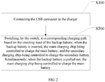
- a charging method based on the dual batteries may be further provided in the present disclosure using the charging system based on the dual batteries described above. As is shown in FIG. 2 , the charging method based on the dual batteries may include the following blocks.
- the USB connector may be connected to the charger.
- the switch may switch to the corresponding charging path based on the inserting state of the backup battery.
- the main charging chip When the backup battery is inserted, the main charging chip may be controlled to charge the main battery, and the secondary charging chip may be controlled to charge the secondary battery simultaneously.
- the main charging chip When the backup battery is pulled out, the main charging chip may be controlled to charge the main battery.
- the charge controlling unit may control the secondary battery to charge the main battery, and the charge controlling unit may be connected to the secondary charging chip.
- block S110 may further include the following blocks.
- a charge initiating instruction may be input by the power key.
- the MCU may initiate the secondary charging chip based on the charge initiating instruction, and control the secondary battery to charge the main battery.
- the current power level information of the secondary battery may be displayed by the LED lighting set.
- a mobile terminal may be further provided in the present disclosure.
- the mobile terminal may include the charging system based on the dual batteries descirbed above. Since the charging system based on the dual batteries has been described in detail, the charging system will not be described in detail any more.
- the present disclosure provides the charging system, the charging method and the mobile terminal based on the dual batteries.
- the charging system based on the dual batteries may include a main board and a backup battery. Wherein a main charging chip and a main battery may be arranged on the main board, and a secondary charging chip and a secondary battery may be arranged on the backup battery.
- a USB connector configured to connect to a charger, and a switch configured to switch to a corresponding charging path based on an inserting state of the backup battery may be further provided on the main board.
- the main charging chip may be controlled to charge the main battery, and the secondary charging chip may be controlled to charge the secondary battery simultaneously.
- the main charging chip may be controlled to charge the main battery. Therefore, it is possible to switch to the corresponding charging path based on the inserting state of the backup battery, thereby achieving the one-to-many solution, charging the main battery and the secondary battery simulteneously, and improving the charging effiency greatly.
Landscapes
- Engineering & Computer Science (AREA)
- Power Engineering (AREA)
- Manufacturing & Machinery (AREA)
- Chemical & Material Sciences (AREA)
- Chemical Kinetics & Catalysis (AREA)
- Electrochemistry (AREA)
- General Chemical & Material Sciences (AREA)
- Business, Economics & Management (AREA)
- Emergency Management (AREA)
- Charge And Discharge Circuits For Batteries Or The Like (AREA)
Description
- Embodiments of the present disclosure generally relate to mobile terminal charging technology, and in particular relate to a charging system, a charging method, and a mobile terminal based on dual batteries.
- With the increasing requirements of customers for longer battery lives of smartphones, high-capacity batteries or dual batteries may be used in the smartphones, which can well meet the requirements of the customer for extending battery lives of the smartphones. However, in the smartphones having dual batteries on the market, a main battery and a secondary battery cannot be charged simultaneously, which brings inconvenience for users.
- Therefore, the technical solution in the prior art needs to be developed and improved.
-
CN 101867198 B discloses a realizing device and a control method for a standby battery of a mobile phone. Structurally, a secondary battery, namely an external standby battery, can be flexibly combined with and dismantled from a main battery of the mobile phone. When the standby battery is arranged on the mobile phone of a user, whether the secondary battery is required to charge the main battery can be determined according to the electric quantity relationship between the main battery and the secondary battery of the mobile phone, and no extra charging equipment is required to charge the secondary battery. The secondary battery is directly arranged on the mobile phone and then can be charged by a normal mobile phone charger. -
CN 201282451 Y discloses a mobile terminal with a back up battery for power supply. The mobile terminal comprises a casing, a circuit of a mobile terminal host, a main battery and a charging circuit. The circuit of the mobile terminal host, the main battery and the charging circuit are arranged inside the casing; the main battery is connected with the circuit of the mobile terminal host; the charging circuit is connected with the main battery and the circuit of the mobile terminal host; a back up battery and a selector switch are further arranged in the casing; the charging circuit is connected with the backup battery; and the change-over switch is connected between the backup battery and the circuit of the mobile terminal host. In case of emergency, a device can go on operating by using the backup battery even if the main battery is exhausted, thereby provide convenience for users. -
US 2014/192481 A1 discloses a case for an electronic device. The case includes a battery, an interface to receive electrical current from an external power source, and a computer processor. The computer processor is configured to execute computer-readable instructions to receive a communication from the electronic device, limit the received electrical current to a current limit, and allocate the electrical current among the battery and the electronic device based on the received communication. - Aiming at defects in the prior art that the main battery and the secondary battery cannot be charged simultaneously, or the like, an objective of the present disclosure is to provide a charging system, a charging method and a mobile terminal based on dual batteries, which are capable of switching to a corresponding charging path based on an inserting state of a backup battery integrated on a back cover, achieving a one-to-many charging solution, charging the main battery and the secondary battery simulteneously, and the greatly improving charging efficiency.
- To achive the above objective, the following technical solution may be utilized in the present disclosure.
- According to one aspect of the present disclosure, a charging method based on dual batteries is provided, the charging method comprises the following.
- A0, Controlling, by a charge controlling unit, a secondary battery to charge a main battery, when a charger is not connected; the charge controlling unit being connected to a secondary charging chip; the charge controlling unit further comprising an LED light set configured to display current power level information of the secondary battery;
- A, Connecting a USB connector to a charger;
- B, Switching, by a switch, to a corresponding charging path, based on an inserting state of a backup battery; when the backup battery is inserted, controlling a main charging chip to charge the main battery, and controlling the secondary charging chip to charge the secondary battery simultaneously; when the backup battery is pulled out, controlling the main charging chip to charge the main battery. The secondary charging chip is further connected to the main charging chip. In the step B, when the backup battery is inserted and the switch switches to the secondary charging chip, the charger charges to the secondary charging chip via the USB connector, and the secondary charging chip is controlled to charge the main charging chip simultaneously.
- In some embodiments, the step A0 further comprises: A01, inputting, by a power key, a charge initiating instruction; A02, initiating, by an MCU, the secondary charging chip based on the charge initiating instruction, and controlling the secondary battery to charge the main battery.
- According to another aspect of the present disclousure, a charging system based on dual batteries is further provided. The charging system comprises a main board and a backup battery; the main board has a main charging chip and a main battery arranged thereon; the backup battery has a secondary charging chip and a secondary battery arranged thereon; the main board further comprises the following.
- A USB connector, configured to connect to a charger; and
A switch, configured to switch to a corresponding charging path based on an inserting state of the backup battery; when the backup battery is inserted, the main charging chip being controlled to charge the main battery, and the secondary charging chip being controlled to charge the secondary battery simultaneously; when the backup battery is pulled out, the main charging chip being controlled to charge the main battery;
The switch is connected to the USB connector, the main charging chip and the secondary charging chip; the main charging chip is further connected to the main battery; the secondary chargin chip is further connected to the secondary battery. The secondary charging chip is further connected to the main charging chip; when the backup battery is inserted and the switch switches to the secondary charging chip, the charger charges to the secondary charging chip via the USB connector, and the secondary charging chip is controlled to charge the main charging chip simultaneously. - In some embodiments, a charge controlling unit is further arranged on the backup battery; the charge controlling unit is configured to control the secondary battery to charge the main battery when the connector is not connected; the charge controlling unit is connected to the secondary charging chip.
- In some embodiments, the charge controlling unit further comprises: a power key, configured to input a charge initiating instruction; and an MCU, configured to initiate the secondary charging chip based on the charge initiating instruction, and control the secondary battery to charge the main battery. The MCU is connected to the power key and the secondary charging chip.
- In some embodiments, the charge controlling unit further comprises an LED light set configured to display current power level information of the secondary battery; the LED light set is connected to the MCU.
- In some embodiments, the MCU has a model of MSP430G2332.
- In some embodiments, the LED lighting set comprises a plurality of LED lamp beads, and a quantity of the LED lamp beads currently illuminated is in proportion to a current power level of the secondary battery.
- According to another aspect of the present disclousure, a mobile terminal is further provided. The mobile terminal comprises the charging system based on the dual batteries described above.
- Compared with the prior art, the present disclosure provides a charging system, a charging method and a mobile terminal based on the dual batteries. The charging system based on the dual batteries may comprise a main board and a backup battery. Wherein a main charging chip and a main battery may be arranged on the main board, and a secondary charging chip and a secondary battery may be arranged on the backup battery. A USB connector configured to connect to a charger, and a switch configured to switch to a corresponding charging path based on an inserting state of the backup battery may be further provided on the main board. When the backup battery is inserted, the main charging chip may be controlled to charge the main battery, and the secondary charging chip may be controlled to charge the secondary battery simultaneously. When the backup battery is pulled out, the main charging chip may be controlled to charge the main battery. Therefore, it is possible to switch to the corresponding charging path based on the inserting state of the backup battery, thereby achieving the one-to-many solution, charging the main battery and the secondary battery simulteneously, and improving the charging effiency greatly
- The invention is set out in the appended set of claims.
-
-
FIG. 1 is a block diagram showing a charging system based on dual batteries of the present disclosure. -
FIG. 2 is a flow chart of a charging method based on the dual batteries of the present disclosure. - Aiming at defects in the prior art that the main battery and the secondary battery cannot be charged simultaneously, or the like, an objective of the present disclosure is to provide a charging system, a charging method and a mobile terminal based on dual batteries, which are capable of switching to a corresponding charging path based on an inserting state of a backup battery integrated on a back cover. In this way, it is possible to achieve a one-to-many charging solution, the main battery and the secondary battery may be charged simulteneously, and the charging efficiency may be greatly improved.
- In order to make the technical solution described in the embodiments of the present application more clearly and definitely, the technical solution of the present disclosure will be described in detail with reference to the drawings and embodiments. It should be understood that, the embodiments described below are only used for explanation, not for limitation.
- Referring to
FIG. 1 , a charging system based on dual batteries provided in the present disclosure may include amainboard 10 and abackup battery 20 integrated on a back cover. Themain board 10 may have amain charging chip 11 and a main battery 12 arranged thereon, and may be configured as main power souce of a mobile terminal to supply power to the mobile terminal. Thebackup battery 20 may have asecondary charging chip 21 and asecondary battery 22 arranged thereon, and may be configured as backup power souce of the mobile terminal to supply power to the mobile terminal. The techincal solution having dual batteries may meet the requirements of battery lives. In this embodiment, aUSB connector 13 and aswitch 14 may be further arranged on themain board 10. Theswitch 14 may be respectively connected to theUSB connector 13, themain charging chip 11 and thesecondary charging chip 21. Themain charging chip 11 may be further connected to the main battery 12, and thesecondary charging chip 21 may be further connected to thesecondary battery 22. TheUSB connector 13 may be configured to connect to a charger. Theswitch 14 may be configured to switch to a corresponding charging path based on an inserting state of thebackup battery 20. When thebackup battery 20 is inserted, themain charging chip 11 may be controlled to charge the main battery 12, and thesecondary charging chip 21 may be controlled to charge thesecondary battery 22 simultaneously. When thebackup battery 20 is pulled out, themain charging chip 11 may be controlled to charge the main battery 12. Therefore, it is possible to select the current charging path based on whether thebackup battery 20 is inserted currently. When thebackup battery 20 is inserted, it is possible to achieve the one-to-many solution which charges the main battery 12 and thesecondary battery 22 simulteneously, thereby greatly improving the charging effiency. Optionally, thesecondary battery 22 may have a capacity of 3000mAh; themain charging chip 11 may have a model of BQ2429X, while thesecondary charging chip 21 may have a model of BQ24295. Of course, other charging chips having the same functions may also be implemented, and the present disclosure may not be intended to limit the model of the chip. - Furthermore, a
charge controlling unit 23 may be further arranged on thebackup battery 20. Thecharge controlling unit 23 may be connected to thesecondary charging chip 21, and configured to control thesecondary battery 22 to charge the main battery 12 when the charger is not connected. That is, when the charging system is not connected to the charger, and thesecondary battery 22 still has power, thecharge controlling unit 23 may control thesecondary battery 22 to charge the main battery 12. In this way, the mobile terminal may be supplied with power, and it is possible to ensure that the battery life of the mobile terminal may be extended normally, and running time of the mobile phone may be extended. - In practical application, the charging paths may be indicated by three line segments having arrows shown in
FIG. 1 . When thebackup battery 20 is inserted, themain charging chip 11 may be controlled to charge the main battery 12, and thesecondary charging chip 21 may be controlled to charge thesecondary battery 22. At this time, theswitch 14 may switch the paths, in such a way that the charging path may travel along a full line path (i.e., path OUT2) shown inFIG. 1 . The charging path may travel along the components in following orders: the charger - the USB connector 13 - the switch 14 - a POGO Pin (Vbus2_pin) arranged between themain board 10 and the backup battery 20 - a Vbus2 pin of thesecondary charging chip 21. The charging path may further travel along the components in the following orders: the charger - the USB connector 13 - the switch 14 - the POGO Pin (Vbus2_pin) arranged between themain board 10 and the backup battery 20 - the Vbus2 pin of the secondary charging chip 21 - a PMID pin of the secondary charging chip 21 - a POGO Pin (PMID_pin) arranged between themain board 10 and the backup battery 20 - a Vbus1 pin of the main charging chip 11 - the main battery 12/ themain board 10. In this way, the main battery 12 and thesecondary battery 22 may be charged simultaneously. - When the
backup battery 20 is not inserted, or when the back cover is a common back cover without thesecondary battery 22 integrated thereon, themain charging chip 11 may be controlled to charge the main battery 12. At this time, theswitch 14 may switch the paths, in such a way that the charging path may travel along an intensive broken line path (i.e., path OUT1) shown inFIG. 1 . The charging path may travel along the components in the following orders: the charger - the USB connector 13 - the switch 14 - the Vbus1 pin of the main charging chip 11 - the main battery 12. In this way, the main battery 12 may be charged by the charger. - When the charger is not connected, and the
backup battery 20 has been inserted, thesecondary battery 22 may be controlled to charge the main battery 12, and the charging path may travel along a sparse broken line path shown inFIG. 1 . The charging path may travel along the components in the following orders: the secondary battery 22 - the PMID pin of the secondary charging chip 21- the POGO Pin (PMID_pin) arranged between themain board 10 and the backup battery - the Vbus1 pin of the main charging chip 11 - the main battery 12/ themain board 10. In this way, thesecondary battery 22 may supply power to themain board 10 and further charge the main battery 12, and thus the requirement of the user for the battery life may be met. - In specific, the
charge controlling unit 23 may include apower key 231, an MCU and an LED light set 233. TheMCU 232 may be connected to thepower key 231 and thesecondary charging chip 21. The LED light set 233 may be connected to theMCU 232. Wherein thepower key 231 may be configured to input a charge initiating instruction. TheMCU 232 may be configured to initiate thesecondary charging chip 21 based on the charge initiating instruction, and control thesecondary battery 22 to charge the main battery 12. The LED light set 233 may be configured to display current power level information of thesecondary battery 22. Thepower key 231 may be a physical button arranged on thebackup battery 20. Instruction information input by the button may be defined. For example, when the button is shortly pressed down, the charge initiating instruction may be input. However, when the button is pressed down for a period of time longer than a preset period of time (such as 3s), a charge ending instruction may be input. When theMCU 232 receives the charge initiating instruction, thesecondary charging chip 21 may be initiated, and thus thesecondary battery 22 may be controlled to supply power to themain board 10 and further charge the main battery 12 based on the path indicated by the sparse broken line. Meanwhile, in order to make the user clearly know the current power level of thesecondary battery 22 and estimate the remaining battery life, the LED lighting set 233 having a plurality of LED lamp beads may be further provided to display the current power level information of thesecondary battery 22. That is, the quantity of the LED lamp beads currently illuminated may be in proportion to the power level of thesecondary battery 22, and thus the user may clearly know the currently remaining power level of thesecondary battery 22 at one glance. Optionally, four LED lamp beads may be provided. Of course, the quantity of the LED lamp beads may be increased or decreased as required. In this embodiment, theMCU 232 may have a model of MSP430G2332, and the LED light set 233 may include a plurality of surface-mount LEDs having a model of LED0603. - Optionally, a low dropout linear regulator LD0 (not shown in the drawings) configured to regulate voltages and an over-current protective chip (not shown in the drawings) configured to provide current-limiting protection may be further arranged on the
backup battery 20, in order to ensure the stability and security of charging. The low dropout linear regulator LD0 may have a model of SGM2021_3Y, while the over-current protective chip may have a modle of TPS2553. - A charging method based on the dual batteries may be further provided in the present disclosure using the charging system based on the dual batteries described above. As is shown in
FIG. 2 , the charging method based on the dual batteries may include the following blocks. - At block S100, the USB connector may be connected to the charger.
- At block S200, the switch may switch to the corresponding charging path based on the inserting state of the backup battery. When the backup battery is inserted, the main charging chip may be controlled to charge the main battery, and the secondary charging chip may be controlled to charge the secondary battery simultaneously. When the backup battery is pulled out, the main charging chip may be controlled to charge the main battery.
- Before the block SI00, a further block may be provided.
- At block SIIO, when the charger is not connected, the charge controlling unit may control the secondary battery to charge the main battery, and the charge controlling unit may be connected to the secondary charging chip.
- In specific, the block S110 may further include the following blocks.
- At block S111, a charge initiating instruction may be input by the power key.
- At block S112, the MCU may initiate the secondary charging chip based on the charge initiating instruction, and control the secondary battery to charge the main battery.
- At block S113, the current power level information of the secondary battery may be displayed by the LED lighting set.
- Specific embodiments concerning the switch of the paths and the charging control may refer to the corresponding embodiments of the charging system aforesaid.
- A mobile terminal may be further provided in the present disclosure. The mobile terminal may include the charging system based on the dual batteries descirbed above. Since the charging system based on the dual batteries has been described in detail, the charging system will not be described in detail any more.
- In conclusion, the present disclosure provides the charging system, the charging method and the mobile terminal based on the dual batteries. The charging system based on the dual batteries may include a main board and a backup battery. Wherein a main charging chip and a main battery may be arranged on the main board, and a secondary charging chip and a secondary battery may be arranged on the backup battery. A USB connector configured to connect to a charger, and a switch configured to switch to a corresponding charging path based on an inserting state of the backup battery may be further provided on the main board. When the backup battery is inserted, the main charging chip may be controlled to charge the main battery, and the secondary charging chip may be controlled to charge the secondary battery simultaneously. When the backup battery is pulled out, the main charging chip may be controlled to charge the main battery. Therefore, it is possible to switch to the corresponding charging path based on the inserting state of the backup battery, thereby achieving the one-to-many solution, charging the main battery and the secondary battery simulteneously, and improving the charging effiency greatly.
Claims (9)
- A charging method based on dual batteries, comprising:A0, controlling, by a charge controlling unit (23), a secondary battery (22) to charge a main battery (12), when a charger is not connected; the charge controlling unit (23) being connected to a secondary charging chip (21); the charge controlling unit (23) further comprising an LED light set (233) configured to display current power level information of the secondary battery (22);A, connecting a USB connector (13) to a charger;B, switching, by a switch (14), to a corresponding charging path, based on an inserting state of a backup battery (20); when the backup battery (20) is inserted, controlling a main charging chip (11) to charge the main battery (12), and controlling the secondary charging chip (21) to charge the secondary battery (22) simultaneously; when the backup battery (20) is pulled out, controlling the main charging chip (11) to charge the main battery (12);characterized in that, the secondary charging chip (21) is further connected to the main charging chip (11); in the step B, when the backup battery (20) is inserted and the switch (14) switches to the secondary charging chip (21), the charger charges to the secondary charging chip (21) via the USB connector (13), and the secondary charging chip (21) is controlled to charge the main charging chip (11) simultaneously.
- The charging method based on the dual batteries of claim 1, wherein the step A0 further comprises:A01, inputting, by a power key (231), a charge initiating instruction;A02, initiating, by an MCU (232), the secondary charging chip (21) based on the charge initiating instruction, and controlling the secondary battery (22) to charge the main battery (12).
- A charging system based on dual batteries, comprising a main board and a backup battery (20); the main board having a main charging chip (11) and a main battery (12) arranged thereon; the backup battery (20) having a secondary charging chip (21) and a secondary battery (22) arranged thereon; the main board further comprising:a USB connector (13), configured to connect to a charger; anda switch (14), configured to switch (14) to a corresponding charging path based on an inserting state of the backup battery (20); when the backup battery (20) is inserted, the main charging chip (11) being controlled to charge the main battery (12), and the secondary charging chip (21) being controlled to charge the secondary battery (22) simultaneously; when the backup battery (20) is pulled out, the main charging chip (11) being controlled to charge the main battery (12);the switch (14) being connected to the USB connector (13), the main charging chip (11) and the secondary charging chip (21); the main charging chip (11) being further connected to the main battery (12); the secondary charging chip being further connected to the secondary battery (22);characterized in that, the secondary charging chip (21) is further connected to the main charging chip (11); when the backup battery (20) is inserted and the switch (14) switches to the secondary charging chip (21), the charger charges to the secondary charging chip (21) via the USB connector (13), and the secondary charging chip (21) is controlled to charge the main charging chip (11) simultaneously.
- The charging system based on the dual batteries of claim 3, wherein a charge controlling unit (23) is further arranged on the backup battery (20); the charge controlling unit (23) is configured to control the secondary battery (22) to charge the main battery (12) when the connector is not connected; the charge controlling unit (23) is connected to the secondary charging chip (21).
- The charging system based on the dual batteries of claim 3, wherein the charge controlling unit (23) further comprises:a power key (231), configured to input a charge initiating instruction; andan MCU (232), configured to initiate the secondary charging chip (21) based on the charge initiating instruction, and control the secondary battery (22) to charge the main battery (12);the MCU (232) is connected to the power key (231) and the secondary charging chip (21).
- The charging system based on the dual batteries of claim 5, wherein the charge controlling unit (23) further comprises an LED light set (233) configured to display current power level information of the secondary battery (22); the LED light set (233) is connected to the MCU (232).
- The charging system based on the dual batteries of claim 5, wherein the MCU (232) has a model of MSP430G2332.
- The charging system based on the dual batteries of claim 6, wherein the LED lighting set (233) comprises a plurality of LED lamp beads, and a quantity of the LED lamp beads currently illuminated is in proportion to a current power level of the secondary battery (22).
- A mobile terminal, comprising the charging system based on the dual batteries of any one of claims 3-8.
Applications Claiming Priority (2)
| Application Number | Priority Date | Filing Date | Title |
|---|---|---|---|
| CN201610852486.0A CN106385067A (en) | 2016-09-27 | 2016-09-27 | Double-battery-based charging system, method and mobile terminal |
| PCT/CN2017/080880 WO2018058940A1 (en) | 2016-09-27 | 2017-04-18 | Dual battery-based charging system, method, and mobile terminal |
Publications (3)
| Publication Number | Publication Date |
|---|---|
| EP3522327A4 EP3522327A4 (en) | 2019-08-07 |
| EP3522327A1 EP3522327A1 (en) | 2019-08-07 |
| EP3522327B1 true EP3522327B1 (en) | 2021-03-24 |
Family
ID=57935992
Family Applications (1)
| Application Number | Title | Priority Date | Filing Date |
|---|---|---|---|
| EP17825724.2A Active EP3522327B1 (en) | 2016-09-27 | 2017-04-18 | Dual battery-based charging system, method, and mobile terminal |
Country Status (4)
| Country | Link |
|---|---|
| US (1) | US10886756B2 (en) |
| EP (1) | EP3522327B1 (en) |
| CN (1) | CN106385067A (en) |
| WO (1) | WO2018058940A1 (en) |
Families Citing this family (10)
| Publication number | Priority date | Publication date | Assignee | Title |
|---|---|---|---|---|
| CN107294157B (en) * | 2017-06-07 | 2021-07-13 | 惠州Tcl移动通信有限公司 | A mobile terminal, self-charging method and storage device |
| US11258280B2 (en) | 2017-07-21 | 2022-02-22 | Huawei Technologies Co., Ltd. | Mobile terminal, peripheral device, and charging method thereof |
| CN110718944B (en) * | 2018-07-12 | 2023-08-04 | 中兴通讯股份有限公司 | A method, device, terminal and storage medium for charging and discharging a dual battery |
| CN109193830A (en) * | 2018-09-07 | 2019-01-11 | 杭州电子科技大学 | A kind of battery of mobile phone method of supplying power to |
| CN111464672A (en) * | 2019-01-18 | 2020-07-28 | 青岛海信移动通信技术股份有限公司 | An electronic device and charging method thereof |
| CN110277813B (en) | 2019-06-13 | 2021-03-23 | 华为技术有限公司 | foldable electronic device |
| CN110707388B (en) * | 2019-09-16 | 2021-09-03 | Tcl移动通信科技(宁波)有限公司 | Charging method, charging device, storage medium and electronic equipment |
| CN112346701A (en) * | 2020-11-06 | 2021-02-09 | 刘延黄 | Desktop type wireless live broadcast sound card equipment |
| CN115333194A (en) * | 2022-08-19 | 2022-11-11 | 读书郎教育科技有限公司 | Split type terminal and method capable of realizing charging reminding |
| KR102807247B1 (en) * | 2023-01-16 | 2025-05-16 | 주식회사 이노아이티 | Multi-battery control system for aerosol generator |
Family Cites Families (21)
| Publication number | Priority date | Publication date | Assignee | Title |
|---|---|---|---|---|
| KR970024434A (en) * | 1995-10-12 | 1997-05-30 | 김광호 | Combined Battery Charger and Control Method |
| JP3976268B2 (en) * | 2003-11-28 | 2007-09-12 | インターナショナル・ビジネス・マシーンズ・コーポレーション | Battery pack, electrical device, computer apparatus, battery control method, power supply method, and program |
| US7535196B2 (en) * | 2004-01-22 | 2009-05-19 | Nec Corporation | Power apparatus and electronic equipment for cellular phone having main battery and attachable battery |
| JP4779167B2 (en) | 2008-03-19 | 2011-09-28 | 奇美電子股▲ふん▼有限公司 | Method for driving liquid crystal display device, overdrive correction device, data creation method for overdrive correction device, liquid crystal display device, and electronic device |
| CN201170892Y (en) * | 2008-04-22 | 2008-12-24 | 怡利电子工业股份有限公司 | Portable Electronic Device Battery Structure |
| CN201282451Y (en) * | 2008-10-16 | 2009-07-29 | 上海华勤通讯技术有限公司 | Mobile terminal with back-up battery power supply |
| CN101867198B (en) | 2009-04-20 | 2012-11-28 | 龙旗科技(上海)有限公司 | Realizing device and control method for standby battery of mobile phone |
| CN102004538B (en) * | 2009-08-31 | 2014-03-26 | 鸿富锦精密工业(深圳)有限公司 | Notebook computer power supply circuit |
| CN102025001B (en) * | 2009-09-21 | 2013-07-31 | 联想(北京)有限公司 | Terminal and charging and power supplying method thereof |
| US8390254B2 (en) * | 2010-03-31 | 2013-03-05 | Winmate Communication Inc. | Charging apparatus for laptop computer with multi-batteries and method for the same |
| KR101255904B1 (en) * | 2011-05-04 | 2013-04-17 | 삼성전기주식회사 | Power charging apparatus and charging method for both wireline and wireless |
| US20120319487A1 (en) * | 2011-06-16 | 2012-12-20 | Rakesh Shah | Integrated Battery Backup and Charging for Mobile Devices |
| CN202309150U (en) | 2011-11-01 | 2012-07-04 | 宁波大红鹰学院 | Power supply device of cellphone with double cells |
| CN103403643B (en) * | 2012-06-27 | 2016-03-02 | 华为终端有限公司 | Management of charging and discharging device and mobile terminal |
| CN103581371B (en) * | 2012-08-10 | 2017-03-22 | 中兴通讯股份有限公司 | Mobile terminal and battery control method thereof |
| JP2014059619A (en) * | 2012-09-14 | 2014-04-03 | Panasonic Corp | Electronic apparatus |
| US9231410B2 (en) * | 2013-01-04 | 2016-01-05 | Otter Products, Llc | Electronic device case |
| CN204145000U (en) * | 2014-09-18 | 2015-02-04 | 青岛海信智能商用系统有限公司 | The adjustable charging circuit of charging current and there is the electronic product of this charging circuit |
| CN204809896U (en) * | 2015-05-20 | 2015-11-25 | 北京联云格科技有限公司 | Incessant power supply system and equipment |
| CN105914839B (en) * | 2016-05-31 | 2019-06-21 | 深圳埃蒙克斯科技有限公司 | A dual-battery mobile phone and its battery control method and system |
| CN106451616B (en) | 2016-09-27 | 2020-03-06 | Tcl通讯(宁波)有限公司 | Mobile terminal and double-battery charging switching circuit, system and method thereof |
-
2016
- 2016-09-27 CN CN201610852486.0A patent/CN106385067A/en active Pending
-
2017
- 2017-04-18 EP EP17825724.2A patent/EP3522327B1/en active Active
- 2017-04-18 WO PCT/CN2017/080880 patent/WO2018058940A1/en not_active Ceased
- 2017-04-18 US US15/745,989 patent/US10886756B2/en active Active
Non-Patent Citations (1)
| Title |
|---|
| None * |
Also Published As
| Publication number | Publication date |
|---|---|
| US10886756B2 (en) | 2021-01-05 |
| EP3522327A4 (en) | 2019-08-07 |
| US20200083721A1 (en) | 2020-03-12 |
| EP3522327A1 (en) | 2019-08-07 |
| WO2018058940A1 (en) | 2018-04-05 |
| CN106385067A (en) | 2017-02-08 |
Similar Documents
| Publication | Publication Date | Title |
|---|---|---|
| EP3522327B1 (en) | Dual battery-based charging system, method, and mobile terminal | |
| CN211296217U (en) | battery pack | |
| US9337661B2 (en) | Power management system and method | |
| CN204497772U (en) | A kind of portable power source Apparatus and system of quick electric power storage | |
| US20160218539A1 (en) | Method and apparatus for operating an internal charger system of a portable electronic device | |
| US20120178505A1 (en) | Smart charging system | |
| CN203481802U (en) | Battery protective circuit and system | |
| US20230318327A1 (en) | Stylus | |
| CN202333926U (en) | Mobile power supply | |
| US10411491B2 (en) | Charging method and electronic device using the same | |
| WO2016065822A1 (en) | Multifunctional data mobile power supply and charging method | |
| US9667072B2 (en) | Mobile power device with memory storage feature which switches between master and slave roles | |
| CN107732991A (en) | Terminal charge control method, device and terminal | |
| CN106451616B (en) | Mobile terminal and double-battery charging switching circuit, system and method thereof | |
| EP3518370A1 (en) | Dual-battery mobile terminal and wireless charging system thereof | |
| AU2020359424B2 (en) | Dynamic battery voltage restriction for hazardous environments | |
| CN102891512A (en) | Control chip of mobile power supply and working control method of mobile power supply | |
| US10481576B2 (en) | Method and device for implementing connection control | |
| CN103746423A (en) | Novel mobile power supply and preparing method thereof | |
| CN105024422A (en) | Power supply/charging arrangement method and system of controllable-user mobile intelligent terminal | |
| CN113419617A (en) | Wearable device charging reset circuit and control method | |
| CN113859552B (en) | Battery management system | |
| CN210839024U (en) | Multifunctional mobile power supply | |
| CN111162572B (en) | An electronic device and its charging circuit and charging method | |
| CN207868847U (en) | A kind of mobile power |
Legal Events
| Date | Code | Title | Description |
|---|---|---|---|
| STAA | Information on the status of an ep patent application or granted ep patent |
Free format text: STATUS: UNKNOWN |
|
| STAA | Information on the status of an ep patent application or granted ep patent |
Free format text: STATUS: THE INTERNATIONAL PUBLICATION HAS BEEN MADE |
|
| PUAI | Public reference made under article 153(3) epc to a published international application that has entered the european phase |
Free format text: ORIGINAL CODE: 0009012 |
|
| STAA | Information on the status of an ep patent application or granted ep patent |
Free format text: STATUS: REQUEST FOR EXAMINATION WAS MADE |
|
| 17P | Request for examination filed |
Effective date: 20190121 |
|
| A4 | Supplementary search report drawn up and despatched |
Effective date: 20190618 |
|
| AK | Designated contracting states |
Kind code of ref document: A1 Designated state(s): AL AT BE BG CH CY CZ DE DK EE ES FI FR GB GR HR HU IE IS IT LI LT LU LV MC MK MT NL NO PL PT RO RS SE SI SK SM TR |
|
| AX | Request for extension of the european patent |
Extension state: BA ME |
|
| DAV | Request for validation of the european patent (deleted) | ||
| DAX | Request for extension of the european patent (deleted) | ||
| GRAP | Despatch of communication of intention to grant a patent |
Free format text: ORIGINAL CODE: EPIDOSNIGR1 |
|
| STAA | Information on the status of an ep patent application or granted ep patent |
Free format text: STATUS: GRANT OF PATENT IS INTENDED |
|
| INTG | Intention to grant announced |
Effective date: 20201013 |
|
| RIN1 | Information on inventor provided before grant (corrected) |
Inventor name: DIAO, ZHIMING Inventor name: TONG, HONGJIE |
|
| GRAS | Grant fee paid |
Free format text: ORIGINAL CODE: EPIDOSNIGR3 |
|
| GRAA | (expected) grant |
Free format text: ORIGINAL CODE: 0009210 |
|
| STAA | Information on the status of an ep patent application or granted ep patent |
Free format text: STATUS: THE PATENT HAS BEEN GRANTED |
|
| AK | Designated contracting states |
Kind code of ref document: B1 Designated state(s): AL AT BE BG CH CY CZ DE DK EE ES FI FR GB GR HR HU IE IS IT LI LT LU LV MC MK MT NL NO PL PT RO RS SE SI SK SM TR |
|
| REG | Reference to a national code |
Ref country code: GB Ref legal event code: FG4D |
|
| REG | Reference to a national code |
Ref country code: CH Ref legal event code: EP |
|
| REG | Reference to a national code |
Ref country code: DE Ref legal event code: R096 Ref document number: 602017035403 Country of ref document: DE |
|
| REG | Reference to a national code |
Ref country code: IE Ref legal event code: FG4D |
|
| REG | Reference to a national code |
Ref country code: AT Ref legal event code: REF Ref document number: 1375484 Country of ref document: AT Kind code of ref document: T Effective date: 20210415 |
|
| REG | Reference to a national code |
Ref country code: LT Ref legal event code: MG9D |
|
| PG25 | Lapsed in a contracting state [announced via postgrant information from national office to epo] |
Ref country code: BG Free format text: LAPSE BECAUSE OF FAILURE TO SUBMIT A TRANSLATION OF THE DESCRIPTION OR TO PAY THE FEE WITHIN THE PRESCRIBED TIME-LIMIT Effective date: 20210624 Ref country code: HR Free format text: LAPSE BECAUSE OF FAILURE TO SUBMIT A TRANSLATION OF THE DESCRIPTION OR TO PAY THE FEE WITHIN THE PRESCRIBED TIME-LIMIT Effective date: 20210324 Ref country code: GR Free format text: LAPSE BECAUSE OF FAILURE TO SUBMIT A TRANSLATION OF THE DESCRIPTION OR TO PAY THE FEE WITHIN THE PRESCRIBED TIME-LIMIT Effective date: 20210625 Ref country code: FI Free format text: LAPSE BECAUSE OF FAILURE TO SUBMIT A TRANSLATION OF THE DESCRIPTION OR TO PAY THE FEE WITHIN THE PRESCRIBED TIME-LIMIT Effective date: 20210324 Ref country code: NO Free format text: LAPSE BECAUSE OF FAILURE TO SUBMIT A TRANSLATION OF THE DESCRIPTION OR TO PAY THE FEE WITHIN THE PRESCRIBED TIME-LIMIT Effective date: 20210624 |
|
| PG25 | Lapsed in a contracting state [announced via postgrant information from national office to epo] |
Ref country code: RS Free format text: LAPSE BECAUSE OF FAILURE TO SUBMIT A TRANSLATION OF THE DESCRIPTION OR TO PAY THE FEE WITHIN THE PRESCRIBED TIME-LIMIT Effective date: 20210324 Ref country code: LV Free format text: LAPSE BECAUSE OF FAILURE TO SUBMIT A TRANSLATION OF THE DESCRIPTION OR TO PAY THE FEE WITHIN THE PRESCRIBED TIME-LIMIT Effective date: 20210324 Ref country code: SE Free format text: LAPSE BECAUSE OF FAILURE TO SUBMIT A TRANSLATION OF THE DESCRIPTION OR TO PAY THE FEE WITHIN THE PRESCRIBED TIME-LIMIT Effective date: 20210324 |
|
| REG | Reference to a national code |
Ref country code: NL Ref legal event code: MP Effective date: 20210324 |
|
| REG | Reference to a national code |
Ref country code: AT Ref legal event code: MK05 Ref document number: 1375484 Country of ref document: AT Kind code of ref document: T Effective date: 20210324 |
|
| PG25 | Lapsed in a contracting state [announced via postgrant information from national office to epo] |
Ref country code: NL Free format text: LAPSE BECAUSE OF FAILURE TO SUBMIT A TRANSLATION OF THE DESCRIPTION OR TO PAY THE FEE WITHIN THE PRESCRIBED TIME-LIMIT Effective date: 20210324 |
|
| PG25 | Lapsed in a contracting state [announced via postgrant information from national office to epo] |
Ref country code: SM Free format text: LAPSE BECAUSE OF FAILURE TO SUBMIT A TRANSLATION OF THE DESCRIPTION OR TO PAY THE FEE WITHIN THE PRESCRIBED TIME-LIMIT Effective date: 20210324 Ref country code: AT Free format text: LAPSE BECAUSE OF FAILURE TO SUBMIT A TRANSLATION OF THE DESCRIPTION OR TO PAY THE FEE WITHIN THE PRESCRIBED TIME-LIMIT Effective date: 20210324 Ref country code: CZ Free format text: LAPSE BECAUSE OF FAILURE TO SUBMIT A TRANSLATION OF THE DESCRIPTION OR TO PAY THE FEE WITHIN THE PRESCRIBED TIME-LIMIT Effective date: 20210324 Ref country code: EE Free format text: LAPSE BECAUSE OF FAILURE TO SUBMIT A TRANSLATION OF THE DESCRIPTION OR TO PAY THE FEE WITHIN THE PRESCRIBED TIME-LIMIT Effective date: 20210324 Ref country code: LT Free format text: LAPSE BECAUSE OF FAILURE TO SUBMIT A TRANSLATION OF THE DESCRIPTION OR TO PAY THE FEE WITHIN THE PRESCRIBED TIME-LIMIT Effective date: 20210324 |
|
| PG25 | Lapsed in a contracting state [announced via postgrant information from national office to epo] |
Ref country code: IS Free format text: LAPSE BECAUSE OF FAILURE TO SUBMIT A TRANSLATION OF THE DESCRIPTION OR TO PAY THE FEE WITHIN THE PRESCRIBED TIME-LIMIT Effective date: 20210724 Ref country code: SK Free format text: LAPSE BECAUSE OF FAILURE TO SUBMIT A TRANSLATION OF THE DESCRIPTION OR TO PAY THE FEE WITHIN THE PRESCRIBED TIME-LIMIT Effective date: 20210324 Ref country code: RO Free format text: LAPSE BECAUSE OF FAILURE TO SUBMIT A TRANSLATION OF THE DESCRIPTION OR TO PAY THE FEE WITHIN THE PRESCRIBED TIME-LIMIT Effective date: 20210324 Ref country code: PL Free format text: LAPSE BECAUSE OF FAILURE TO SUBMIT A TRANSLATION OF THE DESCRIPTION OR TO PAY THE FEE WITHIN THE PRESCRIBED TIME-LIMIT Effective date: 20210324 Ref country code: PT Free format text: LAPSE BECAUSE OF FAILURE TO SUBMIT A TRANSLATION OF THE DESCRIPTION OR TO PAY THE FEE WITHIN THE PRESCRIBED TIME-LIMIT Effective date: 20210726 |
|
| PG25 | Lapsed in a contracting state [announced via postgrant information from national office to epo] |
Ref country code: LU Free format text: LAPSE BECAUSE OF NON-PAYMENT OF DUE FEES Effective date: 20210418 |
|
| REG | Reference to a national code |
Ref country code: DE Ref legal event code: R097 Ref document number: 602017035403 Country of ref document: DE |
|
| REG | Reference to a national code |
Ref country code: BE Ref legal event code: MM Effective date: 20210430 |
|
| PG25 | Lapsed in a contracting state [announced via postgrant information from national office to epo] |
Ref country code: MC Free format text: LAPSE BECAUSE OF FAILURE TO SUBMIT A TRANSLATION OF THE DESCRIPTION OR TO PAY THE FEE WITHIN THE PRESCRIBED TIME-LIMIT Effective date: 20210324 Ref country code: LI Free format text: LAPSE BECAUSE OF NON-PAYMENT OF DUE FEES Effective date: 20210430 Ref country code: AL Free format text: LAPSE BECAUSE OF FAILURE TO SUBMIT A TRANSLATION OF THE DESCRIPTION OR TO PAY THE FEE WITHIN THE PRESCRIBED TIME-LIMIT Effective date: 20210324 Ref country code: DK Free format text: LAPSE BECAUSE OF FAILURE TO SUBMIT A TRANSLATION OF THE DESCRIPTION OR TO PAY THE FEE WITHIN THE PRESCRIBED TIME-LIMIT Effective date: 20210324 Ref country code: CH Free format text: LAPSE BECAUSE OF NON-PAYMENT OF DUE FEES Effective date: 20210430 Ref country code: ES Free format text: LAPSE BECAUSE OF FAILURE TO SUBMIT A TRANSLATION OF THE DESCRIPTION OR TO PAY THE FEE WITHIN THE PRESCRIBED TIME-LIMIT Effective date: 20210324 |
|
| PLBE | No opposition filed within time limit |
Free format text: ORIGINAL CODE: 0009261 |
|
| STAA | Information on the status of an ep patent application or granted ep patent |
Free format text: STATUS: NO OPPOSITION FILED WITHIN TIME LIMIT |
|
| PG25 | Lapsed in a contracting state [announced via postgrant information from national office to epo] |
Ref country code: SI Free format text: LAPSE BECAUSE OF FAILURE TO SUBMIT A TRANSLATION OF THE DESCRIPTION OR TO PAY THE FEE WITHIN THE PRESCRIBED TIME-LIMIT Effective date: 20210324 |
|
| 26N | No opposition filed |
Effective date: 20220104 |
|
| PG25 | Lapsed in a contracting state [announced via postgrant information from national office to epo] |
Ref country code: IE Free format text: LAPSE BECAUSE OF NON-PAYMENT OF DUE FEES Effective date: 20210418 |
|
| PG25 | Lapsed in a contracting state [announced via postgrant information from national office to epo] |
Ref country code: IS Free format text: LAPSE BECAUSE OF FAILURE TO SUBMIT A TRANSLATION OF THE DESCRIPTION OR TO PAY THE FEE WITHIN THE PRESCRIBED TIME-LIMIT Effective date: 20210724 |
|
| PG25 | Lapsed in a contracting state [announced via postgrant information from national office to epo] |
Ref country code: BE Free format text: LAPSE BECAUSE OF NON-PAYMENT OF DUE FEES Effective date: 20210430 |
|
| PG25 | Lapsed in a contracting state [announced via postgrant information from national office to epo] |
Ref country code: IT Free format text: LAPSE BECAUSE OF FAILURE TO SUBMIT A TRANSLATION OF THE DESCRIPTION OR TO PAY THE FEE WITHIN THE PRESCRIBED TIME-LIMIT Effective date: 20210324 |
|
| PG25 | Lapsed in a contracting state [announced via postgrant information from national office to epo] |
Ref country code: CY Free format text: LAPSE BECAUSE OF FAILURE TO SUBMIT A TRANSLATION OF THE DESCRIPTION OR TO PAY THE FEE WITHIN THE PRESCRIBED TIME-LIMIT Effective date: 20210324 |
|
| P01 | Opt-out of the competence of the unified patent court (upc) registered |
Effective date: 20230530 |
|
| PG25 | Lapsed in a contracting state [announced via postgrant information from national office to epo] |
Ref country code: HU Free format text: LAPSE BECAUSE OF FAILURE TO SUBMIT A TRANSLATION OF THE DESCRIPTION OR TO PAY THE FEE WITHIN THE PRESCRIBED TIME-LIMIT; INVALID AB INITIO Effective date: 20170418 |
|
| PG25 | Lapsed in a contracting state [announced via postgrant information from national office to epo] |
Ref country code: MK Free format text: LAPSE BECAUSE OF FAILURE TO SUBMIT A TRANSLATION OF THE DESCRIPTION OR TO PAY THE FEE WITHIN THE PRESCRIBED TIME-LIMIT Effective date: 20210324 |
|
| PG25 | Lapsed in a contracting state [announced via postgrant information from national office to epo] |
Ref country code: MT Free format text: LAPSE BECAUSE OF FAILURE TO SUBMIT A TRANSLATION OF THE DESCRIPTION OR TO PAY THE FEE WITHIN THE PRESCRIBED TIME-LIMIT Effective date: 20210324 |
|
| PGFP | Annual fee paid to national office [announced via postgrant information from national office to epo] |
Ref country code: DE Payment date: 20250422 Year of fee payment: 9 |
|
| PGFP | Annual fee paid to national office [announced via postgrant information from national office to epo] |
Ref country code: FR Payment date: 20250425 Year of fee payment: 9 |
|
| PG25 | Lapsed in a contracting state [announced via postgrant information from national office to epo] |
Ref country code: TR Free format text: LAPSE BECAUSE OF FAILURE TO SUBMIT A TRANSLATION OF THE DESCRIPTION OR TO PAY THE FEE WITHIN THE PRESCRIBED TIME-LIMIT Effective date: 20210324 |
|
| PGFP | Annual fee paid to national office [announced via postgrant information from national office to epo] |
Ref country code: GB Payment date: 20260306 Year of fee payment: 10 |