EP3522259B1 - Venting device for a battery system - Google Patents
Venting device for a battery system Download PDFInfo
- Publication number
- EP3522259B1 EP3522259B1 EP18154607.8A EP18154607A EP3522259B1 EP 3522259 B1 EP3522259 B1 EP 3522259B1 EP 18154607 A EP18154607 A EP 18154607A EP 3522259 B1 EP3522259 B1 EP 3522259B1
- Authority
- EP
- European Patent Office
- Prior art keywords
- venting device
- connection element
- complementary
- battery module
- module housing
- Prior art date
- Legal status (The legal status is an assumption and is not a legal conclusion. Google has not performed a legal analysis and makes no representation as to the accuracy of the status listed.)
- Active
Links
Images




Classifications
-
- H—ELECTRICITY
- H01—ELECTRIC ELEMENTS
- H01M—PROCESSES OR MEANS, e.g. BATTERIES, FOR THE DIRECT CONVERSION OF CHEMICAL ENERGY INTO ELECTRICAL ENERGY
- H01M50/00—Constructional details or processes of manufacture of the non-active parts of electrochemical cells other than fuel cells, e.g. hybrid cells
- H01M50/30—Arrangements for facilitating escape of gases
-
- H—ELECTRICITY
- H01—ELECTRIC ELEMENTS
- H01M—PROCESSES OR MEANS, e.g. BATTERIES, FOR THE DIRECT CONVERSION OF CHEMICAL ENERGY INTO ELECTRICAL ENERGY
- H01M50/00—Constructional details or processes of manufacture of the non-active parts of electrochemical cells other than fuel cells, e.g. hybrid cells
- H01M50/30—Arrangements for facilitating escape of gases
- H01M50/308—Detachable arrangements, e.g. detachable vent plugs or plug systems
-
- Y—GENERAL TAGGING OF NEW TECHNOLOGICAL DEVELOPMENTS; GENERAL TAGGING OF CROSS-SECTIONAL TECHNOLOGIES SPANNING OVER SEVERAL SECTIONS OF THE IPC; TECHNICAL SUBJECTS COVERED BY FORMER USPC CROSS-REFERENCE ART COLLECTIONS [XRACs] AND DIGESTS
- Y02—TECHNOLOGIES OR APPLICATIONS FOR MITIGATION OR ADAPTATION AGAINST CLIMATE CHANGE
- Y02E—REDUCTION OF GREENHOUSE GAS [GHG] EMISSIONS, RELATED TO ENERGY GENERATION, TRANSMISSION OR DISTRIBUTION
- Y02E60/00—Enabling technologies; Technologies with a potential or indirect contribution to GHG emissions mitigation
- Y02E60/10—Energy storage using batteries
Definitions
- the present invention relates to a venting device for a battery module housing, to a battery system with the venting device and to a vehicle with the battery system and the venting device.
- a rechargeable or secondary battery differs from a primary battery in that it can be repeatedly charged and discharged, while the latter provides only an irreversible conversion of chemical to electrical energy.
- Low-capacity rechargeable batteries are used as power supply for small electronic devices, such as cellular phones, notebook computers and camcorders, while high-capacity rechargeable batteries are used as the power supply for hybrid vehicles and the like.
- Rechargeable batteries may be used as a battery module formed of a plurality of unit battery cells coupled in series and/or in parallel so as to provide a high energy density, e.g. for motor driving of a hybrid vehicle. That is, the battery module is formed by interconnecting the electrode terminals of the plurality of unit battery cells depending on a required amount of power and in order to realize a high-power rechargeable battery, e.g. for an electric vehicle.
- venting must be possible, in order to drain the gas to the environment.
- the rechargeable battery requires a battery module housing that is mechanically strong and sealed against the environment.
- it is required to implement an opening in the battery module housing for the purpose of venting, which means safe drainage of gases to the environment.
- breathing in order to prevent the housing and sealings used in the housing from damage due to increased pressure, for example as a result of gas development or temperature changes, breathing must be enabled. This means, gas needs to be drained safely from the housing, if increase pressure occurs.
- the opening has to be protected against intrusion of obstacles, humidity and the like. This is normally achieved by filter elements, such as membranes.
- the filter elements need to opened at a specified over-pressure or high temperature in order to have a sufficient drainage of gas. It is further known to provide separate breathing and venting devices, wherein the breathing device closes in case of venting.
- JP 5880109 B2 discloses an explosion-proof valve, comprising a plurality of latching portions that are fastened to holes formed on the side surface of a battery module housing.
- a first aspect of the invention relates to a venting device for a battery module housing, comprising at least:
- the venting device of the invention is characterized by being adapted to be sealed against the battery module housing by the first sealing element, if the first connection element is screwed together with the battery module housing.
- the venting device of the invention is a very compact assembly or composite component that may have a rotationally symmetrical hollow body.
- the hollow body may feature a thread so as to allow for screwing it into an appropriate counter-section of the battery module housing.
- the hollow body may form a tube-like or pipe-like gas-tight fluid line in the middle.
- the section provided with the thread can have a first outer diameter.
- the first outer diameter can be increased in another section to form a shoulder, which may serve as the first sealing element.
- the shoulder can be screwed against the battery module housing.
- the shoulder can be provided with appropriate surface parameters to seal against the battery module housing.
- the shoulder may also be equipped with an additional sealing element being connected to the shoulder.
- the first filter element may be a membrane, for example.
- the first filter element can protrude through an inner diameter of the hollow body and be connected to or integrally manufactured with an inner lateral surface of the hollow body.
- a fluid such as gas
- the fluid may then further be guided by a secondary technical system that may be connected to an exit of the fluid line of the hollow body, for example, if the exit of the fluid line is not directly linked to the environment.
- the venting device of the invention is a very compact unit that allows for venting and breathing. Due to the compact structure and the thread it features mechanical strength and can be easily applied to the battery module housing. Screwing the venting device directly to the battery module housing is advantageous in case of a high thickness of a wall of the battery module housing, for example.
- the venting device of the invention forms a basis for a flexible construction kit, as will be described in the ongoing description.
- the first filter element has a first mesh size of 950 mm 2 to 970 mm 2 .
- the first filter element preferably consists of Polypropylen or Polypropylenvlies.
- the above specifications of the first filter element are most suitable to prevent typical fluids, like gases, that accumulate inside a battery system to be filtered and to prevent pollution from entering the battery system, still allowing for a sufficient volume flow passing the first filter element for the purpose of venting and breathing.
- the first sealing element and/or the first filter element are forming a first composite component with the first connection element.
- the first sealing element may be manufactured together with the first connection element in a master forming process and/or in a cutting process.
- the first filter element may be integrally connected to the first connection element in a process, master forming the first connection element.
- the first connection element may for example consist of PA or PA66.
- the first composite component achieved further improves the compact structure of the venting device.
- the first sealing element and/or the first filter element are forming a first injection molded component with the first connection element.
- the first sealing element can be injection molded with the first connection element and if necessary additionally worked on with a machine tool to make a sealing surface.
- a additional sealing part can be integrated in the first connection element to form the first sealing element.
- a rubber sealing can be used as the additional sealing part.
- the additional sealing part can be partwise integrated during injection molding.
- a notch can be manufactured in the first connection element and the additional sealing part can be applied to the notch.
- the first connection element can be injection molded around the additional sealing part, that forms an insert in this case. However, as stated above, the notch can surely be made in a cutting process, too.
- the first connection element comprises a collar to which the first sealing element is applied.
- the first sealing element may consist of a shoulder that carries or forms a sealing.
- the first sealing element may comprise one or more O-rings.
- This embodiment provides significant advantage, as the venting device can be screwed against the battery module housing, thereby tightly pressing the first sealing element down on a counter-surface of the battery module housing. Integrating the first sealing element in the first connection element advantageously reduces the number of sealing points.
- the venting device further comprises a complementary thread element screwable to the first thread element so as to allow for clamping of a wall of the battery module housing between the complementary thread element and the first sealing element.
- the complementary thread element may be a nut screwable to the first thread element so as to allow for clamping of the battery module housing between the nut and the first sealing element. This means, that instead of screwing the venting device directly into the wall of the battery module housing, the wall can be clamped by the nut.
- the venting device further comprises a complementary connection element that is releasably connectable to the first connection element from a side of the first sealing element which is averted from the first thread element, with the complementary connection element having a complementary fluid guiding portion that elongates the first fluid guiding portion of the first connection element, if connected thereto, and the complementary connection element has a second sealing element to seal the venting device against a secondary technical system that is to be fluidly connected to the battery module housing.
- the second sealing element may be integrally manufactured with the complementary connection component or applied as an additional sealing part.
- the complementary connection component and the first connection component comprise connection means, so as to allow for connecting and disconnecting the complementary connection component and the first connection component.
- the complementary connection component may be applied to, for example, a backside of the shoulder of the first connection component.
- the connection means if engaged to each other, may be allocated on an outer lateral surface of, for example, the shoulder.
- the complementary fluid guiding portion then elongates the first fluid guiding portion of the first connection component, thus forming an elongated common fluid guiding portion.
- an entry of the elongated common fluid guiding portion is formed at one end of the venting device by the first connection element and an exit of the elongated common fluid guiding portion is formed at another end of the venting device by the complementary connection element.
- the second sealing element for sealing against the secondary technical system is preferably provided at the exit of the elongated common fluid guiding portion.
- the second sealing element is arranged around the exit of the elongated common fluid guiding portion.
- the secondary technical system may for example be a vehicle, further as an example a chassis of the vehicle.
- the second sealing element functions as an interface to the other secondary technical system.
- the second sealing element can be flexibly adapted to different secondary technical systems, for example to different assembly spaces in varying secondary technical systems, wherein a distance between the battery module housing and an area of the secondary technical system, that is to be bridged by the venting device, varies.
- the second sealing element is made of foam rubber applied to the complementary connection element.
- the foam rubber may be applied around an exit of the elongated common fluid guiding portion.
- the foam rubber may for example be glued to the complementary connection element.
- Such as second sealing element can advantageously be manufactured at low effort and allows for compensation for tolerances in the assembly space with respect to the secondary technical system and further assures safe sealing to the secondary technical system without high requirements to the surface of the secondary technical system. This is for example beneficial if the surface is formed by a chassis of a vehicle.
- the complementary connection element and the first connection element are connectable by a latching mechanism.
- a latching mechanism is very suitable for flexible connection and disconnection of different variants of complementary connection elements and first connection elements. This further enhances the modularity of the venting device.
- the latching mechanism comprises at least three latching portions, uniformly distributed over an outer contour of the complementary connection element and the first connection element, respectively.
- the complementary connection element comprises a second filter element arranged in the complementary fluid guiding portion.
- the second filter element may preferably be a strainer-type of filter element.
- the second filter element enhances the security of the filtering function of the venting device and is easy applicable as a strainer-type of filter element.
- the second filter element may prevent larger objects from entering the elongated common fluid guiding portion and can thus also protect the first filter element.
- the second filter element has a second mesh size, larger than the first mesh size of the first filter element.
- the second filter element preferably has a second mesh size of 950 mm 2 to 970 mm 2 .
- the second filter element can be easily manufactured and is suitable to hold back larger objects that normally occur in the environment of a vehicle.
- a second aspect of the invention refers to a battery system, comprising a battery module housing and a venting device of the invention, wherein the venting device is connected to the battery module housing by functional surface pairing of at least one thread element of the venting device and the battery module housing.
- a third aspect of the invention refers to a vehicle, comprising a battery system of the invention, wherein a second sealing element of a complementary connection element of a venting device of the battery system is in contact with a secondary technical system of the vehicle.
- the secondary technical system may be a chassis of the vehicle. Fluid, such as gas, can be safely guided out from the battery system via the venting device throughout the secondary technical system to the environment.
- first and second are used to describe various elements, these elements should not be limited by these terms. These terms are only used to distinguish one element from another element. For example, a first element may be named a second element and, similarly, a second element may be named a first element, without departing from the scope of the present invention.
- Fig. 1 illustrates a schematic perspective view of a venting device 10 according to an embodiment. On the right of Fig. 1 there is a cross sectional view of the venting device 10 shown on the left.
- the venting device 10 can be connected to a battery module housing 12 which is only shown schematically.
- the battery module housing 12 has a wall 14 and a threaded connection portion 16.
- the wall 14 may be thick in this embodiment, for example 10 mm or 20 mm.
- the venting device 10 in this embodiment is a first composite component 18.
- the first composite component 18 has a first connection element 20 that forms a first fluid guiding portion 22.
- a first thread element 24 is featured on an outer surface of the first connection element 20. As indicated in Fig. 1 , the first thread element 24 may be used to connect the venting device 10 to the threaded connection portion 16 of the battery module housing 12.
- a first sealing element 26 is implemented in the composite component 18, for example as an additional sealing part.
- the first sealing element 26 may be an O-ring sealing made of a rubber material.
- the first sealing element 26 is implemented in a collar 28 of the first connection element 20.
- the first sealing element 26 may be integrated in the composite component 18 by making a first injection molded component.
- connection element 20 may be made of a material suitable for an injection molding process, such as Polyamide.
- Polyamide is a quite soft material even in a solid state, this supports the sealing function of the venting device in the area of the threaded connection portion 16 of the battery module housing 12, too.
- a first filter element 30 is integrated in the composite component 18, which may be done during injection molding. This way, only a single injection molding process is required.
- the first filter element 30 may be made of Polypropylen. It may be a membrane and may have a first mesh size of 950 mm 2 . As can be seen, the first filter element 30 is arranged in the first fluid guiding portion 22, to filter gas that may escape the battery module housing 12.
- the venting device 10 By screwing together the venting device 10 and the battery module housing 12, the first sealing element 26, supported by the collar 28, is pressed against the wall 14. Thus, the venting device 10 is safely and easily sealed against the battery module housing 12.
- the first connection element 20 comprises a number of latching portions 50, which will be referred to later on.
- FIG. 2 another embodiment of the venting device 10 is shown, which is based on the embodiment of Fig. 1 , so that only the differences are highlighted herein.
- a complementary thread element 32 is provided by the venting device 10.
- the battery module housing 12 may comprise a simple passage 34, to which the first connection element 20 is pushed through.
- the complementary thread element 32 is screwed onto the first thread element 24, thereby pressing the first sealing element 26 against the wall 14.
- This embodiment is very suitable, if the wall 14 has a low thickness, such as 2 mm or 3 mm, which is then clamped in-between the complementary thread element 32, a nut for example, and the first sealing element 26, for example supported by the collar 28.
- FIG. 3 the venting device 10 not according to the invention is shown, which is based on the embodiment of Fig. 1 , so that only the differences are highlighted herein.
- a hose connection portion 36 is comprised by the venting device 10.
- the hose connection portion 36 is located on a side 38 of the first sealing element 26 that is averted from the first thread element 24. There, the hose connection portion 36 elongates the first fluid guiding portion 22 and allows for assembling the venting device 10 to a hose 40, only schematically shown.
- the hose 40 if applied to the venting device 10, allows for easy and flexible drainage of gas.
- a complementary connection element 42 of the venting device 10 is shown.
- the other embodiments of the venting device 10 are further shown in Fig. 4 to 7 .
- the complementary connection element 42 comprises a complementary fluid guiding portion 44 and a second sealing element 46.
- the complementary connection element 42 may also be an injection molded part.
- the second sealing element 46 may be made of foam rubber that may be applied to the complementary connection element 42 in a second injection molding process or may be glued to the complementary connection element 42 as an additional sealing part.
- the complementary connection element 42 comprises a second filter element 48.
- the second filter element 48 may be made of PA or PA66. It may be embodied by a strainer-type of filter element and may have a second mesh size of 950 mm 2 . Thus, larger objects can be prevented from entering the complementary fluid guiding portion 44.
- the first connection element 20 and the complementary connection element 42 are each comprising a number of latching portions 50.
- the first connection element 20 may have male latching portions 50 and the complementary connection element 42 may have female latching portions 50.
- first connection element 20 and the complementary connection element 42 are each comprising four latching portions 50.
- the latching portions 50 are uniformly distributed over an outer contour of the complementary connection element 42 and the first connection element 20, respectively.
- FIG. 5 another embodiment of the venting device 10 is shown, which is based on the embodiment of Fig. 1 along with the complementary connection element 42 shown in Fig. 4 , so that only the differences regarding the embodiments of the venting device shown in Fig. 1 is highlighted herein.
- the complementary connection element 42 and the first connection element 20 are releasably connected by a latching mechanism formed by the latching portions 50.
- the complementary connection element 42 is connected to the first connection element 20 from the side 38 of the first sealing element 26 that is averted from the first thread element 24. This way, the first fluid guiding portion 22 is elongated by the complementary fluid guiding portion 44.
- venting device 10 may fluidly connect the battery module housing 12 with a secondary technical system 56 (see Fig. 8 ), wherein the second sealing element 46 functions as an interface safely sealing the venting device 10 against the secondary technical system 56.
- FIG. 6 a cross sectional view of the embodiment of the venting device 10 of Fig. 5 is shown.
- the first fluid guiding portion 22 elongated by the complementary fluid guiding portion 44 is shown in more detail, both forming an elongated common fluid guiding portion running through the first and second filter element 30, 48.
- the second filter element 48 has a second mesh size, larger than the first mesh size of the first filter element 30.
- FIG. 7 another embodiment of the venting device 10 is shown, which is based on the embodiment of Fig. 2 along with the complementary connection element 42 shown in Fig. 4 , so that only the difference regarding the embodiment of the venting device shown in Fig. 5 shall highlighted herein, which is the use of the complementary thread element 32.
- FIG. 8 a vehicle 52 with a battery system 54 and a venting device 10 according to an embodiment is shown.
- the venting device 10 is on the one hand connected to the wall 14 of the battery module housing 12 by functional surface pairing of the first thread element 24 of the venting device 10 and the threaded connection portion 16 of the battery module housing 12. Further, the second sealing element 46 of the complementary connection element 42 of the venting device 10 is closely in contact with a secondary technical system 56 of the vehicle 52.
- the secondary technical system 56 is a chassis of the vehicle 52 in this example, but may be different in other embodiments.
- venting device 10 allows for drainage of fluid like gas from the battery system 54 to the environment 58 of the vehicle 52 via the first fluid guiding portion 22 and the complementary fluid guiding portion 44.
Landscapes
- Chemical & Material Sciences (AREA)
- Chemical Kinetics & Catalysis (AREA)
- Electrochemistry (AREA)
- General Chemical & Material Sciences (AREA)
- Gas Exhaust Devices For Batteries (AREA)
- Battery Mounting, Suspending (AREA)
Description
- The present invention relates to a venting device for a battery module housing, to a battery system with the venting device and to a vehicle with the battery system and the venting device.
- A rechargeable or secondary battery differs from a primary battery in that it can be repeatedly charged and discharged, while the latter provides only an irreversible conversion of chemical to electrical energy. Low-capacity rechargeable batteries are used as power supply for small electronic devices, such as cellular phones, notebook computers and camcorders, while high-capacity rechargeable batteries are used as the power supply for hybrid vehicles and the like.
- Rechargeable batteries may be used as a battery module formed of a plurality of unit battery cells coupled in series and/or in parallel so as to provide a high energy density, e.g. for motor driving of a hybrid vehicle. That is, the battery module is formed by interconnecting the electrode terminals of the plurality of unit battery cells depending on a required amount of power and in order to realize a high-power rechargeable battery, e.g. for an electric vehicle.
- To protect people from dangerous fumes and gases that may occur during thermal runaway of expanding gases, venting must be possible, in order to drain the gas to the environment. Further, also in case of cell malfunction, the rechargeable battery requires a battery module housing that is mechanically strong and sealed against the environment. However, it is required to implement an opening in the battery module housing for the purpose of venting, which means safe drainage of gases to the environment. Further, in order to prevent the housing and sealings used in the housing from damage due to increased pressure, for example as a result of gas development or temperature changes, breathing must be enabled. This means, gas needs to be drained safely from the housing, if increase pressure occurs. Further, during normal function of the cells, the opening has to be protected against intrusion of obstacles, humidity and the like. This is normally achieved by filter elements, such as membranes.
- In knowns technical solutions the filter elements need to opened at a specified over-pressure or high temperature in order to have a sufficient drainage of gas. It is further known to provide separate breathing and venting devices, wherein the breathing device closes in case of venting.
- Further,
JP 5880109 B2 - However, known solutions are quite limited regarding their range of possible use in different variants of battery module housings and respective technical systems, to which the battery module housings are assembled. Here, various different assembly conditions may occur. To provide an example, this is the case, if the battery module housing is to be connected to a vehicle structure via the venting device to lead gases to the environment.
- It is therefore an objective of the invention to provide an improved venting device allowing for venting and breathing that is flexibly adaptable to different assembly situations and of low technical complexity at the same time.
- These objectives are achieved by the subject-matter of the
independent claims 1, 12 and 13. - Further aspects of the present invention can be learned from the dependent claims and the following description.
- A first aspect of the invention relates to a venting device for a battery module housing, comprising at least:
- a first connection element with a first fluid guiding portion and a first thread element for connecting the venting device with the battery module housing;
- a first sealing element; and
- a first filter element arranged in the first fluid guiding portion.
- The venting device of the invention is characterized by being adapted to be sealed against the battery module housing by the first sealing element, if the first connection element is screwed together with the battery module housing.
- In other words, the venting device of the invention is a very compact assembly or composite component that may have a rotationally symmetrical hollow body. At least in sections, the hollow body may feature a thread so as to allow for screwing it into an appropriate counter-section of the battery module housing. The hollow body may form a tube-like or pipe-like gas-tight fluid line in the middle. The section provided with the thread can have a first outer diameter. The first outer diameter can be increased in another section to form a shoulder, which may serve as the first sealing element. The shoulder can be screwed against the battery module housing. For this purpose, the shoulder can be provided with appropriate surface parameters to seal against the battery module housing. The shoulder may also be equipped with an additional sealing element being connected to the shoulder. The first filter element may be a membrane, for example. The first filter element can protrude through an inner diameter of the hollow body and be connected to or integrally manufactured with an inner lateral surface of the hollow body. Thus, a fluid such as gas, can exit the battery system guided by the hollow body, thereby being filtered by the first filter element. The fluid may then further be guided by a secondary technical system that may be connected to an exit of the fluid line of the hollow body, for example, if the exit of the fluid line is not directly linked to the environment.
- Advantageously, the venting device of the invention is a very compact unit that allows for venting and breathing. Due to the compact structure and the thread it features mechanical strength and can be easily applied to the battery module housing. Screwing the venting device directly to the battery module housing is advantageous in case of a high thickness of a wall of the battery module housing, for example. The venting device of the invention forms a basis for a flexible construction kit, as will be described in the ongoing description.
- Preferably, the first filter element has a first mesh size of 950 mm2 to 970 mm2. The first filter element preferably consists of Polypropylen or Polypropylenvlies.
- The above specifications of the first filter element are most suitable to prevent typical fluids, like gases, that accumulate inside a battery system to be filtered and to prevent pollution from entering the battery system, still allowing for a sufficient volume flow passing the first filter element for the purpose of venting and breathing.
- Preferably, the first sealing element and/or the first filter element are forming a first composite component with the first connection element. For example, the first sealing element may be manufactured together with the first connection element in a master forming process and/or in a cutting process. For example, the first filter element may be integrally connected to the first connection element in a process, master forming the first connection element. The first connection element may for example consist of PA or PA66.
- The first composite component achieved further improves the compact structure of the venting device.
- Preferably, the first sealing element and/or the first filter element are forming a first injection molded component with the first connection element. For example, the first sealing element can be injection molded with the first connection element and if necessary additionally worked on with a machine tool to make a sealing surface. Also, a additional sealing part can be integrated in the first connection element to form the first sealing element. For example, a rubber sealing can be used as the additional sealing part. The additional sealing part can be partwise integrated during injection molding. Alternatively, a notch can be manufactured in the first connection element and the additional sealing part can be applied to the notch. For example, the first connection element can be injection molded around the additional sealing part, that forms an insert in this case. However, as stated above, the notch can surely be made in a cutting process, too.
- Due to this further improvement of the compact structure of the venting device is achieved and the number of manufacturing steps is reduced.
- Preferably, the first connection element comprises a collar to which the first sealing element is applied. In other words, the first sealing element may consist of a shoulder that carries or forms a sealing. For example, the first sealing element may comprise one or more O-rings.
- This embodiment provides significant advantage, as the venting device can be screwed against the battery module housing, thereby tightly pressing the first sealing element down on a counter-surface of the battery module housing. Integrating the first sealing element in the first connection element advantageously reduces the number of sealing points.
- Preferably, the venting device further comprises a complementary thread element screwable to the first thread element so as to allow for clamping of a wall of the battery module housing between the complementary thread element and the first sealing element. For example, the complementary thread element may be a nut screwable to the first thread element so as to allow for clamping of the battery module housing between the nut and the first sealing element. This means, that instead of screwing the venting device directly into the wall of the battery module housing, the wall can be clamped by the nut.
- This is advantageous in case of a low thickness of the wall of the battery module housing, since providing a counter-thread in the wall maybe impossible. Further, there may be situations in which a counter-thread shall not be formed in the wall for other technical reasons.
- The venting device further comprises a complementary connection element that is releasably connectable to the first connection element from a side of the first sealing element which is averted from the first thread element, with the complementary connection element having a complementary fluid guiding portion that elongates the first fluid guiding portion of the first connection element, if connected thereto, and the complementary connection element has a second sealing element to seal the venting device against a secondary technical system that is to be fluidly connected to the battery module housing.
- The second sealing element may be integrally manufactured with the complementary connection component or applied as an additional sealing part. The complementary connection component and the first connection component comprise connection means, so as to allow for connecting and disconnecting the complementary connection component and the first connection component. The complementary connection component may be applied to, for example, a backside of the shoulder of the first connection component. The connection means, if engaged to each other, may be allocated on an outer lateral surface of, for example, the shoulder. The complementary fluid guiding portion then elongates the first fluid guiding portion of the first connection component, thus forming an elongated common fluid guiding portion. Again in other words, in this embodiment an entry of the elongated common fluid guiding portion is formed at one end of the venting device by the first connection element and an exit of the elongated common fluid guiding portion is formed at another end of the venting device by the complementary connection element. The second sealing element for sealing against the secondary technical system is preferably provided at the exit of the elongated common fluid guiding portion. Preferably, the second sealing element is arranged around the exit of the elongated common fluid guiding portion. The secondary technical system may for example be a vehicle, further as an example a chassis of the vehicle. The second sealing element functions as an interface to the other secondary technical system.
- Advantageously, the second sealing element can be flexibly adapted to different secondary technical systems, for example to different assembly spaces in varying secondary technical systems, wherein a distance between the battery module housing and an area of the secondary technical system, that is to be bridged by the venting device, varies.
- Preferably, the second sealing element is made of foam rubber applied to the complementary connection element. For example, the foam rubber may be applied around an exit of the elongated common fluid guiding portion. The foam rubber may for example be glued to the complementary connection element.
- Such as second sealing element can advantageously be manufactured at low effort and allows for compensation for tolerances in the assembly space with respect to the secondary technical system and further assures safe sealing to the secondary technical system without high requirements to the surface of the secondary technical system. This is for example beneficial if the surface is formed by a chassis of a vehicle.
- Preferably, the complementary connection element and the first connection element are connectable by a latching mechanism.
- A latching mechanism is very suitable for flexible connection and disconnection of different variants of complementary connection elements and first connection elements. This further enhances the modularity of the venting device.
- Preferably, the latching mechanism comprises at least three latching portions, uniformly distributed over an outer contour of the complementary connection element and the first connection element, respectively.
- This way, a safe and stiff connection is provided between the complementary connection element and the first connection element.
- Preferably, the complementary connection element comprises a second filter element arranged in the complementary fluid guiding portion. The second filter element may preferably be a strainer-type of filter element.
- Advantageously, the second filter element enhances the security of the filtering function of the venting device and is easy applicable as a strainer-type of filter element. The second filter element may prevent larger objects from entering the elongated common fluid guiding portion and can thus also protect the first filter element.
- Preferably, the second filter element has a second mesh size, larger than the first mesh size of the first filter element. The second filter element preferably has a second mesh size of 950 mm2 to 970 mm2.
- In the given dimensions the second filter element can be easily manufactured and is suitable to hold back larger objects that normally occur in the environment of a vehicle.
- A second aspect of the invention refers to a battery system, comprising a battery module housing and a venting device of the invention, wherein the venting device is connected to the battery module housing by functional surface pairing of at least one thread element of the venting device and the battery module housing.
- Accordingly, the previous description applies to the battery system of the invention and preferred embodiments of the battery system correspond to preferred embodiments of the inventive venting device.
- A third aspect of the invention refers to a vehicle, comprising a battery system of the invention, wherein a second sealing element of a complementary connection element of a venting device of the battery system is in contact with a secondary technical system of the vehicle.
- Preferably, the secondary technical system may be a chassis of the vehicle. Fluid, such as gas, can be safely guided out from the battery system via the venting device throughout the secondary technical system to the environment.
- Accordingly, the previous description applies to the vehicle of the invention and preferred embodiments of the vehicle correspond to preferred embodiments of the inventive battery system.
- Features will become apparent to those of ordinary skill in the art by describing in detail exemplary embodiments with reference to the attached drawings in which:
- Fig. 1
- illustrates a schematic perspective view of a venting device according to an embodiment;
- Fig. 2
- illustrates a schematic perspective view of a venting device according to another embodiment;
- Fig. 3
- illustrates a schematic perspective view of a venting device not according to the invention.
- Fig. 4
- illustrates a schematic perspective view of a complementary connection element of a venting device according to an embodiment;
- Fig. 5
- illustrates a schematic perspective view of a venting device according to another embodiment;
- Fig. 6
- illustrates a schematic cross-sectional perspective view of a venting device according to the embodiment shown in
Fig. 5 ; - Fig. 7
- illustrates a schematic perspective view of a venting device according to another embodiment; and
- Fig. 8
- illustrates a vehicle with a battery system and a venting device according to an embodiment.
- Reference will now be made in detail to embodiments, examples of which are illustrated in the accompanying drawings. Effects and features of the exemplary embodiments, and implementation methods thereof will be described with reference to the accompanying drawings. In the drawings, like reference numerals denote like elements, and redundant descriptions are omitted. As used herein, the term "and/or" includes any and all combinations of one or more of the associated listed items.
- In the drawings, the sizes of elements may be exaggerated or demagnfied for clarity. For example, in the drawings, the size or thickness of each element may be arbitrarily shown for illustrative purposes, and thus the embodiments of the present invention should not be construed as being limited thereto.
- It will be understood that although the terms "first" and "second" are used to describe various elements, these elements should not be limited by these terms. These terms are only used to distinguish one element from another element. For example, a first element may be named a second element and, similarly, a second element may be named a first element, without departing from the scope of the present invention.
- In the following description of embodiments of the present invention, the terms of a singular form may include plural forms unless the context clearly indicates otherwise.
- Features of the inventive concept and methods of accomplishing the same may be understood more readily by reference to the following detailed description of embodiments and the accompanying drawings. The present invention, however, may be embodied in various different forms, and should not be construed as being limited to only the illustrated embodiments herein. Rather, these embodiments are provided as examples so that this disclosure will be thorough and complete, and will fully convey the aspects and features of the present invention to those skilled in the art. Accordingly, processes, elements, and techniques that are not necessary to those having ordinary skill in the art for a complete understanding of the aspects and features of the present invention may not be described.
-
Fig. 1 illustrates a schematic perspective view of aventing device 10 according to an embodiment. On the right ofFig. 1 there is a cross sectional view of theventing device 10 shown on the left. - The venting
device 10 can be connected to abattery module housing 12 which is only shown schematically. Thebattery module housing 12 has awall 14 and a threadedconnection portion 16. Thewall 14 may be thick in this embodiment, for example 10 mm or 20 mm. - The venting
device 10 in this embodiment is a first composite component 18. The first composite component 18 has afirst connection element 20 that forms a firstfluid guiding portion 22. Afirst thread element 24 is featured on an outer surface of thefirst connection element 20. As indicated inFig. 1 , thefirst thread element 24 may be used to connect theventing device 10 to the threadedconnection portion 16 of thebattery module housing 12. Afirst sealing element 26 is implemented in the composite component 18, for example as an additional sealing part. Thefirst sealing element 26 may be an O-ring sealing made of a rubber material. Thefirst sealing element 26 is implemented in acollar 28 of thefirst connection element 20. Thefirst sealing element 26 may be integrated in the composite component 18 by making a first injection molded component. Accordingly, theconnection element 20 may be made of a material suitable for an injection molding process, such as Polyamide. As Polyamide is a quite soft material even in a solid state, this supports the sealing function of the venting device in the area of the threadedconnection portion 16 of thebattery module housing 12, too. Further, afirst filter element 30 is integrated in the composite component 18, which may be done during injection molding. This way, only a single injection molding process is required. Thefirst filter element 30 may be made of Polypropylen. It may be a membrane and may have a first mesh size of 950 mm2. As can be seen, thefirst filter element 30 is arranged in the firstfluid guiding portion 22, to filter gas that may escape thebattery module housing 12. - By screwing together the venting
device 10 and thebattery module housing 12, thefirst sealing element 26, supported by thecollar 28, is pressed against thewall 14. Thus, the ventingdevice 10 is safely and easily sealed against thebattery module housing 12. - The
first connection element 20 comprises a number of latchingportions 50, which will be referred to later on. - Now referring to
Fig. 2 , another embodiment of theventing device 10 is shown, which is based on the embodiment ofFig. 1 , so that only the differences are highlighted herein. - Instead of screwing the
venting device 10 directly into thewall 14 of thebattery module housing 12, acomplementary thread element 32 is provided by the ventingdevice 10. Instead of the threadedconnection portion 16, thebattery module housing 12 may comprise asimple passage 34, to which thefirst connection element 20 is pushed through. To secure theventing device 10 in this position, thecomplementary thread element 32 is screwed onto thefirst thread element 24, thereby pressing thefirst sealing element 26 against thewall 14. This embodiment is very suitable, if thewall 14 has a low thickness, such as 2 mm or 3 mm, which is then clamped in-between thecomplementary thread element 32, a nut for example, and thefirst sealing element 26, for example supported by thecollar 28. - Now referring to
Fig. 3 , the ventingdevice 10 not according to the invention is shown, which is based on the embodiment ofFig. 1 , so that only the differences are highlighted herein. - As can be seen, a
hose connection portion 36 is comprised by the ventingdevice 10. Thehose connection portion 36 is located on aside 38 of thefirst sealing element 26 that is averted from thefirst thread element 24. There, thehose connection portion 36 elongates the firstfluid guiding portion 22 and allows for assembling theventing device 10 to ahose 40, only schematically shown. Thehose 40, if applied to theventing device 10, allows for easy and flexible drainage of gas. - Now referring to
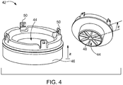
Fig. 4 , acomplementary connection element 42 of theventing device 10 is shown. The other embodiments of theventing device 10 are further shown inFig. 4 to 7 . - The
complementary connection element 42 comprises a complementaryfluid guiding portion 44 and asecond sealing element 46. Thecomplementary connection element 42 may also be an injection molded part. Thesecond sealing element 46 may be made of foam rubber that may be applied to thecomplementary connection element 42 in a second injection molding process or may be glued to thecomplementary connection element 42 as an additional sealing part. Further, thecomplementary connection element 42 comprises asecond filter element 48. Thesecond filter element 48 may be made of PA or PA66. It may be embodied by a strainer-type of filter element and may have a second mesh size of 950 mm2. Thus, larger objects can be prevented from entering the complementaryfluid guiding portion 44. - Now, exemplarily referring to
Fig. 4 and1 , it is highlighted that thefirst connection element 20 and thecomplementary connection element 42 are each comprising a number of latchingportions 50. As shown, thefirst connection element 20 may havemale latching portions 50 and thecomplementary connection element 42 may havefemale latching portions 50. By bringing the latchingportions 50 of the firstcomplementary connection element 42 and thefirst connection element 20 into engagement, an assembly as described inFig. 5 to 7 can be obtained, which will be discussed in more detail later. - In the illustrated examples the
first connection element 20 and thecomplementary connection element 42 are each comprising four latchingportions 50. The latchingportions 50 are uniformly distributed over an outer contour of thecomplementary connection element 42 and thefirst connection element 20, respectively. - Now referring to
Fig. 5 , another embodiment of theventing device 10 is shown, which is based on the embodiment ofFig. 1 along with thecomplementary connection element 42 shown inFig. 4 , so that only the differences regarding the embodiments of the venting device shown inFig. 1 is highlighted herein. - As can be seen, the
complementary connection element 42 and thefirst connection element 20 are releasably connected by a latching mechanism formed by the latchingportions 50. Thecomplementary connection element 42 is connected to thefirst connection element 20 from theside 38 of thefirst sealing element 26 that is averted from thefirst thread element 24. This way, the firstfluid guiding portion 22 is elongated by the complementaryfluid guiding portion 44. - If the
venting device 10 is connected to thebattery module housing 12, the ventingdevice 10 may fluidly connect thebattery module housing 12 with a secondary technical system 56 (seeFig. 8 ), wherein thesecond sealing element 46 functions as an interface safely sealing theventing device 10 against the secondarytechnical system 56. - Now turning to
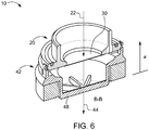
Fig. 6 , a cross sectional view of the embodiment of theventing device 10 ofFig. 5 is shown. Here, the firstfluid guiding portion 22 elongated by the complementaryfluid guiding portion 44 is shown in more detail, both forming an elongated common fluid guiding portion running through the first andsecond filter element first filter element 30 from objects coming from the environment, thesecond filter element 48 has a second mesh size, larger than the first mesh size of thefirst filter element 30. - Now referring to
Fig. 7 , another embodiment of theventing device 10 is shown, which is based on the embodiment ofFig. 2 along with thecomplementary connection element 42 shown inFig. 4 , so that only the difference regarding the embodiment of the venting device shown inFig. 5 shall highlighted herein, which is the use of thecomplementary thread element 32. - Now referring to
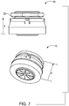
Fig. 8 , avehicle 52 with abattery system 54 and aventing device 10 according to an embodiment is shown. - The venting
device 10 is on the one hand connected to thewall 14 of thebattery module housing 12 by functional surface pairing of thefirst thread element 24 of theventing device 10 and the threadedconnection portion 16 of thebattery module housing 12. Further, thesecond sealing element 46 of thecomplementary connection element 42 of theventing device 10 is closely in contact with a secondarytechnical system 56 of thevehicle 52. The secondarytechnical system 56 is a chassis of thevehicle 52 in this example, but may be different in other embodiments. - The shown application of the
venting device 10 allows for drainage of fluid like gas from thebattery system 54 to the environment 58 of thevehicle 52 via the firstfluid guiding portion 22 and the complementaryfluid guiding portion 44.
Claims (13)
- Venting device (10) for a battery module housing (12), comprising at least:- a first connection element (20) with a first fluid guiding portion (22) and a first thread element (24) for connecting the venting device (10) with the battery module housing (12);- a first sealing element (26); and- a first filter element (30) arranged in the first fluid guiding portion (22);wherein the venting device (10) is adapted to be sealed against the battery module housing (12) by the first sealing element (26), if the first connection element (20) is screwed together with the battery module housing (12), and
wherein the venting device (10) further comprises a complementary connection element (42) that is releasably connectable to the first connection element (20) from a side (38) of the first sealing element (26) which is averted from the first thread element (24), with the complementary connection element (42) having a complementary fluid guiding portion (44) that elongates the first fluid guiding portion (22) of the first connection element (20), if connected thereto, and the complementary connection element (42) having a second sealing element (46) that is adapted to seal the venting device (10) against a secondary technical system (56) that is to be fluidly connected to the battery module housing (12). - Venting device (10) of claim 1, characterized in that the first filter element (30) has a first mesh size of 950 mm2 to 970 mm2.
- Venting device (10) of one of the preceding claims, characterized in that the first sealing element (26) and/or the first filter element (30) are forming a first composite component (18) with the first connection element (20).
- Venting device (10) of claim 1 or 2, characterized in that the first sealing element (26) and/or the first filter element (30) are forming a first injection molded component with the first connection element (20).
- Venting device (10) of one of the preceding claims, characterized in that the first connection element (20) comprises a collar (28) to which the first sealing element (26) is applied.
- Venting device (10) of one of the preceding claims, characterized in that the venting device (10) further comprises a complementary thread element (32) screwable to the first thread element (24) so as to allow for clamping of a wall (14) of the battery module housing (12) between the complementary thread element (32) and the first sealing element (26).
- Venting device (10) of claim 1, characterized in that the second sealing element (46) is made of foam rubber applied to the complementary connection element (42).
- Venting device (10) of claim 1 or 7, characterized in that the complementary connection element (42) and the first connection element (20) are connectable by a latching mechanism.
- Venting device (10) of claim 8, characterized in that the latching mechanism comprises at least three latching portions (50), uniformly distributed over an outer contour of the complementary connection element (42) and the first connection element (20), respectively.
- Venting device (10) of one of the claims 1 and 7 to 9, characterized in that the complementary connection element (42) comprises a second filter element (48) arranged in the complementary fluid guiding portion (44).
- Venting device (10) of claim 10, characterized in that the second filter element (48) has a second mesh size, larger than the first mesh size of the first filter element (30).
- Battery system (54), comprising a battery module housing (12) and a venting device (10) of one of the preceding claims, wherein the venting device (10) is connected to the battery module housing (12) by functional surface pairing of at least one thread element (24, 32) of the venting device (10) and the battery module housing (12).
- Vehicle (52), comprising a battery system (54) of claim 12, wherein a second sealing element (46) of a complementary connection element (42) of a venting device (10) of the battery system (54) is in contact with a secondary technical system (56) of the vehicle (52).
Priority Applications (4)
| Application Number | Priority Date | Filing Date | Title |
|---|---|---|---|
| HUE18154607A HUE055652T2 (en) | 2018-02-01 | 2018-02-01 | Venting device for a battery system |
| PL18154607T PL3522259T3 (en) | 2018-02-01 | 2018-02-01 | Venting device for a battery system |
| EP18154607.8A EP3522259B1 (en) | 2018-02-01 | 2018-02-01 | Venting device for a battery system |
| PCT/KR2018/014353 WO2019151627A1 (en) | 2018-02-01 | 2018-11-21 | Venting device for a battery system |
Applications Claiming Priority (1)
| Application Number | Priority Date | Filing Date | Title |
|---|---|---|---|
| EP18154607.8A EP3522259B1 (en) | 2018-02-01 | 2018-02-01 | Venting device for a battery system |
Publications (2)
| Publication Number | Publication Date |
|---|---|
| EP3522259A1 EP3522259A1 (en) | 2019-08-07 |
| EP3522259B1 true EP3522259B1 (en) | 2021-05-05 |
Family
ID=61132270
Family Applications (1)
| Application Number | Title | Priority Date | Filing Date |
|---|---|---|---|
| EP18154607.8A Active EP3522259B1 (en) | 2018-02-01 | 2018-02-01 | Venting device for a battery system |
Country Status (4)
| Country | Link |
|---|---|
| EP (1) | EP3522259B1 (en) |
| HU (1) | HUE055652T2 (en) |
| PL (1) | PL3522259T3 (en) |
| WO (1) | WO2019151627A1 (en) |
Families Citing this family (3)
| Publication number | Priority date | Publication date | Assignee | Title |
|---|---|---|---|---|
| FR3114194B1 (en) * | 2020-09-17 | 2022-12-02 | Psa Automobiles Sa | BATTERY BREATHING SYSTEM |
| FR3116657A1 (en) * | 2020-11-23 | 2022-05-27 | Commissariat A L'energie Atomique Et Aux Energies Alternatives | Metal-ion accumulator fitted with a degassing duct, Battery module or Battery pack associated with liquid cooling. |
| DE102024000057A1 (en) * | 2024-01-10 | 2025-07-10 | Mercedes-Benz Group AG | Pressure compensation device for an electrical energy storage device |
Family Cites Families (11)
| Publication number | Priority date | Publication date | Assignee | Title |
|---|---|---|---|---|
| BE554768A (en) * | 1956-11-27 | |||
| SU603024A1 (en) * | 1976-12-24 | 1978-04-15 | Предприятие П/Я Г-4036 | Ventilation cap for electric storage battery |
| JP4288824B2 (en) * | 2000-03-23 | 2009-07-01 | 新神戸電機株式会社 | Battery plug for storage battery |
| US7101640B1 (en) * | 2000-11-03 | 2006-09-05 | Exide Technologies | Screw-in vent plug for lead-acid batteries |
| US20020094473A1 (en) * | 2001-01-16 | 2002-07-18 | Ching-Yuan Lin | Venting casing for a battery |
| DE102005019296A1 (en) * | 2005-04-26 | 2006-11-09 | Deutsche Exide Gmbh | Degassing valve for acid batteries |
| CN202042536U (en) * | 2010-04-23 | 2011-11-16 | 比亚迪股份有限公司 | A battery explosion-proof structure and power battery |
| CN202308124U (en) * | 2011-10-28 | 2012-07-04 | 比亚迪股份有限公司 | Battery explosion-proof device and battery pack thereof |
| JP5880109B2 (en) | 2012-02-16 | 2016-03-08 | 日産自動車株式会社 | Battery pack explosion-proof valve |
| CN202817116U (en) * | 2012-09-05 | 2013-03-20 | 东莞市迈科锂离子电池工业节能技术研究院 | Improved lithium-ion power battery |
| CN206236731U (en) * | 2016-08-25 | 2017-06-09 | 浙江虹达特种橡胶制品有限公司 | For the strainer valve on battery |
-
2018
- 2018-02-01 EP EP18154607.8A patent/EP3522259B1/en active Active
- 2018-02-01 PL PL18154607T patent/PL3522259T3/en unknown
- 2018-02-01 HU HUE18154607A patent/HUE055652T2/en unknown
- 2018-11-21 WO PCT/KR2018/014353 patent/WO2019151627A1/en not_active Ceased
Also Published As
| Publication number | Publication date |
|---|---|
| PL3522259T3 (en) | 2021-11-02 |
| EP3522259A1 (en) | 2019-08-07 |
| WO2019151627A1 (en) | 2019-08-08 |
| HUE055652T2 (en) | 2021-12-28 |
Similar Documents
| Publication | Publication Date | Title |
|---|---|---|
| US9368773B2 (en) | Battery cell module, method for producing a battery cell module, battery and motor vehicle | |
| US20170331089A1 (en) | Power source device | |
| JP6549307B2 (en) | Cartridge for secondary battery and battery module including the same | |
| CN111180930B (en) | Vehicle connector | |
| EP2093819B1 (en) | Cell module | |
| US11962031B2 (en) | Ventilation device for battery and battery comprising the same | |
| EP2656431B1 (en) | Multi-cell battery module with integral cooling and assembly aids | |
| US11811085B2 (en) | Degassing unit and electronics housing, in particular battery housing | |
| US10944136B2 (en) | Battery cell, method for the production thereof and battery module | |
| JP7581630B2 (en) | Power storage device | |
| US20170025664A1 (en) | Battery module | |
| EP3522259A1 (en) | Venting device for a battery system | |
| US10797365B2 (en) | Battery module | |
| EP2424003A1 (en) | Vented battery pack | |
| CN115701781B (en) | End cap assembly, battery cell, battery, and apparatus and method for manufacturing battery cell | |
| CN117577966A (en) | Pressure equalization device for traction battery packs | |
| KR102490604B1 (en) | battery module assembly | |
| CN120019539A (en) | Power storage device | |
| JP7135852B2 (en) | power storage device | |
| CN110091707A (en) | The cooling structure of electrical storage device | |
| US20250279504A1 (en) | Heat exchange assembly, battery and electrical device | |
| US20200403200A1 (en) | Battery module | |
| CN223451112U (en) | Explosion-proof valves, battery covers, battery cells, battery packs and electrical devices | |
| CN108808164B (en) | Liquid cooling system and battery system | |
| JP2026502873A (en) | Battery module system, assembly, and manufacturing method |
Legal Events
| Date | Code | Title | Description |
|---|---|---|---|
| PUAI | Public reference made under article 153(3) epc to a published international application that has entered the european phase |
Free format text: ORIGINAL CODE: 0009012 |
|
| STAA | Information on the status of an ep patent application or granted ep patent |
Free format text: STATUS: REQUEST FOR EXAMINATION WAS MADE |
|
| 17P | Request for examination filed |
Effective date: 20190416 |
|
| AK | Designated contracting states |
Kind code of ref document: A1 Designated state(s): AL AT BE BG CH CY CZ DE DK EE ES FI FR GB GR HR HU IE IS IT LI LT LU LV MC MK MT NL NO PL PT RO RS SE SI SK SM TR |
|
| AX | Request for extension of the european patent |
Extension state: BA ME |
|
| REG | Reference to a national code |
Ref country code: DE Ref legal event code: R079 Ref document number: 602018016411 Country of ref document: DE Free format text: PREVIOUS MAIN CLASS: H01M0002120000 Ipc: H01M0050308000 |
|
| GRAP | Despatch of communication of intention to grant a patent |
Free format text: ORIGINAL CODE: EPIDOSNIGR1 |
|
| STAA | Information on the status of an ep patent application or granted ep patent |
Free format text: STATUS: GRANT OF PATENT IS INTENDED |
|
| RIC1 | Information provided on ipc code assigned before grant |
Ipc: H01M 50/308 20210101AFI20210203BHEP Ipc: H01M 50/30 20210101ALI20210203BHEP |
|
| INTG | Intention to grant announced |
Effective date: 20210215 |
|
| GRAS | Grant fee paid |
Free format text: ORIGINAL CODE: EPIDOSNIGR3 |
|
| GRAA | (expected) grant |
Free format text: ORIGINAL CODE: 0009210 |
|
| STAA | Information on the status of an ep patent application or granted ep patent |
Free format text: STATUS: THE PATENT HAS BEEN GRANTED |
|
| AK | Designated contracting states |
Kind code of ref document: B1 Designated state(s): AL AT BE BG CH CY CZ DE DK EE ES FI FR GB GR HR HU IE IS IT LI LT LU LV MC MK MT NL NO PL PT RO RS SE SI SK SM TR |
|
| REG | Reference to a national code |
Ref country code: GB Ref legal event code: FG4D |
|
| REG | Reference to a national code |
Ref country code: CH Ref legal event code: EP |
|
| REG | Reference to a national code |
Ref country code: AT Ref legal event code: REF Ref document number: 1390970 Country of ref document: AT Kind code of ref document: T Effective date: 20210515 |
|
| REG | Reference to a national code |
Ref country code: IE Ref legal event code: FG4D |
|
| REG | Reference to a national code |
Ref country code: DE Ref legal event code: R096 Ref document number: 602018016411 Country of ref document: DE |
|
| REG | Reference to a national code |
Ref country code: LT Ref legal event code: MG9D |
|
| PG25 | Lapsed in a contracting state [announced via postgrant information from national office to epo] |
Ref country code: FI Free format text: LAPSE BECAUSE OF FAILURE TO SUBMIT A TRANSLATION OF THE DESCRIPTION OR TO PAY THE FEE WITHIN THE PRESCRIBED TIME-LIMIT Effective date: 20210505 Ref country code: LT Free format text: LAPSE BECAUSE OF FAILURE TO SUBMIT A TRANSLATION OF THE DESCRIPTION OR TO PAY THE FEE WITHIN THE PRESCRIBED TIME-LIMIT Effective date: 20210505 Ref country code: HR Free format text: LAPSE BECAUSE OF FAILURE TO SUBMIT A TRANSLATION OF THE DESCRIPTION OR TO PAY THE FEE WITHIN THE PRESCRIBED TIME-LIMIT Effective date: 20210505 Ref country code: BG Free format text: LAPSE BECAUSE OF FAILURE TO SUBMIT A TRANSLATION OF THE DESCRIPTION OR TO PAY THE FEE WITHIN THE PRESCRIBED TIME-LIMIT Effective date: 20210805 |
|
| PG25 | Lapsed in a contracting state [announced via postgrant information from national office to epo] |
Ref country code: RS Free format text: LAPSE BECAUSE OF FAILURE TO SUBMIT A TRANSLATION OF THE DESCRIPTION OR TO PAY THE FEE WITHIN THE PRESCRIBED TIME-LIMIT Effective date: 20210505 Ref country code: SE Free format text: LAPSE BECAUSE OF FAILURE TO SUBMIT A TRANSLATION OF THE DESCRIPTION OR TO PAY THE FEE WITHIN THE PRESCRIBED TIME-LIMIT Effective date: 20210505 Ref country code: LV Free format text: LAPSE BECAUSE OF FAILURE TO SUBMIT A TRANSLATION OF THE DESCRIPTION OR TO PAY THE FEE WITHIN THE PRESCRIBED TIME-LIMIT Effective date: 20210505 Ref country code: NO Free format text: LAPSE BECAUSE OF FAILURE TO SUBMIT A TRANSLATION OF THE DESCRIPTION OR TO PAY THE FEE WITHIN THE PRESCRIBED TIME-LIMIT Effective date: 20210805 Ref country code: PT Free format text: LAPSE BECAUSE OF FAILURE TO SUBMIT A TRANSLATION OF THE DESCRIPTION OR TO PAY THE FEE WITHIN THE PRESCRIBED TIME-LIMIT Effective date: 20210906 Ref country code: IS Free format text: LAPSE BECAUSE OF FAILURE TO SUBMIT A TRANSLATION OF THE DESCRIPTION OR TO PAY THE FEE WITHIN THE PRESCRIBED TIME-LIMIT Effective date: 20210905 Ref country code: GR Free format text: LAPSE BECAUSE OF FAILURE TO SUBMIT A TRANSLATION OF THE DESCRIPTION OR TO PAY THE FEE WITHIN THE PRESCRIBED TIME-LIMIT Effective date: 20210806 |
|
| REG | Reference to a national code |
Ref country code: NL Ref legal event code: MP Effective date: 20210505 |
|
| REG | Reference to a national code |
Ref country code: HU Ref legal event code: AG4A Ref document number: E055652 Country of ref document: HU |
|
| PG25 | Lapsed in a contracting state [announced via postgrant information from national office to epo] |
Ref country code: NL Free format text: LAPSE BECAUSE OF FAILURE TO SUBMIT A TRANSLATION OF THE DESCRIPTION OR TO PAY THE FEE WITHIN THE PRESCRIBED TIME-LIMIT Effective date: 20210505 |
|
| PG25 | Lapsed in a contracting state [announced via postgrant information from national office to epo] |
Ref country code: RO Free format text: LAPSE BECAUSE OF FAILURE TO SUBMIT A TRANSLATION OF THE DESCRIPTION OR TO PAY THE FEE WITHIN THE PRESCRIBED TIME-LIMIT Effective date: 20210505 Ref country code: DK Free format text: LAPSE BECAUSE OF FAILURE TO SUBMIT A TRANSLATION OF THE DESCRIPTION OR TO PAY THE FEE WITHIN THE PRESCRIBED TIME-LIMIT Effective date: 20210505 Ref country code: CZ Free format text: LAPSE BECAUSE OF FAILURE TO SUBMIT A TRANSLATION OF THE DESCRIPTION OR TO PAY THE FEE WITHIN THE PRESCRIBED TIME-LIMIT Effective date: 20210505 Ref country code: SM Free format text: LAPSE BECAUSE OF FAILURE TO SUBMIT A TRANSLATION OF THE DESCRIPTION OR TO PAY THE FEE WITHIN THE PRESCRIBED TIME-LIMIT Effective date: 20210505 Ref country code: SK Free format text: LAPSE BECAUSE OF FAILURE TO SUBMIT A TRANSLATION OF THE DESCRIPTION OR TO PAY THE FEE WITHIN THE PRESCRIBED TIME-LIMIT Effective date: 20210505 Ref country code: EE Free format text: LAPSE BECAUSE OF FAILURE TO SUBMIT A TRANSLATION OF THE DESCRIPTION OR TO PAY THE FEE WITHIN THE PRESCRIBED TIME-LIMIT Effective date: 20210505 Ref country code: ES Free format text: LAPSE BECAUSE OF FAILURE TO SUBMIT A TRANSLATION OF THE DESCRIPTION OR TO PAY THE FEE WITHIN THE PRESCRIBED TIME-LIMIT Effective date: 20210505 |
|
| REG | Reference to a national code |
Ref country code: DE Ref legal event code: R097 Ref document number: 602018016411 Country of ref document: DE |
|
| PLBE | No opposition filed within time limit |
Free format text: ORIGINAL CODE: 0009261 |
|
| STAA | Information on the status of an ep patent application or granted ep patent |
Free format text: STATUS: NO OPPOSITION FILED WITHIN TIME LIMIT |
|
| 26N | No opposition filed |
Effective date: 20220208 |
|
| PG25 | Lapsed in a contracting state [announced via postgrant information from national office to epo] |
Ref country code: IS Free format text: LAPSE BECAUSE OF FAILURE TO SUBMIT A TRANSLATION OF THE DESCRIPTION OR TO PAY THE FEE WITHIN THE PRESCRIBED TIME-LIMIT Effective date: 20210905 Ref country code: AL Free format text: LAPSE BECAUSE OF FAILURE TO SUBMIT A TRANSLATION OF THE DESCRIPTION OR TO PAY THE FEE WITHIN THE PRESCRIBED TIME-LIMIT Effective date: 20210505 |
|
| PG25 | Lapsed in a contracting state [announced via postgrant information from national office to epo] |
Ref country code: IT Free format text: LAPSE BECAUSE OF FAILURE TO SUBMIT A TRANSLATION OF THE DESCRIPTION OR TO PAY THE FEE WITHIN THE PRESCRIBED TIME-LIMIT Effective date: 20210505 |
|
| PG25 | Lapsed in a contracting state [announced via postgrant information from national office to epo] |
Ref country code: MC Free format text: LAPSE BECAUSE OF FAILURE TO SUBMIT A TRANSLATION OF THE DESCRIPTION OR TO PAY THE FEE WITHIN THE PRESCRIBED TIME-LIMIT Effective date: 20210505 |
|
| REG | Reference to a national code |
Ref country code: CH Ref legal event code: PL |
|
| REG | Reference to a national code |
Ref country code: BE Ref legal event code: MM Effective date: 20220228 |
|
| PG25 | Lapsed in a contracting state [announced via postgrant information from national office to epo] |
Ref country code: LU Free format text: LAPSE BECAUSE OF NON-PAYMENT OF DUE FEES Effective date: 20220201 |
|
| PG25 | Lapsed in a contracting state [announced via postgrant information from national office to epo] |
Ref country code: LI Free format text: LAPSE BECAUSE OF NON-PAYMENT OF DUE FEES Effective date: 20220228 Ref country code: IE Free format text: LAPSE BECAUSE OF NON-PAYMENT OF DUE FEES Effective date: 20220201 Ref country code: CH Free format text: LAPSE BECAUSE OF NON-PAYMENT OF DUE FEES Effective date: 20220228 |
|
| PG25 | Lapsed in a contracting state [announced via postgrant information from national office to epo] |
Ref country code: BE Free format text: LAPSE BECAUSE OF NON-PAYMENT OF DUE FEES Effective date: 20220228 |
|
| P01 | Opt-out of the competence of the unified patent court (upc) registered |
Effective date: 20230528 |
|
| REG | Reference to a national code |
Ref country code: AT Ref legal event code: UEP Ref document number: 1390970 Country of ref document: AT Kind code of ref document: T Effective date: 20210505 |
|
| PG25 | Lapsed in a contracting state [announced via postgrant information from national office to epo] |
Ref country code: MK Free format text: LAPSE BECAUSE OF FAILURE TO SUBMIT A TRANSLATION OF THE DESCRIPTION OR TO PAY THE FEE WITHIN THE PRESCRIBED TIME-LIMIT Effective date: 20210505 Ref country code: CY Free format text: LAPSE BECAUSE OF FAILURE TO SUBMIT A TRANSLATION OF THE DESCRIPTION OR TO PAY THE FEE WITHIN THE PRESCRIBED TIME-LIMIT Effective date: 20210505 |
|
| PG25 | Lapsed in a contracting state [announced via postgrant information from national office to epo] |
Ref country code: TR Free format text: LAPSE BECAUSE OF FAILURE TO SUBMIT A TRANSLATION OF THE DESCRIPTION OR TO PAY THE FEE WITHIN THE PRESCRIBED TIME-LIMIT Effective date: 20210505 |
|
| PG25 | Lapsed in a contracting state [announced via postgrant information from national office to epo] |
Ref country code: MT Free format text: LAPSE BECAUSE OF FAILURE TO SUBMIT A TRANSLATION OF THE DESCRIPTION OR TO PAY THE FEE WITHIN THE PRESCRIBED TIME-LIMIT Effective date: 20210505 |
|
| PGFP | Annual fee paid to national office [announced via postgrant information from national office to epo] |
Ref country code: HU Payment date: 20260213 Year of fee payment: 9 |
|
| PGFP | Annual fee paid to national office [announced via postgrant information from national office to epo] |
Ref country code: GB Payment date: 20260128 Year of fee payment: 9 |
|
| PGFP | Annual fee paid to national office [announced via postgrant information from national office to epo] |
Ref country code: DE Payment date: 20260128 Year of fee payment: 9 |
|
| PGFP | Annual fee paid to national office [announced via postgrant information from national office to epo] |
Ref country code: AT Payment date: 20260127 Year of fee payment: 9 |
|
| PGFP | Annual fee paid to national office [announced via postgrant information from national office to epo] |
Ref country code: FR Payment date: 20260121 Year of fee payment: 9 |
|
| PGFP | Annual fee paid to national office [announced via postgrant information from national office to epo] |
Ref country code: PL Payment date: 20260128 Year of fee payment: 9 |