EP3522249A1 - Unit cell, and assembly comprising unit cell and spacer - Google Patents
Unit cell, and assembly comprising unit cell and spacer Download PDFInfo
- Publication number
- EP3522249A1 EP3522249A1 EP17852791.7A EP17852791A EP3522249A1 EP 3522249 A1 EP3522249 A1 EP 3522249A1 EP 17852791 A EP17852791 A EP 17852791A EP 3522249 A1 EP3522249 A1 EP 3522249A1
- Authority
- EP
- European Patent Office
- Prior art keywords
- unit cell
- spacer
- metal layer
- assembly
- cell
- Prior art date
- Legal status (The legal status is an assumption and is not a legal conclusion. Google has not performed a legal analysis and makes no representation as to the accuracy of the status listed.)
- Granted
Links
Images


Classifications
-
- H—ELECTRICITY
- H01—ELECTRIC ELEMENTS
- H01M—PROCESSES OR MEANS, e.g. BATTERIES, FOR THE DIRECT CONVERSION OF CHEMICAL ENERGY INTO ELECTRICAL ENERGY
- H01M50/00—Constructional details or processes of manufacture of the non-active parts of electrochemical cells other than fuel cells, e.g. hybrid cells
- H01M50/10—Primary casings; Jackets or wrappings
- H01M50/116—Primary casings; Jackets or wrappings characterised by the material
- H01M50/124—Primary casings; Jackets or wrappings characterised by the material having a layered structure
-
- H—ELECTRICITY
- H01—ELECTRIC ELEMENTS
- H01M—PROCESSES OR MEANS, e.g. BATTERIES, FOR THE DIRECT CONVERSION OF CHEMICAL ENERGY INTO ELECTRICAL ENERGY
- H01M50/00—Constructional details or processes of manufacture of the non-active parts of electrochemical cells other than fuel cells, e.g. hybrid cells
- H01M50/10—Primary casings; Jackets or wrappings
- H01M50/102—Primary casings; Jackets or wrappings characterised by their shape or physical structure
- H01M50/105—Pouches or flexible bags
-
- H—ELECTRICITY
- H01—ELECTRIC ELEMENTS
- H01M—PROCESSES OR MEANS, e.g. BATTERIES, FOR THE DIRECT CONVERSION OF CHEMICAL ENERGY INTO ELECTRICAL ENERGY
- H01M50/00—Constructional details or processes of manufacture of the non-active parts of electrochemical cells other than fuel cells, e.g. hybrid cells
- H01M50/10—Primary casings; Jackets or wrappings
- H01M50/116—Primary casings; Jackets or wrappings characterised by the material
- H01M50/117—Inorganic material
- H01M50/119—Metals
-
- H—ELECTRICITY
- H01—ELECTRIC ELEMENTS
- H01M—PROCESSES OR MEANS, e.g. BATTERIES, FOR THE DIRECT CONVERSION OF CHEMICAL ENERGY INTO ELECTRICAL ENERGY
- H01M50/00—Constructional details or processes of manufacture of the non-active parts of electrochemical cells other than fuel cells, e.g. hybrid cells
- H01M50/10—Primary casings; Jackets or wrappings
- H01M50/116—Primary casings; Jackets or wrappings characterised by the material
- H01M50/121—Organic material
-
- H—ELECTRICITY
- H01—ELECTRIC ELEMENTS
- H01M—PROCESSES OR MEANS, e.g. BATTERIES, FOR THE DIRECT CONVERSION OF CHEMICAL ENERGY INTO ELECTRICAL ENERGY
- H01M50/00—Constructional details or processes of manufacture of the non-active parts of electrochemical cells other than fuel cells, e.g. hybrid cells
- H01M50/10—Primary casings; Jackets or wrappings
- H01M50/116—Primary casings; Jackets or wrappings characterised by the material
- H01M50/124—Primary casings; Jackets or wrappings characterised by the material having a layered structure
- H01M50/126—Primary casings; Jackets or wrappings characterised by the material having a layered structure comprising three or more layers
- H01M50/129—Primary casings; Jackets or wrappings characterised by the material having a layered structure comprising three or more layers with two or more layers of only organic material
-
- H—ELECTRICITY
- H01—ELECTRIC ELEMENTS
- H01M—PROCESSES OR MEANS, e.g. BATTERIES, FOR THE DIRECT CONVERSION OF CHEMICAL ENERGY INTO ELECTRICAL ENERGY
- H01M50/00—Constructional details or processes of manufacture of the non-active parts of electrochemical cells other than fuel cells, e.g. hybrid cells
- H01M50/20—Mountings; Secondary casings or frames; Racks, modules or packs; Suspension devices; Shock absorbers; Transport or carrying devices; Holders
- H01M50/204—Racks, modules or packs for multiple batteries or multiple cells
- H01M50/207—Racks, modules or packs for multiple batteries or multiple cells characterised by their shape
- H01M50/211—Racks, modules or packs for multiple batteries or multiple cells characterised by their shape adapted for pouch cells
-
- H—ELECTRICITY
- H01—ELECTRIC ELEMENTS
- H01M—PROCESSES OR MEANS, e.g. BATTERIES, FOR THE DIRECT CONVERSION OF CHEMICAL ENERGY INTO ELECTRICAL ENERGY
- H01M50/00—Constructional details or processes of manufacture of the non-active parts of electrochemical cells other than fuel cells, e.g. hybrid cells
- H01M50/20—Mountings; Secondary casings or frames; Racks, modules or packs; Suspension devices; Shock absorbers; Transport or carrying devices; Holders
- H01M50/289—Mountings; Secondary casings or frames; Racks, modules or packs; Suspension devices; Shock absorbers; Transport or carrying devices; Holders characterised by spacing elements or positioning means within frames, racks or packs
- H01M50/291—Mountings; Secondary casings or frames; Racks, modules or packs; Suspension devices; Shock absorbers; Transport or carrying devices; Holders characterised by spacing elements or positioning means within frames, racks or packs characterised by their shape
-
- H—ELECTRICITY
- H01—ELECTRIC ELEMENTS
- H01M—PROCESSES OR MEANS, e.g. BATTERIES, FOR THE DIRECT CONVERSION OF CHEMICAL ENERGY INTO ELECTRICAL ENERGY
- H01M50/00—Constructional details or processes of manufacture of the non-active parts of electrochemical cells other than fuel cells, e.g. hybrid cells
- H01M50/50—Current conducting connections for cells or batteries
- H01M50/543—Terminals
- H01M50/547—Terminals characterised by the disposition of the terminals on the cells
- H01M50/55—Terminals characterised by the disposition of the terminals on the cells on the same side of the cell
-
- H—ELECTRICITY
- H01—ELECTRIC ELEMENTS
- H01M—PROCESSES OR MEANS, e.g. BATTERIES, FOR THE DIRECT CONVERSION OF CHEMICAL ENERGY INTO ELECTRICAL ENERGY
- H01M50/00—Constructional details or processes of manufacture of the non-active parts of electrochemical cells other than fuel cells, e.g. hybrid cells
- H01M50/50—Current conducting connections for cells or batteries
- H01M50/543—Terminals
- H01M50/552—Terminals characterised by their shape
- H01M50/553—Terminals adapted for prismatic, pouch or rectangular cells
- H01M50/557—Plate-shaped terminals
-
- H—ELECTRICITY
- H01—ELECTRIC ELEMENTS
- H01M—PROCESSES OR MEANS, e.g. BATTERIES, FOR THE DIRECT CONVERSION OF CHEMICAL ENERGY INTO ELECTRICAL ENERGY
- H01M2220/00—Batteries for particular applications
- H01M2220/20—Batteries in motive systems, e.g. vehicle, ship, plane
-
- H—ELECTRICITY
- H01—ELECTRIC ELEMENTS
- H01M—PROCESSES OR MEANS, e.g. BATTERIES, FOR THE DIRECT CONVERSION OF CHEMICAL ENERGY INTO ELECTRICAL ENERGY
- H01M50/00—Constructional details or processes of manufacture of the non-active parts of electrochemical cells other than fuel cells, e.g. hybrid cells
- H01M50/20—Mountings; Secondary casings or frames; Racks, modules or packs; Suspension devices; Shock absorbers; Transport or carrying devices; Holders
- H01M50/233—Mountings; Secondary casings or frames; Racks, modules or packs; Suspension devices; Shock absorbers; Transport or carrying devices; Holders characterised by physical properties of casings or racks, e.g. dimensions
- H01M50/24—Mountings; Secondary casings or frames; Racks, modules or packs; Suspension devices; Shock absorbers; Transport or carrying devices; Holders characterised by physical properties of casings or racks, e.g. dimensions adapted for protecting batteries from their environment, e.g. from corrosion
-
- H—ELECTRICITY
- H01—ELECTRIC ELEMENTS
- H01M—PROCESSES OR MEANS, e.g. BATTERIES, FOR THE DIRECT CONVERSION OF CHEMICAL ENERGY INTO ELECTRICAL ENERGY
- H01M50/00—Constructional details or processes of manufacture of the non-active parts of electrochemical cells other than fuel cells, e.g. hybrid cells
- H01M50/50—Current conducting connections for cells or batteries
- H01M50/502—Interconnectors for connecting terminals of adjacent batteries; Interconnectors for connecting cells outside a battery casing
- H01M50/503—Interconnectors for connecting terminals of adjacent batteries; Interconnectors for connecting cells outside a battery casing characterised by the shape of the interconnectors
-
- H—ELECTRICITY
- H01—ELECTRIC ELEMENTS
- H01M—PROCESSES OR MEANS, e.g. BATTERIES, FOR THE DIRECT CONVERSION OF CHEMICAL ENERGY INTO ELECTRICAL ENERGY
- H01M50/00—Constructional details or processes of manufacture of the non-active parts of electrochemical cells other than fuel cells, e.g. hybrid cells
- H01M50/50—Current conducting connections for cells or batteries
- H01M50/502—Interconnectors for connecting terminals of adjacent batteries; Interconnectors for connecting cells outside a battery casing
- H01M50/507—Interconnectors for connecting terminals of adjacent batteries; Interconnectors for connecting cells outside a battery casing comprising an arrangement of two or more busbars within a container structure, e.g. busbar modules
-
- Y—GENERAL TAGGING OF NEW TECHNOLOGICAL DEVELOPMENTS; GENERAL TAGGING OF CROSS-SECTIONAL TECHNOLOGIES SPANNING OVER SEVERAL SECTIONS OF THE IPC; TECHNICAL SUBJECTS COVERED BY FORMER USPC CROSS-REFERENCE ART COLLECTIONS [XRACs] AND DIGESTS
- Y02—TECHNOLOGIES OR APPLICATIONS FOR MITIGATION OR ADAPTATION AGAINST CLIMATE CHANGE
- Y02E—REDUCTION OF GREENHOUSE GAS [GHG] EMISSIONS, RELATED TO ENERGY GENERATION, TRANSMISSION OR DISTRIBUTION
- Y02E60/00—Enabling technologies; Technologies with a potential or indirect contribution to GHG emissions mitigation
- Y02E60/10—Energy storage using batteries
Definitions
- the present invention relates to a unit cell and to an assembly of a unit cell and a spacer.
- a unit cell nonaqueous secondary battery obtained by sandwiching a sealing a cell body (battery element) between a pair of sealing members (exterior film).
- the sealing member is formed by covering a sheet-shaped metal layer (moisture-proof layer) with a sheet-shaped insulating layer (synthetic resin layer).
- the outer edges (peripheral edge portions) of the pair of sealing members are folded and overlapped (refer to Patent Document 1.).
- An object of the present invention is to provide a unit cell, and an assembly of a unit cell and a spacer, which can be reduced in size while suppressing electrical leakage caused by condensation, even when a sealing member is used in which an end portion of a metal layer is exposed.
- a unit cell according to the present invention which achieves the object above comprises a cell body, an electrode tab, and a sealing member.
- the cell body includes a power-generating element and is formed into a flat shape.
- the electrode tab is extends out from the cell body.
- the sealing member includes a sheet-shaped metal layer and a sheet-shaped insulating layer that covers and insulates the metal layer from both sides, and sandwiches and seals the cell body. In the sealing member an exposed end portion of the metal layer is spaced from the surface of the insulating layer, while at least a portion of the outer edge that extends from the cell body is bent.
- An assembly of a unit cell and a spacer according to the present invention which achieves the object described above includes the above-described unit cell, and a spacer that supports the unit cell.
- the spacer has a housing portion that houses at least an exposed portion of the end portion of the metal layer.
- the orientation of a battery pack 100 is shown using arrows indicated by X, Y, and Z in each of the drawings.
- the direction of the arrow indicated by X is the longitudinal direction of the battery pack 100.
- the direction of the arrow indicated by Y is the transverse direction of the battery pack 100.
- the direction of the arrow indicated by Z is the stacking direction of the battery pack 100.
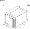
- Figure 1 is a perspective view illustrating the battery pack 100 according to an embodiment.
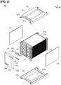
- Figure 2 is a perspective view illustrating a state in which a portion of a bus bar unit 130 (a protective cover 135, an anode side terminal 133, and a cathode side terminal 134) as well as a pressurizing unit 120 (an upper pressure plate 121, a lower pressure plate 122, and left and right side plates 123) are removed from the battery pack 100 shown in Figure 1 .
- Figure 3A is a perspective view illustrating a cross section of a main part of a state in which a bus bar 132 is joined to electrode tabs 112 of stacked unit cells 110.
- Figure 3B is an end surface view illustrating Figure 3A from the side.
- Figure 4 is a perspective view illustrating a state in which a bus bar holder 131 and the bus bars 132 are removed from a stacked body 110S illustrated in Figure 2 .
- Figure 5 is a perspective view illustrating a state in which a first cell sub-assembly 110M and a second cell sub-assembly 110N shown in Figure 4 are electrically connected by means of the bus bars 132.
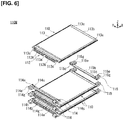
- Figure 6 is a perspective view illustrating a state in which the first cell sub-assembly 110M (three sets of unit cells 110 that are connected in parallel) shown in Figure 4 is disassembled for each unit cell 110, and a first spacer 114 and a second spacer 115 are removed from one (the uppermost) unit cell 110 thereof.
- Figure 7 is a perspective view illustrating a portion of an assembly 100A (unit cell 110 and first spacer 114).
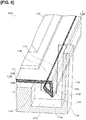
- Figure 8 is a perspective view illustrating a main part of the assembly 100A of Figure 7 .
- the unit cell 110 generally comprises a cell body 110H, an electrode tab 112 (corresponding to an anode side electrode tab 112A and a cathode side electrode tab 112K), and a sealing member (corresponding to a laminate film 113).
- the cell body 110H includes a power-generating element 111 and is formed into a flat shape.
- the anode side electrode tab 112A and the cathode side electrode tab 112K extend out from the cell body 110H.
- a pair of the laminate films 113 includes a sheet-shaped metal layer 113M, and a sheet-shaped insulating layer 113N that covers and insulates the metal layer 113M from both sides, and sandwiches and seals the cell body 110H.
- the pair of laminate films 113 has at least a portion of the outer edge 113d that extends from the cell body 110H being bent, and an exposed end portion 113e of the metal layer 113M is spaced from the surface 113f of the insulating layer 113N.
- the battery pack 100 generally comprises the above-described unit cell 110, and spacers (corresponding to a first spacer 114 and a second spacer 115) that support the unit cell 110.
- the first spacer 114 and the second spacer 115 have, for example, a housing portion 114j that has an insulating property, which houses at least a portion of the exposed end portion 113e of the metal layer 113M.
- a plurality of the battery packs 100 which include the assembly 100A of the unit cell 110 and the spacers (first spacer 114 and second spacer 115), are mounted in a vehicle such as an electric vehicle and are used as a power source for driving a vehicle motor.
- the battery pack 100 is configured by electrically connecting a stacked body 110S, obtained by stacking a plurality of the unit cells 110 by means of a bus bar unit 130, in a state of pressurization by a pressurizing unit 120.
- Each configuration of the battery pack 100 including the assembly 100A of the unit cell 110 and the spacers (first spacer 114 and second spacer 115), will be described below.
- the stacked body 110S is configured by alternately connecting in series the first cell sub-assembly 110M, which includes three of the unit cells 110 that are electrically connected in parallel, and the second cell sub-assembly 110N, which includes three of the unit cells 110 that are electrically connected in parallel.
- the first cell sub-assembly 110M corresponds to the three unit cells 110 that are positioned in the first row (lowermost row), the third row, the fifth row, and the seventh row (uppermost row) of the battery pack 100.
- the second cell sub-assembly 110N corresponds to the three unit cells 110 that are positioned in the second row, the fourth row, and the sixth row of the battery pack 100.
- the first cell sub-assembly 110M and the second cell sub-assembly 110N are similarly configured. However, the first cell sub-assembly 110M and the second cell sub-assembly 110N are arranged such that three anode side electrode tabs 112A and three cathode side electrode tabs 112K are alternately positioned along the Z direction, by interchanging the tops and bottoms of the three unit cells 110, as illustrated in Figures 4 and 5 .
- all of the anode side electrode tabs 112A are positioned on the right side in the drawing, and all of the cathode side electrode tabs 112K are positioned on the left side in the drawing, as illustrated in Figures 4 and 5 .
- the unit cell 110 corresponds to a lithium-ion secondary battery, for example.
- a plurality of the unit cells 110 are connected in series in order to satisfy the drive voltage specification of the vehicle motor.
- a plurality of the unit cells 110 are connected in parallel in order to ensure the battery capacity and to extend the travel distance of the vehicle.
- the unit cell 110 includes a cell body 110H, which includes a power-generating element 111 and is formed into a flat shape, an electrode tab 112 for exposing the power-generating element 111 to the outside, and a laminate film 113 for sealing the power-generating element 111, as illustrated in Figures 3A and 3B .
- the power-generating element 111 is charged with electric power from an outdoor charging station, or the like, and supplies driving power to the vehicle motor, or the like, by discharging the electric power.
- the power-generating element 111 is formed by stacking a plurality of sets of anodes and cathodes that are separated by separators.
- the electrode tab 112 is for exposing the power-generating element 111 to the outside, as illustrated in Figures 3A, 3B , and 4 .
- the electrode tab 112 includes the anode side electrode tab 112A and the cathode side electrode tab 112K.
- the proximal end side of the anode side electrode tab 112A is joined to all of the anodes included in one of the power-generating element 111.
- the anode side electrode tab 112A has the form of a thin plate and is made of aluminum in accordance with the characteristics of the anode.
- the proximal end side of the cathode side electrode tab 112K is joined to all of the cathodes included in one of the power-generating element 111.
- the cathode side electrode tab 112K has the form of a thin plate and is made of copper in accordance with the characteristics of the cathode.
- the electrode tab 112 is L-shaped from a proximal end portion 112c adjacent to the power-generating element 111 to the distal end portion 112d, as illustrated in Figure 3B .
- the distal end portion 112d of the electrode tab 112 is bent downward in the Z direction.
- the shape of the distal end portion 112d of the electrode tab 112 is not limited to the form of an L.
- the electrode tab 112 may be U-shaped by further extending the distal end portion 112d and by folding back the extended portion toward the power-generating element 111.
- the proximal end portion 112c of the electrode tab 112 may have an undulating or curved form.
- the distal end portion 112d of the electrode tab 112 makes surface contact with the bus bar 132.
- the laminate film 113 is configured in pairs and is for sealing the cell body 110H from above and below along the Z direction, as illustrated in Figures 3A and 3B .
- the anode side electrode tab 112A and the cathode side electrode tab 112K extend out to the outside from gaps between one end portions 113a thereof along the Y direction.
- the laminate film 113 includes a sheet-shaped metal layer 113M and a sheet-shaped insulating layer 113N that covers and insulates the metal layer 113M from both sides, as illustrated in Figure 8 .
- the outer edges 113d of the pair of laminate films 113 that extend from the cell body 110H on both sides of the unit cell 110 along the X direction have two bends, as illustrated in Figures 7 and 8 .
- the outer edges 113d have a total of two bends: one bend downward in the Z direction, which is the stacking direction of the unit cells 110; and another bend protruding upwards.
- the bent portion of the outer edge 113d is inclined with respect to the Z direction, such that the exposed end portion 113e of the metal layer 113M faces the cell body 110H.
- the exposed end portion 113e of the metal layer 113M is spaced from the surface 113f of the insulating layer 113N, as illustrated in Figure 8 .
- the unit cells 110 are stacked, as illustrated in Figures 3 and 4 , in a state of support by means of a pair of spacers (first spacer 114 and second spacer 115), as illustrated in Figure 6 .
- the pair of spacers (first spacer 114 and second spacer 115) are used to arrange the unit cells 110 at constant intervals along the Z direction, as illustrated in Figures 2 , 3A, and 3B .
- the first spacer 114 supports the unit cell 110 on the side provided with the electrode tab 112.
- the second spacer 115 supports the unit cell 110 on the side not provided with the electrode tab 112, so as to oppose the first spacer 114 in the X direction of the unit cell 110.
- the first spacer 114 has the form of an elongated plate having recesses and protrusions, as illustrated in Figure 6 , and is made from reinforced plastic having an insulating property.
- the first spacer 114 is provided so as to oppose the one end portions 113a of the pair of laminate films 113.
- the first spacer 114 supports the one end portion 113a of the laminate film 113 by means of a flat supporting surface 114b, as illustrated in Figures 3 and 6 .
- the first spacer 114 has an abutting surface 114h on a wall surface along the Z direction adjacent to the supporting surface 114b.
- the abutting surface 114h positions the distal end portion 112d of the electrode tab 112 along the X direction, as illustrated in Figure 3B .
- the first spacer 114 has a pair of connecting pins 114c that respectively protrude upward at both ends of the supporting surface 114b along the Y direction, as illustrated in Figure 6 .
- the pair of connecting pins 114c are cylindrical in form and are inserted into connecting holes 113c that are formed at both ends of the end portion 113a of the laminate film 113 along the Y direction, thereby positioning the unit cell 110.
- first spacers 114 In a plurality of the first spacers 114, an upper surface 114a of one first spacer 114 and a lower surface 114d of another first spacer 114 are in contact, as illustrated in Figure 3B .
- the plurality of first spacers 114 are positioned relative to each other by fitting a cylindrical positioning pin 114e that protrudes from the upper surface 114a of one first spacer 114 being fitted into a positioning hole 114f that opens onto the lower surface 114d of another first spacer 114, as illustrated in Figure 3B .
- the first spacer 114 is provided with locating holes 114g at both ends along the Y direction, as illustrated in Figure 6 . Bolts for connecting and positioning a plurality of the battery packs 100 relative to each other along the Z direction are inserted in the locating holes 114g.
- first spacer 114 and the second spacer 115 have, for example, a housing portion 114j with an insulating property, which houses a portion of the exposed end portion 113e of the metal layer 113M, as illustrated in Figures 7 and 8 .
- the housing portion 114j has the form of a recessed hole that is formed by cutting off a portion of an upper surface 114a of the first spacer 114 and a portion of the supporting surface 114b adjacent to said upper surface 114a, from the upper side to the lower side, and that has a rectangular bottom surface 114p.
- the housing portion 114j has a first protrusion 114r that protrudes in a protruding shape from the bottom surface 114p upward in a stepped manner, as illustrated in Figures 7 and 8 .
- the first protrusion 114r constitutes a portion of a stepped side wall in the concave housing portion 114j along the Y direction of the unit cell 110.
- the first protrusion 114r comes into contact with the bent outer edge 113d of the laminate film 113 from below to restrict the position of the outer edge 113d. That is, the first protrusion 114r functions as a restricting portion that forcibly separates the exposed end portion 113e of the metal layer 113M so as to float from the bottom surface 114p of the housing portion 114j.
- the first protrusion 114r restricts the angle of the outer edge 113d such that the exposed end portion 113e of the metal layer 113M does not come into contact with the side wall 114t of the unit cell 110 that is adjacent along the Y direction. That is, the first protrusion 114r functions as a restricting portion that separates the exposed end portion 113e of the metal layer 113M from the side wall 114t of the housing portion 114j.
- the housing portion 114j has a second protrusion 114s that protrudes in a protruding shape from an inner-side surface 114q thereof inward, as illustrated in Figures 7 and 8 .
- the second protrusion 114s constitutes a portion of a side wall in the concave housing portion 114j along the Y direction of the unit cell 110.
- the second protrusion 114s comes into contact with the bent outer edge 113d of the laminate film 113 from the side to restrict the position of the outer edge 113d. That is, second protrusion 114s functions as a restricting portion that forcibly separates the exposed end portion 113e of the metal layer 113M from the inner-side surface 114q of the housing portion 114j.
- the second spacer 115 is configured by simplifying the first spacer 114. Similar to the first spacer 114, as shown in Figure 6 , the second spacer 115 includes a supporting surface 115b for supporting the other end portion 113b of the laminate film 113, positioning pins 114e for positioning the second spacers with respect to each other, connecting pins 115c for positioning the unit cell 110, and locating holes 115g into which are inserted bolts for connecting and positioning a plurality of the battery packs 100 with respect to each other.
- the second spacer 115 has, for example, a housing portion with an insulating property, which houses the exposed end portion 113e of the metal layer 113M, a protruding first protrusion that protrudes from the bottom surface of the housing portion, a protruding second protrusion that protrudes from the inner-side surface of the housing portion, etc.
- the configuration of the pressurizing unit 120 will be described in detail.
- the pressurizing unit 120 includes the upper pressure plate 121 and the lower pressure plate 122, which pressurize the power-generating element 111 of each of the unit cells 110 of the stacked body 110S from above and below, and a pair of side plates 123 that fix the upper pressure plate 121 and the lower pressure plate 122 in a state of pressurization of the stacked body 110S.
- the upper pressure plate 121 together with the lower pressure plate 122, hold and sandwich the plurality of the unit cells 110 that constitute the stacked body 110S from above and below and pressurize the power-generating element 111 of each of the unit cells 110, as illustrated in Figures 1 and 2 .
- the upper pressure plate 121 has the form of a plate with recesses and protrusions and is made from a metal possessing sufficient rigidity.
- the upper pressure plate 121 is provided on a horizontal plane.
- the upper pressure plate 121 has a pressurizing surface 121a that pressurizes the power-generating element 111 downwards, as illustrated in Figure 2 .
- the pressurizing surface 121a is formed flat, protruding downward from a central portion of the upper pressure plate 121.
- the upper pressure plate 121 has locating holes 121b, into which bolts for interconnecting the battery packs 100 are inserted.
- the locating holes 121b are through-holes formed at the four corners of the upper pressure plate 121.
- the lower pressure plate 122 has the same shape as the upper pressure plate 121, and is provided so that the top and bottom of the upper pressure plate 121 can be inverted, as illustrated in Figure 2 .
- the lower pressure plate 122 includes a pressurizing surface 122a that pressurizes the power-generating element 111 upwards, and locating holes 122b, into which for connecting and positioning the battery packs 100 relative to each other along the Z direction are inserted bolts.
- the pair of side plates 123 are for fixing the upper pressure plate 121 and the lower pressure plate 122 in a state of pressurization of the stacked body 110S, as illustrated in Figures 1 and 2 . That is, the pair of side plates 123 hold the interval between the upper pressure plate 121 and the lower pressure plate 122 constant. In addition, the pair of side plates 123 cover and protect the side surfaces of the stacked unit cells 110 along the X direction.
- the side plate 123 has the form of a flat plate and is made of metal.
- the pair of side plates 123 stand upright so as to face both side surfaces of the stacked unit cells 110 along the X direction.
- the pair of side plates 123 are welded to the upper pressure plate 121 and the lower pressure plate 122.
- bus bar unit 130 The configuration of the bus bar unit 130 will be described in detail.
- the bus bar unit 130 includes a bus bar holder 131 that integrally holds a plurality of the bus bars 132, the bus bars 132 that electrically interconnect the vertically adjacent electrode tabs 112 of the unit cells 110, an anode side terminal 133 that causes the anode side terminal ends of the plurality of the electrically connected unit cells 110 to oppose an external input/output terminal, a cathode side terminal 134 that causes the cathode side terminal ends of the plurality of the electrically connected unit cells 110 to oppose an external input/output terminal, and a protective cover 135 for protecting the bus bars 132, and the like.
- the bus bar holder 131 is for integrally holding a plurality of the bus bars 132, as illustrated in Figures 2 and 4 .
- the bus bar holder 131 integrally holds the plurality of the bus bars 132 in a matrix so as to oppose the electrode tab 112 of each of the unit cells 110 of the stacked body 110S.
- the bus bar holder 131 is made of resin having insulating properties, and has the form of a frame.
- the bus bar holder 131 is respectively provided with a pair of columnar support portions 131a that stand upright along the Z direction, so as to be positioned on both sides of the longitudinal direction of the first spacers 114 that support the electrode tabs 112 of the unit cells 110, as illustrated in Figure 4 .
- the pair of columnar support portions 131a are fitted to the side surfaces of the first spacers 114.
- the pair of columnar support portions 131a have the form of an L when viewed along the Z direction and have the form of a plate that extends in the Z direction.
- the bus bar holder 131 is provided with a pair of auxiliary columnar support portions 131b at an interval to stand upright along the Z direction so as to be positioned in the vicinity of the center of the first spacer 114 in the longitudinal direction.
- the pair of auxiliary columnar support portions 131b have the form of a plate shape that extends in the Z direction.
- the bus bar holder 131 includes insulating portions 131c that respectively protrude between adjacent bus bars 132 along the Z direction, as illustrated in Figure 4 .
- the insulating portions 131c have the form of a plate that extends in the Y direction.
- Each of the insulating portions 131c is provided horizontally between the auxiliary columnar support portion 131b and the auxiliary columnar support portion 131b.
- the insulating portion 131c prevents discharge by insulating the space between bus bars 132 that are adjacent to each other along the Z direction.
- the bus bar holder 131 may be configured by joining together the columnar support portions 131a, the auxiliary columnar support portions 131b, and the insulating portions 131c, which are independently formed, or may be configured by integrally molding the columnar support portions 131a, the auxiliary columnar support portions 131b, and the insulating portions 131c.
- the bus bars 132 are for electrically interconnecting the vertically adjacent electrode tabs 112 of the unit cells 110.
- the bus bars 132 electrically connect the anode side electrode tab 112A of one unit cell 110 and the cathode side electrode tab 112K of another unit cell 110.
- the bus bars 132 connect three vertically arranged anode side electrode tabs 112A of the first cell sub-assembly 110M and three vertically arranged cathode side electrode tabs 112K of the second cell sub-assembly 110N, as illustrated in Figure 5 .
- the bus bars 132 connect the three anode side electrode tabs 112A of the first cell sub-assembly 110M in parallel and connect the three cathode side electrode tabs 112K of the second cell sub-assembly 110N in parallel, as illustrated in Figure 5 .
- the bus bars 132 connect the three anode side electrode tabs 112A of the first cell sub-assembly 110M and the three cathode side electrode tabs 112K of the second cell sub-assembly 110N in series.
- the bus bars 132 are laser-welded to the anode side electrode tab 112A of one unit cell 110 and the cathode side electrode tab 112K of another unit cell 110.
- the bus bar 132 is formed by joining the anode side bus bar 132A and the cathode side bus bar 132K.
- the anode side bus bar 132A and the cathode side bus bar 132K have the same shape, each having the form of an L.
- the bus bar 132 is integrally formed by a joint portion 132c, which is formed by joining one bent end of the anode side bus bar 132A to one bent end of the cathode side bus bar 132K, as illustrated in Figures 3A and 4 .
- the anode side bus bar 132A and the cathode side bus bar 132K, which constitute the bus bar 132, are provided with side portions 132d that are joined to the bus bar holder 131 at both ends in the Y direction, as illustrated in Figure 4 .
- the anode side bus bar 132A is made of aluminum in the same manner as the anode side electrode tab 112A of the unit cell 110.
- the cathode side bus bar 132K is made of copper, in the same manner as the cathode side electrode tab 112K of the unit cell 110.
- the anode side bus bar 132A and the cathode side bus bar 132K, which are made of different metals, are joined to each other by means of ultrasonic bonding, to form the joint portion 132c.
- bus bar 132 positioned on the upper right in the drawing in Figure 4 corresponds to the anode side terminal ends of 21 unit cells 110 (3 parallel 7 series) and includes only the anode side bus bar 132A.
- This anode side bus bar 132A is laser-welded to the anode side electrode tabs 112A of the three uppermost unit cells 110 of the stacked unit cells 110.
- bus bar 132 positioned on the lower left in the drawing in Figure 4 corresponds to the cathode side terminal ends of 21 unit cells 110 (3 parallel 7 series) and includes only the cathode side bus bar 132K.
- This cathode side bus bar 132K is laser-welded to the cathode side electrode tabs 112K of the three lowermost unit cells 110 of the stacked unit cells 110.
- the anode side terminal 133 causes the anode side terminal ends of the plurality of the electrically connected unit cells 110 to oppose an external input/output terminal.
- the anode side terminal 133 is joined to the anode side bus bar 132A positioned on the upper right in the drawing, from among the bus bars 132 arranged in a matrix, as illustrated in Figure 2 .
- the anode side terminal 133 has the form of a plate, both ends of which are bent and is made from a conductive metal.
- the cathode side terminal 134 causes the cathode side terminal ends of the plurality of the electrically connected unit cells 110 oppose an external input/output terminal, as illustrated in Figures 1 and 2 .
- the cathode side terminal 134 is joined to the cathode side bus bar 132K positioned on the lower left in the drawing, from among the bus bars 132 arranged in a matrix, as illustrated in Figure 2 .
- the cathode side terminal 134 has the shape of the anode side terminal 133, with the top and bottom inverted.
- the protective cover 135 is for protecting the bus bars 132, and the like. That is, the protective cover 135 integrally covers the plurality of the bus bars 132 to thereby prevent each of the bus bars 132 from coming into contact with other members, etc., to cause an electrical short-circuit.
- the protective cover 135 is made from a plastic having an insulating property, where one end 135b and the other end 135c of a side surface 135a standing upright along the Z direction are bent claw-like in the X direction, as illustrated in Figure 2 .
- the protective cover 135 covers each of the bus bars 132 with the side surface 135a, while sandwiching and fixing the bus bar holder 131 from above and below with the one end 135b and the other end 135c.
- the protective cover 135 has a first opening 135d, which is a rectangular hole and is for exposing the anode side terminal 133 to the outside, and a second opening 135e, which is a rectangular hole and is for exposing the cathode side terminal 134 to the outside, on the side surface 135a.
- the unit cell 110 comprises the cell body 110H, the anode side electrode tab 112A, the cathode side electrode tab 112K, and the pair of laminate films 113.
- the cell body 110H includes a power-generating element 111 and has a flat shape.
- the anode side electrode tab 112A and the cathode side electrode tab 112K extend out from the cell body 110H.
- the pair of the laminate films 113 includes the sheet-shaped metal layer 113M and the sheet-shaped insulating layer 113N that covers and insulates the metal layer 113M from both sides, and sandwiches and seals the cell body 110H.
- the exposed end portion 113e of the metal layer 113M is spaced from the surface 113f of the insulating layer 113N, while at least a portion of the outer edge 113d that extends from the cell body 110H is bent.
- the assembly 100A comprises the above-described unit cell 110 and the spacers (first spacer 114 and second spacer 115) that support the unit cell 110.
- the first spacer 114 has, for example, the housing portion 114j that houses at least an exposed portion of the end portion 113e of the metal layer 113M.
- the unit cell 110 and the assembly 100A configured in this manner in a state in which the outer edge 113d of the laminate film 113 is bent, the exposed end portion 113e of the metal layer 113M of the outer edge 113d is spaced from the surface 113f of the laminate film 113. That is, even if water droplets, water film, or a water column that are generated due to condensation move along the surface 113f of the laminate film 113, it is possible to prevent contact thereof with the end portion 113e of the metal layer 113M. Moreover, by means of the unit cell 110 and the assembly 100A configured in this manner, since the outer edge 113d of the laminate film 113 is bent, it is possible to improve the volumetric efficiency and to reduce the size.
- the unit cell 110 and the assembly 100A of the unit cell 110 and the spacers (first spacer 114 and second spacer 115), it is possible to reduce the size while preventing electrical leakage caused by condensation, even when the laminate film 113 in which the end portion 113e of the metal layer 113M is exposed is used.
- the manufacturing cost would increase.
- the outer edge 113d is preferably bent toward the side of the cell body 110H.
- the unit cell 110 configured in this manner, even if the water droplets that are generated due to condensation in the members surrounding the unit cell 110 move to the laminate film 113 side of the unit cell 110, it is possible to make it difficult for the water droplets to come into contact with the end portion 113e of the metal layer 113M. Accordingly, the unit cell 110 can prevent electrical leakage caused by condensation.
- the outer edge 113d is preferably bent a plurality of times.
- the unit cell 110 configured in this manner, even if the water droplets that are generated due to condensation move along the surface 113f of the laminate film 113, it is possible to make it difficult for the water droplets to reach the end portion 113e of the metal layer 113M. Accordingly, the unit cell 110 can prevent electrical leakage caused by condensation.
- the cell body 110H is preferably disposed horizontally, and the outer edge 113d is preferably bent downward and then bent so as to project upwards.
- the unit cell 110 configured in this manner, it is possible to make it difficult for the water droplets, which are generated due to condensation and naturally fall, to come into contact with the end portion 113e of the metal layer 113M. In addition, even if the water droplets that are generated due to condensation and fall naturally come into contact with the end portion 113e of the metal layer 113M, it is possible to separate the water droplets from the end portion 113e of the metal layer 113M. Accordingly, the unit cell 110 can prevent electrical leakage caused by condensation.
- the exposed end portion 113e of the metal layer 113M faces upwards, it is not necessary to cut out a large portion of an underlying component member (such as the first spacer 114), and thus it is possible to maintain the rigidity of said component member (such as the first spacer 114).
- the housing portion 114j preferably has a restricting portion (for example, the first protrusion 114r or the second protrusion 114s) that comes into contact with the outer edge 113d so as to separate the exposed end portion 113e of the metal layer 113M from an inner surface (for example, the bottom surface 114p or the inner-side surface 114q) of the housing portion 114j, to thereby restrict the position of the outer edge 113d.
- a restricting portion for example, the first protrusion 114r or the second protrusion 114s
- the assembly 100A configured in this manner, it is possible to make it difficult for the water droplets, which are generated due to condensation and reaches the housing portion 114j, to come into contact with the end portion 113e of the metal layer 113M, which is spaced from the inner surface of the housing portion 114j by the restricting portion. Accordingly, the assembly 100A can prevent electrical leakage caused by condensation.
- the cell body 110H is preferably disposed horizontally, the outer edge 113d is preferably bent downwards, the housing portion 114j is preferably a recessed hole that extends downward, and the restricting portion preferably includes the protruding first protrusion 114r that partially protrudes from the bottom surface 114p of the housing portion 114j.
- the assembly 100A configured in this manner, it is possible to make it difficult for the water droplets or water film, which are generated due to condensation and accumulate on the bottom surface 114p of the housing portion 114j, to come into contact with the end portion 113e of the metal layer 113M, which is spaced from the bottom surface 114p by the first protrusion 114r. Accordingly, the assembly 100A can prevent electrical leakage caused by condensation.
- the cell body 110H is preferably disposed horizontally, the outer edge 113d is preferably bent downwards, the housing portion 114j is preferably a recessed hole that extends downward, and the restricting portion preferably includes the protruding second protrusion 114s that partially protrudes from the inner-side surface 114q of the housing portion 114j.
- the assembly 100A configured in this manner, it is possible to make it difficult for the water droplets or water column, which are generated due to condensation and move along the inner-side surface 114q of the housing portion 114j, to come into contact with the end portion 113e of the metal layer 113M, which is spaced from the inner-side surface 114q by the second protrusion 114s. Accordingly, the assembly 100A can prevent electrical leakage caused by condensation.
- the assembly 100A comprises the unit cell 110 and the spacers (first spacer 114 and second spacer 115).
- the unit cell 110 comprises the cell body 110H, the anode side electrode tab 112A, the cathode side electrode tab 112K, and the pair of laminate films 113.
- the cell body 110H includes the power-generating element 111 and is formed into a flat shape.
- the anode side electrode tab 112A and the cathode side electrode tab 112K extend out from the cell body 110H.
- the pair of the laminate films 113 includes the sheet-shaped metal layer 113M and the sheet-shaped insulating layer 113N that covers and insulates the metal layer 113M from both sides, and sandwiches and seals the cell body 110H, while at least a portion of the outer edge 113d that extends from the cell body 110H is bent.
- the spacers include the housing portion 114j that has an insulating property and that houses at least a portion of the exposed end portion 113e of the metal layer 113M, and support the unit cell 110.
- the assembly 100A configured in this manner, in a state in which the outer edge 113d of the laminate film 113 is bent, the exposed end portion 113e of the metal layer 113M of the outer edge 113d is housed in the housing portion 114j. That is, the assembly 100A can prevent the end portion 113e of the metal layer 113M from coming into contact with the surrounding members. Moreover, by means of the assembly 100A, since the outer edge 113d of the laminate film 113 is bent, it is possible to improve the volumetric efficiency and to reduce the size.
- the assembly 100A it is possible to reduce the size while preventing conduction (short-circuiting and electrical leakage) with the surrounding members, even when using the laminate film 113 in which the end portion 113e of the metal layer 113M is exposed.
- the manufacturing cost would increase.
- the assembly 100A configured in this manner, in a state in which the outer edge 113d of the laminate film 113 is bent, the exposed end portion 113e of the outer edge 113d of the metal layer 113M is housed in the housing portion 114j; it is thereby possible to avoid the generation of the water film when condensation occurs. Accordingly, the assembly 100A can sufficiently prevent conduction (short-circuiting or electrical leakage) with the surrounding members caused by condensation.
- the assembly 100A configured in this manner can be sufficiently applied, for example, to the battery pack 100 in which a plurality of the spacers are tightly stacked such that the upper surface 114a of one of the first spacer 114 abuts the lower surface 114d of another of the first spacer 114, as illustrated in Figure 3B . Accordingly, the assembly 100A is able to secure a spatial distance, particularly from metal members that are highly conductive, by separating the exposed end portion 113e the metal layer 113M of the laminate film 113 by means of the housing portion 114j of the spacer (first spacer 114 and second spacer 115).
- the outer edges 113d of the pair of laminate films 113 may be bent upwards in the stacking direction of the unit cells 110, and the housing portion 114j of the spacer (first spacer 114 and second spacer 115) can be configured as a hole that opens upwards from below.
- the pair of laminate films 113 may be folded back and overlapped such that the exposed end portion 113e of the metal layer 113M comes into contact with the surface 113f of the insulating layer 113N. That is, it is not necessary to separate the exposed end portion 113e of the metal layer 113M from the surface 113f of the insulating layer 113N in the pair of laminate films 113.
Landscapes
- Chemical & Material Sciences (AREA)
- Chemical Kinetics & Catalysis (AREA)
- Electrochemistry (AREA)
- General Chemical & Material Sciences (AREA)
- Inorganic Chemistry (AREA)
- Connection Of Batteries Or Terminals (AREA)
- Battery Mounting, Suspending (AREA)
- Sealing Battery Cases Or Jackets (AREA)
Abstract
Description
- The present invention relates to a unit cell and to an assembly of a unit cell and a spacer.
- Conventionally, there is a unit cell (nonaqueous secondary battery) obtained by sandwiching a sealing a cell body (battery element) between a pair of sealing members (exterior film). The sealing member is formed by covering a sheet-shaped metal layer (moisture-proof layer) with a sheet-shaped insulating layer (synthetic resin layer). The outer edges (peripheral edge portions) of the pair of sealing members are folded and overlapped (refer to
Patent Document 1.). - In addition, there is a unit cell (laminate-covered battery) in which, when excess electric current flows through the electrode tab, a bridge disposed in the electrode tab is melted in order to protect the cell body (electrode body) that is housed inside the sealing member (laminate exterior body). The outer edges of both sides of the sealing member along the longitudinal direction are bent in order to save space (refer to Patent Document 2.).
-
- Patent Document 1: Japanese Laid-Open Patent Application No.
2000-251855 - Patent Document 2: Japanese Laid-Open Patent Application No.
2014-49228 - In the unit cell disclosed in
Patent Document 1, although the size thereof can be reduced because the outer edges (peripheral edge portions) of the pair of sealing members are folded and overlapped, if water droplets generated due to condensation move to the outer edges via, for example, the surfaces of the sealing members, there is the risk that the water droplets will adhere to the end portion of the exposed metal layer and cause electrical leakage. - An object of the present invention is to provide a unit cell, and an assembly of a unit cell and a spacer, which can be reduced in size while suppressing electrical leakage caused by condensation, even when a sealing member is used in which an end portion of a metal layer is exposed.
- A unit cell according to the present invention which achieves the object above comprises a cell body, an electrode tab, and a sealing member. The cell body includes a power-generating element and is formed into a flat shape. The electrode tab is extends out from the cell body. The sealing member includes a sheet-shaped metal layer and a sheet-shaped insulating layer that covers and insulates the metal layer from both sides, and sandwiches and seals the cell body. In the sealing member an exposed end portion of the metal layer is spaced from the surface of the insulating layer, while at least a portion of the outer edge that extends from the cell body is bent.
- An assembly of a unit cell and a spacer according to the present invention which achieves the object described above includes the above-described unit cell, and a spacer that supports the unit cell. Here, the spacer has a housing portion that houses at least an exposed portion of the end portion of the metal layer.
-
- [
Figure 1 ] is a perspective view illustrating a battery pack according to an embodiment. - [
Figure 2 ] is a perspective view illustrating a state in which a portion of a bus bar unit (a protective cover, an anode side terminal, and a cathode side terminal) as well as a pressurizing unit (an upper pressure plate, a lower pressure plate, and left and right side plates) are removed from the battery pack shown inFigure 1 . - [
Figure 3A ] is a perspective view illustrating a cross section of a main part of a state in which a bus bar is joined to electrode tabs of stacked unit cells. - [
Figure 3B ] is an end surface view illustratingFigure 3A from the side. - [
Figure 4 ] is a perspective view illustrating a state in which a bus bar holder and the bus bars are removed from the stacked body illustrated inFigure 2 . - [
Figure 5 ] is a perspective view illustrating a state in which a first cell sub-assembly and a second cell sub-assembly shown inFigure 4 are electrically connected by means of bus bars. - [
Figure 6 ] is a perspective view illustrating a state in which the first cell sub-assembly (three sets of unit cells that are connected in parallel) shown inFigure 4 is disassembled for each unit cell, and a first spacer and a second spacer are removed from one (the uppermost) unit cell thereof. - [
Figure 7 ] is a perspective view illustrating a portion of an assembly (unit cell and first spacer). - [
Figure 8 ] is a perspective view illustrating a main part of the assembly ofFigure 7 . - An embodiment of the present invention will be explained below with reference to the appended drawings. In the drawings, the same members have been assigned the same reference symbols and redundant explanations have been omitted. In the drawings, the sizes and proportions of the members have been exaggerated for ease of understanding the embodiment, and may be different from the actual sizes and proportions.
- The orientation of a
battery pack 100 is shown using arrows indicated by X, Y, and Z in each of the drawings. The direction of the arrow indicated by X is the longitudinal direction of thebattery pack 100. The direction of the arrow indicated by Y is the transverse direction of thebattery pack 100. The direction of the arrow indicated by Z is the stacking direction of thebattery pack 100. -
Figure 1 is a perspective view illustrating thebattery pack 100 according to an embodiment.Figure 2 is a perspective view illustrating a state in which a portion of a bus bar unit 130 (aprotective cover 135, ananode side terminal 133, and a cathode side terminal 134) as well as a pressurizing unit 120 (anupper pressure plate 121, alower pressure plate 122, and left and right side plates 123) are removed from thebattery pack 100 shown inFigure 1 .Figure 3A is a perspective view illustrating a cross section of a main part of a state in which abus bar 132 is joined toelectrode tabs 112 of stackedunit cells 110.Figure 3B is an end surface view illustratingFigure 3A from the side.Figure 4 is a perspective view illustrating a state in which abus bar holder 131 and thebus bars 132 are removed from a stackedbody 110S illustrated inFigure 2 .Figure 5 is a perspective view illustrating a state in which afirst cell sub-assembly 110M and asecond cell sub-assembly 110N shown inFigure 4 are electrically connected by means of thebus bars 132.Figure 6 is a perspective view illustrating a state in which thefirst cell sub-assembly 110M (three sets ofunit cells 110 that are connected in parallel) shown inFigure 4 is disassembled for eachunit cell 110, and afirst spacer 114 and asecond spacer 115 are removed from one (the uppermost)unit cell 110 thereof.Figure 7 is a perspective view illustrating a portion of anassembly 100A (unit cell 110 and first spacer 114).Figure 8 is a perspective view illustrating a main part of theassembly 100A ofFigure 7 . - With reference to
Figures 3A and8 , theunit cell 110 according to the embodiment generally comprises acell body 110H, an electrode tab 112 (corresponding to an anodeside electrode tab 112A and a cathodeside electrode tab 112K), and a sealing member (corresponding to a laminate film 113). Thecell body 110H includes a power-generatingelement 111 and is formed into a flat shape. The anodeside electrode tab 112A and the cathodeside electrode tab 112K extend out from thecell body 110H. A pair of thelaminate films 113 includes a sheet-shaped metal layer 113M, and a sheet-shaped insulating layer 113N that covers and insulates themetal layer 113M from both sides, and sandwiches and seals thecell body 110H. Here, the pair oflaminate films 113 has at least a portion of theouter edge 113d that extends from thecell body 110H being bent, and an exposedend portion 113e of themetal layer 113M is spaced from thesurface 113f of theinsulating layer 113N. - With reference to
Figures 3A and8 , thebattery pack 100 according to the embodiment generally comprises the above-describedunit cell 110, and spacers (corresponding to afirst spacer 114 and a second spacer 115) that support theunit cell 110. Here, thefirst spacer 114 and thesecond spacer 115 have, for example, ahousing portion 114j that has an insulating property, which houses at least a portion of the exposedend portion 113e of themetal layer 113M. - A plurality of the
battery packs 100, which include theassembly 100A of theunit cell 110 and the spacers (first spacer 114 and second spacer 115), are mounted in a vehicle such as an electric vehicle and are used as a power source for driving a vehicle motor. Thebattery pack 100 is configured by electrically connecting astacked body 110S, obtained by stacking a plurality of theunit cells 110 by means of abus bar unit 130, in a state of pressurization by a pressurizingunit 120. Each configuration of thebattery pack 100, including theassembly 100A of theunit cell 110 and the spacers (first spacer 114 and second spacer 115), will be described below. - The configuration of the stacked
body 110S will be described in detail. - As shown in
Figure 4 , thestacked body 110S is configured by alternately connecting in series thefirst cell sub-assembly 110M, which includes three of theunit cells 110 that are electrically connected in parallel, and thesecond cell sub-assembly 110N, which includes three of theunit cells 110 that are electrically connected in parallel. - As shown in
Figure 4 , thefirst cell sub-assembly 110M corresponds to the threeunit cells 110 that are positioned in the first row (lowermost row), the third row, the fifth row, and the seventh row (uppermost row) of thebattery pack 100. As shown inFigure 4 , thesecond cell sub-assembly 110N corresponds to the threeunit cells 110 that are positioned in the second row, the fourth row, and the sixth row of thebattery pack 100. - The
first cell sub-assembly 110M and thesecond cell sub-assembly 110N are similarly configured. However, thefirst cell sub-assembly 110M and thesecond cell sub-assembly 110N are arranged such that three anodeside electrode tabs 112A and three cathodeside electrode tabs 112K are alternately positioned along the Z direction, by interchanging the tops and bottoms of the threeunit cells 110, as illustrated inFigures 4 and 5 . - In the
first cell sub-assembly 110M, all of the anodeside electrode tabs 112A are positioned on the right side in the drawing, and all of the cathodeside electrode tabs 112K are positioned on the left side in the drawing, as illustrated inFigures 4 and 5 . - In the
second cell sub-assembly 110N, all of the anodeside electrode tabs 112A are positioned on the left side in the drawing, and all of the cathodeside electrode tabs 112K are positioned on the right side in the drawing, as illustrated inFigures 4 and 5 . If the tops and bottoms are simply interchanged every three of theunit cells 110, the orientations of thedistal end portions 112d of theelectrode tabs 112 will vary vertically in the Z direction. Therefore, each of thedistal end portions 112d is bent downward so that the orientations of all of thedistal end portions 112d of theelectrode tabs 112 of theunit cells 110 are aligned. - The
unit cell 110 corresponds to a lithium-ion secondary battery, for example. A plurality of theunit cells 110 are connected in series in order to satisfy the drive voltage specification of the vehicle motor. A plurality of theunit cells 110 are connected in parallel in order to ensure the battery capacity and to extend the travel distance of the vehicle. - The
unit cell 110 includes acell body 110H, which includes a power-generatingelement 111 and is formed into a flat shape, anelectrode tab 112 for exposing the power-generatingelement 111 to the outside, and alaminate film 113 for sealing the power-generatingelement 111, as illustrated inFigures 3A and 3B . - The power-generating
element 111 is charged with electric power from an outdoor charging station, or the like, and supplies driving power to the vehicle motor, or the like, by discharging the electric power. The power-generatingelement 111 is formed by stacking a plurality of sets of anodes and cathodes that are separated by separators. - The
electrode tab 112 is for exposing the power-generatingelement 111 to the outside, as illustrated inFigures 3A, 3B , and4 . Theelectrode tab 112 includes the anodeside electrode tab 112A and the cathodeside electrode tab 112K. The proximal end side of the anodeside electrode tab 112A is joined to all of the anodes included in one of the power-generatingelement 111. The anodeside electrode tab 112A has the form of a thin plate and is made of aluminum in accordance with the characteristics of the anode. The proximal end side of the cathodeside electrode tab 112K is joined to all of the cathodes included in one of the power-generatingelement 111. The cathodeside electrode tab 112K has the form of a thin plate and is made of copper in accordance with the characteristics of the cathode. - The
electrode tab 112 is L-shaped from aproximal end portion 112c adjacent to the power-generatingelement 111 to thedistal end portion 112d, as illustrated inFigure 3B . Thedistal end portion 112d of theelectrode tab 112 is bent downward in the Z direction. The shape of thedistal end portion 112d of theelectrode tab 112 is not limited to the form of an L. For example, theelectrode tab 112 may be U-shaped by further extending thedistal end portion 112d and by folding back the extended portion toward the power-generatingelement 111. In addition, theproximal end portion 112c of theelectrode tab 112 may have an undulating or curved form. Thedistal end portion 112d of theelectrode tab 112 makes surface contact with thebus bar 132. - The
laminate film 113 is configured in pairs and is for sealing thecell body 110H from above and below along the Z direction, as illustrated inFigures 3A and 3B . In the pair oflaminate films 113, the anodeside electrode tab 112A and the cathodeside electrode tab 112K extend out to the outside from gaps between oneend portions 113a thereof along the Y direction. - The
laminate film 113 includes a sheet-shapedmetal layer 113M and a sheet-shaped insulatinglayer 113N that covers and insulates themetal layer 113M from both sides, as illustrated inFigure 8 . Theouter edges 113d of the pair oflaminate films 113 that extend from thecell body 110H on both sides of theunit cell 110 along the X direction have two bends, as illustrated inFigures 7 and8 . Theouter edges 113d have a total of two bends: one bend downward in the Z direction, which is the stacking direction of theunit cells 110; and another bend protruding upwards. The bent portion of theouter edge 113d is inclined with respect to the Z direction, such that theexposed end portion 113e of themetal layer 113M faces thecell body 110H. In the pair oflaminate films 113 the exposedend portion 113e of themetal layer 113M is spaced from thesurface 113f of the insulatinglayer 113N, as illustrated inFigure 8 . - The
unit cells 110 are stacked, as illustrated inFigures 3 and4 , in a state of support by means of a pair of spacers (first spacer 114 and second spacer 115), as illustrated inFigure 6 . - The pair of spacers (
first spacer 114 and second spacer 115) are used to arrange theunit cells 110 at constant intervals along the Z direction, as illustrated inFigures 2 ,3A, and 3B . Thefirst spacer 114 supports theunit cell 110 on the side provided with theelectrode tab 112. Thesecond spacer 115 supports theunit cell 110 on the side not provided with theelectrode tab 112, so as to oppose thefirst spacer 114 in the X direction of theunit cell 110. - The
first spacer 114 has the form of an elongated plate having recesses and protrusions, as illustrated inFigure 6 , and is made from reinforced plastic having an insulating property. Thefirst spacer 114 is provided so as to oppose the oneend portions 113a of the pair oflaminate films 113. Thefirst spacer 114 supports the oneend portion 113a of thelaminate film 113 by means of a flat supportingsurface 114b, as illustrated inFigures 3 and6 . Thefirst spacer 114 has anabutting surface 114h on a wall surface along the Z direction adjacent to the supportingsurface 114b. The abuttingsurface 114h positions thedistal end portion 112d of theelectrode tab 112 along the X direction, as illustrated inFigure 3B . Thefirst spacer 114 has a pair of connectingpins 114c that respectively protrude upward at both ends of the supportingsurface 114b along the Y direction, as illustrated inFigure 6 . The pair of connectingpins 114c are cylindrical in form and are inserted into connectingholes 113c that are formed at both ends of theend portion 113a of thelaminate film 113 along the Y direction, thereby positioning theunit cell 110. - In a plurality of the
first spacers 114, anupper surface 114a of onefirst spacer 114 and alower surface 114d of anotherfirst spacer 114 are in contact, as illustrated inFigure 3B . The plurality offirst spacers 114 are positioned relative to each other by fitting acylindrical positioning pin 114e that protrudes from theupper surface 114a of onefirst spacer 114 being fitted into apositioning hole 114f that opens onto thelower surface 114d of anotherfirst spacer 114, as illustrated inFigure 3B . Thefirst spacer 114 is provided with locatingholes 114g at both ends along the Y direction, as illustrated inFigure 6 . Bolts for connecting and positioning a plurality of the battery packs 100 relative to each other along the Z direction are inserted in the locatingholes 114g. - Moreover, the
first spacer 114 and thesecond spacer 115 have, for example, ahousing portion 114j with an insulating property, which houses a portion of the exposedend portion 113e of themetal layer 113M, as illustrated inFigures 7 and8 . Thehousing portion 114j has the form of a recessed hole that is formed by cutting off a portion of anupper surface 114a of thefirst spacer 114 and a portion of the supportingsurface 114b adjacent to saidupper surface 114a, from the upper side to the lower side, and that has arectangular bottom surface 114p. - The
housing portion 114j has afirst protrusion 114r that protrudes in a protruding shape from thebottom surface 114p upward in a stepped manner, as illustrated inFigures 7 and8 . Thefirst protrusion 114r constitutes a portion of a stepped side wall in theconcave housing portion 114j along the Y direction of theunit cell 110. Thefirst protrusion 114r comes into contact with the bentouter edge 113d of thelaminate film 113 from below to restrict the position of theouter edge 113d. That is, thefirst protrusion 114r functions as a restricting portion that forcibly separates the exposedend portion 113e of themetal layer 113M so as to float from thebottom surface 114p of thehousing portion 114j. In addition, thefirst protrusion 114r restricts the angle of theouter edge 113d such that theexposed end portion 113e of themetal layer 113M does not come into contact with theside wall 114t of theunit cell 110 that is adjacent along the Y direction. That is, thefirst protrusion 114r functions as a restricting portion that separates the exposedend portion 113e of themetal layer 113M from theside wall 114t of thehousing portion 114j. - The
housing portion 114j has asecond protrusion 114s that protrudes in a protruding shape from an inner-side surface 114q thereof inward, as illustrated inFigures 7 and8 . Thesecond protrusion 114s constitutes a portion of a side wall in theconcave housing portion 114j along the Y direction of theunit cell 110. Thesecond protrusion 114s comes into contact with the bentouter edge 113d of thelaminate film 113 from the side to restrict the position of theouter edge 113d. That is,second protrusion 114s functions as a restricting portion that forcibly separates the exposedend portion 113e of themetal layer 113M from the inner-side surface 114q of thehousing portion 114j. - Since it is not necessary for the second spacer to support the
electrode tab 112, thesecond spacer 115 is configured by simplifying thefirst spacer 114. Similar to thefirst spacer 114, as shown inFigure 6 , thesecond spacer 115 includes a supportingsurface 115b for supporting theother end portion 113b of thelaminate film 113,positioning pins 114e for positioning the second spacers with respect to each other, connectingpins 115c for positioning theunit cell 110, and locatingholes 115g into which are inserted bolts for connecting and positioning a plurality of the battery packs 100 with respect to each other. - Moreover, in the same manner as the
first spacer 114, thesecond spacer 115 has, for example, a housing portion with an insulating property, which houses the exposedend portion 113e of themetal layer 113M, a protruding first protrusion that protrudes from the bottom surface of the housing portion, a protruding second protrusion that protrudes from the inner-side surface of the housing portion, etc. - The configuration of the pressurizing
unit 120 will be described in detail. - The pressurizing
unit 120 includes theupper pressure plate 121 and thelower pressure plate 122, which pressurize the power-generatingelement 111 of each of theunit cells 110 of thestacked body 110S from above and below, and a pair ofside plates 123 that fix theupper pressure plate 121 and thelower pressure plate 122 in a state of pressurization of thestacked body 110S. - The
upper pressure plate 121, together with thelower pressure plate 122, hold and sandwich the plurality of theunit cells 110 that constitute thestacked body 110S from above and below and pressurize the power-generatingelement 111 of each of theunit cells 110, as illustrated inFigures 1 and2 . Theupper pressure plate 121 has the form of a plate with recesses and protrusions and is made from a metal possessing sufficient rigidity. Theupper pressure plate 121 is provided on a horizontal plane. Theupper pressure plate 121 has a pressurizingsurface 121a that pressurizes the power-generatingelement 111 downwards, as illustrated inFigure 2 . The pressurizingsurface 121a is formed flat, protruding downward from a central portion of theupper pressure plate 121. Theupper pressure plate 121 has locatingholes 121b, into which bolts for interconnecting the battery packs 100 are inserted. The locatingholes 121b are through-holes formed at the four corners of theupper pressure plate 121. - The
lower pressure plate 122 has the same shape as theupper pressure plate 121, and is provided so that the top and bottom of theupper pressure plate 121 can be inverted, as illustrated inFigure 2 . Like theupper pressure plate 121, thelower pressure plate 122 includes a pressurizingsurface 122a that pressurizes the power-generatingelement 111 upwards, and locatingholes 122b, into which for connecting and positioning the battery packs 100 relative to each other along the Z direction are inserted bolts. - The pair of
side plates 123 are for fixing theupper pressure plate 121 and thelower pressure plate 122 in a state of pressurization of thestacked body 110S, as illustrated inFigures 1 and2 . That is, the pair ofside plates 123 hold the interval between theupper pressure plate 121 and thelower pressure plate 122 constant. In addition, the pair ofside plates 123 cover and protect the side surfaces of the stackedunit cells 110 along the X direction. Theside plate 123 has the form of a flat plate and is made of metal. The pair ofside plates 123 stand upright so as to face both side surfaces of the stackedunit cells 110 along the X direction. The pair ofside plates 123 are welded to theupper pressure plate 121 and thelower pressure plate 122. - The configuration of the
bus bar unit 130 will be described in detail. - The
bus bar unit 130 includes abus bar holder 131 that integrally holds a plurality of the bus bars 132, the bus bars 132 that electrically interconnect the verticallyadjacent electrode tabs 112 of theunit cells 110, ananode side terminal 133 that causes the anode side terminal ends of the plurality of the electrically connectedunit cells 110 to oppose an external input/output terminal, acathode side terminal 134 that causes the cathode side terminal ends of the plurality of the electrically connectedunit cells 110 to oppose an external input/output terminal, and aprotective cover 135 for protecting the bus bars 132, and the like. - The
bus bar holder 131 is for integrally holding a plurality of the bus bars 132, as illustrated inFigures 2 and4 . Thebus bar holder 131 integrally holds the plurality of the bus bars 132 in a matrix so as to oppose theelectrode tab 112 of each of theunit cells 110 of thestacked body 110S. Thebus bar holder 131 is made of resin having insulating properties, and has the form of a frame. - The
bus bar holder 131 is respectively provided with a pair ofcolumnar support portions 131a that stand upright along the Z direction, so as to be positioned on both sides of the longitudinal direction of thefirst spacers 114 that support theelectrode tabs 112 of theunit cells 110, as illustrated inFigure 4 . The pair ofcolumnar support portions 131a are fitted to the side surfaces of thefirst spacers 114. The pair ofcolumnar support portions 131a have the form of an L when viewed along the Z direction and have the form of a plate that extends in the Z direction. Thebus bar holder 131 is provided with a pair of auxiliarycolumnar support portions 131b at an interval to stand upright along the Z direction so as to be positioned in the vicinity of the center of thefirst spacer 114 in the longitudinal direction. The pair of auxiliarycolumnar support portions 131b have the form of a plate shape that extends in the Z direction. - The
bus bar holder 131 includes insulatingportions 131c that respectively protrude betweenadjacent bus bars 132 along the Z direction, as illustrated inFigure 4 . The insulatingportions 131c have the form of a plate that extends in the Y direction. Each of the insulatingportions 131c is provided horizontally between the auxiliarycolumnar support portion 131b and the auxiliarycolumnar support portion 131b. The insulatingportion 131c prevents discharge by insulating the space betweenbus bars 132 that are adjacent to each other along the Z direction. - The
bus bar holder 131 may be configured by joining together thecolumnar support portions 131a, the auxiliarycolumnar support portions 131b, and the insulatingportions 131c, which are independently formed, or may be configured by integrally molding thecolumnar support portions 131a, the auxiliarycolumnar support portions 131b, and the insulatingportions 131c. - As shown in
Figures 3A, 3B ,4, and 5 , the bus bars 132 are for electrically interconnecting the verticallyadjacent electrode tabs 112 of theunit cells 110. The bus bars 132 electrically connect the anodeside electrode tab 112A of oneunit cell 110 and the cathodeside electrode tab 112K of anotherunit cell 110. For example, the bus bars 132 connect three vertically arranged anodeside electrode tabs 112A of thefirst cell sub-assembly 110M and three vertically arranged cathodeside electrode tabs 112K of thesecond cell sub-assembly 110N, as illustrated inFigure 5 . - That is, for example, the bus bars 132 connect the three anode
side electrode tabs 112A of thefirst cell sub-assembly 110M in parallel and connect the three cathodeside electrode tabs 112K of thesecond cell sub-assembly 110N in parallel, as illustrated inFigure 5 . Moreover, the bus bars 132 connect the three anodeside electrode tabs 112A of thefirst cell sub-assembly 110M and the three cathodeside electrode tabs 112K of thesecond cell sub-assembly 110N in series. The bus bars 132 are laser-welded to the anodeside electrode tab 112A of oneunit cell 110 and the cathodeside electrode tab 112K of anotherunit cell 110. - As shown in
Figures 3A and4 , thebus bar 132 is formed by joining the anodeside bus bar 132A and the cathodeside bus bar 132K. The anodeside bus bar 132A and the cathodeside bus bar 132K have the same shape, each having the form of an L.The bus bar 132 is integrally formed by ajoint portion 132c, which is formed by joining one bent end of the anodeside bus bar 132A to one bent end of the cathodeside bus bar 132K, as illustrated inFigures 3A and4 . The anodeside bus bar 132A and the cathodeside bus bar 132K, which constitute thebus bar 132, are provided withside portions 132d that are joined to thebus bar holder 131 at both ends in the Y direction, as illustrated inFigure 4 . - The anode
side bus bar 132A is made of aluminum in the same manner as the anodeside electrode tab 112A of theunit cell 110. The cathodeside bus bar 132K is made of copper, in the same manner as the cathodeside electrode tab 112K of theunit cell 110. The anodeside bus bar 132A and the cathodeside bus bar 132K, which are made of different metals, are joined to each other by means of ultrasonic bonding, to form thejoint portion 132c. - Of the bus bars 132 arranged in the form of a matrix, the
bus bar 132 positioned on the upper right in the drawing inFigure 4 corresponds to the anode side terminal ends of 21 unit cells 110 (3 parallel 7 series) and includes only the anodeside bus bar 132A. This anodeside bus bar 132A is laser-welded to the anodeside electrode tabs 112A of the threeuppermost unit cells 110 of the stackedunit cells 110. - Of the bus bars 132 arranged in the form of a matrix, the
bus bar 132 positioned on the lower left in the drawing inFigure 4 corresponds to the cathode side terminal ends of 21 unit cells 110 (3 parallel 7 series) and includes only the cathodeside bus bar 132K. This cathodeside bus bar 132K is laser-welded to the cathodeside electrode tabs 112K of the threelowermost unit cells 110 of the stackedunit cells 110. - As shown in
Figures 1 and2 , theanode side terminal 133 causes the anode side terminal ends of the plurality of the electrically connectedunit cells 110 to oppose an external input/output terminal. Theanode side terminal 133 is joined to the anodeside bus bar 132A positioned on the upper right in the drawing, from among the bus bars 132 arranged in a matrix, as illustrated inFigure 2 . Theanode side terminal 133 has the form of a plate, both ends of which are bent and is made from a conductive metal. - The
cathode side terminal 134 causes the cathode side terminal ends of the plurality of the electrically connectedunit cells 110 oppose an external input/output terminal, as illustrated inFigures 1 and2 . Thecathode side terminal 134 is joined to the cathodeside bus bar 132K positioned on the lower left in the drawing, from among the bus bars 132 arranged in a matrix, as illustrated inFigure 2 . Thecathode side terminal 134 has the shape of theanode side terminal 133, with the top and bottom inverted. - As shown in
Figures 1 and2 , theprotective cover 135 is for protecting the bus bars 132, and the like. That is, theprotective cover 135 integrally covers the plurality of the bus bars 132 to thereby prevent each of the bus bars 132 from coming into contact with other members, etc., to cause an electrical short-circuit. Theprotective cover 135 is made from a plastic having an insulating property, where oneend 135b and theother end 135c of aside surface 135a standing upright along the Z direction are bent claw-like in the X direction, as illustrated inFigure 2 . - The
protective cover 135 covers each of the bus bars 132 with theside surface 135a, while sandwiching and fixing thebus bar holder 131 from above and below with the oneend 135b and theother end 135c. Theprotective cover 135 has afirst opening 135d, which is a rectangular hole and is for exposing theanode side terminal 133 to the outside, and asecond opening 135e, which is a rectangular hole and is for exposing thecathode side terminal 134 to the outside, on theside surface 135a. - The action and effects of the above-described embodiment will be described below.
- The
unit cell 110 comprises thecell body 110H, the anodeside electrode tab 112A, the cathodeside electrode tab 112K, and the pair oflaminate films 113. Thecell body 110H includes a power-generatingelement 111 and has a flat shape. The anodeside electrode tab 112A and the cathodeside electrode tab 112K extend out from thecell body 110H. The pair of thelaminate films 113 includes the sheet-shapedmetal layer 113M and the sheet-shaped insulatinglayer 113N that covers and insulates themetal layer 113M from both sides, and sandwiches and seals thecell body 110H. In the pair oflaminate films 113, the exposedend portion 113e of themetal layer 113M is spaced from thesurface 113f of the insulatinglayer 113N, while at least a portion of theouter edge 113d that extends from thecell body 110H is bent. - The
assembly 100A comprises the above-describedunit cell 110 and the spacers (first spacer 114 and second spacer 115) that support theunit cell 110. Here, thefirst spacer 114 has, for example, thehousing portion 114j that houses at least an exposed portion of theend portion 113e of themetal layer 113M. - By means of the
unit cell 110 and theassembly 100A configured in this manner, in a state in which theouter edge 113d of thelaminate film 113 is bent, the exposedend portion 113e of themetal layer 113M of theouter edge 113d is spaced from thesurface 113f of thelaminate film 113. That is, even if water droplets, water film, or a water column that are generated due to condensation move along thesurface 113f of thelaminate film 113, it is possible to prevent contact thereof with theend portion 113e of themetal layer 113M. Moreover, by means of theunit cell 110 and theassembly 100A configured in this manner, since theouter edge 113d of thelaminate film 113 is bent, it is possible to improve the volumetric efficiency and to reduce the size. Therefore, by means of theunit cell 110 and theassembly 100A of theunit cell 110 and the spacers (first spacer 114 and second spacer 115), it is possible to reduce the size while preventing electrical leakage caused by condensation, even when thelaminate film 113 in which theend portion 113e of themetal layer 113M is exposed is used. When a configuration is employed in which theend portion 113e of themetal layer 113M is insulated with a member having an insulating property, the manufacturing cost would increase. - In the
unit cell 110, theouter edge 113d is preferably bent toward the side of thecell body 110H. - By means of the
unit cell 110 configured in this manner, even if the water droplets that are generated due to condensation in the members surrounding theunit cell 110 move to thelaminate film 113 side of theunit cell 110, it is possible to make it difficult for the water droplets to come into contact with theend portion 113e of themetal layer 113M. Accordingly, theunit cell 110 can prevent electrical leakage caused by condensation. - In the
unit cell 110, theouter edge 113d is preferably bent a plurality of times. - According to the
unit cell 110 configured in this manner, even if the water droplets that are generated due to condensation move along thesurface 113f of thelaminate film 113, it is possible to make it difficult for the water droplets to reach theend portion 113e of themetal layer 113M. Accordingly, theunit cell 110 can prevent electrical leakage caused by condensation. - In the
unit cell 110, thecell body 110H is preferably disposed horizontally, and theouter edge 113d is preferably bent downward and then bent so as to project upwards. - By means of the
unit cell 110 configured in this manner, it is possible to make it difficult for the water droplets, which are generated due to condensation and naturally fall, to come into contact with theend portion 113e of themetal layer 113M. In addition, even if the water droplets that are generated due to condensation and fall naturally come into contact with theend portion 113e of themetal layer 113M, it is possible to separate the water droplets from theend portion 113e of themetal layer 113M. Accordingly, theunit cell 110 can prevent electrical leakage caused by condensation. Additionally, since the exposedend portion 113e of themetal layer 113M faces upwards, it is not necessary to cut out a large portion of an underlying component member (such as the first spacer 114), and thus it is possible to maintain the rigidity of said component member (such as the first spacer 114). - In the
assembly 100A, thehousing portion 114j preferably has a restricting portion (for example, thefirst protrusion 114r or thesecond protrusion 114s) that comes into contact with theouter edge 113d so as to separate theexposed end portion 113e of themetal layer 113M from an inner surface (for example, thebottom surface 114p or the inner-side surface 114q) of thehousing portion 114j, to thereby restrict the position of theouter edge 113d. - By means of the
assembly 100A configured in this manner, it is possible to make it difficult for the water droplets, which are generated due to condensation and reaches thehousing portion 114j, to come into contact with theend portion 113e of themetal layer 113M, which is spaced from the inner surface of thehousing portion 114j by the restricting portion. Accordingly, theassembly 100A can prevent electrical leakage caused by condensation. - In the
assembly 100A, thecell body 110H is preferably disposed horizontally, theouter edge 113d is preferably bent downwards, thehousing portion 114j is preferably a recessed hole that extends downward, and the restricting portion preferably includes the protrudingfirst protrusion 114r that partially protrudes from thebottom surface 114p of thehousing portion 114j. - By means of the
assembly 100A configured in this manner, it is possible to make it difficult for the water droplets or water film, which are generated due to condensation and accumulate on thebottom surface 114p of thehousing portion 114j, to come into contact with theend portion 113e of themetal layer 113M, which is spaced from thebottom surface 114p by thefirst protrusion 114r. Accordingly, theassembly 100A can prevent electrical leakage caused by condensation. - In the
assembly 100A, thecell body 110H is preferably disposed horizontally, theouter edge 113d is preferably bent downwards, thehousing portion 114j is preferably a recessed hole that extends downward, and the restricting portion preferably includes the protrudingsecond protrusion 114s that partially protrudes from the inner-side surface 114q of thehousing portion 114j. - By means of the
assembly 100A configured in this manner, it is possible to make it difficult for the water droplets or water column, which are generated due to condensation and move along the inner-side surface 114q of thehousing portion 114j, to come into contact with theend portion 113e of themetal layer 113M, which is spaced from the inner-side surface 114q by thesecond protrusion 114s. Accordingly, theassembly 100A can prevent electrical leakage caused by condensation. - The
assembly 100A comprises theunit cell 110 and the spacers (first spacer 114 and second spacer 115). Theunit cell 110 comprises thecell body 110H, the anodeside electrode tab 112A, the cathodeside electrode tab 112K, and the pair oflaminate films 113. Thecell body 110H includes the power-generatingelement 111 and is formed into a flat shape. The anodeside electrode tab 112A and the cathodeside electrode tab 112K extend out from thecell body 110H. The pair of thelaminate films 113 includes the sheet-shapedmetal layer 113M and the sheet-shaped insulatinglayer 113N that covers and insulates themetal layer 113M from both sides, and sandwiches and seals thecell body 110H, while at least a portion of theouter edge 113d that extends from thecell body 110H is bent. The spacers (first spacer 114 and second spacer 115) include thehousing portion 114j that has an insulating property and that houses at least a portion of the exposedend portion 113e of themetal layer 113M, and support theunit cell 110. - By means of the
assembly 100A configured in this manner, in a state in which theouter edge 113d of thelaminate film 113 is bent, the exposedend portion 113e of themetal layer 113M of theouter edge 113d is housed in thehousing portion 114j. That is, theassembly 100A can prevent theend portion 113e of themetal layer 113M from coming into contact with the surrounding members. Moreover, by means of theassembly 100A, since theouter edge 113d of thelaminate film 113 is bent, it is possible to improve the volumetric efficiency and to reduce the size. Therefore, by means of theassembly 100A, it is possible to reduce the size while preventing conduction (short-circuiting and electrical leakage) with the surrounding members, even when using thelaminate film 113 in which theend portion 113e of themetal layer 113M is exposed. When a configuration is employed in which theend portion 113e of themetal layer 113M is insulated with a member having an insulating property, the manufacturing cost would increase. - In addition, by means of the
assembly 100A configured in this manner, in a state in which theouter edge 113d of thelaminate film 113 is bent, the exposedend portion 113e of theouter edge 113d of themetal layer 113M is housed in thehousing portion 114j; it is thereby possible to avoid the generation of the water film when condensation occurs. Accordingly, theassembly 100A can sufficiently prevent conduction (short-circuiting or electrical leakage) with the surrounding members caused by condensation. - In addition, the
assembly 100A configured in this manner can be sufficiently applied, for example, to thebattery pack 100 in which a plurality of the spacers are tightly stacked such that theupper surface 114a of one of thefirst spacer 114 abuts thelower surface 114d of another of thefirst spacer 114, as illustrated inFigure 3B . Accordingly, theassembly 100A is able to secure a spatial distance, particularly from metal members that are highly conductive, by separating theexposed end portion 113e themetal layer 113M of thelaminate film 113 by means of thehousing portion 114j of the spacer (first spacer 114 and second spacer 115). - Other than the foregoing, various modifications to the present invention based on the configurations described in the Claims are possible, which also belong in the scope of the present invention.
- For example, the
outer edges 113d of the pair oflaminate films 113 may be bent upwards in the stacking direction of theunit cells 110, and thehousing portion 114j of the spacer (first spacer 114 and second spacer 115) can be configured as a hole that opens upwards from below. - In addition, a configuration was explained in which the
cell body 110H is sandwiched and sealed by means of the pair oflaminate films 113, but thecell body 110H may be sandwiched and sealed by folding one sheet oflaminate film 113. Even with such a configuration, a metal layer is exposed at the side surface portion where the end portions are overlapped with each other; thus, the action and effect of the present invention can be achieved. - Additionally, the pair of
laminate films 113 may be folded back and overlapped such that theexposed end portion 113e of themetal layer 113M comes into contact with thesurface 113f of the insulatinglayer 113N. That is, it is not necessary to separate theexposed end portion 113e of themetal layer 113M from thesurface 113f of the insulatinglayer 113N in the pair oflaminate films 113. - The present application is based on Japanese Patent Application No.
2016-187446 2016-187428 filed on September 26, 2016 -
- 100
- Battery pack,
- 100A
- Assembly,
- 110
- Unit cell,
- 110M
- First cell sub-assembly,
- 110N
- Second cell sub-assembly
- 110S
- Stacked body,
- 110H
- Cell body,
- 111
- Power-generating element
- 112
- Electrode tab,
- 112A
- Anode side electrode tab,
- 112K
- Cathode side electrode tab,
- 113
- Laminate film (sealing member),
- 113M
- Metal layer,
- 113N
- Insulating layer,
- 113d
- Outer edge,
- 113e
- End portion,
- 113f
- Surface,
- 114
- First spacer,
- 114j
- Housing portion,
- 114p
- Bottom surface,
- 114q
- Inner-side surface,
- 114r
- First protrusion,
- 114s
- Second protrusion,
- 114t
- Side wall,
- 115
- Second spacer,
- 120
- Pressurizing unit,
- 121
- Upper pressure plate,
- 122
- Lower pressure plate,
- 123
- Side plate,
- 130
- Bus bar unit,
- 131
- Bus bar holder,
- 132
- Bus bar,
- 132A
- Anode side bus bar,
- 132K
- Cathode side bus bar,
- 133
- Anode side terminal,
- 134
- Cathode side terminal,
- 135
- Protective cover,
- X
- Longitudinal direction of
unit cell 110, - Y
- Transverse direction of
unit cell 110, - Z
- Stacking direction of
unit cell 110.
Claims (9)
- A unit cell comprising:a cell body having a power-generating element and being formed into a flat shape;an electrode tab extending out from the cell body; anda sealing member including a sheet-shaped metal layer and a sheet-shaped insulating layer that covers and insulates the metal layer from both sides to sandwich and seal the cell body; whereinin the sealing member an exposed end portion of the metal layer is spaced from a surface of the insulating layer, while at least a portion of an outer edge extending from the cell body is bent.
- The unit cell according to claim 1, wherein the outer edge is bent toward the cell body side.
- The unit cell according to claim 1 or 2, wherein the outer edge is bent a plurality of times.
- The unit cell according to claim 3, wherein
the cell body is disposed horizontally, and
the outer edge is bent downward and then bent so as to project upwards. - An assembly of a unit cell and a spacer, comprising:the unit cell according to any one of claims 1 to 4; anda spacer that supports the unit cell; whereinthe spacer has a housing portion that houses at least a portion of the exposed end portion of the metal layer.
- The assembly of a unit cell and a spacer according to claim 5, wherein the housing portion has a restricting portion that comes into contact with the outer edge so as to separate the exposed end portion of the metal layer from an inner surface of the housing portion and to thereby restrict the position of the outer edge.
- The assembly of a unit cell and a spacer according to claim 6, wherein
the cell body is disposed horizontally,
the outer edge is bent downward,
the housing portion includes a recessed hole that extends downward, and
the restricting portion comprises a protruding first protrusion that partially projects from a bottom surface of the housing portion. - The assembly of a unit cell and a spacer according to claim 6 or 7, wherein
the cell body is disposed horizontally,
the outer edge is bent downwards,
the housing portion includes a recessed hole that extends downward, and
the restricting portion comprises a protruding second protrusion that partially projects from an inner-side surface of the housing portion. - The assembly of a unit cell and a spacer according to any one of claims 5 to 8, wherein
in the sealing member, at least a portion of the outer edge that extends from the cell body is bent, and
the housing portion has an insulating property.
Applications Claiming Priority (3)
| Application Number | Priority Date | Filing Date | Title |
|---|---|---|---|
| JP2016187428A JP6861004B2 (en) | 2016-09-26 | 2016-09-26 | Assembly of cell and spacer |
| JP2016187446A JP6861005B2 (en) | 2016-09-26 | 2016-09-26 | A cell and an assembly of a cell and a spacer |
| PCT/JP2017/031238 WO2018056012A1 (en) | 2016-09-26 | 2017-08-30 | Unit cell, and assembly comprising unit cell and spacer |
Publications (3)
| Publication Number | Publication Date |
|---|---|
| EP3522249A1 true EP3522249A1 (en) | 2019-08-07 |
| EP3522249A4 EP3522249A4 (en) | 2019-12-04 |
| EP3522249B1 EP3522249B1 (en) | 2021-02-17 |
Family
ID=61689948
Family Applications (1)
| Application Number | Title | Priority Date | Filing Date |
|---|---|---|---|
| EP17852791.7A Active EP3522249B1 (en) | 2016-09-26 | 2017-08-30 | Assembly comprising unit cell and spacer |
Country Status (5)
| Country | Link |
|---|---|
| US (1) | US11251484B2 (en) |
| EP (1) | EP3522249B1 (en) |
| KR (1) | KR102228325B1 (en) |
| CN (1) | CN109792006B (en) |
| WO (1) | WO2018056012A1 (en) |
Families Citing this family (3)
| Publication number | Priority date | Publication date | Assignee | Title |
|---|---|---|---|---|
| JP7084498B2 (en) * | 2018-12-25 | 2022-06-14 | トヨタ自動車株式会社 | Power storage device |
| CN114335923B (en) | 2020-09-29 | 2025-09-16 | Sk新能源株式会社 | Binding post visor and battery module including the same |
| CN113314812B (en) * | 2021-06-25 | 2025-12-19 | 宁德新能源科技有限公司 | Battery pack and electric equipment |
Family Cites Families (26)
| Publication number | Priority date | Publication date | Assignee | Title |
|---|---|---|---|---|
| US4152974A (en) * | 1978-06-16 | 1979-05-08 | National Presto Industries, Inc. | Hot air corn popper |
| JP2000251855A (en) | 1999-02-25 | 2000-09-14 | Mitsubishi Chemicals Corp | Non-aqueous secondary battery |
| JP2002324524A (en) * | 2001-04-24 | 2002-11-08 | Mitsubishi Electric Corp | Battery and manufacturing method thereof |
| JP3736529B2 (en) * | 2002-02-06 | 2006-01-18 | ソニー株式会社 | Battery pack |
| US7659029B2 (en) * | 2004-10-26 | 2010-02-09 | Nissan Motor Co., Ltd. | Battery module with insulating plates nipping electrode tabs |
| JP5255210B2 (en) | 2004-11-30 | 2013-08-07 | 日本電気株式会社 | Film-covered electrical device case and method for producing the film-covered electrical device case |
| JP2006339032A (en) * | 2005-06-02 | 2006-12-14 | Toshiba Corp | Battery pack |
| CN101490870B (en) | 2006-07-13 | 2011-10-26 | 株式会社杰士汤浅国际 | Battery pack having a plurality of flat cells stacked |
| JP4379467B2 (en) * | 2006-12-11 | 2009-12-09 | 日産自動車株式会社 | Battery module |
| JP5196900B2 (en) * | 2007-07-30 | 2013-05-15 | 三洋電機株式会社 | Laminated battery |
| JP4775436B2 (en) * | 2008-02-29 | 2011-09-21 | 日産自動車株式会社 | Battery module and battery module manufacturing method |
| JP4539742B2 (en) * | 2008-03-18 | 2010-09-08 | Tdk株式会社 | Electrochemical devices |
| US20110135997A1 (en) | 2009-02-05 | 2011-06-09 | Kozo Watanabe | Secondary battery, battery pack including secondary battery, and method for fabricating secondary battery |
| JP5657273B2 (en) * | 2009-05-15 | 2015-01-21 | 日産自動車株式会社 | Multilayer battery, battery module, and method of manufacturing multilayer battery |
| JP5488035B2 (en) * | 2010-02-22 | 2014-05-14 | 株式会社デンソー | Laminated battery structure |
| KR101255542B1 (en) * | 2011-05-12 | 2013-04-16 | 삼성에스디아이 주식회사 | Battery pack |
| JP2014049228A (en) | 2012-08-30 | 2014-03-17 | Sanyo Electric Co Ltd | Laminate armor battery and battery pack |
| KR101732285B1 (en) * | 2012-11-09 | 2017-05-02 | 닛산 지도우샤 가부시키가이샤 | Assembled battery and method for manufacturing assembled battery |
| KR20140123007A (en) * | 2013-04-11 | 2014-10-21 | 주식회사 엘지화학 | Battery Cell Having Round Corner |
| KR101650044B1 (en) * | 2013-12-30 | 2016-08-22 | 주식회사 엘지화학 | Battery Cell Having Structure for Coating with Electrical Insulating Material On End of Sealing Part Bended According to Shape of Receiving Portion in Case |
| JP2017168183A (en) * | 2014-08-01 | 2017-09-21 | 三洋電機株式会社 | Battery pack |
| JP6487669B2 (en) * | 2014-11-05 | 2019-03-20 | 昭和電工パッケージング株式会社 | Power storage device |
| JP6394964B2 (en) * | 2014-12-22 | 2018-09-26 | 株式会社オートネットワーク技術研究所 | Power storage module |
| KR101776898B1 (en) * | 2014-12-24 | 2017-09-08 | 주식회사 엘지화학 | Battery Module |
| JP2016139494A (en) * | 2015-01-26 | 2016-08-04 | トヨタ自動車株式会社 | Laminated battery |
| JP6633643B2 (en) * | 2015-10-22 | 2020-01-22 | 株式会社エンビジョンAescジャパン | Battery pack and method of manufacturing battery pack |
-
2017
- 2017-08-30 US US16/336,126 patent/US11251484B2/en active Active
- 2017-08-30 KR KR1020197008173A patent/KR102228325B1/en active Active
- 2017-08-30 EP EP17852791.7A patent/EP3522249B1/en active Active
- 2017-08-30 WO PCT/JP2017/031238 patent/WO2018056012A1/en not_active Ceased
- 2017-08-30 CN CN201780059018.0A patent/CN109792006B/en active Active
Also Published As
| Publication number | Publication date |
|---|---|
| WO2018056012A1 (en) | 2018-03-29 |
| US20200176727A1 (en) | 2020-06-04 |
| KR20190042635A (en) | 2019-04-24 |
| US11251484B2 (en) | 2022-02-15 |
| CN109792006A (en) | 2019-05-21 |
| EP3522249A4 (en) | 2019-12-04 |
| CN109792006B (en) | 2021-10-26 |
| EP3522249B1 (en) | 2021-02-17 |
| KR102228325B1 (en) | 2021-03-17 |
Similar Documents
| Publication | Publication Date | Title |
|---|---|---|
| US10608227B2 (en) | Electricity storage module | |
| US10903471B2 (en) | Battery pack | |
| KR102124735B1 (en) | Spacer, battery pack and manufacturing method of battery pack | |
| EP3518310B1 (en) | Spacer and battery pack | |
| JP2018110082A (en) | Holding member and battery pack | |
| EP3522249B1 (en) | Assembly comprising unit cell and spacer | |
| US20180287109A1 (en) | Battery pack | |
| JP6861005B2 (en) | A cell and an assembly of a cell and a spacer | |
| JP6861004B2 (en) | Assembly of cell and spacer | |
| JP7692100B2 (en) | Battery pack |
Legal Events
| Date | Code | Title | Description |
|---|---|---|---|
| STAA | Information on the status of an ep patent application or granted ep patent |
Free format text: STATUS: THE INTERNATIONAL PUBLICATION HAS BEEN MADE |
|
| PUAI | Public reference made under article 153(3) epc to a published international application that has entered the european phase |
Free format text: ORIGINAL CODE: 0009012 |
|
| STAA | Information on the status of an ep patent application or granted ep patent |
Free format text: STATUS: REQUEST FOR EXAMINATION WAS MADE |
|
| 17P | Request for examination filed |
Effective date: 20190424 |
|
| AK | Designated contracting states |
Kind code of ref document: A1 Designated state(s): AL AT BE BG CH CY CZ DE DK EE ES FI FR GB GR HR HU IE IS IT LI LT LU LV MC MK MT NL NO PL PT RO RS SE SI SK SM TR |
|
| AX | Request for extension of the european patent |
Extension state: BA ME |
|
| RAP1 | Party data changed (applicant data changed or rights of an application transferred) |
Owner name: ENVISION AESC JAPAN LTD. |
|
| REG | Reference to a national code |
Ref country code: DE Ref legal event code: R079 Ref document number: 602017032967 Country of ref document: DE Free format text: PREVIOUS MAIN CLASS: H01M0002020000 Ipc: H01M0002200000 |
|
| A4 | Supplementary search report drawn up and despatched |
Effective date: 20191107 |
|
| RIC1 | Information provided on ipc code assigned before grant |
Ipc: H01M 2/20 20060101AFI20191031BHEP Ipc: H01M 2/14 20060101ALI20191031BHEP Ipc: H01M 2/10 20060101ALI20191031BHEP |
|
| DAV | Request for validation of the european patent (deleted) | ||
| DAX | Request for extension of the european patent (deleted) | ||
| GRAP | Despatch of communication of intention to grant a patent |
Free format text: ORIGINAL CODE: EPIDOSNIGR1 |
|
| STAA | Information on the status of an ep patent application or granted ep patent |
Free format text: STATUS: GRANT OF PATENT IS INTENDED |
|
| INTG | Intention to grant announced |
Effective date: 20200917 |
|
| GRAS | Grant fee paid |
Free format text: ORIGINAL CODE: EPIDOSNIGR3 |
|
| GRAA | (expected) grant |
Free format text: ORIGINAL CODE: 0009210 |
|
| STAA | Information on the status of an ep patent application or granted ep patent |
Free format text: STATUS: THE PATENT HAS BEEN GRANTED |
|
| AK | Designated contracting states |
Kind code of ref document: B1 Designated state(s): AL AT BE BG CH CY CZ DE DK EE ES FI FR GB GR HR HU IE IS IT LI LT LU LV MC MK MT NL NO PL PT RO RS SE SI SK SM TR |
|
| REG | Reference to a national code |
Ref country code: GB Ref legal event code: FG4D |
|
| REG | Reference to a national code |
Ref country code: CH Ref legal event code: EP |
|
| REG | Reference to a national code |
Ref country code: DE Ref legal event code: R096 Ref document number: 602017032967 Country of ref document: DE |
|
| REG | Reference to a national code |
Ref country code: AT Ref legal event code: REF Ref document number: 1362658 Country of ref document: AT Kind code of ref document: T Effective date: 20210315 |
|
| REG | Reference to a national code |
Ref country code: IE Ref legal event code: FG4D |
|
| REG | Reference to a national code |
Ref country code: LT Ref legal event code: MG9D |
|
| REG | Reference to a national code |
Ref country code: NL Ref legal event code: MP Effective date: 20210217 |
|
| PG25 | Lapsed in a contracting state [announced via postgrant information from national office to epo] |
Ref country code: NO Free format text: LAPSE BECAUSE OF FAILURE TO SUBMIT A TRANSLATION OF THE DESCRIPTION OR TO PAY THE FEE WITHIN THE PRESCRIBED TIME-LIMIT Effective date: 20210517 Ref country code: PT Free format text: LAPSE BECAUSE OF FAILURE TO SUBMIT A TRANSLATION OF THE DESCRIPTION OR TO PAY THE FEE WITHIN THE PRESCRIBED TIME-LIMIT Effective date: 20210617 Ref country code: GR Free format text: LAPSE BECAUSE OF FAILURE TO SUBMIT A TRANSLATION OF THE DESCRIPTION OR TO PAY THE FEE WITHIN THE PRESCRIBED TIME-LIMIT Effective date: 20210518 Ref country code: HR Free format text: LAPSE BECAUSE OF FAILURE TO SUBMIT A TRANSLATION OF THE DESCRIPTION OR TO PAY THE FEE WITHIN THE PRESCRIBED TIME-LIMIT Effective date: 20210217 Ref country code: FI Free format text: LAPSE BECAUSE OF FAILURE TO SUBMIT A TRANSLATION OF THE DESCRIPTION OR TO PAY THE FEE WITHIN THE PRESCRIBED TIME-LIMIT Effective date: 20210217 Ref country code: BG Free format text: LAPSE BECAUSE OF FAILURE TO SUBMIT A TRANSLATION OF THE DESCRIPTION OR TO PAY THE FEE WITHIN THE PRESCRIBED TIME-LIMIT Effective date: 20210517 Ref country code: LT Free format text: LAPSE BECAUSE OF FAILURE TO SUBMIT A TRANSLATION OF THE DESCRIPTION OR TO PAY THE FEE WITHIN THE PRESCRIBED TIME-LIMIT Effective date: 20210217 |
|
| REG | Reference to a national code |
Ref country code: AT Ref legal event code: MK05 Ref document number: 1362658 Country of ref document: AT Kind code of ref document: T Effective date: 20210217 |
|
| PG25 | Lapsed in a contracting state [announced via postgrant information from national office to epo] |
Ref country code: SE Free format text: LAPSE BECAUSE OF FAILURE TO SUBMIT A TRANSLATION OF THE DESCRIPTION OR TO PAY THE FEE WITHIN THE PRESCRIBED TIME-LIMIT Effective date: 20210217 Ref country code: RS Free format text: LAPSE BECAUSE OF FAILURE TO SUBMIT A TRANSLATION OF THE DESCRIPTION OR TO PAY THE FEE WITHIN THE PRESCRIBED TIME-LIMIT Effective date: 20210217 Ref country code: NL Free format text: LAPSE BECAUSE OF FAILURE TO SUBMIT A TRANSLATION OF THE DESCRIPTION OR TO PAY THE FEE WITHIN THE PRESCRIBED TIME-LIMIT Effective date: 20210217 Ref country code: LV Free format text: LAPSE BECAUSE OF FAILURE TO SUBMIT A TRANSLATION OF THE DESCRIPTION OR TO PAY THE FEE WITHIN THE PRESCRIBED TIME-LIMIT Effective date: 20210217 Ref country code: PL Free format text: LAPSE BECAUSE OF FAILURE TO SUBMIT A TRANSLATION OF THE DESCRIPTION OR TO PAY THE FEE WITHIN THE PRESCRIBED TIME-LIMIT Effective date: 20210217 |
|
| PG25 | Lapsed in a contracting state [announced via postgrant information from national office to epo] |
Ref country code: IS Free format text: LAPSE BECAUSE OF FAILURE TO SUBMIT A TRANSLATION OF THE DESCRIPTION OR TO PAY THE FEE WITHIN THE PRESCRIBED TIME-LIMIT Effective date: 20210617 |
|
| PG25 | Lapsed in a contracting state [announced via postgrant information from national office to epo] |
Ref country code: SM Free format text: LAPSE BECAUSE OF FAILURE TO SUBMIT A TRANSLATION OF THE DESCRIPTION OR TO PAY THE FEE WITHIN THE PRESCRIBED TIME-LIMIT Effective date: 20210217 Ref country code: AT Free format text: LAPSE BECAUSE OF FAILURE TO SUBMIT A TRANSLATION OF THE DESCRIPTION OR TO PAY THE FEE WITHIN THE PRESCRIBED TIME-LIMIT Effective date: 20210217 Ref country code: EE Free format text: LAPSE BECAUSE OF FAILURE TO SUBMIT A TRANSLATION OF THE DESCRIPTION OR TO PAY THE FEE WITHIN THE PRESCRIBED TIME-LIMIT Effective date: 20210217 Ref country code: CZ Free format text: LAPSE BECAUSE OF FAILURE TO SUBMIT A TRANSLATION OF THE DESCRIPTION OR TO PAY THE FEE WITHIN THE PRESCRIBED TIME-LIMIT Effective date: 20210217 |
|
| REG | Reference to a national code |
Ref country code: DE Ref legal event code: R097 Ref document number: 602017032967 Country of ref document: DE |
|
| PG25 | Lapsed in a contracting state [announced via postgrant information from national office to epo] |
Ref country code: SK Free format text: LAPSE BECAUSE OF FAILURE TO SUBMIT A TRANSLATION OF THE DESCRIPTION OR TO PAY THE FEE WITHIN THE PRESCRIBED TIME-LIMIT Effective date: 20210217 Ref country code: DK Free format text: LAPSE BECAUSE OF FAILURE TO SUBMIT A TRANSLATION OF THE DESCRIPTION OR TO PAY THE FEE WITHIN THE PRESCRIBED TIME-LIMIT Effective date: 20210217 Ref country code: RO Free format text: LAPSE BECAUSE OF FAILURE TO SUBMIT A TRANSLATION OF THE DESCRIPTION OR TO PAY THE FEE WITHIN THE PRESCRIBED TIME-LIMIT Effective date: 20210217 |
|
| PLBE | No opposition filed within time limit |
Free format text: ORIGINAL CODE: 0009261 |
|
| STAA | Information on the status of an ep patent application or granted ep patent |
Free format text: STATUS: NO OPPOSITION FILED WITHIN TIME LIMIT |
|
| 26N | No opposition filed |
Effective date: 20211118 |
|
| PG25 | Lapsed in a contracting state [announced via postgrant information from national office to epo] |
Ref country code: ES Free format text: LAPSE BECAUSE OF FAILURE TO SUBMIT A TRANSLATION OF THE DESCRIPTION OR TO PAY THE FEE WITHIN THE PRESCRIBED TIME-LIMIT Effective date: 20210217 Ref country code: AL Free format text: LAPSE BECAUSE OF FAILURE TO SUBMIT A TRANSLATION OF THE DESCRIPTION OR TO PAY THE FEE WITHIN THE PRESCRIBED TIME-LIMIT Effective date: 20210217 |
|
| PG25 | Lapsed in a contracting state [announced via postgrant information from national office to epo] |
Ref country code: SI Free format text: LAPSE BECAUSE OF FAILURE TO SUBMIT A TRANSLATION OF THE DESCRIPTION OR TO PAY THE FEE WITHIN THE PRESCRIBED TIME-LIMIT Effective date: 20210217 |
|
| REG | Reference to a national code |
Ref country code: CH Ref legal event code: PL |
|
| PG25 | Lapsed in a contracting state [announced via postgrant information from national office to epo] |
Ref country code: MC Free format text: LAPSE BECAUSE OF FAILURE TO SUBMIT A TRANSLATION OF THE DESCRIPTION OR TO PAY THE FEE WITHIN THE PRESCRIBED TIME-LIMIT Effective date: 20210217 |
|
| REG | Reference to a national code |
Ref country code: BE Ref legal event code: MM Effective date: 20210831 |
|
| PG25 | Lapsed in a contracting state [announced via postgrant information from national office to epo] |
Ref country code: LI Free format text: LAPSE BECAUSE OF NON-PAYMENT OF DUE FEES Effective date: 20210831 Ref country code: IT Free format text: LAPSE BECAUSE OF FAILURE TO SUBMIT A TRANSLATION OF THE DESCRIPTION OR TO PAY THE FEE WITHIN THE PRESCRIBED TIME-LIMIT Effective date: 20210217 Ref country code: CH Free format text: LAPSE BECAUSE OF NON-PAYMENT OF DUE FEES Effective date: 20210831 |
|
| PG25 | Lapsed in a contracting state [announced via postgrant information from national office to epo] |
Ref country code: IS Free format text: LAPSE BECAUSE OF FAILURE TO SUBMIT A TRANSLATION OF THE DESCRIPTION OR TO PAY THE FEE WITHIN THE PRESCRIBED TIME-LIMIT Effective date: 20210617 Ref country code: LU Free format text: LAPSE BECAUSE OF NON-PAYMENT OF DUE FEES Effective date: 20210830 |
|
| PG25 | Lapsed in a contracting state [announced via postgrant information from national office to epo] |
Ref country code: IE Free format text: LAPSE BECAUSE OF NON-PAYMENT OF DUE FEES Effective date: 20210830 Ref country code: BE Free format text: LAPSE BECAUSE OF NON-PAYMENT OF DUE FEES Effective date: 20210831 |
|
| P01 | Opt-out of the competence of the unified patent court (upc) registered |
Effective date: 20230330 |
|
| PG25 | Lapsed in a contracting state [announced via postgrant information from national office to epo] |
Ref country code: CY Free format text: LAPSE BECAUSE OF FAILURE TO SUBMIT A TRANSLATION OF THE DESCRIPTION OR TO PAY THE FEE WITHIN THE PRESCRIBED TIME-LIMIT Effective date: 20210217 |
|
| PG25 | Lapsed in a contracting state [announced via postgrant information from national office to epo] |
Ref country code: HU Free format text: LAPSE BECAUSE OF FAILURE TO SUBMIT A TRANSLATION OF THE DESCRIPTION OR TO PAY THE FEE WITHIN THE PRESCRIBED TIME-LIMIT; INVALID AB INITIO Effective date: 20170830 |
|
| PG25 | Lapsed in a contracting state [announced via postgrant information from national office to epo] |
Ref country code: MK Free format text: LAPSE BECAUSE OF FAILURE TO SUBMIT A TRANSLATION OF THE DESCRIPTION OR TO PAY THE FEE WITHIN THE PRESCRIBED TIME-LIMIT Effective date: 20210217 |
|
| PG25 | Lapsed in a contracting state [announced via postgrant information from national office to epo] |
Ref country code: MT Free format text: LAPSE BECAUSE OF FAILURE TO SUBMIT A TRANSLATION OF THE DESCRIPTION OR TO PAY THE FEE WITHIN THE PRESCRIBED TIME-LIMIT Effective date: 20210217 |
|
| PGFP | Annual fee paid to national office [announced via postgrant information from national office to epo] |
Ref country code: DE Payment date: 20250702 Year of fee payment: 9 |
|
| PGFP | Annual fee paid to national office [announced via postgrant information from national office to epo] |
Ref country code: GB Payment date: 20250703 Year of fee payment: 9 |
|
| PGFP | Annual fee paid to national office [announced via postgrant information from national office to epo] |
Ref country code: FR Payment date: 20250703 Year of fee payment: 9 |
|
| PG25 | Lapsed in a contracting state [announced via postgrant information from national office to epo] |
Ref country code: TR Free format text: LAPSE BECAUSE OF FAILURE TO SUBMIT A TRANSLATION OF THE DESCRIPTION OR TO PAY THE FEE WITHIN THE PRESCRIBED TIME-LIMIT Effective date: 20210217 |