EP3522175A1 - Coolant tank, and passive containment cooling system comprising same - Google Patents
Coolant tank, and passive containment cooling system comprising same Download PDFInfo
- Publication number
- EP3522175A1 EP3522175A1 EP17856802.8A EP17856802A EP3522175A1 EP 3522175 A1 EP3522175 A1 EP 3522175A1 EP 17856802 A EP17856802 A EP 17856802A EP 3522175 A1 EP3522175 A1 EP 3522175A1
- Authority
- EP
- European Patent Office
- Prior art keywords
- storage tank
- cooling water
- nuclear reactor
- reactor building
- cooling
- Prior art date
- Legal status (The legal status is an assumption and is not a legal conclusion. Google has not performed a legal analysis and makes no representation as to the accuracy of the status listed.)
- Granted
Links
Images


Classifications
-
- G—PHYSICS
- G21—NUCLEAR PHYSICS; NUCLEAR ENGINEERING
- G21C—NUCLEAR REACTORS
- G21C15/00—Cooling arrangements within the pressure vessel containing the core; Selection of specific coolants
- G21C15/18—Emergency cooling arrangements; Removing shut-down heat
-
- G—PHYSICS
- G21—NUCLEAR PHYSICS; NUCLEAR ENGINEERING
- G21C—NUCLEAR REACTORS
- G21C13/00—Pressure vessels; Containment vessels; Containment in general
- G21C13/02—Details
-
- G—PHYSICS
- G21—NUCLEAR PHYSICS; NUCLEAR ENGINEERING
- G21C—NUCLEAR REACTORS
- G21C9/00—Emergency protection arrangements structurally associated with the reactor, e.g. safety valves provided with pressure equalisation devices
- G21C9/004—Pressure suppression
- G21C9/012—Pressure suppression by thermal accumulation or by steam condensation, e.g. ice condensers
-
- G—PHYSICS
- G21—NUCLEAR PHYSICS; NUCLEAR ENGINEERING
- G21D—NUCLEAR POWER PLANT
- G21D3/00—Control of nuclear power plant
- G21D3/04—Safety arrangements
-
- Y—GENERAL TAGGING OF NEW TECHNOLOGICAL DEVELOPMENTS; GENERAL TAGGING OF CROSS-SECTIONAL TECHNOLOGIES SPANNING OVER SEVERAL SECTIONS OF THE IPC; TECHNICAL SUBJECTS COVERED BY FORMER USPC CROSS-REFERENCE ART COLLECTIONS [XRACs] AND DIGESTS
- Y02—TECHNOLOGIES OR APPLICATIONS FOR MITIGATION OR ADAPTATION AGAINST CLIMATE CHANGE
- Y02E—REDUCTION OF GREENHOUSE GAS [GHG] EMISSIONS, RELATED TO ENERGY GENERATION, TRANSMISSION OR DISTRIBUTION
- Y02E30/00—Energy generation of nuclear origin
- Y02E30/30—Nuclear fission reactors
Definitions
- the present invention relates to a cooling water storage reservoir and a nuclear reactor building passive cooling system including the same, and more particularly, to a cooling water storage reservoir for cooling a nuclear reactor building and a nuclear reactor building passive cooling system including the same.
- a radioactive material is discharged together with steam into the nuclear reactor building and thus a temperature and pressure in the nuclear reactor building rise sharply.
- the nuclear reactor building may be destroyed. Therefore, a nuclear reactor building cooling system is provided in the nuclear reactor building and thus in case of a design basis accident and a major accident, the rising temperature and pressure may be adjusted.
- the passive cooling system may include a cooling water storage reservoir installed outside the nuclear reactor building and a heat exchanger extended from the cooling water storage reservoir into the nuclear reactor building.
- the present invention provides a cooling water storage reservoir, and a nuclear reactor building passive cooling system including the same, the reservoir capable of preventing re-pressurization and reheating of a nuclear reactor building from the cooling of a nuclear reactor building in the case of a design basis accident and severe accident.
- a nuclear reactor building passive cooling system is disposed adjacent to an outer wall of a nuclear reactor building and capable of passively cooling the nuclear reactor building, and the system includes: a storage tank storing cooling water; a partition part arranged within the storage tank and dividing inside of the storage tank into a first storage tank and a second storage tank to separate the cooling water; a first heat exchanger extending from the storage tank to the nuclear reactor building and cooling the nuclear reactor building on the basis of the cooling water; and a unidirectional valve provided on the partition part and allowing the cooling water of the second storage tank to flow into the first storage tank when a water level of the first storage tank is reduced.
- the system may further include a second heat exchanger extending from the first storage tank to outside of the storage tank to cool the cooling water of the first storage tank.
- the system may further include an air inlet part provided on an outer surface of the storage tank to induce air to flow into the second heat exchanger.
- the air inlet part may be disposed to surround the second heat exchanger and provided in a tube shape having an open top.
- the air inlet part may be provided in a venturi tube shape having an open top.
- the unidirectional valve may include at least one of a floating valve or a check valve.
- the first heat exchanger may include: an inlet pipe into which the cooling water is introduced from the second storage tank, an outlet pipe along which the cooling water provided from the inlet pipe into the first storage tank; and a heat exchange unit disposed between the inlet pipe and the outlet pipe.
- the first heat exchanger may include: an inlet pipe into which the cooling water is introduced from the first storage tank, an outlet pipe along which the cooling water provided from the inlet pipe returns back to the first storage tank, and a heat exchange unit disposed between the inlet pipe and the outlet pipe.
- a capacity of the first storage tank may be smaller than a capacity of the second storage tank.
- a cooling water storage reservoir is capable of passively cooling a building and includes: a storage tank storing cooling water; a partition part arranged within the storage tank and dividing inside of the storage tank into a first storage tank and a second storage tank to separate the cooling water; a first heat exchanger extending from the storage tank to the building and cooling the nuclear building on the basis of the cooling water; and a unidirectional valve provided on the partition part and allowing the cooling water of the second storage tank to flow into the first storage tank when the water level of the first storage tank is reduced.
- a cooling water storage reservoir and a nuclear reactor building passive cooling system including the same according to the present invention can quickly stabilize a performance of the nuclear reactor building passive cooling system, thereby preventing performance deterioration of the nuclear reactor building passive cooling system.
- a cooling water storage reservoir and a nuclear reactor building passive cooling system including the same can continuously reduce a pressure and temperature of the nuclear reactor building, thereby suppressing occurrence of a secondary accident such as destruction of the nuclear reactor building.
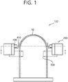
- a nuclear reactor building passive cooling system 100 (hereinafter, referred to as a cooling system) according to the present embodiment includes a cooling water storage reservoir 200.
- the cooling water storage reservoir 200 may be disposed in an upper area of an outer circumference of a nuclear reactor building 10.
- the cooling water storage reservoir 200 may supply cooling water to the inside of the nuclear reactor building 10, as needed, and in this case, even if main power of a reactor facility is loss, the cooling water storage reservoir 200 may be disposed in an upper area of the nuclear reactor building 10 so as to supply cooling water by gravity. However, when it is necessary to adjust a supply cooling water flow to the nuclear reactor building 10, the height of the cooling water storage reservoir 200 may be changed.
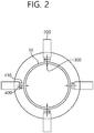
- the cooling water storage reservoir 200 may be disposed in the plural, FIG. 2 illustrates an embodiment in which four cooling water storage reservoir 200 are provided, and the number of the cooling water storage reservoir 200 is not limited thereto.
- a first heat exchanger 300 is connected to the cooling water storage reservoir 200.
- One side of the first heat exchanger 300 is disposed inside the cooling water storage reservoir 200, and the other side thereof extends into the inside of the nuclear reactor building 10 so that the nuclear reactor building 10 is cooled by cooling water contained in the cooling water storage reservoir 200.
- the first heat exchanger 300 will be described in more details with reference to the accompanying drawings.
- cooling water contained in the cooling water storage reservoir 200 may be contained while partitioned inside the cooling water storage reservoir 200.
- the cooling water storage reservoir 200 according to the present embodiment will be described in more details with reference to the accompanying drawings. However, description about elements mentioned above will be omitted, and like reference numerals refer to like elements.
- FIG. 3 is a cross-sectional view schematically illustrating a cooling water storage reservoir of a nuclear reactor building passive cooling system according to the present embodiment
- FIG. 4 is a cross-sectional view illustrating a cooling water storage reservoir of a nuclear reactor building passive cooling system according to the present embodiment taken along line II-II' of FIG. 1 .
- the cooling water storage reservoir 200 includes a storage tank 200a.
- the storage tank 200a may form an outer shape of the cooling water storage reservoir 200 and may be supported to an outer wall of the nuclear reactor building 10.
- the storage tank 200a forms a space for receiving cooling water therein and may be provided in a substantially cubic shape, but a shape of the storage tank 200a is not limited thereto.
- a partition part 210 for partitioning a receiving space of the cooling water is provided at the inside of the storage tank 200a.
- the partition part 210 may be provided as a partition 210a.
- the partition 210a disposed between an upper wall and a lower wall of the storage tank 200a forms a first storage tank 200aa adjacent to the nuclear reactor building 10 and a second storage tank 200ab separated from the first storage tank 200aa .
- a capacity of the second storage tank 200ab may be set to be greater than a capacity of the first storage tank 200aa.
- the capacity of the first storage tank 200aa may be equal to or less than 50% of the total capacity of the storage tank 200a.
- the first heat exchanger 300 is connected to the first storage tank 200aa and the second storage tank 200ab.
- the first heat exchanger 300 may include a outlet pipe 310 connected to the first storage tank 200aa, an inlet pipe 320 connected to the second storage tank 200ab, and a heat exchange unit 330 disposed between the outlet pipe 310 and the inlet pipe 320. Accordingly, the first heat exchanger 300 may circulate cooling water in the second storage tank 200ab in a direction toward the first storage tank 200aa, thereby cooling the nuclear reactor building 10.
- the present embodiments described an example in which the outlet pipe 310 and the inlet pipe 320 of the first heat exchanger 300 are respectively connected to the first storage tank 200aa and the second storage tank 200ab.
- this is merely an example of the present embodiment, and the outlet pipe 310 and the inlet pipe 320 of the first heat exchanger 300 extends to the inside of the first storage tank 200aa, as shown in FIG. 8 .
- a steam outlet H1 is formed in an upper wall of the first storage tank 200aa.
- the steam outlet H1 enables steam generating by heating cooling water of the first storage tank 200aa when cooling the nuclear reactor building 10 to be discharged to the outside. Therefore, the storage tank 200a can be prevented from being broken or damaged due to a change in an internal pressure.
- a water level reduction delay unit 220 may be installed in a steam discharge port H1 may be disposed.
- the water level reduction delay unit 220 separates droplets and moisture from steam discharged from the first storage 200aa to the outside so that the separated moisture returns to the first storage tank 200aa.
- the water level reduction delay unit 220 may be provided as a moisture separator, and may delay cooling water level reduction in the storage tank 200a so as to enable passive cooling of the nuclear reactor building 10 for a long time.
- a passive alarm unit 230 may be installed above the water level delay unit 220. In the case of a design basis accident and severe accident, the passive alarm unit 230 may give an alarm to perform cooling of the nuclear reactor building 10. When vapor is introduced into the steam discharging port H1, the passive alarm unit 230 may generate an alarm or turn on alarm lamp based on vapor flow.
- the passive alarm unit 230 may be provided as a sound alarm device capable of generating noise in response to occurrence of pressure, or as an emergency lamp alarm device configured to turn on an emergency warning lamp by a self power generator such as a propeller which rotates in accordance with vapor flow.
- a self power generator such as a propeller which rotates in accordance with vapor flow.
- the passive alarm unit 230 may be implemented as any of various configurations capable of passively providing an alarm even without power supplied from the outside.
- the passive alarm unit 230 may alarm an operation of cooling the nuclear reactor building 10 so as to primarily inform the surroundings of the occurrence of the accident, and may later on notify whether pressure of the nuclear reactor building 10 is increased or decreased.
- a pressure regulator H2 is formed in an upper wall of the second storage tank 200ab.
- the pressure regulator H2 maintains an internal pressure of the second storage tank 200ab to be equal to an external atmospheric pressure irrespective of an internal pressure of the first storage tank 200aa.
- Filters F1 and F1 are mounted in the steam outlet H1 and the pressure regulator H2, respectively.
- the filters F1 and F2 prevent harmful substances, for example, radioactive materials that may be entered from the inside of the nuclear reactor building 10 into the storage tank 200a from being discharged to outer air.
- an inlet connecting the first storage tank 200aa and the second storage tank 200ab may be provided in a lower portion of the partition 210a.
- the inlet may be provided as a unidirectional valve 210aa.
- the unidirectional valve 210aa allows cooling water in the side of the second storage tank 200ab to flow to the side of the first storage tank 200aa, and prevents cooling water in the first storage tank 200aa from flowing into the second storage tank 200ab.
- the unidirectional valve 210aa may be provided as a floating valve or a check valve, and may be provided as a plurality of unidirectional valves installed on the partition 210a.
- the unidirectional valve 210aa when the unidirectional valve 210aa is provided as a plurality of unidirectional valves, the plurality of unidirectional valves may be arranged at the same height, and, although FIG. 4 shows that three unidirectional valves 210aa are provided, the number of unidirectional valves 210aa is not limited.
- the unidirectional valve 210aa forms a path that may enable cooling water received in the second storage tank to enter into the first storage tank 200aa.
- the first storage tank 200aa connected to the outlet pipe 310 quickly reaches a saturation temperature. This contributes to stabilization of a heat removal performance of the cooling system 100 and thus a temperature and pressure of the nuclear reactor building 10 are quickly stabilized.
- the reason why a capacity of the first storage tank 200aa is smaller than that of the second storage tank 200ab as described above is intended to achieve such an effect.
- the first storage tank 200aa reaches a saturation temperature, and cooling water received in the first storage tank 200aa is heated and discharged to the outside through the steam outlet H1. Therefore, a water level difference occurs between the first storage tank 200aa and the second storage tank 200ab. Therefore, cooling water in the second storage tank 200ab is entered into the first storage tank 200aa through the unidirectional valve 210aa so as to eliminate the water level difference.
- the cooling water storage reservoir 200 constantly maintains a heat removal performance of the cooling system 100 from the beginning of the case of a design basis accident and severe accident to enable a pressure and temperature of the nuclear reactor building 10 to gradually reduce. Therefore, in a conventional cooling system, while a temperature and pressure of the nuclear reactor building 10 decrease, a heat removal performance decreases due to increase of the cooling water temperature and a problem can be solved that the pressure and temperature of the nuclear reactor building 10 is thus re-pressurized and reheated.
- the conventional cooling system and the cooling system 100 according to the present embodiment are compared as follows.
- a conventional cooling system operates with temperature and pressure rise of the nuclear reactor building 10 in the event of a cooling water spill accident.
- the conventional cooling system may reduce a temperature and pressure of the nuclear reactor building 10.
- cooling system 100 even if cooling water stored in the first storage tank 200aa is heated, cooling water received in the second storage tank 200ab is naturally entered into the first storage tank 200aa according to steam discharged to outside air. Accordingly, as shown in FIG. 6 , a temperature and pressure of the nuclear reactor building 10 are reduced smoothly in the case of a design basis accident and severe accident, and a problem that the temperature and pressure of the nuclear reactor building 10 rise again.
- the inlet pipe 320 having an orifice mounted thereto may be connected to the second storage tank 200ab (see FIG. 3 ), and the unidirectional valve 210aa may be installed to the partition part 210.
- the unidirectional valve 210aa since cooling water is prevented from flowing from the first storage tank 200aa to the second storage tank 200ab, relatively cold cooling water is constantly introduced to the heat exchanger 300, and therefore, overall heat removal performance may improve further.
- a second heat exchanger 400 may be connected to the first storage tank 200aa.
- An inlet pipe and an outlet pipe of the second heat exchanger 400 extend from the outside of the storage tank 200a into the first storage tank 200aa.
- the second heat exchanger 400 cools cooling water of the first storage tank 200aa through atmosphere.
- the second heat exchanger 400 may be provided as an air-cooled heat exchanger, and may improve cooling performance of the first heat exchanger 300 by cooling the cooling water of the first storage tank 200aa.
- An air inlet part 410 may be provided in an outer wall of the storage tank 200aa.
- the air inlet part 410 may be disposed to surround the second heat exchanger 400 and may be open at the top. In this case, the air inlet part 410 may induce air to flow into the second heat exchanger 400, thereby improving heat transfer performance of the second heat exchanger 400 that can be provided as an air-cooled heat exchanger.
- the air inlet part 410 is provided for Venturi effect, and may have a shape of a Venturi pipe having an open top, but the shape of the air inlet part 400 is not limited.
- FIG. 7 is a flowchart illustrating an operation of a nuclear reactor building passive cooling system according to the present embodiment.
- the cooling system 100 may be operated in the case of a design basis accident and severe accident (S100).
- S100 design basis accident and severe accident
- steam and radioactive materials are discharged from inside the nuclear reactor building 10, thereby increasing a temperature and pressure of an inner space of the nuclear reactor building 10.
- cooling water in the heat exchange unit 330 is heated, and the heated cooling water is entered into the first storage tank 200aa.
- the cooling water received in the second storage tank 200ab is entered into the first heat exchanger 300 to be provided to the heat exchange unit 330.
- the cooling system 100 repeats inflow and outflow and circulates cooling water based on a natural force (S200).
- a temperature of cooling water in the first storage tank 200aa rises to a boiling point (S300).
- the cooling water stored in the second storage tank 200ab maintains an initial temperature.
- a time at which cooling water in the first storage tank 200aa reaches a boiling point becomes shorter than that of a conventional cooling water storage reservoir having the same capacity as that of the cooling water storage reservoir 200 according to the present embodiment. Therefore, the cooling system 100 according to the present embodiment is stabilized through a relatively short transient period.
- cooling water of the first storage tank 200aa evaporates, cooling water of a low temperature of the second storage tank 200ab is naturally entered into the first storage tank 200aa (S400). Accordingly, a heat removal performance of the cooling system 100 is lowered due to increase in a temperature of cooling water stored in the first storage tank 200aa, thereby solving a problem that a pressure and temperature of the nuclear reactor building 10 are re-pressurized and reheated.
- a cooling water storage reservoir and a nuclear reactor building passive cooling system including the same can quickly stabilize a performance of the nuclear reactor building passive cooling system, thereby preventing performance deterioration of the nuclear reactor building passive cooling system.
- cooling water storage reservoir and the nuclear reactor building passive cooling system including the same can continuously reduce a pressure and temperature of the nuclear reactor building, and thus a secondary accident such as destruction of the nuclear reactor building can be suppressed from occurring.
Landscapes
- Physics & Mathematics (AREA)
- Engineering & Computer Science (AREA)
- Plasma & Fusion (AREA)
- General Engineering & Computer Science (AREA)
- High Energy & Nuclear Physics (AREA)
- Structure Of Emergency Protection For Nuclear Reactors (AREA)
Abstract
Description
- The present invention relates to a cooling water storage reservoir and a nuclear reactor building passive cooling system including the same, and more particularly, to a cooling water storage reservoir for cooling a nuclear reactor building and a nuclear reactor building passive cooling system including the same.
- In general, in the case of a design basis accident and severe at a nuclear power plant, a radioactive material is discharged together with steam into the nuclear reactor building and thus a temperature and pressure in the nuclear reactor building rise sharply. In this case, when the rising temperature and pressure are not controlled, the nuclear reactor building may be destroyed. Therefore, a nuclear reactor building cooling system is provided in the nuclear reactor building and thus in case of a design basis accident and a major accident, the rising temperature and pressure may be adjusted.
- However, in the case of a design basis accident and severe accident, it is difficult for an operator to access to control the cooling system, and there is a problem that the cooling system does not operate properly due to a loss of offside power. Therefore, a passive cooling system is applied. The passive cooling system may include a cooling water storage reservoir installed outside the nuclear reactor building and a heat exchanger extended from the cooling water storage reservoir into the nuclear reactor building.
- Therefore, in the case of a design basis accident and severe accident, as the heat exchanger passively operates, the nuclear reactor building is cooled. Here, at the beginning of the accident, thermal energy is smoothly removed by a low temperature of cooling water. However, when a temperature of cooling water rises due to repeated heat exchange, thermal energy may not be completely removed and thus there is a problem that a temperature and pressure of the nuclear reactor building rise again.
- The present invention provides a cooling water storage reservoir, and a nuclear reactor building passive cooling system including the same, the reservoir capable of preventing re-pressurization and reheating of a nuclear reactor building from the cooling of a nuclear reactor building in the case of a design basis accident and severe accident.
- A nuclear reactor building passive cooling system according to the present invention is disposed adjacent to an outer wall of a nuclear reactor building and capable of passively cooling the nuclear reactor building, and the system includes: a storage tank storing cooling water; a partition part arranged within the storage tank and dividing inside of the storage tank into a first storage tank and a second storage tank to separate the cooling water; a first heat exchanger extending from the storage tank to the nuclear reactor building and cooling the nuclear reactor building on the basis of the cooling water; and a unidirectional valve provided on the partition part and allowing the cooling water of the second storage tank to flow into the first storage tank when a water level of the first storage tank is reduced.
- The system may further include a second heat exchanger extending from the first storage tank to outside of the storage tank to cool the cooling water of the first storage tank.
- The system may further include an air inlet part provided on an outer surface of the storage tank to induce air to flow into the second heat exchanger.
- The air inlet part may be disposed to surround the second heat exchanger and provided in a tube shape having an open top.
- The air inlet part may be provided in a venturi tube shape having an open top.
- The unidirectional valve may include at least one of a floating valve or a check valve.
- The first heat exchanger may include: an inlet pipe into which the cooling water is introduced from the second storage tank, an outlet pipe along which the cooling water provided from the inlet pipe into the first storage tank; and a heat exchange unit disposed between the inlet pipe and the outlet pipe.
- The first heat exchanger may include: an inlet pipe into which the cooling water is introduced from the first storage tank, an outlet pipe along which the cooling water provided from the inlet pipe returns back to the first storage tank, and a heat exchange unit disposed between the inlet pipe and the outlet pipe.
- A capacity of the first storage tank may be smaller than a capacity of the second storage tank.
- Meanwhile, a cooling water storage reservoir according to the present invention is capable of passively cooling a building and includes: a storage tank storing cooling water; a partition part arranged within the storage tank and dividing inside of the storage tank into a first storage tank and a second storage tank to separate the cooling water; a first heat exchanger extending from the storage tank to the building and cooling the nuclear building on the basis of the cooling water; and a unidirectional valve provided on the partition part and allowing the cooling water of the second storage tank to flow into the first storage tank when the water level of the first storage tank is reduced.
- A cooling water storage reservoir and a nuclear reactor building passive cooling system including the same according to the present invention can quickly stabilize a performance of the nuclear reactor building passive cooling system, thereby preventing performance deterioration of the nuclear reactor building passive cooling system.
- Further, a cooling water storage reservoir and a nuclear reactor building passive cooling system including the same according to the present invention can continuously reduce a pressure and temperature of the nuclear reactor building, thereby suppressing occurrence of a secondary accident such as destruction of the nuclear reactor building.
- The technical effects of the present invention are not limited to the effects mentioned above, and other technical effects not mentioned can be clearly understood by those skilled in the art from the following description.
-
-
FIG. 1 is a conceptual view schematically illustrating a nuclear reactor building passive cooling system according to the present embodiment; -
FIG. 2 is a cross-sectional view illustrating a nuclear reactor building passive cooling system according to the present embodiment taken along line I-I' ofFIG. 1 ; -
FIG. 3 is a cross-sectional view schematically illustrating a cooling water storage reservoir of a nuclear reactor building passive cooling system according to the present embodiment; -
FIG. 4 is a cross-sectional view illustrating a cooling water storage reservoir of a nuclear reactor building passive cooling system according to the present embodiment taken along line II-II' ofFIG. 1 ; -
FIG. 5 is a graph illustrating changes in an internal pressure and temperature of a nuclear reactor building according to use of a cooling water storage reservoir of a conventional passive cooling system; -
FIG. 6 is a graph illustrating changes in an internal pressure and temperature of a nuclear reactor building according to use of a cooling water storage reservoir of a nuclear reactor building passive cooling system according to the present embodiment; -
FIG. 7 is a flowchart illustrating an operation of a nuclear reactor building passive cooling system according to the present embodiment; and -
FIG. 8 is a cross-sectional view schematically illustrating a cooling water storage reservoir of a nuclear reactor building passive cooling system according to another embodiment. - Hereinafter, an embodiment according to the present invention will be described in detail with reference to the attached drawings. However, it should be understood that the present embodiment is not limited to embodiments described hereinafter, but may be implemented in various forms, and the present embodiments enable to complete the disclosure of the present invention and are provided to know completely the scope of the invention to those skilled in the art. In the drawing, shapes of elements may be exaggeratingly expressed for better description, and like reference numerals designate like elements in the drawing.
- As shown in
FIGS. 1 and2 , a nuclear reactor building passive cooling system 100 (hereinafter, referred to as a cooling system) according to the present embodiment includes a coolingwater storage reservoir 200. - The cooling
water storage reservoir 200 may be disposed in an upper area of an outer circumference of anuclear reactor building 10. The coolingwater storage reservoir 200 may supply cooling water to the inside of thenuclear reactor building 10, as needed, and in this case, even if main power of a reactor facility is loss, the coolingwater storage reservoir 200 may be disposed in an upper area of thenuclear reactor building 10 so as to supply cooling water by gravity. However, when it is necessary to adjust a supply cooling water flow to thenuclear reactor building 10, the height of the coolingwater storage reservoir 200 may be changed. - The cooling
water storage reservoir 200 may be disposed in the plural,FIG. 2 illustrates an embodiment in which four coolingwater storage reservoir 200 are provided, and the number of the coolingwater storage reservoir 200 is not limited thereto. - Meanwhile, a
first heat exchanger 300 is connected to the coolingwater storage reservoir 200. One side of thefirst heat exchanger 300 is disposed inside the coolingwater storage reservoir 200, and the other side thereof extends into the inside of thenuclear reactor building 10 so that thenuclear reactor building 10 is cooled by cooling water contained in the coolingwater storage reservoir 200. Thefirst heat exchanger 300 will be described in more details with reference to the accompanying drawings. - Meanwhile, the cooling water contained in the cooling
water storage reservoir 200 may be contained while partitioned inside the coolingwater storage reservoir 200. Hereinafter, the coolingwater storage reservoir 200 according to the present embodiment will be described in more details with reference to the accompanying drawings. However, description about elements mentioned above will be omitted, and like reference numerals refer to like elements. -
FIG. 3 is a cross-sectional view schematically illustrating a cooling water storage reservoir of a nuclear reactor building passive cooling system according to the present embodiment, andFIG. 4 is a cross-sectional view illustrating a cooling water storage reservoir of a nuclear reactor building passive cooling system according to the present embodiment taken along line II-II' ofFIG. 1 . - As shown in
FIGS. 3 and4 , the coolingwater storage reservoir 200 according to the present embodiment includes astorage tank 200a. Thestorage tank 200a may form an outer shape of the coolingwater storage reservoir 200 and may be supported to an outer wall of thenuclear reactor building 10. Here, thestorage tank 200a forms a space for receiving cooling water therein and may be provided in a substantially cubic shape, but a shape of thestorage tank 200a is not limited thereto. - At the inside of the
storage tank 200a, apartition part 210 for partitioning a receiving space of the cooling water is provided. Thepartition part 210 may be provided as apartition 210a. Thepartition 210a disposed between an upper wall and a lower wall of thestorage tank 200a forms a first storage tank 200aa adjacent to thenuclear reactor building 10 and a second storage tank 200ab separated from the first storage tank 200aa. - In this case, a capacity of the second storage tank 200ab may be set to be greater than a capacity of the first storage tank 200aa. For example, the capacity of the first storage tank 200aa may be equal to or less than 50% of the total capacity of the
storage tank 200a. - In addition, the
first heat exchanger 300 is connected to the first storage tank 200aa and the second storage tank 200ab. Thefirst heat exchanger 300 may include aoutlet pipe 310 connected to the first storage tank 200aa, aninlet pipe 320 connected to the second storage tank 200ab, and aheat exchange unit 330 disposed between theoutlet pipe 310 and theinlet pipe 320. Accordingly, thefirst heat exchanger 300 may circulate cooling water in the second storage tank 200ab in a direction toward the first storage tank 200aa, thereby cooling thenuclear reactor building 10. - However, the present embodiments described an example in which the
outlet pipe 310 and theinlet pipe 320 of thefirst heat exchanger 300 are respectively connected to the first storage tank 200aa and the second storage tank 200ab. However, this is merely an example of the present embodiment, and theoutlet pipe 310 and theinlet pipe 320 of thefirst heat exchanger 300 extends to the inside of the first storage tank 200aa, as shown inFIG. 8 . - A steam outlet H1 is formed in an upper wall of the first storage tank 200aa. The steam outlet H1 enables steam generating by heating cooling water of the first storage tank 200aa when cooling the
nuclear reactor building 10 to be discharged to the outside. Therefore, thestorage tank 200a can be prevented from being broken or damaged due to a change in an internal pressure. - In addition, a water level
reduction delay unit 220 may be installed in a steam discharge port H1 may be disposed. The water levelreduction delay unit 220 separates droplets and moisture from steam discharged from the first storage 200aa to the outside so that the separated moisture returns to the first storage tank 200aa. - The water level
reduction delay unit 220 may be provided as a moisture separator, and may delay cooling water level reduction in thestorage tank 200a so as to enable passive cooling of thenuclear reactor building 10 for a long time. - In addition, a
passive alarm unit 230 may be installed above the waterlevel delay unit 220. In the case of a design basis accident and severe accident, thepassive alarm unit 230 may give an alarm to perform cooling of thenuclear reactor building 10. When vapor is introduced into the steam discharging port H1, thepassive alarm unit 230 may generate an alarm or turn on alarm lamp based on vapor flow. - For example, the
passive alarm unit 230 may be provided as a sound alarm device capable of generating noise in response to occurrence of pressure, or as an emergency lamp alarm device configured to turn on an emergency warning lamp by a self power generator such as a propeller which rotates in accordance with vapor flow. - However, this is merely an example of the present embodiment, and the
passive alarm unit 230 may be implemented as any of various configurations capable of passively providing an alarm even without power supplied from the outside. - When a design basis accident or severe accident occurs, the
passive alarm unit 230 may alarm an operation of cooling thenuclear reactor building 10 so as to primarily inform the surroundings of the occurrence of the accident, and may later on notify whether pressure of thenuclear reactor building 10 is increased or decreased. - A pressure regulator H2 is formed in an upper wall of the second storage tank 200ab. The pressure regulator H2 maintains an internal pressure of the second storage tank 200ab to be equal to an external atmospheric pressure irrespective of an internal pressure of the first storage tank 200aa.
- Filters F1 and F1 are mounted in the steam outlet H1 and the pressure regulator H2, respectively. When the
first heat exchanger 300 is broken or damaged, the filters F1 and F2 prevent harmful substances, for example, radioactive materials that may be entered from the inside of thenuclear reactor building 10 into thestorage tank 200a from being discharged to outer air. - Meanwhile, an inlet connecting the first storage tank 200aa and the second storage tank 200ab may be provided in a lower portion of the
partition 210a. The inlet may be provided as a unidirectional valve 210aa. The unidirectional valve 210aa allows cooling water in the side of the second storage tank 200ab to flow to the side of the first storage tank 200aa, and prevents cooling water in the first storage tank 200aa from flowing into the second storage tank 200ab. - The unidirectional valve 210aa may be provided as a floating valve or a check valve, and may be provided as a plurality of unidirectional valves installed on the
partition 210a. - However, when the unidirectional valve 210aa is provided as a plurality of unidirectional valves, the plurality of unidirectional valves may be arranged at the same height, and, although
FIG. 4 shows that three unidirectional valves 210aa are provided, the number of unidirectional valves 210aa is not limited. - The unidirectional valve 210aa forms a path that may enable cooling water received in the second storage tank to enter into the first storage tank 200aa.
- More specifically, in the case of a design basis accident and severe accident, the first storage tank 200aa connected to the
outlet pipe 310 quickly reaches a saturation temperature. This contributes to stabilization of a heat removal performance of thecooling system 100 and thus a temperature and pressure of thenuclear reactor building 10 are quickly stabilized. The reason why a capacity of the first storage tank 200aa is smaller than that of the second storage tank 200ab as described above is intended to achieve such an effect. - Thereafter, the first storage tank 200aa reaches a saturation temperature, and cooling water received in the first storage tank 200aa is heated and discharged to the outside through the steam outlet H1. Therefore, a water level difference occurs between the first storage tank 200aa and the second storage tank 200ab. Therefore, cooling water in the second storage tank 200ab is entered into the first storage tank 200aa through the unidirectional valve 210aa so as to eliminate the water level difference.
- Accordingly, the cooling
water storage reservoir 200 constantly maintains a heat removal performance of thecooling system 100 from the beginning of the case of a design basis accident and severe accident to enable a pressure and temperature of thenuclear reactor building 10 to gradually reduce. Therefore, in a conventional cooling system, while a temperature and pressure of thenuclear reactor building 10 decrease, a heat removal performance decreases due to increase of the cooling water temperature and a problem can be solved that the pressure and temperature of thenuclear reactor building 10 is thus re-pressurized and reheated. - More specifically, the conventional cooling system and the
cooling system 100 according to the present embodiment are compared as follows. - As shown in
FIGS. 5 and6 , a conventional cooling system operates with temperature and pressure rise of thenuclear reactor building 10 in the event of a cooling water spill accident. In this case, the conventional cooling system may reduce a temperature and pressure of thenuclear reactor building 10. - However, in an existing cooling system, efficiency of the
cooling system 100 is significantly reduced as cooing water is heated after a predetermined time passes. Thus, as shown in section "A" indicated inFIG. 5 , there is a problem that temperature and pressure of thenuclear reactor building 10 are increased again. In particular, in a section where temperature and pressure of thenuclear reactor building 10 are increased again for a long time, there is a possibility that a reactor operator takes a wrong action to secure an additional cooling means in order to prevent the re-pressure of thenuclear reactor building 10. - However, in the
cooling system 100 according to the present embodiment, even if cooling water stored in the first storage tank 200aa is heated, cooling water received in the second storage tank 200ab is naturally entered into the first storage tank 200aa according to steam discharged to outside air. Accordingly, as shown inFIG. 6 , a temperature and pressure of thenuclear reactor building 10 are reduced smoothly in the case of a design basis accident and severe accident, and a problem that the temperature and pressure of thenuclear reactor building 10 rise again. - Meanwhile, again referring to
FIGS. 3 and4 , in thecooling system 100 according to the present embodiment, theinlet pipe 320 having an orifice mounted thereto may be connected to the second storage tank 200ab (seeFIG. 3 ), and the unidirectional valve 210aa may be installed to thepartition part 210. In this case, since cooling water is prevented from flowing from the first storage tank 200aa to the second storage tank 200ab, relatively cold cooling water is constantly introduced to theheat exchanger 300, and therefore, overall heat removal performance may improve further. - In addition, a
second heat exchanger 400 may be connected to the first storage tank 200aa. An inlet pipe and an outlet pipe of thesecond heat exchanger 400 extend from the outside of thestorage tank 200a into the first storage tank 200aa. Thesecond heat exchanger 400 cools cooling water of the first storage tank 200aa through atmosphere. Accordingly, thesecond heat exchanger 400 may be provided as an air-cooled heat exchanger, and may improve cooling performance of thefirst heat exchanger 300 by cooling the cooling water of the first storage tank 200aa. - An
air inlet part 410 may be provided in an outer wall of the storage tank 200aa. Theair inlet part 410 may be disposed to surround thesecond heat exchanger 400 and may be open at the top. In this case, theair inlet part 410 may induce air to flow into thesecond heat exchanger 400, thereby improving heat transfer performance of thesecond heat exchanger 400 that can be provided as an air-cooled heat exchanger. - The
air inlet part 410 is provided for Venturi effect, and may have a shape of a Venturi pipe having an open top, but the shape of theair inlet part 400 is not limited. - Hereinafter, an operation of a nuclear reactor building passive cooling system according to the present embodiment will be described in more detail. However, a detailed description of the above-described constituent elements is omitted and constituent elements identical to or corresponding to those according to the foregoing embodiment are denoted by the same reference numerals.
-
FIG. 7 is a flowchart illustrating an operation of a nuclear reactor building passive cooling system according to the present embodiment. - As shown in
FIG. 7 , thecooling system 100 according to the present embodiment may be operated in the case of a design basis accident and severe accident (S100). In this case, steam and radioactive materials are discharged from inside thenuclear reactor building 10, thereby increasing a temperature and pressure of an inner space of thenuclear reactor building 10. - Therefore, cooling water in the
heat exchange unit 330 is heated, and the heated cooling water is entered into the first storage tank 200aa. In this case, the cooling water received in the second storage tank 200ab is entered into thefirst heat exchanger 300 to be provided to theheat exchange unit 330. In this manner, thecooling system 100 repeats inflow and outflow and circulates cooling water based on a natural force (S200). - After an accident occurs, as a time has elapsed, a temperature of cooling water in the first storage tank 200aa rises to a boiling point (S300). However, in a state in which cooling water stored in the second storage tank 200ab is not mixed with the cooling water in the first storage tank 200aa, the cooling water stored in the second storage tank 200ab maintains an initial temperature.
- Further, a time at which cooling water in the first storage tank 200aa reaches a boiling point becomes shorter than that of a conventional cooling water storage reservoir having the same capacity as that of the cooling
water storage reservoir 200 according to the present embodiment. Therefore, thecooling system 100 according to the present embodiment is stabilized through a relatively short transient period. - Further, as cooling water of the first storage tank 200aa evaporates, cooling water of a low temperature of the second storage tank 200ab is naturally entered into the first storage tank 200aa (S400). Accordingly, a heat removal performance of the
cooling system 100 is lowered due to increase in a temperature of cooling water stored in the first storage tank 200aa, thereby solving a problem that a pressure and temperature of thenuclear reactor building 10 are re-pressurized and reheated. - In addition, temperature increases faster in the first storage tank 200aa than in the second storage tank 200ab, and, as the
second heat exchanger 400 is provided, heat in the first storage tank 200aa may be constantly removed by atmosphere. As a result, there is an advantage in increasing a total heat removal amount of thecooling system 100. In addition, if the Venturi shape applies to theair inlet part 410, air cooling performance may further improve. - Therefore, a cooling water storage reservoir and a nuclear reactor building passive cooling system including the same can quickly stabilize a performance of the nuclear reactor building passive cooling system, thereby preventing performance deterioration of the nuclear reactor building passive cooling system.
- Further, the cooling water storage reservoir and the nuclear reactor building passive cooling system including the same can continuously reduce a pressure and temperature of the nuclear reactor building, and thus a secondary accident such as destruction of the nuclear reactor building can be suppressed from occurring.
- The embodiments of the present invention described above and shown in the drawings should not be construed as limiting the technical idea of the present invention. The scope of the present invention is limited only by the matters described in the claims, and those skilled in the art can modify the technical idea of the present invention in various forms. Accordingly, such improvements and modifications will fall within the scope of the present invention as long as they are obvious to those skilled in the art.
Claims (10)
- A nuclear reactor building passive cooling system disposed adjacent to an outer wall of a nuclear reactor building and capable of passively cooling the nuclear reactor building, the system comprising:a storage tank storing cooling water;a partition part arranged within the storage tank and dividing inside of the storage tank into a first storage tank and a second storage tank to separate the cooling water;a first heat exchanger extending from the storage tank to the nuclear reactor building and cooling the nuclear reactor building on the basis of the cooling water; anda unidirectional valve provided on the partition part and allowing the cooling water of the second storage tank to be introduced into the first storage tank when a water level of the first storage tank is reduced.
- The system of claim 1, further comprising a second heat exchanger extending from the first storage tank to outside of the storage tank to cool the cooling water of the first storage tank.
- The system of claim 2, further comprising an air inlet part provided on an outer surface of the storage tank to induce air to flow into the second heat exchanger.
- The system of claim 3, wherein the air inlet part is disposed to surround the second heat exchanger and provided in a tube shape having an open top.
- The system of claim 3, wherein the air inlet part is provided in a venturi tube shape having an open top.
- The system of claim 1, wherein the unidirectional valve comprises at least one of a floating valve or a check valve.
- The system of claim 1, wherein the first heat exchanger comprises an inlet pipe into which the cooling water is introduced from the second storage tank, an outlet pipe along which the cooling water provided from the inlet pipe into the first storage tank; and a heat exchange unit disposed between the inlet pipe and the outlet pipe.
- The system of claim 1, wherein the first heat exchanger comprises an inlet pipe into which the cooling water is introduced from the first storage tank, an outlet pipe along which the cooling water provided from the inlet pipe returns back to the first storage tank, and a heat exchange unit disposed between the inlet pipe and the outlet pipe.
- The system of claim 1, wherein a capacity of the first storage tank is smaller than a capacity of the second storage tank.
- A cooling water storage reservoir capable of passively cooling a building, the cooling water tank comprising:a storage tank storing cooling water;a partition part arranged within the storage tank and dividing inside of the storage tank into a first storage tank and a second storage tank to separate the cooling water;a first heat exchanger extending from the storage tank to the building and cooling the nuclear building based on the cooling water; anda unidirectional valve provided on the partition part and allowing the cooling water of the second storage tank to flow into the first storage tank when the water level of the first storage tank is reduced.
Applications Claiming Priority (3)
| Application Number | Priority Date | Filing Date | Title |
|---|---|---|---|
| KR1020160126859 | 2016-09-30 | ||
| KR1020160126864A KR101832067B1 (en) | 2016-09-30 | 2016-09-30 | Coolant tank, and containment passive cooling system including the same |
| PCT/KR2017/010875 WO2018062916A1 (en) | 2016-09-30 | 2017-09-28 | Coolant tank, and passive containment cooling system comprising same |
Publications (3)
| Publication Number | Publication Date |
|---|---|
| EP3522175A1 true EP3522175A1 (en) | 2019-08-07 |
| EP3522175A4 EP3522175A4 (en) | 2020-03-11 |
| EP3522175B1 EP3522175B1 (en) | 2021-03-03 |
Family
ID=61760025
Family Applications (1)
| Application Number | Title | Priority Date | Filing Date |
|---|---|---|---|
| EP17856802.8A Active EP3522175B1 (en) | 2016-09-30 | 2017-09-28 | Passive containment cooling system comprising a coolant tank |
Country Status (3)
| Country | Link |
|---|---|
| US (1) | US11081242B2 (en) |
| EP (1) | EP3522175B1 (en) |
| WO (1) | WO2018062916A1 (en) |
Families Citing this family (1)
| Publication number | Priority date | Publication date | Assignee | Title |
|---|---|---|---|---|
| CN116631658A (en) * | 2023-05-19 | 2023-08-22 | 中国核电工程有限公司 | Passive and active safety system and arrangement thereof |
Family Cites Families (16)
| Publication number | Priority date | Publication date | Assignee | Title |
|---|---|---|---|---|
| US5295169A (en) * | 1990-10-15 | 1994-03-15 | Hitachi, Ltd. | Reactor containment facilities |
| JP3159820B2 (en) | 1993-02-12 | 2001-04-23 | 株式会社日立製作所 | Reactor containment equipment |
| JPH06258491A (en) * | 1993-03-02 | 1994-09-16 | Toshiba Eng Co Ltd | Condensate storage tank water supply facility |
| JPH085772A (en) | 1994-06-17 | 1996-01-12 | Hitachi Ltd | Containment vessel |
| JPH085882A (en) | 1994-06-22 | 1996-01-12 | Olympus Optical Co Ltd | Lens holding body |
| KR100597723B1 (en) * | 2004-02-10 | 2006-07-10 | 한국원자력연구소 | Core melt passive cooling and confinement |
| KR101301981B1 (en) * | 2011-02-17 | 2013-10-10 | 주식회사 티알엑서지 | Cooling and heating system for building |
| JP2012198168A (en) | 2011-03-23 | 2012-10-18 | Toshiba Corp | Reactor container cooling apparatus and reactor building with the reactor container cooling apparatus |
| KR101250516B1 (en) * | 2011-09-08 | 2013-04-03 | 한전원자력연료 주식회사 | passive auxiliary condensing apparatus for nuclear power plant |
| KR101389276B1 (en) * | 2012-07-13 | 2014-04-25 | 한국원자력연구원 | Passive Safety System of Integral Reactor |
| KR101473377B1 (en) * | 2013-05-09 | 2014-12-24 | 한국원자력연구원 | Passive containment spray system |
| KR101528223B1 (en) * | 2014-10-01 | 2015-06-12 | 한국원자력연구원 | Passive safety facility and nuclear power plant having the same |
| US10115488B2 (en) | 2013-10-04 | 2018-10-30 | Korea Atomic Energy Research Institute | Passive safety equipment for a nuclear power plant |
| CN104078085B (en) * | 2014-06-04 | 2016-10-05 | 中国核电工程有限公司 | A kind of built-in material-changing water tank of containment with water scrub function |
| KR101570080B1 (en) * | 2014-09-22 | 2015-11-19 | 한국원자력연구원 | Nuclear power plant |
| KR101659864B1 (en) * | 2015-05-13 | 2016-09-26 | 한국원자력연구원 | Nuclear power plant |
-
2017
- 2017-09-28 WO PCT/KR2017/010875 patent/WO2018062916A1/en not_active Ceased
- 2017-09-28 US US16/338,247 patent/US11081242B2/en active Active
- 2017-09-28 EP EP17856802.8A patent/EP3522175B1/en active Active
Also Published As
| Publication number | Publication date |
|---|---|
| US20190237207A1 (en) | 2019-08-01 |
| US11081242B2 (en) | 2021-08-03 |
| WO2018062916A1 (en) | 2018-04-05 |
| EP3522175A4 (en) | 2020-03-11 |
| EP3522175B1 (en) | 2021-03-03 |
Similar Documents
| Publication | Publication Date | Title |
|---|---|---|
| KR101832067B1 (en) | Coolant tank, and containment passive cooling system including the same | |
| US10811148B2 (en) | Self-diagnosis and accident-handling unmanned nuclear reactor | |
| KR101594440B1 (en) | Shutdown cooling facility and nuclear power plant having the same | |
| KR101659864B1 (en) | Nuclear power plant | |
| KR20110106850A (en) | Reactor Vessel Coolant Deflection Shield | |
| RU2682901C2 (en) | Floating nuclear power reactor with self-cooling containment structure and emergency heat exchange system | |
| CN107636769A (en) | The liquid metal cooling nuclear reactor of nuclear reactor, especially compact | |
| KR101535479B1 (en) | Depressurization system of reactor coolant system and nuclear power plant having the same | |
| KR101374751B1 (en) | Passive decay heat removal system using organoic fluid, method of driving heat removal system | |
| KR101456170B1 (en) | Passive containment air cooling device and system with isolated pressure boundary | |
| EP3522175B1 (en) | Passive containment cooling system comprising a coolant tank | |
| JP2020023965A (en) | Vehicle cooling system | |
| US11195632B2 (en) | Cooling water reservoir and nuclear reactor building passive cooling system | |
| KR101806043B1 (en) | Coolant tank, and containment passive cooling system including the same | |
| KR101790451B1 (en) | Coolant supplying system, and reactor building passive cooling system including the same | |
| US20190252083A1 (en) | Cooling water reservoir and passive cooling system comprising same for reactor containment building | |
| KR101502395B1 (en) | Passive containment spray and cooling system and nuclear power plant having the same | |
| KR101677981B1 (en) | Safty system for a nuclear power plant and nuclear power plant having the same | |
| KR101790450B1 (en) | Coolant tank, and nuclear reactor building passive cooling system including the same | |
| KR102425224B1 (en) | Coolant tank, and containment passive cooling system including the same | |
| EP3492811B1 (en) | Nuclear power plants | |
| EP3522174B1 (en) | Nuclear reactor building with passive cooling system comprising a cooling water storage reservoir | |
| KR101805316B1 (en) | Coolant tank, and containment passive cooling system including the same | |
| KR102643953B1 (en) | Passive cooling apparatus for nuclear reactor | |
| KR102458247B1 (en) | Passive cooling installation of atomic reactor and passive cooling method thereof |
Legal Events
| Date | Code | Title | Description |
|---|---|---|---|
| STAA | Information on the status of an ep patent application or granted ep patent |
Free format text: STATUS: THE INTERNATIONAL PUBLICATION HAS BEEN MADE |
|
| PUAI | Public reference made under article 153(3) epc to a published international application that has entered the european phase |
Free format text: ORIGINAL CODE: 0009012 |
|
| STAA | Information on the status of an ep patent application or granted ep patent |
Free format text: STATUS: REQUEST FOR EXAMINATION WAS MADE |
|
| 17P | Request for examination filed |
Effective date: 20190329 |
|
| AK | Designated contracting states |
Kind code of ref document: A1 Designated state(s): AL AT BE BG CH CY CZ DE DK EE ES FI FR GB GR HR HU IE IS IT LI LT LU LV MC MK MT NL NO PL PT RO RS SE SI SK SM TR |
|
| AX | Request for extension of the european patent |
Extension state: BA ME |
|
| DAV | Request for validation of the european patent (deleted) | ||
| DAX | Request for extension of the european patent (deleted) | ||
| A4 | Supplementary search report drawn up and despatched |
Effective date: 20200212 |
|
| RIC1 | Information provided on ipc code assigned before grant |
Ipc: B65D 88/02 20060101ALI20200206BHEP Ipc: G21C 9/012 20060101AFI20200206BHEP Ipc: B65D 90/32 20060101ALI20200206BHEP Ipc: G21C 15/18 20060101ALI20200206BHEP Ipc: G21C 13/02 20060101ALI20200206BHEP Ipc: B65D 90/52 20060101ALI20200206BHEP |
|
| REG | Reference to a national code |
Ref country code: DE Ref legal event code: R079 Ref document number: 602017034071 Country of ref document: DE Free format text: PREVIOUS MAIN CLASS: G21C0015180000 Ipc: G21C0009012000 |
|
| GRAP | Despatch of communication of intention to grant a patent |
Free format text: ORIGINAL CODE: EPIDOSNIGR1 |
|
| STAA | Information on the status of an ep patent application or granted ep patent |
Free format text: STATUS: GRANT OF PATENT IS INTENDED |
|
| RIC1 | Information provided on ipc code assigned before grant |
Ipc: B65D 90/32 20060101ALI20200917BHEP Ipc: B65D 88/02 20060101ALI20200917BHEP Ipc: G21C 15/18 20060101ALI20200917BHEP Ipc: G21C 9/012 20060101AFI20200917BHEP Ipc: B65D 90/52 20060101ALI20200917BHEP Ipc: G21C 13/02 20060101ALI20200917BHEP |
|
| INTG | Intention to grant announced |
Effective date: 20201014 |
|
| GRAS | Grant fee paid |
Free format text: ORIGINAL CODE: EPIDOSNIGR3 |
|
| GRAA | (expected) grant |
Free format text: ORIGINAL CODE: 0009210 |
|
| STAA | Information on the status of an ep patent application or granted ep patent |
Free format text: STATUS: THE PATENT HAS BEEN GRANTED |
|
| AK | Designated contracting states |
Kind code of ref document: B1 Designated state(s): AL AT BE BG CH CY CZ DE DK EE ES FI FR GB GR HR HU IE IS IT LI LT LU LV MC MK MT NL NO PL PT RO RS SE SI SK SM TR |
|
| REG | Reference to a national code |
Ref country code: GB Ref legal event code: FG4D |
|
| REG | Reference to a national code |
Ref country code: AT Ref legal event code: REF Ref document number: 1368093 Country of ref document: AT Kind code of ref document: T Effective date: 20210315 Ref country code: CH Ref legal event code: EP |
|
| REG | Reference to a national code |
Ref country code: DE Ref legal event code: R096 Ref document number: 602017034071 Country of ref document: DE |
|
| REG | Reference to a national code |
Ref country code: IE Ref legal event code: FG4D |
|
| REG | Reference to a national code |
Ref country code: FI Ref legal event code: FGE |
|
| REG | Reference to a national code |
Ref country code: LT Ref legal event code: MG9D |
|
| PG25 | Lapsed in a contracting state [announced via postgrant information from national office to epo] |
Ref country code: HR Free format text: LAPSE BECAUSE OF FAILURE TO SUBMIT A TRANSLATION OF THE DESCRIPTION OR TO PAY THE FEE WITHIN THE PRESCRIBED TIME-LIMIT Effective date: 20210303 Ref country code: GR Free format text: LAPSE BECAUSE OF FAILURE TO SUBMIT A TRANSLATION OF THE DESCRIPTION OR TO PAY THE FEE WITHIN THE PRESCRIBED TIME-LIMIT Effective date: 20210604 Ref country code: NO Free format text: LAPSE BECAUSE OF FAILURE TO SUBMIT A TRANSLATION OF THE DESCRIPTION OR TO PAY THE FEE WITHIN THE PRESCRIBED TIME-LIMIT Effective date: 20210603 Ref country code: BG Free format text: LAPSE BECAUSE OF FAILURE TO SUBMIT A TRANSLATION OF THE DESCRIPTION OR TO PAY THE FEE WITHIN THE PRESCRIBED TIME-LIMIT Effective date: 20210603 Ref country code: LT Free format text: LAPSE BECAUSE OF FAILURE TO SUBMIT A TRANSLATION OF THE DESCRIPTION OR TO PAY THE FEE WITHIN THE PRESCRIBED TIME-LIMIT Effective date: 20210303 |
|
| REG | Reference to a national code |
Ref country code: NL Ref legal event code: MP Effective date: 20210303 |
|
| REG | Reference to a national code |
Ref country code: AT Ref legal event code: MK05 Ref document number: 1368093 Country of ref document: AT Kind code of ref document: T Effective date: 20210303 |
|
| PG25 | Lapsed in a contracting state [announced via postgrant information from national office to epo] |
Ref country code: SE Free format text: LAPSE BECAUSE OF FAILURE TO SUBMIT A TRANSLATION OF THE DESCRIPTION OR TO PAY THE FEE WITHIN THE PRESCRIBED TIME-LIMIT Effective date: 20210303 Ref country code: RS Free format text: LAPSE BECAUSE OF FAILURE TO SUBMIT A TRANSLATION OF THE DESCRIPTION OR TO PAY THE FEE WITHIN THE PRESCRIBED TIME-LIMIT Effective date: 20210303 Ref country code: PL Free format text: LAPSE BECAUSE OF FAILURE TO SUBMIT A TRANSLATION OF THE DESCRIPTION OR TO PAY THE FEE WITHIN THE PRESCRIBED TIME-LIMIT Effective date: 20210303 Ref country code: LV Free format text: LAPSE BECAUSE OF FAILURE TO SUBMIT A TRANSLATION OF THE DESCRIPTION OR TO PAY THE FEE WITHIN THE PRESCRIBED TIME-LIMIT Effective date: 20210303 |
|
| PG25 | Lapsed in a contracting state [announced via postgrant information from national office to epo] |
Ref country code: NL Free format text: LAPSE BECAUSE OF FAILURE TO SUBMIT A TRANSLATION OF THE DESCRIPTION OR TO PAY THE FEE WITHIN THE PRESCRIBED TIME-LIMIT Effective date: 20210303 |
|
| PG25 | Lapsed in a contracting state [announced via postgrant information from national office to epo] |
Ref country code: SM Free format text: LAPSE BECAUSE OF FAILURE TO SUBMIT A TRANSLATION OF THE DESCRIPTION OR TO PAY THE FEE WITHIN THE PRESCRIBED TIME-LIMIT Effective date: 20210303 Ref country code: AT Free format text: LAPSE BECAUSE OF FAILURE TO SUBMIT A TRANSLATION OF THE DESCRIPTION OR TO PAY THE FEE WITHIN THE PRESCRIBED TIME-LIMIT Effective date: 20210303 Ref country code: EE Free format text: LAPSE BECAUSE OF FAILURE TO SUBMIT A TRANSLATION OF THE DESCRIPTION OR TO PAY THE FEE WITHIN THE PRESCRIBED TIME-LIMIT Effective date: 20210303 |
|
| PG25 | Lapsed in a contracting state [announced via postgrant information from national office to epo] |
Ref country code: IS Free format text: LAPSE BECAUSE OF FAILURE TO SUBMIT A TRANSLATION OF THE DESCRIPTION OR TO PAY THE FEE WITHIN THE PRESCRIBED TIME-LIMIT Effective date: 20210703 Ref country code: RO Free format text: LAPSE BECAUSE OF FAILURE TO SUBMIT A TRANSLATION OF THE DESCRIPTION OR TO PAY THE FEE WITHIN THE PRESCRIBED TIME-LIMIT Effective date: 20210303 Ref country code: SK Free format text: LAPSE BECAUSE OF FAILURE TO SUBMIT A TRANSLATION OF THE DESCRIPTION OR TO PAY THE FEE WITHIN THE PRESCRIBED TIME-LIMIT Effective date: 20210303 Ref country code: PT Free format text: LAPSE BECAUSE OF FAILURE TO SUBMIT A TRANSLATION OF THE DESCRIPTION OR TO PAY THE FEE WITHIN THE PRESCRIBED TIME-LIMIT Effective date: 20210705 |
|
| REG | Reference to a national code |
Ref country code: DE Ref legal event code: R097 Ref document number: 602017034071 Country of ref document: DE |
|
| PLBE | No opposition filed within time limit |
Free format text: ORIGINAL CODE: 0009261 |
|
| STAA | Information on the status of an ep patent application or granted ep patent |
Free format text: STATUS: NO OPPOSITION FILED WITHIN TIME LIMIT |
|
| PG25 | Lapsed in a contracting state [announced via postgrant information from national office to epo] |
Ref country code: ES Free format text: LAPSE BECAUSE OF FAILURE TO SUBMIT A TRANSLATION OF THE DESCRIPTION OR TO PAY THE FEE WITHIN THE PRESCRIBED TIME-LIMIT Effective date: 20210303 Ref country code: AL Free format text: LAPSE BECAUSE OF FAILURE TO SUBMIT A TRANSLATION OF THE DESCRIPTION OR TO PAY THE FEE WITHIN THE PRESCRIBED TIME-LIMIT Effective date: 20210303 Ref country code: DK Free format text: LAPSE BECAUSE OF FAILURE TO SUBMIT A TRANSLATION OF THE DESCRIPTION OR TO PAY THE FEE WITHIN THE PRESCRIBED TIME-LIMIT Effective date: 20210303 |
|
| 26N | No opposition filed |
Effective date: 20211206 |
|
| PG25 | Lapsed in a contracting state [announced via postgrant information from national office to epo] |
Ref country code: SI Free format text: LAPSE BECAUSE OF FAILURE TO SUBMIT A TRANSLATION OF THE DESCRIPTION OR TO PAY THE FEE WITHIN THE PRESCRIBED TIME-LIMIT Effective date: 20210303 |
|
| REG | Reference to a national code |
Ref country code: DE Ref legal event code: R119 Ref document number: 602017034071 Country of ref document: DE |
|
| PG25 | Lapsed in a contracting state [announced via postgrant information from national office to epo] |
Ref country code: IT Free format text: LAPSE BECAUSE OF FAILURE TO SUBMIT A TRANSLATION OF THE DESCRIPTION OR TO PAY THE FEE WITHIN THE PRESCRIBED TIME-LIMIT Effective date: 20210303 |
|
| REG | Reference to a national code |
Ref country code: CH Ref legal event code: PL |
|
| REG | Reference to a national code |
Ref country code: BE Ref legal event code: MM Effective date: 20210930 |
|
| PG25 | Lapsed in a contracting state [announced via postgrant information from national office to epo] |
Ref country code: IS Free format text: LAPSE BECAUSE OF FAILURE TO SUBMIT A TRANSLATION OF THE DESCRIPTION OR TO PAY THE FEE WITHIN THE PRESCRIBED TIME-LIMIT Effective date: 20210703 Ref country code: MC Free format text: LAPSE BECAUSE OF FAILURE TO SUBMIT A TRANSLATION OF THE DESCRIPTION OR TO PAY THE FEE WITHIN THE PRESCRIBED TIME-LIMIT Effective date: 20210303 |
|
| PG25 | Lapsed in a contracting state [announced via postgrant information from national office to epo] |
Ref country code: LU Free format text: LAPSE BECAUSE OF NON-PAYMENT OF DUE FEES Effective date: 20210928 Ref country code: IE Free format text: LAPSE BECAUSE OF NON-PAYMENT OF DUE FEES Effective date: 20210928 Ref country code: DE Free format text: LAPSE BECAUSE OF NON-PAYMENT OF DUE FEES Effective date: 20220401 Ref country code: BE Free format text: LAPSE BECAUSE OF NON-PAYMENT OF DUE FEES Effective date: 20210930 |
|
| PG25 | Lapsed in a contracting state [announced via postgrant information from national office to epo] |
Ref country code: LI Free format text: LAPSE BECAUSE OF NON-PAYMENT OF DUE FEES Effective date: 20210930 Ref country code: CH Free format text: LAPSE BECAUSE OF NON-PAYMENT OF DUE FEES Effective date: 20210930 |
|
| PG25 | Lapsed in a contracting state [announced via postgrant information from national office to epo] |
Ref country code: CY Free format text: LAPSE BECAUSE OF FAILURE TO SUBMIT A TRANSLATION OF THE DESCRIPTION OR TO PAY THE FEE WITHIN THE PRESCRIBED TIME-LIMIT Effective date: 20210303 |
|
| PG25 | Lapsed in a contracting state [announced via postgrant information from national office to epo] |
Ref country code: HU Free format text: LAPSE BECAUSE OF FAILURE TO SUBMIT A TRANSLATION OF THE DESCRIPTION OR TO PAY THE FEE WITHIN THE PRESCRIBED TIME-LIMIT; INVALID AB INITIO Effective date: 20170928 |
|
| PG25 | Lapsed in a contracting state [announced via postgrant information from national office to epo] |
Ref country code: MK Free format text: LAPSE BECAUSE OF FAILURE TO SUBMIT A TRANSLATION OF THE DESCRIPTION OR TO PAY THE FEE WITHIN THE PRESCRIBED TIME-LIMIT Effective date: 20210303 |
|
| PG25 | Lapsed in a contracting state [announced via postgrant information from national office to epo] |
Ref country code: TR Free format text: LAPSE BECAUSE OF FAILURE TO SUBMIT A TRANSLATION OF THE DESCRIPTION OR TO PAY THE FEE WITHIN THE PRESCRIBED TIME-LIMIT Effective date: 20210303 |
|
| PG25 | Lapsed in a contracting state [announced via postgrant information from national office to epo] |
Ref country code: MT Free format text: LAPSE BECAUSE OF FAILURE TO SUBMIT A TRANSLATION OF THE DESCRIPTION OR TO PAY THE FEE WITHIN THE PRESCRIBED TIME-LIMIT Effective date: 20210303 |
|
| PGFP | Annual fee paid to national office [announced via postgrant information from national office to epo] |
Ref country code: FI Payment date: 20250922 Year of fee payment: 9 |
|
| PGFP | Annual fee paid to national office [announced via postgrant information from national office to epo] |
Ref country code: GB Payment date: 20250813 Year of fee payment: 9 |
|
| PGFP | Annual fee paid to national office [announced via postgrant information from national office to epo] |
Ref country code: FR Payment date: 20250813 Year of fee payment: 9 |
|
| PGFP | Annual fee paid to national office [announced via postgrant information from national office to epo] |
Ref country code: CZ Payment date: 20250813 Year of fee payment: 9 |