EP3522148A1 - Head-mounted display - Google Patents
Head-mounted display Download PDFInfo
- Publication number
- EP3522148A1 EP3522148A1 EP17855360.8A EP17855360A EP3522148A1 EP 3522148 A1 EP3522148 A1 EP 3522148A1 EP 17855360 A EP17855360 A EP 17855360A EP 3522148 A1 EP3522148 A1 EP 3522148A1
- Authority
- EP
- European Patent Office
- Prior art keywords
- image
- display
- threshold value
- liquid crystal
- crystal panel
- Prior art date
- Legal status (The legal status is an assumption and is not a legal conclusion. Google has not performed a legal analysis and makes no representation as to the accuracy of the status listed.)
- Withdrawn
Links
Images





Classifications
-
- G—PHYSICS
- G09—EDUCATION; CRYPTOGRAPHY; DISPLAY; ADVERTISING; SEALS
- G09G—ARRANGEMENTS OR CIRCUITS FOR CONTROL OF INDICATING DEVICES USING STATIC MEANS TO PRESENT VARIABLE INFORMATION
- G09G3/00—Control arrangements or circuits, of interest only in connection with visual indicators other than cathode-ray tubes
- G09G3/20—Control arrangements or circuits, of interest only in connection with visual indicators other than cathode-ray tubes for presentation of an assembly of a number of characters, e.g. a page, by composing the assembly by combination of individual elements arranged in a matrix no fixed position being assigned to or needed to be assigned to the individual characters or partial characters
- G09G3/2003—Display of colours
-
- G—PHYSICS
- G09—EDUCATION; CRYPTOGRAPHY; DISPLAY; ADVERTISING; SEALS
- G09G—ARRANGEMENTS OR CIRCUITS FOR CONTROL OF INDICATING DEVICES USING STATIC MEANS TO PRESENT VARIABLE INFORMATION
- G09G3/00—Control arrangements or circuits, of interest only in connection with visual indicators other than cathode-ray tubes
- G09G3/001—Control arrangements or circuits, of interest only in connection with visual indicators other than cathode-ray tubes using specific devices not provided for in groups G09G3/02 - G09G3/36, e.g. using an intermediate record carrier such as a film slide; Projection systems; Display of non-alphanumerical information, solely or in combination with alphanumerical information, e.g. digital display on projected diapositive as background
-
- G—PHYSICS
- G09—EDUCATION; CRYPTOGRAPHY; DISPLAY; ADVERTISING; SEALS
- G09G—ARRANGEMENTS OR CIRCUITS FOR CONTROL OF INDICATING DEVICES USING STATIC MEANS TO PRESENT VARIABLE INFORMATION
- G09G3/00—Control arrangements or circuits, of interest only in connection with visual indicators other than cathode-ray tubes
- G09G3/20—Control arrangements or circuits, of interest only in connection with visual indicators other than cathode-ray tubes for presentation of an assembly of a number of characters, e.g. a page, by composing the assembly by combination of individual elements arranged in a matrix no fixed position being assigned to or needed to be assigned to the individual characters or partial characters
- G09G3/2092—Details of a display terminals using a flat panel, the details relating to the control arrangement of the display terminal and to the interfaces thereto
-
- G—PHYSICS
- G09—EDUCATION; CRYPTOGRAPHY; DISPLAY; ADVERTISING; SEALS
- G09G—ARRANGEMENTS OR CIRCUITS FOR CONTROL OF INDICATING DEVICES USING STATIC MEANS TO PRESENT VARIABLE INFORMATION
- G09G5/00—Control arrangements or circuits for visual indicators common to cathode-ray tube indicators and other visual indicators
- G09G5/02—Control arrangements or circuits for visual indicators common to cathode-ray tube indicators and other visual indicators characterised by the way in which colour is displayed
- G09G5/028—Circuits for converting colour display signals into monochrome display signals
-
- G—PHYSICS
- G09—EDUCATION; CRYPTOGRAPHY; DISPLAY; ADVERTISING; SEALS
- G09G—ARRANGEMENTS OR CIRCUITS FOR CONTROL OF INDICATING DEVICES USING STATIC MEANS TO PRESENT VARIABLE INFORMATION
- G09G2230/00—Details of flat display driving waveforms
-
- G—PHYSICS
- G09—EDUCATION; CRYPTOGRAPHY; DISPLAY; ADVERTISING; SEALS
- G09G—ARRANGEMENTS OR CIRCUITS FOR CONTROL OF INDICATING DEVICES USING STATIC MEANS TO PRESENT VARIABLE INFORMATION
- G09G2310/00—Command of the display device
- G09G2310/02—Addressing, scanning or driving the display screen or processing steps related thereto
- G09G2310/0235—Field-sequential colour display
-
- G—PHYSICS
- G09—EDUCATION; CRYPTOGRAPHY; DISPLAY; ADVERTISING; SEALS
- G09G—ARRANGEMENTS OR CIRCUITS FOR CONTROL OF INDICATING DEVICES USING STATIC MEANS TO PRESENT VARIABLE INFORMATION
- G09G2320/00—Control of display operating conditions
- G09G2320/02—Improving the quality of display appearance
- G09G2320/0242—Compensation of deficiencies in the appearance of colours
-
- G—PHYSICS
- G09—EDUCATION; CRYPTOGRAPHY; DISPLAY; ADVERTISING; SEALS
- G09G—ARRANGEMENTS OR CIRCUITS FOR CONTROL OF INDICATING DEVICES USING STATIC MEANS TO PRESENT VARIABLE INFORMATION
- G09G2320/00—Control of display operating conditions
- G09G2320/02—Improving the quality of display appearance
- G09G2320/0261—Improving the quality of display appearance in the context of movement of objects on the screen or movement of the observer relative to the screen
-
- H—ELECTRICITY
- H04—ELECTRIC COMMUNICATION TECHNIQUE
- H04N—PICTORIAL COMMUNICATION, e.g. TELEVISION
- H04N5/00—Details of television systems
- H04N5/64—Constructional details of receivers, e.g. cabinets or dust covers
Definitions
- the head-mounted display may further include a fourth detecting means configured to detect a displacement amount of a visual line of the user, and if the displacement amount detected by the fourth detecting means is equal to or greater than a predetermined fourth threshold value, the second control means may make the display element display the image in the alternative method. If the displacement amount of the visual line of the user is large, the color breaking is likely to occur if an image is displayed in the FS method. In this regard, if the displacement amount of the visual line of the user is equal to or greater than the fourth threshold value, the HMD switches the display method from the FS method to the alternative method and displays an image in the alternative method. By this configuration, the HMD can effectively suppress the color breaking in the situation where the color breaking is likely to occur.
- the first angle A1 takes one of the values within a range of angles when the connection fixture 12 is rotated in both rotating directions by a range ⁇ ⁇ 1 with a predetermined angle ⁇ 12, which is greater than the angle ⁇ 11 ( ⁇ 11 ⁇ ⁇ 12), at the center (( ⁇ 12 - ⁇ 1) ⁇ A1 ⁇ ( ⁇ 12 + ⁇ 1)).
- the second angle A2 takes one of the values within a range of angles when the HD 2 is rotated in both rotating directions by a range ⁇ ⁇ 2 with a predetermined angle ⁇ 22, which is smaller than the angle ⁇ 21 ( ⁇ 21 > ⁇ 22), at the center (( ⁇ 22 - ⁇ 2) ⁇ A2 ⁇ ( ⁇ 22 + ⁇ 2)).
Landscapes
- Engineering & Computer Science (AREA)
- Physics & Mathematics (AREA)
- Computer Hardware Design (AREA)
- General Physics & Mathematics (AREA)
- Theoretical Computer Science (AREA)
- Controls And Circuits For Display Device (AREA)
- Control Of Indicators Other Than Cathode Ray Tubes (AREA)
- Liquid Crystal (AREA)
Abstract
Description
- The present disclosures relate to ahead-mounted display provided with a field sequential display device.
- A field sequential display device is known. This system is a color display system in which time division color mixing is used. That is, this system makes use of the fact that, by continually switching emissions of red (R), green (G) and blue (B) lights while setting the switching speed to a speed that is greater than a time resolution of the human eye, the human recognizes the RGB colors while mixing them.
- In the above-mentioned display device, it is known that there is a case where a displaying phenomenon called color breaking (it is also called "color breakup") occurs. The color breaking occurs when images of respective colors of RGB, which are sequentially displayed according to the lapse of time, do not properly mix due to complex factors such as a restriction on the optic nerve of the eyeball and image recognition feelings by the brain of the human. When the color breaking occurs, the images of respective colors of RGB are visually recognized as after images or the like, and can deteriorate visibility for the user. In this regard, techniques for suppressing the deterioration of the visibility due to the color breaking have been proposed (e.g., see Patent Document 1).
- [Patent Document 1] Japanese Patent Provisional Publication No.
2003-58113 - The color breaking tends to occur when the display device shakes. For example, if the field sequential display device is applied to a head-mounted display (HMD), shaking of the display device becomes greater than that of a stationary display device. For this reason, the color breaking is more likely to occur in the HMD, and therefore there is a problem that visibility of a user who wears the HMD deteriorates.
- The present disclosures provide a head-mounted display provided with the field sequential display device and capable of suppressing the occurrence of the color breaking.
- A head-mounted display according to the first aspect of the present disclosures includes a display part having a display element configured to display an image, a mounting part for mounting the display part on a head of a user, a first detecting means configured to detect a movement of the display part, a first control means configured to make the display element display the image in a field sequential method if an amount of the movement detected by the first detecting means is less than a predetermined first threshold value, and a second control means configured to make the display element display the image in an alternative method different from the field sequential method if the amount of the movement detected by the first detecting means is equal to or greater than the first threshold value.
- In a case where an image is displayed on the display element in the field sequential (hereinafter, referred to as an "FS") method, the color breaking is likely to occur when the display part moves. In this regard, in the HMD, if the amount of the movement of the display part is less than the first threshold value, an image is displayed on the display element in the FS method, and if the amount of the movement of the display part is equal to or greater than the first threshold value, an image is displayed on the display element in the alternative method. Therefore, the HMD can control the displaying while taking advantage of features of the FS method (e.g., a resolution enhancement becomes possible) by displaying an image in the FS method when the color breaking is less likely to occur. On the other hand, the HMD can prevent the occurrence of the color breaking by displaying an image in the alternative method when the color breaking is likely to occur. It noted that the case where the color breaking is less likely to occur is, for example, when the amount of the movement of the display part is small. The case where the color breaking is likely to occur is, for example, when the amount of the movement of the display part is large. Accordingly, the HMD can suppress a degradation of a visibility for the user due to the occurrence of the color breaking.
- In the first aspect, the head-mounted display may further include a second detecting means configured to detect a ratio of areas having black color among an entire area of the image displayed on the display element, and, if the amount of the movement detected by the first detecting means is equal to or greater than the first threshold value and the ratio detected by the second detecting means is equal to or greater than a predetermined second threshold value, the second control means may make the display element display the image in the alternative method. In a case where an image is displayed in the FS method, the color breaking is more likely to occur especially when the image is closer to a black-and-white image. Also, the greater the ratio of areas having black color to the entire area of the image is, the closer the image is to a black-and-white image. In this regard, in the HMD, if the amount of the movement of the display part is equal to or greater than the first threshold value and the ratio of black color is equal to or greater than the second threshold value, the image is displayed on the display element in the alternative method. By this configuration, since the HMD displays an image in the alternative method in a state where the color breaking is more likely to occur, the color breaking can be suppressed effectively.
- In the first aspect, the head-mounted display may further include a third control means configured to make the display element display the image in the field sequential method if, after the image is displayed on the display element in the alternative method by the second control means, the ratio detected by the second detecting means becomes equal to or less than a third threshold value smaller than the second threshold value. After the ratio of black color became equal to or greater than the second threshold value, if the ratio of black color has decreased up to a value equal to or less than the third threshold value, the image is closer to a color image and therefore it is likely that the color breaking has become less likely to occur. Therefore, if the ratio of black color has become equal to or less than the third threshold value, the HMD displays the image on the display element in the FS method. By this configuration, the HMD can display an image in a high resolution in the FS method while preventing the occurrence of the color breaking. Also, the user needs not perform an operation for restoring the display method to the FS method after the display method is switched from the FS method to the alternative method. Therefore, the HMD can enhance the convenience for the user.
- The head-mounted display may further include a third detecting means configured to detect a position of the display part with respect to the mounting part, and the second control means may specify one of the field sequential method and the alternative method based on the position detected by the third detecting means and make the display element display the image in the specified method. In this case, since an image is displayed on the display element based on the position of the display part, the color breaking can be suppressed while enhancing the convenience for the user. For example, let's assume that the displacement amount of the visual line when the user tries to visually recognize the display element of the display part located at the first position is greater than the displacement amount of the visual line when the display part is located at other positions. In this case, if an image is displayed in the FS method, the color breaking is likely to occur. In this regard, if the display part is located at the first position, the HMD switches the display method from the FS method to the alternative method, and displays an image in the alternative method. By this configuration, the HMD can effectively suppress the color breaking in the situation where the color breaking is likely to occur. Also, for example, let's assume that, when the display part is located at the second position, it is likely that the user is not viewing the display element of the display part. In this case, the HMD displays an image in the FS method. By this configuration, when becoming in a situation where the user visually recognizes the display element, the HMD can display an image in the FS method having good image quality and make the user visually recognize the image. Also, for example, let's assume that, when the display part is located at the second position, it is likely that the user is viewing the display element of the display part but the displacement amount of the visual line of the user is small. In this case, even if an image is displayed in the FS method, the color breaking is less likely to occur. Accordingly, by displaying an image in the FS method in such a case, the HMD can make the user visually recognize the image of high image quality while suppressing the occurrence of the color breaking.
- In the first aspect, the head-mounted display may further include a fourth detecting means configured to detect a displacement amount of a visual line of the user, and if the displacement amount detected by the fourth detecting means is equal to or greater than a predetermined fourth threshold value, the second control means may make the display element display the image in the alternative method. If the displacement amount of the visual line of the user is large, the color breaking is likely to occur if an image is displayed in the FS method. In this regard, if the displacement amount of the visual line of the user is equal to or greater than the fourth threshold value, the HMD switches the display method from the FS method to the alternative method and displays an image in the alternative method. By this configuration, the HMD can effectively suppress the color breaking in the situation where the color breaking is likely to occur.
- In the first aspect, the head-mounted display may further include a fifth control means configured to make the display element display the image in the field sequential method if, after the image is displayed on the display element in the alternative method by the second control means, the displacement amount detected by the fourth detecting means becomes less than a fifth threshold value smaller than the fourth threshold value. If the displacement amount of the visual line of the user is small, even when an image is displayed in the FS method, the color breaking is less likely to occur. Therefore, if the displacement amount of the visual line of the user becomes less than the fifth threshold value, the HMD displays an image on the display element in the FS method (S55). By this configuration, the HMD can display an image in a high resolution in the FS method while preventing the occurrence of the color breaking. Also, the user needs not perform an operation for restoring the display method to the FS method after the display method is switched from the FS method to the alternative method. Therefore, the HMD can enhance the convenience for the user.
- In the first aspect, the field sequential method may be a method in which RGB lights are output while being switched in a time division, and the alternative method may be a method in which one of the RGB lights is output. By this configuration, the HMD can suppress the occurrence of the color breaking by displaying an image in the alternative method. Also, the HMD can suppress power consumption when displaying an image in the alternative method.
- In the first aspect, the field sequential method may be a method in which the RGB lights are output while being switched in a time division, and the alternative method may be a method in which the RGB lights are output simultaneously. By this configuration, the HMD can suppress the occurrence of the color breaking by displaying an image in the alternative method. Also, if an image is displayed in the alternative method, since the HMD displays the original color image as a black-and-white image, a display mode of the original image can be maintained whenever possible.
- A head-mounted display according to the second aspect of the present disclosures includes a display part having a display element configured to display an image, a mounting part for mounting the display part on a user, a first detecting means configured to detect a movement of the display part, a first control means configured to make the display element display the image in a first method if an amount of the movement detected by the first detecting means is less than a predetermined first threshold value, and a second control means configured to make the display element display the image in a second method different from the first method if the amount of the movement detected by the first detecting means is equal to or greater than the first threshold value. The first method is a method in which RGB lights are output while being switched in a time division in a first cycle, and the second method is a method in which the RGB lights are output while being switched in a time division in a second cycle shorter than the first cycle. According to the second aspect, effects similar to those of the first aspect can be obtained. Also, images of respective colors of RGB displayed in the FS method are similarly reproduced in an image displayed in the alternative method. Therefore, the HMD can appropriately reproduce a display mode of the original image even in the case where an image is displayed in the alternative method.
-
-
Fig. 1 is a perspective view of anHMD 1. -
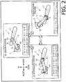
Fig. 2 is a schematic diagram showing an HD2 located at a viewing position (A), an intermediate position (B), and a non-viewing position (C). -
Fig. 3 is a block diagram showing an electrical configuration of theHMD 1. -
Fig. 4 shows timing charts for a field sequential method (A) and an alternative method (B). -
Fig. 5 is a flow chart of a main process. -
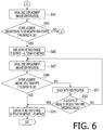
Fig. 6 is a flow chart of the main process and is a continuation ofFig. 5 . -
Fig. 7 shows timing charts for a field sequential method (A) and an alternative method (B) of the first modification. -
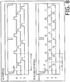
Fig. 8 shows timing charts for a field sequential method (A) and an alternative method (B) of the second modification. -
Fig. 9 is a schematic diagram showing the HD2 located at the viewing position (A), the intermediate position (B), and the non-viewing position (C). - An embodiment of the present disclosures will be described. As shown
Fig. 1 , a head-mounted display (hereinafter, referred to as an "HMD") 1 is a video transmission type HMD. TheHMD 1 includes a mountingfixture 11, aconnection fixture 12 and a display device 2 (hereinafter, referred to as an "HD 2"). Hereinafter, in order to facilitate understanding the description of the drawings, an upper side, a lower side, a left side, a right side, a front side and a rear side of theHMD 1 will be defined. The upper side, the lower side, the left side, the right side, the front side and the rear side of theHMD 1 correspond, for example, to an upper side, a lower side, a diagonally upper left side, a diagonally lower right side, a left side and a right side ofFig. 1 , respectively. The upper side, the lower side, the left side, the right side, the front side and the rear side of theHMD 1 correspond to an upper side, a lower side, a right side, a left side, a front side and a rear side of the user who wears the mountingfixture 11, respectively. - As shown in
Fig. 1 , the mountingfixture 11 is configured with flexible material such as resin or metal (e.g., stainless steel). The mountingfixture 11 has afirst section 11A andsecond sections 11B and 11C. In the following description, in order to facilitate understanding, the mountingfixture 11 will be described by dividing the same into thefirst section 11A and thesecond sections 11B and 11C. However, the mountingfixture 11 is not separated into members of thefirst section 11A and thesecond sections 11B and 11C, but is an integral member as a whole. - Each of the
first section 11A and thesecond sections 11B and 11C is a curved and elongated plate-shaped member. Thefirst section 11A is a part of the mountingfixture 11 extending in the right-left direction between aposition 112 and aposition 113. Thefirst section 11A is convexly curved forward. Theposition 112 is located on the left side with respect to thecenter 111 of the mountingfixture 11 in the right-left direction. Theposition 113 is located on the right side with respect to thecenter 111 of the mountingfixture 11 in the right-left direction. Thesecond section 11B is a part of the mountingfixture 11 extending rearward from theposition 112. The second section 11C is a part of the mountingfixture 11 extending rearward from theposition 113. Thesecond sections 11B and 11C extend in a direction where rear ends thereof approach each other. The mountingfixture 11 is worn on the head of the user in a state where thefirst section 11A and thesecond sections 11B and 11C contact a frontal region, a right temporal region and a left temporal region of the user, respectively. - The
connection fixture 12 is a substantially rod-like member. Theconnection fixture 12 is configured with resin or metal. Theconnection fixture 12 extends in the up-down direction in the front view. An upper end of theconnection fixture 12 is connected to the mountingfixture 11 through a ball joint 13 and aconnection member 14. A lower end of theconnection fixture 12 is connected to theHD 2 through a ball joint 15. In a state where the mountingfixture 11 is worn on the head of the user, dieconnection fixture 12 allows theHD 2 to be located in front of a left eye of the user. - The
HD 2 includes achassis 21. Thechassis 21 has a hollow box shape. An opening is provided on the rear end part of thechassis 21. The opening is covered with a transparent plate-shaped member. Aliquid crystal panel 10B is accommodated inside thechassis 21. Theliquid crystal panel 10B can switch its displaying method to either of two methods (a field sequential method (hereinafter, referred to as an "FS method") or an alternative method) which will be described later. Theliquid crystal panel 10B is electrically connected to an external device 9 (seeFig. 3 ) through a cable 10C. The external device 9 is, for example, a control box which executes control for making theliquid crystal panel 10B display an image. Theliquid crystal panel 10B displays an image on a displaying surface based on an image signal received from the external device 9 through the cable 10C. The displaying surface faces rearward. Image light of the image displayed on the displaying surface of theliquid crystal panel 10B is emitted rearward. The image light passes through the opening on the rear end part of thechassis 21 from the front side toward the rear side, and further passes through the transparent plate-shaped member toward the rear side. The image light is emitted toward the rear side of thechassis 21. - A specific example of usage of the
HMD 1 will be described. The user fixes the mountingfixture 11 of theHMD 1 on his/her head. The user holds theconnection fixture 12 and theHD 2 and adjusts positions thereof so that the opening on the rear end part of theHD 2 is located in front of the left eye to face the same. At this stage, the ball joints 13 and 15 enable theHD 2 to be located, with respect to the mountingfixture 11, at an appropriate position. Hereinafter, the position of theHD 2 when the opening on the rear end part of theHD 2 is located in front of the left eye to face the same will be referred to as a "viewing position." - A signal is output from the external device 9 to the
liquid crystal panel 10B of theHD 2 through the cable 10C. An image is displayed on the displaying surface of theliquid crystal panel 10B. Image light of the displayed image is emitted rearward toward the opening of thechassis 21. The image light is emitted to the outside of thechassis 21 after passing through the opening rearward and further passing through the transparent plate-shaped member rearward. The emitted image light is incident on the left eye of the user when theHD 2 is located at the viewing position. The user thereby recognizes the image. - As shown in
Fig. 2(A) , in a state where theHD 2 is located at the viewing position, theconnection fixture 12 extends downward from the mountingfixture 11. When theHMD 1 is viewed from the right side, an obtuse angle between respective extending directions of the mountingfixture 11 and the connection fixture 12 (hereinafter, referred to as a "first angle A1") takes one of the values within a range of angles when theconnection fixture 12 is rotated in both rotating directions (clockwise direction and anti-clockwise direction) by a predetermined range Δθ1 with a predetermined angle θ11 at the center ((θ11 - Δθ1) < A1 < (θ11 + Δθ1)). An acute angle between respective extending directions of theconnection fixture 12 and an image light emitting direction (hereinafter, referred to as a "second angle A2") takes one of the values within a range of angles when theHD 2 is rotated in both rotating directions by a predetermined range Δθ2 with a predetermined angle θ21 at the center ((θ21 - Δθ2) < A2 < (θ21 + Δθ2)). That is, when the first angle A1 satisfies the above-described condition ((θ11 - Δθ1) < A1 < (θ11 + Δθ1), which will be hereinafter referred to as a "first condition") and the second angle A2 satisfies the above-described condition ((θ21 - Δθ2) < A2 < (θ21 + Δθ2), which will be hereinafter referred to as a "second condition"), the image light emitted from theHD 2 can be incident on and can be visually recognized by the left eye of the user. Further, positions of theHD 2 of which the first angle A1 and the second angle A2 satisfy the above-described conditions correspond to the viewing position. - It is noted that, hereinafter, when rotating directions are described, unless otherwise specified, rotating directions (clockwise direction or anti-clockwise direction) are defined on the premise that the
HMD 1 is viewed from the right side. - On the other hand, there is a case where the user uses the
HMD 1 while locating theHD 2 such that both an image displayed on theliquid crystal panel 10B of theHD 2 and a scenery in front of the eyes of the user can be visually recognized. Hereinafter, a position of theHD 2 when theHMD 1 is used in such a state will be referred to as an "intermediate position." As shown inFig. 2(B) , the user displaces theHD 2 to the intermediate position by rotating theconnection fixture 12 and theHD 2 from the viewing position in the clockwise direction. In a state where theHD 2 is located at the intermediate position, theconnection fixture 12 extends downward from the mountingfixture 11. The first angle A1 takes one of the values within a range of angles when theconnection fixture 12 is rotated in both rotating directions by a range Δθ1 with a predetermined angle θ12, which is greater than the angle θ11 (θ11 < θ12), at the center ((θ12 - Δθ1) < A1 < (θ12 + Δθ1)). The second angle A2 takes one of the values within a range of angles when theHD 2 is rotated in both rotating directions by a range Δθ2 with a predetermined angle θ22, which is smaller than the angle θ21 (θ21 > θ22), at the center ((θ22 - Δθ2) < A2 < (θ22 + Δθ2)). That is, when the first angle A1 satisfies the above-described condition (((θ12 - Δθ1) < A1 < (θ12 + Δθ1), which will be hereinafter referred to as a "third condition") and the second angle A2 satisfies the above-described condition ((θ22 - Δθ2) < A2 < (θ22 + Δθ2), which will be hereinafter referred to as a "fourth condition"), the user can visually recognize both the image displayed on theliquid crystal panel 10B of theHD 2 and the scenery in front of the eyes of the user. Further, positions of theHD 2 of which the first angle A1 and the second angle A2 satisfy the above-described conditions correspond to the intermediate position. - On the other hand, there is a case where the user uses the
HMD 1 while locating theHD 2 out of the user's view such that the scenery in front of the eyes of the user can be visually recognized well. Hereinafter, a position of theHD 2 when theHMD 1 is used in such a state will be referred to as a "non-viewing position." As shown inFig. 2(C) , the user displaces theHD 2 to the non-viewing position by rotating theconnection fixture 12 from the viewing position in the clockwise direction. In a state where theHD 2 is located at the non-viewing position, theconnection fixture 12 extends upward from the mountingfixture 11. The first angle A1 takes one of the values within a range of angles when theconnection fixture 12 is rotated in both rotating directions by a range Δθ1 with a predetermined angle θ13, which is greater than the angles θ11 and θ12 (θ11 < θ12 < θ13), at the center ((θ13 - Δθ1) < A1 < (θ13 + Δθ1)). That is, when the first angle A1 satisfies the above-described condition (((θ13 - Δθ1) < A1 < (θ13 + Δθ1), which will be hereinafter referred to as a "fifth condition"), the user can visually recognize the scenery in front of the eyes of the user while suppressing theHD 2 from entering the user's view. Further, positions of theHD 2 of which the first angle A1 satisfies the above-described condition correspond to the non-viewing position. - Electrical configurations of the HMD 1 (the mounting
fixture 11 and the HD 2) will be described with reference toFig. 3 . The mountingfixture 11 includes anacceleration sensor 41. Theacceleration sensor 41 is electrically connected to an FPGA33 (which will be described later) of the HD2. Theacceleration sensor 41 detects accelerations respectively acting on the mountingfixture 11 in three axis directions (an X-axis direction, a Y axis direction and a Z-axis direction). Theacceleration sensor 41 outputs signals indicating the detected accelerations to theFPGA 33. - The HD2 has a
CPU 31, amemory 32, aliquid crystal panel 10B, FPGAs 33-36,acceleration sensors camera 39. TheCPU 31 controls theentire HMD 1. Thememory 32, theliquid crystal panel 10B, theFPGAs acceleration sensor 38 are electrically connected to theCPU 31. Theacceleration sensor 37 is electrically connected to theFPGA 33. Thecamera 39 is electrically connected to theFPGA 34. TheFPGA 35 is electrically connected to theFPGA 36. To thememory 32, a program of a main process (seeFig. 5 ) to be executed by theCPU 31, various parameters and the like are stored. It is noted that theHMD 1 may have one FPGA, having all the functions of the FPGAs 33-36, in place of the FPGAs 33-36. - The
acceleration sensor 37 detects accelerations respectively acting on theHD 2 in the three axis directions. Theacceleration sensor 37 outputs signals indicating the detected accelerations to theFPGA 33. TheFPGA 33 is a programmable logic device (hereinafter, referred to as a "PLD") including a function for detecting a position of theHD 2 with respect to the mountingfixture 11. TheFPGA 33 identifies an acceleration acting on theHD 2 based on the signals output from the acceleration sensor. TheFPGA 33 identifies an acceleration acting on the mountingfixture 11 based on the signals output from theacceleration sensor 41. TheFPGA 33 detects the position of theHD 2 with respect to the mountingfixture 11 by calculating a difference between the acceleration of theHD 2 and the acceleration of the mountingfixture 11. TheFPGA 33 outputs a signal indicating the detected position of theHD 2 to theCPU 31. - The
camera 39 is provided on the rear end part of the chassis 21 (seeFig. 1 ) of thedisplay device 2, and is capable of photographing a rear side of thechassis 21. Thecamera 39 outputs data of a photographed image to theFPGA 34. TheFPGA 34 is a PLD including a function of detecting a visual line direction of the user. A method of identifying the visual line direction by theFPGA 34 is as follows. TheFPGA 34 identifies, from an image based on the data output from thecamera 39, an inner corner of the eye of the user as a reference point, and an iris of the eye of the user as a moving point. TheFPGA 34 identifies the visual line direction of the user from a position of the iris with respect to the identified position of the inner corner of the eye. TheFPGA 34 further detects a displacement amount of the visual line based on a chronological change of the identified visual line direction. TheFPGA 34 outputs a signal indicating the detected displacement amount of the visual line to theCPU 31. - Similarly to the
acceleration sensor 37, theacceleration sensor 38 detects the accelerations respectively acting on theHD 2 in the three axis directions. Theacceleration sensor 38 outputs signals indicating the detected accelerations to theCPU 31. - The
FPGA 35 is a PLD having a function of analyzing colors of pixels. TheFPGA 35 detects, through the cable 10C, an image signal sent from the external device 9. TheFPGA 35 analyses a color of each of a plurality of pixels configuring an image based on the detected signal. TheFPGA 35 outputs a signal indicating an analysis result to theFPGA 36. TheFPGA 36 is a PLD having a function of detecting a ratio of areas having a specific color among the entire area of an image. TheFPGA 36 detects a ratio of areas having black color among the entire area of an image to be displayed on theliquid crystal panel 10B based on the signal output from theFPGA 35. TheFPGA 36 outputs a signal indicating the detected ratio to theCPU 31. - The
liquid crystal panel 10B switches a displaying method to one of two methods (the FS method or the alternative method) based on the signal output from theCPU 31. Theliquid crystal panel 10B displays an image on the displaying surface, with a displaying method according to the signal output from theCPU 31, based on the image signal output from the external device 9. - Two displaying method in which the
liquid crystal panel 10B of theHD 2 can display will be described with reference toFig. 4 . The first method is the FS method. The FS method is a method which makes the user recognize a color image by outputting lights of red (R), green (G) and blue (B) while switching them in a time division.Fig. 4(A) illustrates a timing chart of a vertical synchronizing signal (Vsync) and respective output signals of RGB lights, in a case where a white image is displayed on theliquid crystal panel 10B in the FS method. As shown inFig. 4(A) , in the FS method, the RGB lights are output synchronously with the vertical synchronizing signal (Vsync) while switching the RGB lights in a first cycle T1. It is noted that the RGB lights are arranged with time lag such that the RGB lights are output at different timings. An output duration of light at each timing is t1. - The second method is the alternative method. The alternative method is a method which makes the user recognize an image by outputting one of the RGB lights which are output in the FS method at the same timing as the FS method.
Fig .4(B) illustrates a timing chart of a vertical synchronizing signal (Vsync) and output respective signals of the RGB lights, in a case where the FS method shown inFig. 4(A) is switched to the alternative method in which only the green (G) light is output. As shown inFig. 4(B) , in the alternative method, one of the RGB lights (in the case shown inFig. 4(B) , the B light) is output in the first cycle T1. In this case, the white image in the FS method (Fig. 4(A) ) is converted to a monochromatic (green) image by switching to the alternative method. The output duration t1 of light at each timing is the same as that in the FS method. - The main process to be executed by the
CPU 31 will be described with reference toFig. 5 andFig. 6 . The main process starts by theCPU 31 executing the program stored in thememory 32 when output of the image signal from the external device 9 is started. As Shown inFig. 5 , theCPU 31 outputs, to theliquid crystal panel 10B, a signal for making theliquid crystal panel 10B to display an image in the FS method (S11). Theliquid crystal panel 10B displays an image on the displaying surface in the FS method based on the signal output from the external device 9. - The
CPU 31 identifies the acceleration acting on theHD 2 based on the signals output from theacceleration sensor 38. TheCPU 31 determines whether the identified acceleration is equal to or greater than a predetermined first threshold value Th1 or not (S13). If it is determined that the acceleration acting on theHD 2 is less than the first threshold value Th1 (S13: NO), theCPU 31 returns to the process S11. TheCPU 31 continues to output, to theliquid crystal panel 10B, the signal for making theliquid crystal panel 10B to display an image in the FS method (S11). Therefore, on theliquid crystal panel 10B, when the acceleration acting on theHD 2 is less than the first threshold value Th1, an image is displayed in the FS method. On the other hand, when it is determined that the acceleration acting on theHD 2 is equal to or greater than the first threshold value Th1 (S13: YES), theCPU 31 proceeds to process S15. - The
CPU 31 identifies a ratio of areas having black color among the entire area of an image displayed on theliquid crystal panel 10B based on the signal output from die FPGA 36 (S15). TheCPU 31 determines whether the identified ratio is equal to or greater than a predetermined threshold value Th2 or not (S17). If it is determined that the ratio of areas having black color is less than the second threshold value Th2 (S17: NO), theCPU 31 returns to the process S11. Therefore, on theliquid crystal panel 10B, when the ratio of areas having black color among the entire area of the image is less than the second threshold value Th2, the image is displayed in the FS method. On the other hand, when it is determined that the ratio of areas having black color is equal to or greater than the second threshold value Th2 (S17: YES), theCPU 31 proceeds to process S19. - The
CPU 31 identifies the position of theHD 2 with respect to the mountingfixture 11 based on the signal output from the FPGA 33 (S19). TheCPU 31 determines whether theHD 2 is located at the intermediate position (SeeFig. 2(B) .) or not based on the identified position of the HD 2 (S21). If theHD 2 is located at a position that satisfies the third condition and the fourth condition (SeeFig. 2(B) .), TheCPU 31 determines that theHD 2 is located at the intermediate position (S21: YES). In this case, theCPU 31 outputs, to theliquid crystal panel 10B, a signal for making theliquid crystal panel 10B to display an image in the alternative method (S23). The displaying method of theliquid crystal panel 10B changes from the FS method to the alternative method. Theliquid crystal panel 10B displays an image on the displaying surface in the alternative method based on the signal output from the external device 9. TheCPU 31 proceeds to process S25. - The
CPU 31 identifies the position of theHD 2 with respect to the mountingfixture 11 based on the signal output from the FPGA 33 (S25). TheCPU 31 determines whether theHD 2 is located at the non-viewing position (SeeFig. 2(C) .) or not based on the identified position of the HD 2 (S27). If theHD 2 is located at a position that satisfies the fifth condition (SeeFig. 2(C) .), theCPU 31 determines that theHD 2 is located at the non-viewing position (S27: YES). In this case, theCPU 31 specifies the displaying method of theliquid crystal panel 10B as the FS method, and proceeds to process S35. On the other hand, if theHD 2 is not located at a position that satisfies the fifth condition and it is determined that theHD 2 is not located at the non-viewing position (S27: NO), theCPU 31 proceeds to process S29. TheCPU 31 determines whether theHD 2 is located at the viewing position (SeeFig. 2(A) .) or not (S29). If theHD 2 is located at a position that satisfies the first condition and the second condition (SeeFig. 2(A) .), theCPU 31 determines that theHD 2 is located at the viewing position (S29: YES). In this case, theCPU 31 specifies the displaying method of theliquid crystal panel 10B as the FS method, and proceeds to process S35. - If it is determined that the
HD 2 is located at the non-viewing position or the viewing position, theCPU 31 outputs, to theliquid crystal panel 10B, the signal for making theliquid crystal panel 10B to display an image in the FS method (S35). The displaying method of theliquid crystal panel 10B changes from the alternative method to the FS method. Theliquid crystal panel 10B displays an image on the displaying surface in the FS method based on the signal output from the external device 9. TheCPU 31 terminates the main process. - If it is determined that the
HD 2 is not located at the viewing position (S29: NO), theCPU 31 identifies the ratio of areas having black color among the entire area of an image displayed on theliquid crystal panel 10B based on the signal output from the FPGA 36 (S31). TheCPU 31 determines whether the identified ratio is equal to or less than a predetermined third threshold value Th3 smaller than the second threshold value Th2 (Th2 > Th3) or not (S33). If it is determined that the ratio of areas having black color is greater than the third threshold value (S33: NO), theCPU 31 specifies the displaying method of theliquid crystal panel 10B as the alternative method, and returns to the process S25. In this case, theliquid crystal panel 10B continues to display the image in the alternative method. TheCPU 31 repeats the processes S25-S33. - If it is determined that the ratio of areas having black color is equal to or less than the third threshold value Th3 (S33: YES), the
CPU 31 proceeds to process S35. TheCPU 31 outputs, to theliquid crystal panel 10B, the signal for making theliquid crystal panel 10B to display an image in the FS method (S35). The displaying method of theliquid crystal panel 10B changes from the alternative method to the FS method. Theliquid crystal panel 10B displays the image on the displaying surface in the FS method based on the signal output from the external device 9. TheCPU 31 terminates the main process. - On the other hand, if the
HD 2 is not located at aposition that satisfies the third condition and the fourth condition (SeeFig. 2(B) .) and it is determined that theHD 2 is not located at the intermediate position (S21: NO), theCPU 31 proceeds to process S41 (SeeFig. 6 .). As shown inFig. 6 , theCPU 31 identifies the displacement amount of the visual line of the user based on the signal output from the FPGA 34 (S41). TheCPU 31 determines whether the identified displacement amount of the visual line is equal to or greater than a predetermined fourth threshold value Th4 (S43). If it is determined that the displacement amount of the visual line is less than the fourth threshold value Th4 (S43: NO), theCPU 31 returns to the process S11 (SeeFig. 5 .). In this case, theliquid crystal panel 10B continues to display an image in the FS method (See S11.). - If it is determined that the displacement amount of the visual line is equal to or greater than the fourth threshold value Th4 (S43: YES), the
CPU 31 outputs, to theliquid crystal panel 10B, the signal for making theliquid crystal panel 10B to display an image in the alternative method (S45). The displaying method of theliquid crystal panel 10B changes from the FS method to the alternative method. Theliquid crystal panel 10B displays an image on the displaying surface in the alternative method based on the signal output from the external device 9. TheCPU 31 proceeds to process S47. - The
CPU 31 identifies the displacement amount of the visual line of the user based on the signal output from the FPGA 34 (S47). TheCPU 31 determines whether the identified displacement amount of the visual line is less than a predetermined fifth threshold value Th5 smaller than the fourth threshold value Th4 (Th4 > Th5) or not (S49). If it is determined that the displacement amount of the visual line is less than the fifth threshold value Th5 (S49: YES), dieCPU 31 proceeds to the process S55. TheCPU 31 outputs, to theliquid crystal panel 10B, the signal for making theliquid crystal panel 10B to display an image in the FS method (S55). The displaying method of theliquid crystal panel 10B changes from the alternative method to the FS method. Theliquid crystal panel 10B displays an image on the displaying surface in the FS method based on the signal output from the external device 9. TheCPU 31 terminates the main process. - If it is determined that the displacement amount of the visual line is equal to or greater than the fifth threshold value Th5 (S49: NO), the
CPU 31 proceeds to process S51. TheCPU 31 identifies the ratio of areas having black color among the entire area of an image displayed on theliquid crystal panel 10B based on the signal output from the FPGA 36 (S51). TheCPU 31 determines whether the identified ratio is equal to or less than the third threshold value Th3 or not (S53). If it is determined that the ratio of areas having black color is greater than the third threshold value Th3 (S53: NO), theCPU 31 returns to the process S47. In this case, theliquid crystal panel 10B continues to display the image in the alternative method. TheCPU 31 repeats the processes S49-S53. - If it is determined that the ratio of areas having black color is equal to or less than the third threshold value Th3 (S53: YES), the
CPU 31 proceeds to process S55. TheCPU 31 outputs, to theliquid crystal panel 10B, the signal for making theliquid crystal panel 10B to display an image in the FS method (S55). The displaying method of theliquid crystal panel 10B changes from the alternative method to the FS method. Theliquid crystal panel 10B displays the image on the displaying surface in the FS method based on the signal output from the external device 9. TheCPU 31 terminates the main process. - In a case where an image is displayed on the
liquid crystal panel 10B in the FS method, the color breaking is likely to occur when thedisplay device 2 moves. On the other hand, if an image is displayed on theliquid crystal panel 10B in the alternative method, the color breaking does not occur even when thedisplay device 2 moves. In this regard, in theHMD 1, if the acceleration acting on thedisplay device 2 is less than the first threshold value Th1 (S13: NO), an image is displayed on theliquid crystal panel 10B in the FS method (S11), and if the acceleration acting on thedisplay device 2 is equal to or greater than the first threshold value Th1 (S13: YES), an image is displayed on theliquid crystal panel 10B in the alternative method (S23, S45). Therefore, theHMD 1 can control the displaying while taking advantage of features of the FS method (e.g., a resolution enhancement becomes possible) by displaying an image on theliquid crystal panel 10B in the FS method when the color breaking is less likely to occur. On the other hand, theHMD 1 can prevent the occurrence of the color breaking by displaying an image on theliquid crystal panel 10B in the alternative method when the color breaking is likely to occur. Accordingly, theHMD 1 can suppress a degradation of a visibility for the user due to the occurrence of the color breaking. It is noted that the case where the color breaking is less likely to occur is, for example, when the acceleration acting on thedisplay device 2 is small. The case where the color breaking is likely to occur is, for example, when the acceleration acting on thedisplay device 2 is large. - In a case where an image is displayed on the
liquid crystal panel 10B in the FS method, the color breaking is more likely to occur especially when the image is closer to a black-and-white image. It is noted that, if the ratio of areas having black color to the entire area of the image is equal to or greater than the second threshold value, the image is close to a black-and-white image. In this regard, in theHMD 1, if the acceleration action on thedisplay device 2 is equal to or greater than the first threshold value Th1 (S13: YES) and the ratio of black color is equal to or greater than the second threshold value Th2 (S17: YES), the image is displayed on theliquid crystal panel 10B in the alternative method (S23). By this configuration, since theHMD 1 displays an image on theliquid crystal panel 10B in the alternative method in a state where the color breaking is more likely to occur, the color breaking can be suppressed effectively. - After the ratio of black color became equal to or greater than the second threshold value Th2 (S17: YES), if the ratio of black color has decreased up to a value equal to or less than the third threshold value Th3 (S33: YES), the image has changed to the one closer to a color image and therefore it is likely that the color breaking has become less likely to occur. Therefore, if the ratio of black color has become equal to or less than the third threshold value Th3 (S33: YES), the
HMD 1 displays the image on theliquid crystal panel 10B in the FS method (S35). By this configuration, theHMD 1 can display an image in a high resolution in the FS method while preventing the occurrence of the color breaking. Also, the user needs not manually perform an operation for restoring the display method to the FS method after the display method is switched from the FS method to the alternative method. Therefore, theHMD 1 can enhance the convenience for the user. It is noted that, by setting the third threshold value Th3 to be smaller than the second threshold value Th2, theHMD 1 can suppress the display method of theliquid crystal panel 10B from restoring from the alternative method to the FS method immediately after the display method has switched from the FS method to the alternative method. - When the
HD 2 is located at the intermediate position, it is likely that the user is intending to visually recognize both an image displayed on theliquid crystal panel 10B and a scenery in front of the eyes of the user. In this case, since the user will move his/her eye to visually recognize both of them, the displacement amount of the visual line will become greater. It is noted that, if an image is displayed in the FS method, the color breaking becomes more likely to occur as the displacement amount of the visual line becomes greater. In this regard, if theHD 2 is located at the intermediate position (S21: YES), theHMD 1 switches the display method of theliquid crystal panel 10B from the FS method to the alternative method, and displays an image in the alternative method (S23). By this configuration, theHMD 1 can effectively suppress the color breaking in the situation where the color breaking is likely to occur. - When the
HD 2 is located at the non-viewing position, it is likely that the user is not viewing an image displayed on theliquid crystal panel 10B. Therefore, if theHD 2 is located at the non-viewing position (S27: YES), theHMD 1 displays an image on theliquid crystal panel 10B in the FS method (S35). By this configuration, if, for example, the location of theHD 2 is changed from the non-viewing position to the viewing position, thereby becoming in a situation where the user visually recognizes an image displayed on theliquid crystal panel 10B again, since theliquid crystal panel 10B is in a state where an image is displayed in the FS method, theHMD 1 can make the user visually recognize an image of high image quality. - When the
HD 2 is located at the viewing position, since it is likely that the user is directly viewing an image displayed on theliquid crystal panel 10B, it is likely that the displacement amount of the visual line of the user is small. Therefore, even if an image is displayed on theliquid crystal panel 10B in the FS method, the color breaking is less likely to occur. Accordingly, if theHD 2 is located at the viewing position (S29: YES), theHMD 1 displays an image in the FS method (35). By this configuration, theHMD 1 can make the user visually recognize an image of high image quality in the situation where the color breaking is less likely to occur. - When an image is displayed on the
liquid crystal panel 10B in the FS method, the color breaking is likely to occur if the displacement amount of the visual line of the user is large. In this regard, in theHMD 1, if the displacement amount of the visual line is equal to or greater than the fourth threshold value Th4 (S43: YES), an image is displayed on theliquid crystal panel 10B in the alternative method (S45). By this configuration, theHMD 1 can effectively suppress the color breaking in the situation where the color breaking is likely to occur. - On the other hand, even when an image is displayed on the
liquid crystal panel 10B in the FS method, if the displacement amount of the visual line is small, the color breaking is less likely to occur. Therefore, when the displacement amount of the visual line is less than the fifth threshold value Th5 (S49: YES), theHMD 1 displays an image in the FS method (S55). By this configuration, theHMD 1 can make the user visually recognize an image of high image quality in the situation where the color breaking is less likely to occur. It is noted that, by setting the fifth threshold value Th5 to be smaller than the fourth threshold value Th4, theHMD 1 can suppress the display method of theliquid crystal panel 10B from restoring from the alternative method to the FS method immediately after the display method has switched from the FS method to the alternative method. - The FS method is a method which makes the user visually recognize a color image by outputting the RGB lights while switching them in a time division. On the other hand, the alternative method is a method in which, by outputting one of the RGB lights which are output in the FS method at the same timing as the FS method, the user visually recognizes a monochromatic image. It is noted that the color breaking occurs when images of respective colors of RGB are visually recognized as after images or the like. Accordingly, since the
HMD 1 makes the user visually recognize a monochromatic image by displaying an image on theliquid crystal panel 10B in the alternative method, the occurrence of the color breaking can be suppressed. Also, theHMD 1 can suppress a total output amount of the lights by displaying an image on theliquid crystal panel 10B in the alternative method. Therefore, theHMD 1 can suppress power consumption as compared to the case where an image is displayed on theliquid crystal panel 10B in the FS method by displaying an image on theliquid crystal panel 10B in the alternative method. - The alternative method in the above-described embodiment may be changed to other methods. As shown in
Fig. 7 , the alternative method of the first variation is a method which makes the user visually recognize an image by outputting all the RGB lights at the same timing.Fig. 7(B) illustrates a timing chart of a vertical synchronizing signal (Vsync) and output respective signals of the RGB lights in a case where the FS method shown inFig. 7(A) is switched to the alternative method. As shown inFig. 7(B) , in the alternative method of the first variation, all the RGB lights are output synchronously in the first cycle T1. In this case, images in the FS method ofFig. (7 ), having colors other than white (e.g., the RGB colors), are all converted to white images by switching to the alternative method. The output duration t1 of light at each timing is the same as that in the FS method. - The
HMD 1 can suppress the occurrence of the color breaking by displaying an image on theliquid crystal panel 10B in the alternative method. This is because, the color breaking occurs due to the RGB lights being output at different timings, whereas, in the alternative method, the RGB lights are output at the same timing. Also, if an image is displayed on theliquid crystal panel 10B in the alternative method, images of respective colors of RGB in the FS method are all displayed as white images. That is, the original color image is converted to a black-and-white image as the FS method is switched to the alternative method. In contrast, in the above-described embodiment, an image in the FS method is converted to a monochromatic image (SeeFig. 4 .). Therefore, theHMD 1 can display an image on theliquid crystal panel 10B while maintaining a display mode of the original image whenever possible as compared to the alternative method of the above-described embodiment. - As shown in
Fig. 8 , the alternative method of the second variation is a method which makes the user visually recognize an image by outputting the RGB lights while switching them in a second cycle T2 which is half the first cycle T1.Fig. 8(B) illustrates a timing chart of a vertical synchronizing signal (Vsync) and respective output signals of the RGB lights in a case where the FS method shown inFig. 8(A) is switched to the alternative method. As with the FS method, the RGB lights are arranged with time lag such that the RGB lights are output at different timings. Also, in the alternative method, an output duration t2 of the light is one half of the output duration t1 of the FS method. That is, in the alternative method, the number of outputs of each of the RGB lights becomes twice the number of that in the FS method (first cycle T1 → second cycle T2), and the output duration of light becomes one half of that in the FS method (output duration t1 → output duration t2). Therefore, the total of respective output durations of the RGB lights becomes the same as that in the case of the FS method. - The
HMD 1 can suppress the occurrence of the color breaking by displaying an image on theliquid crystal panel 10B in the alternative method. This is because the color breaking is caused by images of respective colors of RGB not being well mixed when they are visually recognized by the user, whereas, by displaying in the alternative method, the RGB lights are output while being switched in the second cycle T2 being shorter than that of the FS method, and therefore is more likely that the RGB lights are properly mixed by the afterimage effect. Furthermore, the images of respective colors of RGB in the FS method are similarly reproduced in the image displayed in the alternative method. Therefore, theHMD 1 can appropriately reproduce a display mode of the original image even in the case where the image is displayed on theliquid crystal panel 10B in the alternative method. - The present disclosures are not limited to the above-described embodiment, and various modifications are possible. The
CPU 31 identifies the acceleration acting on theHD 2 based on the signals output from theacceleration sensor 38. However, theCPU 31 may identify the accelerations respectively acting on the mountingfixture 11 and theHD 2 based on the signals output from theacceleration sensor 41 provided to the mountingfixture 11 and the signals output from theacceleration sensor 38 provided to theHD 2. TheCPU 31 may calculate an acceleration of a relative movement of theHD 2 with respect to the mountingfixture 11 from the identified respective accelerations of theHD 2 and the mountingfixture 11. If the calculated acceleration is less than the first threshold value Th1 (S13: NO), theCPU 31 may display an image on theliquid crystal panel 10B in the FS method. On the other hand, if the calculated acceleration is equal to or greater than the first threshold value Th1 (S13: YES), theCPU 31 may display an image on theliquid crystal panel 10B in the alternative method (S23). - The
FPGA 36 may detect whether an image is a black-and-white image or a color image based on the signal output from theFPGA 35, and may output a signal indicating the detection result to theCPU 31. If it is determined, based on the signal output from theFPGA 36, that the image is a color image, theCPU 31 may display the image on theliquid crystal panel 10B in the FS method (S11). On the other hand, if it is determined that the image is a black-and-white image, theCPU 31 may display the image on theliquid crystal panel 10B in the alternative method (S23). - If it is determined that the ratio of areas having black color equal to or greater than the second threshold value Th2 (S33: YES), the
CPU 31 may output, to theliquid crystal panel 10B, the signal for making theliquid crystal panel 10B display an image in the FS method (S35). That is, theCPU 31 may make a threshold value for determining whether to switch the displaying method from the FS method to the alternative method (the second threshold value Th2) and a threshold value for determining whether to switch the displaying method from the alternative method to the FS method (the third threshold value Th3) the same. - The intermediate position and the non-viewing position of the
HD 2 are not limited to the cases defined by the third to fifth conditions (SeeFig. 2 .). Specific examples are as follows. As shown inFig. 9(A) , a position of theHD 2 at which a direction of image light emitted from theHD 2 faces rearward is defined as the viewing position, and the image light emitting direction in this case is defined as a "reference direction." Also, an angle between the emitting direction of the image light and the reference direction in a case where, when viewed from above, theHD 2 rotates counterclockwise from the viewing position is defined as a "third angle A3." The image light emitting direction faces obliquely rearward left (obliquely rearward right when viewed by the user). As shown inFig. 9(B) , theCPU 31 may determine that the position of theHD 2 is located at the intermediate position when theHD 2 is located at a position that satisfies a condition that the third angle A3 is greater than a predetermined angle θa and is smaller than a predetermined angle θb (θa < A3 < θb). Also, as shown inFig. 9(C) , theCPU 31 may determine that theHD 2 is located at the non-viewing position when theHD 2 is located at a position that satisfies a condition that the third angle A3 is greater than the angle θb (θb < A3). - The position of the
HD 2 with respect to the mountingfixture 11 may be identified with methods other than the above-described one. For example, a camera capable of photographing the mountingfixture 11 may be provided to theHD 2. TheCPU 31 may identify the positon of theHD 2 with respect to the mountingfixture 11 by analyzing the image photographed by the camera and thereby identifying the position of the mountingfixture 11. - If it is determined that the acceleration acting on the
HD 2 is equal to or greater than the first threshold value Th1 (S13: YES), theCPU 31 may always display an image on theliquid crystal panel 10B in the alternative method (S23) regardless of the ratio of black color among the entire area of an image and/or the position of theHD 2 with respect to the mountingfixture 11. - If it is determined that the
HD 2 is located at the viewing position (S29: YES), theCPU 31 may switch the displaying method of theliquid crystal panel 10B from the alternative method to the FS method, and if it is determined that theHD 2 is located at the non-viewing position (S27: YES), theCPU 31 may not switch the displaying method of theliquid crystal panel 10B and may keep the alternative method. TheCPU 31 may identify an acceleration of the displacement of the visual line based on the signal output from the FPGA 34 (S41). If the identified acceleration is equal to or greater than a predetermined threshold value (S43: YES), theCPU 31 may display an image on theliquid crystal panel 10B in the alternative method (S45). - In executing the processes S27 and S29, the
CPU 31 may make the determination based on the displacement amount of the visual line in place of the determination based on the position of theHD 2. That is, if the displacement amount of the visual line of the user is less than a predetermined threshold value (S27: YES, S29: YES), theCPU 31 may display an image on theliquid crystal panel 10B in the FS method. - In the above-described embodiment, the
CPU 31 identifies the acceleration acting on theHD 2 based on the signals output from theacceleration sensor 38, and if it is determined that the identified acceleration is equal to or greater than the predetermined first threshold value Th1 (S13: YES), theCPU 31 changes the display method from the FS method to the alternative method. However, theCPU 31 may identify a parameter indicating an amount of movement of theHD 2 based on the signals output from theacceleration sensor 38. Examples of the parameter indicating the amount of movement include a displacement amount, a displacement velocity or the like of theHD 2. If it is determined that the identified parameter is equal to or greater than a predetermined threshold value, theCPU 31 may change the displaying method from the FS method to the alternative method. Also, for example, theHMD 1 may have a sensor (e.g., an angular velocity sensor or the like) capable of identifying the amount of movement of theHD 2 in place of theacceleration sensor 38. - The
liquid crystal panel 10B is an example of the "display element" of the present disclosures. TheHD 2 is an example of the "display part" of the present disclosures. Theacceleration sensor 38 is an example of the "first detecting means" of the present disclosures. TheFPGA 36 is an example of the "second detecting means" of the present disclosures. TheFPGA 33 is an example of the "third detecting means" of the present disclosures. TheFPGA 34 is an example of the "fourth detecting means" of the present disclosures. TheCPU 31 executing the process S11 is an example of the "first control means" of the present disclosures. TheCPU 31 executing the processes S23 and S45 is an example of the "second control means" of the present disclosures. TheCPU 31 executing the processes S35 and S55 is an example of the "third control means" of the present disclosures. TheCPU 31 executing the process S35 is an example of the "fourth control means" of the present disclosures. TheCPU 31 executing the process S55 is an example of the "fifth control means" of the present disclosures. -
- 1
- : HMD
- 2
- : display device
- 10B
- : liquid crystal panel
- 11
- : mounting fixture
- 12
- : connection fixture
- 31
- : CPU
- 33, 34, 35, 36
- : FPGA
- 37, 38, 41
- : acceleration sensor
- Th1
- : first threshold value
- Th2
- : second threshold value
- Th3
- : third threshold value
- Th4
- : fourth threshold value
- Th5
- : fifth threshold value
Claims (9)
- A head-mounted display, comprising:a display part having a display element configured to display an image;a mounting part for mounting the display part on a head of a user;a first detecting means configured to detect a movement of the display part;a first control means configured to make the display element display the image in a field sequential method if an amount of the movement detected by the first detecting means is less than a predetermined first threshold value; anda second control means configured to make the display element display the image in an alternative method different from the field sequential method if the amount of the movement detected by the first detecting means is equal to or greater than the first threshold value.
- The head-mounted display according to claim 1,
further comprising a second detecting means configured to detect a ratio of areas having black color among an entire area of the image displayed on the display element,
wherein if the amount of the movement detected by the first detecting means is equal to or greater than the first threshold value and the ratio detected by the second detecting means is equal to or greater than a predetermined second threshold value, the second control means makes the display element display the image in the alternative method. - The head-mounted display according to claim 2,
further comprising a third control means configured to make the display element display the image in the field sequential method if, after the image is displayed on the display element in the alternative method by the second control means, the ratio detected by the second detecting means becomes equal to or less than a third threshold value smaller than the second threshold value. - The head-mounted display according to any one of claims 1 to 3,
further comprising a third detecting means configured to detect a position of the display part with respect to the mounting part,
wherein the second control means specifies one of the field sequential method and the alternative method based on the position detected by the third detecting means and makes the display element display the image in the specified method. - The head-mounted display according to any one of claims 1 to 3,
further comprising a fourth detecting means configured to detect a displacement amount of a visual line of the user,
wherein if the displacement amount detected by the fourth detecting means is equal to or greater than a predetermined fourth threshold value, the second control means makes the display element display the image in the alternative method. - The head-mounted display according to claim 5,
further comprising a fifth control means configured to make the display element display the image in the field sequential method if, after the image is displayed on the display element in the alternative method by the second control means, the displacement amount detected by the fourth detecting means becomes less than a fifth threshold value smaller than the fourth threshold value. - The head-mounted display according to any one of claims 1 to 6,
wherein the field sequential method is a method in which RGB lights are output while being switched in a time division, and
wherein the alternative method is a method in which one of the RGB lights is output. - The head-mounted display according to any one of claims 1 to 6,
wherein the field sequential method is a method in which the RGB lights are output while being switched in a time division, and
wherein the alternative method is a method in which the RGB lights are output simultaneously. - A head-mounted display, comprising:a display part having a display element configured to display an image;a mounting part for mounting the display part on a user;a first detecting means configured to detect a movement of the display part;a first control means configured to make the display element display the image in a first method if an amount of the movement detected by the first detecting means is less than a predetermined first threshold value; anda second control means configured to make the display element display the image in a second method different from the first method if the amount of the movement detected by the first detecting means is equal to or greater than the first threshold value,wherein the first method is a method in which RGB lights are output while being switched in a time division in a first cycle, andwherein the second method is a method in which the RGB lights are output while being switched in a time division in a second cycle shorter than the first cycle.
Applications Claiming Priority (2)
| Application Number | Priority Date | Filing Date | Title |
|---|---|---|---|
| JP2016189137A JP2018054775A (en) | 2016-09-28 | 2016-09-28 | Head-mounted display |
| PCT/JP2017/025243 WO2018061401A1 (en) | 2016-09-28 | 2017-07-11 | Head-mounted display |
Publications (2)
| Publication Number | Publication Date |
|---|---|
| EP3522148A1 true EP3522148A1 (en) | 2019-08-07 |
| EP3522148A4 EP3522148A4 (en) | 2020-03-11 |
Family
ID=61762607
Family Applications (1)
| Application Number | Title | Priority Date | Filing Date |
|---|---|---|---|
| EP17855360.8A Withdrawn EP3522148A4 (en) | 2016-09-28 | 2017-07-11 | HEAD MOUNTED DISPLAY |
Country Status (4)
| Country | Link |
|---|---|
| US (1) | US20190027083A1 (en) |
| EP (1) | EP3522148A4 (en) |
| JP (1) | JP2018054775A (en) |
| WO (1) | WO2018061401A1 (en) |
Families Citing this family (3)
| Publication number | Priority date | Publication date | Assignee | Title |
|---|---|---|---|---|
| WO2021216082A1 (en) * | 2020-04-24 | 2021-10-28 | Hewlett-Packard Development Company, L.P. | Mechanical mount feature |
| JP2023150811A (en) * | 2022-03-31 | 2023-10-16 | シチズンファインデバイス株式会社 | image display device |
| CN121511486A (en) * | 2023-07-14 | 2026-02-10 | 株式会社迈格诺皓特 | Display devices and display systems |
Family Cites Families (13)
| Publication number | Priority date | Publication date | Assignee | Title |
|---|---|---|---|---|
| US5528262A (en) * | 1993-01-21 | 1996-06-18 | Fakespace, Inc. | Method for line field-sequential color video display |
| JP2003029720A (en) * | 2001-07-16 | 2003-01-31 | Fujitsu Ltd | Display device |
| JP2003271112A (en) * | 2002-03-19 | 2003-09-25 | Sharp Corp | Liquid crystal display |
| JP5000203B2 (en) * | 2006-06-13 | 2012-08-15 | シチズンホールディングス株式会社 | Color display device |
| KR20130014547A (en) * | 2010-03-09 | 2013-02-07 | 가부시키가이샤 에이치디티 | Color display device and method |
| WO2012099041A1 (en) * | 2011-01-20 | 2012-07-26 | シャープ株式会社 | Image display device and image display method |
| US20150316766A1 (en) * | 2012-03-23 | 2015-11-05 | Google Inc. | Enhancing Readability on Head-Mounted Display |
| JP6252031B2 (en) * | 2013-08-17 | 2017-12-27 | セイコーエプソン株式会社 | Electro-optical device drive device, electro-optical device drive method, electro-optical device, and electronic apparatus |
| US20160147063A1 (en) * | 2014-11-26 | 2016-05-26 | Osterhout Group, Inc. | See-through computer display systems |
| US9836122B2 (en) * | 2014-01-21 | 2017-12-05 | Osterhout Group, Inc. | Eye glint imaging in see-through computer display systems |
| JP6582374B2 (en) * | 2014-09-01 | 2019-10-02 | セイコーエプソン株式会社 | Display device, control method therefor, and computer program |
| GB201518112D0 (en) * | 2015-10-13 | 2015-11-25 | Bae Systems Plc | Improvements in and relating to displays |
| CN110574099B (en) * | 2017-05-01 | 2022-07-12 | 安波福技术有限公司 | Head tracking based field sequential saccadic separation reduction |
-
2016
- 2016-09-28 JP JP2016189137A patent/JP2018054775A/en active Pending
-
2017
- 2017-07-11 WO PCT/JP2017/025243 patent/WO2018061401A1/en not_active Ceased
- 2017-07-11 EP EP17855360.8A patent/EP3522148A4/en not_active Withdrawn
-
2018
- 2018-09-27 US US16/143,673 patent/US20190027083A1/en not_active Abandoned
Also Published As
| Publication number | Publication date |
|---|---|
| US20190027083A1 (en) | 2019-01-24 |
| WO2018061401A1 (en) | 2018-04-05 |
| JP2018054775A (en) | 2018-04-05 |
| EP3522148A4 (en) | 2020-03-11 |
Similar Documents
| Publication | Publication Date | Title |
|---|---|---|
| US9123179B2 (en) | Surrounding image display system and surrounding image display method for vehicle | |
| CN104715738B (en) | head-up display information display device and method | |
| EP2512133B1 (en) | Vehicle periphery image display system | |
| US20160363993A1 (en) | Transparent display system and apparatus provided with the same | |
| JP6669053B2 (en) | Head-up display system | |
| EP3242268A1 (en) | Method for automatically identifying and calibrating medical color and gray-scale images | |
| US20190027083A1 (en) | Head-Mounted Display | |
| US10085636B2 (en) | Eye gaze detection apparatus and eye gaze detection method | |
| JP4200343B2 (en) | Monitor device | |
| US11025836B2 (en) | Driving assistance device, driving assistance method, and driving assistance program | |
| JP2008158922A (en) | Wrinkle detection device, wrinkle detection method and program | |
| JP2012148710A (en) | Image display apparatus | |
| EP2476588A1 (en) | Vehicle surrounding monitor apparatus | |
| US11588976B2 (en) | Image capturing apparatus having image capturing device provided with polarization elements and method of controlling same | |
| KR20120036241A (en) | Camera for detecting driver's status | |
| CN104977716A (en) | Eyepiece-type display apparatus and display control method therefor | |
| JPH09101477A (en) | Information display device | |
| CN107836020A (en) | Image display device and control method | |
| CN115123068B (en) | Vehicle control device, vehicle, method for operating vehicle control device, and storage medium | |
| JP2019047296A (en) | Display device, display method, control program, and electronic mirror system | |
| JP2008017311A (en) | VEHICLE VIDEO DISPLAY DEVICE AND VEHICLE AROUND VIDEO DISPLAY METHOD | |
| CN110126740A (en) | A kind of control method and device of automotive electronics rearview mirror | |
| CN111071037A (en) | Device control method, device, vehicle head-up display device, and storage medium | |
| JP6540676B2 (en) | Head mounted display | |
| JP2004192345A (en) | Driver status detection device |
Legal Events
| Date | Code | Title | Description |
|---|---|---|---|
| STAA | Information on the status of an ep patent application or granted ep patent |
Free format text: STATUS: THE INTERNATIONAL PUBLICATION HAS BEEN MADE |
|
| PUAI | Public reference made under article 153(3) epc to a published international application that has entered the european phase |
Free format text: ORIGINAL CODE: 0009012 |
|
| STAA | Information on the status of an ep patent application or granted ep patent |
Free format text: STATUS: REQUEST FOR EXAMINATION WAS MADE |
|
| 17P | Request for examination filed |
Effective date: 20180921 |
|
| AK | Designated contracting states |
Kind code of ref document: A1 Designated state(s): AL AT BE BG CH CY CZ DE DK EE ES FI FR GB GR HR HU IE IS IT LI LT LU LV MC MK MT NL NO PL PT RO RS SE SI SK SM TR |
|
| AX | Request for extension of the european patent |
Extension state: BA ME |
|
| DAV | Request for validation of the european patent (deleted) | ||
| DAX | Request for extension of the european patent (deleted) | ||
| STAA | Information on the status of an ep patent application or granted ep patent |
Free format text: STATUS: THE APPLICATION HAS BEEN WITHDRAWN |
|
| A4 | Supplementary search report drawn up and despatched |
Effective date: 20200210 |
|
| RIC1 | Information provided on ipc code assigned before grant |
Ipc: G09G 5/00 20060101AFI20200204BHEP Ipc: H04N 5/64 20060101ALI20200204BHEP Ipc: G09G 3/20 20060101ALI20200204BHEP Ipc: G02F 1/13 20060101ALI20200204BHEP Ipc: G02F 1/133 20060101ALI20200204BHEP Ipc: G09G 3/36 20060101ALI20200204BHEP |
|
| 18W | Application withdrawn |
Effective date: 20200304 |