EP3522113A1 - Method, device and system for estimating a pose of a camera - Google Patents

Method, device and system for estimating a pose of a camera Download PDF

Info

Publication number
EP3522113A1
EP3522113A1 EP18305114.3A EP18305114A EP3522113A1 EP 3522113 A1 EP3522113 A1 EP 3522113A1 EP 18305114 A EP18305114 A EP 18305114A EP 3522113 A1 EP3522113 A1 EP 3522113A1
Authority
EP
European Patent Office
Prior art keywords
reference frames
time
frames
current frame
frame
Prior art date
Legal status (The legal status is an assumption and is not a legal conclusion. Google has not performed a legal analysis and makes no representation as to the accuracy of the status listed.)
Withdrawn
Application number
EP18305114.3A
Other languages
German (de)
French (fr)
Inventor
Caroline Baillard
Fabien Servant
Tao Luo
Current Assignee (The listed assignees may be inaccurate. Google has not performed a legal analysis and makes no representation or warranty as to the accuracy of the list.)
Thomson Licensing SAS
Original Assignee
Thomson Licensing SAS
Priority date (The priority date is an assumption and is not a legal conclusion. Google has not performed a legal analysis and makes no representation as to the accuracy of the date listed.)
Filing date
Publication date
Application filed by Thomson Licensing SAS filed Critical Thomson Licensing SAS
Priority to EP18305114.3A priority Critical patent/EP3522113A1/en
Priority to US16/266,079 priority patent/US20190244384A1/en
Priority to EP19155217.3A priority patent/EP3522114B1/en
Publication of EP3522113A1 publication Critical patent/EP3522113A1/en
Withdrawn legal-status Critical Current

Links

Images

Classifications

    • GPHYSICS
    • G06COMPUTING OR CALCULATING; COUNTING
    • G06TIMAGE DATA PROCESSING OR GENERATION, IN GENERAL
    • G06T7/00Image analysis
    • G06T7/70Determining position or orientation of objects or cameras
    • GPHYSICS
    • G06COMPUTING OR CALCULATING; COUNTING
    • G06TIMAGE DATA PROCESSING OR GENERATION, IN GENERAL
    • G06T7/00Image analysis
    • G06T7/20Analysis of motion
    • GPHYSICS
    • G06COMPUTING OR CALCULATING; COUNTING
    • G06TIMAGE DATA PROCESSING OR GENERATION, IN GENERAL
    • G06T7/00Image analysis
    • G06T7/30Determination of transform parameters for the alignment of images, i.e. image registration
    • G06T7/32Determination of transform parameters for the alignment of images, i.e. image registration using correlation-based methods
    • HELECTRICITY
    • H04ELECTRIC COMMUNICATION TECHNIQUE
    • H04NPICTORIAL COMMUNICATION, e.g. TELEVISION
    • H04N5/00Details of television systems
    • H04N5/04Synchronising
    • GPHYSICS
    • G06COMPUTING OR CALCULATING; COUNTING
    • G06TIMAGE DATA PROCESSING OR GENERATION, IN GENERAL
    • G06T2207/00Indexing scheme for image analysis or image enhancement
    • G06T2207/10Image acquisition modality
    • G06T2207/10016Video; Image sequence
    • GPHYSICS
    • G06COMPUTING OR CALCULATING; COUNTING
    • G06TIMAGE DATA PROCESSING OR GENERATION, IN GENERAL
    • G06T2207/00Indexing scheme for image analysis or image enhancement
    • G06T2207/30Subject of image; Context of image processing
    • G06T2207/30244Camera pose

Definitions

  • the present disclosure relates to the field of video processing. More specifically, the present disclosure relates to computer vision. More particularly, the methods and devices proposed in the present disclosure are adapted for time aligning a current frame of a current video stream with respect to reference frames of a reference video stream.
  • a major field of computer vision is the camera pose estimation.
  • estimating the pose of the camera is of importance. This is for example the case for augmented reality or for mixed reality.
  • estimating the pose of a camera consists in estimating the position and/or orientation of the camera. This is important for example when the camera is moving during the video processing tasks.
  • the method comprises:
  • the virtual camera used to render objects must be "aligned" with the real camera.
  • the augmentation of the quality of the insertion is directly correlated with the quality of the camera's pose estimation.
  • the camera pose is commonly estimated with respect to some reference geometric frame(s).
  • the estimated camera pose will be a rigid transformation between this reference frame(s) and the camera geometric frame(s).
  • the reference frame must be known a priori to enable offline edition of the augmented reality scenario. This means that either the environment is known or some fixed recognizable object (with a known pose) is visible in the camera point of view, so that the processing may be done in view of this fixed recognizable object.
  • markers are designed to be easily recognizable by a camera sensor (their content is unique and texture-rich) and are typically printed on sheets of papers.
  • This smart solution may be limited by the usually reduced resources of the processing device (usually a smartphone or a tablet).
  • One aspect of this pose estimation method is related to the time alignment of the captured frames with the reference frames.
  • the frames displayed on the display may be used as reference pattern to be tracked in the image by a template based homography tracker.
  • camera and display panel i.e. television
  • acquired frames may contain a linear combination of two or more reference images. It is thus necessary to quickly estimate which reference frames combination is displayed (and captured) by the processing device.
  • One solution is to artificially create images, based on two or more reference frames, so as to create intermediate references frames which may be compared to the acquired current frame (i.e. the frame acquired by the camera).
  • the complexity obviously increases linearly with the number of intermediate references frames.
  • reducing the number of intermediate images may reduce the matching robustness.
  • this simple method necessitates the use of many resources which may not be available in the processing device.
  • the disclosure allows producing a fast and efficient time aligning for determining which of said reference frames corresponds to said current frame.
  • the general principle of the disclosure consists in optimizing the way reference data are obtained.
  • reference data were obtained using static templates which were positioned in the shooting area of the camera: the static templates were shot by the camera giving reference data in the frames shot by the camera, thus leading, by a computational process, to an estimation of the camera pose (usually as a function of the planar surface of the static templates).
  • reference data are obtained from video frames which are displayed on a display device.
  • the global computational process consists in estimating the camera pose in view of these reference data which are called reference frames.
  • the object of the disclosure is to describe a method for temporally aligning a current frame (noted Lc) with respect to reference frames (F).
  • Figure 1 exposes the main steps of the proposed technique. It is disclosed a method for time aligning a current frame of a current video stream with respect to reference frames of a reference video stream, said current video stream corresponding to at least one part of said reference video stream.
  • the current video stream may not being time aligned with the reference video stream.
  • the method comprises:
  • the disclosed method for time correlation, is applied in a global context and global method which comprises shooting (at least partially) a device on which reference frames of a video are displayed.
  • reference frames are transmitted to a device.
  • pose estimation is done.
  • the pose estimation process consists in aligning, geometrically and temporally, the received referenced frames and the captured referenced frames. Thanks to these two alignments (or synchronizations) the pose of the camera is estimated.
  • This global method allows obtaining a pose estimation, this pose being used to locate objects, for example in augmented reality scenes.
  • the display which is shot by the camera is, according to a global situation, a part of fixed display panel in said environment (for example a TV or a computer screen display).
  • the display panel may also be part of a display set, comprising the display and another device, such as a set top box.
  • the reference frames may be obtained directly from the set top box.
  • the set top box in itself may be able to process the proposed method.
  • the camera may be included in a user device (smartphone, pad), and the proposed method may be directly processed by this user device. The user device is then in charge of receiving the reference frames and to determine the pose of the user's device camera in view of the reference frames and the captured frames.
  • obtaining reference frames may be done in several ways: the first one consists in receiving the reference frames as and when they are transmitted (or displayed) by the display device; this is the case, for example, of a so called "streaming" transmission of the frames to be displayed to a set top box (case of a broadcast for example).
  • a second case may consist in storing the frames (e.g. the movie, the TV show, etc.) and receiving timestamps of the reference frames: the device already has the frames and it receives the information relative to the frames which are (to be) displayed, so that it can process these frames accordingly.
  • a mix of the two previous cases is also possible.
  • the device which implements the method has to have sufficient information for correlating (in time and in space) current frame and reference frames.
  • the pose estimation may have several forms: it may comprise a rigid transformation of one image to one other; it may also comprise a discrete (time) transformation.
  • the global method comprises receiving said reference frames from a telecommunication transmission medium, receiving said current frame from said camera, determining said pose estimation with at least one processor and outputting data associated with said pose estimation for providing a user of said camera with information generated partly from said data associated with said pose estimation.
  • Figure 2 discloses a description of an embodiment of a system in which the proposed technique may be implemented. For clarity, the same references than in figure 1 have been kept.
  • a device D1 is connected to a display panel D2 and controls a video playback on this display panel.
  • D1 has knowledge about the video for at least a time window W 1 before and after the currently displayed frame on D2 (note that D1 may be directly integrated into D2).
  • W 1 a time window
  • I the video, as an array of frames indexed by the frame timestamp.
  • a user's device D3 (such as glasses or a tab, smartphone, AR helmet - for Augmented Reality, etc.) is connected to a processing device D4 ( D3 may be the same unit than D4 or integrated into D4 ).
  • D1 and D4, D3 and D4 are connected through a high bandwidth/low latency connection (for example a wireless one).
  • D1 sends to D4 a set of frames F (I x-n ,...I x+n ) covering the current time window W 1 :
  • F I t ⁇ t ⁇ W 1
  • W 1 is large enough to consider the latency between the display and the tracking process: the purpose is to be sure that - at any time - one of the frames in F is the one displayed on D2.
  • D2 is (at least partially) filmed by the camera (C) of D3, which transmits images data I C (a set of frames Ic y-m ,...Ic y+m ) to the device D4.
  • D4 has information about the tracking result at the previous time step.
  • the tracking result is a geometrical transformation between the camera C (contained by D3 ) and D2. It also has information about the starting and finishing times of the previous camera shutter opening (the time is for example defined by the capture video frames timestamps, or the capture video frame rate).
  • the proposed technique estimates the relative transformation c T r , where is the display panel geometric frame.
  • the global system is considered to be initialized. It is also assumed that the previous time step pose is relatively close to the current time step pose. Initialization is not covered by this implementation: that means that the previously disclosed technique is not used, in the same way, for determining c T r (0) , the first transformation.
  • the initialization i.e the obtaining of the first transformation
  • the initialization may be done by using additional data coming both from the camera and the reference frames.
  • the technique consists in, before the processing applied to the frame, processing the audio stream to obtain the necessary information for coarsely estimating the time at which the capture is done.
  • the audio stream in watermarked, so that estimating the time at which the capture is done only necessitates to periodically find the watermark in the audio stream.
  • the frames are watermarked.
  • the initialization of the system can also be done by using the watermarked frames, just like audio streams.
  • the watermark technique has two main features: the first one is to be sufficiently resistant for being captured by the camera; the second one is that it evolves in time: that means that, for example, knowing the watermark allows knowing to which frame (or group of frames) it is referenced to. This second feature allows speeding up the pose estimation process, since recognizing the watermark, both in the reference frames and in the captured frames implies that it is easier to timely map these frames, thus, once the frames are timely mapped, the pose estimation may be found by using a geometric transformation.
  • reference frames (F) are obtained; reference frames belong to a set of reference frame and extend on a given period of time ( W 1 );
  • captured frames (Id) are obtained; captured frames belong to a set of captured frames and extend on a given period of time ( W 2 ), where W 2 is smaller than W 1 .
  • W 2 is acquired to compute one transformation.
  • W2 is a subset of W1 refined using camera information. It limits the set of reference frames which are of interest.
  • a time alignment of the current frame (Lc) with respect to the two reference frames (F) is made. This time alignment is done by correlating said current frame (Lc) with a time interpolation of at least two reference frames (F1, F2). The time interpolation is based on correlations between said current frame (Lc) and respectively each of said at least two reference frames (F1, F2), and on at least one correlation between at least two of said selected reference frames (F1, F2) together.
  • the proposed method allows achieving the time correlation in a context of the overall global method proposed herein before.
  • a space correlation is made between reference frames (F) and capture frames (Lc) so as to determine a transformation c T r ( n ) ; this transformation being calculated, in a specific embodiment, as a function of a previously obtained transformation ( c T r ( n -1) ).
  • This space correlation is mixed with the time correlation.
  • the method allows temporally alinging the captured frames obtained by the camera so as to match the reference frames which are obtained by another channel. Matching the two allows finding a transformation which may then be used to render additional digital content in a mixed reality scene: for example, this transformation may be use to change the appearance of a digital object in the scene; the digital object is then correctly oriented in view of the transformation applied on this object.
  • the temporal alignment will be better understood with the following details.
  • c K is the camera intrinsic matrix which relates some 2D coordinates (in meters) in the camera image plane to their associated pixel coordinates.
  • s K is the TV intrinsic matrix which relates some 2D coordinates (in meters) in the display (TV panel) plane to their associated video pixel coordinates.
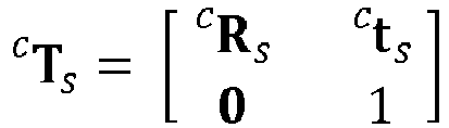
  • c T s is the camera pose homogeneous matrix which relates the display geometric frame F s to the camera geometric frame F c .
  • T s c R s c t s c 0 1
  • I c is the captured camera image and I c ( u,v ) is a pixel value at coordinates [ u , v ] .
  • I v is the undistorted output image.
  • I v size is equal to the displayed video size: [w, h].
  • I v u v I c u c v c ⁇ u c ⁇ [ 0 ; w [ v c ⁇ [ 0 ; h [ u c v c 1 ⁇ H c s u v 1
  • Each intermediate image would then be compared to the current frame and the best intermediate image would be kept (which would give the best value of the positioning weight ⁇ ). Time alignment would then be done on this basis.
  • the complexity increases linearly with the number of intermediate images, and reducing the number of intermediate images may reduce the matching robustness.
  • this simple (but inefficient) solution is replaced by a correlation calculation, which is more efficient while limiting the number of operation to be done for calculating the optimal positioning weight ⁇ directly, with no approximation (no intermediate generated images).
  • the two reference frames comprises a previous frame and a next frame (for example two consecutive frames) and the time interpolation is based on:
  • a first way of processing the captured frames (from the camera) and the reference frames is disclosed.
  • This first context of implementation takes account of the rendering of the video on the display panel, the time took by the camera for capturing one single frame and the geometrical transformation to operate to the captured frames. These operations are used for matching the captured frame with the reference frames.
  • Various improvements of this specific embodiment are disclosed herein below.
  • Image displayed by the display panel (this image is called L d ) is not a simple frame of I .
  • a display panel has some latency and this latency produces artefacts.
  • I is a discrete set of frames.
  • the observation time t is defined on a continuous scale and is bounded by the timestamps of two frames: t a ⁇ t ⁇ t b
  • L d f I t a , I t b , t , t a , t b
  • f is a smooth, continuously differentiable (on the domain) function.
  • the function f blends I [ t a ] ,I [ t b ] together, with I [ t a ] being more important if t is close to t a and I [ t b ] being more important if t is close to t b .
  • t a and t b are functions of the current time t in the integrated part. This means that more than two input frames may be used to form L c . Being able to use more than two input frames is very important as the camera integration time may be higher than the video frame duration. This is for example the case when the display panel D2 displays frames at a 100 Hz rate (100 images per second), whereas the camera captures the displayed frames at a 25 Hz or 30Hz rate (25 or 30 images per second).
  • the size ( w m , h m ) in meters of the display panel is known a priori.
  • the camera calibration is also known a priori and is defined by the 3x3 matrix K cam .
  • the video frames size ( w v , h v ) in pixels is also known a priori.
  • the function w represents the perspective projection function. This is the division of the three elements of the vector by the third component.
  • the system estimates the pose by minimizing this equation: argmin T r c , t 0 , t 1 ⁇ 0 ⁇ v r ⁇ h v 0 ⁇ u r ⁇ w v ( L c t 0 t 1 u r v r ⁇ I c K cam w T r c g u r v r
  • h v and w v may not be the real video size but a downsized version to fasten computation, as explained herein below, in specific improvement.
  • I r ⁇ I 1 + 1 ⁇ ⁇ I 2 zncc I r
  • I v I r .
  • I v I r ⁇ I r ⁇ zncc I r I v ⁇ 1 + 1 ⁇ ⁇ ⁇ 2 ⁇ ⁇ I 1 + 1 ⁇ ⁇ I 2 ⁇ .
  • is not discretized and its optimal value is found using only five (5) multiplications and five (5) additions, which is significantly low, even for a low resources processing device.
  • the maximal possible score is found without explicit variation of the combination coefficient. Finding the global maximal value is then only a matter of finding the consecutive frames pair with the highest score. Additionally, the proposed method guarantees that no approximation will hide a peak in the score function.
  • the disclosure also proposes a device for temporally aligning a current frame with reference frames.
  • the device can be specifically designed for pose estimation or any electronic device comprising non-transitory computer readable medium and at least one processor configured by computer readable instructions stored in the non-transitory computer readable medium to implement any method in the disclosure.
  • the device for temporally aligning a current frame with reference frames includes a Central Processing Unit (CPU) 42, a Random Access Memory (RAM) 41, a Read-Only Memory (ROM) 43, a storage device which are connected via a bus in such a manner that they can carry out communication among them.
  • CPU Central Processing Unit
  • RAM Random Access Memory
  • ROM Read-Only Memory
  • the CPU controls the entirety of the device by executing a program loaded in the RAM.
  • the CPU also performs various functions by executing a program(s) (or an application(s)) loaded in the RAM.
  • the RAM stores various sorts of data and/or a program(s).
  • the ROM also stores various sorts of data and/or a program(s) (Pg).
  • the storage device such as a hard disk drive, a SD card, a USB memory and so forth, also stores various sorts of data and/or a program(s).
  • the device performs the method for temporally aligning a current frame with reference frames as a result of the CPU executing instructions written in a program(s) loaded in the RAM, the program(s) being read out from the ROM or the storage device and loaded in the RAM.
  • the device can be a server, a computer, a pad, a smartphone or a camera in itself.
  • the device comprises at least one input adapted for receiving the reference frames, at least one further input adapted to receiving the current frame (e.g. the captured frames), the processor(s) for estimating the pose of the camera, and at least one output adapted to outputting the data associated with the pose estimation.
  • the generated information is advantageously synchronized with the displayed frames for augmented reality, with a view to e.g. advertisement, second screen complements or games, but can also be disconnected from the displayed video.
  • the disclosure also relates to a computer program product comprising computer executable program code recorded on a computer readable non-transitory storage medium, the computer executable program code when executed, performing the method for temporally aligning a current frame with reference frames.
  • the computer program product can be recorded on a CD, a hard disk, a flash memory or any other suitable computer readable medium. It can also be downloaded from the Internet and installed in a device so as to estimate the pose of a camera as previously exposed.
  • the method further comprises determining a pose estimation associated with said current frame of the current video stream, from spatially correlating said current frame and said at least two reference frames based on said time alignment.
  • said method is applied to augmented reality or interactivity.
  • determining the time alignment of said current frame is done with respect to a predetermined number of said at least two reference frames.
  • predetermined number is two.
  • said two reference frames including a previous frame and a next frame
  • said time interpolation being based on a correlation S1 between the previous frame and said current frame, a correlation S2 between the next frame and the current frame, and a correlation S3 between the previous frame and the next frame
  • the time alignment of said current frame being possible with respect to at least two sets of said predetermined number of said at least two reference frames
  • said method comprises determining said time alignment with respect to one of said sets of said at least two reference frames that provides a highest correlation of said current frame with the time interpolation of said reference frames, among said at least two sets of said at least two reference frames.
  • determining said time alignment comprises selecting said at least two reference frames within a time window including a current time corresponding to said current frame and having a predetermined time length.
  • said correlations are respectively applied to centered versions of said current frame and said at least two reference frames, a centered version of a frame comprising pixels being given by a difference between said frame and an averaging of said frame over said pixels.
  • said at least two reference frames are consecutive in said reference video stream.
  • said current video stream being obtained in real time, determining said time alignment is done in real time.
  • said current video stream corresponds to an adapted version of said reference video stream.
  • the method comprises receiving said current video stream and said reference video stream at at least one input, determining said time alignment with at least one processor, and outputting information generated partly from said time alignment at at least one output.
  • the disclosure also relates to a device for time aligning frames of video stream according to the previous disclosed methods.
  • the disclosure relates to a device for time aligning a current frame of a current video stream with respect to reference frames of a reference video stream, said current video stream corresponding to at least one part of said reference video stream, said device comprising at least one processor for:
  • the device is further advantageously configured for carrying out a method for time aligning frames in any of its above execution modes.
  • the disclosure is also relevant to a mobile apparatus comprising a camera, and further comprising a device for time aligning frames as mentioned above.
  • the present disclosure is also related to a computer program product downloadable from a communication network and/or recorded on a medium readable by a computer and/or executable by a processor, comprising program code instructions for implementing the method as described above.
  • the present disclosure also concerns a non-transitory computer-readable medium comprising a computer program product recorded thereon and capable of being run by a processor, including program code instructions for implementing the method as described above.
  • Such a computer program may be stored on a computer readable storage medium.
  • a computer readable storage medium as used herein is considered a non-transitory storage medium given the inherent capability to store the information therein as well as the inherent capability to provide retrieval of the information therefrom.
  • a computer readable storage medium can be, for example, but is not limited to, an electronic, magnetic, optical, electromagnetic, infrared, or semiconductor system, apparatus, or device, or any suitable combination of the foregoing.
  • references in the specification to "one embodiment” or “an embodiment”, indicate that the embodiment described may include a particular feature, structure, or characteristic, but every embodiment may not necessarily include the particular feature, structure, or characteristic. Moreover, such phrases are not necessarily referring to the same embodiment. Further, when a particular feature, structure, or characteristic is described in connection with an embodiment, it is submitted that it is within the knowledge of one skilled in the art to affect such feature, structure, or characteristic in connection with other embodiments whether or not explicitly described.

Landscapes

  • Engineering & Computer Science (AREA)
  • Computer Vision & Pattern Recognition (AREA)
  • Physics & Mathematics (AREA)
  • General Physics & Mathematics (AREA)
  • Theoretical Computer Science (AREA)
  • Multimedia (AREA)
  • Signal Processing (AREA)
  • Studio Devices (AREA)
  • Image Analysis (AREA)

Abstract

A method for a method for time aligning a current frame of a current video stream with respect to reference frames of a reference video stream, said current video stream corresponding to at least one part of said reference video stream,. According to the disclosure the method comprises:- obtaining at least two reference frames corresponding to at least part of at least some of multiple displayed frames displayed on a display;- obtaining current frame from images of said displayed frames captured with a camera by shooting said display;- determining a time alignment of said current frame with respect to said at least two reference frames by correlating said current frame with a time interpolation of said at least two reference frames, said time interpolation being based on correlations between said current frame and respectively each of said at least two reference frames, and on at least one correlation between at least two of said selected reference frames together. Corresponding device, and applications to augmented reality

Description

    1. Technical field
  • The present disclosure relates to the field of video processing. More specifically, the present disclosure relates to computer vision. More particularly, the methods and devices proposed in the present disclosure are adapted for time aligning a current frame of a current video stream with respect to reference frames of a reference video stream.
  • 2. Background
  • A major field of computer vision is the camera pose estimation. Several situations may occur for which estimating the pose of the camera is of importance. This is for example the case for augmented reality or for mixed reality. Usually, estimating the pose of a camera consists in estimating the position and/or orientation of the camera. This is important for example when the camera is moving during the video processing tasks.
  • 3. Summary
  • It is disclosed a method for time aligning a current frame of a current video stream with respect to reference frames of a reference video stream, said current video stream corresponding to at least one part of said reference video stream,
  • According to the disclosure, the method comprises:
    • obtaining at least two reference frames corresponding to at least part of at least some of multiple displayed frames displayed on a display;
    • obtaining current frame from images of said displayed frames captured with a camera by shooting said display;
    • determining a time alignment of said current frame with respect to said at least two reference frames by correlating said current frame with a time interpolation of said at least two reference frames, said time interpolation being based on correlations between said current frame and respectively each of said at least two reference frames, and on at least one correlation between at least two of said selected reference frames together.
    4. Brief description of the drawings
    • figure 1 is a schematic block diagram illustrating the method for time alignment of a current frame with reference frames;
    • figure 2 illustrates a system for carrying out the method;
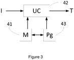
    • figure 3 illustrates a device for implementing the disclosed method.
    5. Description 5.1. General principle
  • For augmented reality, it is recommended to properly insert virtual objects in the real scene: the virtual camera used to render objects must be "aligned" with the real camera. The augmentation of the quality of the insertion is directly correlated with the quality of the camera's pose estimation.
  • The camera pose is commonly estimated with respect to some reference geometric frame(s). The estimated camera pose will be a rigid transformation between this reference frame(s) and the camera geometric frame(s).
  • Usually, the reference frame must be known a priori to enable offline edition of the augmented reality scenario. This means that either the environment is known or some fixed recognizable object (with a known pose) is visible in the camera point of view, so that the processing may be done in view of this fixed recognizable object.
  • Current production grade augmented reality systems are using planar recognizable objects known as markers. These markers are designed to be easily recognizable by a camera sensor (their content is unique and texture-rich) and are typically printed on sheets of papers.
  • Several solutions exist, based on static templates, and work for known situations, where the static template is visible and where the static template may be easily recognized among the other objects of the scene. However, the first problem of these solutions is the necessity of having these static templates: this is not convenient for a home use of these solutions because the user needs to position these templates before using the augmented reality application, which may lead to a quite deceptive experience. Additionally, in many scenarios, including living room usage (moreover in dark lighting conditions), these static templates are either not correctly perceived or not perceived at all. This implies that the augmented reality application will not work properly or not work at all.
  • Solutions have been proposed for estimating the pose of the camera by using a display, on which reference frames are displayed, these reference frames being captured by a camera and correlated with the reference frames. However, this smart solution may be limited by the usually reduced resources of the processing device (usually a smartphone or a tablet). One aspect of this pose estimation method is related to the time alignment of the captured frames with the reference frames.
  • Indeed, the frames displayed on the display may be used as reference pattern to be tracked in the image by a template based homography tracker. However, camera and display panel (i.e. television) are not synchronized: acquired frames may contain a linear combination of two or more reference images. It is thus necessary to quickly estimate which reference frames combination is displayed (and captured) by the processing device. One solution is to artificially create images, based on two or more reference frames, so as to create intermediate references frames which may be compared to the acquired current frame (i.e. the frame acquired by the camera). However, the complexity obviously increases linearly with the number of intermediate references frames. On the other side, reducing the number of intermediate images may reduce the matching robustness. Additionally, this simple method necessitates the use of many resources which may not be available in the processing device.
  • Thus, there's a need for having a frame time aligning method and device which do not have these drawbacks of prior art techniques.
  • The disclosure allows producing a fast and efficient time aligning for determining which of said reference frames corresponds to said current frame.
  • The general principle of the disclosure consists in optimizing the way reference data are obtained. Previously, reference data were obtained using static templates which were positioned in the shooting area of the camera: the static templates were shot by the camera giving reference data in the frames shot by the camera, thus leading, by a computational process, to an estimation of the camera pose (usually as a function of the planar surface of the static templates). According to the present disclosure, reference data are obtained from video frames which are displayed on a display device. The global computational process consists in estimating the camera pose in view of these reference data which are called reference frames.
  • Thus, thanks to this technique, it is possible to precisely estimate the pose of the camera without needing any static template. This leads to a better service rendered by the various applications that may need an estimation of a pose of a camera, because the user is not required to install any additional component. This also leads to better results in dark or shadowed conditions since it is supposed that the camera shoot (at least partially) a display device which emits light. Thus even in dark, the proposed solution ensures that sufficient light is present in order to allow at least a partially captures of the pictures by the shooting camera. In this context, more precisely, the object of the disclosure is to describe a method for temporally aligning a current frame (noted Lc) with respect to reference frames (F).
  • Figure 1 exposes the main steps of the proposed technique. It is disclosed a method for time aligning a current frame of a current video stream with respect to reference frames of a reference video stream, said current video stream corresponding to at least one part of said reference video stream. In the context of the disclosure, the current video stream may not being time aligned with the reference video stream. The method comprises:
    • obtaining (10) at least two reference frames (F) corresponding to at least part of at least some of multiple displayed frames displayed on a display;
    • obtaining (20) current frame (Lc) from images of said displayed frames captured with a camera by shooting said display;
    • determining (30) a time alignment (TAL) of said current frame with respect to said at least two reference frames by correlating said current frame (Lc) with a time interpolation of said at least two reference frames (F), said time interpolation being based on correlations between said current frame and respectively each of said at least two reference frames, and on at least one correlation between at least two of said selected reference frames together.
  • The disclosed method, for time correlation, is applied in a global context and global method which comprises shooting (at least partially) a device on which reference frames of a video are displayed. In the same time, reference frames are transmitted to a device. Using the reference frames which are received and the reference frames which are captured (shooted), pose estimation is done. Globally the pose estimation process consists in aligning, geometrically and temporally, the received referenced frames and the captured referenced frames. Thanks to these two alignments (or synchronizations) the pose of the camera is estimated. This global method allows obtaining a pose estimation, this pose being used to locate objects, for example in augmented reality scenes. The display which is shot by the camera is, according to a global situation, a part of fixed display panel in said environment (for example a TV or a computer screen display). The display panel may also be part of a display set, comprising the display and another device, such as a set top box. In such a situation, the reference frames may be obtained directly from the set top box. In a specific embodiment, the set top box in itself may be able to process the proposed method. In another embodiment, the camera may be included in a user device (smartphone, pad), and the proposed method may be directly processed by this user device. The user device is then in charge of receiving the reference frames and to determine the pose of the user's device camera in view of the reference frames and the captured frames. According to the disclosure, obtaining reference frames may be done in several ways: the first one consists in receiving the reference frames as and when they are transmitted (or displayed) by the display device; this is the case, for example, of a so called "streaming" transmission of the frames to be displayed to a set top box (case of a broadcast for example). A second case may consist in storing the frames (e.g. the movie, the TV show, etc.) and receiving timestamps of the reference frames: the device already has the frames and it receives the information relative to the frames which are (to be) displayed, so that it can process these frames accordingly. A mix of the two previous cases is also possible. The point is that the device which implements the method has to have sufficient information for correlating (in time and in space) current frame and reference frames. Additionally, the pose estimation may have several forms: it may comprise a rigid transformation of one image to one other; it may also comprise a discrete (time) transformation.
  • In other words, the global method comprises receiving said reference frames from a telecommunication transmission medium, receiving said current frame from said camera, determining said pose estimation with at least one processor and outputting data associated with said pose estimation for providing a user of said camera with information generated partly from said data associated with said pose estimation.
  • Figure 2 discloses a description of an embodiment of a system in which the proposed technique may be implemented. For clarity, the same references than in figure 1 have been kept. A device D1 is connected to a display panel D2 and controls a video playback on this display panel. D1 has knowledge about the video for at least a time window W1 before and after the currently displayed frame on D2 (note that D1 may be directly integrated into D2). Let's define I, the video, as an array of frames indexed by the frame timestamp.
  • A user's device D3 (such as glasses or a tab, smartphone, AR helmet - for Augmented Reality, etc.) is connected to a processing device D4 (D3 may be the same unit than D4 or integrated into D4). D1 and D4, D3 and D4 are connected through a high bandwidth/low latency connection (for example a wireless one).
  • Whenever asked, D1 sends to D4 a set of frames F (Ix-n,...Ix+n) covering the current time window W 1: F = I t t W 1
    Figure imgb0001
  • W 1 is large enough to consider the latency between the display and the tracking process: the purpose is to be sure that - at any time - one of the frames in F is the one displayed on D2.
  • D2 is (at least partially) filmed by the camera (C) of D3, which transmits images data IC (a set of frames Icy-m,...Icy+m) to the device D4.
  • D4 has information about the tracking result at the previous time step. The tracking result is a geometrical transformation between the camera C (contained by D3) and D2. It also has information about the starting and finishing times of the previous camera shutter opening (the time is for example defined by the capture video frames timestamps, or the capture video frame rate).
  • Using this previous time information and knowledge about the camera shutter (typically the frame rate of the captured images), one can roughly deduce a time window W 2 contained in W 1: card W 1 card W 2 or card W 1 > > card W 2 ,
    Figure imgb0002
    depending on implementation.
  • Knowing W 2, F and the images Ic acquired by the camera (which will form the current frame), the proposed technique estimates the relative transformation cTr, where
    Figure imgb0003
    is the display panel geometric frame.
  • Various embodiments of this technique may be implemented. In the following a specific implementation is presented. In this implementation, it is assumed that the camera pose is known for the previous time step (basically, that the transformation cTr is known for the previous iteration, i.e. that cT r(n-1) is known).
  • In this implementation, the global system is considered to be initialized. It is also assumed that the previous time step pose is relatively close to the current time step pose. Initialization is not covered by this implementation: that means that the previously disclosed technique is not used, in the same way, for determining cT r(0), the first transformation.
  • However, according to the disclosure, the initialization (i.e the obtaining of the first transformation), may be done by using additional data coming both from the camera and the reference frames. Hence, it is proposed to initialize the system with help of the audio stream which is captured along with the captured frames and with the sound which is included in or aside the reference frame. The technique consists in, before the processing applied to the frame, processing the audio stream to obtain the necessary information for coarsely estimating the time at which the capture is done. According to the proposed technique, the audio stream in watermarked, so that estimating the time at which the capture is done only necessitates to periodically find the watermark in the audio stream.
  • According to the disclosure, in specific embodiments, the frames (reference frames and consequently captured frames) are watermarked. The initialization of the system can also be done by using the watermarked frames, just like audio streams. Advantageously, the watermark technique has two main features: the first one is to be sufficiently resistant for being captured by the camera; the second one is that it evolves in time: that means that, for example, knowing the watermark allows knowing to which frame (or group of frames) it is referenced to. This second feature allows speeding up the pose estimation process, since recognizing the watermark, both in the reference frames and in the captured frames implies that it is easier to timely map these frames, thus, once the frames are timely mapped, the pose estimation may be found by using a geometric transformation.
  • Considering the previously presented system, let us explain the main steps of the proposed technique in a first embodiment, by using the previous references (of figures 1 and 2, which are applicable to this embodiment).
  • In a first step (10), reference frames (F) are obtained; reference frames belong to a set of reference frame and extend on a given period of time (W 1);
  • In a second step (20), captured frames (Id) are obtained; captured frames belong to a set of captured frames and extend on a given period of time (W 2), where W 2 is smaller than W 1. According to a specific embodiment, one camera frame is acquired to compute one transformation. W2 is a subset of W1 refined using camera information. It limits the set of reference frames which are of interest.
  • In a third step (30), a time alignment of the current frame (Lc) with respect to the two reference frames (F) is made. This time alignment is done by correlating said current frame (Lc) with a time interpolation of at least two reference frames (F1, F2). The time interpolation is based on correlations between said current frame (Lc) and respectively each of said at least two reference frames (F1, F2), and on at least one correlation between at least two of said selected reference frames (F1, F2) together.
  • Thus the proposed method allows achieving the time correlation in a context of the overall global method proposed herein before.
  • Additionally, a space correlation is made between reference frames (F) and capture frames (Lc) so as to determine a transformation cT r(n); this transformation being calculated, in a specific embodiment, as a function of a previously obtained transformation ( cT r(n-1)). This space correlation is mixed with the time correlation.
  • Thus, thanks to the proposed technique, the method allows temporally alinging the captured frames obtained by the camera so as to match the reference frames which are obtained by another channel. Matching the two allows finding a transformation which may then be used to render additional digital content in a mixed reality scene: for example, this transformation may be use to change the appearance of a digital object in the scene; the digital object is then correctly oriented in view of the transformation applied on this object. The temporal alignment will be better understood with the following details. c K is the camera intrinsic matrix which relates some 2D coordinates (in meters) in the camera image plane to their associated pixel coordinates. s K is the TV intrinsic matrix which relates some 2D coordinates (in meters) in the display (TV panel) plane to their associated video pixel coordinates. As previously introduced, c T s is the camera pose homogeneous matrix which relates the display geometric frame Fs to the camera geometric frame Fc. T s c = R s c t s c 0 1
    Figure imgb0004
  • A homography matrix is computed as H s c = K c R s c + t s c 0 0 1 K s 1
    Figure imgb0005
  • This homography matrix is used to undistort the display content. Ic is the captured camera image and Ic (u,v) is a pixel value at coordinates [u,v]. Iv is the undistorted output image. Iv size is equal to the displayed video size: [w, h]. I v u v = I c u c v c u c [ 0 ; w [ v c [ 0 ; h [
    Figure imgb0006
    u c v c 1 H c s u v 1
    Figure imgb0007
  • For temporally aligning the simplest solution is to compare Iv with an ordered set F of possible video frames. However, one must also compare with linear combinations of successive video frames to be able to recognize captured frames (Lc) with this artefact. A straightforward approach would be to create intermediate images (by varying a positioning weight α of reference frames) and to compare all n intermediate generated images: αS i + 1 α S i + 1 α 1.. n n
    Figure imgb0008
  • Each intermediate image would then be compared to the current frame and the best intermediate image would be kept (which would give the best value of the positioning weight α). Time alignment would then be done on this basis. However, as previously exposed, the complexity increases linearly with the number of intermediate images, and reducing the number of intermediate images may reduce the matching robustness.
  • Thanks to the proposed method of the disclosure, this simple (but inefficient) solution is replaced by a correlation calculation, which is more efficient while limiting the number of operation to be done for calculating the optimal positioning weight α directly, with no approximation (no intermediate generated images).
  • More specifically, according to the disclosure, the two reference frames comprises a previous frame and a next frame (for example two consecutive frames) and the time interpolation is based on:
    • a correlation S1 between the previous frame and the current frame;
    • a correlation S2 between the next frame and the current frame; and
    • a correlation S3 between the previous frame and the next frame.
  • The time interpolation then corresponds to a linear normalized time positioning weight α between the previous frame and the next frame, said time positioning weight α being given by: α = S 2 S 3 + S 1 S 1 S 3 + S 2 S 3 S 1 S 2
    Figure imgb0009
  • A description of a general context of implementation of the proposed method is disclosed herein after. It has to be understood however, that this specific embodiment does not limit the scope of the disclosure and that the determination of the transformation may be obtained differently in view of specific implementation conditions and parameters.
  • 5.2. Description of a general context of implementation of the proposed method
  • In a first general context of implementation, a first way of processing the captured frames (from the camera) and the reference frames is disclosed. This first context of implementation takes account of the rendering of the video on the display panel, the time took by the camera for capturing one single frame and the geometrical transformation to operate to the captured frames. These operations are used for matching the captured frame with the reference frames. Various improvements of this specific embodiment are disclosed herein below.
  • 5.2.1. Display video rendering
  • Image displayed by the display panel (this image is called Ld ) is not a simple frame of I. A display panel has some latency and this latency produces artefacts. I is a discrete set of frames. The observation time t is defined on a continuous scale and is bounded by the timestamps of two frames: t a < t < t b
    Figure imgb0010
  • The image Ld is the result of : L d = f I t a , I t b , t , t a , t b
    Figure imgb0011
  • Where f is a smooth, continuously differentiable (on the domain) function. The function f blends I[ta ],I[tb ] together, with I[ta ] being more important if t is close to ta and I[tb ] being more important if t is close to tb.
  • Thus a first bias of the frames captured by the camera is integrated.
  • 5.2.2. Camera shutter
  • It has been explained that the camera was shooting, at least partially, the display panel D2. However, the camera image capture is not instantaneous. The shutter stays open for a fixed amount of time ts = t 1 - t 0 .
  • Ignoring the geometric distortion of the display screen in the camera view, the captured image Lc (i.e. the current frame which has to be compared with the reference frames) is: L c t 0 t 1 = t = t 0 t 1 f I t a t , I t b t , t , t a t , t b t
    Figure imgb0012
  • Note that ta and tb are functions of the current time t in the integrated part. This means that more than two input frames may be used to form Lc. Being able to use more than two input frames is very important as the camera integration time may be higher than the video frame duration. This is for example the case when the display panel D2 displays frames at a 100 Hz rate (100 images per second), whereas the camera captures the displayed frames at a 25 Hz or 30Hz rate (25 or 30 images per second).
  • Thus a second bias of the frames capture by the camera is integrated.
  • 5.2.3. Geometry
  • Assume (for simplification) that the reference frame is attached to the top left corner of the display panel D2. The size (wm, hm ) in meters of the display panel is known a priori. The camera calibration is also known a priori and is defined by the 3x3 matrix Kcam . The video frames size (wv, hv ) in pixels is also known a priori.
  • A 3D point rm, which lies on the display frame, lies on the Z = 0 plane: m r = X r Y r 0
    Figure imgb0013
    rm is any point on the screen. rm is on the plane (in the geometrical sense) of the display frame, i.e. Z = 0 since the mark coincides with the top left corner of the display.
  • This point may be transformed in the camera frame: m c = T r c m r
    Figure imgb0014
  • The image coordinates are then given by (These are the coordinates of the 3D point rm when it is transformed in the frame of the camera, projected and modified to take into account the calibration of the camera. This is a point in pixels): u c v c 1 = k cam X c Z c Y c Z c 1 = K cam w X c Y c Z c = K cam w c m
    Figure imgb0015
  • The function w represents the perspective projection function. This is the division of the three elements of the vector by the third component.
  • For each pixel rp in Lc, the associated rm (in meters) is then: p r = u r v r 1
    Figure imgb0016
    K input = w v w m 0 0 0 h v h m 0 0 0 1
    Figure imgb0017
    m r = K input 1 p r = g p r
    Figure imgb0018
  • This is a second definition. It is explained here how to move from point to pixel in the video at a point in meters in the reference of the screen (ortho reference). "g" is the function that performs this transformation; it is used in the previous equation.
  • So there are two geometric definitions. A first one that models how the measurement in the image of the camera of a 3D point belonging to the screen is obtained. And a second definition which makes it possible to obtain a point in meters that belongs to the screen according to its coordinates in a reference image (an image of the video).
  • These two definitions allow to better understand the minimization function below.
  • 5.2.4. Solving the problem
  • Considering the previous integration of the three biases and neglecting the motion of the camera during the integration time, the system estimates the pose by minimizing this equation: argmin T r c , t 0 , t 1 0 v r h v 0 u r w v ( L c t 0 t 1 u r v r I c K cam w T r c g u r v r
    Figure imgb0019
  • Note that hv and wv may not be the real video size but a downsized version to fasten computation, as explained herein below, in specific improvement.
  • Thus, using this integration technique, one can use a video as a model for pose estimation. In augmented reality for entertainment, this is a strong advantage as one gets rid of external markers and the marker is directly integrated into the context.
  • 5.3. Proof of an embodiment of the proposed temporally alignment method (for two reference frames)
  • In this section, a proof of an embodiment of the proposed method is made. Let consider images as vectors (losing 2D structures and stacking rows together). A solution to compare two vectors v 1 and v 2 is cross-correlation: cos v 1 v 2 ^ v 1 v 2 = v 1 . v 2
    Figure imgb0020
    cos v 1 v 2 ^ = v 1 . v 2 v 1 v 2
    Figure imgb0021
  • For images, the basis must be centered for correct assessment of cross-correlation. zncc v 1 v 2 = v 1 v 1 . v 2 v 2 v 1 v 1 v 2 v 2
    Figure imgb0022
  • Where x = 1 size x i = 0 size x x i size x
    Figure imgb0023
  • Let consider only two consecutive video reference frames I 1 and I 2 that will be compared to the undistorted current image Iv . (it is assumed that images have been previously centered and normalized for clarity.) I v = I 1 = I 2 = 0
    Figure imgb0024
    I v = I 1 = I 2 = 1
    Figure imgb0025
    I r = αI 1 + 1 α I 2
    Figure imgb0026
    zncc I r I v = I r . I v I r I r
    Figure imgb0027
    zncc I r I v = αΙ 1 + 1 α Ι 2 αI 1 + 1 α I 2 . I v αΙ 1 + 1 α Ι 2 αΙ 1 + 1 α Ι 2
    Figure imgb0028
  • As the mean function is distributive over sums: αΙ 1 + 1 α Ι 2 = α Ι 1 + 1 α Ι 2 = 0
    Figure imgb0029
    zncc I r I v = αI 1 + 1 α I 2 . I v αI 1 + 1 α I 2
    Figure imgb0030
  • Expanding, αI 1 + 1 α I 2 . I v = αI 1 I v + I 2 I v αI 2 I v
    Figure imgb0031
    αI 1 + 1 α I 2 = αΙ 1 + 1 α Ι 2 . αΙ 1 + 1 α Ι 2
    Figure imgb0032
    αΙ 1 + 1 α Ι 2 = αΙ 1 + I 2 αΙ 2 αΙ 1 + I 2 αΙ 2
    Figure imgb0033
    αΙ 1 + 1 α I 2 = α 2 I 1 I 1 + 2 αΙ 1 I 2 2 α 2 I 1 I 2 + I 2 I 2 2 αΙ 2 I 2 + α 2 I 2 I 2
    Figure imgb0034
    αI 1 + 1 α I 2 = α 2 + 2 αI 1 I 2 2 αI 1 I 2 + 1 2 α + α 2
    Figure imgb0035
    zncc I r I v = αI 1 I v + I 2 I v αI 2 I v α 2 + 2 αI 1 I 2 2 α 2 I 1 I 2 + 1 2 α + α 2
    Figure imgb0036
  • Whatever the value of α, the following values may be precomputed: S 1 = I 1 I v
    Figure imgb0037
    S 2 = I 2 I v
    Figure imgb0038
    S 3 = I 1 I 2
    Figure imgb0039
    αS 1 + S 2 αS 2 2 α 2 + 2 αS 3 2 α 2 S 3 + 1 2 α
    Figure imgb0040
    α is defined in [0;1]. In this interval, 2 α 2 + 2 αS 3 2 α 2 S 3 + 1 2 α
    Figure imgb0041
    has only one extremum (which is a minimum), and αS 1 + S 2 - αS 2 is linear.
  • As such, the maximal value for zncc(Ir,Iv ) will be found when α is such that a zncc I r I v = 0
    Figure imgb0042
  • Which may be computed in a closed fashion: α = S 2 S 3 + S 1 S 1 S 3 + S 2 S 3 S 1 S 2
    Figure imgb0043
  • It can be noted that computing S1, S2 and S3 would be necessary in any case.
  • α is not discretized and its optimal value is found using only five (5) multiplications and five (5) additions, which is significantly low, even for a low resources processing device.
  • For each pair of consecutive frames, the maximal possible score is found without explicit variation of the combination coefficient. Finding the global maximal value is then only a matter of finding the consecutive frames pair with the highest score. Additionally, the proposed method guarantees that no approximation will hide a peak in the score function.
  • 5.4. Device for temporally aligning a current frame with reference frames
  • The disclosure also proposes a device for temporally aligning a current frame with reference frames. The device can be specifically designed for pose estimation or any electronic device comprising non-transitory computer readable medium and at least one processor configured by computer readable instructions stored in the non-transitory computer readable medium to implement any method in the disclosure.
  • According to an embodiment shown in figure 3, the device for temporally aligning a current frame with reference frames includes a Central Processing Unit (CPU) 42, a Random Access Memory (RAM) 41, a Read-Only Memory (ROM) 43, a storage device which are connected via a bus in such a manner that they can carry out communication among them.
  • The CPU controls the entirety of the device by executing a program loaded in the RAM. The CPU also performs various functions by executing a program(s) (or an application(s)) loaded in the RAM.
  • The RAM stores various sorts of data and/or a program(s).
  • The ROM also stores various sorts of data and/or a program(s) (Pg).
  • The storage device, such as a hard disk drive, a SD card, a USB memory and so forth, also stores various sorts of data and/or a program(s).
  • The device performs the method for temporally aligning a current frame with reference frames as a result of the CPU executing instructions written in a program(s) loaded in the RAM, the program(s) being read out from the ROM or the storage device and loaded in the RAM.
  • More specifically, the device can be a server, a computer, a pad, a smartphone or a camera in itself. The device comprises at least one input adapted for receiving the reference frames, at least one further input adapted to receiving the current frame (e.g. the captured frames), the processor(s) for estimating the pose of the camera, and at least one output adapted to outputting the data associated with the pose estimation. The generated information is advantageously synchronized with the displayed frames for augmented reality, with a view to e.g. advertisement, second screen complements or games, but can also be disconnected from the displayed video.
  • The disclosure also relates to a computer program product comprising computer executable program code recorded on a computer readable non-transitory storage medium, the computer executable program code when executed, performing the method for temporally aligning a current frame with reference frames. The computer program product can be recorded on a CD, a hard disk, a flash memory or any other suitable computer readable medium. It can also be downloaded from the Internet and installed in a device so as to estimate the pose of a camera as previously exposed.
  • According to an embodiment, the method further comprises determining a pose estimation associated with said current frame of the current video stream, from spatially correlating said current frame and said at least two reference frames based on said time alignment.
  • Thus, thanks to the time aligning, the pose estimation of the camera which has acquired the current frame is made easier.
  • According to an embodiment, said method is applied to augmented reality or interactivity.
  • According to a specific feature, determining the time alignment of said current frame is done with respect to a predetermined number of said at least two reference frames.
  • According to a specific embodiment, predetermined number is two.
  • According to an embodiment, said two reference frames including a previous frame and a next frame, said time interpolation being based on a correlation S1 between the previous frame and said current frame, a correlation S2 between the next frame and the current frame, and a correlation S3 between the previous frame and the next frame, said time interpolation corresponds to a linear normalized time positioning weight α between the previous frame and the next frame, said time positioning weight α being given by: α = S 2 S 3 + S 1 S 1 S 3 + S 2 S 3 S 1 S 2
    Figure imgb0044
  • According to a specific feature, the time alignment of said current frame being possible with respect to at least two sets of said predetermined number of said at least two reference frames, said method comprises determining said time alignment with respect to one of said sets of said at least two reference frames that provides a highest correlation of said current frame with the time interpolation of said reference frames, among said at least two sets of said at least two reference frames.
  • According to another feature, determining said time alignment comprises selecting said at least two reference frames within a time window including a current time corresponding to said current frame and having a predetermined time length.
  • According to an additional feature, said correlations are respectively applied to centered versions of said current frame and said at least two reference frames, a centered version of a frame comprising pixels being given by a difference between said frame and an averaging of said frame over said pixels.
  • According to an embodiment said at least two reference frames are consecutive in said reference video stream.
  • According to an embodiment, said current video stream being obtained in real time, determining said time alignment is done in real time.
  • According to a feature, said current video stream corresponds to an adapted version of said reference video stream.
  • According to a feature, the method comprises receiving said current video stream and said reference video stream at at least one input, determining said time alignment with at least one processor, and outputting information generated partly from said time alignment at at least one output.
  • According to another aspect, the disclosure also relates to a device for time aligning frames of video stream according to the previous disclosed methods.
  • More specifically, according to an embodiment, the disclosure relates to a device for time aligning a current frame of a current video stream with respect to reference frames of a reference video stream, said current video stream corresponding to at least one part of said reference video stream, said device comprising at least one processor for:
    • obtaining at least two reference frames corresponding to at least part of at least some of multiple displayed frames displayed on a display;
    • obtaining current frame from images of said displayed frames captured with a camera by shooting said display;
    • determining a time alignment of said current frame with respect to said at least two reference frames by correlating said current frame with a time interpolation of said at least two reference frames, said time interpolation being based on correlations between said current frame and respectively each of said at least two reference frames, and on at least one correlation between at least two of said selected reference frames together.
  • The device is further advantageously configured for carrying out a method for time aligning frames in any of its above execution modes.
  • The disclosure is also relevant to a mobile apparatus comprising a camera, and further comprising a device for time aligning frames as mentioned above.
  • The present disclosure is also related to a computer program product downloadable from a communication network and/or recorded on a medium readable by a computer and/or executable by a processor, comprising program code instructions for implementing the method as described above.
  • The present disclosure also concerns a non-transitory computer-readable medium comprising a computer program product recorded thereon and capable of being run by a processor, including program code instructions for implementing the method as described above.
  • Such a computer program may be stored on a computer readable storage medium. A computer readable storage medium as used herein is considered a non-transitory storage medium given the inherent capability to store the information therein as well as the inherent capability to provide retrieval of the information therefrom. A computer readable storage medium can be, for example, but is not limited to, an electronic, magnetic, optical, electromagnetic, infrared, or semiconductor system, apparatus, or device, or any suitable combination of the foregoing. It is to be appreciated that the following, while providing more specific examples of computer readable storage mediums to which the present principles can be applied, is merely an illustrative and not exhaustive listing as is readily appreciated by one of ordinary skill in the art: a portable computer diskette; a hard disk; a read - only memory (ROM); an erasable programmable read- - only memory (EPROM or Flash memory); a portable compact disc read- - only memory (CD-ROM); an optical storage device; a magnetic storage device; or any suitable combination of the foregoing.
  • It is to be understood that both the foregoing general description and the following detailed description are exemplary and explanatory and are not restrictive of the disclosure, as claimed.
  • It must also be understood that references in the specification to "one embodiment" or "an embodiment", indicate that the embodiment described may include a particular feature, structure, or characteristic, but every embodiment may not necessarily include the particular feature, structure, or characteristic. Moreover, such phrases are not necessarily referring to the same embodiment. Further, when a particular feature, structure, or characteristic is described in connection with an embodiment, it is submitted that it is within the knowledge of one skilled in the art to affect such feature, structure, or characteristic in connection with other embodiments whether or not explicitly described.

Claims (15)

  1. A method for time aligning a current frame of a current video stream with respect to reference frames of a reference video stream, said current video stream corresponding to at least one part of said reference video stream,
    characterized in that said method comprises:
    - obtaining at least two reference frames corresponding to at least part of at least some of multiple displayed frames displayed on a display;
    - obtaining current frame from images of said displayed frames captured with a camera by shooting said display;
    - determining a time alignment of said current frame with respect to said at least two reference frames by correlating said current frame with a time interpolation of said at least two reference frames, said time interpolation being based on correlations between said current frame and respectively each of said at least two reference frames, and on at least one correlation between at least two of said selected reference frames together.
  2. A device for time aligning a current frame of a current video stream with respect to reference frames of a reference video stream, said current video stream corresponding to at least one part of said reference video stream, said device comprising at least one processor configured for:
    - obtaining at least two reference frames corresponding to at least part of at least some of multiple displayed frames displayed on a display;
    - obtaining current frame from images of said displayed frames captured with a camera by shooting said display;
    - determining a time alignment of said current frame with respect to said at least two reference frames by correlating said current frame with a time interpolation of said at least two reference frames, said time interpolation being based on correlations between said current frame and respectively each of said at least two reference frames, and on at least one correlation between at least two of said selected reference frames together.
  3. The method according to claim 1 or the device according to claim 2, characterized in that it further comprises determining a pose estimation associated with said current frame of the current video stream, from spatially correlating said current frame and said at least two reference frames based on said time alignment.
  4. The method according to claim 3 or the device according to claim 3, characterized in that it is applied to augmented reality or interactivity.
  5. The method according to any of claim 1 or 3 to 4 or the device according to any of claims 2 to 4, characterized in that determining the time alignment of said current frame is done with respect to a predetermined number of said at least two reference frames.
  6. The method according to claim 5 or the device according to claim 5, characterized in that said predetermined number is two.
  7. The method according to claim 6 or the device according to claim 6, characterized in that said two reference frames including a previous frame and a next frame, said time interpolation being based on a correlation S1 between the previous frame and said current frame, a correlation S2 between the next frame and the current frame, and a correlation S3 between the previous frame and the next frame, said time interpolation corresponds to a linear normalized time positioning weight α between the previous frame and the next frame, said time positioning weight α being given by: α = S 2 S 3 + S 1 S 1 S 3 + S 2 S 3 S 1 S 2
    Figure imgb0045
  8. The method according to claim 7 or the device according to claim 7, characterized in that the time alignment of said current frame being possible with respect to at least two sets of said predetermined number of said at least two reference frames, said method comprises determining said time alignment with respect to one of said sets of said at least two reference frames that provides a highest correlation of said current frame with the time interpolation of said reference frames, among said at least two sets of said at least two reference frames.
  9. The method according to claim 1 or the device according to claim 2, characterized in that determining said time alignment comprises selecting said at least two reference frames within a time window including a current time corresponding to said current frame and having a predetermined time length.
  10. The method according to claim 1 or the device according to claim 2, characterized in that said correlations are respectively applied to centered versions of said current frame and said at least two reference frames, a centered version of a frame comprising pixels being given by a difference between said frame and an averaging of said frame over said pixels.
  11. The method according to claim 1 or the device according to claim 2, characterized in that said at least two reference frames are consecutive in said reference video stream.
  12. The method according to claim 1 or the device according to claim 2, characterized in that said current video stream being obtained in real time, determining said time alignment is effected in real time.
  13. The method according to claim 1 or the device according to claim 2 characterized in that said current video stream corresponds to an adapted version of said reference video stream.
  14. A Mobile apparatus, characterized in that it comprises a device according to any of claims 2 to 13.
  15. A Computer program product comprising computer executable program code recorded on a computer readable non-transitory storage medium, the computer executable program code when executed, performing any method according to any of claims 1 or 3 to 14.
EP18305114.3A 2018-02-05 2018-02-05 Method, device and system for estimating a pose of a camera Withdrawn EP3522113A1 (en)

Priority Applications (3)

Application Number Priority Date Filing Date Title
EP18305114.3A EP3522113A1 (en) 2018-02-05 2018-02-05 Method, device and system for estimating a pose of a camera
US16/266,079 US20190244384A1 (en) 2018-02-05 2019-02-03 Method, device and system for estimating a pose of a camera
EP19155217.3A EP3522114B1 (en) 2018-02-05 2019-02-04 Method, device and system for time aligning a frame of a video stream with respect to reference frames of a reference video stream

Applications Claiming Priority (1)

Application Number Priority Date Filing Date Title
EP18305114.3A EP3522113A1 (en) 2018-02-05 2018-02-05 Method, device and system for estimating a pose of a camera

Publications (1)

Publication Number Publication Date
EP3522113A1 true EP3522113A1 (en) 2019-08-07

Family

ID=61827657

Family Applications (2)

Application Number Title Priority Date Filing Date
EP18305114.3A Withdrawn EP3522113A1 (en) 2018-02-05 2018-02-05 Method, device and system for estimating a pose of a camera
EP19155217.3A Not-in-force EP3522114B1 (en) 2018-02-05 2019-02-04 Method, device and system for time aligning a frame of a video stream with respect to reference frames of a reference video stream

Family Applications After (1)

Application Number Title Priority Date Filing Date
EP19155217.3A Not-in-force EP3522114B1 (en) 2018-02-05 2019-02-04 Method, device and system for time aligning a frame of a video stream with respect to reference frames of a reference video stream

Country Status (2)

Country Link
US (1) US20190244384A1 (en)
EP (2) EP3522113A1 (en)

Families Citing this family (1)

* Cited by examiner, † Cited by third party
Publication number Priority date Publication date Assignee Title
CN112015231B (en) * 2020-07-31 2021-06-22 中标慧安信息技术股份有限公司 Method and system for processing surveillance video partition

Citations (1)

* Cited by examiner, † Cited by third party
Publication number Priority date Publication date Assignee Title
US6297852B1 (en) * 1998-12-30 2001-10-02 Ati International Srl Video display method and apparatus with synchronized video playback and weighted frame creation

Family Cites Families (1)

* Cited by examiner, † Cited by third party
Publication number Priority date Publication date Assignee Title
US8867896B2 (en) * 2012-02-03 2014-10-21 Vispx, Inc. Video frame marking

Patent Citations (1)

* Cited by examiner, † Cited by third party
Publication number Priority date Publication date Assignee Title
US6297852B1 (en) * 1998-12-30 2001-10-02 Ati International Srl Video display method and apparatus with synchronized video playback and weighted frame creation

Non-Patent Citations (2)

* Cited by examiner, † Cited by third party
Title
GOSHIRO YAMAMOTO ET AL: "Imperceptible On-Screen Markers for Mobile Interaction on Public Large Displays", IEICE TRANSACTIONS ON INFORMATION AND SYSTEMS., vol. E100.D, no. 9, 1 January 2017 (2017-01-01), JP, pages 2027 - 2036, XP055492153, ISSN: 0916-8532, DOI: 10.1587/transinf.2016PCP0015 *
KAWAKITA HIROYUKI ET AL: "Augmented TV: An augmented reality system for TV programs beyond the TV screen", 2014 INTERNATIONAL CONFERENCE ON MULTIMEDIA COMPUTING AND SYSTEMS (ICMCS), IEEE, 14 April 2014 (2014-04-14), pages 955 - 960, XP032651652, DOI: 10.1109/ ICMCS.2014.6911158 *

Also Published As

Publication number Publication date
EP3522114B1 (en) 2020-10-07
EP3522114A1 (en) 2019-08-07
US20190244384A1 (en) 2019-08-08

Similar Documents

Publication Publication Date Title
US8941667B2 (en) Method and apparatus for frame interpolation
US7929804B2 (en) System and method for tracking objects with a synthetic aperture
US9591237B2 (en) Automated generation of panning shots
US10565691B2 (en) Method of multi-view deblurring for 3D shape reconstruction, recording medium and device for performing the method
US8441521B2 (en) Method and apparatus for determining view of stereoscopic image for stereo synchronization
CN107111866B (en) Method and apparatus for generating extrapolated images based on object detection
US10438412B2 (en) Techniques to facilitate accurate real and virtual object positioning in displayed scenes
US20120307023A1 (en) Disparity distribution estimation for 3d tv
US12368833B1 (en) Multi-camera 3D content creation
Whitehead et al. Temporal synchronization of video sequences in theory and in practice
US20120262594A1 (en) Image-capturing apparatus
US8928765B2 (en) Noise reduction based on motion sensors
US20110096169A1 (en) Camera tracking system and method, and live video compositing system
EP3330926A1 (en) Method, device and system for estimating a pose of a camera
US10438405B2 (en) Detection of planar surfaces for use in scene modeling of a captured scene
WO2018078986A1 (en) Information processing device, information processing method, and program
US10536677B2 (en) Image processing apparatus and method
EP3493148A1 (en) View synthesis for unstabilized multi-view video
KR100945307B1 (en) Method and apparatus for compositing images from stereoscopic video
US20060192857A1 (en) Image processing device, image processing method, and program
EP3522114B1 (en) Method, device and system for time aligning a frame of a video stream with respect to reference frames of a reference video stream
CN111556338B (en) Method for detecting region in video, method for information fusion, device and storage medium
TW201320727A (en) Image processing device, image processing method, and recording medium
EP3496039A1 (en) Method, device and system for estimating a pose of a camera
CN113763472B (en) Viewpoint width determining method and device and storage medium

Legal Events

Date Code Title Description
PUAI Public reference made under article 153(3) epc to a published international application that has entered the european phase

Free format text: ORIGINAL CODE: 0009012

AK Designated contracting states

Kind code of ref document: A1

Designated state(s): AL AT BE BG CH CY CZ DE DK EE ES FI FR GB GR HR HU IE IS IT LI LT LU LV MC MK MT NL NO PL PT RO RS SE SI SK SM TR

AX Request for extension of the european patent

Extension state: BA ME

STAA Information on the status of an ep patent application or granted ep patent

Free format text: STATUS: THE APPLICATION IS DEEMED TO BE WITHDRAWN

18D Application deemed to be withdrawn

Effective date: 20200208