EP3521883A1 - Optical fiber colored core, optical fiber cable, and method for manufacturing optical fiber colored core - Google Patents
Optical fiber colored core, optical fiber cable, and method for manufacturing optical fiber colored core Download PDFInfo
- Publication number
- EP3521883A1 EP3521883A1 EP17856313.6A EP17856313A EP3521883A1 EP 3521883 A1 EP3521883 A1 EP 3521883A1 EP 17856313 A EP17856313 A EP 17856313A EP 3521883 A1 EP3521883 A1 EP 3521883A1
- Authority
- EP
- European Patent Office
- Prior art keywords
- optical fiber
- layer
- modulus
- young
- primary
- Prior art date
- Legal status (The legal status is an assumption and is not a legal conclusion. Google has not performed a legal analysis and makes no representation as to the accuracy of the status listed.)
- Withdrawn
Links
Images

Classifications
-
- G—PHYSICS
- G02—OPTICS
- G02B—OPTICAL ELEMENTS, SYSTEMS OR APPARATUS
- G02B6/00—Light guides; Structural details of arrangements comprising light guides and other optical elements, e.g. couplings
- G02B6/44—Mechanical structures for providing tensile strength and external protection for fibres, e.g. optical transmission cables
- G02B6/4479—Manufacturing methods of optical cables
- G02B6/4482—Code or colour marking
-
- G—PHYSICS
- G02—OPTICS
- G02B—OPTICAL ELEMENTS, SYSTEMS OR APPARATUS
- G02B6/00—Light guides; Structural details of arrangements comprising light guides and other optical elements, e.g. couplings
- G02B6/02—Optical fibres with cladding with or without a coating
- G02B6/02395—Glass optical fibre with a protective coating, e.g. two layer polymer coating deposited directly on a silica cladding surface during fibre manufacture
-
- G—PHYSICS
- G02—OPTICS
- G02B—OPTICAL ELEMENTS, SYSTEMS OR APPARATUS
- G02B6/00—Light guides; Structural details of arrangements comprising light guides and other optical elements, e.g. couplings
- G02B6/44—Mechanical structures for providing tensile strength and external protection for fibres, e.g. optical transmission cables
- G02B6/4401—Optical cables
- G02B6/4429—Means specially adapted for strengthening or protecting the cables
-
- G—PHYSICS
- G02—OPTICS
- G02B—OPTICAL ELEMENTS, SYSTEMS OR APPARATUS
- G02B6/00—Light guides; Structural details of arrangements comprising light guides and other optical elements, e.g. couplings
- G02B6/44—Mechanical structures for providing tensile strength and external protection for fibres, e.g. optical transmission cables
- G02B6/4479—Manufacturing methods of optical cables
- G02B6/4486—Protective covering
-
- G—PHYSICS
- G02—OPTICS
- G02B—OPTICAL ELEMENTS, SYSTEMS OR APPARATUS
- G02B6/00—Light guides; Structural details of arrangements comprising light guides and other optical elements, e.g. couplings
- G02B6/46—Processes or apparatus adapted for installing or repairing optical fibres or optical cables
- G02B6/56—Processes for repairing optical cables
- G02B6/562—Processes for repairing optical cables locatable, e.g. using magnetic means
Definitions
- the present invention relates to an optical fiber colored core wire, an optical fiber cable, and a method of manufacturing an optical fiber colored core wire.
- an optical fiber colored core wire as disclosed in Patent Document 1 is known.
- the optical fiber colored core wire includes a bare optical fiber, a primary layer covering the bare optical fiber, a secondary layer covering the primary layer, and a colored layer disposed outside the secondary layer.
- the primary layer of a soft material having a small Young's modulus
- an external force applied to the bare optical fiber can be relieved, and an increase in transmission loss of light due to the external force can be suppressed.
- the secondary layer disposed outside the primary layer of a hard material having a large Young's modulus the bare optical fiber and the primary layer can be protected from an external force.
- the colored layer is colored in order to discriminate the optical fiber colored core wires from each other.
- Patent Document 1 Japanese Unexamined Patent Application, First Publication No. 2013-134477
- the above-described primary layer may be formed of a UV curable resin.
- the UV curable resin to be the primary layer is cured by irradiation with UV light, reliability of the optical fiber colored core wire may be deteriorated due to insufficient curing.
- the present invention has been achieved in view of the above circumstances, and an object thereof is to secure reliability of an optical fiber colored core wire in which a primary layer is formed of a UV curable resin.
- an optical fiber colored core wire includes: the bare optical fiber; a primary layer formed of a UV curable resin covering the bare optical fiber; a secondary layer formed of a UV curable resin covering the primary layer; and a colored layer disposed outside the secondary layer and formed of a colored UV curable resin, in which the primary layer has a Young's modulus of 70% or more with respect to a saturated Young's modulus of the primary layer.
- Fig. 1 is a cross-sectional view of an optical fiber colored core wire according to the present embodiment.
- an optical fiber colored core wire 1 includes the bare optical fiber 2, a primary layer 3, a secondary layer 4, and a colored layer 5.
- the bare optical fiber 2 is formed of, for example, quartz-based glass and transmits light.
- the bare optical fiber 2 has, for example, a mode field diameter (MFD) of 8.2 to 9.6 ⁇ m in light having a wavelength of 1310 nm.
- the primary layer 3 is formed of a UV curable resin and covers the bare optical fiber 2.
- the secondary layer 4 is formed of a UV curable resin and covers the primary layer 3.
- the colored layer 5 is formed of a colored UV curable resin and is disposed outside the primary layer 3 and the secondary layer 4.
- UV curable resins to be the primary layer 3, the secondary layer 4, and the colored layer 5 may be the same as or different from each other.
- UV curable resins include an acrylate resin.
- the optical fiber colored core wire 1 can be used, for example, as an intermittently fixed optical fiber tape.
- the intermittently fixed optical fiber tape is an optical fiber tape in which a plurality of the optical fiber colored core wires 1 is juxtaposed and the adjacent optical fiber colored core wires 1 are intermittently connected to each other with a plurality of connectors.
- the intermittently fixed optical fiber tape can be rolled in a width direction to form a tubular shape or folded. Therefore, by using the intermittently fixed optical fiber tape, the plurality of optical fiber colored wires 1 can be bundled at high density.
- the optical fiber colored core wire 1 can be used for a loose tube cable, a slot type cable, a ribbon type center tube cable, a wrapping tube cable, a micro duct cable, and the like.
- the micro duct cable is a type of loose tube cable and is obtained by packing optical fibers at high density in a loose tube having a small diameter. Due to such a structure, relatively strong side pressure acts on the optical fiber colored core wire 1 in the loose tube cable, and transmission loss of light may increase due to microbending.
- the secondary layer 4 or the colored layer 5 preferably has a Young's modulus of 700 MPa or more and 1400 MPa or less, for example.
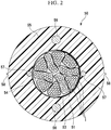
- Fig. 2 is a diagram showing an example of an optical fiber cable 50 using the optical fiber colored core wire 1.
- the optical fiber cable 50 includes the plurality of optical fiber colored core wires 1, a binding material 53, a wrapping tube 54, a cylindrical sheath 55, a pair of tension-resisting members 56, and a pair of tear cords 57.
- the binding material 53 bundles the plurality of optical fiber colored core wires 1.
- the wrapping tube 54 covers the optical fiber colored core wires 1 bundled by the binding material 53.
- the sheath 55 covers the optical fiber colored core wires 1 together with the wrapping tube 54.
- the pair of tension-resisting members 56 is buried in the sheath 55.
- the pair of tear cords 57 is buried in a position close to an inner peripheral surface in the sheath 55.
- a marker protrusion 58 protrudes from an outer peripheral surface of the sheath 55 at an outside of each of positions where the pair of tear cords 57 is disposed.
- the marker protrusion 58 is formed along the tear cord 57 and indicates a position in which the tear cord 57 is buried. Note that the optical fiber cable 50 does not need to include the wrapping tube 54, the tension-resisting member 56, the tear cord 57, or the marker protrusion 58.
- a bare wire forming step is performed.
- the bare optical fiber 2 is formed.
- the bare optical fiber 2 is drawn out from a glass base material heated to, for example, approximately 2000°C, and is formed to have a desired outer diameter.
- the outer diameter of the bare optical fiber 2 is, for example, approximately several hundred ⁇ m.
- a primary layer forming step is performed.
- a UV curable resin to be the primary layer 3 is applied around the bare optical fiber 2. Thereafter, the applied UV curable resin is irradiated with UV light to be cured to form the primary layer 3.
- a secondary layer forming step is performed.
- a UV curable resin to be the secondary layer 4 is applied around the primary layer 3.
- the applied UV curable resin is irradiated with UV light to be cured to form the secondary layer 4.
- the primary layer 3 and the secondary layer 4 may be cured collectively. That is, the primary layer forming step and the secondary layer forming step may be performed simultaneously.
- a colored layer forming step is performed.
- a UV curable resin to be the colored layer 5 is applied around the secondary layer 4. Thereafter, the applied UV curable resin is irradiated with UV light to be cured to form the colored layer 5. As a result, the optical fiber colored core wire 1 is obtained.
- optical fiber colored core wire 1 is housed in the sheath 55 to obtain the optical fiber cable 50.
- irradiation with UV light is performed a plurality of times.
- the inventor of the present application has found that curing of the primary layer 3 may progress even in a step after the primary layer forming step. Specifically, in a case where curing of the primary layer 3 in the primary layer forming step is insufficient, when the primary layer 3 is irradiated with UV light in a subsequent step, the UV light which has passed through the secondary layer 4 and the colored layer 5 is absorbed by the primary layer 3, and curing of the primary layer 3 progresses.
- the Young's modulus of the primary layer 3 may become harder than a desired range, an action of relaxing an external force by the primary layer 3 may become insufficient, and transmission loss of light may thereby increase.
- the primary layer 3 may be peeled off from the bare optical fiber 2, or water bubbles may be interposed between the primary layer 3 and the bare optical fiber 2 to cause side pressure to act on the bare optical fiber 2.
- each of examples shown in Table 1 uses the optical fiber colored core wire 1 having MFD of 9.1 ⁇ m for light having a wavelength of 1310 nm, an outer diameter of the bare optical fiber 2 of 125 ⁇ m, an outer diameter of the primary layer 3 of 190 ⁇ m, an outer diameter of the secondary layer 4 of 239 ⁇ m, and an outer diameter of the colored layer 5 of 252 ⁇ m.
- This optical fiber colored core wire 1 conforms to G652D or G657A1 defined by, for example, the International Telecommunication Union Telecommunication Standardization Sector (ITU-T).
- the outer diameters of the primary layer 3, the secondary layer 4, and the colored layer 5 are design values, and the actual dimensions thereof have an error of approximately ⁇ 3 ⁇ m.
- the dimensions and the like are mere examples, and the results obtained from the examples shown in Table 1 can also be applied to the optical fiber colored core wire 1 in which the dimensions and MDF are changed from the above values.
- the "primary Young's modulus” in Table 1 indicates a Young's modulus of the primary layer 3 in each state during a process of manufacturing the optical fiber cable 50.
- the "primary Young's modulus before coloring” indicates the Young's modulus of the primary layer 3 after the secondary layer forming step.
- the “primary Young's modulus after coloring” indicates the Young's modulus of the primary layer 3 after the colored layer forming step.
- the Young's modulus of the primary layer 3 is determined by applying shear stress to the primary layer 3 in a state where the bare optical fiber 2 is fixed, measuring a strain, and drawing a stress-strain curve.
- the primary Young's modulus of Example 1 is 0.50 MPa before coloring, and 0.60 MPa after coloring.
- the rise in the Young's modulus of the primary layer 3 as the process progresses in this manner means that curing of the primary layer 3 progresses by UV light which has passed through the secondary layer 4 and the colored layer 5. This tendency is common to Examples 1 to 6 and Comparative Examples 1 to 5.
- Table 1 shows the degree of curing together with each numerical value of primary Young's modulus.
- the degree of curing is a ratio of the primary Young's modulus to a numerical value of saturated primary Young's modulus described later.
- the primary Young's modulus before coloring is 0.50 MPa
- the saturated primary Young's modulus is 0.70 MPa.
- the degree of curing before coloring in Example 1 can be calculated as 0.50 ⁇ 0.70 ⁇ 0.71 (71%). Therefore, in the column of "primary Young's modulus before coloring" in Example 1, a numerical value of 71% meaning the degree of curing is also written together with the numerical value of 0.50 MPa.
- the "saturated primary Young's modulus” in Table 1 indicates the saturated Young's modulus of the primary layer 3. More specifically, the “saturated primary Young's modulus” in Table 1 indicates the Young's modulus of the primary layer 3 in a case of performing irradiation with UV light including a wavelength contributing to a curing reaction in an amount sufficient for completely curing the primary layer 3 in a state where a UV curable resin to be the primary layer 3 is applied to the bare optical fiber 2.
- the "microbending characteristic” in Table 1 indicates stability of light transmission of the optical fiber colored core wire 1 against side pressure. Specifically, the “microbending characteristic” indicates a value obtained by measuring the magnitude of transmission loss of light passing through the bare optical fiber 2 under conditions that a tension is 1 N, a sandpaper is #360, a length is 600 m, and a bobbin size is ⁇ 400 mm in IEC-TR622221 Method-B.
- the “cable characteristic" in Table 1 indicates a result obtained by measuring the magnitude of transmission loss of light when an optical fiber cable is manufactured using the optical fiber colored core wire 1. Specifically, in a micro duct cable including the 288 optical fiber colored core wires 1, when the ambient temperature is changed in a range of -50°C to + 85°C, a case where transmission loss of light having a wavelength of 1550 nm is 0.05 dB/km or less is evaluated to be OK (good), and a case where the transmission loss is larger than 0.05 dB/km is evaluated to be NG (poor).
- the "warm water immersion test (60°C) of ribbon” in Table 1 indicates stability of the ribbonized optical fiber colored core wire 1 against water. Specifically, a ribbon obtained by connecting the twelve optical fiber colored core wires 1 to each other was immersed in warm water at 60°C for one month. While the ribbon is immersed in warm water or after the ribbon is taken out from warm water, a case where transmission loss of light having a wavelength of 1550 nm is 0.05 dB/km or less is evaluated to be OK (good), and a case where the transmission loss is larger than 0.05 dB/km is evaluated to be NG (poor).
- the primary Young's modulus after coloring In a case where the primary Young's modulus after coloring is high, relaxation of an external force applied to the bare optical fiber 2 is insufficient when the external force is applied to the optical fiber colored core wire 1 in a form of a cable, and transmission loss of light increases. In addition, also in a case where the primary Young's modulus after coloring is excessively low, the primary layer 3 to which an external force has been applied is largely deformed, relaxation of the external force applied to the bare optical fiber 2 is thereby insufficient, and transmission loss of light increases. Therefore, the optimum numerical range of the primary Young's modulus after coloring can be judged from a test result of the cable characteristic.
- Example 5 in which the primary Young's modulus after coloring is 0.72 MPa, the test result of the cable characteristic is good.
- Comparative Example 1 in which the primary Young's modulus after coloring is 0.74 MPa, which is the second largest after the value in Example 5, the test result of the cable characteristic is poor. From this result, the primary Young's modulus after coloring is preferably 0.72 MPa or less.
- Example 4 attention is focused on Example 4 and Comparative Example 5 in which the values of the primary Young's modulus after coloring are relatively small.
- the test result of the cable characteristic is good.
- Comparative Example 5 in which the primary Young's modulus after coloring is 0.15 MPa, which is the second largest after the value in Example 4, the test result of the cable characteristic is poor. From this result, the primary Young's modulus after coloring is preferably 0.17 MPa or more.
- the primary Young's modulus after coloring is preferably 0.17 MPa or more and 0.72 MPa or less.
- the degree of curing after coloring is low, when a warm water immersion test (60°C) of ribbon is performed, the primary layer 3 is eluted into water in contact with the optical fiber colored core wire 1, and transmission loss of light increases. Therefore, the optimum numerical range of the degree of curing after coloring can be judged from a result of the warm water immersion test (60°C) of ribbon.
- Example 4 in which the degree of curing after coloring is 70%, the result of the warm water immersion test (60°C) of ribbon is good.
- Comparative Example 3 in which the degree of curing after coloring is 68%, which is the second smallest after the value in Example 4 the result of the warm water immersion test (60°C) of ribbon is poor. From this result, the degree of curing after coloring is preferably 70% or more.
- the maximum value of the degree of curing after coloring in Table 1 is 97% in Example 5.
- the degree of curing after coloring is larger than 97%, it is considered that elution of the primary layer 3 can be suppressed more reliably. Therefore, the degree of curing after coloring may be larger than 97%.
- the saturated primary Young's modulus in Example 3 is 0.88 MPa, which is the second largest after the value in Comparative Example 2, and the cable characteristic of Example 3 is good.
- the saturated Young's modulus of the primary layer 3 is preferably 0.88 MPa or less.
- the Young's modulus of the primary layer 3 in a state where the colored layer 5 has been formed into the optical fiber colored core wire 1 is preferably 70% or more with respect to the saturated Young's modulus of the primary layer 3. This makes the degree of curing of the primary layer 3 in a state of the optical fiber colored core wire 1 reach a sufficient degree to satisfy the characteristics of the optical fiber colored core wire 1. This makes it possible to suppress elution of the primary layer 3 when the optical fiber colored core wire 1 comes into contact with water. Therefore, it is possible to suppress an increase in transmission loss of light generated by contact of the optical fiber colored core wire 1 with water to secure reliability.
- the primary layer 3 is formed of a material having a saturated Young's modulus of 0.88 MPa or less, even if the primary layer 3 is further cured after the primary layer forming step, the primary layer 3 has sufficient softness to satisfy the characteristics of the optical fiber colored core wire 1. Therefore, it is possible to relax an external force transmitted to the bare optical fiber 2 to secure a microbending resistance characteristic.
- the Young's modulus of the primary layer 3 By setting the Young's modulus of the primary layer 3 in a form of the optical fiber colored core wire 1 to 0.72 MPa or less, it is possible to suppress transmission loss of light generated when side pressure is applied to the optical fiber colored core wire 1 and to secure a microbending resistance characteristic. By setting the Young's modulus to 0.17 MPa or more, it is possible to suppress insufficient relaxation of an external force applied to the bare optical fiber 2 due to excessive softness of the primary layer 3.
- the Young's modulus of the secondary layer 4 or the colored layer 5 By setting the Young's modulus of the secondary layer 4 or the colored layer 5 to 700 MPa or more and 1400 MPa or less, it is possible to protect the primary layer 3 and the bare optical fiber 2 from an external force, an impact, and the like.
- the optical fiber cable 50 is preferably manufactured using the optical fiber colored core wire 1 in which the degree of curing of the primary layer 3 after coloring is 70% or more. As a result, for example, even when water infiltrates into the sheath 55, peeling of the primary layer 3 from the bare optical fiber 2 can be suppressed, and reliability of the optical fiber cable 50 can be secured.
- the optical fiber colored core wire 1 including the secondary layer 4 and the colored layer 5 has been described in the above embodiment.
- the primary layer 3 and the colored layer 5 may be adjacent to each other.
- the primary Young's modulus before coloring refers to the Young's modulus of the primary layer 3 after the primary layer forming step.
Landscapes
- Physics & Mathematics (AREA)
- General Physics & Mathematics (AREA)
- Optics & Photonics (AREA)
- Engineering & Computer Science (AREA)
- Manufacturing & Machinery (AREA)
- Optical Fibers, Optical Fiber Cores, And Optical Fiber Bundles (AREA)
- Surface Treatment Of Glass Fibres Or Filaments (AREA)
Abstract
Description
- The present invention relates to an optical fiber colored core wire, an optical fiber cable, and a method of manufacturing an optical fiber colored core wire.
- The present application claims priority based on Japanese Patent Application No.
2016-194549 filed on September 30, 2016 - Conventionally, an optical fiber colored core wire as disclosed in
Patent Document 1 is known. The optical fiber colored core wire includes a bare optical fiber, a primary layer covering the bare optical fiber, a secondary layer covering the primary layer, and a colored layer disposed outside the secondary layer. By forming the primary layer of a soft material having a small Young's modulus, an external force applied to the bare optical fiber can be relieved, and an increase in transmission loss of light due to the external force can be suppressed. In addition, by forming the secondary layer disposed outside the primary layer of a hard material having a large Young's modulus, the bare optical fiber and the primary layer can be protected from an external force. Furthermore, the colored layer is colored in order to discriminate the optical fiber colored core wires from each other. - [Patent Document 1] Japanese Unexamined Patent Application, First Publication No.
2013-134477 - The above-described primary layer may be formed of a UV curable resin. In this case, when the UV curable resin to be the primary layer is cured by irradiation with UV light, reliability of the optical fiber colored core wire may be deteriorated due to insufficient curing.
- The present invention has been achieved in view of the above circumstances, and an object thereof is to secure reliability of an optical fiber colored core wire in which a primary layer is formed of a UV curable resin.
- In order to solve the above-described circumstances, an optical fiber colored core wire according to a first aspect of the present invention includes: the bare optical fiber; a primary layer formed of a UV curable resin covering the bare optical fiber; a secondary layer formed of a UV curable resin covering the primary layer; and a colored layer disposed outside the secondary layer and formed of a colored UV curable resin, in which the primary layer has a Young's modulus of 70% or more with respect to a saturated Young's modulus of the primary layer.
- According to the above-described aspects of the present invention, it is possible to secure reliability of the optical fiber colored core wire in which the primary layer is formed of a UV curable resin.
-
-
Fig. 1 is a cross-sectional view of an optical fiber colored core wire according to the present embodiment. -
Fig. 2 is a cross-sectional view of an optical fiber cable according to the present embodiment. - Hereinafter, configurations of an optical fiber colored core wire and an optical fiber cable according to the present embodiment will be described with reference to
Figs. 1 and2 . Note that inFigs. 1 and2 , the scale is appropriately changed in order to make it possible to recognize the shape of each constituent member. -
Fig. 1 is a cross-sectional view of an optical fiber colored core wire according to the present embodiment. As shown inFig. 1 , an optical fiber coloredcore wire 1 includes the bareoptical fiber 2, aprimary layer 3, a secondary layer 4, and a colored layer 5. - The bare
optical fiber 2 is formed of, for example, quartz-based glass and transmits light. The bareoptical fiber 2 has, for example, a mode field diameter (MFD) of 8.2 to 9.6 µm in light having a wavelength of 1310 nm. Theprimary layer 3 is formed of a UV curable resin and covers the bareoptical fiber 2. The secondary layer 4 is formed of a UV curable resin and covers theprimary layer 3. The colored layer 5 is formed of a colored UV curable resin and is disposed outside theprimary layer 3 and the secondary layer 4. - Note that specific materials of the UV curable resins to be the
primary layer 3, the secondary layer 4, and the colored layer 5 may be the same as or different from each other. Examples of the UV curable resins include an acrylate resin. - The optical fiber colored
core wire 1 can be used, for example, as an intermittently fixed optical fiber tape. The intermittently fixed optical fiber tape is an optical fiber tape in which a plurality of the optical fiber coloredcore wires 1 is juxtaposed and the adjacent optical fiber coloredcore wires 1 are intermittently connected to each other with a plurality of connectors. The intermittently fixed optical fiber tape can be rolled in a width direction to form a tubular shape or folded. Therefore, by using the intermittently fixed optical fiber tape, the plurality of optical fiber coloredwires 1 can be bundled at high density. - The optical fiber colored
core wire 1 can be used for a loose tube cable, a slot type cable, a ribbon type center tube cable, a wrapping tube cable, a micro duct cable, and the like. The micro duct cable is a type of loose tube cable and is obtained by packing optical fibers at high density in a loose tube having a small diameter. Due to such a structure, relatively strong side pressure acts on the optical fiber coloredcore wire 1 in the loose tube cable, and transmission loss of light may increase due to microbending. - In order to suppress transmission loss of light when side pressure acts and to improve a microbending resistance characteristic, it is effective to form the secondary layer 4 or the colored layer 5 of a hard material and to form the
primary layer 3 of a soft material. In this manner, by making theprimary layer 3 in contact with the bareoptical fiber 2 soft and making the secondary layer 4 or the colored layer 5 located outside theprimary layer 3 hard, the bareoptical fiber 2 can be effectively protected from an external force. The secondary layer 4 or the colored layer 5 preferably has a Young's modulus of 700 MPa or more and 1400 MPa or less, for example. -
Fig. 2 is a diagram showing an example of anoptical fiber cable 50 using the optical fiber coloredcore wire 1. Theoptical fiber cable 50 includes the plurality of optical fiber coloredcore wires 1, abinding material 53, awrapping tube 54, acylindrical sheath 55, a pair of tension-resistingmembers 56, and a pair oftear cords 57. - The
binding material 53 bundles the plurality of optical fiber coloredcore wires 1. Thewrapping tube 54 covers the optical fiber coloredcore wires 1 bundled by thebinding material 53. Thesheath 55 covers the optical fiber coloredcore wires 1 together with thewrapping tube 54. The pair of tension-resistingmembers 56 is buried in thesheath 55. The pair oftear cords 57 is buried in a position close to an inner peripheral surface in thesheath 55. Amarker protrusion 58 protrudes from an outer peripheral surface of thesheath 55 at an outside of each of positions where the pair oftear cords 57 is disposed. Themarker protrusion 58 is formed along thetear cord 57 and indicates a position in which thetear cord 57 is buried. Note that theoptical fiber cable 50 does not need to include thewrapping tube 54, the tension-resistingmember 56, thetear cord 57, or themarker protrusion 58. - Next, a process of manufacturing the
optical fiber cable 50 will be described. - In order to manufacture the
optical fiber cable 50, first, a bare wire forming step is performed. In the bare wire forming step, the bareoptical fiber 2 is formed. The bareoptical fiber 2 is drawn out from a glass base material heated to, for example, approximately 2000°C, and is formed to have a desired outer diameter. The outer diameter of the bareoptical fiber 2 is, for example, approximately several hundred µm. - Next, a primary layer forming step is performed. In the primary layer forming step, a UV curable resin to be the
primary layer 3 is applied around the bareoptical fiber 2. Thereafter, the applied UV curable resin is irradiated with UV light to be cured to form theprimary layer 3. - Next, a secondary layer forming step is performed. In the secondary layer forming step, a UV curable resin to be the secondary layer 4 is applied around the
primary layer 3. Thereafter, the applied UV curable resin is irradiated with UV light to be cured to form the secondary layer 4. Note that by applying a UV curable resin to be theprimary layer 3 around the bareoptical fiber 2, subsequently applying a UV curable resin to be the secondary layer 4 onto the UV curable resin to be theprimary layer 3, and irradiating the UV curable resins with UV light, theprimary layer 3 and the secondary layer 4 may be cured collectively. That is, the primary layer forming step and the secondary layer forming step may be performed simultaneously. - Next, a colored layer forming step is performed. In the colored layer forming step, a UV curable resin to be the colored layer 5 is applied around the secondary layer 4. Thereafter, the applied UV curable resin is irradiated with UV light to be cured to form the colored layer 5. As a result, the optical fiber
colored core wire 1 is obtained. - Next, the optical fiber
colored core wire 1 is housed in thesheath 55 to obtain theoptical fiber cable 50. - In this manner, in the process of manufacturing the optical fiber
colored core wire 1, irradiation with UV light is performed a plurality of times. Here, the inventor of the present application has found that curing of theprimary layer 3 may progress even in a step after the primary layer forming step. Specifically, in a case where curing of theprimary layer 3 in the primary layer forming step is insufficient, when theprimary layer 3 is irradiated with UV light in a subsequent step, the UV light which has passed through the secondary layer 4 and the colored layer 5 is absorbed by theprimary layer 3, and curing of theprimary layer 3 progresses. - When such a phenomenon occurs, the Young's modulus of the
primary layer 3 may become harder than a desired range, an action of relaxing an external force by theprimary layer 3 may become insufficient, and transmission loss of light may thereby increase. In addition, due to insufficient curing of theprimary layer 3, when water comes into contact with the optical fibercolored core wire 1, theprimary layer 3 may be peeled off from the bareoptical fiber 2, or water bubbles may be interposed between theprimary layer 3 and the bareoptical fiber 2 to cause side pressure to act on the bareoptical fiber 2. - Focusing on the above problem, transmission loss of light, reliability, and the like of the
optical fiber cable 50 have been verified, and a result thereof will be described with reference to Table 1. Note that each of examples shown in Table 1 uses the optical fibercolored core wire 1 having MFD of 9.1 µm for light having a wavelength of 1310 nm, an outer diameter of the bareoptical fiber 2 of 125 µm, an outer diameter of theprimary layer 3 of 190 µm, an outer diameter of the secondary layer 4 of 239 µm, and an outer diameter of the colored layer 5 of 252 µm. This optical fibercolored core wire 1 conforms to G652D or G657A1 defined by, for example, the International Telecommunication Union Telecommunication Standardization Sector (ITU-T). Note that the outer diameters of theprimary layer 3, the secondary layer 4, and the colored layer 5 are design values, and the actual dimensions thereof have an error of approximately ± 3 µm. In addition, the dimensions and the like are mere examples, and the results obtained from the examples shown in Table 1 can also be applied to the optical fibercolored core wire 1 in which the dimensions and MDF are changed from the above values.Table 1 Example 1 Example 2 Example 3 Example 4 Example 5 Example 6 Comparative Example 1 Comparative Example 2 Comparative Example 3 Comparative Example 4 Comparative Example 5 Primary Young's modulus before coloring [MPa] 0.50/71 % 0.30/60% 0.65/74% 0.16/67% 0.63/88% 0.42/68% 0.62/76% 0.70/64% 0.53/63% 0.27/45% 0.12/50% Primary Young's modulus after coloring [MPa] 0.60/86% 0.36/71% 0.68/77% 0.17/70% 0.72/97% 0.50/81% 0.74/90% 0.88/80% 0.56/68% 0.37/62% 0.15/63% Saturated primary Young's modulus [MPa] 0.70 0.50 0.88 0.24 0.74 0.62 0.82 1.10 0.83 0.60 0.24 Microbending characteristic before coloring [dB/km] 0.14 0.06 0.19 0.02 0.17 0.11 0.16 0.21 0.17 0.04 0.02 Microbending characteristic in colored state [dB/km] 0.15 0.07 0.19 0.03 0.18 0.13 0.19 0.32 0.18 0.07 0.02 Cable characteristic OK OK OK OK OK OK NG NG OK OK NG Warm water immersion test (60° C) of ribbon OK OK OK OK OK OK OK OK NG NG NG - The "primary Young's modulus" in Table 1 indicates a Young's modulus of the
primary layer 3 in each state during a process of manufacturing theoptical fiber cable 50. For example, the "primary Young's modulus before coloring" indicates the Young's modulus of theprimary layer 3 after the secondary layer forming step. The "primary Young's modulus after coloring" indicates the Young's modulus of theprimary layer 3 after the colored layer forming step. - The Young's modulus of the
primary layer 3 is determined by applying shear stress to theprimary layer 3 in a state where the bareoptical fiber 2 is fixed, measuring a strain, and drawing a stress-strain curve. - For example, focusing on the primary Young's modulus of Example 1, the primary Young's modulus is 0.50 MPa before coloring, and 0.60 MPa after coloring. The rise in the Young's modulus of the
primary layer 3 as the process progresses in this manner means that curing of theprimary layer 3 progresses by UV light which has passed through the secondary layer 4 and the colored layer 5. This tendency is common to Examples 1 to 6 and Comparative Examples 1 to 5. - Note that Table 1 shows the degree of curing together with each numerical value of primary Young's modulus. The degree of curing is a ratio of the primary Young's modulus to a numerical value of saturated primary Young's modulus described later. For example, in Example 1, the primary Young's modulus before coloring is 0.50 MPa, and the saturated primary Young's modulus is 0.70 MPa. At this time, the degree of curing before coloring in Example 1 can be calculated as 0.50 ÷ 0.70 ≈ 0.71 (71%). Therefore, in the column of "primary Young's modulus before coloring" in Example 1, a numerical value of 71% meaning the degree of curing is also written together with the numerical value of 0.50 MPa.
- The "saturated primary Young's modulus" in Table 1 indicates the saturated Young's modulus of the
primary layer 3. More specifically, the "saturated primary Young's modulus" in Table 1 indicates the Young's modulus of theprimary layer 3 in a case of performing irradiation with UV light including a wavelength contributing to a curing reaction in an amount sufficient for completely curing theprimary layer 3 in a state where a UV curable resin to be theprimary layer 3 is applied to the bareoptical fiber 2. For example, in the present Example, when a UV curable resin to be theprimary layer 3 was irradiated with UV light having a center wavelength of approximately 365 nm at 1 J/cm2, even if the curable resin was further irradiated with UV light, the Young's modulus of theprimary layer 3 did not rise. This state is defined as a state in which theprimary layer 3 has been completely cured. In addition, the above "degree of curing" is calculated based on this saturated Young's modulus, and therefore is an index indicating how much theprimary layer 3 is cured in each state. - The "microbending characteristic" in Table 1 indicates stability of light transmission of the optical fiber
colored core wire 1 against side pressure. Specifically, the "microbending characteristic" indicates a value obtained by measuring the magnitude of transmission loss of light passing through the bareoptical fiber 2 under conditions that a tension is 1 N, a sandpaper is #360, a length is 600 m, and a bobbin size is ϕ400 mm in IEC-TR622221 Method-B. - The "cable characteristic" in Table 1 indicates a result obtained by measuring the magnitude of transmission loss of light when an optical fiber cable is manufactured using the optical fiber
colored core wire 1. Specifically, in a micro duct cable including the 288 optical fibercolored core wires 1, when the ambient temperature is changed in a range of -50°C to + 85°C, a case where transmission loss of light having a wavelength of 1550 nm is 0.05 dB/km or less is evaluated to be OK (good), and a case where the transmission loss is larger than 0.05 dB/km is evaluated to be NG (poor). - Incidentally, in a case where a numerical value of the above microbending characteristic is large, the transmission loss of light tends to increase by applying side pressure to the optical fiber
colored core wire 1. Therefore, the cable characteristic is also likely to be deteriorated. For example, in Comparative Example 2, a numerical value of "microbending characteristic in a colored state" is 0.32 dB/km, which is the largest in Table 1, and a test result of the "cable characteristic" is also poor. - The "warm water immersion test (60°C) of ribbon" in Table 1 indicates stability of the ribbonized optical fiber
colored core wire 1 against water. Specifically, a ribbon obtained by connecting the twelve optical fibercolored core wires 1 to each other was immersed in warm water at 60°C for one month. While the ribbon is immersed in warm water or after the ribbon is taken out from warm water, a case where transmission loss of light having a wavelength of 1550 nm is 0.05 dB/km or less is evaluated to be OK (good), and a case where the transmission loss is larger than 0.05 dB/km is evaluated to be NG (poor). - Next, an optimal numerical range of the primary Young's modulus after coloring will be considered.
- In a case where the primary Young's modulus after coloring is high, relaxation of an external force applied to the bare
optical fiber 2 is insufficient when the external force is applied to the optical fibercolored core wire 1 in a form of a cable, and transmission loss of light increases. In addition, also in a case where the primary Young's modulus after coloring is excessively low, theprimary layer 3 to which an external force has been applied is largely deformed, relaxation of the external force applied to the bareoptical fiber 2 is thereby insufficient, and transmission loss of light increases. Therefore, the optimum numerical range of the primary Young's modulus after coloring can be judged from a test result of the cable characteristic. - First, in Table 1, attention is focused on Example 5 and Comparative Example 1 in which the values of the primary Young's modulus after coloring are relatively large. In Example 5 in which the primary Young's modulus after coloring is 0.72 MPa, the test result of the cable characteristic is good. On the other hand, in Comparative Example 1 in which the primary Young's modulus after coloring is 0.74 MPa, which is the second largest after the value in Example 5, the test result of the cable characteristic is poor. From this result, the primary Young's modulus after coloring is preferably 0.72 MPa or less.
- Next, in Table 1, attention is focused on Example 4 and Comparative Example 5 in which the values of the primary Young's modulus after coloring are relatively small. In Example 4 in which the primary Young's modulus after coloring is 0.17 MPa, the test result of the cable characteristic is good. On the other hand, in Comparative Example 5 in which the primary Young's modulus after coloring is 0.15 MPa, which is the second largest after the value in Example 4, the test result of the cable characteristic is poor. From this result, the primary Young's modulus after coloring is preferably 0.17 MPa or more.
- From the above consideration, the primary Young's modulus after coloring is preferably 0.17 MPa or more and 0.72 MPa or less.
- Next, an optimum numerical range of a ratio of the primary Young's modulus after coloring to the saturated primary Young's modulus (hereinafter simply referred to as "the degree of curing after coloring") will be considered.
- In a case where the degree of curing after coloring is low, when a warm water immersion test (60°C) of ribbon is performed, the
primary layer 3 is eluted into water in contact with the optical fibercolored core wire 1, and transmission loss of light increases. Therefore, the optimum numerical range of the degree of curing after coloring can be judged from a result of the warm water immersion test (60°C) of ribbon. - In Table 1, attention is focused on Example 4 and Comparative Example 3 in which the values of the degree of curing after coloring are relatively small.
- In Example 4 in which the degree of curing after coloring is 70%, the result of the warm water immersion test (60°C) of ribbon is good. On the other hand, in Comparative Example 3 in which the degree of curing after coloring is 68%, which is the second smallest after the value in Example 4, the result of the warm water immersion test (60°C) of ribbon is poor. From this result, the degree of curing after coloring is preferably 70% or more.
- Note that the maximum value of the degree of curing after coloring in Table 1 is 97% in Example 5. In a case where the degree of curing after coloring is larger than 97%, it is considered that elution of the
primary layer 3 can be suppressed more reliably. Therefore, the degree of curing after coloring may be larger than 97%. - Next, an optimal numerical range of the saturated primary Young's modulus will be considered.
- Focusing on Comparative Example 2 in Table 1, the degree of curing after coloring is 80%, which is relatively large, but the cable characteristic is poor. It is considered that this is because the saturated primary Young's modulus is 1.10 MPa, which is relatively large, and a hard material is used as the
primary layer 3. - Here, in Table 1, the saturated primary Young's modulus in Example 3 is 0.88 MPa, which is the second largest after the value in Comparative Example 2, and the cable characteristic of Example 3 is good.
- From this result, the saturated Young's modulus of the
primary layer 3 is preferably 0.88 MPa or less. - As described above, the Young's modulus of the
primary layer 3 in a state where the colored layer 5 has been formed into the optical fibercolored core wire 1 is preferably 70% or more with respect to the saturated Young's modulus of theprimary layer 3. This makes the degree of curing of theprimary layer 3 in a state of the optical fibercolored core wire 1 reach a sufficient degree to satisfy the characteristics of the optical fibercolored core wire 1. This makes it possible to suppress elution of theprimary layer 3 when the optical fibercolored core wire 1 comes into contact with water. Therefore, it is possible to suppress an increase in transmission loss of light generated by contact of the optical fibercolored core wire 1 with water to secure reliability. - In a case where the
primary layer 3 is formed of a material having a saturated Young's modulus of 0.88 MPa or less, even if theprimary layer 3 is further cured after the primary layer forming step, theprimary layer 3 has sufficient softness to satisfy the characteristics of the optical fibercolored core wire 1. Therefore, it is possible to relax an external force transmitted to the bareoptical fiber 2 to secure a microbending resistance characteristic. - By setting the Young's modulus of the
primary layer 3 in a form of the optical fibercolored core wire 1 to 0.72 MPa or less, it is possible to suppress transmission loss of light generated when side pressure is applied to the optical fibercolored core wire 1 and to secure a microbending resistance characteristic. By setting the Young's modulus to 0.17 MPa or more, it is possible to suppress insufficient relaxation of an external force applied to the bareoptical fiber 2 due to excessive softness of theprimary layer 3. - By setting the Young's modulus of the secondary layer 4 or the colored layer 5 to 700 MPa or more and 1400 MPa or less, it is possible to protect the
primary layer 3 and the bareoptical fiber 2 from an external force, an impact, and the like. - The
optical fiber cable 50 is preferably manufactured using the optical fibercolored core wire 1 in which the degree of curing of theprimary layer 3 after coloring is 70% or more. As a result, for example, even when water infiltrates into thesheath 55, peeling of theprimary layer 3 from the bareoptical fiber 2 can be suppressed, and reliability of theoptical fiber cable 50 can be secured. - Note that the technical scope of the present invention is not limited to the above embodiment, and various modifications can be made without departing from the gist of the present invention.
- For example, the optical fiber
colored core wire 1 including the secondary layer 4 and the colored layer 5 has been described in the above embodiment. However, by causing the colored layer 5 to function also as the secondary layer 4, theprimary layer 3 and the colored layer 5 may be adjacent to each other. In this case, the primary Young's modulus before coloring refers to the Young's modulus of theprimary layer 3 after the primary layer forming step. - Besides, it is possible to appropriately replace the constituent elements in the above embodiment with well-known constituent elements, and the above embodiment and modification may be appropriately combined without departing from the gist of the present invention.
-
- 1
- Optical fiber colored core wire
- 2
- Bare optical fiber
- 3
- Primary layer
- 4
- Secondary layer
- 5
- Colored layer
- 50
- Optical fiber cable
- 54
- Wrapping tube
- 55
- Sheath
- 56
- Tension-resisting member
Claims (8)
- An optical fiber colored core wire comprising:a bare optical fiber;a primary layer formed of a UV curable resin covering the bare optical fiber;a secondary layer formed of a UV curable resin covering the primary layer; anda colored layer disposed outside the secondary layer and formed of a colored UV curable resin, whereinthe primary layer has a Young's modulus of 70% or more with respect to a saturated Young's modulus of the primary layer.
- The optical fiber colored core wire according to claim 1, wherein the saturated Young's modulus of the primary layer is 0.88 MPa or less.
- The optical fiber colored core wire according to claim 1 or 2, wherein the Young's modulus of the primary layer is 0.17 MPa or more and 0.72 MPa or less.
- The optical fiber colored core wire according to any one of claims 1 to 3, wherein the colored layer has a Young's modulus of 700 MPa or more and 1400 MPa or less.
- The optical fiber colored core wire according to any one of claims 1 to 3, wherein the secondary layer has a Young's modulus of 700 MPa or more and 1400 MPa or less.
- An optical fiber cable comprising:the optical fiber colored core wire according to any one of claims 1 to 5; anda sheath which is configured to house the optical fiber colored core wire therein.
- A method of manufacturing an optical fiber colored core wire, comprising:a bare wire forming step of forming a bare optical fiber;a primary layer forming step of forming a primary layer by applying a UV curable resin around the bare optical fiber and irradiating the UV curable resin with UV light; anda colored layer forming step of forming a colored layer by applying a UV curable resin around the primary layer and irradiating the UV curable resin with UV light, whereinthe primary layer after the colored layer forming step has a Young's modulus of 70% or more with respect to a saturated Young's modulus of the primary layer.
- An optical fiber colored core wire comprising:a bare optical fiber;a primary layer formed of a UV curable resin covering the bare optical fiber; anda colored layer disposed outside the primary layer and formed of a colored UV curable resin, whereinthe primary layer has a Young's modulus of 70% or more with respect to a saturated Young's modulus of the primary layer.
Applications Claiming Priority (2)
| Application Number | Priority Date | Filing Date | Title |
|---|---|---|---|
| JP2016194549 | 2016-09-30 | ||
| PCT/JP2017/035146 WO2018062364A1 (en) | 2016-09-30 | 2017-09-28 | Optical fiber colored core, optical fiber cable, and method for manufacturing optical fiber colored core |
Publications (2)
| Publication Number | Publication Date |
|---|---|
| EP3521883A1 true EP3521883A1 (en) | 2019-08-07 |
| EP3521883A4 EP3521883A4 (en) | 2020-05-13 |
Family
ID=61762840
Family Applications (1)
| Application Number | Title | Priority Date | Filing Date |
|---|---|---|---|
| EP17856313.6A Withdrawn EP3521883A4 (en) | 2016-09-30 | 2017-09-28 | COLORED FIBER OPTIC CORE, FIBER OPTIC CABLE, AND METHOD OF MANUFACTURING COLORED CORE OPTICAL FIBERS |
Country Status (8)
| Country | Link |
|---|---|
| US (1) | US10838159B2 (en) |
| EP (1) | EP3521883A4 (en) |
| JP (1) | JP6841836B2 (en) |
| KR (1) | KR102325812B1 (en) |
| CN (1) | CN109643000A (en) |
| AU (1) | AU2017338241A1 (en) |
| CA (1) | CA3038632C (en) |
| WO (1) | WO2018062364A1 (en) |
Families Citing this family (10)
| Publication number | Priority date | Publication date | Assignee | Title |
|---|---|---|---|---|
| EP3521883A4 (en) | 2016-09-30 | 2020-05-13 | Fujikura Ltd. | COLORED FIBER OPTIC CORE, FIBER OPTIC CABLE, AND METHOD OF MANUFACTURING COLORED CORE OPTICAL FIBERS |
| CA3038637C (en) * | 2016-09-30 | 2021-05-04 | Fujikura Ltd. | Optical fiber ribbon, optical fiber cable, and method of manufacturing optical fiber ribbon |
| CA3161708A1 (en) * | 2020-02-07 | 2021-08-12 | Okimi MUKAI | Optical fiber cable and method for manufacturing optical fiber cable |
| EP4238946A4 (en) * | 2020-10-29 | 2024-08-07 | Furukawa Electric Co., Ltd. | Colored optical fiber core wire, optical fiber ribbon, single-core fiber assembly cable, ribbon cable, and method for producing same |
| JPWO2022191097A1 (en) | 2021-03-10 | 2022-09-15 | ||
| JPWO2022264873A1 (en) * | 2021-06-14 | 2022-12-22 | ||
| JP7640440B2 (en) * | 2021-11-30 | 2025-03-05 | 古河電気工業株式会社 | Optical fiber ribbon and method for manufacturing the same |
| CN113979648A (en) * | 2021-12-24 | 2022-01-28 | 南京华信藤仓光通信有限公司 | Manufacturing method of optical fiber ribbon for optical module |
| JP7704693B2 (en) * | 2022-01-26 | 2025-07-08 | 古河電気工業株式会社 | Optical fiber ribbon and method for manufacturing the same |
| US11757960B1 (en) | 2022-02-23 | 2023-09-12 | Iheartmedia Management Services, Inc. | Disaster recovery in media broadcast system |
Family Cites Families (36)
| Publication number | Priority date | Publication date | Assignee | Title |
|---|---|---|---|---|
| JPH0723239B2 (en) * | 1986-03-03 | 1995-03-15 | 日本電信電話株式会社 | High-speed coating method for optical fiber coated with UV curable resin |
| JPS62202842U (en) * | 1986-06-18 | 1987-12-24 | ||
| JPH01212255A (en) | 1988-02-19 | 1989-08-25 | Fujikura Ltd | Method and device for coating optical fiber |
| JPH0560953A (en) | 1991-09-03 | 1993-03-12 | Sumitomo Electric Ind Ltd | Glass fiber for optical transmission |
| JPH0769686A (en) * | 1993-08-31 | 1995-03-14 | Dainippon Ink & Chem Inc | UV curable resin composition for coating optical fiber |
| JPH07267687A (en) | 1994-03-31 | 1995-10-17 | Fujikura Ltd | Optical fiber coating method |
| JP2928723B2 (en) | 1994-04-15 | 1999-08-03 | 株式会社フジクラ | Optical fiber manufacturing method |
| JPH092844A (en) | 1995-06-16 | 1997-01-07 | Fujikura Ltd | Manufacturing method of optical fiber |
| US6553169B2 (en) | 2000-11-29 | 2003-04-22 | Corning Incorporated | Optical fiber coating compositions and coated optical fibers |
| EP1362835B1 (en) | 2001-02-20 | 2017-04-05 | Sumitomo Electric Industries, Ltd. | Coated optical fiber, optical fiber tape core using it and optical fiber unit |
| CA2475970A1 (en) | 2002-05-28 | 2003-12-04 | Sumitomo Electric Industries, Ltd. | Optical fiber tape core |
| JP2004012679A (en) * | 2002-06-05 | 2004-01-15 | Fujikura Ltd | Visibility small diameter optical fiber |
| US6804442B1 (en) | 2002-06-07 | 2004-10-12 | Fujikura Ltd. | Optical fiber and optical fiber cable having a first jacket layer and a second jacket layer and a coefficient of thermal expansion selecting method |
| WO2004074898A1 (en) | 2003-02-20 | 2004-09-02 | Sumitomo Electric Industries, Ltd. | Coated optical fiber and coated optical fiber with connector |
| JP2005162522A (en) | 2003-12-01 | 2005-06-23 | Sumitomo Electric Ind Ltd | Method for producing coated wire body, and coated wire body manufacturing apparatus |
| JP2006084770A (en) * | 2004-09-16 | 2006-03-30 | Hitachi Cable Ltd | Colored coated optical fiber core and method for manufacturing the same |
| JP2006113448A (en) | 2004-10-18 | 2006-04-27 | Hitachi Cable Ltd | Optical fiber core and manufacturing method thereof |
| JP2007333795A (en) | 2006-06-12 | 2007-12-27 | Furukawa Electric Co Ltd:The | Optical fiber core and manufacturing method thereof |
| JP5323664B2 (en) | 2009-12-17 | 2013-10-23 | 古河電気工業株式会社 | Optical fiber core |
| US8374473B2 (en) | 2010-05-05 | 2013-02-12 | Ofs Fitel, Llc | Tight-buffered optical fiber having improved fiber access |
| JP5041450B2 (en) | 2010-11-24 | 2012-10-03 | 古河電気工業株式会社 | Optical fiber colored core |
| JP5654945B2 (en) | 2011-05-09 | 2015-01-14 | 株式会社フジクラ | Optical unit |
| JP5417406B2 (en) | 2011-10-12 | 2014-02-12 | 株式会社フジクラ | Manufacturing method of optical fiber |
| JP5564026B2 (en) * | 2011-10-18 | 2014-07-30 | 株式会社フジクラ | Optical fiber tape core and optical fiber cable storing the optical fiber core |
| JP5255690B2 (en) * | 2011-12-27 | 2013-08-07 | 古河電気工業株式会社 | Optical fiber colored core, optical fiber tape, and optical fiber cable |
| JP5294357B2 (en) | 2012-02-15 | 2013-09-18 | 古河電気工業株式会社 | Optical fiber colored core wire, optical fiber tape core wire, and optical fiber cable |
| JP5465741B2 (en) * | 2012-02-17 | 2014-04-09 | 古河電気工業株式会社 | Optical fiber core, optical fiber tape core and optical cable |
| US9678247B2 (en) | 2012-05-08 | 2017-06-13 | Corning Incorporated | Primary optical fiber coating composition containing non-radiation curable component |
| KR101512881B1 (en) | 2012-05-31 | 2015-04-16 | 주식회사 엘지화학 | Gas-barrier film and method formanufacturing the same |
| JP5790942B2 (en) * | 2012-06-22 | 2015-10-07 | 住友電気工業株式会社 | Optical fiber |
| JP6046021B2 (en) * | 2013-10-29 | 2016-12-14 | 古河電気工業株式会社 | Overcoat core wire and optical fiber cable provided with the overcoat core wire |
| JP6431426B2 (en) | 2015-03-31 | 2018-11-28 | キヤノン株式会社 | Stage device and microscope |
| JP6106253B1 (en) | 2015-12-04 | 2017-03-29 | 株式会社フジクラ | OPTICAL FIBER TAPE, OPTICAL FIBER TAPE MANUFACTURING METHOD, AND ULTRAVIOLET-CURABLE RESIN COMPOSITION USED FOR FORMING INTERCONNECTION OF INTERNAL FIXED OPTICAL FIBER TAPE |
| EP3521883A4 (en) | 2016-09-30 | 2020-05-13 | Fujikura Ltd. | COLORED FIBER OPTIC CORE, FIBER OPTIC CABLE, AND METHOD OF MANUFACTURING COLORED CORE OPTICAL FIBERS |
| CA3038637C (en) | 2016-09-30 | 2021-05-04 | Fujikura Ltd. | Optical fiber ribbon, optical fiber cable, and method of manufacturing optical fiber ribbon |
| AU2018401778C1 (en) | 2018-01-15 | 2024-08-08 | Prysmian S.P.A. | A method for producing a flexible optical fiber ribbon and said ribbon. |
-
2017
- 2017-09-28 EP EP17856313.6A patent/EP3521883A4/en not_active Withdrawn
- 2017-09-28 US US16/337,858 patent/US10838159B2/en active Active
- 2017-09-28 KR KR1020197008861A patent/KR102325812B1/en active Active
- 2017-09-28 CA CA3038632A patent/CA3038632C/en active Active
- 2017-09-28 WO PCT/JP2017/035146 patent/WO2018062364A1/en not_active Ceased
- 2017-09-28 JP JP2018542838A patent/JP6841836B2/en active Active
- 2017-09-28 AU AU2017338241A patent/AU2017338241A1/en not_active Abandoned
- 2017-09-28 CN CN201780053298.4A patent/CN109643000A/en active Pending
Also Published As
| Publication number | Publication date |
|---|---|
| CN109643000A (en) | 2019-04-16 |
| CA3038632A1 (en) | 2018-04-05 |
| CA3038632C (en) | 2021-05-18 |
| JPWO2018062364A1 (en) | 2019-03-28 |
| US20200026012A1 (en) | 2020-01-23 |
| KR20190041007A (en) | 2019-04-19 |
| WO2018062364A1 (en) | 2018-04-05 |
| EP3521883A4 (en) | 2020-05-13 |
| JP6841836B2 (en) | 2021-03-10 |
| US10838159B2 (en) | 2020-11-17 |
| AU2017338241A1 (en) | 2019-04-18 |
| KR102325812B1 (en) | 2021-11-11 |
Similar Documents
| Publication | Publication Date | Title |
|---|---|---|
| US10838159B2 (en) | Optical fiber colored core wire, optical fiber cable, and method of manufacturing optical fiber colored core wire | |
| EP3521884A1 (en) | Optical fiber ribbon, optical fiber cable, and method for manufacturing optical fiber ribbon | |
| EP2060941B1 (en) | Optical fiber core and optical fiber tape core | |
| CN101960350A (en) | Optical fiber cable and method of mid-span access thereof | |
| TWI764547B (en) | Optical fiber cable and optical fiber cable manufacturing method | |
| EP3428703A1 (en) | Method for manufacturing optical fiber tape, optical fiber tape, and optical cable | |
| JP3664254B2 (en) | Optical fiber ribbon and manufacturing method thereof | |
| WO2012105246A1 (en) | Optical fiber | |
| US4390238A (en) | Optical telecommunication element, method of manufacturing same, and optical telecommunication cable comprising the element | |
| JP5479687B2 (en) | Optical fiber core and optical fiber cable | |
| JP6270648B2 (en) | Slot rod for optical cable and optical cable | |
| JPH0933773A (en) | Coated optical fiber tape | |
| JP5137860B2 (en) | Flat type optical fiber cord | |
| JP3484698B2 (en) | Optical fiber | |
| JP2006113103A (en) | Colored optical fiber | |
| JP2005165363A (en) | Optical fiber ribbon | |
| JP2009133958A (en) | Overcoat core wire and cable | |
| JP4927684B2 (en) | Optical fiber strands, optical fiber tape cores and optical cables suitable for small diameter multi-core cables | |
| JP4172626B2 (en) | Optical fiber ribbon | |
| JP4630210B2 (en) | Optical fiber ribbon and its adhesion measurement method | |
| JP2005200267A (en) | Optical fiber | |
| JP4927795B2 (en) | Fiber optic cable |
Legal Events
| Date | Code | Title | Description |
|---|---|---|---|
| STAA | Information on the status of an ep patent application or granted ep patent |
Free format text: STATUS: THE INTERNATIONAL PUBLICATION HAS BEEN MADE |
|
| PUAI | Public reference made under article 153(3) epc to a published international application that has entered the european phase |
Free format text: ORIGINAL CODE: 0009012 |
|
| STAA | Information on the status of an ep patent application or granted ep patent |
Free format text: STATUS: REQUEST FOR EXAMINATION WAS MADE |
|
| 17P | Request for examination filed |
Effective date: 20190327 |
|
| AK | Designated contracting states |
Kind code of ref document: A1 Designated state(s): AL AT BE BG CH CY CZ DE DK EE ES FI FR GB GR HR HU IE IS IT LI LT LU LV MC MK MT NL NO PL PT RO RS SE SI SK SM TR |
|
| AX | Request for extension of the european patent |
Extension state: BA ME |
|
| DAV | Request for validation of the european patent (deleted) | ||
| DAX | Request for extension of the european patent (deleted) | ||
| A4 | Supplementary search report drawn up and despatched |
Effective date: 20200409 |
|
| RIC1 | Information provided on ipc code assigned before grant |
Ipc: G02B 6/02 20060101ALI20200403BHEP Ipc: G02B 6/44 20060101AFI20200403BHEP |
|
| STAA | Information on the status of an ep patent application or granted ep patent |
Free format text: STATUS: EXAMINATION IS IN PROGRESS |
|
| 17Q | First examination report despatched |
Effective date: 20210812 |
|
| STAA | Information on the status of an ep patent application or granted ep patent |
Free format text: STATUS: THE APPLICATION HAS BEEN WITHDRAWN |
|
| 18W | Application withdrawn |
Effective date: 20220131 |