EP3521852A1 - Radar beamforming method - Google Patents
Radar beamforming method Download PDFInfo
- Publication number
- EP3521852A1 EP3521852A1 EP18154523.7A EP18154523A EP3521852A1 EP 3521852 A1 EP3521852 A1 EP 3521852A1 EP 18154523 A EP18154523 A EP 18154523A EP 3521852 A1 EP3521852 A1 EP 3521852A1
- Authority
- EP
- European Patent Office
- Prior art keywords
- signal
- receive antenna
- beamforming
- signals
- antenna elements
- Prior art date
- Legal status (The legal status is an assumption and is not a legal conclusion. Google has not performed a legal analysis and makes no representation as to the accuracy of the status listed.)
- Granted
Links
Images




Classifications
-
- H—ELECTRICITY
- H01—ELECTRIC ELEMENTS
- H01Q—ANTENNAS, i.e. RADIO AERIALS
- H01Q3/00—Arrangements for changing or varying the orientation or the shape of the directional pattern of the waves radiated from an antenna or antenna system
- H01Q3/26—Arrangements for changing or varying the orientation or the shape of the directional pattern of the waves radiated from an antenna or antenna system varying the relative phase or relative amplitude of energisation between two or more active radiating elements; varying the distribution of energy across a radiating aperture
- H01Q3/30—Arrangements for changing or varying the orientation or the shape of the directional pattern of the waves radiated from an antenna or antenna system varying the relative phase or relative amplitude of energisation between two or more active radiating elements; varying the distribution of energy across a radiating aperture varying the relative phase between the radiating elements of an array
- H01Q3/34—Arrangements for changing or varying the orientation or the shape of the directional pattern of the waves radiated from an antenna or antenna system varying the relative phase or relative amplitude of energisation between two or more active radiating elements; varying the distribution of energy across a radiating aperture varying the relative phase between the radiating elements of an array by electrical means
-
- G—PHYSICS
- G01—MEASURING; TESTING
- G01S—RADIO DIRECTION-FINDING; RADIO NAVIGATION; DETERMINING DISTANCE OR VELOCITY BY USE OF RADIO WAVES; LOCATING OR PRESENCE-DETECTING BY USE OF THE REFLECTION OR RERADIATION OF RADIO WAVES; ANALOGOUS ARRANGEMENTS USING OTHER WAVES
- G01S13/00—Systems using the reflection or reradiation of radio waves, e.g. radar systems; Analogous systems using reflection or reradiation of waves whose nature or wavelength is irrelevant or unspecified
- G01S13/02—Systems using reflection of radio waves, e.g. primary radar systems; Analogous systems
- G01S13/06—Systems determining position data of a target
- G01S13/42—Simultaneous measurement of distance and other co-ordinates
-
- G—PHYSICS
- G01—MEASURING; TESTING
- G01S—RADIO DIRECTION-FINDING; RADIO NAVIGATION; DETERMINING DISTANCE OR VELOCITY BY USE OF RADIO WAVES; LOCATING OR PRESENCE-DETECTING BY USE OF THE REFLECTION OR RERADIATION OF RADIO WAVES; ANALOGOUS ARRANGEMENTS USING OTHER WAVES
- G01S13/00—Systems using the reflection or reradiation of radio waves, e.g. radar systems; Analogous systems using reflection or reradiation of waves whose nature or wavelength is irrelevant or unspecified
- G01S13/88—Radar or analogous systems specially adapted for specific applications
-
- G—PHYSICS
- G01—MEASURING; TESTING
- G01S—RADIO DIRECTION-FINDING; RADIO NAVIGATION; DETERMINING DISTANCE OR VELOCITY BY USE OF RADIO WAVES; LOCATING OR PRESENCE-DETECTING BY USE OF THE REFLECTION OR RERADIATION OF RADIO WAVES; ANALOGOUS ARRANGEMENTS USING OTHER WAVES
- G01S7/00—Details of systems according to groups G01S13/00, G01S15/00, G01S17/00
- G01S7/02—Details of systems according to groups G01S13/00, G01S15/00, G01S17/00 of systems according to group G01S13/00
- G01S7/28—Details of pulse systems
-
- G—PHYSICS
- G01—MEASURING; TESTING
- G01S—RADIO DIRECTION-FINDING; RADIO NAVIGATION; DETERMINING DISTANCE OR VELOCITY BY USE OF RADIO WAVES; LOCATING OR PRESENCE-DETECTING BY USE OF THE REFLECTION OR RERADIATION OF RADIO WAVES; ANALOGOUS ARRANGEMENTS USING OTHER WAVES
- G01S7/00—Details of systems according to groups G01S13/00, G01S15/00, G01S17/00
- G01S7/02—Details of systems according to groups G01S13/00, G01S15/00, G01S17/00 of systems according to group G01S13/00
- G01S7/28—Details of pulse systems
- G01S7/2813—Means providing a modification of the radiation pattern for cancelling noise, clutter or interfering signals, e.g. side lobe suppression, side lobe blanking, null-steering arrays
-
- G—PHYSICS
- G01—MEASURING; TESTING
- G01S—RADIO DIRECTION-FINDING; RADIO NAVIGATION; DETERMINING DISTANCE OR VELOCITY BY USE OF RADIO WAVES; LOCATING OR PRESENCE-DETECTING BY USE OF THE REFLECTION OR RERADIATION OF RADIO WAVES; ANALOGOUS ARRANGEMENTS USING OTHER WAVES
- G01S7/00—Details of systems according to groups G01S13/00, G01S15/00, G01S17/00
- G01S7/02—Details of systems according to groups G01S13/00, G01S15/00, G01S17/00 of systems according to group G01S13/00
- G01S7/35—Details of non-pulse systems
- G01S7/352—Receivers
-
- G—PHYSICS
- G01—MEASURING; TESTING
- G01S—RADIO DIRECTION-FINDING; RADIO NAVIGATION; DETERMINING DISTANCE OR VELOCITY BY USE OF RADIO WAVES; LOCATING OR PRESENCE-DETECTING BY USE OF THE REFLECTION OR RERADIATION OF RADIO WAVES; ANALOGOUS ARRANGEMENTS USING OTHER WAVES
- G01S7/00—Details of systems according to groups G01S13/00, G01S15/00, G01S17/00
- G01S7/02—Details of systems according to groups G01S13/00, G01S15/00, G01S17/00 of systems according to group G01S13/00
- G01S7/35—Details of non-pulse systems
- G01S7/352—Receivers
- G01S7/354—Extracting wanted echo-signals
-
- G—PHYSICS
- G01—MEASURING; TESTING
- G01S—RADIO DIRECTION-FINDING; RADIO NAVIGATION; DETERMINING DISTANCE OR VELOCITY BY USE OF RADIO WAVES; LOCATING OR PRESENCE-DETECTING BY USE OF THE REFLECTION OR RERADIATION OF RADIO WAVES; ANALOGOUS ARRANGEMENTS USING OTHER WAVES
- G01S7/00—Details of systems according to groups G01S13/00, G01S15/00, G01S17/00
- G01S7/52—Details of systems according to groups G01S13/00, G01S15/00, G01S17/00 of systems according to group G01S15/00
- G01S7/52017—Details of systems according to groups G01S13/00, G01S15/00, G01S17/00 of systems according to group G01S15/00 particularly adapted to short-range imaging
- G01S7/52046—Techniques for image enhancement involving transmitter or receiver
- G01S7/52047—Techniques for image enhancement involving transmitter or receiver for elimination of side lobes or of grating lobes; for increasing resolving power
-
- H—ELECTRICITY
- H01—ELECTRIC ELEMENTS
- H01Q—ANTENNAS, i.e. RADIO AERIALS
- H01Q21/00—Antenna arrays or systems
- H01Q21/06—Arrays of individually energised antenna units similarly polarised and spaced apart
- H01Q21/22—Antenna units of the array energised non-uniformly in amplitude or phase, e.g. tapered array or binomial array
-
- H—ELECTRICITY
- H01—ELECTRIC ELEMENTS
- H01Q—ANTENNAS, i.e. RADIO AERIALS
- H01Q23/00—Antennas with active circuits or circuit elements integrated within them or attached to them
-
- H—ELECTRICITY
- H01—ELECTRIC ELEMENTS
- H01Q—ANTENNAS, i.e. RADIO AERIALS
- H01Q3/00—Arrangements for changing or varying the orientation or the shape of the directional pattern of the waves radiated from an antenna or antenna system
- H01Q3/26—Arrangements for changing or varying the orientation or the shape of the directional pattern of the waves radiated from an antenna or antenna system varying the relative phase or relative amplitude of energisation between two or more active radiating elements; varying the distribution of energy across a radiating aperture
- H01Q3/2605—Array of radiating elements provided with a feedback control over the element weights, e.g. adaptive arrays
- H01Q3/2611—Means for null steering; Adaptive interference nulling
- H01Q3/2617—Array of identical elements
-
- G—PHYSICS
- G01—MEASURING; TESTING
- G01S—RADIO DIRECTION-FINDING; RADIO NAVIGATION; DETERMINING DISTANCE OR VELOCITY BY USE OF RADIO WAVES; LOCATING OR PRESENCE-DETECTING BY USE OF THE REFLECTION OR RERADIATION OF RADIO WAVES; ANALOGOUS ARRANGEMENTS USING OTHER WAVES
- G01S13/00—Systems using the reflection or reradiation of radio waves, e.g. radar systems; Analogous systems using reflection or reradiation of waves whose nature or wavelength is irrelevant or unspecified
- G01S13/02—Systems using reflection of radio waves, e.g. primary radar systems; Analogous systems
-
- G—PHYSICS
- G01—MEASURING; TESTING
- G01S—RADIO DIRECTION-FINDING; RADIO NAVIGATION; DETERMINING DISTANCE OR VELOCITY BY USE OF RADIO WAVES; LOCATING OR PRESENCE-DETECTING BY USE OF THE REFLECTION OR RERADIATION OF RADIO WAVES; ANALOGOUS ARRANGEMENTS USING OTHER WAVES
- G01S13/00—Systems using the reflection or reradiation of radio waves, e.g. radar systems; Analogous systems using reflection or reradiation of waves whose nature or wavelength is irrelevant or unspecified
- G01S13/02—Systems using reflection of radio waves, e.g. primary radar systems; Analogous systems
- G01S13/0209—Systems with very large relative bandwidth, i.e. larger than 10 %, e.g. baseband, pulse, carrier-free, ultrawideband
-
- G—PHYSICS
- G01—MEASURING; TESTING
- G01S—RADIO DIRECTION-FINDING; RADIO NAVIGATION; DETERMINING DISTANCE OR VELOCITY BY USE OF RADIO WAVES; LOCATING OR PRESENCE-DETECTING BY USE OF THE REFLECTION OR RERADIATION OF RADIO WAVES; ANALOGOUS ARRANGEMENTS USING OTHER WAVES
- G01S13/00—Systems using the reflection or reradiation of radio waves, e.g. radar systems; Analogous systems using reflection or reradiation of waves whose nature or wavelength is irrelevant or unspecified
- G01S13/02—Systems using reflection of radio waves, e.g. primary radar systems; Analogous systems
- G01S13/06—Systems determining position data of a target
- G01S13/08—Systems for measuring distance only
- G01S13/32—Systems for measuring distance only using transmission of continuous waves, whether amplitude-, frequency-, or phase-modulated, or unmodulated
- G01S13/34—Systems for measuring distance only using transmission of continuous waves, whether amplitude-, frequency-, or phase-modulated, or unmodulated using transmission of continuous, frequency-modulated waves while heterodyning the received signal, or a signal derived therefrom, with a locally-generated signal related to the contemporaneously transmitted signal
-
- G—PHYSICS
- G01—MEASURING; TESTING
- G01S—RADIO DIRECTION-FINDING; RADIO NAVIGATION; DETERMINING DISTANCE OR VELOCITY BY USE OF RADIO WAVES; LOCATING OR PRESENCE-DETECTING BY USE OF THE REFLECTION OR RERADIATION OF RADIO WAVES; ANALOGOUS ARRANGEMENTS USING OTHER WAVES
- G01S13/00—Systems using the reflection or reradiation of radio waves, e.g. radar systems; Analogous systems using reflection or reradiation of waves whose nature or wavelength is irrelevant or unspecified
- G01S13/02—Systems using reflection of radio waves, e.g. primary radar systems; Analogous systems
- G01S2013/0236—Special technical features
- G01S2013/0245—Radar with phased array antenna
-
- G—PHYSICS
- G01—MEASURING; TESTING
- G01S—RADIO DIRECTION-FINDING; RADIO NAVIGATION; DETERMINING DISTANCE OR VELOCITY BY USE OF RADIO WAVES; LOCATING OR PRESENCE-DETECTING BY USE OF THE REFLECTION OR RERADIATION OF RADIO WAVES; ANALOGOUS ARRANGEMENTS USING OTHER WAVES
- G01S13/00—Systems using the reflection or reradiation of radio waves, e.g. radar systems; Analogous systems using reflection or reradiation of waves whose nature or wavelength is irrelevant or unspecified
- G01S13/02—Systems using reflection of radio waves, e.g. primary radar systems; Analogous systems
- G01S2013/0236—Special technical features
- G01S2013/0245—Radar with phased array antenna
- G01S2013/0254—Active array antenna
Definitions
- the present invention relates to a radar beamforming method.
- a radar such as a continuous wave radar, e.g. FMCW (Frequency Modulated Continuous Wave) radar, or a pulsed radar, e.g. a MTI (Moving Target Indicator) radar
- FMCW Frequency Modulated Continuous Wave
- MTI Microving Target Indicator
- Modern technologies have provided radar antennas which can generate beams in different directions without physically moving the antenna. That is, the antennas are electronically steerable.
- the present invention is related to signal processing of the received radar signal, i.e. the reflection of the transmitted radar signal.
- AESA Active Electronically Steerable Antenna
- Each receive antenna element then has a circuit to delay the signal before the signals from the individual receive antenna elements are summed together. This is done in mainly three ways, as described below. As well known in the art, if the spacing of the receive antenna elements is less than half a wavelength this will provide the possibility to steer the antenna without getting grating lobes, i.e. significant beams forming in other directions than the desired one.
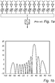
- each receive antenna element is a part of a respective channel, which additionally contains a controllable delay or phase shifter following the receive antenna element, as shown in Fig. 1 a.
- a controllable delay or phase shifter following the receive antenna element, as shown in Fig. 1 a.
- BW narrowband signals
- c 0 the speed of light
- D the width of the antenna
- phase shifters work good, otherwise a controllable delay must be implemented which becomes large and lossy for large antennas.
- the channel signals are summed together creating a beam as shown in Fig. 2 .
- the advantage of this solution is that it is rather cheap since the microwave receivers are needed anyway and one digital receiver is enough.
- the disadvantage is that only one beam can be synthesized simultaneously.
- Digital beamforming is another alternative.
- the delay, and thereby the beamforming can be done after sampling if each channel incorporates an A/D-converter, see Fig. 2a .
- the delaying and summing of the data, and hence the beamforming, is done strictly mathematically.
- the advantage using this solution is that several beams can be formed simultaneously, see Fig. 2b .
- the disadvantage is that the number of A/D-converters is large and they need to be synchronized. There is also a vast amount of data to handle, although this, per se, poses less of a problem in advanced signal processing ASICs.
- hybrid beamforming this is done by having phase shifters at microwave frequency and summing the channel signals in groups which are then sampled, as shown in Fig. 3a . This data can be used to form narrow beams within the wider beams formed by each group, as shown in Fig. 3b .
- a common drawback of the present AESAs is that the number of microwave receivers is defined by the antenna size, which means that for a narrow beam antenna the antenna is large and the numbers of microwave receivers is large.
- the number of microwave receivers and digital channels is to a large degree what is driving cost, power consumption and dimensioning of expensive cooling systems in traditional AESAs.
- a beamforming method for an active electronically steerable receive antenna which receive antenna comprises an antenna array containing several receive antenna elements, the method comprising:
- This beamforming method is advantageous in that is allows the receive antenna elements to be sparsely mounted, i.e. to be mounted with larger spacings than half a wavelength, while keeping the desired final beam pattern of a narrow main lobe and significantly suppressed grating lobes. Due to the sparse mounting, in comparison with the prior art receivers, the number of receive antenna elements, and thereby the cost and power dissipation, is reduced without losing performance.
- the present beamforming method can be used in any radar system where beamforming for a receiving antenna is to be used, although it is particularly useful for wideband FMCW radars due to their small baseband frequency.
- a wide transmit beam is used while the direction to a target is defined by having multiple narrow receive beams. These can be synthesized digitally after the A/D-conversion.
- a relation between the bandwidth of the radar signal and the width of the antenna preferably is such that the bandwidth is large enough to provide a distance resolution at least in the order of the width of the antenna.
- the method comprises determining the product beamforming signal by multiplying digital signals from receive antenna elements at opposite ends of the antenna array.
- the method comprises arranging the receive antenna elements at mutual distances exceeding ⁇ /2, where ⁇ is the wavelength of a carrier of the reflected radar signal.
- the receive processing further comprising transforming the digital signals to frequency domain before determining the beamformed signal.
- a range resolution of the radar beam is comparable with the width of the receive antenna.
- the width of a main lobe of a beam corresponding with the sum beamforming signal is narrower than the width of a main lobe of a beam corresponding with the product beamforming signal.
- the method comprises arranging at least two adjacent receive antenna elements at a mutual distance exceeding ⁇ , where ⁇ is the wavelength of a carrier of the reflected radar signal.
- the alignment is performed by aligning the digital signals in respect of arrival time of the corresponding received signals.
- an active electronically steerable receive antenna having an antenna array containing several receive antenna elements arranged to generate received signals, frequency down-converters, connected with the receive antenna elements, analog-to-digital converters, connected with the frequency down-converters, arranged to generate digital signals, and a beamforming device connected with the analog-to-digital converters, arranged to determine a beamformed signal by multiplying several signals including a sum beamforming signal, which is determined by summing at least two of the digital signals, and a product beamforming signal, which is determined by multiplying at least two of the digital signals, wherein the product beamforming signal is a grating lobe suppression signal, which suppresses grating lobes of the sum beamforming signal when multiplied with the sum beamforming signal.
- the receive antenna provides corresponding advantages as the method described above.
- the present invention is focused on the receiver part of a radar, and the transmitter part will therefore only be referred to in brief, since it has a common structure well known to the person skilled in the art.
- the receiver part can be designed according to different principles, such as the above-mentioned hybrid receiver having both analog and digital beamforming, or digital receiver. In the following description it is assumed that a digital receiver with the design shown in Fig. 4 is used.
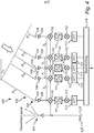
- Fig. 4 shows an embodiment of a portion 100 of an exemplifying radar apparatus, such as an FMCW radar, comprising a transmit antenna 101, which contains one or more transmit antenna elements, and a receiver device 102.
- the FMCW radar has an advantage compared with other radar types in that the sampling frequency, and thereby the amount of data, can be kept comparably low, which facilitates signal processing in each channel.
- the receiver device 102 performs a digital beamforming, or steering, and comprises a receive antenna 103, here exemplified by an array of several receive antenna elements 104, 105, 106, 107, 108 arranged in a single row. More particularly, in this example the antenna array contains five receive antenna elements 104-108.
- a first distance between the centre receive antenna element 106 and the adjacent receive antenna elements 105, 107 at both sides of the centre receive antenna element 106 is d 1
- a second distance between the centre receive antenna element 106 and the receive antenna elements 104, 108 at the respective ends of the receive antenna 103 is d 2 , as illustrated in Fig. 4 .
- the total width of the receive antenna 103 is 2d 2 .
- the receiver device 102 comprises a receive channel for each receive antenna element 104-108, where each receive channel comprises an amplifier 109 connected with the receive antenna element 104-108, a frequency down-converter, here a mixer, 110 connected with the amplifier 109, an analog-to-digital converter 111 connected with the mixer 110, an alignment element 112 connected with the analog-to-digital (A/D) converter 111, and a Fast Fourier Transform (FFT) unit 113.
- FFT Fast Fourier Transform
- the receiver device 102 further comprises a beamforming unit 114, which is connected to all FFT units 113 to receive their output FFT signals.
- the beamforming unit 114 generates the desired beam by combining summation and multiplication of the FFT signals as will be explained below.
- the receiver device 102 may comprise a further signal processing device connected to the output of the beamforming unit 114, but since such a further signal processing device does not form part of the basic inventive concept it has been omitted from this description.
- the receiver device could be regarded as comprising receive antenna elements, mixers, analog-to-digital converters and a beamforming unit. It should also be mentioned that it is understood by the person skilled in the art that the receiver device 102 may additionally comprise one or more filter units in each receive channel. Further, the frequency down-conversion can be made in several steps instead of in one step as exemplified herein.
- the FMCW radar in general, and in particular the receiver device 102, operates as follows.
- the transmitter device 101 transmits a radar signal the frequency of which follows a frequency ramp having two portions, i.e. a first portion and a following second portion.
- the first portion the frequency is ramped up from a lower start frequency to a higher end frequency, or vice versa, and during the second portion the frequency of the output signal is returned to the start frequency.
- the duration of the first and second portions can be equal but usually the duration of the second portion, also called resetting portion, is significantly shorter. This combination of portions is continuously repeated.
- the transmitted radar signal x tx (t) is reflected against a remote object, called a target.
- the reflected signal x rx (t) is received at the receive antenna 103 of the receiver device 102.
- the reflected signal is received at an angle ⁇ to the normal direction of the receive antenna elements 104-108.
- the receive antenna elements 104-108 output received signals x n (t) , where n denotes which receive antenna element 104-108 the received signal comes from, as illustrated in step 81 of Fig. 8 .
- the frequency and phase slightly differ between, and are unique, for each received signal x n (t).
- the received signals x n (t) are frequency down-converted by means of the mixers 110, and analog-to-digital converted by means of the A/D converters 111 to digital signals x' n (t), in step 82.
- the digital signals are aligned by means of the alignment elements 112, in step 83, and finally transformed to frequency domain, by means of the FFT units 113.
- the alignment is done due to the difference in arrival time of the reflected signal at the different receive antenna elements 104-108.
- the time difference corresponds with a frequency difference
- the alignment is performed by means of frequency shifting, such that all signals originating from the receive antenna elements 104-108 are aligned as regards their phase and frequency for a chosen angle of incidence ⁇ . Since this in practice, in this embodiment, is done by multiplying the received signals with alignment signals, the alignment elements 112 are illustrated with mixer symbols. In other embodiments though, and for other radar types, the alignment can be performed by means of a phase shift, etc. After alignment the digital signals are denoted y n (t, ⁇ 0 ), where ⁇ 0 is the desired centre angle of the beam.
- the digital signals are denoted Y n (f, ⁇ 0 ).
- the beamforming is performed by means of the FFT signals Y n (f, ⁇ 0 ) , i.e. by the digital signals in frequency domain, as follows. It should be noted that, as understood by the person skilled in the art, any frequency transform can be used, but the FFT is widely employed due to its relatively low complexity of calculations. Additionally, it should be noted that the below calculations for generating the beamformed signal could be done without frequency transforming the digital signals, i.e. in time domain, but at present that is less desired.
- the spacing between the antenna elements in an AESA is determined from the frequency and the amount of steering it should support. It shall preferably be less than half a wavelength of the carrier. Otherwise grating lobes will be generated due to the repetitive behavior of the microwave.
- the receive antenna 103 contains five receive antenna elements 104-108.
- the first distance d 1 1.5 ⁇
- the beams of the resulting FFT signals Y n (f, ⁇ 0 ) typically have a main lobe and grating lobes of significant magnitudes, even similar magnitudes as the main lobe, occurring too close to the main lobe. If using any of the common methods for beamforming, the grating lobes would not be suppressed to such an extent that the FFT signals Y n (f, ⁇ 0 ) would be very useful for the further signal processing, as has been thoroughly shown in prior art.
- a conventional receive antenna of the same size would have at least about 16 receive antenna elements instead of 5 to keep the spacing at ⁇ /2 or less.
- this problem is solved by a combination of summing and multiplying the digital signals, and more particularly the frequency transformed digital signals Y n (f, ⁇ 0 ). From left to right in Fig. 4 the FFT signals are denoted Y 1 (f, ⁇ 0 ) to Y 5 (f, ⁇ 0 ).
- the FFT signal determined on the receive signal from the end receive antenna element 104 at the left end of the receive antenna 103 is denoted Y 1 (f, ⁇ 0 )
- the FFT signal of the adjacent receive antenna element 105 to the right thereof is denoted Y 2 (f, ⁇ 0 )
- the FFT signal of the right most receive antenna element 108 which is denoted Y 5 (f, ⁇ 0 ).
- the FFT signals are aligned with respect to frequency and phase, and the alignment was made in the time domain. It would be possible to perform the alignment on the FFT signals instead. However, that is presently less preferred due to a higher calculation load. Furthermore, the alignment as such would be possible to perform already before down-converting the received signals, i.e. in RF state, by means of true-time delay circuits constituting the alignment elements. However, there are some drawbacks with such an arrangement.
- the determination of the beamformed signal includes the following steps. At least one sum beamforming signal is determined by summing at least two of the digital signals Y n (f, ⁇ 0 ) , in step 84. Further, at least one product beamforming signal is determined by multiplying at least two of the digital signals Y n (f, ⁇ 0 ) , in step 85. This includes that, if appropriate, one or more additional product beamforming signal can be determined by multiplying sum beamforming signals with each other. Finally, the beamformed signal is determined by multiplying one or more of the sum beamforming signals with one or more of the product beamforming signals, in step 86.
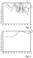
- the first sum beamforming signal S 1 has significant grating lobes.
- a second sum beamforming signal S 2 was calculated as the sum of the FFT signals of the three receive antenna elements 105, 106, 107 in the middle of the receive antenna 103, i.e.
- S 2 (f, ⁇ 0 ) Y 2 (f, ⁇ 0 ) + Y 3 (f, ⁇ 0 ) + Y 4 (f, ⁇ 0 ).
- the second sum beamforming signal S 2 has significant grating lobes as well, see Fig. 5 .
- a second product beamforming signal P 2 is calculated by multiplying the FFT signals of the end receive antenna elements 104, 108, i.e.
- the beam generated by the second product beamforming signal P 2 has a broad main lobe and significantly suppressed grating lobes.
- the third product signal is the resulting beamformed signal, which will be generally denoted as S tot ( f, ⁇ 0 ), that is output from the beamforming unit 114 for further signal processing. That further processing is commonly known as such to the person skilled in the art and therefore will not be further described herein.
- the beam pattern corresponding with the third product signal P 3 has a narrow main lobe and significantly suppressed grating lobes, as shown in Fig. 7 .
- at least one sum beamforming signal is determined by summing, for each sum beamforming signal, at least two of the digital signals
- at least one product beamforming signal is determined by multiplying, for each product beamforming signal, at least two of the digital signals.
- a beamformed signal i.e. the resulting signal, is generated by multiplying the at least one sum beamforming signal with the at least one product beamforming signal.
- one sum beamforming signal is multiplied with one product beamforming signal, while in the above example two sum beamforming signals were used. More sums and products can be determined to provide additional beamforming signals, which are all finally multiplied together to generate the beamformed signal.
- all FFT signals could be multiplied together, but that would cause an unnecessary burden of calculation.
- the beamformed signal is S 1 * P 1 .
- the calculations can be described as follows.
- a narrow beam can be formed with only few receive antenna elements, partly because the receive antenna elements can be positioned with large spacings, typically up to several wavelengths. This can reduce both cost, power dissipation and amount of data to be processed.
- the method is applicable to receive antennas having considerably more receive antenna elements than exemplified above as well, if desired to, for instance, design a wider receive antenna, or design a two-dimensional antenna.
- the receive antenna elements can be sparsely arranged with spacings larger than half a wavelength.
- the method is not dependent on the number of receive antenna elements, as long as they are at least two.
- an effect of the method is that irrespective of the physical size of the radar antenna, a fewer number of receive antenna elements than in a conventional antenna can be used, that is a larger spacing between the receive antenna elements can be applied.
Landscapes
- Engineering & Computer Science (AREA)
- Radar, Positioning & Navigation (AREA)
- Remote Sensing (AREA)
- Physics & Mathematics (AREA)
- Computer Networks & Wireless Communication (AREA)
- General Physics & Mathematics (AREA)
- Electromagnetism (AREA)
- Radar Systems Or Details Thereof (AREA)
- Variable-Direction Aerials And Aerial Arrays (AREA)
Abstract
Description
- The present invention relates to a radar beamforming method.
- In many applications where a radar, such as a continuous wave radar, e.g. FMCW (Frequency Modulated Continuous Wave) radar, or a pulsed radar, e.g. a MTI (Moving Target Indicator) radar, is used it is necessary to be able to form the beam of the transmitted radar signal as well as of the received radar signal in order to retrieve the desired information. Modern technologies have provided radar antennas which can generate beams in different directions without physically moving the antenna. That is, the antennas are electronically steerable. The present invention is related to signal processing of the received radar signal, i.e. the reflection of the transmitted radar signal. The traditional way to realize an Active Electronically Steerable Antenna (AESA), also called active electronically scanned array, is to have an array of receive antenna elements spaced by approximately half a wavelength of the received frequency. Each receive antenna element then has a circuit to delay the signal before the signals from the individual receive antenna elements are summed together. This is done in mainly three ways, as described below. As well known in the art, if the spacing of the receive antenna elements is less than half a wavelength this will provide the possibility to steer the antenna without getting grating lobes, i.e. significant beams forming in other directions than the desired one.
- One way of beamforming is called analog beamforming, where each receive antenna element is a part of a respective channel, which additionally contains a controllable delay or phase shifter following the receive antenna element, as shown in
Fig. 1 a. For narrowband signals, i.e. BW<<c0/D where BW is the bandwidth of the signal, c0 is the speed of light and D is the width of the antenna, phase shifters work good, otherwise a controllable delay must be implemented which becomes large and lossy for large antennas. After the phase shift/delay, the channel signals are summed together creating a beam as shown inFig. 2 . The advantage of this solution is that it is rather cheap since the microwave receivers are needed anyway and one digital receiver is enough. The disadvantage is that only one beam can be synthesized simultaneously. - Digital beamforming is another alternative. The delay, and thereby the beamforming, can be done after sampling if each channel incorporates an A/D-converter, see
Fig. 2a . This allows to look at several directions simultaneously since data for each channel signal is stored. The delaying and summing of the data, and hence the beamforming, is done strictly mathematically. The advantage using this solution is that several beams can be formed simultaneously, seeFig. 2b . However, it is only useful to form receive beams at angles that are covered by the transmit beam. The disadvantage is that the number of A/D-converters is large and they need to be synchronized. There is also a vast amount of data to handle, although this, per se, poses less of a problem in advanced signal processing ASICs. - Since the transmit beam of a radar is usually not very wide it is often enough to be able to form beams simultaneously within that beam. In yet another alternative solution, called hybrid beamforming, this is done by having phase shifters at microwave frequency and summing the channel signals in groups which are then sampled, as shown in
Fig. 3a . This data can be used to form narrow beams within the wider beams formed by each group, as shown inFig. 3b . - However, a common drawback of the present AESAs is that the number of microwave receivers is defined by the antenna size, which means that for a narrow beam antenna the antenna is large and the numbers of microwave receivers is large. The number of microwave receivers and digital channels is to a large degree what is driving cost, power consumption and dimensioning of expensive cooling systems in traditional AESAs.
- It would be advantageous to provide a solution that reduces the above-mentioned common drawback.
- To address this concern, in a first aspect of the invention there is presented a beamforming method for an active electronically steerable receive antenna, which receive antenna comprises an antenna array containing several receive antenna elements, the method comprising:
- receiving reflected radar signals at the receive antenna elements, and obtaining received signals from the receive antenna elements;
- receive processing the received signals, the receive processing comprising frequency down-conversion, and analog-to-digital conversion, thereby generating several digital signals;
- aligning the received signals or the digital signals for a predetermined angle of incidence; and
- determining a beamformed signal, comprising multiplying several signals including a sum beamforming signal, which is determined by summing at least two of the digital signals, and a product beamforming signal, which is determined by multiplying at least two of the digital signals, wherein the product beamforming signal is a grating lobe suppression signal, which suppresses grating lobes of the sum beamforming signal when multiplied with the sum beamforming signal.
- This beamforming method is advantageous in that is allows the receive antenna elements to be sparsely mounted, i.e. to be mounted with larger spacings than half a wavelength, while keeping the desired final beam pattern of a narrow main lobe and significantly suppressed grating lobes. Due to the sparse mounting, in comparison with the prior art receivers, the number of receive antenna elements, and thereby the cost and power dissipation, is reduced without losing performance.
- The present beamforming method can be used in any radar system where beamforming for a receiving antenna is to be used, although it is particularly useful for wideband FMCW radars due to their small baseband frequency. In many radar systems, e.g. surveillance radars, a wide transmit beam is used while the direction to a target is defined by having multiple narrow receive beams. These can be synthesized digitally after the A/D-conversion.
- For a good operation of the method a relation between the bandwidth of the radar signal and the width of the antenna preferably is such that the bandwidth is large enough to provide a distance resolution at least in the order of the width of the antenna.
- In accordance with an embodiment of the method it comprises determining the product beamforming signal by multiplying digital signals from receive antenna elements at opposite ends of the antenna array.
- In accordance with an embodiment of the method it comprises arranging the receive antenna elements at mutual distances exceeding λ/2, where λ is the wavelength of a carrier of the reflected radar signal.
- In accordance with an embodiment of the method the receive processing further comprising transforming the digital signals to frequency domain before determining the beamformed signal.
- In accordance with an embodiment of the method a range resolution of the radar beam is comparable with the width of the receive antenna.
- In accordance with an embodiment of the method the width of a main lobe of a beam corresponding with the sum beamforming signal is narrower than the width of a main lobe of a beam corresponding with the product beamforming signal.
- In accordance with an embodiment of the method it comprises arranging at least two adjacent receive antenna elements at a mutual distance exceeding λ, where λ is the wavelength of a carrier of the reflected radar signal.
- In accordance with an embodiment of the method the alignment is performed by aligning the digital signals in respect of arrival time of the corresponding received signals.
- According to another aspect of the invention there is provided an active electronically steerable receive antenna having an antenna array containing several receive antenna elements arranged to generate received signals, frequency down-converters, connected with the receive antenna elements, analog-to-digital converters, connected with the frequency down-converters, arranged to generate digital signals, and a beamforming device connected with the analog-to-digital converters, arranged to determine a beamformed signal by multiplying several signals including a sum beamforming signal, which is determined by summing at least two of the digital signals, and a product beamforming signal, which is determined by multiplying at least two of the digital signals, wherein the product beamforming signal is a grating lobe suppression signal, which suppresses grating lobes of the sum beamforming signal when multiplied with the sum beamforming signal. The receive antenna provides corresponding advantages as the method described above.
- The invention will now be described in more detail and with reference to the appended drawings in which:
-
Figs. 1a-3b illustrates prior art; -
Fig. 4 is a schematic block diagram showing an embodiment of a receiver structure according to the present invention; -
Figs. 5-7 are diagrams illustrating beam patterns, and -
Fig. 8 is a flow chart illustrating an embodiment of the method according to the present invention. - The present invention is focused on the receiver part of a radar, and the transmitter part will therefore only be referred to in brief, since it has a common structure well known to the person skilled in the art. The receiver part can be designed according to different principles, such as the above-mentioned hybrid receiver having both analog and digital beamforming, or digital receiver. In the following description it is assumed that a digital receiver with the design shown in
Fig. 4 is used. -
Fig. 4 shows an embodiment of aportion 100 of an exemplifying radar apparatus, such as an FMCW radar, comprising a transmitantenna 101, which contains one or more transmit antenna elements, and areceiver device 102. The FMCW radar has an advantage compared with other radar types in that the sampling frequency, and thereby the amount of data, can be kept comparably low, which facilitates signal processing in each channel. Thereceiver device 102 performs a digital beamforming, or steering, and comprises a receiveantenna 103, here exemplified by an array of several receiveantenna elements antenna element 106 and the adjacent receiveantenna elements antenna element 106 is d1, and a second distance between the centre receiveantenna element 106 and the receiveantenna elements antenna 103 is d2, as illustrated inFig. 4 . Thus, the total width of the receiveantenna 103 is 2d2. Thereceiver device 102 comprises a receive channel for each receive antenna element 104-108, where each receive channel comprises anamplifier 109 connected with the receive antenna element 104-108, a frequency down-converter, here a mixer, 110 connected with theamplifier 109, an analog-to-digital converter 111 connected with themixer 110, analignment element 112 connected with the analog-to-digital (A/D)converter 111, and a Fast Fourier Transform (FFT)unit 113. For purposes of definition, such as in claim drafting, and for overall understanding, it should be noted that theamplifiers 109 can be regarded as included in the receive antenna elements 104-108, and also other combinations are possible as understood by the person skilled in the art. Similarly, other commonly used circuit components necessary for the function as a whole are of course included even if they are not explicitly shown in the drawings or mentioned in the description. Only those components relevant for describing the invention are disclosed. Thereceiver device 102 further comprises a beamforming unit 114, which is connected to allFFT units 113 to receive their output FFT signals. The beamforming unit 114 generates the desired beam by combining summation and multiplication of the FFT signals as will be explained below. As will be readily understood by the person skilled in the art, thereceiver device 102 may comprise a further signal processing device connected to the output of the beamforming unit 114, but since such a further signal processing device does not form part of the basic inventive concept it has been omitted from this description. - It should be mentioned that in its most simplified configuration the receiver device could be regarded as comprising receive antenna elements, mixers, analog-to-digital converters and a beamforming unit. It should also be mentioned that it is understood by the person skilled in the art that the
receiver device 102 may additionally comprise one or more filter units in each receive channel. Further, the frequency down-conversion can be made in several steps instead of in one step as exemplified herein. - The FMCW radar in general, and in particular the
receiver device 102, operates as follows. Thetransmitter device 101 transmits a radar signal the frequency of which follows a frequency ramp having two portions, i.e. a first portion and a following second portion. During the first portion the frequency is ramped up from a lower start frequency to a higher end frequency, or vice versa, and during the second portion the frequency of the output signal is returned to the start frequency. The duration of the first and second portions can be equal but usually the duration of the second portion, also called resetting portion, is significantly shorter. This combination of portions is continuously repeated. There are many shapes of the ramp that are used, such as continuous increase/decrease, discontinuous, e.g. stepwise, increase/decrease, etc. The transmitted radar signal xtx(t) is reflected against a remote object, called a target. The reflected signal xrx(t) is received at the receiveantenna 103 of thereceiver device 102. Typically, the reflected signal is received at an angle θ to the normal direction of the receive antenna elements 104-108. The receive antenna elements 104-108 output received signals xn(t), where n denotes which receive antenna element 104-108 the received signal comes from, as illustrated instep 81 ofFig. 8 . As understood by the person skilled in the art, due to distance differences between the reflecting object and the receive antenna elements 104-108 the frequency and phase slightly differ between, and are unique, for each received signal xn(t). The received signals xn(t) are frequency down-converted by means of themixers 110, and analog-to-digital converted by means of the A/D converters 111 to digital signals x'n(t), instep 82. The digital signals are aligned by means of thealignment elements 112, instep 83, and finally transformed to frequency domain, by means of theFFT units 113. The alignment is done due to the difference in arrival time of the reflected signal at the different receive antenna elements 104-108. It should however be noted that in this embodiment, with an FMCW radar, the time difference corresponds with a frequency difference, and therefore the alignment is performed by means of frequency shifting, such that all signals originating from the receive antenna elements 104-108 are aligned as regards their phase and frequency for a chosen angle of incidence θ. Since this in practice, in this embodiment, is done by multiplying the received signals with alignment signals, thealignment elements 112 are illustrated with mixer symbols. In other embodiments though, and for other radar types, the alignment can be performed by means of a phase shift, etc. After alignment the digital signals are denoted yn(t, θ0), where θ0 is the desired centre angle of the beam. When output from theFFT units 113 the digital signals are denoted Yn(f, θ0). The beamforming is performed by means of the FFT signals Yn(f, θ0), i.e. by the digital signals in frequency domain, as follows. It should be noted that, as understood by the person skilled in the art, any frequency transform can be used, but the FFT is widely employed due to its relatively low complexity of calculations. Additionally, it should be noted that the below calculations for generating the beamformed signal could be done without frequency transforming the digital signals, i.e. in time domain, but at present that is less desired. - The spacing between the antenna elements in an AESA is determined from the frequency and the amount of steering it should support. It shall preferably be less than half a wavelength of the carrier. Otherwise grating lobes will be generated due to the repetitive behavior of the microwave. In this embodiment, as mentioned above, it is assumed that the receive
antenna 103 contains five receive antenna elements 104-108. Unlike the prior art and in contrast to the conventional way of designing the ASEA, in this embodiment the first distance d1=1.5λ, and the second distance d2=4.5λ, where λ is the wavelength of the carrier. This means that the distance between the respective end receiveantenna element antenna element - However, in accordance with the present embodiment, this problem is solved by a combination of summing and multiplying the digital signals, and more particularly the frequency transformed digital signals Yn(f, θ0). From left to right in
Fig. 4 the FFT signals are denoted Y1(f, θ0) to Y5(f, θ0). In other words, the FFT signal determined on the receive signal from the end receiveantenna element 104 at the left end of the receiveantenna 103 is denoted Y1(f, θ0), the FFT signal of the adjacent receiveantenna element 105 to the right thereof is denoted Y2(f, θ0), and so on to the FFT signal of the right most receiveantenna element 108, which is denoted Y5(f, θ0). As described above, the FFT signals are aligned with respect to frequency and phase, and the alignment was made in the time domain. It would be possible to perform the alignment on the FFT signals instead. However, that is presently less preferred due to a higher calculation load. Furthermore, the alignment as such would be possible to perform already before down-converting the received signals, i.e. in RF state, by means of true-time delay circuits constituting the alignment elements. However, there are some drawbacks with such an arrangement. - Generally expressed, the determination of the beamformed signal includes the following steps. At least one sum beamforming signal is determined by summing at least two of the digital signals Yn(f, θ0), in
step 84. Further, at least one product beamforming signal is determined by multiplying at least two of the digital signals Yn(f, θ0), instep 85. This includes that, if appropriate, one or more additional product beamforming signal can be determined by multiplying sum beamforming signals with each other. Finally, the beamformed signal is determined by multiplying one or more of the sum beamforming signals with one or more of the product beamforming signals, instep 86. - A simulation where the reflecting target was not moving, i.e. without any Doppler frequency deviation, and with a non-significant noise level, was performed. The resulting FFT signals was summed and multiplied as will be described below, rendering the intermediate and final beam patterns as shown in
Figs. 5-7 , where the reflection angle θ in degrees is represented at the x axis, and the suppression in dB is represented at the y axis. - A first sum beamforming signal S1 was calculated as the sum of the FFT signals of the end receive
antenna elements antenna element 106, i.e. S1(f, θ0)=Y1(f, θ0)+Y3(f, θ0)+Y5(f, θ0), seeFig. 5 . The first sum beamforming signal S1 has significant grating lobes. A second sum beamforming signal S2 was calculated as the sum of the FFT signals of the three receiveantenna elements antenna 103, i.e. S2(f, θ0)=Y2(f, θ0)+Y3(f, θ0)+Y4(f, θ0). The second sum beamforming signal S2 has significant grating lobes as well, seeFig. 5 . Further, a first product beamforming signal P1(f, θ0) was calculated by multiplying the first and second sum beamforming signals with each other, i.e. P1 =S1 *S2 , generating a beam having a narrow main lobe and slightly to significantly suppressed grating lobes. A second product beamforming signal P2 is calculated by multiplying the FFT signals of the end receiveantenna elements Fig. 6 . The beam generated by the second product beamforming signal P2 has a broad main lobe and significantly suppressed grating lobes. By multiplying the sum and second product beamforming signals a third product beamforming signal P3 = P1 *P2 is generated, seeFig. 7 . The third product signal is the resulting beamformed signal, which will be generally denoted as Stot (f,θ 0), that is output from the beamforming unit 114 for further signal processing. That further processing is commonly known as such to the person skilled in the art and therefore will not be further described herein. The beam pattern corresponding with the third product signal P3 has a narrow main lobe and significantly suppressed grating lobes, as shown inFig. 7 . More generally expressed, at least one sum beamforming signal is determined by summing, for each sum beamforming signal, at least two of the digital signals, and at least one product beamforming signal is determined by multiplying, for each product beamforming signal, at least two of the digital signals. Finally, a beamformed signal, i.e. the resulting signal, is generated by multiplying the at least one sum beamforming signal with the at least one product beamforming signal. Thus, in the simplest case, one sum beamforming signal is multiplied with one product beamforming signal, while in the above example two sum beamforming signals were used. More sums and products can be determined to provide additional beamforming signals, which are all finally multiplied together to generate the beamformed signal. As a further example all FFT signals could be multiplied together, but that would cause an unnecessary burden of calculation. - As an alternative to the example above the following calculations could be made for the same example of five receive antenna elements 104-108. A first sum beamforming signal is determined as S1 = Y1 + Y2 + Y3 + Y4 + Y5, a first product beamforming signal is determined as P1 = Y1 * Y1, and the beamformed signal as Stot = S1 *P1. Introducing mathematical expressions for the signals, the calculations can be described as follows. For the exemplifying FMCW radar, the transmitted signal can be represented by xt(t) as


antenna 103. R n is the additional distance to the respective receive antenna element 104-108, which is dependent on the incident angle θ, such that R 0=d n sin θ, where d n is the lateral distance between the reference point and the respective receive antenna element 104-108. After A/D conversion the digital signals are:


- The sum beamforming signals and the product beamforming signals can be expressed as


- It can be noted that for reflection angles θ≠θ0 the amplitude of the sum signals Sn (f,θ 0) changes fast when θ changes, but the high amplitude repeats itself due to the periodicity leading to significant grating lobes. On the other hand, the amplitude of the product signals Pn(f,θ 0) changes slow when θ changes and the high amplitude does not repeat itself.
- As evident from the above example it is possible to form a very narrow beam with only five receive antenna elements 104-108. However, the method is based on some requisites to work well. The relative bandwidth BWrel=BW/f0 of the transmitted/reflected signal should be large. If the relative bandwidth is large one can use the frequency difference over the antenna due to difference in distance to the target to form a wide beam without grating lobes. This is possible if the range resolution is comparable to the size of the antenna. As an example, the following figures have been used. Carrier frequency f0 =60 GHz; width of receive antenna D=9λ0 =45mm; Absolute bandwidth BWabs =6GHz; range resolution r≈c0 /BWabs =50mm. However, the method is of course applicable to any carrier frequency in the microwave band.
- Consequently, by combining the range resolution given from a large bandwidth together with the beamforming according to the present method, a narrow beam can be formed with only few receive antenna elements, partly because the receive antenna elements can be positioned with large spacings, typically up to several wavelengths. This can reduce both cost, power dissipation and amount of data to be processed. As understood by the person skilled in the art, the method is applicable to receive antennas having considerably more receive antenna elements than exemplified above as well, if desired to, for instance, design a wider receive antenna, or design a two-dimensional antenna. However, also in these cases the receive antenna elements can be sparsely arranged with spacings larger than half a wavelength.
- While the invention has been illustrated and described in detail in the drawings and foregoing description, such illustration and description are to be considered illustrative or exemplary and not restrictive; the invention is not limited to the disclosed embodiments.
- For instance, the method is not dependent on the number of receive antenna elements, as long as they are at least two. As explained above, an effect of the method is that irrespective of the physical size of the radar antenna, a fewer number of receive antenna elements than in a conventional antenna can be used, that is a larger spacing between the receive antenna elements can be applied.
- Other variations to the disclosed embodiments can be understood and effected by those skilled in the art in practicing the claimed invention, from a study of the drawings, the disclosure, and the appended claims. In the claims, the word "comprising" does not exclude other elements or steps, and the indefinite article "a" or "an" does not exclude a plurality. A single processor or other unit may fulfill the functions of several items recited in the claims. The mere fact that certain measures are recited in mutually different dependent claims does not indicate that a combination of these measured cannot be used to advantage. Any reference signs in the claims should not be construed as limiting the scope.
Claims (10)
Priority Applications (4)
| Application Number | Priority Date | Filing Date | Title |
|---|---|---|---|
| EP18154523.7A EP3521852B1 (en) | 2018-01-31 | 2018-01-31 | Radar beamforming method |
| JP2019008418A JP7502848B2 (en) | 2018-01-31 | 2019-01-22 | Radar beamforming method |
| CN201910082111.4A CN110095771B (en) | 2018-01-31 | 2019-01-28 | Radar beamforming method |
| US16/262,670 US11133585B2 (en) | 2018-01-31 | 2019-01-30 | Radar beamforming |
Applications Claiming Priority (1)
| Application Number | Priority Date | Filing Date | Title |
|---|---|---|---|
| EP18154523.7A EP3521852B1 (en) | 2018-01-31 | 2018-01-31 | Radar beamforming method |
Publications (2)
| Publication Number | Publication Date |
|---|---|
| EP3521852A1 true EP3521852A1 (en) | 2019-08-07 |
| EP3521852B1 EP3521852B1 (en) | 2021-07-14 |
Family
ID=61132221
Family Applications (1)
| Application Number | Title | Priority Date | Filing Date |
|---|---|---|---|
| EP18154523.7A Active EP3521852B1 (en) | 2018-01-31 | 2018-01-31 | Radar beamforming method |
Country Status (4)
| Country | Link |
|---|---|
| US (1) | US11133585B2 (en) |
| EP (1) | EP3521852B1 (en) |
| JP (1) | JP7502848B2 (en) |
| CN (1) | CN110095771B (en) |
Cited By (1)
| Publication number | Priority date | Publication date | Assignee | Title |
|---|---|---|---|---|
| CN113777574A (en) * | 2021-08-30 | 2021-12-10 | 深圳市道通智能汽车有限公司 | Sparse array grating lobe solution method, device and related equipment |
Families Citing this family (6)
| Publication number | Priority date | Publication date | Assignee | Title |
|---|---|---|---|---|
| JP6928266B2 (en) * | 2018-05-28 | 2021-09-01 | 日本電信電話株式会社 | Underground radar device |
| CN110609279B (en) * | 2019-09-25 | 2022-11-04 | 上海保隆汽车科技股份有限公司 | Algorithm for optimizing angle grating lobe problem |
| JP7413858B2 (en) * | 2020-03-16 | 2024-01-16 | 株式会社デンソー | ranging module |
| EP3910814A1 (en) * | 2020-05-14 | 2021-11-17 | Nxp B.V. | Antenna system and method of operating an antenna system |
| DE102020125110A1 (en) * | 2020-09-25 | 2022-05-19 | Infineon Technologies Ag | METHOD OF TREATMENT OF RADAR SIGNALS OF A RADAR SYSTEM AND RADAR SYSTEM |
| CN114361814B (en) * | 2022-01-18 | 2023-06-20 | 中国电子科技集团公司第十研究所 | A phased array antenna with sidelobe suppressed beam, system and method of use thereof |
Citations (1)
| Publication number | Priority date | Publication date | Assignee | Title |
|---|---|---|---|---|
| DE10036132A1 (en) * | 2000-07-25 | 2002-02-07 | Volkswagen Ag | Vehicle mounted radar sensor signal processing method involves determining output signal of radar sensors by calculating differences of signals of filled and thinned out subarrays |
Family Cites Families (30)
| Publication number | Priority date | Publication date | Assignee | Title |
|---|---|---|---|---|
| US5434576A (en) * | 1994-02-23 | 1995-07-18 | The United States Of America As Represented By The Secretary Of The Air Force | Optimized subarray amplitude tapers for array antennas |
| US5481270A (en) * | 1994-03-04 | 1996-01-02 | Martin Marietta Corporation | Radar with adaptive range sidelobe suppression |
| CA2157139A1 (en) * | 1994-09-01 | 1996-03-02 | Thomas C. Weakley | Multiple beam antenna system for simultaneously receiving multiple satellite signals |
| AU2001282275A1 (en) * | 2000-08-11 | 2002-02-25 | Alenia Marconi Systems Limited | Method of interference suppression in a radar system |
| ATE317549T1 (en) * | 2001-03-15 | 2006-02-15 | SIDE VIEW RADAR SYSTEM WITH SYNTHETIC APERTURE | |
| JP2003008483A (en) * | 2001-06-18 | 2003-01-10 | Nec Corp | Adaptive array antenna receiver |
| US6496158B1 (en) * | 2001-10-01 | 2002-12-17 | The Aerospace Corporation | Intermodulation grating lobe suppression method |
| KR100604822B1 (en) * | 2003-07-03 | 2006-07-28 | 삼성전자주식회사 | Wireless fading channel demodulator providing beamforming and diversity gain using sub-array grouped adaptive array antennas, mobile communication receiving system and method thereof |
| JP4447946B2 (en) * | 2004-03-22 | 2010-04-07 | 富士通テン株式会社 | Radar equipment |
| DE102004059915A1 (en) * | 2004-12-13 | 2006-06-14 | Robert Bosch Gmbh | radar system |
| US20080068266A1 (en) * | 2005-11-23 | 2008-03-20 | Northrop Grumman Corporation | Beamforming for spatial sidelobe cancellation and AMR direction finding |
| JP4545174B2 (en) * | 2007-06-11 | 2010-09-15 | 三菱電機株式会社 | Radar equipment |
| US7705761B2 (en) * | 2007-11-07 | 2010-04-27 | Lockheed Martin Corporation | System and method for wideband direct sampling and beamforming using complex analog to digital converter |
| GB2458900A (en) * | 2008-03-31 | 2009-10-07 | Ubidyne Inc | Method and apparatus for suppression of sidelobes in antenna arrays |
| JP2010281791A (en) * | 2009-06-08 | 2010-12-16 | Toshiba Corp | Radar equipment |
| US8466829B1 (en) * | 2009-09-14 | 2013-06-18 | Lockheed Martin Corporation | Super-angular and range-resolution with phased array antenna and multifrequency dither |
| JP5093298B2 (en) * | 2010-06-04 | 2012-12-12 | 株式会社デンソー | Direction detection device |
| EP2403067A1 (en) * | 2010-06-23 | 2012-01-04 | Astrium Limited | An antenna |
| CN102082591A (en) * | 2010-12-13 | 2011-06-01 | 武汉滨湖电子有限责任公司 | Method for forming circular array antenna digital wave beams |
| US9535151B2 (en) * | 2011-12-28 | 2017-01-03 | Hrl Laboratories, Llc | Coded aperture beam analysis method and apparatus |
| JP6130116B2 (en) | 2012-09-20 | 2017-05-17 | 日本無線株式会社 | Receiving array antenna device |
| KR101477909B1 (en) | 2013-06-03 | 2014-12-30 | 주식회사 만도 | Radar apparatus and antenna apparatus |
| IL226992A (en) * | 2013-06-17 | 2017-11-30 | Elta Systems Ltd | System and method for receiving and processing array antenna signals |
| WO2015085120A1 (en) * | 2013-12-06 | 2015-06-11 | Lynch Jonathan J | Methods and apparatus for processing coded aperture radar (car) signals |
| JP2015141041A (en) | 2014-01-27 | 2015-08-03 | 三菱電機株式会社 | antenna device |
| JP5925264B2 (en) | 2014-09-10 | 2016-05-25 | 三菱電機株式会社 | Radar equipment |
| KR102449214B1 (en) * | 2015-05-13 | 2022-09-30 | 주식회사 에이치엘클레무브 | Apparatus for estimating angle of arrival and method for estimating angle of arrival using same |
| JP6289785B2 (en) * | 2016-01-29 | 2018-03-07 | 三菱電機株式会社 | Antenna device and method for reducing grating lobe |
| CN106093931B (en) * | 2016-05-31 | 2018-11-09 | 西安电子科技大学 | Radar-Communication Integrated receiving/transmission method based on digital array antenna |
| US10712438B2 (en) * | 2017-08-15 | 2020-07-14 | Honeywell International Inc. | Radar using personal phone, tablet, PC for display and interaction |
-
2018
- 2018-01-31 EP EP18154523.7A patent/EP3521852B1/en active Active
-
2019
- 2019-01-22 JP JP2019008418A patent/JP7502848B2/en active Active
- 2019-01-28 CN CN201910082111.4A patent/CN110095771B/en active Active
- 2019-01-30 US US16/262,670 patent/US11133585B2/en active Active
Patent Citations (1)
| Publication number | Priority date | Publication date | Assignee | Title |
|---|---|---|---|---|
| DE10036132A1 (en) * | 2000-07-25 | 2002-02-07 | Volkswagen Ag | Vehicle mounted radar sensor signal processing method involves determining output signal of radar sensors by calculating differences of signals of filled and thinned out subarrays |
Non-Patent Citations (2)
| Title |
|---|
| METZ C ET AL: "Performance of thinned antenna arrays using nonlinear processing in DBF radar applications", 2001 IEEE MTT-S INTERNATIONAL MICROWAVE SYMPOSIUM DIGEST.(IMS 2001). PHOENIX, AZ, MAY 20 - 25, 2001; [IEEE MTT-S INTERNATIONAL MICROWAVE SYMPOSIUM], NEW YORK, NY : IEEE, US, 20 May 2001 (2001-05-20), pages 275 - 278vol.1, XP032405507, ISBN: 978-0-7803-6538-4, DOI: 10.1109/MWSYM.2001.966887 * |
| TIMOTHY J BROCKETT ET AL: "Subarray Design Diagnostics for the Suppression of Undesirable Grating Lobes", IEEE TRANSACTIONS ON ANTENNAS AND PROPAGATION, IEEE SERVICE CENTER, PISCATAWAY, NJ, US, vol. 60, no. 3, 1 March 2012 (2012-03-01), pages 1373 - 1380, XP011429010, ISSN: 0018-926X, DOI: 10.1109/TAP.2011.2180333 * |
Cited By (1)
| Publication number | Priority date | Publication date | Assignee | Title |
|---|---|---|---|---|
| CN113777574A (en) * | 2021-08-30 | 2021-12-10 | 深圳市道通智能汽车有限公司 | Sparse array grating lobe solution method, device and related equipment |
Also Published As
| Publication number | Publication date |
|---|---|
| EP3521852B1 (en) | 2021-07-14 |
| US20190237871A1 (en) | 2019-08-01 |
| CN110095771B (en) | 2023-02-17 |
| US11133585B2 (en) | 2021-09-28 |
| JP7502848B2 (en) | 2024-06-19 |
| CN110095771A (en) | 2019-08-06 |
| JP2019168444A (en) | 2019-10-03 |
Similar Documents
| Publication | Publication Date | Title |
|---|---|---|
| US11133585B2 (en) | Radar beamforming | |
| US12222437B2 (en) | Radar device | |
| US9070972B2 (en) | Wideband beam forming device; wideband beam steering device and corresponding methods | |
| EP3021132B1 (en) | Mimo radar system | |
| CN104011558B (en) | The aperture beams analysis method of coding and equipment | |
| CN111090080B (en) | Ultra-wideband radar single-channel digital beam forming method based on space-time coding array | |
| CN111880171B (en) | A Pulse Segment Encoding Method for Eliminating Blind Velocity of Radar Targets | |
| KR100749560B1 (en) | Radar apparatus | |
| US20140062763A1 (en) | Radar device | |
| EP2798370A2 (en) | Coded aperture beam analysis method and apparatus | |
| US10928500B2 (en) | Distributed clutter motion suppression through multiple moving transmit phase centers | |
| EP4016127A1 (en) | Multiple input multiple steered output (mimso) radar | |
| US11509385B1 (en) | Angle diversity multiple input multiple output radar | |
| Hamidi et al. | CDM based virtual FMCW MIMO radar imaging at 79 GHz | |
| US10209353B2 (en) | Bandwidth enhancement beamforming | |
| CN113238212B (en) | Space-time coding-based frequency diversity array radar range resolution enhancement method | |
| RU2516683C9 (en) | Active phased antenna array digital beamforming method when emitting and receiving chirp signal | |
| Hussain | Performance analysis of space-time array processing using ultrawideband-throb signals for high-resolution imaging | |
| Akita et al. | Development of millimeter wave radar using stepped multiple frequency Complementary Phase Code and concept of MIMO configuration | |
| KR102478751B1 (en) | Estimation device of radar direction of arrival based on time division analog to digital converter, and method thereof | |
| Lim et al. | Shifting MIMO SAR system for high-resolution wide-swath imaging | |
| Akita et al. | Angle estimation using super resolution and blocking matrix in stepped multiple frequency complementary phase code radar | |
| JP2025185281A (en) | Receiving device and radar device | |
| JPS63187180A (en) | Holographic radar | |
| Lathiya et al. | Digital matched filtering based on-board radar signal processing |
Legal Events
| Date | Code | Title | Description |
|---|---|---|---|
| PUAI | Public reference made under article 153(3) epc to a published international application that has entered the european phase |
Free format text: ORIGINAL CODE: 0009012 |
|
| STAA | Information on the status of an ep patent application or granted ep patent |
Free format text: STATUS: THE APPLICATION HAS BEEN PUBLISHED |
|
| AK | Designated contracting states |
Kind code of ref document: A1 Designated state(s): AL AT BE BG CH CY CZ DE DK EE ES FI FR GB GR HR HU IE IS IT LI LT LU LV MC MK MT NL NO PL PT RO RS SE SI SK SM TR |
|
| AX | Request for extension of the european patent |
Extension state: BA ME |
|
| STAA | Information on the status of an ep patent application or granted ep patent |
Free format text: STATUS: REQUEST FOR EXAMINATION WAS MADE |
|
| 17P | Request for examination filed |
Effective date: 20200207 |
|
| RBV | Designated contracting states (corrected) |
Designated state(s): AL AT BE BG CH CY CZ DE DK EE ES FI FR GB GR HR HU IE IS IT LI LT LU LV MC MK MT NL NO PL PT RO RS SE SI SK SM TR |
|
| GRAP | Despatch of communication of intention to grant a patent |
Free format text: ORIGINAL CODE: EPIDOSNIGR1 |
|
| STAA | Information on the status of an ep patent application or granted ep patent |
Free format text: STATUS: GRANT OF PATENT IS INTENDED |
|
| INTG | Intention to grant announced |
Effective date: 20210311 |
|
| RAP3 | Party data changed (applicant data changed or rights of an application transferred) |
Owner name: SIVERS WIRELESS AB |
|
| GRAS | Grant fee paid |
Free format text: ORIGINAL CODE: EPIDOSNIGR3 |
|
| GRAA | (expected) grant |
Free format text: ORIGINAL CODE: 0009210 |
|
| STAA | Information on the status of an ep patent application or granted ep patent |
Free format text: STATUS: THE PATENT HAS BEEN GRANTED |
|
| AK | Designated contracting states |
Kind code of ref document: B1 Designated state(s): AL AT BE BG CH CY CZ DE DK EE ES FI FR GB GR HR HU IE IS IT LI LT LU LV MC MK MT NL NO PL PT RO RS SE SI SK SM TR |
|
| REG | Reference to a national code |
Ref country code: GB Ref legal event code: FG4D |
|
| REG | Reference to a national code |
Ref country code: IE Ref legal event code: FG4D |
|
| REG | Reference to a national code |
Ref country code: DE Ref legal event code: R096 Ref document number: 602018019932 Country of ref document: DE |
|
| REG | Reference to a national code |
Ref country code: AT Ref legal event code: REF Ref document number: 1411093 Country of ref document: AT Kind code of ref document: T Effective date: 20210815 |
|
| REG | Reference to a national code |
Ref country code: LT Ref legal event code: MG9D |
|
| REG | Reference to a national code |
Ref country code: NL Ref legal event code: MP Effective date: 20210714 |
|
| REG | Reference to a national code |
Ref country code: AT Ref legal event code: MK05 Ref document number: 1411093 Country of ref document: AT Kind code of ref document: T Effective date: 20210714 |
|
| PG25 | Lapsed in a contracting state [announced via postgrant information from national office to epo] |
Ref country code: NL Free format text: LAPSE BECAUSE OF FAILURE TO SUBMIT A TRANSLATION OF THE DESCRIPTION OR TO PAY THE FEE WITHIN THE PRESCRIBED TIME-LIMIT Effective date: 20210714 Ref country code: NO Free format text: LAPSE BECAUSE OF FAILURE TO SUBMIT A TRANSLATION OF THE DESCRIPTION OR TO PAY THE FEE WITHIN THE PRESCRIBED TIME-LIMIT Effective date: 20211014 Ref country code: PT Free format text: LAPSE BECAUSE OF FAILURE TO SUBMIT A TRANSLATION OF THE DESCRIPTION OR TO PAY THE FEE WITHIN THE PRESCRIBED TIME-LIMIT Effective date: 20211115 Ref country code: BG Free format text: LAPSE BECAUSE OF FAILURE TO SUBMIT A TRANSLATION OF THE DESCRIPTION OR TO PAY THE FEE WITHIN THE PRESCRIBED TIME-LIMIT Effective date: 20211014 Ref country code: AT Free format text: LAPSE BECAUSE OF FAILURE TO SUBMIT A TRANSLATION OF THE DESCRIPTION OR TO PAY THE FEE WITHIN THE PRESCRIBED TIME-LIMIT Effective date: 20210714 Ref country code: LT Free format text: LAPSE BECAUSE OF FAILURE TO SUBMIT A TRANSLATION OF THE DESCRIPTION OR TO PAY THE FEE WITHIN THE PRESCRIBED TIME-LIMIT Effective date: 20210714 Ref country code: SE Free format text: LAPSE BECAUSE OF FAILURE TO SUBMIT A TRANSLATION OF THE DESCRIPTION OR TO PAY THE FEE WITHIN THE PRESCRIBED TIME-LIMIT Effective date: 20210714 Ref country code: RS Free format text: LAPSE BECAUSE OF FAILURE TO SUBMIT A TRANSLATION OF THE DESCRIPTION OR TO PAY THE FEE WITHIN THE PRESCRIBED TIME-LIMIT Effective date: 20210714 Ref country code: ES Free format text: LAPSE BECAUSE OF FAILURE TO SUBMIT A TRANSLATION OF THE DESCRIPTION OR TO PAY THE FEE WITHIN THE PRESCRIBED TIME-LIMIT Effective date: 20210714 Ref country code: FI Free format text: LAPSE BECAUSE OF FAILURE TO SUBMIT A TRANSLATION OF THE DESCRIPTION OR TO PAY THE FEE WITHIN THE PRESCRIBED TIME-LIMIT Effective date: 20210714 Ref country code: HR Free format text: LAPSE BECAUSE OF FAILURE TO SUBMIT A TRANSLATION OF THE DESCRIPTION OR TO PAY THE FEE WITHIN THE PRESCRIBED TIME-LIMIT Effective date: 20210714 |
|
| PG25 | Lapsed in a contracting state [announced via postgrant information from national office to epo] |
Ref country code: PL Free format text: LAPSE BECAUSE OF FAILURE TO SUBMIT A TRANSLATION OF THE DESCRIPTION OR TO PAY THE FEE WITHIN THE PRESCRIBED TIME-LIMIT Effective date: 20210714 Ref country code: LV Free format text: LAPSE BECAUSE OF FAILURE TO SUBMIT A TRANSLATION OF THE DESCRIPTION OR TO PAY THE FEE WITHIN THE PRESCRIBED TIME-LIMIT Effective date: 20210714 Ref country code: GR Free format text: LAPSE BECAUSE OF FAILURE TO SUBMIT A TRANSLATION OF THE DESCRIPTION OR TO PAY THE FEE WITHIN THE PRESCRIBED TIME-LIMIT Effective date: 20211015 |
|
| REG | Reference to a national code |
Ref country code: DE Ref legal event code: R097 Ref document number: 602018019932 Country of ref document: DE |
|
| PG25 | Lapsed in a contracting state [announced via postgrant information from national office to epo] |
Ref country code: DK Free format text: LAPSE BECAUSE OF FAILURE TO SUBMIT A TRANSLATION OF THE DESCRIPTION OR TO PAY THE FEE WITHIN THE PRESCRIBED TIME-LIMIT Effective date: 20210714 |
|
| PLBE | No opposition filed within time limit |
Free format text: ORIGINAL CODE: 0009261 |
|
| STAA | Information on the status of an ep patent application or granted ep patent |
Free format text: STATUS: NO OPPOSITION FILED WITHIN TIME LIMIT |
|
| PG25 | Lapsed in a contracting state [announced via postgrant information from national office to epo] |
Ref country code: SM Free format text: LAPSE BECAUSE OF FAILURE TO SUBMIT A TRANSLATION OF THE DESCRIPTION OR TO PAY THE FEE WITHIN THE PRESCRIBED TIME-LIMIT Effective date: 20210714 Ref country code: SK Free format text: LAPSE BECAUSE OF FAILURE TO SUBMIT A TRANSLATION OF THE DESCRIPTION OR TO PAY THE FEE WITHIN THE PRESCRIBED TIME-LIMIT Effective date: 20210714 Ref country code: RO Free format text: LAPSE BECAUSE OF FAILURE TO SUBMIT A TRANSLATION OF THE DESCRIPTION OR TO PAY THE FEE WITHIN THE PRESCRIBED TIME-LIMIT Effective date: 20210714 Ref country code: EE Free format text: LAPSE BECAUSE OF FAILURE TO SUBMIT A TRANSLATION OF THE DESCRIPTION OR TO PAY THE FEE WITHIN THE PRESCRIBED TIME-LIMIT Effective date: 20210714 Ref country code: CZ Free format text: LAPSE BECAUSE OF FAILURE TO SUBMIT A TRANSLATION OF THE DESCRIPTION OR TO PAY THE FEE WITHIN THE PRESCRIBED TIME-LIMIT Effective date: 20210714 Ref country code: AL Free format text: LAPSE BECAUSE OF FAILURE TO SUBMIT A TRANSLATION OF THE DESCRIPTION OR TO PAY THE FEE WITHIN THE PRESCRIBED TIME-LIMIT Effective date: 20210714 |
|
| 26N | No opposition filed |
Effective date: 20220419 |
|
| PG25 | Lapsed in a contracting state [announced via postgrant information from national office to epo] |
Ref country code: IT Free format text: LAPSE BECAUSE OF FAILURE TO SUBMIT A TRANSLATION OF THE DESCRIPTION OR TO PAY THE FEE WITHIN THE PRESCRIBED TIME-LIMIT Effective date: 20210714 |
|
| PG25 | Lapsed in a contracting state [announced via postgrant information from national office to epo] |
Ref country code: MC Free format text: LAPSE BECAUSE OF FAILURE TO SUBMIT A TRANSLATION OF THE DESCRIPTION OR TO PAY THE FEE WITHIN THE PRESCRIBED TIME-LIMIT Effective date: 20210714 |
|
| REG | Reference to a national code |
Ref country code: CH Ref legal event code: PL |
|
| REG | Reference to a national code |
Ref country code: BE Ref legal event code: MM Effective date: 20220131 |
|
| PG25 | Lapsed in a contracting state [announced via postgrant information from national office to epo] |
Ref country code: LU Free format text: LAPSE BECAUSE OF NON-PAYMENT OF DUE FEES Effective date: 20220131 |
|
| PG25 | Lapsed in a contracting state [announced via postgrant information from national office to epo] |
Ref country code: BE Free format text: LAPSE BECAUSE OF NON-PAYMENT OF DUE FEES Effective date: 20220131 |
|
| PG25 | Lapsed in a contracting state [announced via postgrant information from national office to epo] |
Ref country code: LI Free format text: LAPSE BECAUSE OF NON-PAYMENT OF DUE FEES Effective date: 20220131 Ref country code: CH Free format text: LAPSE BECAUSE OF NON-PAYMENT OF DUE FEES Effective date: 20220131 |
|
| PG25 | Lapsed in a contracting state [announced via postgrant information from national office to epo] |
Ref country code: IE Free format text: LAPSE BECAUSE OF NON-PAYMENT OF DUE FEES Effective date: 20220131 |
|
| P01 | Opt-out of the competence of the unified patent court (upc) registered |
Effective date: 20230504 |
|
| PG25 | Lapsed in a contracting state [announced via postgrant information from national office to epo] |
Ref country code: MK Free format text: LAPSE BECAUSE OF FAILURE TO SUBMIT A TRANSLATION OF THE DESCRIPTION OR TO PAY THE FEE WITHIN THE PRESCRIBED TIME-LIMIT Effective date: 20210714 Ref country code: CY Free format text: LAPSE BECAUSE OF FAILURE TO SUBMIT A TRANSLATION OF THE DESCRIPTION OR TO PAY THE FEE WITHIN THE PRESCRIBED TIME-LIMIT Effective date: 20210714 |
|
| PG25 | Lapsed in a contracting state [announced via postgrant information from national office to epo] |
Ref country code: HU Free format text: LAPSE BECAUSE OF FAILURE TO SUBMIT A TRANSLATION OF THE DESCRIPTION OR TO PAY THE FEE WITHIN THE PRESCRIBED TIME-LIMIT; INVALID AB INITIO Effective date: 20180131 |
|
| PG25 | Lapsed in a contracting state [announced via postgrant information from national office to epo] |
Ref country code: TR Free format text: LAPSE BECAUSE OF FAILURE TO SUBMIT A TRANSLATION OF THE DESCRIPTION OR TO PAY THE FEE WITHIN THE PRESCRIBED TIME-LIMIT Effective date: 20210714 |
|
| PG25 | Lapsed in a contracting state [announced via postgrant information from national office to epo] |
Ref country code: MT Free format text: LAPSE BECAUSE OF FAILURE TO SUBMIT A TRANSLATION OF THE DESCRIPTION OR TO PAY THE FEE WITHIN THE PRESCRIBED TIME-LIMIT Effective date: 20210714 |
|
| PGFP | Annual fee paid to national office [announced via postgrant information from national office to epo] |
Ref country code: GB Payment date: 20251215 Year of fee payment: 9 |
|
| PGFP | Annual fee paid to national office [announced via postgrant information from national office to epo] |
Ref country code: FR Payment date: 20251212 Year of fee payment: 9 |
|
| PGFP | Annual fee paid to national office [announced via postgrant information from national office to epo] |
Ref country code: DE Payment date: 20251217 Year of fee payment: 9 |