EP3521851A1 - Dispositif et procédé d'émission/réception de signaux radioélectriques - Google Patents
Dispositif et procédé d'émission/réception de signaux radioélectriques Download PDFInfo
- Publication number
- EP3521851A1 EP3521851A1 EP19155110.0A EP19155110A EP3521851A1 EP 3521851 A1 EP3521851 A1 EP 3521851A1 EP 19155110 A EP19155110 A EP 19155110A EP 3521851 A1 EP3521851 A1 EP 3521851A1
- Authority
- EP
- European Patent Office
- Prior art keywords
- polarization
- reception
- orientation
- transmission
- control
- Prior art date
- Legal status (The legal status is an assumption and is not a legal conclusion. Google has not performed a legal analysis and makes no representation as to the accuracy of the status listed.)
- Granted
Links
Images

Classifications
-
- G—PHYSICS
- G01—MEASURING; TESTING
- G01S—RADIO DIRECTION-FINDING; RADIO NAVIGATION; DETERMINING DISTANCE OR VELOCITY BY USE OF RADIO WAVES; LOCATING OR PRESENCE-DETECTING BY USE OF THE REFLECTION OR RERADIATION OF RADIO WAVES; ANALOGOUS ARRANGEMENTS USING OTHER WAVES
- G01S7/00—Details of systems according to groups G01S13/00, G01S15/00, G01S17/00
- G01S7/02—Details of systems according to groups G01S13/00, G01S15/00, G01S17/00 of systems according to group G01S13/00
- G01S7/03—Details of HF subsystems specially adapted therefor, e.g. common to transmitter and receiver
- G01S7/032—Constructional details for solid-state radar subsystems
-
- G—PHYSICS
- G01—MEASURING; TESTING
- G01S—RADIO DIRECTION-FINDING; RADIO NAVIGATION; DETERMINING DISTANCE OR VELOCITY BY USE OF RADIO WAVES; LOCATING OR PRESENCE-DETECTING BY USE OF THE REFLECTION OR RERADIATION OF RADIO WAVES; ANALOGOUS ARRANGEMENTS USING OTHER WAVES
- G01S7/00—Details of systems according to groups G01S13/00, G01S15/00, G01S17/00
- G01S7/02—Details of systems according to groups G01S13/00, G01S15/00, G01S17/00 of systems according to group G01S13/00
- G01S7/024—Details of systems according to groups G01S13/00, G01S15/00, G01S17/00 of systems according to group G01S13/00 using polarisation effects
-
- H—ELECTRICITY
- H01—ELECTRIC ELEMENTS
- H01Q—ANTENNAS, i.e. RADIO AERIALS
- H01Q15/00—Devices for reflection, refraction, diffraction or polarisation of waves radiated from an antenna, e.g. quasi-optical devices
- H01Q15/24—Polarising devices; Polarisation filters
- H01Q15/242—Polarisation converters
- H01Q15/246—Polarisation converters rotating the plane of polarisation of a linear polarised wave
Definitions
- the present invention relates to a device for transmitting / receiving radio signals and a method for transmitting / receiving associated radio signals.
- Such radars include transmitting / receiving devices.
- Each transmitting / receiving device comprises at least one transmission / reception control module and at least one radio signal radiating element, the control module being adapted to control the transmission / reception of linear polarization radio signals and / or or circular.
- a detection device typically comprises an antenna operating in reception adapted to pick up radio signals.
- the detection devices are provided with broadband antennas, so as to maximize their reception capacity.
- broadband antennas of the spiral type adapted for left or right circular polarization
- broadband type antennas of the butterfly type adapted to receive linear polarizations vertical, horizontal or inclined to 45 °.
- the object of the invention is to provide a solution to this problem, in the case of transmission / reception devices of the type adapted to control the emission of linear and / or circular polarization radio signals according to a plurality of orientations of polarization, also called transmit / receive devices with polarization agility in transmit and receive.
- the invention relates, according to a first aspect, to a device for transmitting / receiving radio signals comprising at least one module for transmission / reception control and at least one radiating element of radio signals, the control module of the transmission / reception device being adapted to control the transmission / reception of linear and / or circular polarization radio signals according to a plurality of polarization orientations.
- This device is adapted to control a progressive modification of the polarization orientation of the radio signals in transmission and reception.
- the device of the invention operates so as to decoy any radar detection device through the progressive modification of the polarization orientation of the radio signals emitted.
- the transmission / reception device may have one or more of the following characteristics, taken independently or in combination, according to any technically acceptable combination.
- the progressive modification of the polarization orientation comprises, from an initial polarization orientation, a progressive polarization orientation change according to a predetermined orientation modification pattern until returning to said initial polarization orientation on a predetermined time duration.
- the control module is adapted to iteratively repeat said progressive polarization orientation change according to said predetermined orientation modification pattern.
- the control module is adapted to control a linear polarization radio frequency signal transmission / reception, and the progressive orientation change control is to control a polarization orientation change by an angular increment of a predetermined value at each impulse.
- the control module is adapted to control a linear polarization radio frequency signal transmission / reception, and the progressive direction change control is to control a polarization orientation change by a predetermined packet size angular increment. pulse.
- the device comprises at least one radio signal transmission / reception means comprising a radiating element of radio signals and two pairs of excitation points, the excitation points of a pair being arranged symmetrically with respect to a central point of said radiating element, and two transmitting / receiving modules adapted to excite each one of said pairs of excitation points.
- the invention relates to a method for transmitting / receiving radio signals implemented by a device for transmitting / receiving signals.
- radio devices comprising at least one transmission / reception control module and at least one radiating element of radio signals, the control module of the transmission / reception device being adapted to control the transmission / reception of linear polarization radio signals and or circular according to a plurality of polarization orientations.
- This method comprises a command for progressively modifying the polarization orientation of the transmitted / received radio signals.
- the method of transmitting / receiving radio signals according to the invention has advantages similar to those of the device for transmitting / receiving radio signals briefly described above.
- the transmission / reception method according to the invention may have one or more of the following characteristics, taken independently or in combination, according to any technically acceptable combination.
- the progressive change control of the polarization orientation comprises, from an initial angular orientation, a gradual change of angular orientation according to a predetermined modification pattern until returning to said initial angular orientation over a predetermined time period.
- the gradual change of angular orientation according to a predetermined modification pattern is repeated iteratively.
- the progressive orientation modification command consists of controlling a polarization orientation modification by an angular increment of predetermined value at each pulse. or by pulse packets.
- the figure 1 schematically illustrates a radar 1 comprising a device 2 for transmitting / receiving radio signals 4 which are picked up by a detection device 6.
- the transmission / reception device 2 comprises, in the example of the figure 1 , a radiating element 8, or elementary antenna, and a transmitting / receiving module 10 (or T / R module for " transmission / reception module " in English).
- the transmission / reception module 10 amplifies a radiofrequency excitation signal, preferably microwave signal between 3 and 30 GHz, received from an external module 12 comprising a signal generation electronics and adapted to realize the radar functionality, and applies the amplified signal to the antenna 8.
- This signal is transmitted as a radio signal (or radio waves).
- a received radio signal is amplified by the transmission / reception module 10 and then transmitted to the module 12.
- the transmission / reception module is controlled by a control module 14.
- the detection device 6 comprises a reception device 16 and a module 18 for measuring and analyzing received signals.
- the reception device 16 comprises in particular a broadband antenna adapted for certain radio signal polarizations received in a given frequency band.
- the module 18 of such a detection device is adapted to measure or calculate characteristic parameters of the signal and then to determine the type of transmission / reception device, for example the type of radar 1 using the transmission / reception device 2 .
- an object of the invention is to defect such an identification of the type of transmitting / receiving device 2 by a detection device 6.
- the transmitting / receiving device 2 is a bias agility device, which is adapted to transmit and receive radio signals of different types of polarization among the types of linear or circular polarization, and different polarization orientations.
- the polarization type and the polarization orientation are controlled by the control module 14, which is connected to the transmission / reception module 10.
- the transmitting / receiving device 2 is of the type described in the patent application WO2017 / 021307 A1 .
- This type of transmission / reception device comprises, in an embodiment schematically illustrated in FIG. figure 2 at least one radiating element 8 comprising four excitation points P 1 , P 2 , P 3 and P 4 , grouped into two pairs of points of excitation: (P 1 , P 3 ) and (P 2 , P 4 ).
- the two excitation points of the same pair are arranged symmetrically with respect to a central point C of the radiating element.
- the device comprises two transmission / reception modules 10a, 10b adapted to excite each a pair of excitation points, by a radiofrequency signal, as illustrated schematically in FIG. figure 2 , where the module 10a is adapted to excite the pair (P 1 , P 3 ) and the module 10b is adapted to excite the pair (P 2 , P 4 ).
- the control module 14 is adapted to control, in cooperation with the transmission / reception module 10, the amplitude, the phase and the polarization of the transmitted and received radio signals.
- the figure 3 illustrates an angle of inclination ⁇ in the case of a linear polarization, the vector E being representative of the electric field radiated by the element 8, according to a notation convention.
- the phase shift is controlled by a signal S ⁇ transmitted by the control module 14 to the transmission / reception module.
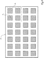
- a network antenna 80 is used, as shown diagrammatically in FIG. figure 4 , comprising a large number of radiating elements 8 i, j , arranged for example according to a matrix distribution and controlled independently via transmission / reception modules (not shown in figure 4 ) similar to those described above.
- Such an architecture allows a fine control of the polarization of the radiated radioelectric signals, by simultaneously using different polarizations on the different radiating elements 8 i, j of antenna or groupings R k of antenna radiating elements. Indeed, the final polarization is the result of the summation of the polarizations obtained by the radiating elements for such an antenna.
- the polarizations are alternated. In this case, cross polarization rates much lower than 20 dB under direct polarization are obtained.
- control module 14 is adapted to control a progressive modification, in time, of the polarization orientation of the transmitted or received radio signal.
- control interface 20 is used, this control interface being operable by an operator.
- the control interface can be integrated in the transmission / reception device 2, or integrated in the functional module 12 of the radar 1, or external.
- the operational operation is little impacted because the radar uses the reflections of the radio signals emitted on obstacles or targets encountered.
- the setting of the transmitting / receiving device for transmitting and receiving radio signals of the same given polarization in a given time interval thus allows a nominal or quasi-nominal operational operation.
- the gradual modification, slow or fast, polarization orientation allows to decoy a detection device 6, which is mismatched in reception for part of the polarization orientations.
- the transmission / reception device 2 implemented in a radar 1, carries out a pulse transmission of radio signal (known as "pulse radar” in English).
- the radio signal emitted is a signal with linear polarization of orientation defined by an inclination angle ⁇ , as explained above with reference to the figure 3 .
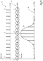
- a pulse transmission is schematically illustrated in the figure 5 in the graph G 1 which represents pulses I k as a function of time.
- each pulse I k is represented, in the graph G 2 , the angle ⁇ k of inclination representation of the polarization orientation of the corresponding radio signal, in the form of a directional vector.
- the graph G 3 schematically illustrates the signal amplitude sensed by the receiver of a detection device as a function of time.
- the amplitude of the signal received / sensed by the detection device gradually decreases on both sides of the climax.
- the progressive modification of the polarization orientation makes it possible, in the illustrated example, to simulate an antenna lobe, of typically Gaussian shape.
- the progressive modification of the polarization orientation has the consequence of simulating an amplitude modulation at the level of the detection device which is therefore decreed with regard to the type of radar. For example, it is possible to simulate a radar in continuous or alternating scanning mode from a radar pointed at a target transmitting polarizing radio signals that evolve over time.
- the orientation change is made from an initial angular orientation, in a progressive manner, either at each pulse or in pulse packets, according to a predetermined bias modification pattern until the return to said initial angular orientation over a predetermined time T 0 .
- the modification is repeated with the same polarization modification pattern during the same duration T 0 .
- a modification makes it possible to simulate a scanning period.
- the polarization modification pattern consists in adding an angular increment of predetermined value ⁇ to each pulse, as illustrated in FIG. figure 5 .
- the value ⁇ is between 10 and 30 degrees.
- the predetermined duration T 0 is chosen according to the type of radar that is to be simulated.
- the polarization modification pattern for example defined by the value of angular increment of value ⁇ and the duration T 0 , is transmitted by the control interface 20, and the polarization modification is implemented by adapting the signaling signals. command sent by the control module 14 to the transmission / reception module (s) 10.
- the polarization modification pattern consists in adding an angular increment of predetermined value ⁇ in packets of pulses, which induces a slower progression.
- the transmitting / receiving device operates in circular polarization
- the progressive modification of the polarization orientation consists of progressively moving from a right circular polarization to a left circular polarization or vice versa.
- the variation is obtained by varying the phase shift by the control signal S ⁇ between excitation signals. of the same amplitude provided on the two pairs of excitation points.
Landscapes
- Engineering & Computer Science (AREA)
- Radar, Positioning & Navigation (AREA)
- Remote Sensing (AREA)
- Computer Networks & Wireless Communication (AREA)
- Physics & Mathematics (AREA)
- General Physics & Mathematics (AREA)
- Variable-Direction Aerials And Aerial Arrays (AREA)
- Radio Transmission System (AREA)
- Radar Systems Or Details Thereof (AREA)
Abstract
Description
- La présente invention concerne un dispositif d'émission/réception de signaux radioélectriques et un procédé d'émission/réception de signaux radioélectriques associés.
- Elle se situe dans le domaine des dispositifs d'émission/réception fonctionnant dans le domaine hyperfréquence et utilisés notamment dans des radars civils ou militaires, au sol ou embarqués.
- De manière connue, de tels radars intègrent des dispositifs d'émission/réception. Chaque dispositif d'émission/réception comporte au moins un module de commande d'émission/réception et au moins un élément rayonnant de signaux radioélectriques, le module de commande étant adapté à commander l'émission/réception de signaux radioélectriques de polarisation linéaire et/ou circulaire.
- Il est également connu d'utiliser des dispositifs de détection de signaux radioélectriques émis par radar qui ont pour objectif d'identifier le radar émetteur. Typiquement, de tels dispositifs de détection interceptent les signaux émis et effectuent des mesures, puis des calculs permettant d'obtenir des paramètres caractéristiques des signaux interceptés, incluant par exemple la fréquence d'émission, la longueur d'impulsion, la fréquence de répétition, la période de rotation d'antenne. Ces paramètres forment une signature électromagnétique d'un radar. A partir de ces paramètres il est possible de déterminer le type de radar en présence, voire d'identifier ce radar en utilisant des bases de données spécialisées.
- Un dispositif de détection comprend typiquement une antenne fonctionnant en réception, adaptée à capter des signaux radioélectriques. En général, pour des raisons de complexité et de coût, les dispositifs de détection sont munis d'antennes à large bande, de manière à maximiser leur capacité de réception. Par exemple, il est fréquent d'utiliser des antennes à large bande de type spirale, adaptées à la polarisation circulaire gauche ou droite, ou bien des antennes large bande de type papillon, adaptées à la réception des polarisations linéaires verticales, horizontales ou inclinées à 45°.
- Dans diverses applications il serait utile de masquer l'identité du radar émetteur, sans toutefois dégrader sensiblement la performance opérationnelle de ce radar.
- L'invention a pour but d'apporter une solution à ce problème, dans le cas des dispositifs d'émission/réception du type adapté à commander l'émission de signaux radioélectriques de polarisation linéaire et/ou circulaire selon une pluralité d'orientations de polarisation, également appelés dispositifs émetteurs/récepteurs à agilité de polarisation en émission et en réception.
- A cet effet, l'invention concerne, selon un premier aspect, un dispositif d'émission/réception de signaux radioélectriques comportant au moins un module de commande d'émission/réception et au moins un élément rayonnant de signaux radioélectriques, le module de commande du dispositif d'émission/réception étant adapté à commander l'émission/réception de signaux radioélectriques de polarisation linéaire et/ou circulaire selon une pluralité d'orientations de polarisation. Ce dispositif est adapté à commander une modification progressive de l'orientation de polarisation des signaux radioélectriques en émission et en réception.
- Avantageusement, le dispositif de l'invention fonctionne de manière à leurrer tout dispositif de détection de radar grâce à la modification progressive de l'orientation de polarisation des signaux radioélectriques émis.
- Avantageusement, le dispositif d'émission/réception selon l'invention peut présenter une ou plusieurs des caractéristiques ci-dessous, prises indépendamment ou en combinaison, selon toutes combinaisons techniquement acceptables.
- La modification progressive de l'orientation de polarisation comprend, à partir d'une orientation de polarisation initiale, une modification progressive d'orientation de polarisation selon un motif de modification d'orientation prédéterminé jusqu'au retour à ladite orientation de polarisation initiale sur une durée temporelle prédéterminée.
- Le module de commande est adapté à répéter itérativement ladite modification progressive d'orientation de polarisation selon ledit motif de modification d'orientation prédéterminé.
- Le module de commande est adapté à commander une émission/réception par impulsions de signal radioélectrique en polarisation linéaire, et la commande de modification progressive de l'orientation consiste à commander une modification d'orientation de polarisation par un incrément angulaire de valeur prédéterminée à chaque impulsion.
- Le module de commande est adapté à commander une émission/réception par impulsions de signal radioélectrique en polarisation linéaire, et la commande de modification progressive de l'orientation consiste à commander une modification d'orientation de polarisation par un incrément angulaire de valeur prédéterminée par paquets d'impulsion.
- Le dispositif comprend au moins un moyen d'émission/réception de signaux radioélectrique comportant un élément rayonnant de signaux radioélectriques et deux paires de points d'excitation, les points d'excitation d'une paire étant disposés symétriquement par rapport à un point central dudit élément rayonnant, et deux modules d'émission/réception adaptés à exciter chacun une desdites paires de points d'excitation.
- Selon un autre aspect, l'invention concerne un procédé d'émission/réception de signaux radioélectriques mis en oeuvre par un dispositif d'émission/réception de signaux radioélectriques comportant au moins un module de commande d'émission/réception et au moins un élément rayonnant de signaux radioélectriques, le module de commande du dispositif d'émission/réception étant adapté à commander l'émission/réception de signaux radioélectriques de polarisation linéaire et/ou circulaire selon une pluralité d'orientations de polarisation. Ce procédé comporte une commande de modification progressive de l'orientation de polarisation des signaux radioélectriques émis/reçus.
- Le procédé d'émission/réception de signaux radioélectriques selon l'invention présente des avantages analogues à ceux du dispositif d'émission/réception de signaux radioélectriques brièvement décrit ci-dessus.
- Avantageusement, le procédé d'émission/réception selon l'invention peut présenter une ou plusieurs des caractéristiques ci-dessous, prises indépendamment ou en combinaison, selon toutes combinaisons techniquement acceptables.
- La commande de modification progressive de l'orientation de polarisation comprend, à partir d'une orientation angulaire initiale, une modification progressive d'orientation angulaire selon un motif de modification prédéterminé jusqu'au retour à ladite orientation angulaire initiale sur une durée temporelle prédéterminée.
- La modification progressive d'orientation angulaire selon un motif de modification prédéterminé est répétée itérativement.
- Le module de commande étant adapté à commander une émission/réception par impulsions de signal radioélectrique en polarisation linéaire, la commande de modification progressive de l'orientation consiste à commander une modification d'orientation de polarisation par un incrément angulaire de valeur prédéterminée à chaque impulsion ou par paquets d'impulsions.
- D'autres caractéristiques et avantages de l'invention ressortiront de la description qui en est donnée ci-dessous, à titre indicatif et nullement limitatif, en référence aux figures annexées, parmi lesquelles :
- la
figure 1 illustre schématiquement un dispositif d'émission/réception de signaux radioélectriques selon l'invention et un dispositif de détection de signaux radioélectriques; - la
figure 2 est un synoptique des principaux blocs d'un dispositif d'émission/réception de signaux radioélectrique à agilité de polarisation ; - la
figure 3 représente un vecteur de polarisation d'un champ électrique rayonné correspondant à une émission de signal radiofréquence ; - la
figure 4 illustre schématiquement une antenne réseau à agilité de polarisation ; - la
figure 5 illustre la polarisation des signaux radioélectriques émis et l'amplitude du signal détecté selon un mode de réalisation de l'invention. - La
figure 1 illustre schématiquement un radar 1 comprenant un dispositif d'émission/réception 2 de signaux radioélectriques 4 qui sont captés par un dispositif de détection 6. - Le dispositif d'émission/réception 2 comporte, dans l'exemple de la
figure 1 , un élément rayonnant 8, ou antenne élémentaire, et un module d'émission/réception 10 (ou T/R module pour « transmission/reception module » en anglais). En émission, le module d'émission/réception 10 amplifie un signal d'excitation radiofréquence, de préférence hyperfréquence entre 3 et 30 GHz, reçu d'un module externe 12 comportant une électronique de génération de signal et adapté à réaliser la fonctionnalité radar, et applique le signal amplifié à l'antenne 8. Ce signal est émis sous forme de signal radioélectrique (ou ondes radioélectriques). En réception, un signal radioélectrique reçu est amplifié par le module d'émission/réception 10 puis transmis au module 12. - Le module d'émission/réception est commandé par un module de commande 14.
- Le dispositif de détection 6 comporte un dispositif de réception 16 et un module 18 de mesure et d'analyse de signaux reçus. Le dispositif de réception 16 comporte notamment une antenne large bande, adaptée pour certaines polarisations de signal radioélectrique reçu dans une bande de fréquence donnée.
- Le module 18 d'un tel dispositif de détection est adapté à mesurer ou calculer des paramètres caractéristiques du signal pour ensuite déterminer le type de dispositif d'émission/réception, par exemple le type de radar 1 utilisant le dispositif d'émission/réception 2.
- Comme indiqué en introduction, un objectif de l'invention est de mettre en défaut une telle identification du type de dispositif d'émission/réception 2 par un dispositif de détection 6.
- Le dispositif d'émission/réception 2 est un dispositif à agilité de polarisation, qui est adapté à émettre et recevoir des signaux radioélectriques de types de polarisation différents parmi les types de polarisation linéaire ou circulaire, et d'orientations de polarisation différentes.
- Le type de polarisation et l'orientation de polarisation sont commandés par le module de commande 14, qui est connecté au module d'émission/réception 10.
- Par exemple, le dispositif d'émission/réception 2 est du type décrit dans la demande de brevet
WO2017/021307 A1 . - Ce type de dispositif d'émission/réception comporte, dans un mode de réalisation schématiquement illustré à la
figure 2 , au moins un élément rayonnant 8 comportant quatre points d'excitation P1, P2, P3 et P4, regroupés en deux paires de points d'excitation : (P1, P3) et (P2, P4). Les deux points d'excitation d'une même paire sont disposés symétriquement par rapport à un point central C de l'élément rayonnant. Le dispositif comporte deux modules d'émission/réception 10a, 10b adaptés à exciter chacun une paire de points d'excitation, par un signal radiofréquence, comme illustré schématiquement dans lafigure 2 , où le module 10a est adapté à exciter la paire (P1, P3) et le module 10b est adapté à exciter la paire (P2, P4). - Le module de commande 14 est adapté à contrôler, en coopération avec le module d'émission/réception 10, l'amplitude, la phase et la polarisation des signaux radioélectriques émis et reçus.
- La
figure 3 illustre un angle d'inclinaison θ dans le cas d'une polarisation linéaire, le vecteurE étant représentatif du champ électrique rayonné par l'élément 8, selon une convention de notation. - Par exemple, avec un dispositif d'émission/réception 2 du type représenté à la
figure 2 , diverses polarisations sont obtenues comme suit : - alimentation par entrée P1 et sortie P3 : polarisation linéaire verticale (θ=0°);
- alimentation par entrée P2 et sortie P4 : polarisation linéaire horizontale (θ=90°);
- alimentation en phase de même amplitude par entrée P1 et sortie P3 et par entrée P2 et sortie P4 : polarisation linéaire d'angle d'inclinaison à 45° droite (θ=+45°);
- alimentation en opposition de phase de même amplitude par entrée P1 et sortie P3 et par entrée P2 et sortie P4 : polarisation linéaire d'angle d'inclinaison à 45° gauche (θ=-45°);
- alimentation déphasée de 90° et de même amplitude par entrée P1 et sortie P3 et par entrée P2 et sortie P4 : polarisation circulaire gauche ;
- alimentation déphasée de -90° et de même amplitude par entrée P1 et sortie P3 et par entrée P2 et sortie P4 : polarisation circulaire droite.
- Le déphasage est commandé par un signal Sθ transmis par le module de commande 14 au module d'émission/réception.
- D'autres possibilités de polarisation, et notamment pour faire varier l'angle d'inclinaison θ dans une polarisation linéaire, sont possibles en modifiant l'amplitude et la phase relative des signaux d'excitation radiofréquence sur les paires de points d'excitation.
- Selon une variante de mise en oeuvre, on utilise une antenne réseau 80 telle que représentée schématiquement à la
figure 4 , comprenant un grand nombre d'éléments rayonnants 8i,j, disposés par exemple selon une répartition matricielle et commandés indépendamment via des modules d'émission/réception (non représentés à lafigure 4 ) analogues à ceux décrits ci-dessus. - Une telle architecture permet un contrôle fin de la polarisation des signaux radioélectriques rayonnés, en utilisant simultanément des polarisations différentes sur les différents éléments rayonnants 8i,j d'antenne ou sur des regroupements Rk d'éléments rayonnants d'antenne. En effet, la polarisation finale est la résultante de la sommation des polarisations obtenues par les éléments rayonnants pour une telle antenne.
- De préférence, afin de limiter les effets de couplage entre éléments rayonnants 8i,j adjacents, les polarisations sont alternées. Dans ce cas, des taux de polarisation croisée largement inférieurs à 20dB sous la polarisation directe sont obtenus.
- Selon l'invention, le module de commande 14 est adapté à commander une modification progressive, dans le temps, de l'orientation de polarisation du signal radioélectrique émis ou reçu.
- Par exemple, une interface de commande 20 est utilisée, cette interface de commande étant opérable par un opérateur. L'interface de commande peut être intégrée au dispositif d'émission/réception 2, ou intégrée au module fonctionnel 12 du radar 1, ou externe.
- Avantageusement, pour un radar utilisant un dispositif d'émission/réception 2 selon l'invention, le fonctionnement opérationnel est peu impacté, car le radar utilise les réflexions des signaux radioélectriques émis sur des obstacles ou cibles rencontrés.
- Le réglage du dispositif d'émission/réception pour émettre et recevoir des signaux radioélectriques de même polarisation donnée dans un intervalle temporel donné permet donc un fonctionnement opérationnel nominal ou quasi-nominal.
- Avantageusement, la modification progressive, lente ou rapide, de l'orientation de polarisation, permet de leurrer un dispositif de détection 6, qui est désadapté en réception pour une partie des orientations de polarisation.
- Dans un premier mode de réalisation de l'invention, le dispositif d'émission/réception 2, mis en oeuvre dans un radar 1, effectue une émission par impulsions de signal radioélectrique (connu sous le nom de « pulse radar » en anglais).
- Le signal radioélectrique émis est un signal à polarisation linéaire d'orientation définie par un angle d'inclinaison θ, comme expliqué ci-dessus en référence à la
figure 3 . - Une émission par impulsions est illustrée schématiquement à la
figure 5 dans le graphe G1 qui représente des impulsions Ik en fonction du temps. - En dessous de chaque impulsion Ik est représenté, dans le graphe G2, l'angle θk d'inclinaison représentation de l'orientation de polarisation du signal radioélectrique correspondant, sous la forme d'un vecteur directionnel. Dans l'exemple illustré l'angle d'inclinaison varie entre θ0=-45° (polarisation de 45° gauche) à θn=135° en passant par θk=45° (polarisation de 45° droite).
- Le graphe G3 illustre schématiquement l'amplitude de signal capté par le récepteur d'un dispositif de détection en fonction du temps. L'enveloppe Adet des amplitudes observées a une forme typiquement Gaussienne qui culmine à la réception du signal radioélectrique de polarisation linéaire d'angle d'inclinaison de θ=45° (polarisation de 45° droite). Il s'agit du point d'adéquation maximale avec le type de récepteur dans cet exemple. L'amplitude de signal reçu/capté par le dispositif de détection diminue progressivement de part et d'autre du point culminant.
- La modification progressive de l'orientation de polarisation permet dans l'exemple illustré de simuler un lobe d'antenne, de forme typiquement Gaussienne.
- Ainsi, la modification progressive de l'orientation de polarisation a pour conséquence la simulation d'une modulation d'amplitude au niveau du dispositif de détection qui est donc leurré en ce qui concerne le type de radar. Par exemple, il est possible de simuler un radar en mode de balayage continu ou alterné à partir d'un radar pointé vers une cible émettant des signaux radioélectriques à polarisation qui évolue dans le temps.
- Selon un mode de réalisation, la modification d'orientation est effectuée à partir d'une orientation angulaire initiale, de manière progressive, soit à chaque impulsion soit par paquets d'impulsions, selon un motif de modification de polarisation prédéterminé jusqu'au retour à ladite orientation angulaire initiale sur une durée temporelle prédéterminée T0.
- Ensuite, la modification est répétée avec le même motif de modification de polarisation durant la même durée T0. Avantageusement, une telle modification permet de simuler une période de balayage.
- Par exemple, le motif de modification de polarisation consiste à ajouter un incrément angulaire de valeur δθ prédéterminée à chaque impulsion, comme illustré à la
figure 5 . De préférence, la valeur δθ est comprise entre 10 et 30 degrés. - De préférence, la dure prédéterminée T0 est choisie en fonction du type de radar qu'on cherche à simuler.
- Le motif de modification de polarisation, par exemple défini par la valeur d'incrément angulaire de valeur δθ et la durée T0, est transmis par l'interface de commande 20, et la modification de polarisation est mise en oeuvre en adaptant les signaux de commande envoyés par le module de commande 14 au(x) module(s) d'émission/réception 10.
- Dans un deuxième mode de réalisation, le motif de modification de polarisation consiste à ajouter un incrément angulaire de valeur δθ prédéterminée par paquets d'impulsions, ce qui induit une progression plus lente.
- Selon un troisième mode de réalisation, le dispositif d'émission/réception fonctionne en polarisation circulaire, et la modification progressive de l'orientation de polarisation consiste à passer progressivement d'une polarisation circulaire droite à une polarisation circulaire gauche ou vice-versa.
- Comme expliqué ci-dessus, lorsque le ou les éléments rayonnants sont excités par des modules d'émission/réception tels que décrits ci-dessus, la variation est obtenue en faisant varier le déphasage par le signal de commande Sθ entre signaux d'excitation de même amplitude fournis sur les deux paires de points d'excitation.
Claims (10)
- Dispositif d'émission/réception de signaux radioélectriques comportant au moins un module de commande d'émission/réception (14) et au moins un élément rayonnant (8) de signaux radioélectriques, le module de commande (14) du dispositif d'émission/réception étant adapté à commander l'émission/réception de signaux radioélectriques de polarisation linéaire et/ou circulaire selon une pluralité d'orientations (θ) de polarisation,
caractérisé en ce que le dispositif est adapté à commander une modification progressive de l'orientation de polarisation des signaux radioélectriques en émission et en réception. - Dispositif selon la revendication 1, dans lequel la modification progressive de l'orientation de polarisation comprend, à partir d'une orientation de polarisation initiale, une modification progressive d'orientation de polarisation selon un motif de modification d'orientation prédéterminé jusqu'au retour à ladite orientation de polarisation initiale sur une durée temporelle prédéterminée.
- Dispositif selon la revendication 2 dans lequel le module de commande (14) est adapté à répéter itérativement ladite modification progressive d'orientation de polarisation selon ledit motif de modification d'orientation prédéterminé.
- Dispositif selon l'une quelconque des revendications 2 à 3, dans lequel le module de commande (14) est adapté à commander une émission/réception par impulsions de signal radioélectrique en polarisation linéaire, et dans lequel la commande de modification progressive de l'orientation consiste à commander une modification d'orientation de polarisation par un incrément angulaire de valeur prédéterminée à chaque impulsion.
- Dispositif selon l'une quelconque des revendications 2 à 3, dans lequel le module de commande (14) est adapté à commander une émission/réception par impulsions de signal radioélectrique en polarisation linéaire, et dans lequel la commande de modification progressive de l'orientation consiste à commander une modification d'orientation de polarisation par un incrément angulaire de valeur prédéterminée par paquets d'impulsion.
- Dispositif selon l'une quelconque des revendications 1 à 5, comprenant au moins un moyen d'émission/réception de signaux radioélectrique comportant un élément rayonnant (8) de signaux radioélectriques et deux paires de points d'excitation (P1, P3 ; P2, P4), les points d'excitation d'une paire étant disposés symétriquement par rapport à un point central (C) dudit élément rayonnant (8), et deux modules d'émission/réception (10a, 10b) adaptés à exciter chacun une desdites paires de points d'excitation.
- Procédé d'émission/réception de signaux radioélectriques mis en oeuvre par un dispositif d'émission/réception (2) de signaux radioélectriques comportant au moins un module de commande d'émission/réception (14) et au moins un élément rayonnant de signaux radioélectriques (8), le module de commande (14) du dispositif d'émission/réception étant adapté à commander l'émission/réception de signaux radioélectriques de polarisation linéaire et/ou circulaire selon une pluralité d'orientations de polarisation (θ), caractérisé en ce qu'il comporte une commande de modification progressive de l'orientation de polarisation des signaux radioélectriques émis/reçus.
- Procédé selon la revendication 7, dans lequel la commande de modification progressive de l'orientation de polarisation comprend, à partir d'une orientation angulaire initiale, une modification progressive d'orientation angulaire selon un motif de modification prédéterminé jusqu'au retour à ladite orientation angulaire initiale sur une durée temporelle prédéterminée.
- Procédé selon la revendication 8, dans lequel ladite modification progressive d'orientation angulaire selon un motif de modification prédéterminé est répétée itérativement.
- Procédé selon l'une des revendications 7 à 9, dans lequel ledit module de commande est adapté à commander une émission/réception par impulsions de signal radioélectrique en polarisation linéaire, et dans lequel la commande de modification progressive de l'orientation consiste à commander une modification d'orientation de polarisation par un incrément angulaire de valeur prédéterminée à chaque impulsion ou par paquets d'impulsions.
Applications Claiming Priority (1)
| Application Number | Priority Date | Filing Date | Title |
|---|---|---|---|
| FR1800117A FR3077695B1 (fr) | 2018-02-06 | 2018-02-06 | Dispositif et procede d'emission/reception de signaux radioelectriques |
Publications (2)
| Publication Number | Publication Date |
|---|---|
| EP3521851A1 true EP3521851A1 (fr) | 2019-08-07 |
| EP3521851B1 EP3521851B1 (fr) | 2021-09-29 |
Family
ID=62749039
Family Applications (1)
| Application Number | Title | Priority Date | Filing Date |
|---|---|---|---|
| EP19155110.0A Active EP3521851B1 (fr) | 2018-02-06 | 2019-02-01 | Dispositif et procédé d'émission/réception de signaux radioélectriques |
Country Status (3)
| Country | Link |
|---|---|
| EP (1) | EP3521851B1 (fr) |
| ES (1) | ES2895656T3 (fr) |
| FR (1) | FR3077695B1 (fr) |
Citations (2)
| Publication number | Priority date | Publication date | Assignee | Title |
|---|---|---|---|---|
| US3540045A (en) * | 1969-01-10 | 1970-11-10 | Nasa | Electromagnetic polarization systems and methods |
| WO2017021307A1 (fr) * | 2015-07-31 | 2017-02-09 | Thales | Dispositif d'emission/reception et antenne associee |
-
2018
- 2018-02-06 FR FR1800117A patent/FR3077695B1/fr not_active Expired - Fee Related
-
2019
- 2019-02-01 ES ES19155110T patent/ES2895656T3/es active Active
- 2019-02-01 EP EP19155110.0A patent/EP3521851B1/fr active Active
Patent Citations (2)
| Publication number | Priority date | Publication date | Assignee | Title |
|---|---|---|---|---|
| US3540045A (en) * | 1969-01-10 | 1970-11-10 | Nasa | Electromagnetic polarization systems and methods |
| WO2017021307A1 (fr) * | 2015-07-31 | 2017-02-09 | Thales | Dispositif d'emission/reception et antenne associee |
Non-Patent Citations (2)
| Title |
|---|
| PAN JIAN ET AL: "Polarization changing technique in macrocosm and it's application to radar", CHINESE JOURNAL OF SYSTEMS ENGINEERING AND ELECTRONICS, SECOND ACADEMY MINISTRY OF AERO-SPACE INDUSTRY, BEIJING, CN, vol. 15, no. 4, 1 December 2004 (2004-12-01), pages 447 - 452, XP011376758, ISSN: 1004-4132, DOI: 10.1109/JSEE.2004.6071509 * |
| WENQUAN CHE ET AL: "Research on single-channel variable polarization system with short switching time", MICROWAVE CONFERENCE, 2000 ASIA-PACIFIC, IEEE, PISCATAWAY, NJ, USA, 3 December 2000 (2000-12-03), pages 1535 - 1538, XP010545198, ISBN: 978-0-7803-6435-6, DOI: 10.1109/APMC.2000.926132 * |
Also Published As
| Publication number | Publication date |
|---|---|
| ES2895656T3 (es) | 2022-02-22 |
| FR3077695B1 (fr) | 2020-12-25 |
| FR3077695A1 (fr) | 2019-08-09 |
| EP3521851B1 (fr) | 2021-09-29 |
Similar Documents
| Publication | Publication Date | Title |
|---|---|---|
| EP3315994B1 (fr) | Radar fmcw multifaisceaux, notamment pour automobile | |
| EP2296007B1 (fr) | Radar à agilité de faisceau, notamment pour la fonction de détection et d'évitement d'obstacles | |
| EP2831615B1 (fr) | Dispositif de détection électromagnétique actif et passif à faible probabilité d'interception | |
| CN104011558B (zh) | 编码的孔径波束分析方法和设备 | |
| EP3577720B1 (fr) | Antenne elementaire a dispositif rayonnant planaire | |
| EP0600799A1 (fr) | Antenne active à synthèse de polarisation variable | |
| EP0322005B1 (fr) | Senseur radioélectrique pour l'établissement d'une carte radioélectrique d'un site | |
| EP2795813A1 (fr) | Procédé et système d'estimation d'une différence de marche d'un signal cible émis par un engin spatial ou aérien | |
| EP3321711B1 (fr) | Dispositif de reception pour antenne a balayage electronique apte a fonctionner en mode radar et resm, et radar equipe d'un tel dispositif | |
| EP4092928B1 (fr) | Antenne réseau planaire | |
| EP3726243B1 (fr) | Procédé de confusion de la signature électronique émise par un radar, et dispositif d'émission/réception adapté pour sa mise en oeuvre | |
| EP3654059A1 (fr) | Procédé de création d'au moins une voie de réception virtuelle par l'utilisation d'une antenne radar et système radar | |
| EP1351333A2 (fr) | Antenne adaptative et radar comportant une telle antenne | |
| EP3521851B1 (fr) | Dispositif et procédé d'émission/réception de signaux radioélectriques | |
| FR2985385A1 (fr) | Procede et systeme d'emission d'une onde electromagnetique radiofrequence | |
| FR3106240A1 (fr) | Système antennaire à rayonnement contrôlé | |
| EP1233282B1 (fr) | Système à émission et réception réparties, notamment radar à émission synthétique et à formation de faisceau par le calcul | |
| US12405339B2 (en) | Systems, methods, and apparatus for processing high frequency signals | |
| BE1032131B1 (fr) | Un système radar de surveillance des déformations à ouverture réelle basé sur PMCW-MIMO | |
| FR3027460A1 (fr) | Systeme antennaire compact pour la goniometrie en diversite de la polarisation | |
| EP1522871B1 (fr) | Radar à formation de voies d'écartométrie synthétiques | |
| EP4560943A1 (fr) | Antenne réseau améliorée pour une calibration en émission et/ou en réception ; ensembles de calibration en émission et/ou en réception | |
| EP4125227A1 (fr) | Antenne reseau | |
| BE476938A (fr) |
Legal Events
| Date | Code | Title | Description |
|---|---|---|---|
| PUAI | Public reference made under article 153(3) epc to a published international application that has entered the european phase |
Free format text: ORIGINAL CODE: 0009012 |
|
| STAA | Information on the status of an ep patent application or granted ep patent |
Free format text: STATUS: THE APPLICATION HAS BEEN PUBLISHED |
|
| AK | Designated contracting states |
Kind code of ref document: A1 Designated state(s): AL AT BE BG CH CY CZ DE DK EE ES FI FR GB GR HR HU IE IS IT LI LT LU LV MC MK MT NL NO PL PT RO RS SE SI SK SM TR |
|
| AX | Request for extension of the european patent |
Extension state: BA ME |
|
| STAA | Information on the status of an ep patent application or granted ep patent |
Free format text: STATUS: REQUEST FOR EXAMINATION WAS MADE |
|
| 17P | Request for examination filed |
Effective date: 20200107 |
|
| RBV | Designated contracting states (corrected) |
Designated state(s): AL AT BE BG CH CY CZ DE DK EE ES FI FR GB GR HR HU IE IS IT LI LT LU LV MC MK MT NL NO PL PT RO RS SE SI SK SM TR |
|
| RIC1 | Information provided on ipc code assigned before grant |
Ipc: G01S 7/03 20060101AFI20210414BHEP Ipc: G01S 7/02 20060101ALI20210414BHEP Ipc: H01Q 21/24 20060101ALI20210414BHEP Ipc: H01Q 9/04 20060101ALI20210414BHEP |
|
| GRAP | Despatch of communication of intention to grant a patent |
Free format text: ORIGINAL CODE: EPIDOSNIGR1 |
|
| STAA | Information on the status of an ep patent application or granted ep patent |
Free format text: STATUS: GRANT OF PATENT IS INTENDED |
|
| INTG | Intention to grant announced |
Effective date: 20210607 |
|
| RAP3 | Party data changed (applicant data changed or rights of an application transferred) |
Owner name: THALES |
|
| RIN1 | Information on inventor provided before grant (corrected) |
Inventor name: CORNIC, PASCAL Inventor name: GARREC, PATRICK Inventor name: POREZ, NICOLAS |
|
| INTG | Intention to grant announced |
Effective date: 20210607 |
|
| GRAS | Grant fee paid |
Free format text: ORIGINAL CODE: EPIDOSNIGR3 |
|
| GRAA | (expected) grant |
Free format text: ORIGINAL CODE: 0009210 |
|
| STAA | Information on the status of an ep patent application or granted ep patent |
Free format text: STATUS: THE PATENT HAS BEEN GRANTED |
|
| AK | Designated contracting states |
Kind code of ref document: B1 Designated state(s): AL AT BE BG CH CY CZ DE DK EE ES FI FR GB GR HR HU IE IS IT LI LT LU LV MC MK MT NL NO PL PT RO RS SE SI SK SM TR |
|
| REG | Reference to a national code |
Ref country code: GB Ref legal event code: FG4D Free format text: NOT ENGLISH |
|
| REG | Reference to a national code |
Ref country code: CH Ref legal event code: EP Ref country code: AT Ref legal event code: REF Ref document number: 1434661 Country of ref document: AT Kind code of ref document: T Effective date: 20211015 |
|
| REG | Reference to a national code |
Ref country code: DE Ref legal event code: R096 Ref document number: 602019007890 Country of ref document: DE |
|
| REG | Reference to a national code |
Ref country code: IE Ref legal event code: FG4D Free format text: LANGUAGE OF EP DOCUMENT: FRENCH |
|
| REG | Reference to a national code |
Ref country code: LT Ref legal event code: MG9D |
|
| PG25 | Lapsed in a contracting state [announced via postgrant information from national office to epo] |
Ref country code: SE Free format text: LAPSE BECAUSE OF FAILURE TO SUBMIT A TRANSLATION OF THE DESCRIPTION OR TO PAY THE FEE WITHIN THE PRESCRIBED TIME-LIMIT Effective date: 20210929 Ref country code: RS Free format text: LAPSE BECAUSE OF FAILURE TO SUBMIT A TRANSLATION OF THE DESCRIPTION OR TO PAY THE FEE WITHIN THE PRESCRIBED TIME-LIMIT Effective date: 20210929 Ref country code: FI Free format text: LAPSE BECAUSE OF FAILURE TO SUBMIT A TRANSLATION OF THE DESCRIPTION OR TO PAY THE FEE WITHIN THE PRESCRIBED TIME-LIMIT Effective date: 20210929 Ref country code: NO Free format text: LAPSE BECAUSE OF FAILURE TO SUBMIT A TRANSLATION OF THE DESCRIPTION OR TO PAY THE FEE WITHIN THE PRESCRIBED TIME-LIMIT Effective date: 20211229 Ref country code: HR Free format text: LAPSE BECAUSE OF FAILURE TO SUBMIT A TRANSLATION OF THE DESCRIPTION OR TO PAY THE FEE WITHIN THE PRESCRIBED TIME-LIMIT Effective date: 20210929 Ref country code: BG Free format text: LAPSE BECAUSE OF FAILURE TO SUBMIT A TRANSLATION OF THE DESCRIPTION OR TO PAY THE FEE WITHIN THE PRESCRIBED TIME-LIMIT Effective date: 20211229 Ref country code: LT Free format text: LAPSE BECAUSE OF FAILURE TO SUBMIT A TRANSLATION OF THE DESCRIPTION OR TO PAY THE FEE WITHIN THE PRESCRIBED TIME-LIMIT Effective date: 20210929 |
|
| REG | Reference to a national code |
Ref country code: NL Ref legal event code: MP Effective date: 20210929 |
|
| REG | Reference to a national code |
Ref country code: AT Ref legal event code: MK05 Ref document number: 1434661 Country of ref document: AT Kind code of ref document: T Effective date: 20210929 |
|
| REG | Reference to a national code |
Ref country code: ES Ref legal event code: FG2A Ref document number: 2895656 Country of ref document: ES Kind code of ref document: T3 Effective date: 20220222 |
|
| PG25 | Lapsed in a contracting state [announced via postgrant information from national office to epo] |
Ref country code: LV Free format text: LAPSE BECAUSE OF FAILURE TO SUBMIT A TRANSLATION OF THE DESCRIPTION OR TO PAY THE FEE WITHIN THE PRESCRIBED TIME-LIMIT Effective date: 20210929 Ref country code: GR Free format text: LAPSE BECAUSE OF FAILURE TO SUBMIT A TRANSLATION OF THE DESCRIPTION OR TO PAY THE FEE WITHIN THE PRESCRIBED TIME-LIMIT Effective date: 20211230 |
|
| PG25 | Lapsed in a contracting state [announced via postgrant information from national office to epo] |
Ref country code: AT Free format text: LAPSE BECAUSE OF FAILURE TO SUBMIT A TRANSLATION OF THE DESCRIPTION OR TO PAY THE FEE WITHIN THE PRESCRIBED TIME-LIMIT Effective date: 20210929 |
|
| PG25 | Lapsed in a contracting state [announced via postgrant information from national office to epo] |
Ref country code: IS Free format text: LAPSE BECAUSE OF FAILURE TO SUBMIT A TRANSLATION OF THE DESCRIPTION OR TO PAY THE FEE WITHIN THE PRESCRIBED TIME-LIMIT Effective date: 20220129 Ref country code: SK Free format text: LAPSE BECAUSE OF FAILURE TO SUBMIT A TRANSLATION OF THE DESCRIPTION OR TO PAY THE FEE WITHIN THE PRESCRIBED TIME-LIMIT Effective date: 20210929 Ref country code: RO Free format text: LAPSE BECAUSE OF FAILURE TO SUBMIT A TRANSLATION OF THE DESCRIPTION OR TO PAY THE FEE WITHIN THE PRESCRIBED TIME-LIMIT Effective date: 20210929 Ref country code: PT Free format text: LAPSE BECAUSE OF FAILURE TO SUBMIT A TRANSLATION OF THE DESCRIPTION OR TO PAY THE FEE WITHIN THE PRESCRIBED TIME-LIMIT Effective date: 20220131 Ref country code: PL Free format text: LAPSE BECAUSE OF FAILURE TO SUBMIT A TRANSLATION OF THE DESCRIPTION OR TO PAY THE FEE WITHIN THE PRESCRIBED TIME-LIMIT Effective date: 20210929 Ref country code: NL Free format text: LAPSE BECAUSE OF FAILURE TO SUBMIT A TRANSLATION OF THE DESCRIPTION OR TO PAY THE FEE WITHIN THE PRESCRIBED TIME-LIMIT Effective date: 20210929 Ref country code: EE Free format text: LAPSE BECAUSE OF FAILURE TO SUBMIT A TRANSLATION OF THE DESCRIPTION OR TO PAY THE FEE WITHIN THE PRESCRIBED TIME-LIMIT Effective date: 20210929 Ref country code: CZ Free format text: LAPSE BECAUSE OF FAILURE TO SUBMIT A TRANSLATION OF THE DESCRIPTION OR TO PAY THE FEE WITHIN THE PRESCRIBED TIME-LIMIT Effective date: 20210929 Ref country code: AL Free format text: LAPSE BECAUSE OF FAILURE TO SUBMIT A TRANSLATION OF THE DESCRIPTION OR TO PAY THE FEE WITHIN THE PRESCRIBED TIME-LIMIT Effective date: 20210929 |
|
| REG | Reference to a national code |
Ref country code: DE Ref legal event code: R097 Ref document number: 602019007890 Country of ref document: DE |
|
| PG25 | Lapsed in a contracting state [announced via postgrant information from national office to epo] |
Ref country code: DK Free format text: LAPSE BECAUSE OF FAILURE TO SUBMIT A TRANSLATION OF THE DESCRIPTION OR TO PAY THE FEE WITHIN THE PRESCRIBED TIME-LIMIT Effective date: 20210929 |
|
| PLBE | No opposition filed within time limit |
Free format text: ORIGINAL CODE: 0009261 |
|
| STAA | Information on the status of an ep patent application or granted ep patent |
Free format text: STATUS: NO OPPOSITION FILED WITHIN TIME LIMIT |
|
| 26N | No opposition filed |
Effective date: 20220630 |
|
| PG25 | Lapsed in a contracting state [announced via postgrant information from national office to epo] |
Ref country code: MC Free format text: LAPSE BECAUSE OF FAILURE TO SUBMIT A TRANSLATION OF THE DESCRIPTION OR TO PAY THE FEE WITHIN THE PRESCRIBED TIME-LIMIT Effective date: 20210929 |
|
| REG | Reference to a national code |
Ref country code: CH Ref legal event code: PL |
|
| REG | Reference to a national code |
Ref country code: BE Ref legal event code: MM Effective date: 20220228 |
|
| PG25 | Lapsed in a contracting state [announced via postgrant information from national office to epo] |
Ref country code: LU Free format text: LAPSE BECAUSE OF NON-PAYMENT OF DUE FEES Effective date: 20220201 |
|
| PG25 | Lapsed in a contracting state [announced via postgrant information from national office to epo] |
Ref country code: SI Free format text: LAPSE BECAUSE OF FAILURE TO SUBMIT A TRANSLATION OF THE DESCRIPTION OR TO PAY THE FEE WITHIN THE PRESCRIBED TIME-LIMIT Effective date: 20210929 |
|
| PG25 | Lapsed in a contracting state [announced via postgrant information from national office to epo] |
Ref country code: LI Free format text: LAPSE BECAUSE OF NON-PAYMENT OF DUE FEES Effective date: 20220228 Ref country code: IE Free format text: LAPSE BECAUSE OF NON-PAYMENT OF DUE FEES Effective date: 20220201 Ref country code: CH Free format text: LAPSE BECAUSE OF NON-PAYMENT OF DUE FEES Effective date: 20220228 |
|
| PG25 | Lapsed in a contracting state [announced via postgrant information from national office to epo] |
Ref country code: BE Free format text: LAPSE BECAUSE OF NON-PAYMENT OF DUE FEES Effective date: 20220228 |
|
| P01 | Opt-out of the competence of the unified patent court (upc) registered |
Effective date: 20230502 |
|
| PG25 | Lapsed in a contracting state [announced via postgrant information from national office to epo] |
Ref country code: SM Free format text: LAPSE BECAUSE OF FAILURE TO SUBMIT A TRANSLATION OF THE DESCRIPTION OR TO PAY THE FEE WITHIN THE PRESCRIBED TIME-LIMIT Effective date: 20210929 Ref country code: MK Free format text: LAPSE BECAUSE OF FAILURE TO SUBMIT A TRANSLATION OF THE DESCRIPTION OR TO PAY THE FEE WITHIN THE PRESCRIBED TIME-LIMIT Effective date: 20210929 Ref country code: CY Free format text: LAPSE BECAUSE OF FAILURE TO SUBMIT A TRANSLATION OF THE DESCRIPTION OR TO PAY THE FEE WITHIN THE PRESCRIBED TIME-LIMIT Effective date: 20210929 |
|
| PG25 | Lapsed in a contracting state [announced via postgrant information from national office to epo] |
Ref country code: HU Free format text: LAPSE BECAUSE OF FAILURE TO SUBMIT A TRANSLATION OF THE DESCRIPTION OR TO PAY THE FEE WITHIN THE PRESCRIBED TIME-LIMIT; INVALID AB INITIO Effective date: 20190201 |
|
| PG25 | Lapsed in a contracting state [announced via postgrant information from national office to epo] |
Ref country code: TR Free format text: LAPSE BECAUSE OF FAILURE TO SUBMIT A TRANSLATION OF THE DESCRIPTION OR TO PAY THE FEE WITHIN THE PRESCRIBED TIME-LIMIT Effective date: 20210929 |
|
| PG25 | Lapsed in a contracting state [announced via postgrant information from national office to epo] |
Ref country code: MT Free format text: LAPSE BECAUSE OF FAILURE TO SUBMIT A TRANSLATION OF THE DESCRIPTION OR TO PAY THE FEE WITHIN THE PRESCRIBED TIME-LIMIT Effective date: 20210929 |
|
| PGFP | Annual fee paid to national office [announced via postgrant information from national office to epo] |
Ref country code: GB Payment date: 20260219 Year of fee payment: 8 |
|
| PGFP | Annual fee paid to national office [announced via postgrant information from national office to epo] |
Ref country code: ES Payment date: 20260309 Year of fee payment: 8 |
|
| PGFP | Annual fee paid to national office [announced via postgrant information from national office to epo] |
Ref country code: DE Payment date: 20260206 Year of fee payment: 8 |
|
| PGFP | Annual fee paid to national office [announced via postgrant information from national office to epo] |
Ref country code: IT Payment date: 20260209 Year of fee payment: 8 |
|
| PGFP | Annual fee paid to national office [announced via postgrant information from national office to epo] |
Ref country code: FR Payment date: 20260227 Year of fee payment: 8 |